Embed Size (px)
Citation preview

TECHNOLOGICAL PARAMETERS OF EXPLOSION-
BONDED. TITANIUM CLADDING ON STEEL
Dr. -Ing. Klaus Rtidinger Managing Director, Technical
Contimet GmbH Krefeld, Germany
In tackling their corrosion-chemical problems the chemical industries generally use commercially pure titanium. Apparatus made from ·solid titanium and titanium-lined vessels have stood the test equally well. At elevated temperatures, the tensile values fall 'off.· For this reason, and because of certain economic considerations especially for pressure vessels, the maximum temperatures applied are as a rule not above 250°C, while wall thicknesses generally do not exceed approximately 10 mm. For titanium-lined vessels temperatures do not surpass 200°C, the basic factors underlying the temperature limit being the dimensions of the vessel, the mode of fastening the lining to the outer shell, and the given operating conditions. The technique of explosion-bonding titanium claddings on steel has opened up new possibilities for applying titanium on a larger scale at higher temperatures even than earlier mentioned. It also enables better thermal transition values to be attained than they are obtainable in titanium-lined apparatus.
Literature furnishes exact details on the technique of combining two materials through explosion-bonding and explains fully the procedures of preparation and execution of the work involved (1-9). Details have also been· published on the technological properties of explosion-bonded claddings of the combination type titanium-steel (10-12).
2313
2314 K. RUDINGER
The work described in this report is concerned with the influence of shock waves and of heat treatments on the structure and on the behavior of cladding and backing material.
Test Procedure
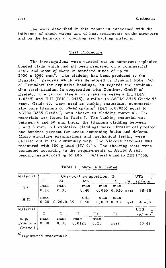
The investigations were carried out on numerous explosivebonded clads which had all been prepared on a commercial scale and most ~f them in standard sizes of up to 2000 x 6000 mm . The cladding had been produced to the Dynaplatx) process which was developed by Dynamit Nobel AG of Troisdorf for explosive bondings, as regards the combination steel-titanium in cooperation with Contimet GmbH of Krefeld. The carbon steels for pressure vessels HI (DIN 1. 0345) and H II (DIN 1. 0425), similar to AST M A515 Grade 55 resp. Grade 60, were used as backing materials, commercially pure titanium of 30-42 kp/mm2 (DIN 3. 07025) equal to ASTM B265 Grade I, was chosen as cladding material. The materials are listed in Table I. The backing material was between 6 and 50 mm thick, the titanium cladding between 2 and 6 mm. All explosive claddings were ultrasonically tested one hundred percent for areas containing faults and defects. Micro structure examinations and mechanical testing were carried out in the customary way. The Vickers hardness was measured with 100 g load (HV O. 1 ). The shearing tests were conducted according to the requirements of ASTM A 265, bending tests according to DIN 1604/sheet 4 and to DIN 17155.
Table I. Materials Tested
Material Chemical composition, "lo UTS c Si Mn p s Fe kp/mm
2
HI max max max max max o. 16 o. 35 0.40 o. 050 o. 050 rest 35-45
HII max min max max 0. 20 o. 20-0. 35 o. 50 0.050 o. 050 rest 41-50
Material UTS 2 c N H Fe Ti kp/mm
c. p. max max max max Titanium 0. 08 o. 05 0.0125 0.20 rest 30-42 Grade I
x)registered trademark
TECHNOLOGICAL PARAMETERS OF EXPLOSION-BONDED CLADDING ON STEEL 2315
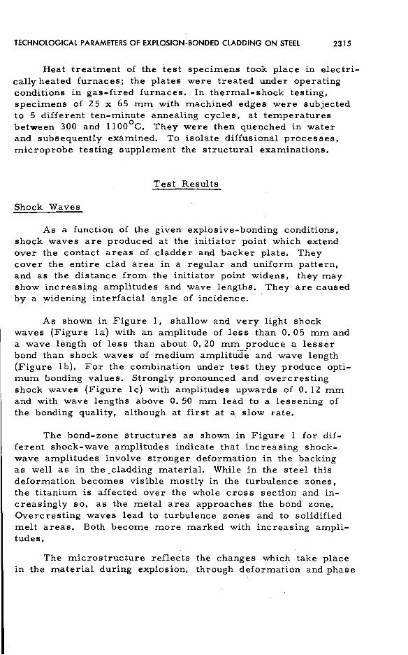
Heat treatment of the test specimens took place in electrically heated furnaces; the plates were treated under operating conditions in gas-fired furnaces. In thermal-shock testing, specimens of 25 x 65 mm .with machined edges were subjected to 5 different ten-minute annealing cycles, at temperatures between 300 and l l00°C. They were then quenched in water and subsequently examined. To isolate diffusional processes, microprobe testing supplement the structural examinations.
Test Results
Shock Waves
As a function of the given explosive-bonding conditions, shock waves are produced at the initiator point which extend over the contact areas of cladder and backer plate. They cover the entire clad area in a regular and uniform pattern, and as the distance from the initiator point widens, they may show increasing amplitudes and wave lengths. They are caused by a widening interfacial angle of incidence.
As shown in Figure 1, shallow and very light shock waves {Figure la) with an amplitude of less than 0. 05 mm and a wave length of less than about O. 20 mm produce Cl- lesser bond than shock waves of medium amplitude and wave length {Figure 1 b). For the combination under test they produce optimum bonding values. Strongly pronounced and overcresting shock waves {Figure le) with amplitudes upwards of O. 12 mm and with wave lengths above O. 50 mm lead to a lessening of the bonding quality, although at first at a, slow rate.
The bond-zone structures as shown in Figure 1 for different shock-wave amplitudes indicate that increasing shockwave amplitudes involve stronger deformation in the backing as well as in the_ cladding material. While in the steel this deformation becomes visible mostly in the turbulence zones, the titanium is affected over the whole cross section and increasingly so, as the metal area approaches the bond zone. Overcresting waves lead to turbulence zones and to solidified melt areas. Both become more marked with increasing amplitudes.
The microstructure reflects the changes which take place in the material during explosion; through deformation and phase

2316
Fig. 1.
~-?tzti~~~~:~.z;;_::~~~t~~0%I~~t1~~~ ' '"" ' - ;>: .... -,! ... ·-' .,M""'.9V""• ·~ . ' !it"'..:..~--~~-- ... ~. ,. ,t',. -- -,: '. ··-~. >·-·r> _,. .. .,; .r~_:tt · ·.,·.,! ... ).";:';. ·.-~r-~,~=:-_.4- : __ -~~ J_-1.~ t"'~-'t. .... l'/~:"!.f-,·.·.r ... ,(·""·~-'""· ,.,~ .-'• c .• :·~···6r!';~·
,..
. .. ,
A
' ·~)-\;'~-::Y.;;.I .,. )-.r~· . - ,_....~ ~"'• >- . -~~,_-.·,~,~ .... ;;~ ....... ::; >.. ...... ~.-;&,,.~~ J:~·-=-- .. ·~j-.,_.-t(~-···.J..~ •}-;;,. ~~-:r .• ~ .. '~
~:;~,,~~?{{~;~,~~~.:~2:s ~;;.~~·~ ~ :~:~-.? B
c
K. RUDINGER
Bond zones with shock waves of different amplitudes in the as clad condition. x 100. (a) Waves of low amplitude with low bond, (CP 475); (b) intermediate wave amplitude with excellent bond, (CP 477); (c) strongly pronounced waves with solidification zones, but still good bond, (CP 469).
TECHNOLOGICAL PARAMETERS OF EXPLOSION-BONDED CLADDING ON STEEL 2317
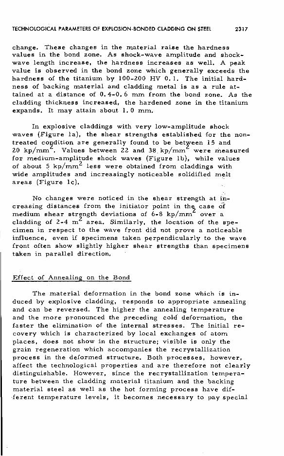
change. These changes in the material raise the hardness values in the bond zone. As shock-wave amplitude and shockwave length increase, the hardness increases as well. A peak value is observed in the bond zone which generally exceeds the hardness of the titanium by 100-200 HV 0. 1. The initial hardness of backing material and cladding metal is as a rule attained at a distance of O. 4-0. 6 mm from the bond zone. As the cladding thickness increased, the hardened zone in the titanium expands. It may attain about 1. 0 mm.
In explosive claddings with very low-amplitude shock waves (Figure la), the shear strengths established for the nontreated condition are generally found to be between 15 and 20 kp/mm
2. Values between 22 and 38_ kp/mm2 were measured
for medium-amplitude shock waves (Figure 1 b), while values of about 5 kp/mm2 less were obtained from claddings with wide amplitudes and increasingly noticeable solidified melt areas (Figure le). .
No changes were noticed in the shear strength at increasing distances from the initiator point in th~ case o'f· medium shear strength deviations of 6-8 kp/mm over a cladding of 2-4 m 2 area. Similarly, the location of the specimen in respect to the wave front did not prove a noticeable influence, even if specimens taken perpendicularly to the wave front often show slightly higher shear strengths than specimens taken in parallel direction.
Effect of Annealing on the Bond
The material deformation in the bond zone which is induced by explosive cladding, responds to appropriate annealing and can be reversed. The higher the annealing temperature and the more pronounced the preceding cold deformation, the faster the elimination of the internal stresses. The initial recovery which is characterized by local exchanges of atom places, does not show in the structure; visible is only the grain regeneration which accompanies the recrystallization process in the deformed structure. Both processes, however, affect the technological properties and are therefore not clearly distinguishable. However, since the recrystallization temperature between the cladding material titanium and the backing material steel as well as the hot forming process have dif·ferent temperature levels, it becomes necessary to pay special
2318 K. RUDINGER
attention to the influence of annealing treatments on the adhesive strength of the bond in the temperature range which is to be applied to the two materials.
Microstructure
Figure 1 shows that in the as clad condition the cold deformation in the area of the bond zone, caused by explosion cladding, can be clearly distinguished in the two materials in the microstructure.
Annealing at temperatures to below 500°C does not result in changes of the microstructure. From that temperature onwards, titanium begins to recrystallize (Figure Za). After not more than 4 h annealing at 580°C, extensive recrystallization is noticeable (Figure Zb). The process is completed after 90 min. annealing at 700°C (Figure Zc). Longer annealing times lead to grain growth, while one hour annealing only at 800°c causes grain coarsening. Tests have shown that from 900°C onwards a passing of the (? -transus involves pronounced grain growth and leads to a p-decomposition structure during cool~ng. These results coincide with the data obtained from a former study on the recrystallization behavior of commercially pure titanium ( 13 ).
As far as the steel is concerned, recrystallization was 0
found to commence at 800 C, as expected. The process was completed after one hour annealing at 900°C.
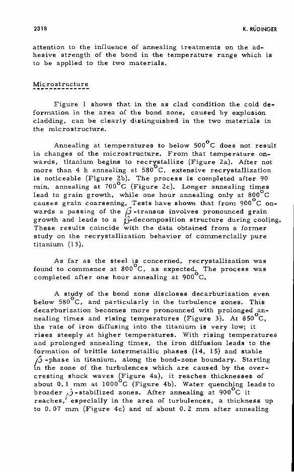
A study of the bond zone discloses decarburization even below 580°C, and particularly in the turbulence zones. This decarburization becomes more pronounced with prolonged annealing times and rising temperatures (Figure 3). At 8S0°C, the rate of iron diffusing into the titanium is very low; it rises steeply at higher temperatures. With rising temperatures and prolonged annealing times, the iron diffusion leads to the formation of brittle intermetallic phases (14, 15) and stable. ;3 -phase in titanium, along the bond-zone boundary. Starting {n the zone of the turbulences which are caused by the overcresting shock waves bFigure 4a), it reaches thicknesses of about O. 1 mm at 1000 C (Figure 4b). Water quenching leads to broader ,,)-stabilized zones. After annealing at 900°C it reaches.' especially in the area of turbulences, a thickness up to O. 07 mm (Figure 4c) and of about O. 2 mm after annealing

TECHNOLOGICAL PARAMETERS OF EXPLOSION-BONDED CLADDING ON STEEL 2319
Fig. 2. Recrystallization of titanium in the bond zone after annealing. x 100. (a) Beginning recrystallization after annealing lh at 5800C/AC, (CP 938); (b) partly recrystallized after annealing 4h at 580°C/AC, (CP 940); (c) fully recrystallized after annealing 90 min at 700°C/AC, (CP 943).

2320 K. RUDINGER
[; /"
Fig. 3. Decarburization on the steel side of the bond zone, annealed 50 min at 700°C/WQ, (CP 704).
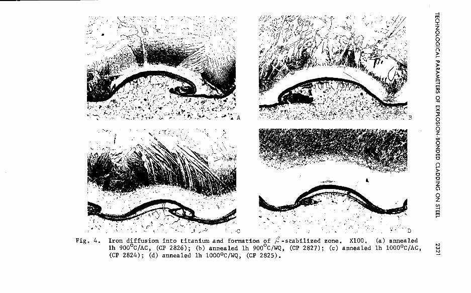
Fig. 4.
./
'. i
. ~ · ..... ;
. \ $~
' . ·C
J'
./-.
Iron diffusion into titanium and formation of ;'.?-stabilized zone. XlOO, lh 900°C/AC, (CP 2826); (b) annealed lh 900°C/WQ, (CP 2827); (c) annealed (CP 2824); (d) annealed lh l000°C/WQ, (CP 2825).
;,J 2 • j~ •• •
I~. D
(a) annealed lh iooo0 c/Ac,
-t m ("'\ :I: z 0 5 G)
n )>
.,, )>
"' )>
~ m -t m
"' V>
0 .,, m x .,, 5 V>
6 z "" 0 z 0 m 0 ("'\ .--)> 0 0 z G)
0 z V> -t m ::?!

2322 K. RUDINGER
at 1000°C. In the water quenched condition the limiting content of the ;3-stabilized zone must surpass 4 3 iron, according to the critical alloying content of titanium-iron alloys (16). This is confirmed by additional microprobe tests, which show that the iron content increases up to 65 3 in the bond zone. Above 1050°C, the formation of titanium-iron eutectic leads to fusion (17). At the same time as iron diffuses into the cladding metal, titanium is found to diffuse into the backing material, although at a much lower rate and impeded by the formation of titanium carbides. The diffusion zone of titanium reaches after annealing at I000°C, lh, values of 0. 04 mm.
Hardness
The maximum hardness in the bond zone of explosionbonded material is shifted by rising temperatures and by the accompanying material recovery and recrystallization, to lower values. This is shown in Figure 5 for 550°C and 700°c which are the temperature levels for the stress-relieving and recrystallizing annealing of titanium and which cover also the stress-relieving annealing range of the backing steels.
At higher annealing temperatures and prolonged annealing times, the reduction of cold deformation in the explosionbonded cladding is superimposed by the diffusion process above described (Figure 6). While in the backer mat~rial steel recrystallization goes on at annealing temperatures up to 950°C and is eventually completed, the decarburization taking place above of 600°C close to the bond zone, leads to an additional loss of hardness.
In the cladding material titanium, hardness values are found to rise above 800°C. This rise in hardness sets in at the bond zone. It is due to the diffusion of iron and the simultaneous diffusion of titanium. Another cause is the formation of carbides and of intermetallic cf'_hases. Peak values of over 500 HV O. 1 are reached at 950 C. Additionally, from 900°C onwards, when the ;5 -transus is passed, the inherent hardness in the titanium rises to about 200 HV O. 1.
Contrary to cooling in air, a quenching of the claddings produces the same peak values both at the bond zone and in the titanium. In the steel, on the other hand, quenching above 800°C causes the hardness of the backer material to rise to

TECHNOLOGICAL PARAMETERS OF EXPLOSION-BONDED CLADDING ON STEEL 2323
340
Thickness of claddings IHI• 15 + 2 mm
• o 15 + 6 mm 300' ,y • 6 + 2 mm
~ - 260 ~~*- .. 0 ~~ 0
A
> 2t I . Ill 0 Ill 220
~ Q) c: 'O 6 iii .'t' .r. .. Ill .._
180 Q) .::t. 0 6
> I
~
140 t
100 2 hrs 550°c; AC 2 hrs 100°c; AC as clad
Fig. 5. Hardness of bond zone at different annealing conditions.

2324 K. RUDINGER
500
** 0 as clad e 550°C 1h t:. 650°C 1h
450 A 700°c 1h 0 800°c 1h
• 900°c 1h
* 950°c 1h
400
350
0 ' . • I
> !* I
Ill 300 Ill Cll c "O :o
.s::. Ill Q; .:.: u 250
>
100L-~~---'L.,_~~---L~~~--L~~~....l-.~~~_._~~--I
1. 5 1,0 0,5 0 0,5 1,0 1. 5 Steel backer plate Titanium cladder plate
Di stance from bond zone, mm
Fig. 6. Effect of annealing temperature on hardness at different distances from bond zone.
TECHNOLOGICAL PARAMETERS OF EXPLOSION-BONDED CLADDING ON STEEL 2325
values around 370 HV O. 1. In the carbon-impoverished zone, these values are not obtained. They fall off with the carboncontent to reach peak values, in the bond zone, of about 230
HV 0. 1 only.
The shear strength as a parameter for the resistance of the cladding bond zone to stresses exerted on the cladding plane, is at its highest in the non-treated condition. Rising annealing temperatures of up to 550°C do not noticeably reduce it. The mean values at 550°C are about 10 % lower than in the unannealed condition (Figure 7). This reduction is chiefly due to the relaxation of cold deformation. Both the location of the specimen in respect to the wave front and the annealing time do not appreciably affect the shear strength. Annealing temperatures above 550°C lead to a reduction of the shear strength so that above 700°C values of 14 kp/mm2 are not reached. Very low shear strengths must be expected above of 900 to 9so 0 c.
Specimens were annealed at given temperatures and then quenched in water, in order to determine the effect of quenching stresses on the shear strength. Up to 800°C, 5 quenching sequences did not affect the shear strength. As Figure 8 shows, higher quenching temperatures result in an abrupt drop to a low position with values of around 14 kp/mm2 . It is to be expected that prolonged annealing times and more effective throughheating will shift this low level to even lower values. Nevertheless, ultrasonic testing confirmed that the titanium cladding had nowhere come off.
Bendability tests carried out in addition to shear strength testing showed that up to 800°C the bending radii comply with requirements for both backer material and plate thickness without any instances of the cladding coming off. In this connection it is immaterial, whether the titanium cladding is applied to the side which has to take the tensile stresses or to that taking the compressive stresses, or whether the specimens concerned are lateral bending test specimens. This is shown in Figure 9.
Up to the normalizing temperature of 890°C, tensile tests carried out both on the cladding, and on the backing material,

2326 K. RUDINGER
60 -......---.--1----.---1.---1--1--• parallel to wave front
50 -----+-----+---- o perpendicular to wave front
annealing time: 1 - 2 hours
N
E E
I 40 ~j.~-t----+-----+-•~--f-----+------1-----1 ·~ . . l ' ,..,,,_ . . \t 0
0 I J 1 :5, 30 ~:f. __ ~~~;~-1--~r~-_...,¢L~~ II c: ';:' • • • -!". :. : ~ 0
• l-ir.- : i :=
~
~ ·~ .... . . ~
~ 2Q >-----+-----+-------+-~L:-=-·~·------o"----+-----4 00 ·¥ ~
·~ • •g e•• • • 14 .,__ _____ ------~---900-!!,_o_:-!:--------
• . . ·:-10 1-----+------t-----t----r-------t-. . . . .
I 500 700 900
O'--_.__I_._ ____ _._ ____ __._ ____ _._ ____ _._ ____ _._ ____ -' as 100 300 1100
clad Annealing temperature ,
0 c Fig. 7. Effect of annealing temperature on shear-strength of
explosion bonded titanium-steel claddings.
40
N E 30 E ' a. x. -~
Ci 20 c: ~ iii Co Q) 10 ~
00
0
I 0
( () (~ 0 0 < 0 -0 0 (
0 0 0
Treatment: 5 times 10 minutes at temperature
fol lowed by water quenching l
\.! ) ......._ ()
I 100 300 500 700 900 as
clad Water quenching temperature,
0c
0
v 1
1100
Fig. 8. Effect of water quenching on shear-strength of explosion bonded titanium-steel claddings.

TECHNOLOGICAL PARAMETERS OF EXPLOSION-BONDED CLADDING ON STEEL 2327
Fig. 9. Bend test samples of explosion bonded titanium-steel claddings, stress relieved at 2h 550°c with clad in tension, compression plus tension, compression, (CP 1707).

2328 K. RUDINGER
both in the as received condition and after the annealing treatments, showed values for yield strength, elongation and DVM impact strength, which exceed the permissible minimum values, and tensile values which are well within the specified strength range. This is listed in Table II.
Table II. Mechanical properties of explosion clad titanium-steel composite 1 5 + 2 mm.
Material UTS YS 2
EL DVM- Treatment kp/mm2 kp/mm 200 mm Impact
2 kpm/cm
H IIx) 41-50 26 20 7 normalized c. p. Ti grade I
30-42 20 25 9 annealed
H II + Ti-clad xx) 49 40 22 18-25 as clad
II 49 39 27 12-16 lh 550°C/AC II 46 35 27 15-25 lh 625-700°C/AC II 48 35 30 11-21 l/2h 890°C/ AC
x)with 0.13%CO. 21%Si0. 56%Mn0. Ol8%P0.021"/oS
xx) mean of 30 samples.
Summary and Conclusion
The influence of shock waves and of annealing treatments on explosive claddings was determined on specimens of claddings of primarily commercial sizes with the carbon steels for pressure vessels H I and H II being used as backing material and commercially pure titanium of 30-42 kp/mm2 tensile strength as cladding material. Both, backing and cladding materials were used in different thicknesses. It was found that increasing shock wave amplitudes and increasing shock wave lengths promote material deformation, particularly in the bond zone, and that they extend the deformed area. Very pronounced shock waves with a good deal of solidified melt areas in the turbulence zones. of the overcresting waves reduce the bonding. Annealing reverses material deformation and reduces the hardness peak in the bond zone.

TECHNOLOGICAL PARAMETERS OF EXPLOSION-BONDED CLADDING ON STEEL 2329
Structurally, rising annealing temperatures and prolonged annealing times are found to cause recrystallization of backing and cladding material. In addition, the bond zone shows diffusion phenomena which start in the turbulence zones. Decarburization begins in the steel even below 580°C, and particularly marked is the diffusion of iron into the titanium which -starts at 850°C and leads to /3-stabilized areas. The diffusion of titanium is a much slower process. Fusion is first observed at 1050°C. The titanium bond zone with its iron content of up to 65 % has high hardnesses of up to 500 HV O. 1.
In the as clad condition the shear strength generally attains values of over 25 kp/mm2 . Up to 5509 C, rising annealing temperatures reduce it by 10 % only. Annealing above 700°C, on the other hand, reduces the shear strength to values below the specified minimum of 14 kp/mm2. For the backing material, bendability and tensile strength as well as impact values correspond with the respective specification values.
The investigation has shown that explosion-bonded claddings of the material combination concerned can be used in operation at temperatures up to at least 500°C. This means that titanium can be applied in the construction of chemical apparatus on a much larger scale than before. In hot forming operations, though, such as the pressing of vessel bottoms, the heating temperature should not exceed 700 °c, so that pressing can take place between 650°C and 550°C. The most appropriate temperature range for annealing treatments is 550°C - 625°C. as this produces the most suitable conditions in both backing and cladding material and ensures reliable bonding qualities.
References
1. Cowan, G. R. and Holtzman, A.H. , "Flow-Configuration in Colliding Plates-Explosive Bonding," J. appl. Physics, Vol. 34, No. 4, 1963, pp. 928-939.
2. Holtzman, A.H. and Cowan, G. R. , "Bonding of Metals with Explosives," Welding Research Council Bulletin, No. l 04, April 1965, American Welding Soc. , New York, N. Y.
2330 K. RUDINGER
3. Bergmann, 0. R. , Cowan, G. R. and Holtzman, A.H. , "Experimental Evidence of Jet Formation During Explosion Cladding, " Trans. Met. Soc. AIME, Vol. 236, May 1966, pp. 646-653.
4. Klein, W. , "Verbundmechanismus beim Explosionsschwei!3en," Schwei!3en und Schneiden, Vol. 19, No. 4, 1967, pp. 1-4.
5. Bohm, G. , "Plattieren von Stahl mit Sondermetallen, insbesondere Molybdan, nach dem Schockwellenverfahren," Z. Metallkunde, Vol. 59, No. 2, 1968, pp. 104-111.
6. Keller, K. , "Beitrage zum Explosionsplattieren," Z. Metallkunde, Vol. 59, No. 4, 1968, pp. 298-305 and No. 5, pp. 806-811.
7. Ruppin, D. , "Schwei!3en von Metallen mit Explosionswerkstoffen, " Techn. Uberwachung, Vol. 9, No. 4, 1968, pp. 105-108.
8. Schwarz, L., "Explosionsformgebung, -plattieren und -harten," Berg- und Htittenmannische Monatshefte, Vol. 113, No. 11, 1968, pp. 405-415.
9. Richter, U. and Roth, J., "Grundlagen und Anwendung des Sprengplattierens, " Naturwis senschaften, Vol. 57, No. 10, 1970, pp. 487-493.
10. DeMaris, J. L. and Pocalyko, A., "Mechanical Properties of Detaclad Explosion-Bonded Clad Metal Composites," Technical Paper, Preprint AD66-l l 3, Am. Soc. Tool & Manufacturing Eng. , Deaborn, Mich. , 1966.
11. Klein, W. , "Festigkeitsprtifung von explosionsgeschwei!3ten Verbundwerkstoffen," Materialprtifung, Vol. 10, No. 3, 1968, pp. 73-77.
12. Rtidinger, K. , "Technologische Eigenschaften von Titansprengplattierungen," Z. Werkstofftechnik/J. of Materials Technology, Vol. 2, No. 4, 1971, pp. 169-174.
13. Bungardt, K. and Rtidinger, K. , "Rekristallisationsverhalten von Titan," Metall, Vol. 14, No. 10, 1960, pp. 988-994.

TECHNOLOGICAL PARAMETERS OF EXPLOSION-BONDED CLADDING ON STEEL 2331
14. Weiss, B. - Z., "Fatigue Crack Propagation in an Explosively Bonded Titanium Steel System, " Z. Metallkunde, Vol. 62, No. 6, 1971, pp. 489-493.
15. Klein, W. and May, W. , "Diffusionsvorgange in der Kontaktzone von Titan/Stahl-Sprengplattierungen, " z. Werkstofftechnik/J. of Materials Technology, Vol. 3, No. 1, 1972, pp. 13-17.
16. Jaffee, R. I. , "General Physical Metallurgy of Titanium Reviewed," J. Metals, Vol. 7, No. 2, 1955, pp. 247-252.
17. Hansen, M., Constitution of Binary Alloys, Metallurgy and Metallurgical Engineering Series, 2nd Edition, New York/London/Toronto, 1958, McGraw-Hill, Book Company.