Embed Size (px)
Citation preview
Technology for a better society
I2nd International Forum on recent Developments of CCS Implementation
16th-17th December 2015, Athens Greece
1
Geir Skaugen, SINTEF ER
Simon Roussanaly, SINTEF ER
Techno-Economic Evaluation on the Effects of Impurities for Conditioning and Transport of CO2 by Pipeline

Technology for a better society
• The effect of impurities on the thermodynamic properties of CO2 relevant for case studies
• Description case study –compressed gas for pipeline transport
• Effect of impurities on;
• Pipeline design
• Energy consumption
• Cost
• Conclusion
2
Introduction – Content of presentation
Technology for a better society 3
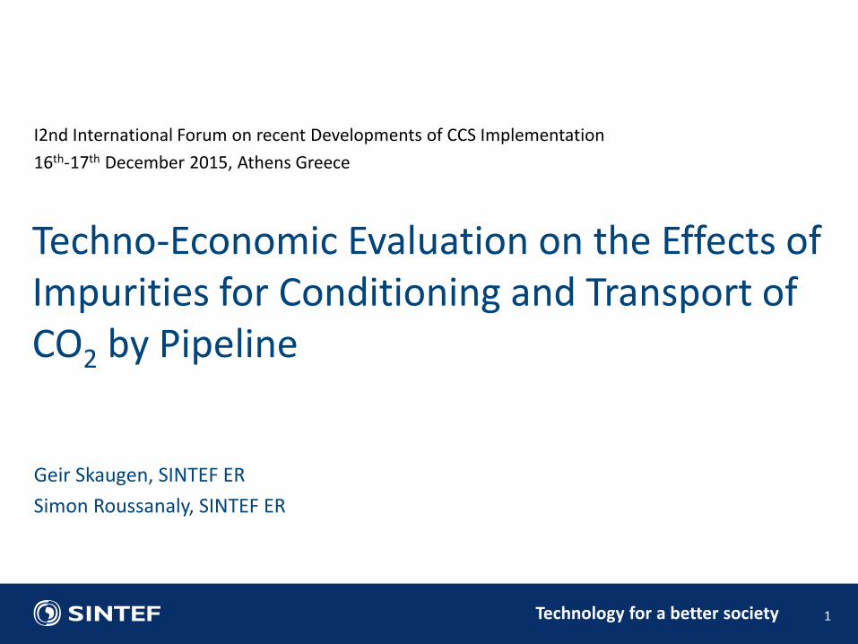
Effects of impurities on CO2 thermodynamic
Temperaturepressurecomposition
VAPOUR
LIQUID
FEEDLIQUID
VAPOUR

Technology for a better society 4
Effects of impurities on density (predictions)
≈50%

Technology for a better society 5
Effects of impurities on viscosity (predictions)
≈50%

Technology for a better society 6
Pipeline transport of CO2
Pipeline transport and reboosting
Reboosting Reboosting
15015090
P
Legend:
Pressure (bar)
Temperature (°C)T
25
200
25
Conditioning for transport
Captured CO2
from an emitter

Technology for a better society 7
Pipeline transport of CO2
Pipeline transport and reboosting
Reboosting Reboosting
15015090
P
Legend:
Pressure (bar)
Temperature (°C)T
25
200
25
Conditioning for transport
Captured CO2
from an emitter

Technology for a better society
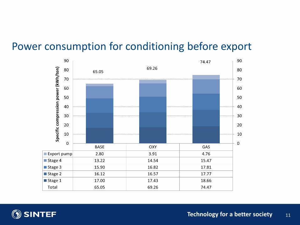
CASE CO2 H2O N2 O2 Methane
«BASE» 93 7
«OXY» 88 7 3 2
«GAS» 83 7 1 9
8
Cases, impurity levels and boundary conditions
Initial condition: Atmospheric (1.027 bar and 25°C) Export condition: 150 bar (35-38 °C) Ambient temperature 15°C with low heat transfer: - Ground thermal conductivity: 2.4 W/m K - Ambient heat transfer: 5.0 W/m²K Total transport distance: 500 km Pipeline: On-shore @ depth 1.0 m, varying diameter Feed flow rate: 500 kg/s (13.1 MTPA)
Maximum impurity levels
Technology for a better society 9
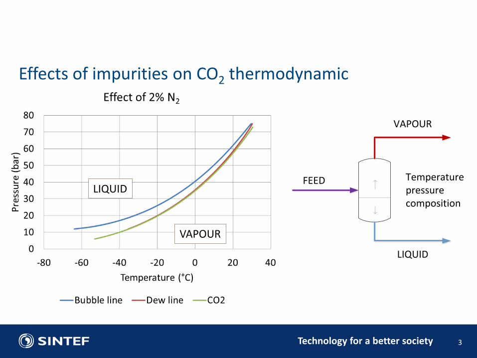
Pipeline transport – conditioning
Feed after capture
1501
P
Legend:
Pressure (bar)
25
25 25 25 25
Temperature (°C)T
3.3 9.5 28 85
Vapour
LiquidCompression
Cooling
Separation
To pipeline

Technology for a better society 10
Pipeline transport – conditioning
Transport at 150 bar and ~36°C
1501
P
Legend:
Pressure (bar)
25
25 25 25 25
Temperature (°C)T
3.3 9.5 28 85
Vapour
LiquidCompression
Cooling
Separation
Two-phase region
Pure CO2
Feed – humid gas at atmospheric pressure
Technology for a better society 11
Power consumption for conditioning before export

Technology for a better society 12
Power comsumption for conditioning for export
+15%
Technology for a better society
Question: "Will a crack in the pipeline, when initiated, propagate or will it stop?
Known as "Running Ductile Fractures" – or RDF and "crack arrest"
13
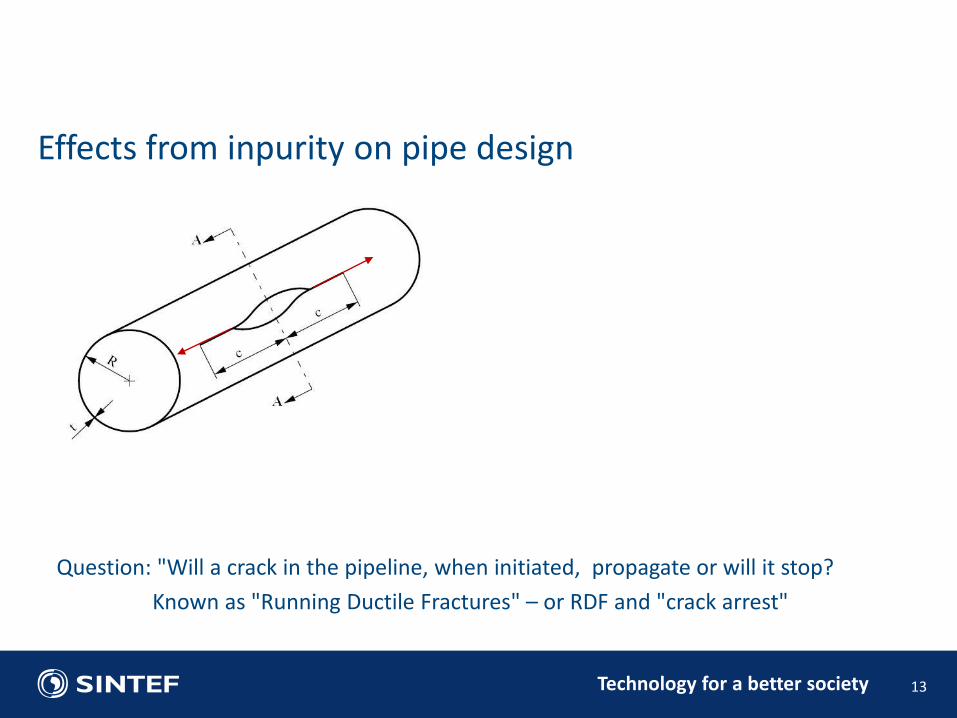
Effects from inpurity on pipe design

Technology for a better society
Question: "Will a crack in the pipeline, when initiated, propagate or will it stop?
Known as "Running Ductile Fractures" – or RDF and "crack arrest"
14
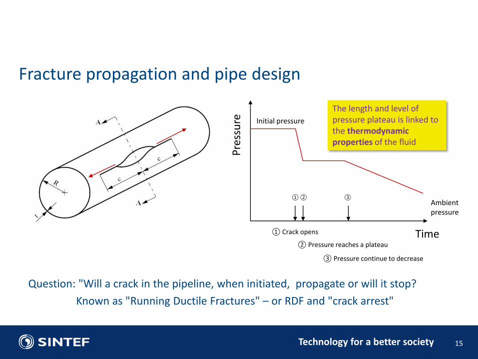
Fracture propagation and pipe design
Time P
ress
ure
① Crack opens
② Pressure reaches a plateau
③ Pressure continue to decrease
① ② ③
Initial pressure
Ambient pressure
Technology for a better society
Question: "Will a crack in the pipeline, when initiated, propagate or will it stop?
Known as "Running Ductile Fractures" – or RDF and "crack arrest"
15
Fracture propagation and pipe design
Time P
ress
ure
① Crack opens
② Pressure reaches a plateau
③ Pressure continue to decrease
① ② ③
Initial pressure
Ambient pressure
The length and level of pressure plateau is linked to the thermodynamic properties of the fluid

Technology for a better society 16
CO2 phase behaviour – rapid pressure release – isentropic
① ② ③

Technology for a better society 17
CO2 phase behaviour with precence of impurities
Vapour Liquid

Technology for a better society 18
CO2 phase behaviour with precence of impurities
Isentropic expansion

Technology for a better society 19
CO2 pipeline operational envelope (Pressure – Entropy)
Technology for a better society
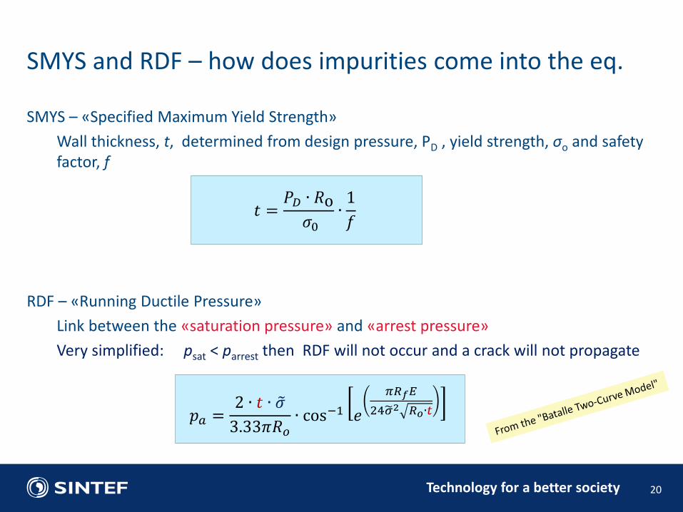
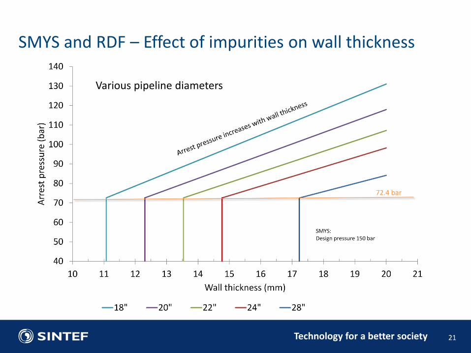
SMYS – «Specified Maximum Yield Strength»
Wall thickness, t, determined from design pressure, PD , yield strength, σo and safety factor, f
RDF – «Running Ductile Pressure»
Link between the «saturation pressure» and «arrest pressure»
Very simplified: psat < parrest then RDF will not occur and a crack will not propagate
20
SMYS and RDF – how does impurities come into the eq.
𝑡 =𝑃𝐷 ∙ 𝑅o 𝜎0
∙1
𝑓
𝑝𝑎 =2 ∙ 𝑡 ∙ 𝜎
3.33𝜋𝑅𝑜∙ cos−1 𝑒
𝜋𝑅𝑓𝐸
24𝜎 2 𝑅𝑜∙𝑡
Technology for a better society 21
SMYS and RDF – Effect of impurities on wall thickness
Various pipeline diameters

Technology for a better society 22
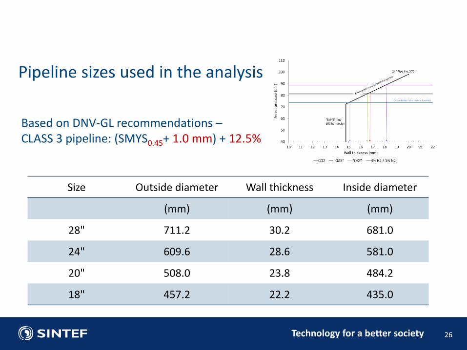
SMYS and RDF – Effect of impurities in a 24" pipeline

Technology for a better society 23
SMYS and RDF – how does impurities come into the eq.
+ 3.3 mm

Technology for a better society 24
SMYS and RDF – how does impurities come into the eq.
+ 3.3 mm
> 25 000 ton of steel (500 km)
Technology for a better society 25
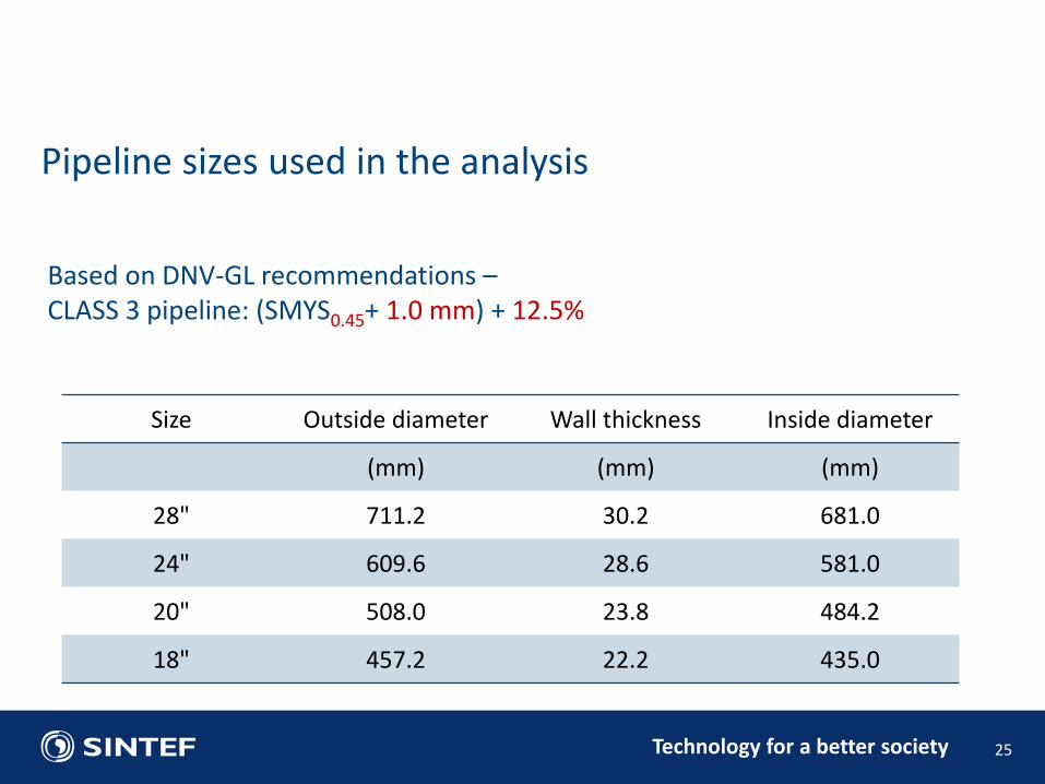
Pipeline sizes used in the analysis
Size Outside diameter Wall thickness Inside diameter
(mm) (mm) (mm)
28" 711.2 30.2 681.0
24" 609.6 28.6 581.0
20" 508.0 23.8 484.2
18" 457.2 22.2 435.0
Based on DNV-GL recommendations – CLASS 3 pipeline: (SMYS0.45+ 1.0 mm) + 12.5%
Technology for a better society 26
Pipeline sizes used in the analysis
Size Outside diameter Wall thickness Inside diameter
(mm) (mm) (mm)
28" 711.2 30.2 681.0
24" 609.6 28.6 581.0
20" 508.0 23.8 484.2
18" 457.2 22.2 435.0
Based on DNV-GL recommendations – CLASS 3 pipeline: (SMYS0.45+ 1.0 mm) + 12.5%

Technology for a better society 27
Possible path for pipeline pressure loss – principle
Isothermal Adiabatic With ambient heat exchange
CO2/N2/O2 - 4% impurity
Pressure loss from 150 to 90 bar
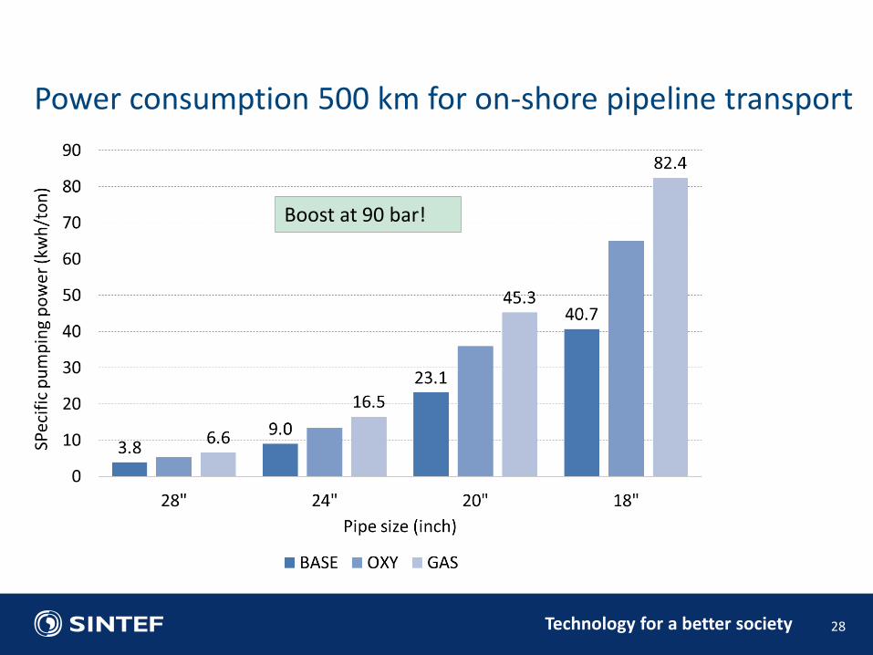
Technology for a better society 28
Power consumption 500 km for on-shore pipeline transport
Boost at 90 bar!

Technology for a better society 29
Power consumption 500 km for on-shore pipeline transport
Boost at 90 bar!
+83%
Technology for a better society 30
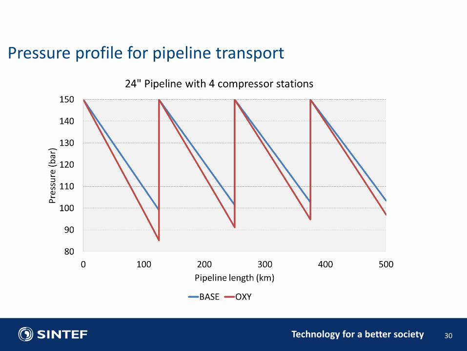
Pressure profile for pipeline transport

Technology for a better society 31
Temperature profile along a 24’’ pipeline
Technology for a better society 32
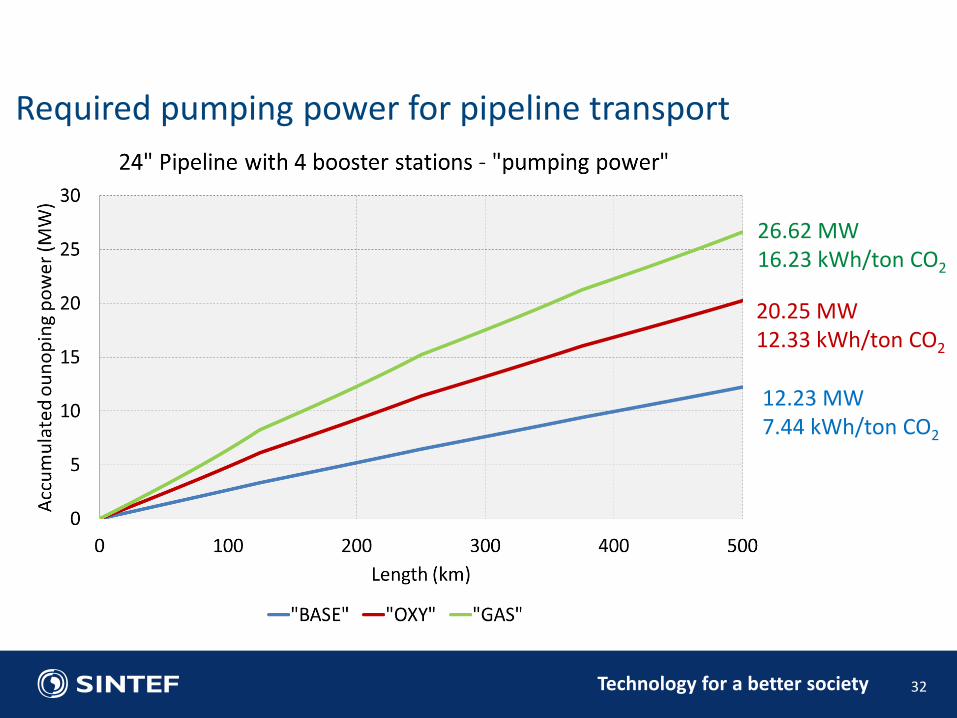
Required pumping power for pipeline transport
12.23 MW 7.44 kWh/ton CO2
20.25 MW 12.33 kWh/ton CO2
26.62 MW 16.23 kWh/ton CO2

Technology for a better society 33
CO2 conditioning cost of the BASE, OXY and GAS cases, €/tCO2

Technology for a better society 34
CO2 transport cost of the BASE, OXY and GAS cases, €/tCO2
Technology for a better society 35
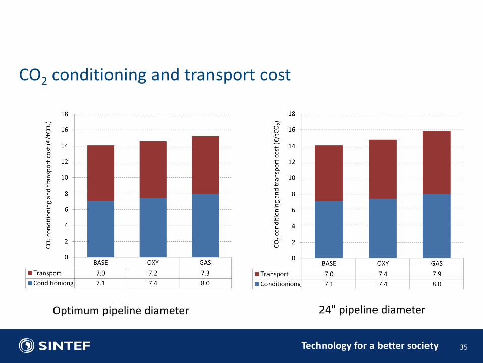
CO2 conditioning and transport cost
Optimum pipeline diameter 24" pipeline diameter

Technology for a better society
• Pipeline transport of CO2 over 500 km
• The results show that with 4% impurities from N2 and O2, the transport power consumption in a 24’’ pipeline configuration can increase by 100%
• to boundary conditions and need to be optimized on a case to case basis
• The most important thermodynamic property is the density.
• Pipe design
• It was shown how the cricondenbar for the transported fluid, combined with the possible operational envelope for the transport and the material properties for the pipeline should be used when evaluating the potential for RDF
• Economics:
• The results showed a cost increase of 8.5% annually for conditioning and transporting CO2 with impurities in a pipeline optimized for pure CO2
36
Summary and conclusions

Technology for a better society
Acknowledgement: The research leading to these results has received funding from the European Community's Seventh Framework Programme (FP7-ENERGY-20121-1-2STAGE) under grant agreement n° 308809 (The IMPACTS project). The authors acknowledge the project partners and the following funding partners for their contributions: Statoil Petroleum AS, Lundin Norway AS, Gas Natural Fenosa, MAN Diesel & Turbo SE and Vattenfall AB.
37
Thank you for your attention!

Technology for a better society
Technology for a better society
38