Embed Size (px)
Citation preview

NASA TECHNICAL MEMORANDUM
NASA TM X-53274
July 30, 1965
T E C H N I Q U E S O F I M P L E M E N T I N G L A U N C H A U T O M A T I O N P R O G R A M S
( S A T U R N I B S P A C E V E H I C L E S Y S T E M )
by WILLIAM G. BODIE Astrionics Laboratory GPO PRICE S
CFSTI PRICE(S) $
NASA Hard copy (HC) h o
George C. Murshd Microfiche (M F) 5 7 ff 663 July 65 Space Flight Cente
Hants vi1 1 e, A lu bum \ \

TECHNICAL MEMORANDUM X-53274
TECHNIQUES OF IMPLEMENTING LAUNCH AUTOMATION PROGRAMS
(SATURN IB SPACE VEHICLE SYSTEM)
BY
William G. Bodie
George C. Marshall Space Flight Center Huntsville, Alabama
July 30, 1965
ABSTRACT __c_--"* -
This paper identifies the methods and equipment through which automa- I
tion is becoming a major factor in testing and launching Saturn IB space vehicles. The mer i t s of a digital guidance computer and its impact in extending automated checkout are s t r e s sed ; a l so a logical basis is established for computer and manual test control. Hardware and software elements of the automated system are de- scr ibed, and details pertaining to reliability are emphasized. A concluding ap- praisal suggests that automation wi l l play a n expanding role in future test and launch operations.
, :
NASA-GEORGE C. MARSHALL SPACE FLIGHT CENTER
NASA-GEORGE C. MARSHALL SPACE FLIGHT CENTER
TECHNICAL MEMORANDUM X- 53274
TECHNIQUES OF IMPLEMENTING LAUNCH AUTOMATION PROGRAMS
(SATURN IB SPACE VEHICLE SYSTEM)
Wil l iam G. Bodie
ELECTRICAL SYSTEMS INTEGRATION DIVISION ASTRIONICS LABORATORY
RESEARCH AND DEVELOPMENT OPERATIONS
TABLE OF CONTENTS
Page
SUMhIARY . . . . . . . . . . . . . . . . . . . . . . . . . . . . . . . . . . . . . . . . . . . 1
INTROD.UCTION . . . . . . . . . . . . . . . . . . . . . . . . . . . . . . . . . . . . . . . . I
EVOLUTION OF AUTOMATION IN THE SATURN VEHICLE SYSTEM . . . . I
THE GROUNDSYSTEM . . . . . . . . . . . . . . . . . . . . . . . . . . . . . . . . . . . 4
THE FLIGHT SYSTEM . . . . . . . . . . . . . . . . . . . . . . . . . . . . . . . . . . . 7
AUTOMATED SYSTEM SOFTWARE. . . . . . . . . . . . . . . . . . . . . . . . . . . 12 BENEFITS, DISADVANTAGES, AND PROJECTIONS . . . . . . . . . . . . . . . 14 REFERENCES . . . . . . . . . . . . . . . . . . . . . . . . . . . . . . . . . . . . . . . . . 16
LIST OF ILLUSTRATIONS
Figure Title Page
I.
2.
3.
4.
5.
6.
7.
Saturn I/IB Systems Development Breadboard Facility . . . . . . Saturn IB Launch System Signal Flow Diagram . . . . . . . . . . . ESE-Computer-Vehicle Functional Interface Diagram. . . . . . . Typical Stage Digital Data Acquisition System . . . . . . . . . . . . Remote Automatic Calibration System . . . . . . . . . . . . . . . . . Switch Selector Command System . . . . . . . . . . . . . . . . . . . . ATOLL Test Program Development. . . . . . . . . . . . . . . . . . .
3
4
6
9
10
11
13
iii

This report was prepared for presentation a t the 4th Annual Reliability and Maintainability Conference, Los Angeles , California, July 3 0 , 1965. Con- ference sponsors a r e the American Society of Mechanical Engineers, American Institute of Aeronautics and Astronautics, and Society of Automotive Engineers.
.
i v

L
.
TECHNICAL MEMORANDUM X- 53274
TECHNIQUES OF IMPLEMENTING LAUNCH AUTOMATION PROGRAMS
(SATURN IB SPACE VEHICLE SYSTEM)
SUMMARY
This paper identifies the methods and equipment throug&- which automa- tion is becoming a major factor in testing and launching Saturn IB space vehicles. The mer i t s of a digital guidance computer and its impact in extend.ing automated checkout are s t r e s sed ; a lso a logical basis is established f o r computer and manual test control. Hardware and software elements of the automated system are de- scr ibed, and details pertaining to reliability are emphasized. A concluding ap- praisal suggests that automation wi l l play a n expanding role in future test and launch operations.
INTRODUCTION
Automation contributes to vehicle reliability from manufacturing through prelaunch checkout. Because of the speed of the digital computer, more t ime is available f o r testing, fault analysis, investigation, and corrective action. As launch densities increase, conservation of vehicle checkout time will become m o r e urgent. The computer checkout system will significantly reduce the burden imposed upon the launch crews by multivehicle missions. It is the aim of this pape r , therefore, to present a broad picture of automation and the means f o r ob- taining reliability assurance in launch operations of the Saturn IB space vehicle system.
EVOLUTION OF AUTOMATION IN THE SATURN VEHICLE SYSTEM
Automation is not new to space vehicles or the associated checkout and launch equipment. Space vehicles have been launched fo r many years with auto- mated firing-command-through-liftoff sequences, time-based inflight event pro- graming, and computer calculated velocity and position parameters to achieve planned trajectories. While this degree of automation has existed a t least s ince

the days of the Redstone and Jupiter systems, important new concepts of automa- tion are evolving in the Saturn space vehicle programs.
The Saturn inertial guidance system is designed around a gyroscopically stabilized platform with accelerometers and a digital computer. Pr imary func- tions of the computer are: calculating velocity and position of the vehicle, using this data f o r computing the trajectory, and generating steering signals for the vehicle control system. The computer must a l so issue a cutoff signal to the propulsion system when mission velocity is achieved. An adaptive guidance technique is used so that mission success is possible with loss of one or more engines; that is , the computer optimizes flight trajectory fo r propellant con- servation. Analog computers are sufficiently accurate fo r many purposes, but do not provide the versatility required f o r guidance and mas ter control of space vehicles o r the degree of accuracy possible with a digital computer.
Versatility requirements and accuracy enhancement therefore led t o the use of a digital computer with the capability of performing a multitude of func- tions in addition to its guidance role. These include orbital checkout, response to flight path correction signals from the ground, inflight sequencing of events that formerly had been performed by an electromechanical program device, and automated prelaunch checkout of the guidance and control system. Digital com- puters are inherently more flexible and accurate than analog computers. This flexibility results from a data storage o r memory capacity which allows a pre- stored program to operate upon data from external sources . Thus, functions are changed by program changes instead of by rewiring patchboards o r making other hardware changes. This storage capability a l so resul ts in fewer ari thmetic units required to perform a given computation. Also, since integration can be performed by a series of additions and multiplications, integrator ari thmetic units are not required [ i] . Accuracy in electronic analog computers is limited by component tolerances to approximately 0.01 percent, whereas digital com- puter accuracies are independent of component tolerances and depend upon word length o r number of bits used to define a parameter [ 2 ] .
The inclusion of a digital computer on the Saturn vehicle necessitated installation of a ground based digital computer f o r checkout of the guidance and control system. With a l l the capabilities of the ground based computer available f o r tes t and checkout purposes, the concept evolved to extend computer opera- tions beyond the guidance and control system areas. Additional functions that have evolved a r e discrete and analog signal recording and display, measurement circuitry calibration, event programing fo r test and limited launch sequences, fuel temperature averaging calculations, and signal transmission between the launch control center ( LCC) and automatic ground station (AGCS) computers.
2
Incorporation of launch-critical interlocking circuitry does not appear to be feasible at present as this would greatly complicate an already complex pro- graming effort , make late changes to the system difficult, and degrade launch reliability. Considerable concern exists regarding the utilization of the com - puter as a launch sequence command element. Obviously, failures in the com- puter or auxiliaries could occur that would cause varying degrees of trouble, depending largely on t ime of occurrence. Electr ical support equipment (ESE) hardwire safing circuits have been provided to r e s to re the vehicle to a safe condition in the event of a 'computer o r auxiliary system failure.
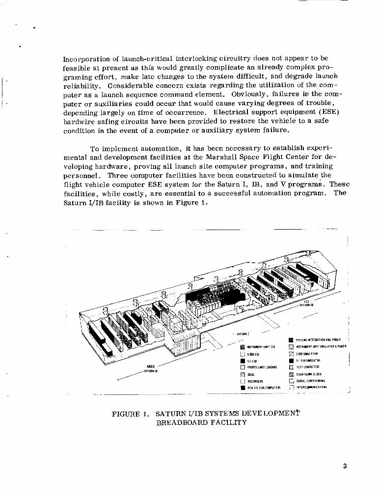
To implement automation, it has been necessary to establish experi- mental and development facilities at the Marshall Space Flight Center for de- veloping hardware , proving all launch site computer programs , and training personnel. Three computer facilities have been constructed to simulate the flight vehicle computer ESE sys tem for the Saturn I , IB, and V programs. These facilities , while costly, are essential to a successful automation program. Saturn I/IB facility is shown in Figure I.
The
APCS ' 0 PRORLUNT LOAMNG a TEST COYDUCTOR V
DDAS
FIGURE I. SATURN I/IB SYSTEMS DEVELOPMENT BREADBOARD FACILITY
3

The Saturn IB launch system is selected fo r specific description because its hardware and software are substantially defined and illustrate automation concepts f o r Saturn V. Figure 2.
Major elements of the automated system are shown in
AUTOMATIC GROUND Yd.DwIR?wd~ CONTROL STATION
LAUNCH CONTROL CENTER
* L
I IO1 I I I C IU GUIDANCE 8 STAB. PLATFORM C M STA. +
-4 SlVB ELEC. 8 MECH. C/O STATION 15 + W S I B ELEC 8 MECH C/O STATION
74-4 COMPUTER CONTROL STATION
11.1 1161 1 1 1 , MEASURING 8 TRACKING cm STATION
c
. .. .. ._ .. . . . - ,
L
1 TO
A.C.E. S Y S T E M ( M S C )
GSE DATA VEHICLE ANALOG AND DISCRETE DATA
~
P R O P E L L A N T L O A D I N G 8
FIGURE 2. SATURN IB LAUNCH SYSTEM SIGNAL FLOW DIAGRAM
THE GROUND SYSTEM
The RCA iiOA general purpose digital computer (system computer) was selected primarily to perform prelaunch checkout on the vehicle digital guidance system. It possesses a magnetic co re memory of 32,768 words. fastest computer available but it has been designed f o r the job. can recognize and respond to eight priority levels o r channels stimulated by automatic sensors o r manually operated switches 131. As a n example, the computer might be performing a hydraulic pump power-up sequence when a loss
It is not the The computer
4

. of control voltage occurs. The computer would be advised of this condition by a signal from the ESE and, through its priority interrupt feature, would shift its program to initiate power off command to the hydraulic pumps. Thus personnel and vehicle can be protected again-st uncontrolled engine movements. Another feature of pr ime importance is the data link section that ties the LCC and the AGCS computers together via coaxial cable. This link will be as long as six miles fo r the Saturn V launch complex. Signal t ransmission rate is approxi- mately 133,'OOO bits p e r second. An automatic parity bit e r r o r detection system is part of the link. In the event that a bit is lost , the sending computer will re- peat the message. Thus message transmission and receipt are safeguarded. Two computers are used for similarity of checkout and launch procedures with the Saturn V program. The LCC computer commands the AGCS computer to perform test programs and i ssue signals initiated from the ESE stations. How- e v e r , each computer may communicate with the other; i.e. , signal flow is bidirectional. Tes t programs are generally s tored in the AGCS computer; the LCC computer provides the interface link with launch operations personnel.
The digital events evaluator (DEE) is a system for scanning al l signifi- cant discrete events f rom the ESE or vehicle and p.rovides a r ea l t ime printout of changes on any of its 2160 input lines. An order-of-events program will be available to show deviations from planned sequencing of any event in the vehicle test or launch operations. The system del ivers its output pr imari ly by line p r in t e r , but a l so has paper tape o r magnetic tape recording capability. The function of monitoring significant discrete commands and indications during test and launch has, until recently, been performed by s t r i p chart recorders with approximately five milliseconds resolution. The DEE will provide typed copy with a time resolution of approximately two milliseconds. The main advantage over the old system is the reduction of t ime and effort required to examine and interpret the data.
The ESE performs several vital ro les - in automation although it is pri- mar i ly associated with manual techniques. First in importance, the ESE provides the means through which the computer operates and keeps launch-experienced personnel in command during test and launch operations (Fig. ' 3 ) . It a l so pro- vides flexibility of testing and the means fo r troubleshooting system problems that cannot feasibly be done with an automated system. The ESE provides signal distribution and conditioning of all discrete commands into and out of the system computer; provides signal isolation and filtering fo r cer ta in analog functions; reduces computer programing burden by incorporating function generation and network logic ; and, through hardwire connections, provides backup to the data link f o r those circuits essential to safing the vehicle. Two notable items of automated ESE are the launch and ignition sequencers. The launch sequencer

WSITIVE FORCE CMMC
I&#--
- -
PANEL
CONTROL ACCEL
YAW
a
,*, DDAS
ACCEL , YAW
FIGURE 3. ESE-COMPUTER-VEHIC LE FUNCTIONAL INTERFACE DIAGRAM
is energized at f ir ing command and performs switching to initiate numerous launch critical functions such as stopping LOX bubbling, power t ransfer , LOX and fuel lines ejection, and vehicle release. The device is driven from the count clock and automates launch operations f o r approximately 163 seconds before liftoff. It also commands the ignition sequencer to begin a program of start ing the eight engines. 100 milliseconds interval between s tar t ing pairs of diametrically opposed engines. The system computer could perform a l l these functions quite handily; because of i t s component count, however, it is not considered as reliable as this ESE. Unless a l l engines satisfy a minimum thrust requirement within three seconds a f t e r ignition command, cutoff will be given. single Saturn launch, the requirement that a l l engines produce adequate thrust before vehicle re lease significantly enhances the probability of mission success. The scope of this paper precludes definition of a l l ESE in the Saturn IB Program.
This hardware is designed to provide approximately
While cutoff has not m a r r e d a
6

L
Functional categories of ESE most closely associated with automation are shown on the system diagram of Figure 2. Figure 3 illustrates the relationship of the ESE and computer and shows some detail of the system elements.
Propellant loading and unloading operations are automated to a high degree. For safety and reliability, however, complete manual control is avail- able through the LCC stations. Automation is accomplished through a propellant tanking computer system (PTCS) for each propellant of both propulsion stages. It is a hybrid computer system in that analog and digital data are processed. The PTCS receives analog signals generated by vehicle tank level indicators. These signals are used by the PTCS to control bulk loading rates, t ime f o r activating cryogenic replenish control, and initiation of slow fill sequence for the RP-I tank, The RP-I tank is filled approximately two percent over mission requirements , and final level is adjusted by initiating level-adjust sequence in the launch countdown. The level adjust is accomplished through a drain valve controlled by the PTCS. All cryogenic propellants are maintained at I00 percent mission requirements by the replenishing valves o r , in the case of the LH,, a combination of slow bulk filling and replenishing valve action. The system checkout computer provides monitoring and display for this system and performs calculations based on RP-I temperature to co r rec t liftoff m a s s 141.
THE FLIGHT SYSTEM
The launch vehicle digital computer (LVDC) was required pr imari ly f o r t ra jectory optimization fo r propellant conservation, high accuracy, and mas te r control over vehicle functions during prelaunch checkout, launch, and orbital operations. The computer has two magnetic c o r e memories which may be used in parallel or series. The parallel arrangement may be used with a selection network to provide higher reliability, o r the memories may be used serially to provide more s torage capacity. Triple modular redundancy is utilized in the logic portion of the computer so that one spurious output o r the failure of a single component wiil not affect the output signal. This is accomplished through majority voting ( two out of th ree inputs) establishing a t rue output signal. The computer may be commanded through the data adapter from the ground based digital com- mand system to interrupt its p roba rn and perform priority instructions, o r it may receive priority information from a flight sensor that can cause program alteration. When the instructions have been performed, it will resume the interrupted program. A few of the operations that the computer may perform are: computer self-test, mission simulation, telemetry check, stabilized plat- form performance monitoring, steering command generation, event sequencing,

and S-IVB engine r e s t a r t a t the proper t ime f o r spacecraft injection into a lunar trajectory. The launch vehicle data adapter ( LVDA) provides signal conditioning fo r a l l signals from the computer to the controlled equipment, provides. temporary data s torage, performs e r r o r monitoring and detection, and controls the inputs to the LVDC. It utilizes triple modular redundant circuits in several vital sub- systems to achieve high reliability. In short , it functions as the interface unit between the LVDC and a l l systems associated with it [ 51.
The ground station s to re s the data received in magnetic co res and makes the data available to the ground computer upon request [ 3 , 61. After liftoff the s a m e information is transmitted by an R F PCM/FM transmitter. All significant ve- hicle analog data other than vibration and acoustic measurements are converted to digital values and transmitted to earth through the system. On the Instrument Unit, approximately 288 out of 315 transmitted signals a r e included on the DDAS. Thus the DDAS is the pr imary information system fo r automated and manual checkout. Many of the measurements applied to the PCM/FM sys- tem are a l so applied to the FM/FM system to give higher reliability through redundancy. Perhaps the most significant capability of the PCM/ FM ground- computer system is that inflight data can be received and displayed on a real t ime basis. Real time display is achieved through the s ix cathode ray tubes and ESE control stations located i n the LCC. therefore have the capability of detecting anomalies as soon as they occur (F ig . 4).
I
l
Launch operations personnel will
I
Automation will be most useful in checkout of the vehicle measuring I systems as there are well over 1300 measurements planned fo r the Saturn IB.
Some of the transducers used are: force balance accelerometers f o r s t ructural bending; bourdon tube potentiometers for p re s su re : therm i s t o r s , thermocouples, and resistance thermometers fo r temperathres: piezoelectric acceleronieters fo r vibration; capacitance probes f o r liquid levels; potentiometers f o r position; and flowmeters for flow r a t e s 171. Each measurement signal conditioning
8

. 4
600 ItHzIFM DATA TO GROUND RCV. STATION
r
* PCMIDDAS e-
ASSEMBLY
I .
AMPLITUDE MODULATED
PULSE
DATA
MULTIPLEXER
3600 PPS 30 CHANNELS INTERNAL (MUXI
CLOCK
SYNC SIGNAL
1 ANALOG DATA'
0-5 VOLTS
REMOTE DIGITAL
12 TISECOND SAMPLE RATE
DISCRETE' AND DIGITAL DATA
FUNCTIONS /
1. SCANNING MUX OUTPUTS (PAM DATA)-COMBINING ALL INTO ONE PAM WAVETRAIN
2. ANALOG TO DIGITAL CONVERSlON AND ENCODING
3. DATA IDENTIFICATION CODE GENERATION AND WORD ARRANGEMENT
4. GENERATES 600 kHzCARRlER FOR DDAS OUTPUT, AND OUTPUT TO PCM/FM RF TRANSMITTER
5. GENERATES SYNCHRONIZING PULSES FOR MULTI- i PLEXERS AND SUEMULTIPLEXERS
24-27 NOT SUBMULTIPLEXED-HIGH SPEED SWEEP-SAMPLE RATE 120 T/SECOND
I2e-30 NOT USED FOR DATA
FIGURE 4. TYPICAL STAGE DIGITAL DATA ACQUISITION SYSTEM
circui t must be verified near launch time to assure the validity of flight data. This check is performed through'the remote automation calibration system (RACS) (Fig. 5 ) . It consists of a ground control station connected by hardwire through each stage umbilical t o a measuring selector control package on the stage. The measuring selector is connected to the measuring r ack , which is connected to the transducers. As many as 27 of these with 20 measurements p e r unit may be accommodated by one selector control package. Any measure- ment circuit may be selected from the ground control station in high o r low range. Circuitry and switching provisions are included in the measuring racks t o simulate the transducers ' outputs at the high and low points of their calibration curves. These simulated transducer outputs are fed into a n amplifier and con- ve r t ed to a signal level (usually 0 to 5 volts) compatible with the. DDAS system. The ent i re operation can be performed by the ground system computer. c,omputer can also compare the measured values with prestored data and display the resul ts including out-of-tolerance values a t control stations in the LCC.
The
9

Q RACS TEST PROGRAM
13 BIT BINARY WORD L
r
COMPUTER Y GROUND CONTROL
ESE
(1) MEASUREMENT SELECTION
aHI -LO SELECTION
YEASUREY€NT SELECTOR
'I UEASURIMG R M
(21 HI-LO SWITCHING
(3) SlGNAL CONDITIONING (TMNWJCER W U L A T I W
rmMsuucm
TYPICAL STAGE W S
FIGURE 5. REMOTE AUTOMATIC CALIBRATION SYSTEM
Thus the RACS system is highly compatible with computer controlled checkout and provides for testing approximately 60 percent of the measurement c i rcui ts in a matter of minutes. Many of the measurements do not require signal con- ditioning and hence are not a par t of the RACS. tem computer via DDAS, however, and therefore may be displayed and recorded in various subsystem tests and the launch sequence.
These are available to the sys-
The switch selector provides the means for m a s t e r control of each stage from the LVDC (Fig. 6 ) . From liftoff to orbital injection, approximately 88 commands from the LVDC are decoded and channeled to operating components by the switch selector, Some typical command functions are: f i r ing stage separation initiators , f i r ing retrorockets , star t ing S-NB engine , jettisoning the launch escape tower , and engine cutoff. The switch se l ec to r ' s binary decoding capability reduces substantially the connectors and wiring required throughout the vehicle. Each switch selector has a capacity of 112 individual output com- mands; these a r e selected by an eight bit binary word from the LVDC. Before any output gate is opened, the LVDC examines a verification word from the input regis ter and determines whether the co r rec t word was set into the input register.
10

I U SWITCH SELECTOR PpNEL
gFUNCT\OW ENCODE f READ (EXECUTE)
STAGE SELECTION 8 SW SEL. RESET
TEST PRO6RAUS
u)
I N T E W L POWER ON - I- 4 INPUT REGISTER VERIFY- U ij STAG€ SELECTED E
- M E R TRANSLATES (ON-OFF) SIGNALS
CHANNEL MONITOR
FIGURE 6. SWITCH SELECTOR COMMAND SYSTEM
If not, the LVDC will issue a re se t command to res tore the input register to its initial condition. The LVDC will then issue the binary complement of the original word and gate the same channel the original word would have gated under normal c i rcumstances. This word verification check and the ability of the switch selec- tor to issue the same command from the word complement greatly enhance event programing reliability. Redundancy is used in the design of the switch se lec tor and its hardwire link to the LVDA. Commands to the input register and register verification lines are through separate connectors; dual re lays are used fo r stage se lec t , r e se t , and output gating commands. One set of command hardwires will be provided fo r control of vehicle function during checkout and launch. Thus, through the Instrument Unit stage umbilical, a maximum of 112 events can be controlled on each stage from the ESE and ground system computer with only 22 hardwires. One hardwire control panel will exist in the LCC and severa l other command stations will have access to the control lines through the system com- puter.

AUTOMATED SYSTEM SOFTWARE 16, 81
I 12
Approximately 80 computer test programs are planned f o r the ea r ly launches of the Saturn IB space vehicle. In addition to these, somh 40 opera- tional programs will be required to guide the computer through a l l the operations necessary to perform the test programs. Operational programs control o r manage the overall operation of the computer; tasks such as a priority interrupt, causing data to be read in from magnetic tape to memory; computer self-test; and data link control are examples (Fig. 3) . Operational programs do not change and may be thought of as an integral par t of the computer. Tes t programs are designed to perform precise functions on specific hardware; as the hardware changes, so must the test program change (F ig . 3 ) . Computer tes t programs fo r the first launch are associated primarily with the LVDC/LVDA , stabilized platform , flight control system, switch selector , propellant loading, measuring sys t em, and emergency detection system (EDS). Examples of tes t programs in each sys t em, respectively, are: simulated flight, LVDC switch selector t e s t , and LVDC/LVDA discrete output test; accelerometer monitor and azimuth laying; S-IB A, gain test and S-IB overall steering tes t ; system computer switch selector channel test; propellant loading and monitoring; DDAS/RACS calibration; and engine out abort test [ 91 .
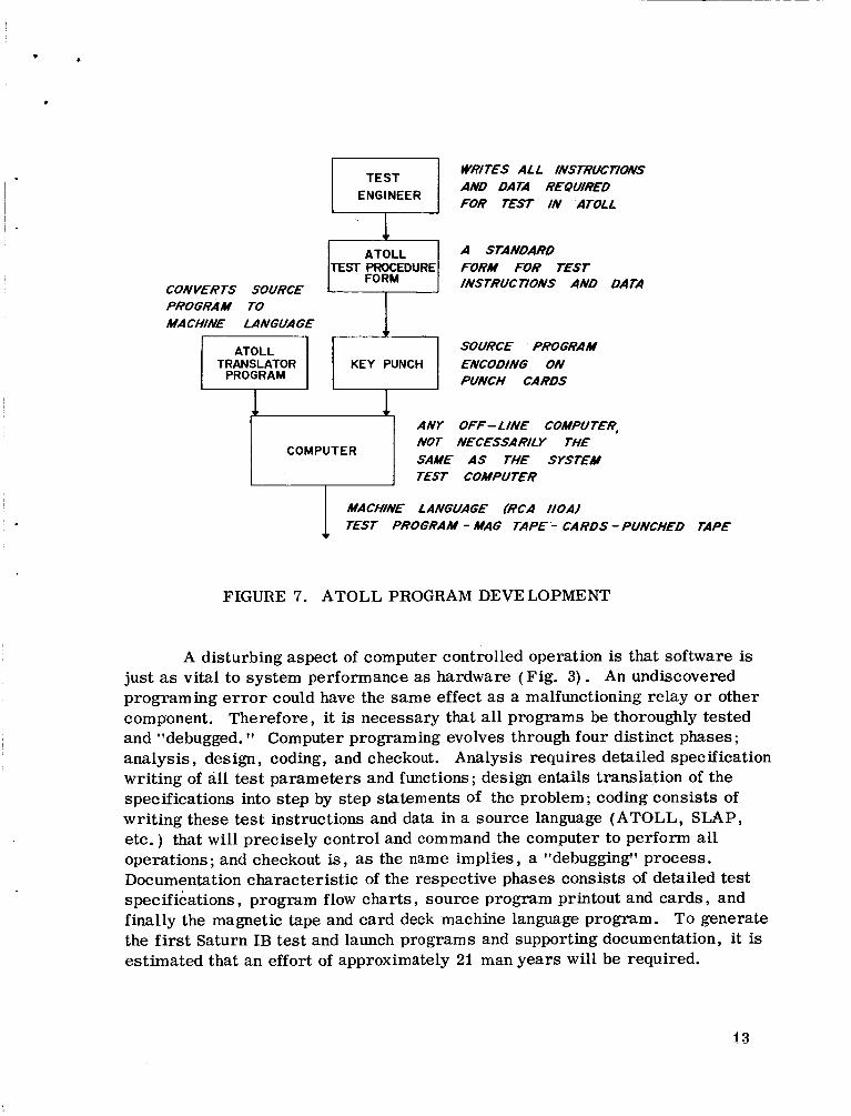
Although many computer language systems ex is t , no single system was suitable fo r the numerous government and contractor-owned computer tes t facilities involved in qualifying a l l stages of the Saturn vehicle. It is axiomatic that the reliability attained in the Saturn program has been the result of a rig- orous checkout program executed by personnel experienced in manual checkout techniques. It is to utilize this s to re of experience and to exercise compre- hensive test program control that a common problem-oriented language is being developed. The language must be understandable in t e r m s of manual checkout techniques, computer translatable into the system computer/machine language , and comprehensive to implement the multitude of instructions necessary to per- form the tests. This system f o r tes t engineer/computer communication has been assigned the acronym ATOLL fo r acceptance , test, or launch language. Mnemonic symbols are used that generally are logical derivations of the func- tions to be performed. Most operator functions are defined by four cha rac t e r s such as BEGN for BEGIN, EXEC fo r EXECUTE, DISI f o r DISCRETE IN, ALGE fo r ALGEBRAIC COMPUTATION, etc. ATOLL is not as yet sufficiently de- veloped to implement many launch checkout programs; thus another m o r e de- tailed language system , symbolic language assembler program (SGAP), will be used f o r most programs fo r the first Saturn IB launch. The goal is ATOLL, however, and more tests will employ it as development progresses . procedure fo r preparing ATOLL test programs is shown in Figure 7.
The general
CONVERTS SOURCE PROGRAM TO MACHINE LANGUAGE
ATOLL TRANSLATOR
PROGRAM
1 r-1 ANY
WRITES ALL IffSTRUC77OiV.S AND DATA R€QU/R€D FOR EST IN ATOLL
A STANDARD FORM FOR T€ST INSTRUC77ONS AND DATA
SOURCE PROGRAM ENCODING ON PUNCH CARDS
OFF- L /NE COMPUT€R, NECESSA RILY THE Nor
SAME AS THE SYSTEM COMPUTER
TEST COMPU T€R
MACHINE LANGUAGE /RCA IIOA/ TEST PROGRAM - MAG TAPE - CARDS -PUNCHED TAPE
FIGURE 7. ATOLL PROGRAM DEVELOPMENT
A disturbing aspect of computer controlled operation is that software is just as vital to system performance as hardware (Fig. 3 ) . An undiscovered programing e r r o r could have the same effect as a malfunctioning relay o r other component. Therefore, it is necessary that a l l programs be thoroughly tested and "debugged. Computer programing evolves through four distinct phases; analysis, design, coding, and checkout. Analysis requires detailed specification writ ing of all tes t parameters and functions; design entails translation of the specifications into s tep by s tep statements of the problem; coding consists of writ ing these test instructions and data in a source language (ATOLL, SLAP, etc. ) that will precisely control and command the computer to perform a l l operations; and checkout is, as the name implies, a lldebuggingll process. Documentation characterist ic of the respective phases consists of detailed test specifications, program flow charts , source program printout and ca rds , and finally the magnetic tape and card deck machine language program. To generate the first Saturn IB tes t and launch programs and supporting documentation, it is estimated that an effort of approximately 21 man years will be required.
13
.
BENEFITS, DISADVANTAGES, AND PROJECTIONS
The tremendous speed of the digital computer has revolutionized repeti- tive industrial processes but kyis not advanced space vehicle launch schedules. The t ime required fo r individual tests has been reduced but more testing is being done [ 61 . More testing inevitably produces more reliable flight vehicles. Thus, automated techniques are providing the basis f o r higher reliability. Day- to-day tests in factory checkout provide data f o r determining component parame- ter variation, Librar ies of test records may be s tored on magnetic tape or typed copy in a fraction of the space required fo r s t r ip chart records. Auto- mated techniques facilitate solutions to problems because of the immediate availability of tes t resu l t s on typewritten copy [ 61. Through rapid distribution of test data, all organizational elements concerned may simultaneously focus upon problem areas. Errors in interpretation and transposition are completely eliminated. Analysis of the data is much easier than extracting data from s t r i p chart records. The data are a lso more accurate. Repeatability and accuracy are positive factors fo r computer controlled tests. The ttcannedTt tests are all the same , and any deviation in results between tests would incriminate the tested system ra ther than lead to speculation regarding what, when, and how human operators had introduced a stimulus and observed a result , Automated test programs will provide significant t ime savings in redundant circuit verification as redundancy is extensively used for reliability enhancement in the flight con- t rol computer, the EDS ra te gyros, and the LVDC. Real t ime display of flight performance parameters should prove to be of substantial value in analyzing various flight system failures and correct ing spatial attitudes during orbital maneuvers.
Obviously automation is not the solution to a l l test and checkout problems. Some definite disadvantages must be recognized. Training of personnel to ef- fectively use automated techniques is a substantial and continuing task. New organizations o r contracts must be established to provide programing and docu- mentation services . Flexibility of testing is' somewhat res t r ic ted because the cost-to-benefits ratio for nonrepetitive testing is too high. The high speed capability of the computer makes it susceptible to system noise, necessitating the yse of signal conditioners fo r low level analog hardwire data. Finally, the automated system is new and therefore must be t rea ted with considerable re- se rve as a major launch command element.
14

All the capabilities of the ground system computer are not presently being used in the launch sequence. This is consistent with the basic concept of relia- bility. Only t ime and operating experience can provide the basis f o r establishing full confidence in the system computer as a major launch command element. Thus the Saturn launch system is designed to use the computer and ESE to pro- vide maximum flexibility and safety in launch operations. As the computer sys- tem proves its reliability, and system hardware and software engineers get a better ynderstanding of what should be automated, greater use will be made of the computer. As with any new concept, change evolves gradually and the first steps are the longest. Some possibilities fo r future computer operations are: utilization of the function generation capabilities of the computer to apply r amp function stimuli t o the guidance and control system components; elimination of many analog recorders used fo r currents, voltages, and t ransducer measurements; absorption of some ESE event logic chains; p re s su re switch calibration; and RACS flight verification of measurement transducers.

REFERENCES
1.
2.
3.
4.
5.
6.
7.
8.
9.
16
Leondes, C. T. , Computer Control Systems Technology, McGraw-Hill Book Co. , Inc. , N. Y . , London, Toronto, 1961, Ch. I.
Karplus, W. J. , The Nature of Analog Computations Short Course, 1964, Introduction to Modern Engineering Application of Computer Control System Technology).
(Notes U. C. L. A.
MSFC Automation Plan, Technical Staff MSFC Automation Board, June I , 1964.
Saturn IB Electrical Ground Support Equipment for Launch Complex 34, Launch Support Equipment Engineering Division, KSC, December 21, 1964.
Instrument Unit Model Specification Saturn IB/V Launch Vehicle, MSFC, R-ASTR/R-P&VE.
Software for IU-201 at MSFC, SA-201 at KSC, SA-501 at KSC, MSFC Re- search and Development Operations, December i , 19G4.
Saturn I, Block I1 Instrunientation System Description, MSFC Conimunication and Instrumentation Division/Chrysler Corporation, Space Division, Hunts- ville Operations, August 15, 19G4.
Launch and Checkout Computer Program Configuration and Control Plan, Revision B, MSFC Automation'Suls-Board No. 4, October 26, 1964.
Specifications for t h e Test Programs for the Saturn IB/V Launch Computer Complex, IBM Huntsville Facility Space Guidance Center , April 20 , 1965.

NASA TM X-53274 APPROVAL
TECHNIQUES OF IMPLEMENTING LAUNCH AUTOMATION PROGRAMS
(SATURN IB SPACE VEHICLE'SYSTEM)
By William G. Bodie
The information in this report has been reviewed fo r security classifica- tion. Review of any information concerning Department of Defense o r Atomic Energy Commission programs has been made by the MSFC Security Classifica- tion Officer. This report , in its entirety, has been determined to be unclassified.
This document has a l so been reviewed and approved for technical accuracy.
- -
R. ADEN Chief, Electrical Support Equipment Branch
H. FICHTNER Chief , Electrical Systems Integration Division
W. HAEUSSERMANN Director , Astrionics Laboratory
17

DISTRIBUTION
DIR Dr. von Braun
I-DIR Gen. O'Connor/Mr. Hueter
I-I/IB-DIR Col. J a m e s ( 3)
I- I/ IB-E Mr. Vruels
I- I/ IB- P Mr. Pikes
I- I/ IB- U Mr. Simmons
I- I/ IB- F Mr. Cooper
I-V-G Mr. S. E . Smith
I-MICH-MGR Dr. Constan Mr. Stamy Mr. Rougon
I-SE-CH Dr. Mrazek
K-DIR Dr. Debus
K-D Mr. Poppel
K-E Mr. Sendler
K-FA Mr. Dodd
K-P Mr. Claybourne
K-VG Mr. Rigel1 ( 2 )
K-VG2 Mr. Greenfield
K-VG45 Mr. T e r r y
K- DT Mr. Brewster
LVO-E Mr. Williams
R-DIR Dr. McCall
R-AERO Dr. Geissler/Mr. 0. C. Jean Dr. Speer
R-ME-DIR Mr. Kuers
R-P& VE -DIR M r . Cline
R- P& VE -AA Mr. Galzerano
R-P&VE-P Mr. Paul Mr. Voss
18

DISTRIBUTION ( Cont'd)
R-P& VE -V Mr. Palaoro Mr. Glover Mr. McCullough Mr. Faulkner Mr. Thrower Mr. Kistler Mr. Schulze Mr. Prasthofer
R-QUAL-DIR Mr. Grau
R-QUAL-A Mr. Henritze
R-QUAL-P Mr. Brooks
R-QUA L-TS Mr. Klauss
R-QUAL-OE Mr. Lockridge Mr. Boddie
R-RE L-DIR Mr. Schulze
R-RP-DIR Dr. Stuhliager
R-TEST-M Dr. Sieber
R-TEST-T Mr. Driscoll
R-ASTR-DIR Dr. Haeussermann/Ref. Fi le Mr. Richard IvIIss F!~*t/ers
R-ASTR-A Mr. Digesu/Mr. Thornton
R-ASTR-E Mr. Fichtner Mr. Youngblood Mr. Bennett
R-ASTR-EA Mr. Smith Mr. Paschal Mr. Ful ler Mr. Felch
R-ASTR-ES Mr. Aden Mr. Baggs Mr. Burdine Mr. White Mr. Milner Mr. Glass M r. Woodruff Mr. Cole Mr. Haley Mr. Barr Mr. Robinson Mr. Goodhue Mr. Gallaher Mr. Bodie (15)
R-ASTR-F Mr. HosenthiedMr. Blackstone
R-ASTR-G Mr. Mandel Mr. Wood
R-ASTR-I Mr. Hoberg
19

R-ASTR-M M r . Boehm
R-ASTR-N M r . M o o r e Mr . Wojtalik
R-ASTR-NG M r . F. A . Winkler
R-ASTR-ND M r . T u r n e r
R-ASTR- T J M r . B r a n d n e r ( 2 )
R-ASTR-U M r . W e b e r M r . P a y n e M r . C a g l e
DISTRIBUTION ( Concluded)
I-sc M r . R e i n a r t z
I-SC-B M r . C h a m b e r s
MS-IPL ( 8 )
MS-IP
MS-H
1-RM-M
cc-P
Scient i f ic a n d Techn ica l Informat ion Fac i l i t y (25)
Attn: NASA Represen ta t ive (S-AK/RKT) P. 0. Box 5700 B e t h e s d a , Maryland
20