Embed Size (px)
Citation preview

Technical�training.Product�information.
BMW�Service
F80/F82�Complete�Vehicle
General�information
Symbols�used
The�following�symbol/schematic�diagram�is�used�in�this�document�to�facilitate�better�comprehensionor�to�highlight�very�important�information:
Contains�important�safety�information�and�information�that�needs�to�be�observed�strictly�in�order�toguarantee�the�smooth�operation�of�the�system.
Information�status�and�national-market�versions
BMW�Group�vehicles�meet�the�requirements�of�the�highest�safety�and�quality�standards.�Changesin�requirements�for�environmental�protection,�customer�benefits�and�design�render�necessarycontinuous�development�of�systems�and�components.�Consequently,�there�may�be�discrepanciesbetween�the�contents�of�this�document�and�the�vehicles�available�in�the�training�course.
This�document�basically�relates�to�the�European�version�of�left-hand�drive�vehicles.�Some�operatingelements�or�components�are�arranged�differently�in�right-hand�drive�vehicles�than�shown�in�thegraphics�in�this�document.�Further�differences�may�arise�as�a�result�of�the�equipment�specification�inspecific�markets�or�countries.
Additional�sources�of�information
Further�information�on�the�individual�topics�can�be�found�in�the�following:
• Owner's�Manual• Integrated�Service�Technical�Application.
Contact:�[email protected]
©2014�BMW�AG,�Munich
Reprints�of�this�publication�or�its�parts�require�the�written�approval�of�BMW�AG,�Munich
The�information�contained�in�this�document�forms�an�integral�part�of�the�technical�training�of�theBMW�Group�and�is�intended�for�the�trainer�and�participants�in�the�seminar.�Refer�to�the�latest�relevantinformation�systems�of�the�BMW�Group�for�any�changes/additions�to�the�technical�data.
Information�status:�March�2014BV-72/Technical�Training

F80/F82�Complete�VehicleContents1. Introduction.............................................................................................................................................................................................................................................1
1.1. M�history..............................................................................................................................................................................................................................21.1.1. E30�M3� ...............................................................................................................................................................................................21.1.2. E36�M3.................................................................................................................................................................................................41.1.3. E46�M3.................................................................................................................................................................................................61.1.4. E90/E92/E93�M3...................................................................................................................................................................8
1.2. F80�M3�vehicle�profile...............................................................................................................................................................................101.3. F82�M4�Coupe�vehicle�profile......................................................................................................................................................11
2. Technical�Data...............................................................................................................................................................................................................................132.1. Garage�dimensions.........................................................................................................................................................................................132.2. Comparison�of�technical�data�in�BMW...........................................................................................................................14
2.2.1. BMW�EfficientDynamics�measures....................................................................................................162.3. BMW�M3�and�M4�Coupe�compared�to�competitors.................................................................................17
2.3.1. M3.............................................................................................................................................................................................................172.3.2. M4�Coupe....................................................................................................................................................................................18
3. Body..................................................................................................................................................................................................................................................................193.1. Bodyshell........................................................................................................................................................................................................................19
3.1.1. Chassis�and�suspension�components�and�rigidity�concept.........................193.2. Exterior� .............................................................................................................................................................................................................................21
3.2.1. Front�view.....................................................................................................................................................................................213.2.2. Side�view.......................................................................................................................................................................................233.2.3. Rear�fender�and�rear�view� ................................................................................................................................273.2.4. Trunk� lid...........................................................................................................................................................................................283.2.5. Underbody�and�thermal�protection� ...................................................................................................29
3.3. Interior..................................................................................................................................................................................................................................303.3.1. Driving�area�and�steering�wheel...............................................................................................................303.3.2. Leather�trim...............................................................................................................................................................................313.3.3. Seats....................................................................................................................................................................................................323.3.4. Doors�and�decorative�strips� ..........................................................................................................................33
4. Powertrain..............................................................................................................................................................................................................................................344.1. Engine�S55B30T0� .........................................................................................................................................................................................344.2. Transmission.............................................................................................................................................................................................................34
4.2.1. Manual�gearbox...................................................................................................................................................................344.2.2. Clutch..................................................................................................................................................................................................364.2.3. M�double-clutch�transmission�(M�DCT)�with�Drivelogic.....................................364.2.4. Structure�and�power�flow...................................................................................................................................384.2.5. Technical�data�of�M�DCT.....................................................................................................................................434.2.6. System�information.......................................................................................................................................................44
F80/F82�Complete�VehicleContents
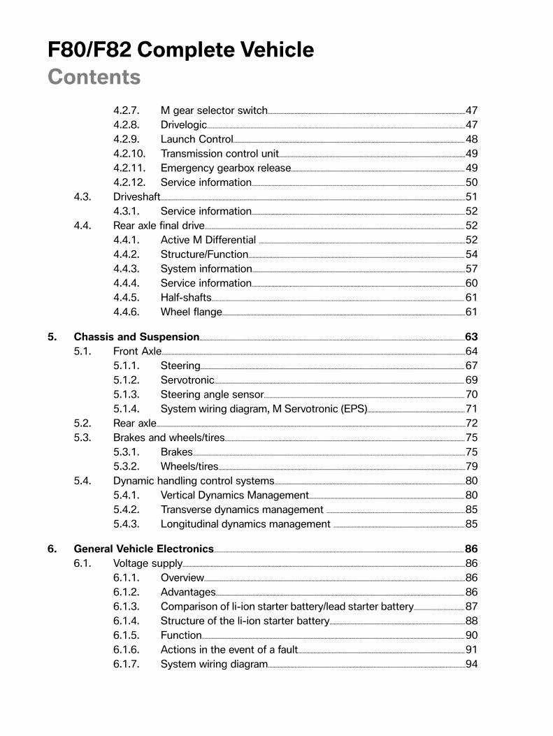
4.2.7. M�gear�selector�switch............................................................................................................................................474.2.8. Drivelogic.......................................................................................................................................................................................474.2.9. Launch�Control....................................................................................................................................................................484.2.10. Transmission�control�unit....................................................................................................................................494.2.11. Emergency�gearbox�release...........................................................................................................................494.2.12. Service�information.......................................................................................................................................................50
4.3. Driveshaft........................................................................................................................................................................................................................514.3.1. Service�information.......................................................................................................................................................52
4.4. Rear�axle�final�drive........................................................................................................................................................................................524.4.1. Active�M�Differential� ..................................................................................................................................................524.4.2. Structure/Function.........................................................................................................................................................544.4.3. System�information.......................................................................................................................................................574.4.4. Service�information.......................................................................................................................................................604.4.5. Half-shafts...................................................................................................................................................................................614.4.6. Wheel�flange............................................................................................................................................................................61
5. Chassis�and�Suspension............................................................................................................................................................................................635.1. Front�Axle.......................................................................................................................................................................................................................64
5.1.1. Steering...........................................................................................................................................................................................675.1.2. Servotronic.................................................................................................................................................................................695.1.3. Steering�angle�sensor..............................................................................................................................................705.1.4. System�wiring�diagram,�M�Servotronic�(EPS).....................................................................71
5.2. Rear�axle...........................................................................................................................................................................................................................725.3. Brakes�and�wheels/tires..........................................................................................................................................................................75
5.3.1. Brakes.................................................................................................................................................................................................755.3.2. Wheels/tires...............................................................................................................................................................................79
5.4. Dynamic�handling�control�systems.......................................................................................................................................805.4.1. Vertical�Dynamics�Management..............................................................................................................805.4.2. Transverse�dynamics�management� ..................................................................................................855.4.3. Longitudinal�dynamics�management� .............................................................................................85
6. General�Vehicle�Electronics.................................................................................................................................................................................866.1. Voltage�supply........................................................................................................................................................................................................86
6.1.1. Overview.........................................................................................................................................................................................866.1.2. Advantages................................................................................................................................................................................866.1.3. Comparison�of�li-ion�starter�battery/lead�starter�battery....................................876.1.4. Structure�of�the�li-ion�starter�battery................................................................................................886.1.5. Function..........................................................................................................................................................................................906.1.6. Actions�in�the�event�of�a�fault......................................................................................................................916.1.7. System�wiring�diagram............................................................................................................................................94

F80/F82�Complete�VehicleContents
6.1.8. Li-ion�starter�battery�in�Service.................................................................................................................956.2. Bus�overview� ..........................................................................................................................................................................................................976.3. On-board�information.............................................................................................................................................................................100
6.3.1. MDrive�menu......................................................................................................................................................................1006.3.2. M�instrument�cluster..............................................................................................................................................1046.3.3. Head‐Up�Display...........................................................................................................................................................1056.3.4. Active�Sound�Design� ...........................................................................................................................................1056.3.5. M�Lap�Timer�app� .......................................................................................................................................................106
7. Brief�Overview�of�Equipment........................................................................................................................................................................1077.1. F80/F82�standard�equipment....................................................................................................................................................107
7.1.1. Paint�colors............................................................................................................................................................................1077.1.2. Leather�colors...................................................................................................................................................................1087.1.3. Interior�trims.........................................................................................................................................................................108


F80/F82�Complete�Vehicle1.�Introduction
1
The�BMW�M�brand�is�expanding.�In�addition�to�the�current�BMW�M�models�(the�5-Series,�6-Series�andX�models),�for�the�first�time�there�is�also�a�BMW�M4�Coupe�with�the�introduction�of�the�fifth�generationof�the�new�BMW�M3�.
Similar�to�all�BMW�AG�vehicles,�the�BMW�M�Coupe�and�the�M�Convertible�body�variants�will�also�bemarketed�as�a�BMW�4-Series�in�order�to�clearly�distinguish�this�segment�from�the�Sedans.
The�"4"�in�the�type�plate�is�a�visual�indicator�of�how�different�the�new�BMW�M4�Coupe�is�to�the�BMWM3�4�door�Sedan�with�its�own�personality,�enhanced�sporting�character�and�more�exclusivity.
The�new�BMW�M4�Coupe�and�the�new�BMW�M3�in�the�fifth�generation�were�systematically�designedfor�lightweight�construction.�In�order�to�achieve�this�objective,�this�lightweight�construction�conceptwas�consistently�applied�in�the�body�area,�as�well�as�in�the�powertrain�and�chassis�and�suspension.A�composite�construction�with�different�material�combinations�is�used�in�the�body,�electrical�system,in�the�chassis�and�suspension�and�the�powertrain.�Metals�such�as�steel,�magnesium�and�aluminum,�aswell�as�the�use�of�plastics�and�fiber�composites,�are�used�alternately.
In�contrast�to�the�predecessor�where�a�high-speed�8-cylinder�naturally�aspirated�engine�was�used,�forthe�first�time�in�the�BMW�M3/M4�Coupe�an�engine�with�six�cylinders�and�turbocharging�is�used�as�apowertrain.
In�the�area�of�the�powertrain�concept,�the�BMW�M3�and�the�BMW�M4�Coupe�thus�pursue�the�samestrategy�as�their�big�brother�in�the�BMW�M�X-Series,�as�well�as�that�of�the�BMW�M5/M6,�whereturbocharged�engines�have�been�in�use�for�a�long�time.
This�combination�of�consistent�lightweight�construction�and�turbocharging�guarantees�that�power�andagility�are�exceptional�and�enhances�the�competitive�position�of�the�BMW�M3�and�BMW�M4�Coupe.
With�success�embedded�in�the�genes,�the�new�BMW�M4�Coupe�and�the�new�BMW�M3�in�the�fifthgeneration�will�celebrate�their�global�premier�in�June�2014.

F80/F82�Complete�Vehicle1.�Introduction
2
1.1.�M�history
1.1.1.�E30�M3It�all�started�with�the�first�M3,�launched�as�a�thoroughbred�sports�car�for�the�road.�Roughly�18,000vehicles,�Coupe�and�Convertible.�Two�four-cylinder�four-valve�engines�were�available�worldwide.�It�wasproduced�between�1986�-�1991�(1988�-�1991�in�the�US�market),�the�first�M3�generation�turned�theworld�of�racing�upside�down.�The�original�M3�also�showed�its�sporting�ambitions�in�its�exterior�design.The�flared�wheel�arches�and�a�large�rear�spoiler�gave�it�a�massive�road�presence.
E30�M3
1986
The�E30�M3�celebrates�its�debut�with�a�4-cylinder�engine�(S14B23)�and�194/200�HP�with/withoutcatalytic�converter.
1987
The�M3�dominates�the�touring�car�races�worldwide.�Roberto�Ravaglia�brings�the�championship�titleback�to�Munich.�The�limited�edition�Evo�I�with�200�HP�(S14B23)�is�here.
1988
The�popular�Evo�II�now�has�220�HP�(S14B23).�Those�who�like�to�go�"topless"�can�choose�the�M3convertible.

F80/F82�Complete�Vehicle1.�Introduction
3
1989
The�M3�wins�16�national�and�European�titles,�including�the�European�Hill-Climbing�Championshipfor�Touring�Cars.�The�special�edition�Cecotto�with�215�HP�(S14B23)�makes�its�debut.
E30�M3�Cecotto
1990
The�M3�wins�15�national�and�international�championships.�The�limited�quantity�of�the�Evo�II�withcatalytic�converter�and�238�HP�(S14B25)�is�sold�out�quickly.

F80/F82�Complete�Vehicle1.�Introduction
4
1.1.2.�E36�M3Over�70,000�vehicles,�Coupe,�Convertible�and�4�door�Sedan�are�mass�produced.�The�Z3�M�Roadsterand�Z3�M�Coupe�are�not�included.�There�was�the�M3�with�two�different�engines�and�vehicle�versions,a�US�version�and�a�European�version.
In�the�US�market�it�was�produced�in�two�versions�the�first�in�1995�and�the�later�between�1996-2000.The�second-generation�M3�was�offered�as�a�complete�model�series.�First�came�the�Coupe�and�twoyears�later�the�Convertible�and�Sedan.�And�the�engine�received�a�nice�boost,�too:�The�four-valvesix-cylinder�engine�delivered�240�hp.
E36�M3�as�4�door�Sedan,�Coupe�and�convertible
1992
The�second�M3�generation,�the�E36�M3�with�a�6-cylinder�engine�and�286�HP�(S50B30/US�S52B30with�240�HP),�attracts�a�great�deal�of�attention,�the�individual�version�celebrates�its�global�première�atthe�Geneva�Motor�Show.For�the�first�time,�the�high�pressure�VANOS�(single�VANOS)�is�used�in�a�M�engine.
1993
The�E36�M3�is�now�also�available�as�a�convertible.
1994
Steve�Soper,�Joachim�Winkelhock�and�Jonny�Cecotto�win�the�touring�car�world�championship�title.For�the�first�time,�a�4-door�Sedan�is�also�offered�with�the�E36�M3.�The�type�approval�series�of�the�M3GT�(only�Coupe)�which�has�295�HP�(S50B30)�is�developed.

F80/F82�Complete�Vehicle1.�Introduction
5
1995
The�E36�M3�in�the�European�version�has�been�completely�revised.�It�now�has,�for�example,�acompound�brake�with�brake�discs�made�from�a�combination�of�materials�and�a�high�pressure�doubleVANOS,�whereby�the�engine�(S50B32)�develops�321�HP.�(US�version�S52B32�still�with�240�HP).It�is�only�offered�as�a�Coupe�and�convertible.
1996
The�E36�M3�is�available�with�a�sequential�M�gearbox�(SMG�I).
SMG�I�in�the�E36�M3

F80/F82�Complete�Vehicle1.�Introduction
6
1.1.3.�E46�M3The�E46�M3�was�available�in�a�Coupe�and�Convertible�version.�Over�80,000�vehicles�were�produced.There�was�one�engine�worldwide.
In�the�US�market�it�was�produced�between�2001�and�2006,�the�third�generation�of�the�M3�enters�thestage�with�the�M3�Coupe�and�the�high-reving�naturally�aspirated�S54�engine�delivering�333�hp�at�upto�7,900�rpm.�BMW�once�more�introduced�a�true�sports�car,�which,�like�its�predecessor,�was�crowned“best�handling�car”.�From�2001,�BMW�added�the�convertible�version.
E46�M3
2000
The�third�generation,�the�E46�M3,�has�a�6-cylinder�engine�with�a�high-speed�concept�and�343�HP(S54B32).�This�first�M�engine�with�"high-speed�concept"�impresses�the�experts�and�is�awarded"Engine�of�the�Year".�The�M3�is�the�first�M�vehicle�to�receive�the�fully�variable�M�differential�lockwith�up�to�100�percent�locking�action�as�standard.
2001
The�M3�convertible�combines�the�fascination�of�the�M�power�with�"topless"�driving�pleasure.The�sequential�M�gearbox�of�the�second�generation�(SMG�II)�is�available.

F80/F82�Complete�Vehicle1.�Introduction
7
2002
With�the�M3�CSL�with�360�HP�(S54B32HP),�the�BMW�M�shows�how�a�high-powered�vehicle�can�befurther�enhanced�through�the�use�of�lightweight�construction�materials�in�an�intelligent�lightweightconstruction.�For�the�first�time,�the�M�track�mode�(today�called�M�dynamic�mode),�the�SMG�launchcontrol�(automatic�upshift�in�S�mode�shortly�before�maximum�speed)�and�an�oil�level�check�are�used.
E46�M3�CSL

F80/F82�Complete�Vehicle1.�Introduction
8
1.1.4.�E90/E92/E93�M3The�Coupe�was�launched�in�2007,�followed�by�the�4�door�Sedan�and�convertible�with�about�70,000vehicles�produced�up�until�January�2014.
The�E9x�BMW�M3�had�a�F1�inspired�naturally�aspirated�V8�engine,�suspension�and�drivetrain,�aconvincing�design�and�best-in-class�performance,�the�latest�generation�of�the�BMW�M3�is�once�againmaking�headlines.�As�with�all�M�vehicles,�BMW�delivers�a�true�sports�car�with�fantastic�everydayusability.�The�forth�generation�BMW�M3�was�available�across�the�E9X�model�line�up,�as�E92�Coupe,E90�Sedan�or�as�a�Convertible�with�the�E93.�This�M3�features�the�successor�of�SMG�III�the�M-DCT(M�Double-Clutch�Transmission�with�Drivelogic).
E92�M3
2007
The�fourth�generation�of�the�M3�comes�in�2007�as�a�Coupe�E92�and�at�the�end�of�2007�as�a�SedanE90�with�the�high-speed�S65B40�engine�with�420�HP�(414�HP�and�295�lb-ft�in�the�US).
2008
The�E93�M3�(convertible�version)�was�introduced�.�For�the�first�time�in�the�history�of�BMW,�a�M�DKG(M-DCT�I)�is�also�used,�which�allows�a�gear�change�without�tensile�force�interruption�and�replaces�thesequential�M�gearbox.
Over�a�quarter�of�a�century�and�five�generations�of�BMW�M3:�The�sportiest�3-Series�as�E9xcelebrated�its�25th�birthday�in�2010.

F80/F82�Complete�Vehicle1.�Introduction
9
2010
As�low�volume�production�for�customers�who�take�part�in�club�sport�events,�BMW�M�GmbH�offers�theM3�GTS.�The�sporty�vehicle�underwent�modifications�in�the�powertrain�and�chassis�and�suspension,as�well�as�in�the�interior�equipment�and�the�body,�in�order�to�meet�the�requirements�in�club�sports.The�power�of�the�high-speed�S65B44�was�raised�to�450�HP.�This�vehicle�was�not�available�in�the�USmarket.
E92�M3�GTS

F80/F82�Complete�Vehicle1.�Introduction
10
1.2.�F80�M3�vehicle�profile
F80�M3
• Design�and�aerodynamics:�Four-door�high-speed�Sedan�with�M-specific�characteristics.Consistent�lightweight�construction�in�the�entire�body�with�clever�aerodynamic�design�at�thefront,�side�and�rear�areas�as�well�as�in�the�vehicle�underbody.
• Engine/Transmission:�3-liter�6-cylinder�engine�Turbo-Valvetronic�direct�injection�engine.Enhanced�efficiency,�while�delivering�even�more�power�than�the�previous�engine�withregard�to�spontaneous�linear�power�development.�Choice�of�three�engine�dynamics�controlprograms.�Electronically�controlled�M�rear-axle�differential�lock�is�standard�equipment.�The�MDouble-clutch�Transmission�with�Drivelogic�(M�DTC)�is�available�as�an�option.�The�consistentlightweight�construction�concept�also�extends�to�the�design�of�the�powertrain.
• Engine�sound:�Adds�a�Sporty�character�in�the�lower�and�upper�engine�speed�and�powerrange.�Active�Sound�Design�(ASD),�in�conjunction�with�the�original�sound,�makes�the�enginesound�in�the�passenger�compartment�a�desired�overall�experience�.
• Steering:�Is�direct�and�precise,�with�variable�M�Servotronic�(EPS)�with�Servotronic�support(in�three�stages).�M�steering�wheel�with�the�M�shift�paddles�includes�two�freely�programmableMDrive�buttons.

F80/F82�Complete�Vehicle1.�Introduction
11
• Chassis�and�suspension/Chassis�and�suspension�dynamics�design:�M�sportssuspension�is�available�as�optional�equipment,�selectable�driving�dynamics�programs�fromcomfort�to�sporty�in�three�stages.�Optimal�driving�precision�and�adapted�interplay�of�steering,tires,�suspension�and�damping�action�according�to�the�selected�program�mode.Dynamic�Stability�Control�(DSC)�with�M�dynamic�mode�instead�of�Dynamic�Traction�Control(DTC).
• Seating�comfort:�Lightweight�construction�M�seats�(bucket�seats).• Ergonomics�of�interior�equipment: M�instrument�cluster,�MDrive�menu,�M�seats,
M-specific�decorative�strips,�M�driver�footrests�and�door�sill�cover�strips.• BMW�ConnectedDrive�assistance�systems�and�mobility�services�from�the�BMW
ConnectedDrive�scope,�color�Head‐Up�Display�with�M-specific�scope,�ProfessionalNavigation�system�(SA609),�M�Lap�Timer�app.
1.3.�F82�M4�Coupe�vehicle�profile
F82�M4�Coupe

F80/F82�Complete�Vehicle1.�Introduction
12
• Design�and�aerodynamics:�The�two-door�high-speed�sport�Coupe�has�M-specificcharacteristics�all�around.�Clever�aerodynamic�design�of�the�front,�side�and�rear�sections�aswell�as�the�vehicle�underbody.�The�consistent�lightweight�construction�is�extended�to�theentire�body.
• Engine/Transmission:�3-liter�6-cylinder�engine�Turbo-Valvetronic�direct�injection�engine.Enhanced�efficiency,�while�delivering�even�more�power�than�the�previous�engine�withregard�to�spontaneous�linear�power�development.�Choice�of�three�engine�dynamics�controlprograms.�Electronically�controlled�M�rear-axle�differential�lock�is�standard�equipment.�The�MDouble-clutch�Transmission�with�Drivelogic�(M�DTC)�is�available�as�an�option.�The�consistentlightweight�construction�concept�also�extends�to�the�design�of�the�powertrain.
• Engine�sound:�Adds�a�Sporty�character�in�the�lower�and�upper�engine�speed�and�powerrange.�Active�Sound�Design�(ASD),�in�conjunction�with�the�original�sound,�makes�the�enginesound�in�the�passenger�compartment�a�desired�overall�experience.
• Steering:�Is�direct�and�precise,�with�variable�M�Servotronic�(EPS)�with�Servotronic�support(in�three�stages).�M�steering�wheel�with�the�M�shift�paddles�includes�two�freely�programmableMDrive�buttons.
• Chassis�and�suspension/Chassis�and�suspension�dynamics�design:�M�sportssuspension�is�available�as�optional�equipment,�selectable�driving�dynamics�programs�fromcomfort�to�sporty�in�three�stages.�Optimal�driving�precision�and�adapted�interplay�of�steering,tires,�suspension�and�damping�action�according�to�the�selected�program�mode.Dynamic�Stability�Control�(DSC)�with�M�dynamic�mode�instead�of�Dynamic�Traction�Control(DTC).
• Seating�comfort:�Lightweight�construction�M�seats�(bucket�seats).• Ergonomics�of�interior�equipment: M�instrument�cluster,�MDrive�menu,�M�seats,
M-specific�decorative�strips,�M�driver�footrests�and�door�sill�cover�strips.• BMW�ConnectedDrive�assistance�systems�and�mobility�services�from�the�BMW
ConnectedDrive�scope,�color�Head‐Up�Display�with�M-specific�scope,�ProfessionalNavigation�system�(SA609),�M�Lap�Timer�app.

F80/F82�Complete�Vehicle2.�Technical�Data
13
2.1.�Garage�dimensionsM3
F80�M3�dimensions
Index Explanatione 1424�mmb 1579�mmc 1877�mmd 811�mme 2812�mmf 1048�mme 4671�mmh 1603�mmi 2037�mm
M4�Coupe
F82�M3�dimensions

F80/F82�Complete�Vehicle2.�Technical�Data
14
Index Explanatione 1383�mmb 1579�mmc 1870�mmd 811�mme 2812�mmf 1048�mme 4671�mmh 1603�mmi 2014�mm
2.2.�Comparison�of�technical�data�in�BMWM3
Designation Unit E90�M3 F10�M5 F80�M3Engine�series S65B40 S63B44T0 S55B30T0Engine�control MS�S60 MEVD17.2.8 MEVD17.2.GTransmission�typedesignation
GS7D36SGM�DCT
GS7D36BGM�DCT
GS7D36BGM�DCT
Length [mm] 4580 4910 4671Width [mm] 1817 1891 1877Height [mm] 1447 1456 1424Number�of�seats 5 5 5Luggage�compartmentvolume
[l] 450 520 480
Max.�speed [km/h/mph] 250*/155* 250*/155* 250*/155*Acceleration�0�-�60�mph [s] 4.6 4.2 4.11,000�m,�stationarystart
[s] 23.3 21.9 21.9
Rolling�acceleration50-75�mph,�4th/5thgear
[s] 4.4/5.4 3.7/4.6 3.5/4.3
Nominal�engine�powerat�engine�speed
[kW�/�bhp][rpm]
309/4148300
412/560***6000–7000
317/4255500–7300
Power-to-weightratio�(DIN)
[kg/kW] 5.3 4.5 4.9
Torque�at�speed [Nm/lb-ft][rpm]
400/2953900
680/5001500–5750
550/4061850–5500

F80/F82�Complete�Vehicle2.�Technical�Data
15
Designation Unit E90�M3 F10�M5 F80�M3Aerodynamics:cx�(drag�coefficient) 0,31 0,33 0,34A�(area) [m2] 2,23 2,40 2,29
cx�x�A�(drag) [m2] 0,69 0,79 0,78
Curb�weightEuro�*** [kg] 1700 1945 1635DIN [kg] 1625 1870 1560Rear�axle�load�section,empty�(DIN)
[%] 48.8 47.1 47.9
Load�capacity [kg] 525 540 540Permissible�grossweight
[kg] 2150 2410 2100
Fuel�consumption [l/100 km] 112 9.9 8.3Fuel�tank�capacity [l] 63 80 60
CO2�emissions [grams�perkilometer]
263 232 194
Exhaust�emission�standards LEV�II ULEV�II ULEV�II
*�electronically�regulated;�vehicles�with�M�DCT�are�0.2�s�faster�0–60�mph.
M4�Coupe
Designation Unit E92�M3 F82�M4�CoupeEngine�series S65B40 S55B30T0Engine�control MS�S60 MEVD17.2.GTransmission�type�designation GS7D36SG
M�DCTGS7D36BGM�DCT
Length [mm] 4615 4671Width [mm] 1804 1870Height [mm] 1424 1383Number�of�seats 4 4Luggage�compartmentvolume
[l] 430 445
Max.�speed [km/h/mph] 250*/155* 250*/155*Acceleration�0�-�60�mph [s] 4.5 4.11,000�m,�stationary�start [s] 22.9 21.9Rolling�acceleration�50–75mph,�4th/5th�gear
[s] 4.2/5.2 3.5/4.3

F80/F82�Complete�Vehicle2.�Technical�Data
16
Designation Unit E92�M3 F82�M4�CoupeNominal�engine�powerat�engine�speed
[kW�/�bhp][rpm]
309/4148300
317/4255500–7300
Power-to-weight�ratio�(DIN) [kg/kW] 5.2 4.8Torque�at�speed [Nm]
[rpm]4003900
5501850–5500
Aerodynamics:cx�(drag�coefficient) 0,31 0,34A�(area) [m2] 2,17 2,23
cx�x�A�(drag) [m2] 0.67 0,76
Curb�weightEuro�*** [kg] 1675 1612DIN [kg] 1600 1537Rear�axle�load�section,empty�(DIN)
[%] 48,3 47,5
Load�capacity [kg] 480 503Permissible�gross�weight [kg] 2080 2040Fuel�consumption [l/100 km] 11.2 8.3Fuel�tank�capacity [l] 63 60
CO2�emissions [grams�perkilometer]
263 194
Exhaust�emission�standards LEV�II ULEV�II
*�electronically�regulated;�vehicles�with�M�DCT�are�0.2�s�faster�0–60�mph.
2.2.1.�BMW�EfficientDynamics�measures
• TwinPower�Turbo�Technology.• Gasoline�direct�fuel�injection�with�Valvetronic.• Automatic�engine�start-stop�function.• Consistent,�intelligent�lightweight�construction�through�the�use�of�carbon,
aluminum�and�magnesium.• 7–speed�M�DCT�with�Drivelogic/efficient�6–speed�manual�gearbox.• M�Servotronic�(EPS).• Shift�point�Display.• Use�of�ancillary�components�as�required�(air�conditioning�compressor).• Li-ion�battery�(for�the�improvement�of�the�brake�energy�regeneration-lightweight
construction�concept).• Brake�energy�regeneration.

F80/F82�Complete�Vehicle2.�Technical�Data
17
2.3.�BMW�M3�and�M4�Coupe�compared�to�competitors
2.3.1.�M3
Designation Unit F80�M3 MercedesC�63�AMG
Engine�series In-line/6 V/8Capacity [cm3] 2979 6208Nominal�engine�powerat�engine�speed
[kW�/�bhp][rpm]
317/4255500–7300
336/4576800
Torque�at�speed [Nm][rpm]
5501850–5500
6005000
Acceleration�0�-�60�mph [s] 3.9***/4.1 4.4Max.�speed [km/h] 250*/280** 250*/280**Fuel�consumption [l/100 km] 8.3***/8.8 12
CO2�emissions [grams�perkilometer]
194***/204 280
Length [mm] 4671 4702Width [mm] 1877 1770Height [mm] 1424 1433Wheelbase [mm] 2812 2760Luggage�compartment�volume [l] 480 475Curb�weight�US [kg] 1631***/�1606 1730
*�electronically�regulated;�**�electronically�regulated�in�conjunction�with�SA�7ME�M�Drivers�Package;***�M�DCT

F80/F82�Complete�Vehicle2.�Technical�Data
18
2.3.2.�M4�Coupe
Designation Unit M4�Coupe Audi�RS5�Coupe
MercedesC�63�AMGCoupe
Engine�series In-line/6 V/8 V/8Capacity [cm3] 2979 4163 6208Nominal�engine�powerat�engine�speed
[kW�/�bhp][rpm]
317/4315500–7300
331/4508250
336/4576800
Torque�at�speed [Nm][rpm]
5501850–5500
4304000–6000
6005000
Acceleration�0�-�60�mph [s] 3.9***/4.1 4.5 4.4Max.�speed [km/h] 250*/280** 250*/280** 250*/280**Fuel�consumption [l/100 km] 8.3***/8.8 10.5 12
CO2�emissions [grams�perkilometer]
194***/204 246 280
Length [mm] 4671 4649 4707Width [mm] 1870 1860 1795Height [mm] 1383 1366 1391Wheelbase [mm] 2812 2751 2760Luggage�compartmentvolume
[l] 445 455 450
Curb�weight�US [kg] 1626***/1601
1790 1730
*�electronically�regulated;�**�electronically�regulated�in�conjunction�with�SA�7ME�M�Drivers�Package(not�in�US);�***�M�DCT

F80/F82�Complete�Vehicle3.�Body
19
3.1.�Bodyshell
3.1.1.�Chassis�and�suspension�components�and�rigidity�concept
Front�area�of�vehicle
The�following�measures�were�implemented�in�the�front�section�of�the�vehicle�for�the�connection�of�thechassis�and�suspension�components�and�to�increase�the�vehicle�rigidity:
• Screw�connection�of�the�steel�brace�strut�extensions�and�F80/F82–specificmounting�points�at�the�A-pillar�and�in�the�area�of�the�spring�strut�dome.
• Carbon�brace�strut• Front�axle�support• Stiffening�plate• Front-end�reinforcements�of�the�engine�support�made�from�aluminum
behind�the�cooling�module.
Measures�in�the�front�area
Index Explanation1 Carbon�brace�strut2 Brace�strut�extensions3 Stiffening�plate4 Front�axle�support5 Reinforcement�in�the�front�section�of�the�vehicle

F80/F82�Complete�Vehicle3.�Body
20
Rear�area�of�the�vehicle
The�following�measures�were�implemented�in�the�rear�section�of�the�vehicle�for�the�connection�of�thechassis�and�suspension�components�and�to�increase�the�vehicle�rigidity:
• Direct�screw�connection�of�the�rear�axle�support�to�the�body�without�the�use�of�rubber�mounts.• Additional�struts�from�the�rear�axle�support�to�the�tunnel�and�side�sill�unit.
Measures�in�the�rear�area
Index Explanation1 Tunnel-side�sill�area�struts2 Rear�axle�support
Details�can�be�found�in�the�information�and�specifications�of�the�documents�in�theIntegrated�Service�Technical�Application�(ISTA).

F80/F82�Complete�Vehicle3.�Body
21
3.2.�Exterior
3.2.1.�Front�view
Bumper,�front
The�bumper�panel�in�the�M-specific�design�has�flaps�at�the�bottom�for�reducing�the�drive�at�the�frontaxle.�It�is�painted�in�the�vehicle�color,�including�the�PDC�sensors.�Due�to�the�necessary�air�inlets�no�foglights�are�offered.�The�frame�and�the�double-bridge�longitudinal�bars�of�the�kidney�grill�of�the�BMW�Mradiator�grill�are�standard�high-gloss�black�struts�for�the�M3/M4�Coupe�and�have�the�M3/M4�Coupemodel�designation.�The�optional�Side�View�camera�and�the�Parking�Maneuvering�Assistant�(PMA)sensor�is�integrated�at�the�side�similar�to�the�F3x�production�vehicle.
In�addition,�the�Air�Curtain�was�integrated�in�the�front�bumper�panel�and�the�neighboring�wheel�archpanel.�The�Air�Curtain,�together�with�the�side�gill�form�part�of�the�integrated�Air�Breather�function.The�underbody�panels,�a�rear�spoiler�and�the�exterior�mirrors,�contribute�to�the�aerodynamics�conceptof�the�new�M3/M4�Coupe.
The�ornamental�grills�at�the�bottom�are�black-grained.
F82�M4�Coupe,�front�view
Headlights
The�front�headlights�are�adopted�from�the�F32/F33.�They�were�adapted�to�their�position�and�the�frontof�the�M3/F80�was�adapted�to�the�headlight�shape�and�position.

F80/F82�Complete�Vehicle3.�Body
22
Engine�compartment�lid
In�contrast�to�the�F3x�M3,�the�engine�compartment�lid�for�the�F80/F82�is�made�from�aluminum.
Six�struts�were�fitted�in�the�middle�section�to�reinforce�the�engine�compartment�lid.
The�supporting�inner�structure,�as�well�as�the�outer�skin�of�the�engine�compartment�lid,�are�made�fromaluminum.�The�sound�insulation�in�the�passenger�compartment�of�the�engine�compartmentlid�is�deleted.
The�typical�M�"power�dome"�is�functional.�It�provides�the�space�for�the�indirect�charge�air�coolingfor�the�S55B30T0�engine.
These�measures�result�in�weight�savings�of�about�8�kg�in�comparison�to�the�F3x�M3.
Front�end�and�air�ducts
The�air�intake�duct�and�the�intake�silencer,�as�well�as�their�position,�are�also�new.
F80/F82�air�intake�duct�and�indirect�charge�air�cooler
There�is�a�new�air�duct�both�for�the�center�radiator�package�and�for�the�upper�low-temperature�radiatorand�the�two�radiators�in�the�wheel�arches.�For�rigidity�reasons�the�lower�engine�compartment�shieldis�a�one-piece�design.�It�includes�the�air�duct�of�the�horizontal�engine�oil�cooler�and�optimizes�its�flow.The�lower�bumper�support�comprises�a�plastic�component�which�saves�on�weight�and�is�securedto�the�M3/M4�Coupe�deformation�elements.�The�shaped�element�in�the�upper�bumper�support�isadapted�to�the�shape�of�the�M3/M4�Coupe�bumper�panel.
The�low�design�of�the�front�end�including�the�engine�compartment�lid�form�part�of�the�passivepedestrian�protection.

F80/F82�Complete�Vehicle3.�Body
23
3.2.2.�Side�view
F82�M4�Coupe,�side�view
Exterior�mirror�and�sill
The�exterior�mirrors�are�heated�(as�standard�equipment)�and�are�electrochromic�shaded�withintegrated�side�repeaters,�have�memory�and�fold-in�functions�and�the�passenger�side�mirror�anautomatic�parking�function.�The�mirror�triangle�and�mirror�cap�at�the�bottom,�including�the�weatherstrips,�are�also�grained�as�standard�equipment.
The�M3/M4�Coupe�exterior�mirrors�have�a�prominent�design�and�have�been�enhanced�in�terms�of�theiraeroacoustic�properties.�The�full�panel�covering�of�the�side�sill�has�also�been�enhanced�in�terms�ofaerodynamics.
F80�M3�gill�and�mirror

F80/F82�Complete�Vehicle3.�Body
24
Front�fenders
The�front�fenders�of�the�F80/F82�are�made�from�aluminum.�There�is�an�overall�weight�saving�of�2.6�kgfor�the�two�fenders�in�comparison�to�the�steel�fenders�of�the�F3x�M3.
Striking�design�feature�include�the�M�gills�and�the�M3/M4�Coupe�model�inscription�on�the�left/rightfront�fenders.�In�addition,�for�the�first�time�in�a�BMW�M�vehicle�the�Air�Breathers�are�used�on�the�leftand�right�in�the�fenders,�which�were�integrated�in�the�typical�M�gill.
The�front�fenders�are�also�new�due�to�the�tire�clearance.�The�fender�flares�were�enlarged�about�28�mmfor�the�F80�compared�to�the�F30�and�about�18�mm�from�the�F82�compared�to�the�F32.
Rear�fender
The�rear�fender�is�also�new�due�to�the�tire�clearance.
Wheel�arch�cover
The�wheel�arch�cover�and�the�covers�of�the�steering�units�are�adapted�to�the�new�fenders.

F80/F82�Complete�Vehicle3.�Body
25
Roof
The�roof�operating�unit�for�the�F80/F82�is�made�from�a�carbon�fiber�structure�and�is�connected�to�thebody�by�bonding.�The�roof�line�has�an�aerodynamic�outline�in�the�middle�section,�thus�highlighting�thesporting�character�of�the�new�M3/M4�Coupe.
For�the�first�time�a�CFRP�roof�is�also�used�for�a�M3�Sedan.�If�the�customer�decides�in�favor�of�anelectrical�glass�sunroof�in�the�new�M3/M4�Coupe,�the�CFRP�roof�is�deleted�and�a�steel�roof,similar�to�the�F3x�M3,�is�installed.
The�production�of�the�CFRP�roof�is�done�as�a�multi-layer�design�in�the�RMT�process�(transfermoulding)�and�is�sealed�with�a�layer�of�clear�coat.�In�comparison�to�the�standard�steel�roof,this�CFRP�roof�saves�about�5�kg�in�weight�in�the�M3�and�about�6.5�kg�in�the�M4�Coupe.
A�CFRP�convertible�top�bow�is�used�as�a�supplement�and�support�for�the�CFRP�roof�in�the�M4�Coupe.This�CFRP�convertible�top�bow�sits�in�the�middle�at�the�height�of�the�B-pillar�and�has�a�hybrid�design.In�comparison�to�the�standard�version,�another�1.5�kg�could�be�saved�with�the�use�of�this�CFRPconvertible�top�bow.
The�CFRP�roof�structure�thus�also�contributes�to�the�consistent�lightweight�construction�conceptof�the�new�M3/M4�Coupe.
F80�M3�CFRP�roof

F80/F82�Complete�Vehicle3.�Body
26
Rim�design
Forged�18"�M�BMW�light-alloy�wheels�are�used�as�standard�at�the�front�and�rear.�Mixed�tires�with�thesizes�255/40�ZR18�at�the�front�and�275/40�ZR18�at�the�rear�are�used.�The�forged�M�BMW�light-alloywheels�with�19"�and�the�mixed�tires�in�the�size�255/35�ZR19�at�the�front�and�275/35�ZR19�at�the�rearcan�also�be�ordered�as�optional�equipment�in�two�different�colors.�For�more�information�please�see�thechapter�"Wheels/tires".
F80/F82�rim�design
Index Explanation1 18"�M�standard�wheel2 19"�M�wheel,�optional�equipment,�two�colors

F80/F82�Complete�Vehicle3.�Body
27
3.2.3.�Rear�fender�and�rear�view
Rear�fender
The�rear�fender�was�widened�and�adapted�to�house�the�modified�chassis�and�suspension�componentsof�the�new�M3/M4�Coupe.
A�striking�design�feature�is�the�four�round�exhaust�tailpipes.
F80�M3�Rear�view
The�rear�bumper�panel�accommodates�the�exhaust�system�and�its�aerodynamics�have�beenenhanced.�The�PDC�sensors�are�painted�in�the�vehicle�colors.�The�shaped�element�in�the�bumpersupport�is�adapted�to�the�shape�of�the�M3/M4�Coupe�bumper�panel.

F80/F82�Complete�Vehicle3.�Body
28
3.2.4.�Trunk�lid
Trunk�lid�F80�M3
The�trunk�lid�of�the�F80�M3�is�a�standard�part�adopted�from�the�F30.�It�is�enhanced�with�a�M-specificrear�spoiler�edge�(Gurney).�The�rear�diffuser�and�the�Gurney�increase�the�downforce�at�the�rear�axle,in�particular�at�higher�speeds.
The�Gurney�is�an�aerodynamic�component�(named�after�the�former�Formula�1�driver)�which�functionsas�a�tear-off�edge.�The�Gurney�enhances�downforce�at�the�rear�axle�and�thus�contributes�to�theoptimization�of�the�driving�dynamics.
F80�M3�Gurney
Trunk�lid�of�F82�M4�Coupe
The�trunk�lid�of�the�F82�M4�Coupe�is�a�new�design�especially�for�the�M4�Coupe,�it�was�modelled�afterthe�BMW�M3�CSL.�It’s�made�from�carbon�and�other�fiber�composites�C-SMC,�similar�to�previousvehicles�(F12,�F13,�F06,�E63�and�E64).
The�shape�of�the�trunk�lid�was�enhanced�for�perfect�aerodynamics�so�that�no�additional�rear�spoileredge�is�necessary�due�to�the�integrated�tear-off�edge�(Gurney).
The�exterior�shell�at�the�top�and�bottom�is�made�from�hollow�glass�spheres�in�the�Low�Density-SheetMoulding�Compound�(LD-SMC)�procedure.�The�mounting�(including�the�threads)�is�made�from�sheetsteel�and�cathodic�dipped�(E-coated)�and�then�bonded�to�the�interior�shell.�The�interior�shell�is�madefrom�carbon�fibers�in�the�Carbon�Fiber-Sheet�Moulding�Compound�(C-SMC).
The�trunk�lid�of�the�M4�Coupe�has�its�own�M�styling,�adapted�to�the�M4�Coupe�rear�fenders,�and�thecontoured�line�of�the�CFRP�roof�is�continued�into�the�trunk�lid.
The�trunk�lid�of�the�F82�is�longer�and�higher�in�comparison�to�the�F32,�and�is�about�5�kg�lighter.

F80/F82�Complete�Vehicle3.�Body
29
F82�M4�Coupe,�trunk�lid
Further�information�on�the�installation-disassembly�and�repair�of�the�trunk�lid�can�be�found�in�ISTA(Integrated�Service�Technical�Application).
3.2.5.�Underbody�and�thermal�protection
Underbody
The�entire�vehicle�underbody�is�fully�cladded�and�thus�integrated�into�the�aerodynamics�concept�of�theM3/M4�Coupe,�in�order�to�reduce�lift�at�the�front�and�rear�axle�and�distribute�it�evenly.�This�highlightsand�optimizes�the�driving�dynamics�concept,�particularly�at�higher�speeds.�The�underbody�panelswere�adapted�in�terms�of�the�cooling�and�flow�around�and�through�the�drive�components�as�well�aschassis�and�suspension�components,�without�compromising�the�aerodynamics�concept.
Thermal�protection
New�heat�insulation:
• The�heat�insulation�of�the�underbody�panels�is�new.• The�heat�insulation�of�the�fuel�tank�is�new.• The�heat�insulation�of�the�tunnel�is�new.• The�heat�insulation�of�the�front�and�rear�silencer�is�new.• A�completely�new�heat�insulation�of�the�luggage�compartment�prevents�it�from�heating
up�too�much�due�to�the�hot�exhaust�air�flow�near�the�rear�axle�differential.

F80/F82�Complete�Vehicle3.�Body
30
3.3.�Interior
3.3.1.�Driving�area�and�steering�wheel
M�driving�area
F80/F82�driving�area
For�the�full�Merino�leather�upholstery�(option�X3)�the�instrument�panel�at�the�top�and�the�door�sillsare�covered�with�black�Nappa�leather�and�leather�Merino�in�the�upholstery�color�at�the�bottom�of�theinstrument�panel.

F80/F82�Complete�Vehicle3.�Body
31
M�leather�steering�wheel
The�M�leather�steering�wheel�with�multifunction�is�built�on�a�magnesium�armature�and�is�based�on�thesteering�wheel�used�with�F10�M5.�Above�the�thumb�rests�are�the�M�gearshift�paddle�with�M�shiftinglogic�(left�downshift,�right�upshift).
In�comparison�to�the�F3x�M3,�the�inner�diameter�of�the�steering�wheel�was�reduced�by�8�mm�andthe�outer�diameter�by�2�mm.�The�steering�wheel�rim�was�reinforced�to�31.6�mm�in�comparison�to�thestandard�version�and�enhanced�in�terms�of�ergonomics�from�a�round�to�an�oval�cross-section�whichimproves�the�grip.
The�color�M�stitching�is�another�difference�to�the�F3x�M3.�The�M�leather�steering�wheel�in�the�double-spoke�design�with�a�stainless�steel�center�trim�and�with�M�inscription�is�black�leather.�Steering�wheelheating�and�the�lane�change�warning�are�available�as�optional�equipment.
Two�MDrive�buttons�are�integrated�in�the�left�multifunction�field.�For�more�details�please�see�thechapter�"M�Drive�menu".
F80/F82�M�steering�wheel
3.3.2.�Leather�trimFour�colors�of�the�leather�interior�equipment�highlight�the�connection�of�the�BMW�M3/M4�Coupeto�motor�racing�in�different�ways.�In�addition�to�deep�black,�Silverstone�portrays�the�cool�technicalsporting�character�of�the�model,�whereas�Sakhir�Orange�highlights�the�dynamics�and�superior�forceof�the�model,�and�Sonoma�Beige�emphasizes�classic�modernity.

F80/F82�Complete�Vehicle3.�Body
32
3.3.3.�Seats
M�sport�seats
10-way�power�front�M�sport�seats�with�single-piece�back�panel,�4-way�lumbar�support,�power-adjustable�side�bolsters�and�backlit�M�logo�on�backrest.�Includes�memory�system�for�driver's�seatand�outside�mirrors�(2�positions).�Anthracite�Carbon�Structure�Cloth/Leather�upholstery�is�standardequipment.
The�following�equipment�is�available�for�the�M�sport�seat�in�the�US�market:
• Fully�electric�seat�adjustment�with�memory�function�for�the�driver's�side�(standard).• Seat�heating�for�driver�and�front�passenger�(standard).• Full�Merino�leather�(optional).• Extended�Merino�leather�(optional).
M�bucket�seats
F80/F82�Complete�Vehicle3.�Body
33
Rear�seat�with�lightweight�through-load�system
The�rear�M�seats�also�have�a�sport�style,�similar�to�the�front�seats.�The�rear�row�of�seats�is�designed�tosplit�into�a�60:40�combination.
The�rear�row�of�seats�is�also�distinguished�by�its�design�as�a�lightweight�through-loading�facility.With�this�design�the�backrest�support�structure�is�made�in�polypropylene�injection�moulding�andreinforced�with�30%�glass�fiber�in�sandwich�technology.
This�design�results�in�a�weight�saving�of�about�6�kg�in�comparison�to�the�standard�part.
Possible�optional�equipment�for�the�rear�seat:
• Seat�heating�for�the�F80/M3• Merino�leather�and�Merino�full�leather• Ski�bag
3.3.4.�Doors�and�decorative�strips
Doors
The�door�trim�panels�have�been�adapted�and�are�M-specific.�In�the�basic�version�the�exterior�mirrorsare�in�fabric,�the�armrests�and�handles�are�in�Dakota�leather.
Other�equipment�details�can�be�found�in�the�sales�documentation.
M3/M4�Coupe,�interior�design
• "Blue�Shadow"�decorative�strips�as�standard�and�"Aluminum�Blade"�decorative�strip�asoptional�equipment.�These�interior�trim�finishers�are�currently�only�offered�for�the�F80/F82.
• Carbon�decorative�strips�specific�to�M�as�known�from�the�F12/F13�M.• Fine�wood�trim�Fine-line�Anthracite�adopted�from�the�production�vehicles�of�BMW�AG.
The�interior�trim�finishers�are�located�in�the�instrument�panel.
• The�door�sill�cover�strips�have�a�M3/M4�Coupe�inscription.• M�footrest�with�a�stainless�steel�design�and�M�emblem.• The�function�panel�M�DCT�Drivelogic�is�in�fine-brushed�aluminum�with�Drivelogic�button.

F80/F82�Complete�Vehicle4.�Powertrain
34
4.1.�Engine�S55B30T0The�S55B30T0�engine�is�described�in�its�own�manual,�the�ST1404�S55�Motorsport�Engine�referencemanual�(available�in�ICP�and�TIS).
F80/F82�S55B30T0�Engine
4.2.�Transmission
4.2.1.�Manual�gearboxIn�the�F80/F82�a�manual�gearbox�is�installed�as�standard�equipment.�It�is�an�enhanced�version�of�thefamiliar�K-transmission,�which�is�known�from�the�production�vehicles�of�BMW�AG.�The�transmissionwas�adapted�to�the�higher�power�requirements�of�the�M3/M4�Coupe.

F80/F82�Complete�Vehicle4.�Powertrain
35
The�following�components�were�modified:
• Weight�reduction�of�about�12�kg�in�comparison�to�the�previous�transmission�in�the�E9x�M3.• Smaller�in�size�which�contributes�to�the�lower�weight.• Improved�shifting�comfort�due�to�use�of�new�type�of�carbon�friction�lining�in�the
synchronization�units.• Increased�efficiency�with�dry�sump�lubrication�("splash"�lubrication�and�targeted�oil�ducts�are
no�longer�used).�This�results�in�a�reduction�of�heat�development�to�the�extent�that�externalcooling�(like�in�the�E9x�M3)�is�not�necessary.
• Reduction�of�noise�level.
Engine�speed�adaptation�for�a�gear�change�(double�clutch)
The�new�F80/F82�engine�uses�speed�adaptation�for�the�manual�gearbox�(Similar�to�the�productionvehicles�with�the�B-engines�with�manual�gearboxes).�The�engine�speed�adaptation�further�highlightsthe�sporting�character�of�the�new�F80/F82�and�its�motor�racing�genes.
In�addition,�the�engine�speed�adaptation�is�used�to�reduce�the�drag�torque�and�improve�the�drivingstability�in�the�dynamic�handling�characteristics�at�the�limit�range.
The�engine�speed�during�a�gear�change�is�automatically�adapted�to�the�new�transmission�ratio.The�engine�and�the�transmission�input�shaft�thus�have�the�same�speed�when�engaging�the�clutch.This�ensures�the�clutch�is�always�engaged�smoothly.
The�corresponding�engine�speed�is�calculated�by�the�DME�and�held�for�a�maximum�of�two�seconds.
With�M�Driving�Modes�the�engine�speed�is�adapted�at�different�rates�depending�on�the�driving�mode.
For�the�control�the�clutch�pedal�must�be�pressed�fully�when�switching.
The�engine�speed�adaptation�for�the�gear�change�is�not�active.
The�engine�speed�adaptation�for�a�gear�change�can�be�deactivated�via�the�diagnosis�system.
The�engine�speed�adaptation�includes�the�following�components�and�functions:
• New�gear�sensor�via�x-y�axle,�detects�gearshift�request�and�communicatesdirectly�with�the�engine�control�unit.
• Clutch�switch�is�two-stage�and�communicates�directly�with�the�DME.• Engine�speed�adaptation�characteristic�is�based�on�the�selected�driving�mode.• No�reverse�gear�switch�as�detection�via�gear�sensor.
The�function�of�the�engine�speed�adaptation�in�the�F80/F82�differs�to�the�F10�M5�in�the�followingpoint:
• No�engine�speed�recording�via�the�synchronization�unit.• The�detection�of�the�transmission�input�speed�was�done�at�a�gear�(constant�gear)�in�the
transmission.�The�determination�of�the�transmission�ratio�had�to�be�calculated�from�thewheel�speed�(counted�back�to�transmission�output�speed)�and�transmission�input�speed.

F80/F82�Complete�Vehicle4.�Powertrain
36
In�the�DSC�"OFF"�mode�the�engine�speed�adaptation�is�switched�off�in�order�to�give�the�driver�fullcontrol�over�the�vehicle.
The�neutral�sensor�is�capable�of�self-diagnosis�and�if�necessary�can�input�a�fault�in�the�fault�memory.An�additional�display�is�not�done.�After�the�replacement�of�the�gear�sensor�it�must�be�re-calibrated�withhelp�of�the�BMW�diagnosis�system.
4.2.2.�ClutchA�double-disc�clutch�is�installed�in�combination�with�the�manual�gearbox.�The�operating�principle�ofthe�clutch�is�identical�to�the�double-disc�clutch�systems�already�used.
4.2.3.�M�double-clutch�transmission�(M�DCT)�with�DrivelogicThe�GS7D36BG�M�DCT�with�Drivelogic�is�available�as�optional�equipment.
The�DCT�in�the�new�F80/F82�has�the�same�technical�features�as�the�DCT�in�the�F10�M5,�F12�M6,F13�M6,�and�F06�M6.
The�M�Double-clutch�Transmission�with�Drivelogic�was�used�(for�the�first�time)�in�the�E93�M3�with�theS65B40�engine�with�the�designation�GS7D36SG.�This�transmission�is�described�in�the�M�DCT�webcourse�and�in�the�ST813�M�DCT�transmission�training�manual�available�in�ICP�and�TIS.
F80/F82�external�view,�M�DCT�Drivelogic

F80/F82�Complete�Vehicle4.�Powertrain
37
The�following�changes�have�been�introduced�to�adapt�the�DKG�to�the�F80/F82:
• Adapted�transmission�housing�for�the�S55�engine• Removal�of�the�emergency�gearbox�release�(parking�lock)• New�thermostat�with�modified�temperature�map• New�mechatronics�module�to�satisfy�future�software�requirements• New�M�DCT�power�steering�cooler�supplier
F80/F82�M�DCT�Drivelogic�with�external�oil�circuit
Index Explanation1 Transmission�oil�cooler2 Thermostat3 M�Double-clutch�Transmission�Drivelogic4 M�gear�selector�switch

F80/F82�Complete�Vehicle4.�Powertrain
38
4.2.4.�Structure�and�power�flow
Design
The�transmission�housing�and�the�shaft�bearing�were�adopted�in�their�existing�form�from�theGS7D36BG.�However�the�connection�to�the�engine�(bell�housing)�was�adapted�for�the�S55.
F80/F82�M�DCT�structure�and�bearing
Index Explanation1 Central�input�shaft�with�clutch�input2 Clutch�13 Clutch�24 Inner�input�shaft�25 Inner�input�shaft�16 Auxiliary�shaft7 Constant�gears8 Output�shaft9 Selector�sleeves10 Parking�lock

F80/F82�Complete�Vehicle4.�Powertrain
39
Power�flow,�gears
Schematic�diagrams�of�the�power�flow�of�all�gears:
F80/F82�M�DCT�"Neutral",�clutches�open
F80/F82�M�DCT,�1st�gear

F80/F82�Complete�Vehicle4.�Powertrain
40
F80/F82�M�DCT,�2nd�gear
F80/F82�M�DCT,�3rd�gear

F80/F82�Complete�Vehicle4.�Powertrain
41
F80/F82�M�DCT,�4th�gear
The�fifth�gear�was�stepped�up�for�the�E9x�M3�and�is�now�the�direct�gear�in�the�F1x�M5/M6�andF8x�M3/M4�Coupe.
F80/F82�M�DCT,�5th�gear�(direct�gear)

F80/F82�Complete�Vehicle4.�Powertrain
42
The�sixth�gear�was�stepped�up�for�the�E9x�M3�and�is�now�reduced�in�the�F1x�M5/M6�and�F8x�M3/M4Coupe.
F80/F82�M�DCT,�reduced�6th�gear
The�seventh�gear�was�the�direct�gear�in�the�E9x�M3�and�is�now�reduced�in�the�F1x�M5/M6�andF8x�M3/M4�Coupe.
F80/F82�M�DCT,�reduced�7th�gear

F80/F82�Complete�Vehicle4.�Powertrain
43
F80/F82�M�DCT,�reverse�gear
4.2.5.�Technical�data�of�M�DCT
GS7D36BG�in�the�F80/F82�and�F1x�M�vehicles�in�comparison�to�GS7D36SG�in�the�E9x�M3
Vehicle E9x�M3 F1x�M�vehicles F80/F82–M3/M4�Coupe
Gear�ratio�spread* 4.8 7.2 7.2Maximum�engine�speed[rpm]
9000 7500 7600
Selection�torque�[Nm] 520 700 700Dry�weight�without�dual-mass�flywheel�[kg]
85 85 83.2
Ratio�[:1] Ratio�[:1] Ratio�[:1]Constant 1,630 1,630 1,630Switch�position1st�gear 4,780 4,806 4,8062nd�gear 3,056 2,593 2,5933rd�gear 2,153 1,701 1,7014th�gear 1,678 1,277 1,2775th�gear 1,390 1.000 1.0006th�gear 1,203 0,844 0,8447th�gear 1.000 0,671 0,671Reverse�gear 4,454 4,172 4,172
Rear�axle 3.154 3.154 3.462
*�The�Gear�ratio�spread�is�calculated�by�dividing�the�gear�ratio�of�the�first�gear�by�thehighest�forward�gear.

F80/F82�Complete�Vehicle4.�Powertrain
44
4.2.6.�System�information
System�wiring�diagram
F80/F82�M�DCT,�system�wiring�diagram

F80/F82�Complete�Vehicle4.�Powertrain
45
Index Explanation1 Dynamic�Stability�Control�(DSC)2 Digital�Motor�Electronics�(DME)3 M�Double-clutch�Transmission�(M�DCT)�with�Drivelogic4 Power�distribution�box,�front5 Front�Electronic�Module�(FEM)6 Integrated�Chassis�Management�(ICM)7 Drivelogic�button8 M�gear�selector�switch�(M�GWS)9 Brake�light�switch10 Steering�column�switch�cluster�(SZL)11 M�steering�wheel�shift�paddle12 Accelerator�pedal�module13 Instrument�panel�(KOMBI)

F80/F82�Complete�Vehicle4.�Powertrain
46
Inner�sensor�system
The�sensor�system�was�able�to�be�adopted�unchanged�from�the�GS7D36BG�of�the�F1x�M5/M6vehicles.
F80/F82�M�DCT,�schematic�diagram�of�inner�sensor�system
Index Explanation1 Input�speed�hall�effect�sensor2 Transmission�input�speed�hall�effect�sensor�of�the�inner�input�shaft�23 Transmission�input�speed�hall�effect�sensor�with�detection�of�direction�of
rotation�of�inner�input�shaft�14 Clutch�oil�pressure�Piezo�sensors5 Temperature�NTC�sensors6 Shift�travel�hall�effect�sensors7 Parking�lock�hall�effect�sensor�(redundant)

F80/F82�Complete�Vehicle4.�Powertrain
47
4.2.7.�M�gear�selector�switchThe�functional�structure�and�the�operation�of�the�M�gear�selector�switch�are�identical�to�those�in�F1x�Mand�F06�M6�vehicles�with�M�DCT�Drivelogic.
F80/F82�M�DCT�Drivelogic�gear�selector�switch�and�driving�dynamics�button
Index Explanation1 DSC�button�(with�M�dynamic�mode)2 Engine�dynamics�button3 M�gear�selector�switch4 M�DCT�Drivelogic�button5 Servotronic�button6 M�sports�suspension�button�(EDC)
4.2.8.�DrivelogicThe�number�of�driving�programs�is�the�same�as�that�in�F1x�M�and�F06�M6�vehicles.�However�thedesign�of�the�Drivelogic�button�has�changed.�Instead�of�a�rocker�type�button�(as�the�E9x�M3�and�forF1x�M�vehicles),�the�F80/F82�uses�a�normal�pressure�switch�for�clicking�through�the�programs.
After�each�change�between�sequential�mode�and�Drive�mode�the�last�selected�driving�program�isactive.
After�each�engine�start�driving�program�1�is�active�in�Drive�mode.
Drive�mode
Three�driving�programs�are�available:
1:�Efficient�drive
2:�Relaxed�drive
3:�Sporty�drive
F80/F82�Complete�Vehicle4.�Powertrain
48
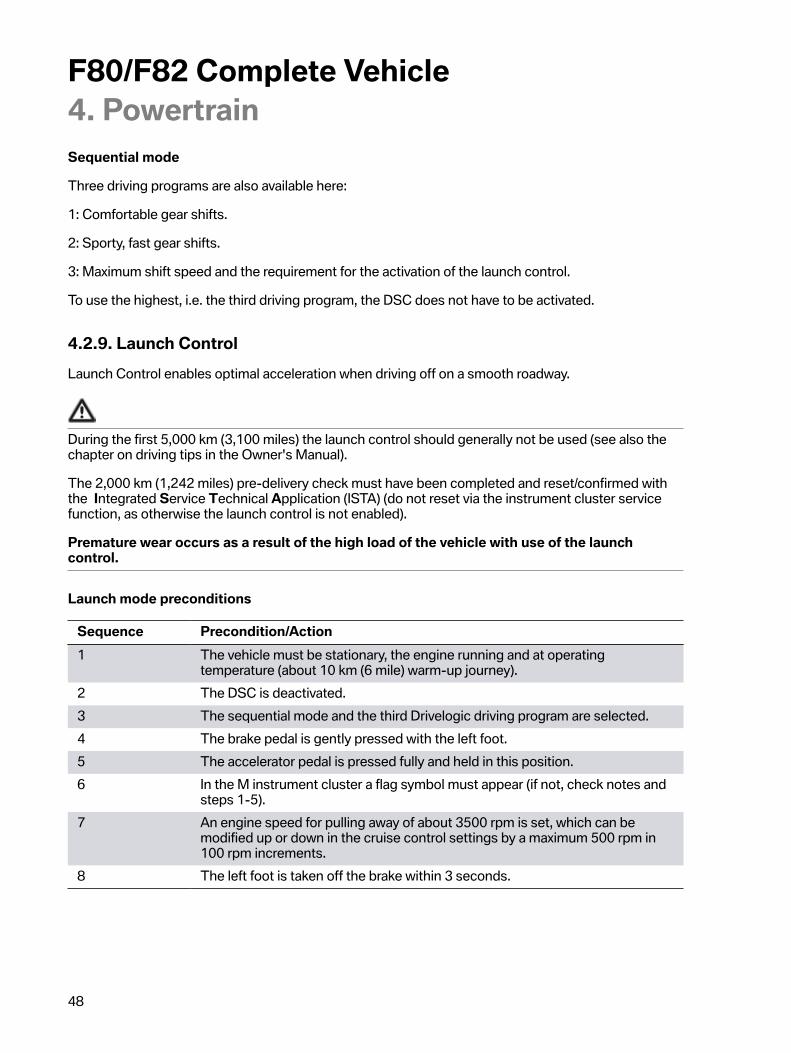
Sequential�mode
Three�driving�programs�are�also�available�here:
1:�Comfortable�gear�shifts.
2:�Sporty,�fast�gear�shifts.
3:�Maximum�shift�speed�and�the�requirement�for�the�activation�of�the�launch�control.
To�use�the�highest,�i.e.�the�third�driving�program,�the�DSC�does�not�have�to�be�activated.
4.2.9.�Launch�ControlLaunch�Control�enables�optimal�acceleration�when�driving�off�on�a�smooth�roadway.
During�the�first�5,000�km�(3,100�miles)�the�launch�control�should�generally�not�be�used�(see�also�thechapter�on�driving�tips�in�the�Owner's�Manual).
The�2,000�km�(1,242�miles)�pre-delivery�check�must�have�been�completed�and�reset/confirmed�withthe��Integrated�Service�Technical�Application�(ISTA)�(do�not�reset�via�the�instrument�cluster�servicefunction,�as�otherwise�the�launch�control�is�not�enabled).
Premature�wear�occurs�as�a�result�of�the�high�load�of�the�vehicle�with�use�of�the�launchcontrol.
Launch�mode�preconditions
Sequence Precondition/Action1 The�vehicle�must�be�stationary,�the�engine�running�and�at�operating
temperature�(about�10�km�(6�mile)�warm-up�journey).2 The�DSC�is�deactivated.3 The�sequential�mode�and�the�third�Drivelogic�driving�program�are�selected.4 The�brake�pedal�is�gently�pressed�with�the�left�foot.5 The�accelerator�pedal�is�pressed�fully�and�held�in�this�position.6 In�the�M�instrument�cluster�a�flag�symbol�must�appear�(if�not,�check�notes�and
steps�1-5).7 An�engine�speed�for�pulling�away�of�about�3500�rpm�is�set,�which�can�be
modified�up�or�down�in�the�cruise�control�settings�by�a�maximum�500�rpm�in100�rpm�increments.
8 The�left�foot�is�taken�off�the�brake�within�3�seconds.

F80/F82�Complete�Vehicle4.�Powertrain
49
Effect
• The�Launch�Control�shifts�up�to�5th�gear�independently�with�the�shortest�possible�shiftingtimes�and�enhanced�driving�performance�shift�points�as�long�as�the�driver�has�the�acceleratorpedal�pressed�in�fully�and�a�time�limit�of�22�seconds�is�not�exceeded�for�the�acceleration.
• The�start�flag�in�the�instrument�cluster�remains�active.
Automatic�deactivation
• The�driver�releases�(also�if�only�temporary)�the�accelerator�pedal�full�load�positionduring�acceleration�or�the�acceleration�phase�reaches�a�duration�of�22�seconds.
If�even�one�of�these�preconditions�is�not�met,�it�is�not�possible�to�activate�the�Launch�Control.
Also�at�excessive�transmission�oil�temperature�(e.g.�repeat�Launch�Control�or�race-like�start),activation�is�not�allowed�and�locked�until�an�acceptable�temperature�threshold�is�reached.
The�start�flag�goes�out�with�every�deactivation�and�the�automatic�forced�upshift�is�cancelled.
4.2.10.�Transmission�control�unitThe�M�DCT�control�unit�is�installed�in�the�mechatronics�module�in�the�transmission�similar�to�theGS7D36SG.
The�software�is�adapted�to�the�F80/F82.
4.2.11.�Emergency�gearbox�release
The�emergency�gearbox�release�is�deleted�similar�to�the�F10,�F12,�F13�and�F06.For�towing�away�please�observed�the�information�in�the�Owner's�Manual�of�the�vehicle.

F80/F82�Complete�Vehicle4.�Powertrain
50
4.2.12.�Service�information
Transmission�oil�circuit
When�work�is�required�on�the�oil�circuit�of�the�DCT�(regardless�if�it�is�the�M�DCT�or�AG�DCT),�forexample�after�an�accident,�or�if�the�oil�circuit�has�to�be�opened�due�to�a�repair,�there�must�be�maximumcleanliness.�This�includes:
• Thoroughly�cleaning�the�outer�oil�circuit�areas�before�disassembly�of�the�components�oropening�the�oil�circuit.
• All�openings�and�lines�must�be�closed�immediately�after�disassembly�with�clean�original�plugs.Do�not�use�unsealed�components�or�replacement�parts�of�the�oil�circuit�without�checking�forcleanliness.
• The�workbay�at�which�a�M�DCT�is�opened�must�be�extremely�clean�and�secured�against�dirtcontamination,�also�during�work�interruptions.�For�example�by�covering�with�a�clean�and�lint-free�cover.
Lifetime�oil�filling
Similar�to�the�E9x�M3�and�F1x�M5/M6�with�M�DCT�Drivelogic,�no�transmission�oil�change�is�currentlyplanned�at�2,000�km/�1200�miles�(pre-delivery�check)�or�every�third�engine�oil�change.
Repair/Part�exchange
Depending�on�the�type�of�repair,�the�data�status�of�the�M�DCT�must�be�read�out�beforehand�and�readin�again�after�the�component�has�been�replaced�(e.g.�replacement�of�mechatronics�module).
Depending�on�the�type�of�repair�(e.g.�dual�clutch�change),�the�"Neutral"�gear�selection�position�mustbe�selected�before�the�engine�is�stopped.
The�current�information�and�specifications�in�the�documents�in�the�Integrated�Service�TechnicalApplication�(ISTA)�must�be�observed�in�each�case.

F80/F82�Complete�Vehicle4.�Powertrain
51
4.3.�DriveshaftFor�the�first�time�a�one-piece�carbon�driveshaft�is�used�in�a�BMW�M�vehicle.�Traditionally�steel�oraluminum�driveshafts�are�required�for�a�vehicle�designed�for�high�performance.�In�order�to�be�ableto�transmit�the�torque�and�engine�speeds�they�are�designed�as�a�two-piece�component�and�havea�center�mount.�Only�this�design�ensures�high-speed�performance,�"critical�bending�speed".�Thetube�element�of�the�new�M3/M4�Coupe�carbon�driveshaft�enables�a�one-piece�design�due�to�itsspecific�material�properties.�High�rigidity�was�achieved�with�the�tubular�design�of�the�driveshaft�andthe�low�density�of�the�carbon�material�used�in�its�fabrication.�In�addition,�the�legally�mandated�safetyrequirements�were�able�to�be�integrated�in�the�design.
The�significant�weight�saving�along�with�excellent�rigidity�was�able�to�be�realized�by�using�low�materialdensity�of�carbon�and�eliminating�the�center�mount.
In�addition�other�desired�requirements,�such�as�corrosion�resistance,�low�length�compensation�andenhanced�comfort�(oscillation�acoustics)�can�be�satisfied�with�the�use�of�the�carbon�driveshaft.
In�comparison�to�the�predecessor�driveshaft�in�the�E9x�M3,�the�weight�was�able�to�be�reduced�by�5.3kg�to�7.6�kg.
F80/F82�carbon�driveshaft
Index Explanation1 Flexible�disc�joint2 Pipe�adapter,�front3 Support�ring4 Carbon�pipe5 Pipe�adapter,�rear6 Sliding�piece7 Flange,�rear�axle�differential

F80/F82�Complete�Vehicle4.�Powertrain
52
4.3.1.�Service�information
• During�disassembly�ensure�that�the�carbon�driveshaft�is�removed�first�at�the�rear�(at�the�slidingpiece)�and�then�at�the�front�carrier�(flexible�disc).�The�installation�should�be�done�in�the�reversesequence.
• In�the�sliding�piece�there�is�a�grease�filling,�which�is�coordinated�precisely�to�requirements�andis�required�for�the�function.�Therefore,�do�not�remove�the�grease�cap�before�the�driveshaftis�pushed�together�for�the�installation�at�the�sliding�piece.�Remove�the�grease�cap�after�thepushing�together�and�then�screw�the�driveshaft�at�the�rear�axle�differential.
• Please�check�the�U-type�bellows�again�after�pushing�together.�The�U-type�bellows�should�notarch�outwards,�bend�back�if�necessary.
The�carbon�driveshaft�is�highly�sensitive�to�impacts,�therefore�the�driveshaft�should�not�be�stored�in�anupright�position.�The�carbon�driveshaft�should�be�stored�in�a�horizontal�position�or�suspended.Also�during�this�storage�period�keep�the�carbon�driveshaft�away�from�impacts.
A�clear�indicator�protective�layer�(woven�fabric)�is�attached�to�the�carbon�driveshaft.�If�the�carbondriveshaft�was�subjected�to�an�impact,�small�cracks�in�the�form�of�a�spider�web�appear�on�this�layer.Damage�can�be�identified�by�means�of�this�crack�and�the�necessary�measures�deduced�from�adamage�pattern�catalog�in�the�Integrated�Service�Technical�Application�(ISTA).
The�current�information�and�specifications�in�the�documents�found�in�the�Integrated�Service�TechnicalApplication�(ISTA)�must�be�observed�in�each�case.
F80/F82�carbon�driveshaft,�indicator�layer
4.4.�Rear�axle�final�drive
4.4.1.�Active�M�DifferentialThis�electronically/electromechanically�controlled�rear�axle�differential�lock�was�developed�especiallyfor�the�F10�M5,�it�is�used�in�the�F06/F12/F13�M6�and�now�in�the�F80/F82.
F80/F82�Complete�Vehicle4.�Powertrain
53
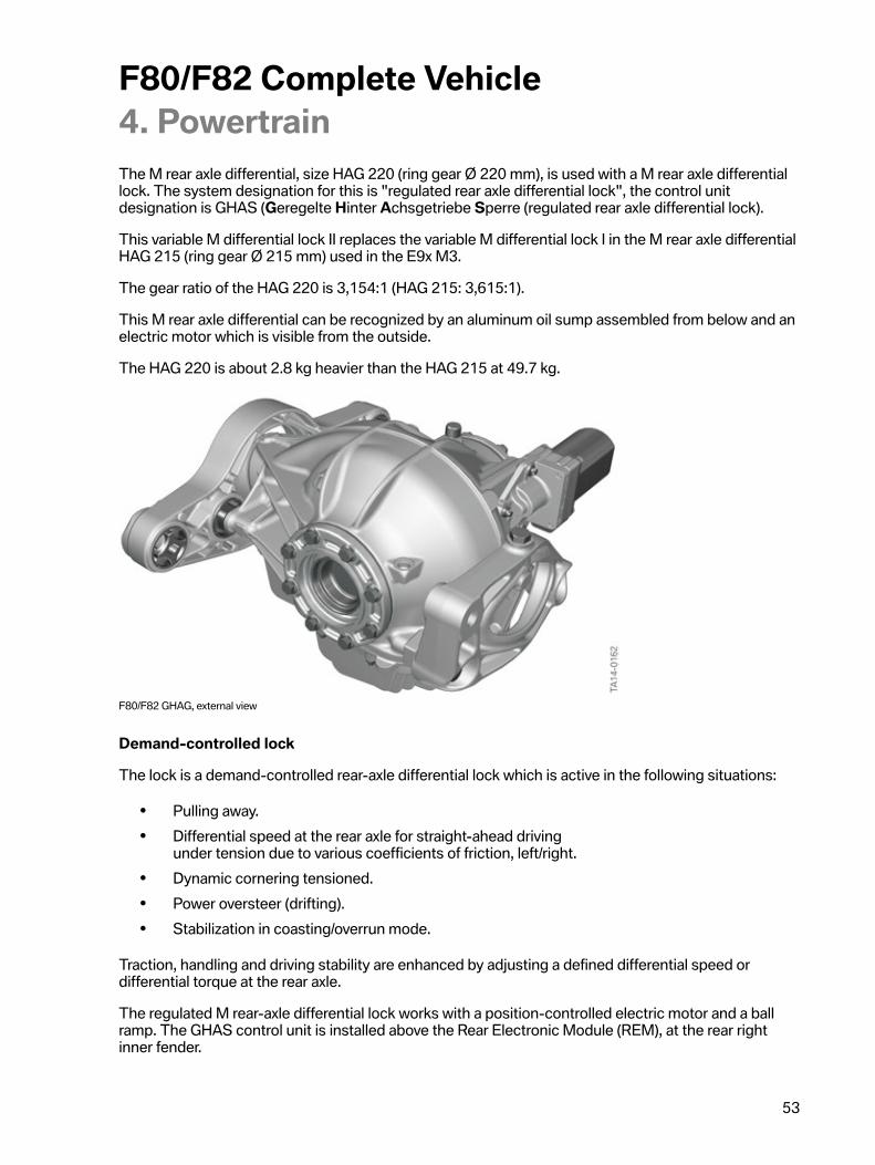
The�M�rear�axle�differential,�size�HAG�220�(ring�gear��220�mm),�is�used�with�a�M�rear�axle�differentiallock.�The�system�designation�for�this�is�"regulated�rear�axle�differential�lock",�the�control�unitdesignation�is�GHAS�(Geregelte�Hinter�Achsgetriebe�Sperre�(regulated�rear�axle�differential�lock).
This�variable�M�differential�lock�II�replaces�the�variable�M�differential�lock�I�in�the�M�rear�axle�differentialHAG�215�(ring�gear��215�mm)�used�in�the�E9x�M3.
The�gear�ratio�of�the�HAG�220�is�3,154:1�(HAG�215:�3,615:1).
This�M�rear�axle�differential�can�be�recognized�by�an�aluminum�oil�sump�assembled�from�below�and�anelectric�motor�which�is�visible�from�the�outside.
The�HAG�220�is�about�2.8�kg�heavier�than�the�HAG�215�at�49.7�kg.
F80/F82�GHAG,�external�view
Demand-controlled�lock
The�lock�is�a�demand-controlled�rear-axle�differential�lock�which�is�active�in�the�following�situations:
• Pulling�away.• Differential�speed�at�the�rear�axle�for�straight-ahead�driving
under�tension�due�to�various�coefficients�of�friction,�left/right.• Dynamic�cornering�tensioned.• Power�oversteer�(drifting).• Stabilization�in�coasting/overrun�mode.
Traction,�handling�and�driving�stability�are�enhanced�by�adjusting�a�defined�differential�speed�ordifferential�torque�at�the�rear�axle.
The�regulated�M�rear-axle�differential�lock�works�with�a�position-controlled�electric�motor�and�a�ballramp.�The�GHAS�control�unit�is�installed�above�the�Rear�Electronic�Module�(REM),�at�the�rear�rightinner�fender.

F80/F82�Complete�Vehicle4.�Powertrain
54
4.4.2.�Structure/FunctionThe�lock-up�torque�is�generated�by�a�multi-disc�clutch.�The�necessary�axial�pressure�is�applied�to�themulti-disc�clutch�by�the�position-controlled�direct�current�motor�by�means�of�gears�and�a�ball�rampmechanism.�The�clutch�package�operates�between�the�differential�housing�(steel�outer�discs)�and�theright�output�(molybdenum-coated�steel�inner�discs).
F80/F82�rear�axle�differential,�section�view
System�components:
• Wiring�harness• Regulated�differential�lock�control�unit�(GHAS)• Electric�motor�and�transmission�gearing• Lock

F80/F82�Complete�Vehicle4.�Powertrain
55
F80/F82�components�of�the�locking�differential:�Exploded�diagram
Index Explanation1 Electric�motor2 Intermediate�gear3 Ball�ramp�consisting�of�geared�mobile�adjusting�disc�and�first�half�of�ball�ramp4 Balls/Spherical�washers5 Fixed�pressure�disc�with�second�half�of�ball�ramp6 Axial�needle�bearing

F80/F82�Complete�Vehicle4.�Powertrain
56
Index Explanation7 Axial�bearing�thrust�washer8 Circlip�(ball�bearing�fixing)9 Ball�bearing�between�inner�output�hub�and�differential�housing10 Disc�spring�pressure�ring11 Diaphragm�spring12 Differential�lid�(connected�to�differential�housing,�cannot�rotate)13 Pressure�plate14 Disc�set15 Counter�pressure�plate
F80/F82�Locking�Differential,�section�view
Index Explanation1 Electric�motor2 Intermediate�gear3 Ball�ramp�consisting�of�geared�mobile�adjusting�disc�and�first�half�of�ball�ramp4 Balls/Spherical�washers5 Fixed�pressure�disc�with�second�half�of�ball�ramp

F80/F82�Complete�Vehicle4.�Powertrain
57
Index Explanation6 Axial�needle�bearing7 Axial�bearing�thrust�washer8 Circlip�(ball�bearing�fixing)9 Ball�bearing�between�inner�output�hub�and�differential�housing10 Disc�spring�pressure�ring11 Diaphragm�spring12 Differential�lid�(connected�to�differential�housing,�cannot�rotate)13 Pressure�plate14 Disc�set15 Counter�pressure�plate16 First�output�bevel�gear17 Second�output�bevel�gear18 Differential�housing�(connected�to�outer�discs)
The�electric�motor�(1)�is�bolted�on�to�the�housing�and�the�pressure�disc�fixed�to�the�second�ball�ramphalf�(5)�in�the�housing.�The�mobile�components�of�the�ball�ramp�(2,�3�and�4)�generate�the�necessaryaxial�displacement�of�the�pressure�disc�(5).�These�components�are�not�subject�to�the�differentialtransmission�rotation�and�are�disconnected�from�the�rotating�components�by�an�axial�needle�bearing(6).
The�components�with�the�index�6�to�18�belong�to�the�differential�and�rotate�proportional�to�the�rearaxle�gear�speeds.
The�locking�is�done�between�the�right�output�(16)�and�the�differential�housing�(18)�and�counteracts�adifference�in�speed�between�the�output�bevel�gears�(16�and�17).�The�disc�spring�(11)�opens�the�lockwhen�the�engine�is�not�supplied�with�current.
4.4.3.�System�informationThe�GHAS�control�unit�evaluates�the�dynamic�handling�characteristics�parameters�made�available�byother�control�units�via�the�FlexRay�data�bus�and�determines�the�lock-up�torque�to�be�applied.�The�DSCcontrol�unit�can�also�request�separate�and�higher-level�locking�interventions�to�stabilize�the�vehicleboth�when�the�DSC�is�activated�and�deactivated.
The�position-controlled�direct�current�motor�is�activated�directly�by�the�power�electronics�of�the�GHAScontrol�unit�with�vehicle�voltage�via�a�pulse-width-modulated�signal.�The�frequency�is�12.8�kHz�and�themaximum�current�level�is�30�A.
The�electric�motor�is�equipped�with�two�hall�effect�sensors�to�determine�its�position�and�the�directionof�rotation.

F80/F82�Complete�Vehicle4.�Powertrain
58
System�wiring�diagram
F80/F82�GHAS,�system�wiring�diagram

F80/F82�Complete�Vehicle4.�Powertrain
59
Index Explanation1 Dynamic�Stability�Control�(DSC)2 Digital�Motor�Electronics�(DME)3 Front�Electronic�Module�(FEM)4 Integrated�Chassis�Management�(ICM)5 Components�of�the�regulated�rear�axle�differential�lock6 Control�unit�of�the�regulated�rear�axle�differential�lock�(GHAS)7 Power�distribution�box,�rear
Interfaces
The�regulated�differential�lock�(GHS)�control�unit�works�with�the�following�control�units�and�includesthe�following�information:
Control�unit Bus�system InformationFEM -�Terminal�status
-�Vehicle�identification�number�(forencoding)-�Vehicle�condition�(power�managementand�fault�memory�block,�e.g.�in�the�eventof�voltage�drop�by�engine�start)
DME PT-CAN/FlexRay -�Accelerator�pedal�angle-�Wheel�drive�torque-�"Engine�running"�signal
DSC FlexRay -�Wheel�speed-�Setpoint�axial�torque�distribution-�Stabilization�status-�Brake�value
ICM FlexRay -�Tolerance�adjustment�of�wheel(adjustment�of�different�wheelcircumferences)-�Lateral�acceleration-�Yaw�rate-�Driving�speed-�Road�longitudinal�tilt-�Steering�angle
FEM-ZGM Gateway�for�all�bus�systems Forwarding�of�information�to�regulateddifferential�lock
Electric�motor�location�determination
To�determine�the�position�of�the�electric�motor�two�hall�effect�sensors�in�the�motor�are�evaluated.
To�determine�the�characteristic�curve�of�the�lock-up�torque�via�the�motor�position�a�re-calibration�isregularly�performed�to�compensate�for�the�wear�in�the�clutch.

F80/F82�Complete�Vehicle4.�Powertrain
60
In�order�to�be�able�to�assign�a�corresponding�clutch�lock-up�torque�to�a�certain�position�of�theservomotor,�and�to�take�wear�influences�into�consideration,�every�1000�km�(621�miles)�or�afteran�energy�input�in�the�lock�of�100�kJ�(corresponds�to�a�lap�of�the�Nürburgring)�a�reference�run�isperformed�after�the�engine�is�shut�down.�During�this�reference�run�the�motor�is�subjected�to�a�definedcurrent�level.�The�lock-up�torque�1500�Nm�(1106�lb-ft)�is�assigned�to�the�resulting�position.
Temperature�monitoring
Three�temperature�sensors�are�installed.�The�temperature�of�the�control�unit�(driver�output�stage),the�temperature�of�the�electric�motor�and�the�transmission�oil�temperature�are�monitored.
The�temperature�thresholds�are�as�follows:Control�unit�105�°C�(221�°F)Electric�motor�160�°C�(320�°F)Oil�temperature�190�°C�(374�°F)
The�current�oil�specification�is�"BMW�final�drive�oil�synthetic�MSP/A"�(for�e.g.�Castrol�SAF-XJ)�and�isthe�same�oil�used�in�the�previous�M�vehicles�with�variable�M�differential�lock.
The�capacity�is�currently�1.2�l�(1.27�qrt).�The�current�specification�in�our�service�information"Operating�materials"�and�the�technical�data�in�the�Integrated�Service�Technical�Application�(ISTA)must�be�observed�in�each�case.
If,�due�to�a�fault,�the�GHAS�lock�function�is�switched�off�or�fails,�a�locked�differential�is�automaticallyreopened�as�the�lock�function�is�not�self-locking.�The�driver�is�warned�and�informed�regarding�theeffects�that�can�be�expected:
1.�Loss�of�traction�with�dynamic�driving�style�and�low�coefficients�of�friction,�particularly�with�differentcoefficients�of�friction,�left/right.
2.�Possible�deterioration�of�stability�in�dynamic�driving�situations.
4.4.4.�Service�information
• For�a�replacement�of�the�GHAS�control�unit�an�encoding�(activation�of�vehicle-relatedcharacteristic�curve)�and�then�an�initial�calibration�are�necessary�and�then�the�fault�memorymust�be�deleted.
• After�the�replacement�of�the�entire�M�rear�axle�differential�a�calibration�must�be�performed�andthen�the�fault�memory�must�be�deleted.
• For�a�replacement�of�the�electric�motor,�electric�motor�plus�intermediate�gear�or�oiltemperature�sensor,�only�the�fault�memory�must�be�deleted.
The�final�drive�oil�is�currently�replaced�every�2000�km/1200�miles�(pre-delivery�check)�and�at�everythird�engine�oil�change.
The�current�information�and�specifications�in�the�Integrated�Service�Technical�Application�(ISTA)�mustbe�observed.

F80/F82�Complete�Vehicle4.�Powertrain
61
4.4.5.�Half-shaftsAs�is�typical�for�BMW�M�vehicles,�the�output�shafts�have�a�hollow�design�in�order�to�make�optimal�useof�the�material�in�relation�to�material�usage,�weight�and�rigidity.
These�lightweight�half-shafts�are�designed�to�transmit�up�to�7000�Nm�(5163�lb-ft)�torque.
The�CV�joints�and�the�trunnion�mounts�of�the�F80/F82�are�drilled�hollow.�This�is�the�first�time�thisintelligent�lightweight�construction�was�implemented�in�a�M�vehicle.
F80/F82�output�shaft
Index Explanation1 CV�Joint�drilled�hollow�on�the�wheel-side�with�trunnion�mount2 Boot3 Hollow�shaft4 CV�Joint�drilled�hollow�at�the�rear�axle�differential�with�trunnion�mount
The�special�feature�of�the�output�shafts�is�the�double-sided�gearing.�They�are�no�longer�flange-mounted�at�the�rear�axle�differential�and�inserted�in�the�wheel�hub,�but�are�inserted�in�the�rear�axledifferential�and�in�the�drive�flange.�The�procedure�has�thus�changed�for�installation�and�removal.
The�current�information�and�specifications�in�the�Integrated�Service�Technical�Application�must�beobserved.
4.4.6.�Wheel�flangeThe�intelligent�lightweight�construction�was�also�implemented�with�regard�to�the�wheel�flanges�of�F80/F82.

F80/F82�Complete�Vehicle4.�Powertrain
62
The�wheel�flange�at�the�front�axle�and�the�rear�axle�have�been�enhanced�in�relation�to�their�weight.The�material�has�been�reduced�at�places�subject�to�little�stress,�and�accumulated�at�heavily�stressedplaces.
With�these�measures�provide�a�weight�saving�of�about�1.13�kg�(2.5�lbs)�in�comparison�to�the�E9x�M3.
F80/F82�wheel�flange
Index ExplanationA Wheel�bearing�unit�with�front�wheel�flangeB Drive�flange,�rear

F80/F82�Complete�Vehicle5.�Chassis�and�Suspension
63
F80/F82�chassis�and�suspension,�complete
The�chassis�and�suspension�is�based�on�the�technology�of�the�F3x�and�the�E9x�M3,�whereby�almostall�components�are�again�new�and�specific�to�M�or�have�been�adapted.
Designation Unit E9x�M3 F10�M5 F80/F82–M3/M4Coupe
Wheelbase/turning�circle [mm/m] 2761/11,7 2964/12,4 2812/12,2Front�track�width [mm] 1540 1627 1579Rear�track�width [mm] 1539 1582 1603Front�Axle M�two-joint
spring-strutfront�axle
M�double-wishbone�axle
M�two-jointspring-strutfront�axle
Steering Hydraulic�Mrack-and-pinionsteering�withM�Servotronic
Hydraulic�Mrack-and-pinionsteering�withM�Servotronic
Electricalrack-and-pinion
steering�(EPS)with�M
ServotronicAverage�overall�ratio 12.5 13,05 15Steering�wheel�turnsEnd�stop-end�stop
2,4 2,6 2,5
Rear�axle M�5–jointrear�axle
M�IntegralIV�(based�onE60�M5)
M�5–jointrear�axle
Axle�ratio 3.154 3.154 3.462

F80/F82�Complete�Vehicle5.�Chassis�and�Suspension
64
5.1.�Front�AxleThe�front�axle�is�based�on�the�M�two-joint�spring�strut�front�axle�of�the�E9x�M3.�All�components�or�thebearings�are�new�to�M�or�have�been�adapted�and�the�M�front�axle�support�has�been�reinforced�with�astiffening�plate,�typical�of�M.
F80/F82�two-joint�spring�strut�front�axle
Index Explanation1 M�front�axle�support2 M�anti-roll�bar�link3 M�spring�strut�with�support�bearing4 M�swivel�bearing5 M�wheel�bearing�unit�with�wheel�flange6 M�track�rod

F80/F82�Complete�Vehicle5.�Chassis�and�Suspension
65
Index Explanation7 M�wishbone8 M�trailing�link�with�hydro�mount9 M�anti-roll�bar10 M�Servotronic�(EPS)11 M�stiffening�plate
All�components�have�been�redesigned�for�the�increased�requirements.�The�guiding�of�the�wheel�forcompression�and�steering�is�done�via�the�wishbone,�the�tension�strut,�the�spring�strut�and�the�trackrod.
In�order�to�guarantee�precise�wheel�guiding�in�transverse�direction�of�vehicle,�the�power�is�transmittedfrom�the�swivel�bearing�to�the�front�axle�guide�via�the�ball�joints�with�no�play.�In�order�to�also�guaranteethis�in�a�longitudinal�direction,�the�chassis�and�suspension�forces�are�transmitted�via�speciallydeveloped�elastomer�bearings�for�the�F80/F82�via�the�tension�struts�to�the�front�axle�support.
The�stiffening�plate�and�the�additional�screw�connections�of�the�axle�support�and�the�side�sills�alsoensure�an�increase�in�the�transverse�rigidity�of�the�front�of�the�vehicle�by�about�30%.
The�connection�between�the�spring�strut�and�the�swivel�bearing�was�realized�by�a�clamp�connectionsimilar�to�the�E82�M�and�E9x�M3.

F80/F82�Complete�Vehicle5.�Chassis�and�Suspension
66
F80/F82�spring�strut-swivel�bearing�connection
Index Explanation1 M�spring2 M�spring�strut3 M�anti-roll�bar�link4 M�swivel�bearing5 M�wheel�bearing�unit�with�wheel�flange6 M�wishbone7 M�tension�strut8 M�anti-roll�bar9 M�front�axle�support
The�intelligent�lightweight�construction�of�the�F80/F82�also�was�implemented�in�the�front�axleconcept.�The�wishbone,�wheel�carrier,�axle�support�and�the�stiffening�plate�are�manufactured�inlightweight�aluminum.

F80/F82�Complete�Vehicle5.�Chassis�and�Suspension
67
A�weight�saving�of�about�5�kg�was�achieved�with�these�measures�in�comparison�to�the�F3x�M3.
Further�weight�savings�were�achieved�with�the�design�of�the�spring�strut�in�aluminum,�as�well�as�thetubular�design�of�the�anti-roll�bar�(as�in�the�E9x�M3).
The�design�of�the�front�axle�was�done�in�close�cooperation�with�the�tires�which�were�also�speciallydeveloped�for�the�F80/F82.
5.1.1.�SteeringEfficientDynamics�measures�where�also�implemented�on�the�new�F80/F82.�The�rack-and-pinionsteering�has�electrical�steering�wheel�support�"M�Servotronic�based�on�EPS".
For�power�steering�assistance�is�done�via�an�electric�motor�located�parallel�to�the�steering�rackhousing.�The�power�transmission�is�done�via�a�ball�screw�design.
The�use�of�a�M�Servotronic�(EPS)�in�the�new�M3/M4�Coupe�results�in�a�weight�saving�of�about�3.5�kgin�comparison�to�the�hydraulic�steering�system�in�the�E9x�M3.
F80/F82�steering
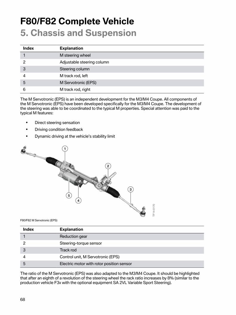
F80/F82�Complete�Vehicle5.�Chassis�and�Suspension
68
Index Explanation1 M�steering�wheel2 Adjustable�steering�column3 Steering�column4 M�track�rod,�left5 M�Servotronic�(EPS)6 M�track�rod,�right
The�M�Servotronic�(EPS)�is�an�independent�development�for�the�M3/M4�Coupe.�All�components�ofthe�M�Servotronic�(EPS)�have�been�developed�specifically�for�the�M3/M4�Coupe.�The�development�ofthe�steering�was�able�to�be�coordinated�to�the�typical�M�properties.�Special�attention�was�paid�to�thetypical�M�features:
• Direct�steering�sensation• Driving�condition�feedback• Dynamic�driving�at�the�vehicle’s�stability�limit
F80/F82�M�Servotronic�(EPS)
Index Explanation1 Reduction�gear2 Steering-torque�sensor3 Track�rod4 Control�unit,�M�Servotronic�(EPS)5 Electric�motor�with�rotor�position�sensor
The�ratio�of�the�M�Servotronic�(EPS)�was�also�adapted�to�the�M3/M4�Coupe.�It�should�be�highlightedthat�after�an�eighth�of�a�revolution�of�the�steering�wheel�the�rack�ratio�increases�by�8%�(similar�to�theproduction�vehicle�F3x�with�the�optional�equipment�SA�2VL�Variable�Sport�Steering).

F80/F82�Complete�Vehicle5.�Chassis�and�Suspension
69
Comparison�between�steering�gear�ratio�of�basic�M�Servotronic�(EPS)�steering�and�Variable�Sport�Steering�for�F80/F82
Index Explanation1 Rack�in�basic�version�of�F3x�(constant�gear�geometry)2 Variable�sport�steering�rack�(variable�gear�geometry)A More�indirect�steering�gear�ratio�(variable�sport�steering)B More�direct�steering�gear�ratio�(variable�sport�steering)X Steering�angley Rack�stroke
With�the�use�of�the�M�Servotronic�(EPS)�in�the�new�M3/M4�Coupe�the�parking�assistance�system"Parking�Maneuvering�Assistant"�(SA�5DP)�is�now�also�offered.
5.1.2.�ServotronicThe�Servotronic�function�known�from�traditional�hydraulic�steering�systems�is�also�used�in�the�MServotronic�(EPS)�and�is�installed�in�the�M3/M4�Coupe�as�standard.�It�is�a�M�Servotronic,�whichfunctions�according�to�the�same�operating�principle�as�in�production�vehicles.�The�difference�in�theM�Servotronic�is�that�three�stages�can�be�selected�in�comparison�to�two�stages�in�the�productionvehicles,�and�it�has�a�separate�button�in�the�driving�dynamics�button�panel�in�the�center�console.The�button�or�the�configuration�in�the�MDrive�menu�is�used�to�switch�between�"Comfort",�"Sport"�and"Sport+".�Here�the�corresponding�characteristic�curve�is�activated�and�in�Sport�direction�the�powersteering�support�is�also�noticeably�withdrawn.�The�program�selection�can�also�be�pre-configured�in�theMDrive�menu�and�selected�via�the�M�button�on�the�steering�wheel�assigned�to�the�MDrive.
F80/F82�Complete�Vehicle5.�Chassis�and�Suspension
70
5.1.3.�Steering�angle�sensorThe�information�on�the�steering�angle�is�not�recorded�by�the�Electronic�Power�Steering�(EPS)�and�notvia�a�separate�sensor�on�the�steering�wheel,�instead�its�calculated�based�on�the�motor�position�angleof�the�EPS�motor�in�relation�to�the�steering�wheel.
The�EPS�transmits�the�position�of�the�rack�to�the�ICM�control�unit�via�FlexRay.�During�this�process,the�EPS�calculates�the�absolute�position�of�the�rack�based�on�the�current�motor�position�of�the�EPSmotor�and�the�number�of�complete�revolutions�performed�by�the�motor�starting�from�the�zero�position(straight-ahead�driving�position).
Taking�this�position�as�the�starting�point,�the�ICM�control�unit�determines�the�wheel-specific�steeringangle�among�other�things�using�the�stored�ratio�parameters�(rack�to�wheel-specific�steering�angle)�andtransmits�this�via�FlexRay.�This�wheel-specific�steering�angle�is�used�by�the�DSC�among�other�thingsas�a�reference�variable�for�internal�control�functions.
In�cases�where�the�absolute�value�is�not�available�from�the�EPS�(loss�of�Terminal�30,�flash�process),the�absolute�value�is�determined�through�interaction�between�the�ICM�and�EPS�using�an�adaptationfunction�in�which�the�steering�wheel�is�turned�from�end�stop�to�end�stop�(e.g.�straight-ahead�position�->�left�->�right�->�straight-ahead�position).

F80/F82�Complete�Vehicle5.�Chassis�and�Suspension
71
5.1.4.�System�wiring�diagram,�M�Servotronic�(EPS)
F80/F82�system�wiring�diagram,�EPS

F80/F82�Complete�Vehicle5.�Chassis�and�Suspension
72
Index Explanation1 Dynamic�Stability�Control�(DSC)2 Digital�Motor�Electronics�(DME)3 M�Servotronic�(EPS)4 Power�distribution�box,�front5 Power�distribution�box,�engine�compartment6 Front�Electronic�Module�(FEM)7 Integrated�Chassis�Management�(ICM)8 Steering�column�switch�cluster�(SZL)9 Instrument�panel�(KOMBI)Terminal�15N Ignition�(after-run)Terminal�30 Terminal�30
5.2.�Rear�axleThe�M�rear�axle�is�based�on�the�five-link�rear�axle�from�E9x�M3.�All�components�and�bearings�wereredesigned�for�the�increased�requirements.
F80/F82�five-link�rear�axle
Index Explanation1 M�wheel�bearing�unit�with�drive�flange2 M�control�arm3 M�trailing�arm4 M�wishbone

F80/F82�Complete�Vehicle5.�Chassis�and�Suspension
73
Index Explanation5 M�rear�axle�support6 M�camber�control�arm7 M�track�control�arm8 M�hub�carrier
All�trailing�arms�and�also�the�wheel�carrier�are�manufactured�in�aluminum�forging�technology.This�design�reduces�the�unsprung�masses�of�the�wheel-controlling�components�in�comparison�to�theE9x�M3�by�about�3�kg�(6.6�lbs).
F80/F82�five-link�arrangement�with�wheel�carrier
Index Explanation1 M�wheel�bearing�unit�with�drive�flange2 M�hub�carrier3 M�control�arm4 M�track�control�arm5 M�wishbone6 M�rear�axle�support7 M�camber�control�arm8 M�trailing�arm
The�rear�axle�support�itself�is�made�from�steel�tubing�which�is�similar�to�a�steel�tube�grid�frame.

F80/F82�Complete�Vehicle5.�Chassis�and�Suspension
74
This�design�is�characterized�by�maximum�rigidity�and�minimal�weight.�The�M�rear�axle�support�is�fixedto�the�body�without�a�bearing.�This�fixed�connection�(bolted)�directly�to�the�body�ensures�an�optimizedwheel�guiding�and�thus�enhanced�directional�stability.�In�addition,�through�the�use�of�diagonal�strutsa�direct�transmission�of�the�longitudinal�forces�applied�during�braking�to�the�body�structure�wasachieved.
F80/F82�rear�axle�support
Index Explanation1 Attachment�point,�rear�axle�at�body�(fixed�(bolted)
connection�without�rubber�mount)2 Attachment�point�for�rear�axle�differential�(GHAG)3 M�rear�axle�support
Further�weight�savings�compared�to�the�F3x�M3�was�achieved�with�the�design�of�the�spring�strut�inaluminum,�as�well�as�the�tubular�design�of�the�anti-roll�bar�like�in�the�E9x�M3.
The�design�of�the�rear�axle�was�done�in�close�cooperation�with�the�tires�which�were�also�speciallydeveloped�for�the�F80/F82.

F80/F82�Complete�Vehicle5.�Chassis�and�Suspension
75
5.3.�Brakes�and�wheels/tires
5.3.1.�Brakes
M�Compound�brake
F80/F82�brake�system
Index Explanation1 Dynamic�Stability�Control�(DSC)2 Brake�fluid�expansion�tank3 Brake�servo�(left-hand�drive�vehicle)4 Parking�brake�lever5 Rear�brake�disc6 Rear�double-piston�fixed�caliper7 Brake�pedal8 Clutch�pedal9 Front�four-piston�fixed�caliper

F80/F82�Complete�Vehicle5.�Chassis�and�Suspension
76
Designation Unit E9x�M3 F10�M5 F80/F82–M3/M4�Coupe
Front�brake 1�piston,floating�caliper
6�pistons,fixed�caliper
4�pistons,fixed�caliper
Brake�disc,�front [mm] 360�x�30 400�x�36 380�x�30Rear�brakes 1�piston,
floating�caliper1�piston,
floating�caliper2�pistons,fixed�caliper
Brake�disc,�rear [mm] 350�x�24 396�x�24 370�x�24Parking�brake mechanical electro-
mechanicalmechanical
The�front�brakes�are�specific�to�the�F80/F82.�Large�perforated�M�compound�brake�discs�combinedwith�a�four-piston�fixed�calipers�are�used.�The�diameter�of�the�brake�disc�is�20�mm�larger�than�that�ofthe�E9x�M3.�All�brake�calipers�will�be�blue�with�a�color�M�logo�irrespective�of�the�external�vehicle�colorchosen.
F80/F82�front�brake
The�rear�brakes�are�specific�to�F80/F82.�The�diameter�of�the�rear�perforated�M�compound�brake�discsis�20�mm�larger�than�that�of�the�E9x�M3.�The�rear�brake�calipers�are�double-piston�fixed�type.

F80/F82�Complete�Vehicle5.�Chassis�and�Suspension
77
M�Carbon�ceramic�brake
The�M�Carbon�ceramic�brakes�are�available�as�optional�equipment�from�the�series�launch�of�the�newF80/F82.�In�addition�to�the�F10�M5,�the �F12�M6,�F13�M6�and�the�F06�M6.
The�M�Carbon�ceramic�brake�system�is�also�called�C/SiC�brake�system.
Depending�on�the�situation,�this�offers�a�further�increase�in�active�safety�compared�to�theM�Compound�brakes.�In�a�direct�comparison�it�also�offers�the�following:
• Even�more�direct/spontaneous�use�of�brake�force• Maximum�heat�resistance�even�with�continuous�sporty�operation• Higher�fading�stability• Significantly�reduced�wear• 7�kg�(15.4�lbs)�weight�reduction�of�rotating�wheel�masses• Increased�suitability�for�winter�driving�conditions�thanks�to�corrosion�resistance.
F80/F82�M�Carbon�ceramic�brake,�front�axle
As�a�visible�distinguishing�feature�to�the�M�Carbon�ceramic�brake�system�uses�gold�painted�brakecalipers�with�a�color�M�logo.
The�F80/F82�Carbon�ceramic�brake�system�can�only�be�used�with�the�19"�M�wheel�rim�due�to�thelarger�brake�discs�at�the�front.
The�brake�discs�are�manufactured�by�Brembo�SGL�Carbon�Ceramic�Brakes�GmbH.

F80/F82�Complete�Vehicle5.�Chassis�and�Suspension
78
Designation Unit F10�M5 F80/F82–M3/M4�Coupe
Front�brake 6�pistons,fixed�caliper
6�pistons,fixed�caliper
Brake�disc,�front [mm] 410�x�38 400�x�38Rear�brakes 1�piston,
floating�caliper4�pistons,fixed�caliper
Brake�disc [mm] 396�x�26 380�x�28Parking�brake electro-
mechanicalmechanical
Further�information�on�the�M�Carbon�ceramic�brake�can�be�found�in�the�"�ST1216�M�Carbon�CeramicBrakes"�training�material�available�in�TIS�and�ICP.
For�necessary�service�work�the�current�information�and�specifications�in�the�documents�in�theIntegrated�Service�Technical�Application�(ISTA)�must�be�observed�in�each�case.
Dynamic�Stability�Control�(DSC)
The�MK�100�from�Continental�is�used�as�a�Dynamic�Stability�Control�(DSC)�system.�The�characteristicmaps�of�the�DSC�are�M-specific�and�adapted�to�the�respective�brake�system�M�Compound�or�MCarbon�ceramic�brake.
Modification�to�brake�pad�wear�monitoring
Similar�to�the�E82�M�Coupe�and�the�F10�M5,�the�F80/F82�only�has�one�brake�pad�wear�sensor�on�theleft�at�the�front�axle.�The�second�is�at�the�rear�axle�on�the�right.

F80/F82�Complete�Vehicle5.�Chassis�and�Suspension
79
5.3.2.�Wheels/tires
Summer�equipment
F80/F82�summer�wheels
Index ExplanationA 18"�513M�standard�wheelB 19"�437M�wheel,�optional�equipment�in�two�color�variants
The�following�wheel/tire�combinations�are�offered:
Standard�equipment
Designation E9x�M3 F10�M5 F80/F82–M3/M4�Coupe
LM�EH2+�wheel�rim,�standard�wheel,front�(forged)
8.5�x�18�IS�29 9J�x�19�IS�32�mm 9J�x�18�IS�29Styling�513M
LM�EH2+�wheel�rim,�standard�wheel,rear�(forge)
9.5�x�18�IS�23 10J�x�19IS�34�mm
10J�x�18�IS�40Styling�513M
Standard�tires,�front�(Michelin�PilotSuper�Sport)
245/40�ZR�18 265/40�ZR�19 255/40�ZR�18
Standard�tires,�rear�(Michelin�PilotSuper�Sport)
265/40�ZR�18 295/35�ZR�19 275/40�ZR�18
Optional�equipment
Designation F80/F82–M3/M4�CoupeLM�EH2�wheel�rim,�front�(forged)�styling�437M 9J�x�19�IS�29LM�EH2�wheel�rim,�rear�(forged)�styling�437M 10J�x�19�IS�40Tires,�front�(Michelin�Pilot�Super�Sport) 255/35�ZR�19Tires,�rear�(Michelin�Pilot�Super�Sport) 275/35�ZR�19
The�components�of�the�above-listed�wheel/tire�combinations�have�been�developed�especially�for�theF80/F82.�This�can�be�recognized�by�the�star�on�the�outer�side�of�the�tire,�among�other�things.

F80/F82�Complete�Vehicle5.�Chassis�and�Suspension
80
Other�combinations�may�have�a�negative�effect�on�the�performance�and�the�drivability�of�the�F80/F82and�lead�to�forfeiture�of�the�operating�licence�with�forfeiture�of�the�insurance�coverage.
5.4.�Dynamic�handling�control�systemsThe�M-specific�coordination�of�the�driving�dynamics�(longitudinal,�transverse�and�vertical)�was�done�onthe�Nürburgring�Nordschleife.�The�main�criteria�were�handling�and�the�lap�times.
5.4.1.�Vertical�Dynamics�ManagementFor�vehicles�with�a�M�sports�suspension�(SA�2VF)�the�Electronic�Damper�Control�(EDC)�is�installed.Here�four�continuously�adjustable�shock�absorbers�with�coupled�rebound/compression�stageadjustment�produce�damping�forces�according�to�requirements.
Through�the�use�of�forged�aluminum�dampers,�the�weight�of�the�M�sports�suspension�in�the�M3/M4�Coupe�was�able�to�be�reduced�by�about�5.5�kg�when�compared�to�the�adaptive�chassis�andsuspension�in�the�F3x�M3.�Therefore�the�M�sports�suspension�also�contributes�to�the�consistentlightweight�construction�concept�of�the�new�M3/M4�Coupe.
The�EDC�function�integrated�in�the�M�Vertical�Dynamics�Management�control�unit�(M�VDM)�controlsthe�adjustable�dampers.
The�vehicle’s�drivability�can�be�influenced�with�regards�to�driving�dynamics�via�the�M�sportssuspension�(EDC)�button�in�the�driving�dynamics�button�panel�at�the�center�console.�The�programselection�can�also�be�pre-configured�in�the�MDrive�menu�and�selected�via�the�corresponding�M�buttonon�the�steering�wheel.

F80/F82�Complete�Vehicle5.�Chassis�and�Suspension
81
System�overview
F80/F82�system�overview�of�EDC
Index Explanation1 Electronic�adjustable�damper,�rear2 VDM�control�unit3 Wheel�acceleration�sensor,�front4 EDC�button5 Electronic�adjustable�damper,�front6 Wheel�acceleration�sensor,�rear

F80/F82�Complete�Vehicle5.�Chassis�and�Suspension
82
System�wiring�diagram
F80/F82�system�wiring�diagram�of�EDC

F80/F82�Complete�Vehicle5.�Chassis�and�Suspension
83
Index Explanation1 Vertical�wheel�acceleration�sensor,�front�left2 Electromagnetic�adjusting�valve,�front�left3 Dynamic�Stability�Control�(DSC)4 Electromagnetic�adjusting�valve,�front�right5 Vertical�wheel�acceleration�sensor,�front�right6 Power�distribution�box,�luggage�compartment7 Vertical�wheel�acceleration�sensor,�rear�right8 Electromagnetic�adjusting�valve,�rear�right9 Electromagnetic�adjusting�valve,�rear�left10 Vertical�wheel�acceleration�sensor,�rear�left11 Vertical�Dynamics�Management�(VDM)12 Integrated�Chassis�Management�(ICM)13 EDC�button14 Front�Electronic�Module�(FEM)Terminal�30 Terminal�30Terminal�15N Ignition�(after-run)
System�function
The�Electronic�Damper�Control�(EDC)�is�a�variable,�electronically�controlled�shock�absorberadjustment�system�that�controls�the�vertical�dynamics�of�the�vehicle.�The�front�axle�damper�and�rearaxle�damper�can�be�controlled�independent�of�each�other.�The�EDC�adapts�the�damping�forces�of�theshock�absorber�more�or�less�instantly�to�the�changing�road�or�driving�conditions.
The�Electronic�Damper�Control�(EDC)�is�installed�with�the�optional�equipment�SA�2VF�"M�sportssuspension".
The�EDC�consists�of:
• four�continuously�adjustable�shock�absorbers�with�coupled�rebound/compression�stageadjustment
• the�VDM�control�unit• two�wheel�acceleration�sensors�on�the�front�axle�to�determine�the�wheel�movement• two�wheel�acceleration�sensors�on�the�rear�axle�to�determine�the�wheel�movement• a�sensor�cluster�integrated�into�the�ICM�control�unit�which�determines�the�body
movements�(pitch,�vertical,�roll).

F80/F82�Complete�Vehicle5.�Chassis�and�Suspension
84
The�sensors�in�the�vehicle�permanently�measure:
• the�body�and�wheel�acceleration• the�current�lateral�and�longitudinal�acceleration• the�vehicle�speed• the�steering�wheel�position
Based�on�this�measured�data,�the�VDM�control�unit�calculates�the�control�commands�to�be�sent�tothe�electromagnetic�valves�in�the�shock�absorbers�for�each�individual�wheel�according�to�the�roadprofile�and�driving�situation.�This�means�that�the�damping�forces�will�always�be�applied�according�tothe�requirements.
This�improves�ride�comfort�and�also�increases�driving�dynamics.
This�improves�the�vehicle's:
• Suitability�for�long-distance�journeys• Enhanced�body�stability�and�agility• Improves�driving�safety�by�minimizing�wheel�load
fluctuations�and�reducing�the�stopping�distance.
M�sports�suspension�(EDC)�button�option
The�button�obtains�its�ground�from�the�ICM�and�sends�back�a�ground�signal�upon�actuation�to�theICM.�The�ICM�forwards�this�information�on�the�FlexRay�data�bus�to�the�M�VDM.
In�the�F80/F82�Electronic�Damper�Control�there�are�options�"Comfort",�"Sport"�and�"Sport+".All�three�programs�have�dynamic�control�in�the�F80/F82.
Note:
In�the�first�E92/E90�M3�models�the�EDC�had�the�three�options,�"Comfort",�"Normal"�and�"Sport",whereby�with�the�"Sport"�option�there�is�no�dynamic�control,�but�the�dampers�are�set�very�hard.�Thisis�primarily�suited�for�a�cone�slalom�on�an�even�surface.�However,�the�fastest�possible�times�on�normalroads�cannot�be�achieved�with�the�"Sport"�option.�The�E93�M3�was�dynamically�controlled�fromstandard�production�in�"Sport"�mode,�as�well�as�in�all�subsequent�models�in�the�F10�M5,�F12/F13�M6and�the�F06�M6�in�"Sport+"�mode.
Program�description
• "Comfort"�emphasizes�the�comfortable�design�in�the�F80/F82�in�order�to�satisfy�the�comfortrequirements�of�a�M3/M4�Coupe�customer.�The�damper�hardness�is�set�to�comfortable.
• "Sport"�supports�a�dynamic�and�sporty�driving�style�with�increased�damper�hardness.• "Sport+"�in�the�F80/F82�means�that�dynamic�control�now�also�takes�place�here,�whereby�the
damper�hardness�is�increased�further�in�comparison�to�"Normal".�It�may�therefore�also�be�thebest�selection�for�the�fastest�times�on�different�route�profiles�on�very�even�surfaces,�unlike�aroute�profile�similar�to�a�"cone-lined�slalom".

F80/F82�Complete�Vehicle5.�Chassis�and�Suspension
85
5.4.2.�Transverse�dynamics�management
Integrated�Chassis�Management
The�ICM�is�the�transverse�dynamics�system�network.�This�control�unit�coordinates�the�interactionbetween�the�M�Servotronic�(EPS),�DSC,�M�sports�suspension,�engine�control,�M�DCT�and�theregulated�rear�axle�differential�lock�(GHAS).
5.4.3.�Longitudinal�dynamics�managementThe�LDM�is�performed�by�the�DSC.�The�DSC�MK�100�from�Continental�is�used�in�the�F80/F82.
M�dynamic�mode�and�DSC�OFF�mode
In�M�dynamic�mode�(MDM)�the�control�threshold�of�the�brake�interventions�is�expanded/raised�and�theengine�power�reduction�by�the�ASC�is�applied�significantly�later.�This�enables�driver-oriented�dynamicand�sporty�drivability.
The�"DSC"�driving�dynamics�button�or�the�configuration�in�the�MDrive�menu�is�used�to�switchbetween�"DSC�ON",�"MDM"�and�"DSC�OFF".�The�button�obtains�its�mass�from�the�ICM�and�sendsback�a�mass�signal�upon�actuation�to�the�ICM.�The�ICM�forwards�this�information�on�the�FlexRay�databus�to�the�DSC.

F80/F82�Complete�Vehicle6.�General�Vehicle�Electronics
86
6.1.�Voltage�supply
6.1.1.�OverviewFor�the�first�time�the�voltage�supply�in�a�BMW�M�vehicle,�an�energy�storage�device�other�than�thelead-acid�battery�is�used.�In�the�new�F80/F82�a�li-ion�starter�battery�is�installed�for�the�serieslaunch,�which�supplies�the�vehicle�electrical�system�with�voltage.�Depending�on�the�structure�and/or�the�material�used�for�the�electrodes,�li-ion�batteries�are�subdivided.�In�this�case�it�is�lithium-ironphosphate.�The�outer�appearance�of�the�li-ion�starter�battery�does�not�differ�from�a�normal�starterbattery,�all�components�of�the�li-ion�starter�battery�are�located�in�the�same�housing.
All�other�functions�and�components�of�the�voltage�supply�are�based�on�the�F3x.�Further�informationcan�be�found�in�the�Training�Reference�Manual�ST1311�F30�Complete�Vehicle.
F80/F82�li-ion�starter�battery
6.1.2.�AdvantagesThe�following�advantages�come�with�the�use�of�a�li-ion�starter�battery,�which�were�decisive�for�the�useof�this�technology�in�a�high-performance�vehicle�like�the�F80/F82:
• Weight�saving:Also�here�in�the�area�of�the�starter�battery�the�concept�of�the�intelligent�lightweightconstruction�in�the�new�F80/F82�was�pursued.�With�the�use�of�the�li-ion�starter�battery�theweight�of�the�starter�battery�was�able�to�be�reduced�by�about�12.5�kg.�The�li-ion�starter�batteryonly�weighs�14�kg�in�comparison�to�a�conventional�AGM�90�Ah�battery�with�about�26.5�kg.
• CO2�saving:A�CO2�saving�can�be�achieved�with�a�higher�automatic�engine�start/stop�function�(MSA)availability.�With�a�conventional�lead-acid�battery�the�regeneration�capacity�is�not�as�high�aswith�a�li-ion�battery�as�a�result�of�the�intelligent�generator�control.�The�li-ion�starter�battery�canabsorb�considerably�higher�currents�in�a�shorter�time�for�charging�in�comparison�to�the�lead-acid�battery.�This�makes�it�ideal�for�use�in�vehicles�with�intelligent�generator�control�(IGR).

F80/F82�Complete�Vehicle6.�General�Vehicle�Electronics
87
• Life�cycle:The�number�of�available�full�cycles�for�li-ion�battery�is�14�times�higher�than�for�a�conventionallead-acid�battery.�The�li-ion�battery�is�therefore�the�optimal�alternative�for�use�of�the�automaticengine�start/stop�function�(MSA)�in�conjunction�with�the�intelligent�generator�control�(IGR).The�battery�life�is�also�about�twice�as�high�as�the�traditional�lead-acid�battery.
• Maintenance-free:Maintenance-free,�as�no�maintenance�is�required�after�topping�up�with�distilled�water(not�with�AGM�batteries).
• Ideal�voltage�level:With�the�use�of�lithium�iron�phosphate�cells�(LiFePO4),�which�have�a�nominal�voltage�of�3.3�Vper�cell,�a�nominal�voltage�of�the�li-ion�starter�battery�of�13.2�V�could�be�achieved.
• Very�high�intrinsic�safety:Lithium�iron�phosphate�cells�(LiFePO4)�generally�have�an�even�lower�hazard�potential�thanother�lithium-based�batteries.
6.1.3.�Comparison�of�li-ion�starter�battery/lead�starter�battery
Designation Unit Lead-acid�battery/AGM�battery
Li-ion�battery
Nominal�voltage [V] 12 13,2Cell�voltage [V] 2 3,3Rated�capacity [Ah] 90 69Number�of�cells [Quantity] 6 4Weight [kg] 26,5 14Possible�chargingcycles
[Quantity] about�350 about�5.000
Charging�end�voltageIdeal/Maximum
[V] 14,2/16 14.4/temperature-dependent
Discharging No�total�dischargeprotection/battery�damage
Total�dischargeprotection�at�8�V
Battery�sensorsystem
Intelligent�batterysensor�(IBS)
Batterysupervisioncircuits�(BUE)in�battery
Housing [DIN] LN5 LN5Ventilation Standard�DIN�housing
with�ventilation�lineStandard�DINhousing�with
extended�ventilationline�(18.5�mm)
Application�range Every�vehicle Only�in�the�F80/F82

F80/F82�Complete�Vehicle6.�General�Vehicle�Electronics
88
6.1.4.�Structure�of�the�li-ion�starter�battery
External�structure
F80/F82�li-ion�battery,�external�view
Index Explanation1 Ventilation�connection2 Positive�terminal3 Battery�housing4 Holder5 Negative�terminal6 LIN�connection

F80/F82�Complete�Vehicle6.�General�Vehicle�Electronics
89
Inner�structure
F80/F82�li-ion�battery
Index Explanation1 Inner�structure2 Battery�supervision�circuits�(BUE)�with�precision�resistor3 Metal�ventilation�chute4 Electronic�disconnect�switch�(2�relays)5 Four�li-ion�battery�cells

F80/F82�Complete�Vehicle6.�General�Vehicle�Electronics
90
6.1.5.�FunctionIn�addition�to�the�four�cells,�there�are�also�electronics�and�a�battery�isolating�switch�(2�relays)�in�thehousing�of�the�battery.
Integrated�electronics�"Battery�supervision�circuits"
The�integrated�electronics,�the�so-called�battery�supervision�circuits�(BUE),�are�responsible�for�the:
• Communication�via�LIN�data�bus�with�FEM/DME• Diagnostics• Wake-up�function�via�FEM�via�LIN�data�bus• Current�monitoring�of�the�individual�cells�and�battery• Closed-circuit�current�monitoring• Voltage�monitoring�of�the�individual�cells�and�battery• Cell�voltage�adaptation�with�counter�function�via�passive�system�(resistance)• Startability�monitoring• Temperature�monitoring�with�resulting�temperature�model• Internal�resistance�monitoring• State�of�charge�monitoring• Battery�condition�monitoring• Battery�capacity�monitoring• Data�memory�for�battery�information• Activation�of�the�battery�isolating�switch�in�the�event�of�a�fault.
The�battery�supervision�circuits�use�the�plug�connection�of�the�IBS.�This�is�why�there�is�no�IBSinstalled�in�the�F80/F82.�All�functions�of�the�IBS�are�assumed�in�the�F80/F82�by�the�batterysupervision�circuits.
The�battery�supervision�circuits�cannot�be�replaced�separately�and�are�only�offered�together�with�thebattery.
Battery�isolating�switch
The�battery�isolating�switch�(relay)�is�present�twice,�whereby�it�is�a�redundant�system.�This�means�inthe�event�of�failure�of�one�switch�(relay)�the�second�battery�isolating�switch�(relay)�assumes�the�task.
The�battery�isolating�switch�is�activated�by�the�battery�supervision�circuits�and�is�responsible�forprotecting�the�li-ion�cells�from�external�and�internal�influences�in�the�event�of�a�fault.
The�following�parameters�may�have�effects�on�the�position�of�the�battery�isolating�switch:
• Voltage• Current• Temperature

F80/F82�Complete�Vehicle6.�General�Vehicle�Electronics
91
The�following�table�illustrates�the�possible�positions�of�the�electronic�disconnect�switch:
Position Voltage Current TemperatureBatteryisolatingswitch�open
• Overvoltage
• Undervoltage
• Charge�currenttoo�high
• Short�circuitcurrent.
• Temperature�over�80°C�(176�°F).
Batteryisolatingswitchclosed
normal normal normal
The�battery�isolating�switch�cannot�be�replaced�separately�and�is�only�offered�together�with�thebattery.
6.1.6.�Actions�in�the�event�of�a�fault
Cause Impact�and�effects MeasureOverloading Battery�isolating�switch�opens. Remove�voltage�source.
Battery�isolating�switch�closesagain�after�voltage�drop.
Total�discharge�below�8�V�forover�60�seconds
Battery�isolating�switch�opens. Connect�charger/Jump-start.Battery�isolating�switch�closesagain�after�voltage�detection.
Gas�emission�(cell�fault,misuse)
Smoke�formation
Caution:�Risk�of�burning�
Caution:�Hazardous�gases.
Remove�people�from�dangerarea.�Provide�fresh�air.Replace�battery.
Replace�ventilation�hose.
External�impacts�and�effects Damage�to�housing,poss.�mechanical�celldamage�or�damage�tointernal�components.
Replace�battery�anddispose�of�battery�properly.
Gas�emissions�with�ignitionsource�over�500�°C
Gas�ignites�withcorresponding�concentration
and�ignition�source.
Caution:�Risk�of�burning�
Caution:�Hazardous�gases.
Remove�people�from�dangerarea.�Provide�fresh�air.Inform�fire�brigade.Extinguish�using�a
standard�fire�extinguisher.Replace�battery�if�necessary.
Replace�ventilationhose�if�necessary.

F80/F82�Complete�Vehicle6.�General�Vehicle�Electronics
92
Possible�battery�isolating�switch�positions
Index ExplanationV Voltage�in�voltsA Current�in�A°C Temperature�in�degree�CelsiusA Battery�isolating�switch�openB Battery�isolating�switch�closedC Battery�isolating�switch�open1 Overvoltage-overload�protection�(cell�voltage�>�4�V/battery�voltage�>�16�V)2 Undervoltage-total�discharge�protection�(cell�voltage�<�2�V/battery�voltage�<�8
V�after�30�seconds)3 Overvoltage�removed�(battery�voltage�<�14.5�V�for�2�seconds)4 Charging�voltage�applied�(battery�voltage�>�10�V�for�2�seconds)5 Charge�current�from�charger�too�high6 Short�circuit�current7 Terminal�voltage�<�Module�voltage�(for�>�2�seconds)8 Charging�voltage�applied9 Temperature�>�80°�Celsius10 Temperature�<�70°�Celsius

F80/F82�Complete�Vehicle6.�General�Vehicle�Electronics
93
If�the�voltage�falls�below�8�V�and�the�battery�isolating�switch�opens,�this�becomes�noticeable�by�avehicle�electrical�system�without�voltage.�Electrical�functions�are�therefore�no�longer�available.�In�thiscase�the�battery�should�not�be�replaced�straight�away�as�an�initial�measure.�It�is�generally�sufficient�torecharge�the�battery.�As�soon�as�the�battery�supervision�circuits�detect�a�voltage�over�10�V�for�longerthan�2�seconds,�the�battery�supervision�circuits�close�the�battery�isolating�switch�again.�The�vehicleelectrical�system�is�supplied�with�voltage�again.�All�electrical�functions�are�available�again.�The�batteryis�then�charged�again.
The�battery�only�has�to�be�replaced�if�the�battery�isolating�switch�no�longer�closes�or�the�energydiagnosis�specifies�a�replacement.
Refer�to�SIB�04�06�14�for�more�information.

F80/F82�Complete�Vehicle6.�General�Vehicle�Electronics
94
6.1.7.�System�wiring�diagram
F80/F82�Voltage�supply

F80/F82�Complete�Vehicle6.�General�Vehicle�Electronics
95
Index Explanation1 Power�Distribution�Module�(PDM)2 Alternator3 Digital�Motor�Electronics�DME4 Starter�motor5 Electric�fan6 Relay�for�electric�fan7 B+�jump�start�terminal�point8 Power�distribution�box,�front9 Power�distribution�box,�engine�compartment10 Front�Electronic�Module�(FEM)11 Rear�Electronic�Module�(REM)12 Power�distribution�box,�luggage�compartment13 Safety�battery�terminal�(SBK)14 Li-ion�starter�battery15 Battery�supervision�circuits�(BUE)16 Battery�power�distribution�box17 Crash�Safety�Module�(ACSM)Terminal�30 Terminal�30Terminal�30B Terminal�30�basic�operationTerminal�15N Ignition�(after-run)Terminal�30F Terminal�30,�fault-dependent
6.1.8.�Li-ion�starter�battery�in�Service
Charging
For�charging�the�li-ion�starter�battery�during�Service�chargers�recommended�by�BMW�withcorresponding�function�software�for�li-ion�starter�batteries�can�be�used.�Software�updates�areavailable�for�the�following�battery�chargers�approved�by�BMW:
• Deutronic�800• Deutronic�1200• Deutronic�1600
Please�observe�the�operating�instructions�of�the�charger�manufacturer.

F80/F82�Complete�Vehicle6.�General�Vehicle�Electronics
96
The�maximum�charging�voltage�of�the�li-ion�batteries�cannot�be�exceeded.�Therefore,�use�chargersrecommended�by�BMW�with�the�corresponding�function�software�for�li-ion�starter�batteries.
The�charge�current�at�low�temperatures�must�be�restricted.�The�li-ion�starter�battery�is�damaged�byexcessive�charge�currents�at�low�temperatures.�Therefore,�use�chargers�recommended�by�BMW�withthe�corresponding�function�software�for�li-ion�starter�batteries.
Replacement
In�each�case�the�current�repair�instructions�in�the�Integrated�Service�Technical�Application�(ISTA)�mustbe�observed.
Disposal
Information�on�the�disposal�of�the�li-ion�starter�batteries�is�available�from�your�respectiveEnvironmental�Officer.
General�handling�of�li-ion�starter�battery
Instructions�on�the�handling�of�li-ion�starter�battery�is�available�in�the�safety�datasheet.
For�necessary�service�work�the�current�information�and�specifications�in�the�documents�in�theIntegrated�Service�Technical�Application�(ISTA)�must�be�observed�in�each�case.

F80/F82�Complete�Vehicle6.�General�Vehicle�Electronics
97
6.2.�Bus�overview
F80/F82�bus�overview

F80/F82�Complete�Vehicle6.�General�Vehicle�Electronics
98
Index Explanation1 Control�units�with�wake-up�authorization2 Start-up�node�control�units�for�starting�and
synchronizing�the�FlexRay�bus�systemACSM Advanced�Crash�Safety�Module�(ACSM)ASD Active�Sound�DesignAMPT Top�HiFi�amplifierCOMBOX Combox�(Combox�emergency�call,�Combox�Multimedia)CON ControllerD-CAN Diagnosis-on-Controller�Area�NetworkDME Digital�Motor�ElectronicsDSC Dynamic�Stability�ControlDVDC DVD�changerEKPS Electronic�fuel�pump�controlEthernet Cable-based�data�network�technology�for�local�data�networksFEM Front�Electronic�ModuleFLA High-beam�assistanceFlexRay Fast,�preset�and�fault-tolerant�bus�system�for�use�in�automotive�sectorFZD Roof�function�centerGHAS Regulated�differential�lockHEADUNIT Headunit�(Headunit�High�(HU-H)�or�Headunit�Basis�HU-B))ICM Integrated�Chassis�ManagementIHKA Integrated�automatic�heating�/�air�conditioningK-CAN Body�controller�area�networkK-CAN2 Body�controller�area�network�2KAFAS Camera-based�driver�support�systemsKOMBI Instrument�cluster�(MOST�only�with�SA 6WA)M�DKG M�Double-clutch�Transmission�(M�DCT)*M�EPS M�Servotronic�(EPS)�Electronic�Power�Steering
(electromechanical�power�steering)M�GWS M�gear�selector�switchMOST Media�Oriented�System�TransportM�VDM M�Vertical�Dynamics�ManagementOBD On-board�diagnosis�(diagnostic�socket)PDC Park�Distance�Control�(with�SA�5DP,�Parking�Maneuvering�Assistant:
integrated�in�the�Parking�Maneuvering�Assistant�control�unit,�otherwiseintegrated�in�the�Rear�Electronic�Module�control�unit)

F80/F82�Complete�Vehicle6.�General�Vehicle�Electronics
99
Index ExplanationPMA Parking�manoeuvring�assistantPT-CAN Powertrain�controller�area�networkPT‐CAN�2CAN2 Powertrain�controller�area�network�2RAD RadioRDC/TPMS Tire�pressure�monitoring�system�(only�for�US�version)REM Rear�Electronic�ModuleREMAFA Reversible�electric-driven�reel,�leftREMABF Reversible�electric-driven�reel,�rightSMFA Seat�module,�driverSWW Lane�change�warningTRSVC Control�unit�for�all-round�vision�camerasVM Video�Module�(Not�for�US)ZGM Central�gateway�module
*�The�M�DKG�(M�Double-clutch�Transmission)�is�referred�to�as�M�DCT�in�the�US�market�due�toa�marketing�decision.
The�following�deviations�exist�in�comparison�to�the�standard�F3x:
PT-CANThe�S55B30T0�engine�exclusively�obtains�the�DME�variant�MEVD17.2.G.�In�place�of�the�electronictransmission�control�(EGS)�the�M�Double-Clutch�Transmission�Drivelogic�(M�DKG/M�DCT)�is�used�andinstead�of�the�gear�selector�switch�(GWS)�the�M�gear�selector�switch�(GWS)�with�Drivelogic�button�isused.
FlexRayThe�regulated�rear�axle�differential�lock�(GHAS)�is�also�new.
K-CANActive�Sound�Design�(ASD)�is�new.�The�trailer�module�(AHM)�is�deleted.
MOSTThere�is�no�difference�to�the�current�F3x�vehicle�electrical�system.
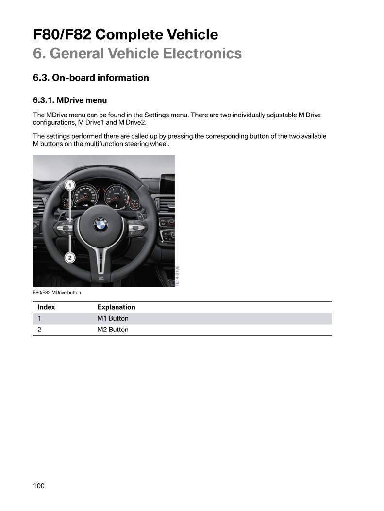
F80/F82�Complete�Vehicle6.�General�Vehicle�Electronics
100
6.3.�On-board�information
6.3.1.�MDrive�menuThe�MDrive�menu�can�be�found�in�the�Settings�menu.�There�are�two�individually�adjustable�M�Driveconfigurations,�M�Drive1�and�M�Drive2.
The�settings�performed�there�are�called�up�by�pressing�the�corresponding�button�of�the�two�availableM�buttons�on�the�multifunction�steering�wheel.
F80/F82�MDrive�button
Index Explanation1 M1�Button2 M2�Button

F80/F82�Complete�Vehicle6.�General�Vehicle�Electronics
101
There�are�two�M�buttons�on�the�steering�wheel�thus�enabling�two�different�settings�to�be�saved�andcalled�up.
The�activation�of�an�MDrive�configuration�is�displayed�by�an�M1�or�M2�symbol�in�the�instrumentcluster.�The�corresponding�symbol�flashes�if�for�example�ABS�or�DSC�adjust�upon�activation�ofrequest.�A�renewed�activation�is�only�possible�if�the�control�is�completed.
F80/F82�MDrive�combination�display
During�the�journey�a�requested�configuration�can�be�temporarily�changed�at�any�time�until�"IgnitionOFF".�The�corresponding�driving�dynamics�button�must�be�operated.�The�M1�or�M2�symbol�in�theinstrument�cluster�goes�out.
An�efficient/comfortable�configuration�is�set�by�default�in�the�factory�for�the�M1�button�and�a�sportyconfiguration�for�the�M2�button.�This�setting�can�be�adapted�in�the�MDrive�menu�to�the�customer'sneeds�and�also�reset�again�to�the�factory�setting.�Each�M�button�is�individually�configurable�and�theoverall�configuration�is�also�assigned�to�the�vehicle�remote�control�being�used.
If�the�DSC�selection�"MDM"�or�"DSC�OFF"�is�chosen,�a�repeated,�i.e.�second�operation,�of�thecorresponding�M�button�is�required�for�activation�of�the�configuration�for�approval�reasons.
F80/F82�MDrive�menu,�DCS�confirmation

F80/F82�Complete�Vehicle6.�General�Vehicle�Electronics
102
New�approval�requirements�require�an�additional�confirmation,�if�the�MDrive�configuration�includes"DSC�MDM"�or�"DSC�OFF".
The�following�functions�and�configurations�can�be�selected�and�set:
Dynamic�Stability�Control�(DSC)
• ON• MDM• OFF
Engine�dynamics�control�incl.�ASD�(Active�Sound�Design)
• Sport�+• Sport• Efficient
Electronic�Damper�Control
• Sport�+• Sport• Comfort
M�Servotronic�(EPS)
• Sport�+• Sport• Comfort
Head‐Up�Display
• M�view• Unchanged
Drivelogic
• Drivelogic�program�"S"�switch�position�(bar)�1-3• Drivelogic�program�"D"�switch�position�(bar)�1-3

F80/F82�Complete�Vehicle6.�General�Vehicle�Electronics
103
Configuration�quick�save
A�modified�M�setting�or�a�new�M�setting�using�the�drive�dynamic�buttons�can�be�assigned�to�oneof�the�two�M�buttons�on�the�steering�wheel�M1�or�M2.�The�corresponding�M�button�on�the�steeringwheel�must�be�pressed�and�held�for�two�seconds.�The�current�configuration�is�set�and�overwritesany�previously�saved�settings.�This�allows�quick�saving�without�accessing�the�M�Drive�menu.
If�the�driver�is�not�aware�that�holding�down�the�M�button�overwrites�the�current�configuration/setting,this�may�lead�to�an�unjustified�customer�complaint.
Active�configuration
The�individual�driving�stability�controls�can�be�set�by�the�driver�(while�driving)�using�the�assignedbuttons.�Then�one�of�the�two�M�buttons�on�the�steering�wheel�can�be�pressed�and�held�for�2�secondsto�save�the�current�configuration.

F80/F82�Complete�Vehicle6.�General�Vehicle�Electronics
104
6.3.2.�M�instrument�clusterThe�M�instrument�cluster�is�based�on�the�instrument�cluster�high�version�from�the�F3x.�The�respectivescales�of�the�instrument�cluster�are�market-�and�vehicle-specific.
The�following�M-specific�changes�exist�in�comparison�to�the�F3x:
Round�instruments:
• Speed�and�engine�speed�display�correspond�to�the�drive�concept(200�mph�in�20�mph�increments�and�8,000�rpm).
• Typical�M�red�needle,�lighting�of�the�dial�in�white�(also�duringthe�day�without�driving�light),�M�inscription.
F80/F82�instrument�cluster
M-specific�displays:
• MDM�M�dynamic�mode�symbol�in�place�of�the�DTC• M1�=�M�Drive1• M2�=�M�Drive2• Display�of�gear• Display�of�Drivelogic�(bar�symbol�such�as�a�button)• Display�of�system�status:�engine�dynamics,�damper�control�and�Servotronic
In�the�instrument�cluster�the�current�configuration�of�the�engine�dynamics,�damper�control�andServotronic�systems�is�shown�in�the�bottom�part�of�the�rev�counter�field.�This�function�can�be�activatedunder�Settings�in�the�Configuration�menu�display.

F80/F82�Complete�Vehicle6.�General�Vehicle�Electronics
105
The�confirmation�of�the�MDrive�settings�for�DSC,�engine�dynamics,�transmission,�EDC�andServotronic�is�also�done�centrally�in�the�instrument�cluster.
For�setting/adjustment�work�in�the�engine�dynamics,�EDC�and�Servotronic�systems�the�response�ofthe�button�activation�is�also�done�as�a�list�in�the�instrument�cluster.
6.3.3.�Head‐Up�DisplayThe�optional�color�head-up�display,�depending�on�the�national-market�version,�can�switch�to�theM-specific�display.
The�following�information/parameters�can�be�shown:
• Shift�point�indicator�by�Shift-light�function• Engine�speed�over�rev�counter�range• Transmission�shift�level• Vehicle�speed• Speed�limit�information�(optional�equipment)• Warnings�same�as�F3x
F80/F82�Head‐Up�Display
The�M-specific�display�for�corresponding�configuration�in�the�MDrive�menu�is�activated�via�theM�button�on�the�steering�wheel�or�by�selecting�it�from�the�Head-Up�configuration�menu.
6.3.4.�Active�Sound�DesignThe�Active�Sound�Design�(ASD)�is�described�in�a�separate�Technical�Reference�Manual�ST1204Active�Sound�Design.

F80/F82�Complete�Vehicle6.�General�Vehicle�Electronics
106
6.3.5.�M�Lap�Timer�appThis�free�app�is�an�add-on�for�ambitious�driving�on�the�race�track�and�enables�precise�analysis�of�thepersonal�driving�style.
The�smartphone�with�the�installed�BMW�M�Lap�Timer�app�is�connected�to�the�vehicle�via�a�USB�cableor�the�appropriate�snap-in�adapter.
The�BMW�M�Lap�Timer�app�not�only�records�acceleration,�braking�points,�lap�times�and�high�forces.The�data�is�prepared�in�the�form�of�graphics,�the�journey�is�played�back�with�the�real�values�as�a�virtualtest�drive.
In�addition,�the�journeys�of�different�drivers�can�be�analyzed�and�compared.
F80/F82�M�Lap�Timer�app

F80/F82�Complete�Vehicle7.�Brief�Overview�of�Equipment
107
7.1.�F80/F82�standard�equipment• M�TwinPower�turbo�engine�and�M�engine�dynamics�button• M�instrument�cluster• MDrive�menu• M�dynamic�mode�(MDM)�with�symbol�button• M�Servotronic�(EPS)• M�bucket�seats�for�driver�and�front�passenger�with�integrated�head�restraints
and�M�moulding�in�the�shoulder�region�illuminates�the�front,�center�consoleincluding�armrest,�armrests�of�doors�in�leather
• M�interior�trim�finishers• M�leather�steering�wheel�with�two�M�multifunction�buttons• M�side�gill,�M�door�sill�cover�strip,�M�driver�footrest• M3/M4�Coupe�Aerodynamic�package:�Front�and�rear�bumpers,�front�fender�with
extensions�and�gills,�exterior�mirror,�side�sill,�adapted�wheel�arches�at�rear�and�front• M3/M4�Coupe�inscription�at�the�rear-wheel�drive,�front�grill�and�in�the�gills• M�exhaust�tailpipe,�right�and�left,�double,�round,�chromium-plated• M�BMW�light-alloy�wheels,�double�spoke,�513M,�18"�currently�with
Michelin�Pilot�Super�Sport�mixed�tires• Combined�allover�heat/sun�protection�glazing• M4�Coupe-specific�trunk�lid• M3-specific�rear�spoiler
7.1.1.�Paint�colors
• Alpine�White• Mineral�White�metallic• Silverstone�metallic• Mineral�grey�metallic• Black�sapphire�metallic• Yas�Marina�blue�metallic• Sakhir�orange�metallic• Austin�yellow�metallic

F80/F82�Complete�Vehicle7.�Brief�Overview�of�Equipment
108
7.1.2.�Leather�colors
• Silverstone�grey• Sakhir�Orange• Sonoma�Beige• Black• BMW�Individual�leather�trims
7.1.3.�Interior�trims
• Aluminium�Blade• Blue�Shadow• Carbon• Fine-line�Anthracite�wood�trim• BMW�Individual�interior�trims


Bayerische�Motorenwerke�AktiengesellschaftQualifizierung�und�TrainingRöntgenstraße�785716�Unterschleißheim,�Germany