Embed Size (px)
Citation preview

HTC-3140LBLink-Belt Cranes
Technical DataSpecifications & Capacities
Telescopic Boom Truck Crane140 US ton
120 metric ton
CAUTION: This material is supplied for
reference use only. Operator must refer to
in---cab Crane Rating Manual and Operator’s
Manual to determine allowable crane lifting
capacities and assembly and operating
procedures.
ENGINEHEATERWARNINGKeep clear ofmoving partsto prevent seriousbodily injury.43P0056
47P0144

5601 (supersedes 5573)---1011--- J8LB
HTC-3140LB Link-Belt Cranes

5601 (supersedes 5573)---1011--- J8LB
HTC-3140LBLink-Belt Cranes
Table Of ContentsBoom, Attachments, and Upper Structure 1. . . . . . . . . . . . . . . . . . . . . . . . . . . . . . . . . . . . . . . . . . . . . . . . . . . .
Boom 1. . . . . . . . . . . . . . . . . . . . . . . . . . . . . . . . . . . . . . . . . . . . . . . . . . . . . . . . . . . . . . . . . . . . . . . . . . . . . . . . . . . .
Boom Wear Pads 1. . . . . . . . . . . . . . . . . . . . . . . . . . . . . . . . . . . . . . . . . . . . . . . . . . . . . . . . . . . . . . . . . . . . . . . . .
Boom Head 1. . . . . . . . . . . . . . . . . . . . . . . . . . . . . . . . . . . . . . . . . . . . . . . . . . . . . . . . . . . . . . . . . . . . . . . . . . . . .
Boom Elevation 1. . . . . . . . . . . . . . . . . . . . . . . . . . . . . . . . . . . . . . . . . . . . . . . . . . . . . . . . . . . . . . . . . . . . . . . . . .
Auxiliary Lifting Sheave --- Optional 1. . . . . . . . . . . . . . . . . . . . . . . . . . . . . . . . . . . . . . . . . . . . . . . . . . . . . . . . .
Hook Blocks and Balls --- Optional 1. . . . . . . . . . . . . . . . . . . . . . . . . . . . . . . . . . . . . . . . . . . . . . . . . . . . . . . . . .
Fly --- Optional 1. . . . . . . . . . . . . . . . . . . . . . . . . . . . . . . . . . . . . . . . . . . . . . . . . . . . . . . . . . . . . . . . . . . . . . . . . . .
Fly Extensions --- Optional 1. . . . . . . . . . . . . . . . . . . . . . . . . . . . . . . . . . . . . . . . . . . . . . . . . . . . . . . . . . . . . . . . .
Upper Operator’s Cab and Controls 2. . . . . . . . . . . . . . . . . . . . . . . . . . . . . . . . . . . . . . . . . . . . . . . . . . . . . . . . . .
Swing 3. . . . . . . . . . . . . . . . . . . . . . . . . . . . . . . . . . . . . . . . . . . . . . . . . . . . . . . . . . . . . . . . . . . . . . . . . . . . . . . . . . . .
Electrical 3. . . . . . . . . . . . . . . . . . . . . . . . . . . . . . . . . . . . . . . . . . . . . . . . . . . . . . . . . . . . . . . . . . . . . . . . . . . . . . . . .
Load Hoist System 4. . . . . . . . . . . . . . . . . . . . . . . . . . . . . . . . . . . . . . . . . . . . . . . . . . . . . . . . . . . . . . . . . . . . . . . . .
Load Hoist Performance 4. . . . . . . . . . . . . . . . . . . . . . . . . . . . . . . . . . . . . . . . . . . . . . . . . . . . . . . . . . . . . . . . . . .
2M Main (Front) and Optional Auxiliary (Rear) Winches 4. . . . . . . . . . . . . . . . . . . . . . . . . . . . . . . . . . . . . . .
Hydraulic System 5. . . . . . . . . . . . . . . . . . . . . . . . . . . . . . . . . . . . . . . . . . . . . . . . . . . . . . . . . . . . . . . . . . . . . . . . . .
Pump Drive 5. . . . . . . . . . . . . . . . . . . . . . . . . . . . . . . . . . . . . . . . . . . . . . . . . . . . . . . . . . . . . . . . . . . . . . . . . . . . . . .
Fuel Tank 5. . . . . . . . . . . . . . . . . . . . . . . . . . . . . . . . . . . . . . . . . . . . . . . . . . . . . . . . . . . . . . . . . . . . . . . . . . . . . . . . .
Engine 5. . . . . . . . . . . . . . . . . . . . . . . . . . . . . . . . . . . . . . . . . . . . . . . . . . . . . . . . . . . . . . . . . . . . . . . . . . . . . . . . . . .
Counterweight 5. . . . . . . . . . . . . . . . . . . . . . . . . . . . . . . . . . . . . . . . . . . . . . . . . . . . . . . . . . . . . . . . . . . . . . . . . . . .
Carrier 7. . . . . . . . . . . . . . . . . . . . . . . . . . . . . . . . . . . . . . . . . . . . . . . . . . . . . . . . . . . . . . . . . . . . . . . . . . . . . . . . . . . .
General 7. . . . . . . . . . . . . . . . . . . . . . . . . . . . . . . . . . . . . . . . . . . . . . . . . . . . . . . . . . . . . . . . . . . . . . . . . . . . . . . . . . .
Outriggers 7. . . . . . . . . . . . . . . . . . . . . . . . . . . . . . . . . . . . . . . . . . . . . . . . . . . . . . . . . . . . . . . . . . . . . . . . . . . . . . . .
Steering and Axles 7. . . . . . . . . . . . . . . . . . . . . . . . . . . . . . . . . . . . . . . . . . . . . . . . . . . . . . . . . . . . . . . . . . . . . . . . .
Suspension 7. . . . . . . . . . . . . . . . . . . . . . . . . . . . . . . . . . . . . . . . . . . . . . . . . . . . . . . . . . . . . . . . . . . . . . . . . . . . . . .
Ground Control Outrigger/Suspension Controls 7. . . . . . . . . . . . . . . . . . . . . . . . . . . . . . . . . . . . . . . . . . . . . . .
Tires and Wheels 7. . . . . . . . . . . . . . . . . . . . . . . . . . . . . . . . . . . . . . . . . . . . . . . . . . . . . . . . . . . . . . . . . . . . . . . . . .
Brakes 7. . . . . . . . . . . . . . . . . . . . . . . . . . . . . . . . . . . . . . . . . . . . . . . . . . . . . . . . . . . . . . . . . . . . . . . . . . . . . . . . . . .
Electrical 7. . . . . . . . . . . . . . . . . . . . . . . . . . . . . . . . . . . . . . . . . . . . . . . . . . . . . . . . . . . . . . . . . . . . . . . . . . . . . . . . .
Engine 8. . . . . . . . . . . . . . . . . . . . . . . . . . . . . . . . . . . . . . . . . . . . . . . . . . . . . . . . . . . . . . . . . . . . . . . . . . . . . . . . . . .
Transmission 8. . . . . . . . . . . . . . . . . . . . . . . . . . . . . . . . . . . . . . . . . . . . . . . . . . . . . . . . . . . . . . . . . . . . . . . . . . . . . .
Fuel Tank 8. . . . . . . . . . . . . . . . . . . . . . . . . . . . . . . . . . . . . . . . . . . . . . . . . . . . . . . . . . . . . . . . . . . . . . . . . . . . . . . . .
Hydraulic System 8. . . . . . . . . . . . . . . . . . . . . . . . . . . . . . . . . . . . . . . . . . . . . . . . . . . . . . . . . . . . . . . . . . . . . . . . . .
Pump Drive 8. . . . . . . . . . . . . . . . . . . . . . . . . . . . . . . . . . . . . . . . . . . . . . . . . . . . . . . . . . . . . . . . . . . . . . . . . . . . . . .
Carrier Speeds and Gradeability 8. . . . . . . . . . . . . . . . . . . . . . . . . . . . . . . . . . . . . . . . . . . . . . . . . . . . . . . . . . . . .
Lower Cab and Controls 9. . . . . . . . . . . . . . . . . . . . . . . . . . . . . . . . . . . . . . . . . . . . . . . . . . . . . . . . . . . . . . . . . . . .
Additional Equipment 9. . . . . . . . . . . . . . . . . . . . . . . . . . . . . . . . . . . . . . . . . . . . . . . . . . . . . . . . . . . . . . . . . . . . . .
Axle Loads 10. . . . . . . . . . . . . . . . . . . . . . . . . . . . . . . . . . . . . . . . . . . . . . . . . . . . . . . . . . . . . . . . . . . . . . . . . . . . . . . .
Axle Loads with 2--Axle or 3--Axle Boom Dolly 11. . . . . . . . . . . . . . . . . . . . . . . . . . . . . . . . . . . . . . . . . . . . . . .
General Dimensions 12. . . . . . . . . . . . . . . . . . . . . . . . . . . . . . . . . . . . . . . . . . . . . . . . . . . . . . . . . . . . . . . . . . . . . . . .
Working Range Diagram 13. . . . . . . . . . . . . . . . . . . . . . . . . . . . . . . . . . . . . . . . . . . . . . . . . . . . . . . . . . . . . . . . . . . .
Boom Extend Modes 14. . . . . . . . . . . . . . . . . . . . . . . . . . . . . . . . . . . . . . . . . . . . . . . . . . . . . . . . . . . . . . . . . . . . . . .

5601 (supersedes 5573)---1011--- J8LB
HTC---3140LB Link---Belt Cranes
Main Boom Lift Capacity Charts -- Standard 15. . . . . . . . . . . . . . . . . . . . . . . . . . . . . . . . . . . . . . . . . . . . . . . . .
20,000 lb Counterweight --- Fully Extended Outriggers --- 360° Rotation 15. . . . . . . . . . . . . . . . . . . . . . . . . . .
Main Boom Lift Capacity Charts -- Optional 16. . . . . . . . . . . . . . . . . . . . . . . . . . . . . . . . . . . . . . . . . . . . . . . . . .
60,000 lb Counterweight --- Fully Extended Outriggers --- 360° Rotation 16. . . . . . . . . . . . . . . . . . . . . . . . . . .
Manual Offset Fly Attachment Lift Capacity Charts -- Optional 17. . . . . . . . . . . . . . . . . . . . . . . . . . . . . . . . .
20,000 lb Counterweight --- Fully Extended Outriggers --- 360° Rotation 17. . . . . . . . . . . . . . . . . . . . . . . . . . .
Main Boom + 10 ft Manual Offset Fly (2° , 15° , 30° , 45° Offsets) 17. . . . . . . . . . . . . . . . . . . . . . . . . . . . . . .
60,000 lb Counterweight --- Fully Extended Outriggers --- 360° Rotation 18. . . . . . . . . . . . . . . . . . . . . . . . . . .
Main Boom + 10 ft Manual Offset Fly (2° , 15° , 30° , 45° Offsets) 18. . . . . . . . . . . . . . . . . . . . . . . . . . . . . . .
20,000 lb Counterweight --- Fully Extended Outriggers --- 360° Rotation 19. . . . . . . . . . . . . . . . . . . . . . . . . . .
155.0 ft Main Boom Length + 31 ft & 55 ft Manual Offset Fly (2° , 15° , 30° , 45° Offsets) 19. . . . . . . . . . .
60,000 lb Counterweight --- Fully Extended Outriggers --- 360° Rotation 20. . . . . . . . . . . . . . . . . . . . . . . . . . .
155.0 ft Main Boom Length + 31 ft & 55 ft Manual Offset Fly (2° , 15° , 30° , 45° Offsets) 20. . . . . . . . . . .
20,000 lb Counterweight --- Fully Extended Outriggers --- 360° Rotation 21. . . . . . . . . . . . . . . . . . . . . . . . . . .
195.3 ft Main Boom Length + 31 ft & 55 ft Manual Offset Fly (2° , 15° , 30° , 45° Offsets) 21. . . . . . . . . . .
60,000 lb Counterweight --- Fully Extended Outriggers --- 360° Rotation 22. . . . . . . . . . . . . . . . . . . . . . . . . . .
195.3 ft Main Boom Length + 31 ft & 55 ft Manual Offset Fly (2° , 15° , 30° , 45° Offsets) 22. . . . . . . . . . .
60,000 lb Counterweight --- Fully Extended Outriggers --- 360° Rotation 23. . . . . . . . . . . . . . . . . . . . . . . . . . .
155.0 ft Main Boom Length + 73 ft, 91 ft, & 109 ft Manual Offset Fly (2° , 15° , 30° , 45° Offsets) 23. . . .
195.3 ft Main Boom Length + 73 ft, 91 ft, & 109 ft Manual Offset Fly (2° , 15° , 30° , 45° Offsets) 24. . . .
Hydraulic Offset Fly Attachment Lift Capacity Charts -- Optional 25. . . . . . . . . . . . . . . . . . . . . . . . . . . . . . .
20,000 lb Counterweight --- Fully Extended Outriggers --- 360° Rotation 25. . . . . . . . . . . . . . . . . . . . . . . . . . .
Main Boom + 10 ft Hydraulic Offset Fly (2° ---45° Offsets) 25. . . . . . . . . . . . . . . . . . . . . . . . . . . . . . . . . . . . . .
60,000 lb Counterweight --- Fully Extended Outriggers --- 360° Rotation 26. . . . . . . . . . . . . . . . . . . . . . . . . . .
Main Boom + 10 ft Hydraulic Offset Fly (2° ---45° Offsets) 26. . . . . . . . . . . . . . . . . . . . . . . . . . . . . . . . . . . . . .
20,000 lb Counterweight --- Fully Extended Outriggers --- 360° Rotation 27. . . . . . . . . . . . . . . . . . . . . . . . . . .
155.0 ft Main Boom Length + 31 ft & 55 ft Hydraulic Offset Fly (2° ---45° Offsets) 27. . . . . . . . . . . . . . . . .
60,000 lb Counterweight --- Fully Extended Outriggers --- 360° Rotation 28. . . . . . . . . . . . . . . . . . . . . . . . . . .
155.0 ft Main Boom Length + 31 ft & 55 ft Hydraulic Offset Fly (2° ---45° Offsets) 28. . . . . . . . . . . . . . . . .
20,000 lb Counterweight --- Fully Extended Outriggers --- 360° Rotation 29. . . . . . . . . . . . . . . . . . . . . . . . . . .
195.3 ft Main Boom Length + 31 ft & 55 ft Hydraulic Offset Fly (2° ---45° Offsets) 29. . . . . . . . . . . . . . . . .
60,000 lb Counterweight --- Fully Extended Outriggers --- 360° Rotation 30. . . . . . . . . . . . . . . . . . . . . . . . . . .
195.3 ft Main Boom Length + 31 ft & 55 ft Hydraulic Offset Fly (2° ---45° Offsets) 30. . . . . . . . . . . . . . . . .
60,000 lb Counterweight --- Fully Extended Outriggers --- 360° Rotation 31. . . . . . . . . . . . . . . . . . . . . . . . . . .
155.0 ft Main Boom Length + 73 ft, 91 ft, & 109 ft Hydraulic Offset Fly (2° ---45° Offsets) 31. . . . . . . . . . .
195.3 ft Main Boom Length + 73 ft, 91 ft, & 109 ft Hydraulic Offset Fly (2° ---45° Offsets) 32. . . . . . . . . . .

15601 (supersedes 5573)---1011--- J8LB
HTC-3140LBLink-Belt Cranes
Boom, Attachments, and Upper Structure���� BoomDesign --- Six section, formed construction of extra hightensile steel consisting of one base section and five tele-scoping sections. The two plate design of each section has
multiple longitudinal bends for superior strength. Each tele-scoping section extends independently by means of onedouble---acting, single stage hydraulic cylinder with integ-
rated holding valves.
Boom� 42.3---195.3 ft (12.9 ---59.5m) six section boom� Integral boom dolly connection� Five boom extend modes (EM1 through EM5), controlled
from the operator’s cab, provide superior capacities byvarying the extension of the telescoping sections:� EM1 extends to 195.3 ft (59.5m)
� EM2 extends to 180.3 ft (55.0m)� EM3 extends to 155.0 ft (47.2m)� EM4 extends to 129.6 ft (39.5m)
� EM5 extends to 103.7 ft (31.6m)� Mechanical boom angle indicator� Wind speed indicator� Maximum tip height for each extend mode is:� EM1 is 204 ft (62.2m)� EM2 is 189 ft (57.6m)� EM3 is 164 ft (50.0m)� EM4 is 139 ft (42.4m)� EM5 is 113 ft (34.4m)
Boom Wear Pads� Wear pads with Teflon inserts that self ---lubricate the
boom sections� Bottom wear pads are universal for T2, T3, T4, and T5
boom sections� Bottom wear pads are universal for the base and T1
boom sections� Top wear pads are universal for all boom sections
Boom Head� Six 16.38 in (41.6cm) root diameter nylon sheaves to han-
dle up to twelve parts of line� Easily removable wire rope guards� Rope dead end lugs on each side of the boom head� Boom head is designed for quick---reeve of the hook
block
Boom Elevation� One double acting hydraulic cylinder with integral hold-
ing valve� Boom elevation: ---2.5° to 80°
Auxiliary Lifting Sheave --- Optional� Single 16.38 in (41.6m) root diameter nylon sheave� Easily removable wire rope guards� Does not affect erection of the fly or use of the main head
sheaves
Hook Blocks and Balls --- Optional� 140 ton (127.0mt) 7 sheave quick---reeve hook block with
safety latch� 100 ton (90.7mt) 6 sheave quick---reeve hook block with
safety latch� 80 ton (72.6mt) 5 sheave quick---reeve hook block with
safety latch� 50 ton (45.4mt) 4 sheave quick---reeve hook block with
safety latch� 35 ton (31.8mt) 1 sheave quick---reeve hook block with
safety latch� 12 ton (10.9mt) hook ball (swivel) with safety latch
Fly --- Optional� 31---55 ft (9.4 ---16.7m) two piece bi---fold lattice fly, stow-
able, offsettable to 2° , 15° , 30° , and 45° . Maximum tipheight is 258 ft (78.6m).
� 10---31 ft---55 ft (3.0 ---9.4 ---16.7m) three piece bi---fold lat-tice fly, stowable, offsettable to 2° , 15° , 30° , and 45° .Maximum tip height is 258 ft (78.6m).
� 10 ft---31 ft---55 ft (3.0 ---9.4 ---16.7m) three piece bi---foldlattice fly, stowable, hydraulically offsettable to 2° through45° . Maximum tip height is 258 ft (78.6m).
Fly Extensions --- Optional� One 18 ft (5.5m) lattice extension, equipped with two
16.38 in (41.6cm) root diameter nylon sheaves, to bemounted between the boom head and fly options. Maxi-mum tip height is 276 ft (84.1m). Minimum of 32,000 lb(14 515kg) of counterweight required.
� Two 18 ft (5.5m) lattice extensions, one equipped withtwo 16.38 in (41.6cm) root diameter nylon sheaves, to bemounted between the boom head and fly options. Maxi-mum tip height is 293 ft (89.3m). Minimum of 32,000 lb(14 515kg) of counterweight required.
� Three 18 ft (5.5m) lattice extensions, one equipped withtwo 16.38 in (41.6cm) root diameter nylon sheaves, to bemounted between the boom head and fly options. Maxi-mum tip height is 311 ft (94.8m). Minimum of 32,000 lb(14 515kg) of counterweight required.

2 5601 (supersedes 5573)---1011--- J8LB
HTC-3140LB Link-Belt Cranes
���� Upper Operator’s Cab and ControlsEnvironmental Cab --- Fully enclosed, one person cab ofgalvaneal steel structure with acoustical insulation.Equipped with:� Tilting cab up to 20°� Seat belt� Tinted and tempered glass windows� Five way adjustable, cushioned seat with headrests, and
seat belt� Extra---large fixed front window with windshield wiper and
washer� Swing up roof window with windshield wiper� Sliding left side door with large fixed window� Sliding right side window for ventilation� Engine dependent warm --- water heater with air ducts for
front windshield defroster and cab floor� Defroster fan for the front window� Bubble level� Circulating fan� Sun screen� Dome light� Cup holder� Fire extinguisher� Left side viewing mirror� Two position travel swing lock
Air Conditioning --- Integral with cab heating system utiliz-ing the same ventilation outlets
Armrest Controls --- Two dual axis electronic joystick con-trollers or optional single axis electronic controllers for:� Swing� Boom hoist� Main front winch� Auxiliary rear winch --- optional� Drum rotation indication� Drum rotation indicator activation switch� Winch high/low speed disable switch(es)� Cab heater and A/C controls� Throttle lock switch� Throttle set/resume switch� Cab tilt switch� Counterweight handling switch� Warning horn button� Swing park brake
Foot Controls� Boom Telescope� Swing brake� Engine throttle
Right Front Console --- Controls and indicators for:� Warning horn button� Function disable switch� Cab floodlights switch� Console dimmer switch� 2---12 volt accessory outlet (Switched & Unswitched)� Emergency engine shutdown� Windshield wiper/washer switch� Outrigger keypad� Upper ignition switch� Lower ignition switch� DPF regeneration inhibit switch� DPF regeneration initiate switch� Boom floodlights switch --- optional� Rotating beacon/strobe light switch --- optional� Hydraulic offset fly switch --- optional
Cab Instrumentation --- Ergonomically positioned LCDdisplay, CANBUS instrumentation for crane operation in-cluding:� Tachometer� Change filter indication� Engine water temperature� Fuel level� Hydraulic oil temperature� Stop engine� Check engine� Wait to start� High exhaust temperature light� DPF regeneration light� Regeneration Disabled light� Swing park brake light� Fine metering function set & %� Engine speed� Engine oil pressure� Battery voltage� Engine hours� Fuel rate (gal/hr)� Engine load� Third wrap indicator activation & setup� Engine Diagnostics� Electronic Control Diagnostics� Outrigger level indicator� Charge filter indicator
Diagnostic Center --- Located on the left side of the frontpanel below the windshield� Engine diagnostic� RCL CANBUS diagnostic� Boom CANBUS diagnostic� Crane Controller USB diagnostic� RCL controller USB diagnostic� Manual boom control connection� Manual crane control connection

35601 (supersedes 5573)---1011--- J8LB
HTC-3140LBLink-Belt Cranes
Link-Belt Pulse – The Link-Belt in-house designed, totalcrane operating system that utilizes the display as areadout and operator interface for the following systems:� Rated capacity limiter – LCD graphic audio – visual
warning system integrated into the dash with anti – twoblock and function limiter. Operating data includes:� Crane configuration� Boom length and angle� Boom head height� Allowed load and % of allowed load� RCL light bar� Boom angle� Radius of load� Actual load� Wind speed� Unit Conversion� Multiple language capabilities� Highlighted unit of measurement on working screen� Active pin/latch status� Telescope operation displayed in real time� Counterweight installation/removal� Third wrap indicator� Diagnostics� Operator settable alarms (include):� Maximum and minimum boom angles� Maximum tip height� Maximum boom length� Swing left/right positions� Operator defined area (imaginary plane)� Outrigger position sensing
� Extend control module (ECM)� Controls the extend modes� Diagnostics
� Electronic controllers� Controls all load lifting functions� Diagnostics
� Fine metering� Controls the initial reaction speeds of the main and
auxiliary winches, boom hoist, and swing functions� Diagnostics
External RCL Light Bar --- Optional --- Visually informs theground crew when crane is approaching maximum loadcapacity with a series of green, yellow, and red lights.
Internal RCL Light Bar --- Optional --- Visually informs theoperator when crane is approaching maximum load capa-city with a series of green, yellow, and red lights.
���� SwingMotor/Planetary --- Bi ---directional hydraulic swing motormounted to a planetary reducer for 360° continuoussmooth swing at 1.5 rpm.
Swing Park Brake --- 360° , electric over hydraulic, (springapplied/hydraulic released) multi ---disc brake mounted onthe speed reducer. Operated by a switch from the opera-
tor’s cab.
Swing Brake --- 360° , foot operated, hydraulic applied discbrake mounted to the speed reducer.
Swing Lock --- Two---position swing lock (boom over frontor rear) operated from the operator’s cab.
360° Positive Swing Lock --- Optional --- Meets New York
City requirement.
���� ElectricalSwing Alarm --- Audio/visual warning device signals whenthe upper is swinging.
Lights� Two working lights on front of the cab� One rotating amber beacon on top of the cab --- optional� One amber strobe beacon on top of the cab --- optional� Boom floodlight --- optional

4 5601 (supersedes 5573)---1011--- J8LB
HTC-3140LB Link-Belt Cranes
���� Load Hoist SystemLoad Hoist Performance
Main (Front) and Auxiliary (Rear) Winches --- 7/8 in (22mm) Rope
Maximum Line Pull Normal Line Speed High Line Speed Layer Total
Layer lb kg ft/min m/min ft/min m/min ft m ft m
1 21,022 9 535.4 137 41.7 272 82.9 125 38.1 125 38.1
2 18,985 8 611.9 152 46.3 301 91.7 138 42.0 263 80.2
3 17,280 7 838.0 167 50.9 331 100.8 152 46.3 415 126.5
4 15,868 7 197.6 182 55.4 360 109.7 165 50.3 588 179.2
5 14,669 6 653.7 197 60.0 390 118.8 179 54.6 759 231.3
6 13,639 6 186.5 212 64.6 419 127.7 192 58.5 951 289.9
Wire Rope ApplicationDiameter
Type
MaximumPermissible Load
in mm lb kg
Main (Front)Winch
Standard 7/8 22 18x19 rotation resistant --- right regular lay (Type RB) 17,520 7 946.9
Optional 7/8 22 4 strand, low torque --- right regular lay ( Type GC) 30,285 13 737.0
Optional 7/8 22 36x7 rotation resistant --- right regular lay (Type ZB) 20,920 9 489.2
Auxiliary (Rear)Winch
Standard 7/8 22 18x19 rotation resistant --- right regular lay (Type RB) 17,520 7 946.9
Optional 7/8 22 4 strand, low torque --- right regular lay ( Type GC) 30,285 13 737.0
Optional 7/8 22 36x7 rotation resistant --- right regular lay (Type ZB) 20,920 9 489.2
2M Main (Front) and Optional Auxiliary(Rear) Winches� Axial piston, full and half displacement (2---speed) motors
driven through planetary reduction unit for positive con-trol under all load conditions.
� Grooved lagging� Power up/down mode of operation� Hoist drum cable follower --- optional� Drum rotation indicator� Drum diameter: 15 in (38.1cm)� Rope length:� Main (Front): 900 ft (274.3m)� Auxiliary (Rear): 675 ft (205.7m) or 900 ft (274.3m)
� Maximum rope storage: 951 ft (289.9m)� Terminator style socket and wedge
Third wrap indicator --- optional --- Visually and audiblywarns the operator when the wire rope is on the first (bot-tom) layer and when the wire rope is down to the last three
wraps.

55601 (supersedes 5573)---1011--- J8LB
HTC-3140LBLink-Belt Cranes
���� Hydraulic SystemAll functions are hydraulically powered allowing positiveprecise control with independent or simultaneous operationof all functions.
Main Pumps� One, three section gear pump for the boom hoist, tele-
scope, swing, and charge circuits.� Two, closed---loop piston pumps are mounted to the rear
of the pump drive. The front pump drives the front winchand the rear pump drives the optional rear winch.
� One, pressure compensated piston pump mounted tothe rear of the rear winch pump supplies hydraulic powerto the controls, counterweight handling, and hydraulicallyoffsettable fly (optional) circuits.
Hydraulic Reservoir --- 155 gal (586.7L) capacity equippedwith sight level gauge. Diffusers built in for deaeration.
Magnetic drain plug and large internal magnet.
Filtration� One, 7---micron filter located inside hydraulic reservoir,
accessible for easy replacement� One, 7---micron charge filter located next to the reservoir
with an in---cab indicator light� One, magnetic suction strainer located inside the hy-
draulic reservoir
Valve Control “fine inching” Mode --- Special fine meter-ing valve settings, selectable from the operator’s cab, al-lows very slow movements to the main and auxiliarywinches, boom hoist, and swing for precision work.
Counterbalance Valves --- All boom extend cylinders andboom hoist cylinder are equipped with counterbalancevalves to provide load lowering and prevents accidental
load drop when hydraulic power is suddenly reduced.
Hydraulic Oil Cooler --- Remote mounted, removes heatfrom the hydraulic oil.
Boom Hoist Float Valves --- For transporting the boomover the rear of the crane with a boom dolly. Allows hy-draulic oil within the boom hoist cylinder to flow between
piston side and case side.
Swing Brake Release Valve --- For transporting the boomover the rear of the crane with a boom dolly. Holds the
360° swing park brake in the released position allowingfree rotation of the upperstructure.
���� Pump DriveAll pumps are mechanically driven by the diesel engine.
Boom hoist and telescope pumps have an activation delayduring engine start to aid in cold weather starting.
���� Fuel TankOne 60 gal (227.1L) capacity tank
���� Engine
Specification Cummins QSB --- 6.7
Numbers of cylinders 6
Cycle 4
Emissions Compliance Level: Tier 4i/Stage IIIB
Bore and Stroke: inch (mm) 4.21 x 4.88 (107x124)
Piston Displacement: in3 (L) 409 (6.7)
Max. Brake Horsepower: hp (kW) 215 (160) @ 1,800 rpm
Peak Torque: ft lb (Nm) 685 (929.0) @ 1,300 rpm
Alternator: volts --- amps 12 --- 160
Crankcase Capacity: qt (L) 18.4 (17.4)
� 120 V engine block heater
� Complies with EPA emissions standards effective January 2010.
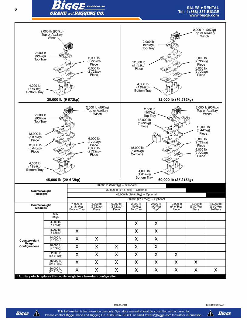
���� CounterweightStandard --- Total of 20,000 lb (9 072kg) consisting of auxili-ary winch or 2,000 lb (907kg) counterweight and four hy-draulically removable counterweights. Assembled and dis-
assembled by hydraulic cylinders controlled from the oper-ator’s cab with capacities for:� 0 lb (0kg) counterweight� 4,000 lb (1 814kg) counterweight� 8,000 lb (3 629kg) counterweight� 14,000 lb (6 350kg) counterweight� 20,000 lb (9 072kg) counterweight
Optional --- 12,000 lb (5 443kg) in addition to standardcounterweight for a total of 32,000 lb (14 515kg) counter-
weight with additional capacities for:� 32,000 lb (14 515kg) counterweight
Optional --- 25,000 lb (11 340kg) in addition to standard
counterweight for a total of 45,000 lb (20 412kg) counter-weight with additional capacities for:� 32,000 lb (14 515kg) counterweight� 45,000 lb (20 412kg) counterweight
Optional --- 40,000 lb (18 144kg) in addition to standardcounterweight for a total of 60,000 lb (27 215kg) with
additional capacities for:� 32,000 lb (14 515kg) counterweight� 45,000 lb (20 412kg) counterweight� 60,000 lb (27 215kg) counterweight*
Low speed jobsite travel is offered for these optional counter-
weight configurations and a boom dolly or boom trailer may
be required for on ---highway travel.
* Overall width of the crane increases to 13 ft 8 in (4.2m)for this counterweight configuration.
6 5601 (supersedes 5573)---1011--- J8LB
HTC-3140LB Link-Belt Cranes
20,000 lb (9 072kg) 32,000 lb (14 515kg)
45,000 lb (20 412kg) 60,000 lb (27 215kg)
4,000 lb(1 814kg)
Bottom Tray
2,000 lb(907kg)Top Tray
2,000 lb (907kg)Top or Auxiliary
Winch
6,000 lb(2 722kg)
Piece
13,000 lb(5 897kg)
Piece
15,000 lb(6 804kg)2---Piece
4,000 lb(1 814kg)
Bottom Tray
2,000 lb(907kg)Top Tray
12,000 lb(5 443kg)
Piece
4,000 lb(1 814kg)
Bottom Tray
2,000 lb(907kg)Top Tray
12,000 lb(5 443kg)
Piece
13,000 lb(5 896kg)
Piece
4,000 lb(1 814kg)
Bottom Tray
2,000 lb(907kg)Top Tray
12,000 lb(5 443kg)
Piece
2,000 lb (907kg)Top or Auxiliary
Winch
2,000 lb (907kg)Top or Auxiliary
Winch
2,000 lb (907kg)Top or Auxiliary
Winch
6,000 lb(2 722kg)
Piece
6,000 lb(2 722kg)
Piece
6,000 lb(2 722kg)
Piece
6,000 lb(2 722kg)
Piece6,000 lb
(2 722kg)Piece
6,000 lb(2 722kg)
Piece
6,000 lb(2 722kg)
Piece
CounterweightPackages
20,000 lb (9 072kg) --- Standard
32,000 lb (14 515kg) --- Optional
45,000 lb (20 412kg) --- Optional
60,000 (27 215kg) --- Optional
CounterweightModules
4,000 lb(1 814kg)
Bottom Tray
6,000 lb(2 722kg)
Piece
6,000 lb(2 722kg)
Piece
2,000 lb(907kg)Top Tray
2,000 lb(907kg)
Top*
12,000 lb(5 443kg)
Piece
13,000 lb(5 897kg)
Piece
15,000 lb(6 804kg)2---Piece
CounterweightUsage
Configurations
0 lb(0kg)
4,000 lb(1 814kg) X X8,000 lb
(3 629kg) X X X14,000 lb(6 350kg) X X X X20,000 lb(9 072kg) X X X X X32,000 lb
(14 515kg) X X X X X X45,000 lb
(20 412kg) X X X X X X X60,000 lb
(27 215kg) X X X X X X X X* Auxiliary winch replaces this counterweight for a two---drum configuration

75601 (supersedes 5573)---1011--- J8LB
HTC-3140LBLink-Belt Cranes
Carrier���� General� 9 ft 10 in (3.0m) wide� 28 ft 1 in (8.56m) wheelbase (centerline of first axle to
centerline of fifth axle)� Frame --- Box---type, torsion resistant, welded construc-
tion made of high tensile steel. Equipped with front andrear towing and tie---down lugs, tow connections, andaccess ladders.
���� OutriggersBoxes --- Two double box, front and rear welded to the car-
rier frame
Beams and Jacks --- Four dual stage beams with ConfinedArea Lifting Capacities (CALC) provide selectable outrigger
extensions of full, intermediate, and retracted positions.Jacks with integral check valves, hydraulically controlledfrom the operator’s cab and on both sides of carrier. A fifth
front bumper outrigger with integral check valves is hydrau-lically controlled from the operator’s cab and at the frontbumper of carrier.
Pontoons --- Four lightweight, stow’n go, 26” (66cm) diameter
steel pontoons with a contact area of 531 in2 (3 425cm2) canbe stored for road travel in either the storage racks on thecarrier or under the outrigger boxes.
Main Jack Reaction --- 160,000 lb (72 575kg) force and301 psi (2 075kPa) ground bearing pressure
���� Steering and Axles� Full integral master gear/slave gear steering system pro-
vides hydraulic assisted steering with mechanical linkbetween steering wheel and wheels
� Drive --- 10 x 6 for on/off ---highway travel� Axle 1 & 2 --- Tandem steered, non---driven� Axle 3,4, & 5 --- Tridem non---steered, driven� Inter---Axle Differential Lock --- Traction adding device
that locks axle 3 with axle 4 and axle 4 with axle 5. Oper-ated by a switch from the carrier cab.
� Transaxle (Cross---axle) Differential Lock --- Tractionadding device that locks differentials within axles 3, 4,and 5. Operated by a switch from the carrier cab.
���� SuspensionHydro---pneumatic, lockable with level adjustment andautomatic ride height leveling. All axles have longitudinaland transverse trailing arms with leveling adjustment and
lockable cylinders. The carrier can be raised and loweredby controls in the carrier cab that adjust the suspensioncylinders.
� Cylinder stroke: ---3.5 in (---88.9mm) / +3.5 in (88.9mm)
���� Ground ControlOutrigger/Suspension ControlsEnvironmentally sealed and ergonomically positioned, con-trol stations located on both sides of the carrier with con-trols for crane operations including:� Starts and stops carrier engine� Throttles carrier engine up and down� Suspension operation including:� Raise suspension on outriggers� Lower suspension on tires� Outrigger operation including:
� Extends and retracts two beams together� Extends and retracts all jacks together� Extend and retract fifth (bumper) outrigger� Automatic leveling on outriggers
� Outrigger lighting� Bubble level
���� Tires and WheelsFront --- Four (single) 445/65R22.5 tires on aluminum disc
wheels
Rear --- Twelve (dual) 12R24.5 tires on aluminum discwheels
� Spare tires and wheels --- optional� Tire inflation kit --- optional
���� BrakesService --- Full air anti ---lock (ABS) brakes on all wheel
ends. Dual circuit compressed air system with air dryer.
Parking/Emergency --- Spring loaded type, acting on 3rd,4th, and 5th axles automatically apply when air pressure
drops below 40 psi (275.8kPa) in both circuits.
Hill Start Aid (HSA) --- Prevents roll ---back or roll ---forwardwhile launching on grades.
���� ElectricalBattery --- Three batteries provide 12 volt starting and op-eration
Lights
� Front lighting includes two main headlights, two highbeam lights, two parking/directional indicators, and threecab marker lights.
� Side lighting includes three parking/directional indicatorsper side.
� Rear lighting includes two parking/directional indicators,two parking/brake lights, two reverse lights, three markerlights, and a license plate light.
� Other equipment includes hazard/warning system, cablights, instrument panel lights, and signal horn.
� One amber strobe beacon on top of the cab --- optional� Daytime running lights --- optional� Outrigger working lights

8 5601 (supersedes 5573)---1011--- J8LB
HTC-3140LB Link-Belt Cranes
���� Engine
Specification Cummins ISX 15
Numbers of cylinders 6
Cycle 4
Bore and Stroke: inch (mm) 5.39 x 6.65 (137x169)
Piston Displacement: in3 (L) 912 (14.9)
Max. Brake Horsepower: hp (kW)581 (434) @ 2,000 rpm
550 (410.0) @ 1,800 rpm
Peak Torque: ft lb (Nm) 1,850 (2 508) @ 1,200 rpm
Alternator: volts --- amps 12 --- 160
Crankcase Capacity: qt (L) 52 (49.2)
� Cruise control
� Three---stage engine compression brake
� Engine driven variable speed fan
� Thermostatically controlled radiator
� 120 V engine block heater
� Ether injection system --- optional
� Complies with EPA emission standards effective January 2010
���� TransmissionMain Transmission --- Automated --- Eaton Ultra Shift Plus(no clutch pedal) transmission with 11 forward gears and 3reverse gears.
Auxiliary Transmission --- Air actuated manual transmis-sion with two gears.
���� Fuel TankOne 95 gal (359.6L) capacity tank
���� Hydraulic SystemAll functions are hydraulically powered allowing positive,precise control with independent or simultaneous operation
of all functions.
Main Pumps� One fixed displacement gear pump for the steering cir-
cuit� One fixed displacement gear pump for suspension and
outriggers� Combined pump capacity of 41 gpm (155.2Lpm)
Hydraulic Reservoir --- 35 gal (132.5L) capacity equippedwith sight level gauge. Diffusers built in for deaeration.
Filtration --- Two 10 micron, full flow, return line filters. Alloil is filtered prior to return to reservoir. Accessible for easyfilter replacement.
���� Pump DriveAll pumps are mechanically driven by the diesel engine.Suspension and outriggers pump is direct mounted to the
PTO at the bottom of the transmission. Steering pump isdirect mounted to the engine.
���� Carrier Speeds and Gradeability
Eaton Ultra Shift Plus SpeedGradeability
(@ peak torque ExceptCreep @ Idle)
Gear RatioHigh Range
(1.00)Low Range
(2.04)% Grade
mph km/h mph km/h Min. Max.
11th 0.73 65.62 105.61 32.16 51.76 1.71 3.49
10th 1.00 47.90 77.09 23.48 37.79 2.93 5.73
9th 1.38 34.71 55.86 17.01 27.37 4.50 8.79
8th 1.95 24.56 39.53 12.04 19.38 6.76 13.32
7th 2.77 17.29 27.83 8.48 13.65 9.96 19.79
6th 3.79 12.64 20.34 6.20 9.98 13.90 27.82
5th 5.23 9.16 14.74 4.49 7.23 19.45 39.13
4th 7.41 6.46 10.40 3.17 5.10 23.34 47.04
3rd 11.85 4.04 6.50 1.98 3.19 29.17 58.92
2nd 16.30 2.94 4.73 1.44 2.32 31.15 62.96
1st 26.08 1.84 2.96 0.90 1.45 38.94 78.85
Reverse (1) 20.84 2.30 3.70 1.13 1.82 33.54 67.85
Reverse (2) 13.03 3.68 5.92 1.80 2.90 20.74 41.72
Reverse (3) 3.43 13.96 22.47 6.29 10.12 6.55 14.13
1st @ Idle 26.08 0.60 0.97 0.32 0.51
2nd @ Idle 16.30 0.96 1.54 0.50 0.80
3rd @ Idle 11.85 1.31 2.11 0.69 1.11
Reverse (1) @ Idle 20.84 0.75 1.21 0.39 0.63
Reverse (2) @ Idle 13.03 1.19 1.92 0.63 1.01
Based on a gross vehicle weight of 117,600 lbs (53 342kg)

95601 (supersedes 5573)---1011--- J8LB
HTC-3140LBLink-Belt Cranes
���� Lower Cab and ControlsEnvironmental Cab --- Fully enclosed, one person cab ofcomposite structure with acoustical insulation. Equippedwith:
� Tinted and tempered glass windows� Roll down left side window for ventilation� Right side window� Intermittent windshield wiper and washer� Six way adjustable and air suspended driver’s seat with
seat belt� Two remote control, heated, rear view mirrors� Engine dependent warm---water heater with air ducts for
windshield defroster and cab floor� Adjustable sun visor� 2 Dome lights� 12 volt accessory jack (switched)� 12 volt accessory jack (unswitched)� Fire extinguisher
Air Conditioning --- Integral with cab heating system utiliz-ing the same ventilation outlets
Cab Instrumentation --- Ergonomically positioned instru-mentation for driving including:� Speedometer with odometer, hour meter, trip meter, and
clock� Tachometer� Front and rear system air pressure with warning indicator� Diesel emissions fluid level with warning indicator
Dash Mounted Controls For:� Carrier lights� Console dimmer switch� Diesel particulate filter switch� Fan override switch� Remote mirror control switches� Mirror heating switch� Cab heater/air conditioning switch� Travel mode switch� Park brake air valve� Trailer brake air valve
Dash Mounted Indicators For:� Turn signal indication� High beam headlights
Dash Mounted LCD Display --- Ergonomically positionedon the right of driver’s front dash panel, digital instrumenta-tion and indicators for crane operations including:
Gauges� Engine water temperature� Engine oil pressure� Fuel level� Voltmeter
Indicator Lights� Check engine� Stop engine� Service engine� Exhaust regeneration� High exhaust temperature� Wait to start� Cruise� Park brake� ABS
� Trailer ABS� Transaxle (cross---axle) differential lock� Inter---axle differential lock� Transfer case� Travel mode� Ride height� Seat belt
Diagnostic Screens� Engine� Transmission� ABS brakes� Suspension� Outriggers
Right Side Console --- Controls and indicators for:� Transmission gear shifting� Transmission digital readout� Cruise controls� Auxiliary transmission range selector switch� Transaxle (cross---axle) differential lock switch with indic-
ator light� Inter---axle differential lock switch with indicator light� Front axles (axles 1 & 2) suspension height switch� Rear axles (axles 3---5) suspension height switch� Ride height switch� 2/12 volt accessory outlet (switched & unswitched)
Steering Column Controls For:� Carrier ignition� Turn signal switch� High beam switch� Steering wheel adjustments� Warning horn� Hazard light switch� Intermittent windshield wiper and washer
Foot Controls For:� Carrier service brakes� Engine throttle
Fuse & Diagnostic Center --- Located inside cab behindseat contains:� Fuses, Relays� Control Modules� Diagnostic ports� Suspension diagnostic� Engine diagnostic� ABS Diagnostic� Cab display diagnostic� Transmission Diagnostic
���� Additional EquipmentStandard:� Aluminum full deck fenders with mud flaps� Two right side aluminum storage boxes� Air hose connection ports� Clearance flags
Optional:
� Pneumatic and electrical quick disconnect connectorsmounted on the rear for trailer or boom dolly brakes andlights
� Rear mounted pintle hook

10 5601 (supersedes 5573)---1011--- J8LB
HTC-3140LB Link-Belt Cranes
Axle Loads
Base crane with full tank of fueland 2,000 lb (907kg) counterweight
Gross Vehicle Weight(1)
Front Axles Rear Axles
lb kg lb kg lb kg
108,618 49 268 42,643 19 343 65,974 29 925
Driver in carrier cab 250 113 311 141 ---61 ---28
Rear pintle hook 44 20 ---23 ---10 67 30
Pneumatic and electrical connectors for trailer or boom dolly 15 7 1 ---1 13 6
Ether injection 6 3 9 4 ---2 1
Remove 2,000 lb (907kg) of ctwt --- for one winch configuration only ---2,039 ---925 1,054 478 ---3,093 ---1 403
Hoist drum follower --- main 101 46 ---43 ---19 144 65
Auxiliary winch with 675 ft (205.7m) of 7/8” (22mm) wire rope 1,185 538 ---555 ---252 1,739 789
Remove auxiliary winch with 675 ft (205.7m) of 7/8” (22mm) wire rope--- for two winch configuration only
---3,019 ---1 369 1,546 701 ---4,565 ---2 071
Hoist drum follower --- auxiliary 101 46 ---57 ---26 158 72
Substitute 675 ft (205.7m) of rope with 900 ft (274.3m) of rope ---auxiliary
378 171 ---173 ---78 551 250
Remove 900 ft (274.3m) of rope from front (main) winch ---1,535 ---696 509 231 ---2,044 ---927
Remove 675 ft (205.7m) of rope from rear (auxiliary) winch ---1,157 ---525 529 240 ---1,686 ---765
360° mechanical swing lock 140 66 23 10 117 53
4,000 lb (1 814kg) counterweight bottom tray on upper 4,000 1 814 ---1,733 ---786 5,733 2 600
6,000 lb (2 722kg) counterweight on upper 6,000 2 722 ---2,599 ---1 179 8,599 3 900
6,000 lb (2 722kg) counterweight on upper 6,000 2 722 ---2,599 ---1 179 8,599 3 900
12,000 lb (5 443kg) counterweight on upper 12,000 5 443 ---5,198 ---2 358 17,198 7 801
13,000 lb (5 897kg) counterweight on upper 13,000 5 897 ---5,632 ---2 555 18,632 8 451
2,000 lb (907kg) counterweight top tray on upper 2,000 907 ---806 ---366 2,806 1 273
Floodlight to the front of boom base section 7 3 11 5 ---4 ---2
Fly mounting brackets to boom base section for fly options 290 132 309 140 ---19 ---9
31---55 ft (9.45---16.76m) offsettable, two---piece (bi--- fold) lattice fly ---stowed
2,734 1 240 2,820 1 279 ---86 ---39
10---31---55 ft (3.05---9.45---16.76m) offsettable, three---piece (bi--- fold)lattice fly --- stowed
3,331 1 511 3,684 1 671 ---353 ---160
10---31---55 ft (3.05---9.45---16.76m) hydraulically offsettable,three---piece (bi--- fold) lattice fly --- stowed
3,804 1 725 4,460 2 023 ---656 ---298
Additional components for hydraulically offsettable fly 469 213 607 275 ---138 ---63
Auxiliary lifting sheave 120 54 223 116 ---103 ---61
35 ton (31.8mt) 1---sheave hook block at front bumper 1,100 499 1,795 814 ---695 ---315
50 ton (45.4mt) 4---sheave hook block at front bumper 1,200 544 1,958 888 ---758 ---344
80 ton (72.6mt) 5---sheave hook block at front bumper 1,411 640 2,302 1 044 ---891 ---404
100 ton (90.7mt) 6---sheave hook block at front bumper 1,750 794 2,855 1 295 ---1,105 ---501
140 ton (127.0mt) 7---sheave hook block at front bumper 2,394 1 086 3,906 1 772 ---1,512 ---686
12 ton (10.9mt) hook ball at front bumper 722 327 1,178 534 ---456 ---207
Counterweight Load TransferFront Axles Rear Axles
lb kg lb kg
Transfer 4,000 lb (1 814kg) counterweight tray to carrier deck 4,664 2 116 ---4,664 ---2 116
Transfer 6,000 lb (2 722kg) counterweight to carrier deck 6,996 3 173 ---6,996 ---3 173
Transfer 6,000 lb (2 722kg) counterweight to carrier deck 6,996 3 173 ---6,996 ---3 173
Transfer 12,000 lb (5 443kg) counterweight to carrier deck 13,992 6 347 ---13,992 ---6 347
Transfer 13,000 lb (5 897kg) counterweight to carrier deck 15,158 6 876 ---15,158 ---6 876
Axle Maximum Load @ 65 mph (105km/h)
Front 49,200 lb (22 317kg) --- aluminum disc wheels with 445/65R22.5 tires
Rear 74,184 lb (33 650kg) --- aluminum disc wheels with 12R24.5 tires
(1) Adjust gross vehicle weight and axle loading according to component weight. All weights are ±3%.
115601 (supersedes 5573)---1011--- J8LB
HTC-3140LBLink-Belt Cranes
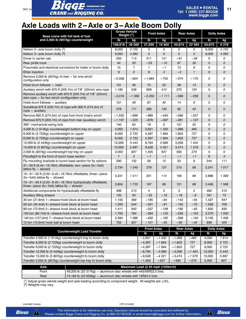
Axle Loads with 2--Axle or 3--Axle Boom Dolly
Base crane with full tank of fueland 2,000 lb (907kg) counterweight
Gross VehicleWeight (1)
Front Axles Rear Axles Dolly Axles
lb kg lb kg lb kg lb kg
108,618 49 268 37,269 16 905 50,674 22 985 20,675 9 378
Nelson 2---axle boom dolly (2) 6,000 2 722 0 0 0 0 6,000 2 722
Nelson 3---axle boom dolly (2) 9,000 4 082 0 0 0 0 9,000 4 082
Driver in carrier cab 250 113 311 141 ---61 ---28 0 0
Rear pintle hook 44 20 ---23 ---10 67 30 0 0
Pneumatic and electrical connectors for trailer or boom dolly 15 7 1 ---1 13 6 0 0
Ether injection 6 3 9 4 ---2 1 0 0
Remove 2,000 lb (907kg) of ctwt --- for one winchconfiguration only
---2,038 ---924 ---1,664 ---755 ---374 ---170 0 0
Hoist drum follower --- main 101 46 73 33 28 13 0 0
Auxiliary winch with 675 ft (205.7m) of 7/8” (22mm) wire rope 1,185 538 909 412 275 125 0 0
Remove auxiliary winch with 675 ft (205.7m) of 7/8” (22mm)wire rope --- for two winch configuration only
---3,019 ---1 369 ---2,450 ---1 111 ---569 ---258 0 0
Hoist drum follower --- auxiliary 101 46 87 40 14 6 0 0
Substitute 675 ft (205.7m) of rope with 900 ft (274.3m) ofrope --- auxiliary
378 171 286 130 92 42 0 0
Remove 900 ft (274.3m) of rope from front (main) winch ---1,535 ---696 ---969 ---440 ---566 ---257 0 0
Remove 675 ft (205.7m) of rope from rear (auxiliary) winch ---1,157 ---525 ---876 ---397 ---281 ---127 0 0
360° mechanical swing lock 140 64 19 9 121 55 0 0
4,000 lb (1 814kg) counterweight bottom tray on upper 4,000 1 814 2,931 1 330 1,069 485 0 0
6,000 lb (2 722kg) counterweight on upper 6,000 2 722 4,397 1 994 1,603 727 0 0
6,000 lb (2 722kg) counterweight on upper 6,000 2 722 4,397 1 994 1,603 727 0 0
12,000 lb (5 443kg) counterweight on upper 12,000 5 443 8,794 3 989 3,206 1 454 0 0
13,000 lb (5 897kg) counterweight on upper 13,000 5 897 9,526 4 321 3,474 1 576 0 0
2,000 lb (907kg) counterweight top tray on upper 2,000 907 1,405 637 595 270 0 0
Floodlight to the front of boom base section 7 3 ---1 ---1 ---1 ---1 8 4
Fly mounting brackets to boom base section for fly options 290 132 26 12 20 9 244 111
31---55 ft (9.45---16.76m) offsettable, two---piece (bi--- fold)lattice fly --- stowed
2,734 1 240 279 127 215 98 2,241 1 017
10---31---55 ft (3.05---9.45---16.76m) offsettable, three---piece(bi--- fold) lattice fly --- stowed
3,331 1 511 251 114 193 88 2,886 1 309
10---31---55 ft (3.05---9.45---16.76m) hydraulically offsettable,three---piece (bi--- fold) lattice fly --- stowed
3,804 1 725 197 89 151 68 3,456 1 568
Additional components for hydraulically offsettable fly 469 213 4 2 3 2 462 210
Auxiliary lifting sheave 120 54 ---23 ---10 ---18 ---8 161 73
35 ton (31.8mt) 1---sheave hook block at boom head 1,100 499 ---185 ---84 ---142 ---64 1,427 647
50 ton (45.4mt) 4---sheave hook block at boom head 1,200 544 ---201 ---91 ---155 ---70 1,556 706
80 ton (72.6mt) 5---sheave hook block at boom head 1,411 640 ---237 ---108 ---182 ---83 1,830 830
100 ton (90.7mt) 6---sheave hook block at boom head 1,750 794 ---294 ---133 ---226 ---103 2,270 1 030
140 ton (127.0mt) 7---sheave hook block at boom head 2,394 1 086 ---402 ---182 ---309 ---140 3,105 1 408
12 ton (10.9mt) hook ball at boom head 722 327 ---121 ---55 ---93 ---42 936 425
Counterweight Load TransferFront Axles Rear Axles Dolly Axles
lb kg lb kg lb kg
Transfer 4,000 lb (1 814kg) counterweight tray to boom dolly ---2,931 ---1 330 ---1,069 ---485 4,000 1 814
Transfer 6,000 lb (2 722kg) counterweight to boom dolly ---4,397 ---1 994 ---1,603 727 6,000 2 722
Transfer 6,000 lb (2 722kg) counterweight to boom dolly ---4,397 ---1 994 ---1,603 727 6,000 2 722
Transfer 12,000 lb (5 443kg) counterweight to boom dolly ---8,794 ---3 989 ---3,206 ---1 454 12,000 5 443
Transfer 13,000 lb (5 897kg) counterweight to boom dolly ---9,526 ---4 321 ---3,474 ---1 576 13,000 5 897
Transfer 2,000 lb (907kg) counterweight top tray to boom dolly ---1,405 ---637 ---595 ---270 2,000 907
Axle Maximum Load @ 65 mph (105km/h)
Front 49,200 lb (22 317kg) --- aluminum disc wheels with 445/65R22.5 tires
Rear 74,184 lb (33 650kg) --- aluminum disc wheels with 12R24.5 tires
(1) Adjust gross vehicle weight and axle loading according to component weight. All weights are ±3%.(2) Weights may vary.

12 5601 (supersedes 5573)---1011--- J8LB
HTC-3140LB Link-Belt Cranes
General Dimensions
Not To Scale
CL OF ROTATION
21.12”(0.54m)
GROUND LEVELWITH CRANE
ON OUTRIGGERS
10.62”(0.27m)
10.50”(0.27m)
Turning Radius English Metric
Wall to wall over carrier 45’ 4.2” 13.82m
Wall to wall over boom 49’ 4” 15.04m
Wall to wall over boom attachment 50’ 6.3” 15.40m
Curb to curb 41’ 7.4” 12.68m
Centerline of tire 40’ 9.9” 12.44m
Tail Swing English Metric
With two winches 15’ 8.6” 4.79m
With counterweight 14’ 11.13” 4.55m
Overall Width English Metric
With up to 45,000 lb (20 412kg) counterweight 9’ 10” 3.00m
With 60,000 lb (27 215kg) counterweight 13’ 8.1” 4.17m
Without counterweight 13’ 8.3” 4.17m
8’ 6.6” (2.61m)
50’ 3.5” (15.33m)Overall Length With Rear Winch
49’ 0.7” (14.95m)Overall Length With Counterweight 48’ 2.8” (14.70m)
Overall Length With Front Winch14’ 5.2” (4.40m)
10’ 8.3” (3.26m)
11’ 11.7”(3.65m)
5’ 1.1”(1.55m)
21.4°16.7°
12’ 1.9”(3.70m)
11.44”(0.29m)
6’ 3.3”(1.91m)
8’ 1.7”(2.48m)
6’ 6”(1.98m)
5’(1.52m)
5’(1.52m)
5’(1.52m)
5’ 5”(1.65m)
40’(12.19m)
13’ 1”(3.99m)
10’ (3.05m)
23”(0.58m)
11.82” (0.30m)
12’ (3.66m)
61’ 1.55”(18.64m)
16’(4.88m)
10’ 7”(3.23m)
9’ 10” (3.00m)
13’ 8.1” (4.17m)
20.28”(0.52m)
39.94”(1.01m)
21.20”(0.54m)
27’ 0” (8.23m)FULLY EXTENDED
18’ 6.7” (5.66m)INTERMEDIATE EXTENDED
9’ 3.9” (2.84m)FULLY RETRACTED
8’ 4.1” (2.54m)FULLY RETRACTED

135601 (supersedes 5573)---1011--- J8LB
HTC-3140LBLink-Belt Cranes
Working Range Diagram
10
2040
50
60
70
80
90
100
30110
130
120
170
160
150
140
Operating Radius From Axis Of Rotation In Feet (Meters)
Height AboveGround ---
Feet (Meters)
(3.0)
(6.1)(12.2)
(15.2)
(18.3)
(21.3)
(24.4)
(27.4)
(30.5)
(9.1)(33.5)
(39.6)
(36.6)
(51.8)
(48.8)
(45.7)
(42.7)
180 (54.9)
190 (57.9)
170(51.8)
160(48.8)
150(45.7)
140(42.7)
130(39.6)
120(36.6)
110 (33.5)
100(30.5)
90 (27.4)
80 (24.4)
70 (21.3)
60 (18.3)
50 (15.2)
40 (12.2)
30 (9.1)
20 (6.1)
10 (3.0)
0
71.3 (21.7)
42.3 (12.9)
70°
200 (61.0)
210 (64.0)
ROTATIONCL
(0)
220 (67.1)
230 (70.1)
240 (73.2)
250 (76.2)
180(54.9)
190(57.9)
200(61.0)
210(64.0)
220(67.1)
230(70.1)
260 (79.2)
270 (82.3)
280 (85.3)
290 (88.4)
240(73.2)
250(76.2)
260(79.2)
270(82.3)
60°
50°
40°
30°
20°
10°
87.1 (26.5)
115 (35.1)
129.6 (39.5) EM4130 (39.6)
145 (44.2)
195.3 (59.5) + 31 (9.4)
180.3 (55.0) + 55 (16.7)
195.3 (59.5) + 73 (22.3)
195.3 (59.5) + 109 (33.2)
Boom + Fly Length--- Feet (Meters)
155 (47.2) EM3
185 (56.4)
BoomLength
---Feet(Meters)
300 (91.4)
310 (94.5)
320 (97.5)
80° MaxBoom Angle
280(85.3)
290(88.4)
300(91.4)
195.3 (59.5) + 91 (27.7)
195.3 (59.5) + 55 (16.7)
180.3 (55.0) + 31 (9.4)155 (47.2) + 55 (16.7)
195.3 (59.5) EM1
155 (47.2) + 31 (9.4)180.3 (55.0) EM2
170 (51.8)
160 (48.8)
103.7 (31.6) EM5100.3 (30.6)
85 (25.9)
70 (21.3)
56.4 (17.2)55 (16.8)

14 5601 (supersedes 5573)---1011--- J8LB
HTC-3140LB Link-Belt Cranes
Boom Extend ModesBoom Length Telescope Length
BaseT4 T3 T2 T1
Extend Base
195.3 ft (59.5m)
T5
42.3 ft (12.9m)
ft m T5 T4 T3 T2 T1
42.3 12.9
55 16.8 44%
70 21.3 96%
85 25.9 100% 46%
100 30.5 100% 97%
115 35.1 100% 100% 46%
130 39.6 100% 100% 95%
145 44.2 100% 100% 100% 43%
160 48.8 100% 100% 100% 90%
175 53.3 100% 100% 100% 100% 37%
185 56.4 100% 100% 100% 100% 68%
195.3 59.5 100% 100% 100% 100% 100%
Boom Length Telescope Length
BaseT4 T3 T2 T1
180.3 ft (55.0m)
T5
Extend Base
42.3 ft (12.9m)
ft m T5 T4 T3 T2 T1
42.3 129.
55 16.8 44%
70 21.3 90% 6%
85 25.9 90% 57%
100 30.5 90% 90% 17%
115 35.1 90% 90% 66%
130 39.6 90% 90% 90% 24%
145 44.2 90% 90% 90% 71%
160 48.8 90% 90% 90% 90% 28%
170 51.8 90% 90% 90% 90% 59%
180.3 55.0 90% 90% 90% 90% 91%
Boom Length Telescope Length
BaseT4 T3 T2 T1
155.0 ft (47.2m)
T5
Extend Base
42.3 ft (12.9m)ft m T5 T4 T3 T2 T1
42.3 12.9
55 16.8 44%
70 21.3 46% 47% 1%
85 25.9 46% 47% 50%
100 30.5 46% 47% 90% 9%
115 35.1 46% 47% 90% 457%
130 39.6 46% 47% 90% 90% 13%
145 44.2 46% 47% 90% 90% 60%
155 47.2 46% 47% 90% 90% 91%
Boom Length Telescope Length
BaseT4 T3 T2 T1
129.6 ft (39.5m)
T5
Extend Base
42.3 ft (12.9m)ft m T5 T4 T3 T2 T1
42.3 12.9
55 16.8 44%
70 21.3 46% 47% 1%
85 25.9 46% 47% 49% 2%
100 30.5 46% 47% 49% 49%
115 35.1 46% 47% 49% 50% 46%
129.6 39.5 46% 47% 49% 50% 91%
Boom Length Telescope Length
FIXED
BaseT4 T3 T2 T1
103.7 ft (31.6m)
Extend Base
42.3 ft (12.9m)ft m T5 T4 T3 T2 T1
42.3 12.9
56.4 17.2 0% 47%
71.3 21.7 0% 47% 49%
87.1 26.5 0% 47% 49% 50%
103.7 31.6 0% 47% 49% 50% 51%

155601 (supersedes 5573)---1011--- J8LB
HTC-3140LBLink-Belt Cranes
Main Boom Lift Capacity Charts -- Standard
20,000 lb Counterweight -- Fully Extended Outriggers -- 360° Rotation(All Capacities Are Listed In Pounds)
Radius(ft)
Boom Length (ft)
Radius(ft)
42.3 55 70 85 100 115 130 145 160
175 185 195.39 280,000
9
10 264,900 157,100 151,700 10
12 222,700 157,100 144,800 12
15 177,800 157,100 137,400 110,100 15
20 131,100 134,600 118,300 106,500 80,700 61,300 20
25 102,200 105,700 103,700 93,500 77,100 61,300 49,400 25
30 78,200 83,300 84,600 83,200 67,900 61,300 47,400 41,000 35,500 30
35 63,100 65,500 65,900 65,000 61,300 45,500 41,000 35,500 28,000 18,800 35
40 49,400 51,900 52,100 51,500 50,200 40,800 40,300 35,500 28,000 18,800 17,000 40
45 39,600 43,100 42,500 41,900 40,500 36,800 36,800 33,000 28,000 18,800 17,000 45
50 35,700 36,500 35,200 34,400 32,500 33,200 30,000 28,000 18,800 17,000 50
55 30,100 31,300 30,700 29,200 28,600 27,700 27,200 27,900 18,800 17,000 55
60 25,600 26,900 27,200 26,500 25,900 25,000 24,800 24,800 18,800 17,000 60
65 23,200 24,000 23,800 23,100 23,200 21,800 21,200 18,800 17,000 65
70 20,200 21,000 20,900 20,500 20,200 19,700 18,900 18,400 17,000 70
75 17,700 18,500 18,400 18,300 17,700 17,300 16,700 16,200 15,800 75
80 16,400 16,500 16,400 15,900 15,400 14,600 14,200 13,700 80
85 14,600 14,600 14,600 14,100 13,600 12,900 12,400 11,900 85
90 13,000 13,000 13,000 12,500 12,000 11,300 10,800 10,400 90
95 11,600 11,600 11,100 10,700 10,000 9,500 9,000 95
100 10,400 10,300 9,900 9,500 8,800 8,300 7,900 100
105 9,300 9,200 8,800 8,400 7,700 7,200 6,800 105
110 8,200 7,800 7,400 6,700 6,300 5,800 110
115 7,400 6,900 6,600 5,900 5,400 5,000 115
120 6,600 6,100 5,800 5,100 4,600 4,200 120
125 5,400 5,000 4,400 3,900 3,500 125
130 4,700 4,400 3,700 3,300 2,900 130
135 4,200 3,700 3,100 2,700 2,300 135
140 3,200 2,500 2,100 1,700 140
145 2,700 2,000 1,600 1,200 145
150 2,200 1,600 150
This information is not for crane operation. Operator must refer to the in---cab information for crane operation. Rated lifting capaci-
ties shown on fully extended outriggers do not exceed 85% of the tipping loads and on tires do not exceed 75% of the tipping loads.

16 5601 (supersedes 5573)---1011--- J8LB
HTC-3140LB Link-Belt Cranes
Main Boom Lift Capacity Charts -- Optional
60,000 lb Counterweight -- Fully Extended Outriggers -- 360° Rotation(All Capacities Are Listed In Pounds)
Radius(ft)
Boom Length (ft) Radius(ft)42.3 55 70 85 100 115 130 145 160 175 185 195.3
9 280,000 9
10 264,900 157,100 151,700 10
12 240,000 157,100 144,800 12
15 204,500 157,100 137,400 110,100 15
20 151,600 152,200 118,300 106,500 80,700 61,300 20
25 118,800 122,200 103,700 93,500 77,100 61,300 49,400 25
30 96,400 99,900 92,100 83,200 67,900 61,300 47,400 41,000 35,500 30
35 83,800 82,900 74,700 65,000 61,300 45,500 41,000 35,500 28,000 18,800 35
40 72,200 72,700 67,700 62,400 57,400 40,800 40,300 35,500 28,000 18,800 17,000 40
45 62,600 64,600 61,900 57,000 52,000 36,800 36,800 33,000 28,000 18,800 17,000 45
50 56,400 54,800 52,400 47,500 33,300 33,700 30,000 28,000 18,800 17,000 50
55 48,500 49,000 48,400 43,500 30,300 31,000 27,300 27,900 18,800 17,000 55
60 42,100 42,700 42,200 40,200 27,600 28,600 24,900 26,000 18,800 17,000 60
65 37,500 37,100 36,000 25,400 26,400 23,100 24,200 18,800 17,000 65
70 33,300 33,000 32,000 23,600 24,500 21,500 22,600 18,800 17,000 70
75 29,800 29,400 28,500 22,000 22,800 20,100 21,100 18,800 17,000 75
80 26,300 25,400 20,600 21,200 18,800 19,800 17,900 17,000 80
85 23,700 22,800 19,300 19,800 17,700 18,600 16,600 15,800 85
90 21,400 20,500 18,000 18,400 16,600 17,400 15,400 14,700 90
95 18,500 16,900 17,100 15,600 16,300 14,400 13,600 95
100 17,300 15,900 16,000 14,700 15,300 13,400 12,600 100
105 16,300 15,000 14,900 13,800 14,400 12,400 11,700 105
110 14,100 13,800 13,000 13,500 11,600 10,900 110
115 13,400 12,500 12,300 12,800 10,800 10,100 115
120 12,800 11,900 11,600 12,000 10,000 9,300 120
125 11,300 11,000 11,300 9,400 8,700 125
130 10,700 10,400 10,600 8,700 8,000 130
135 10,100 9,900 9,700 8,100 7,400 135
140 9,300 8,900 7,500 6,800 140
145 8,600 8,400 7,000 6,300 145
150 7,900 7,900 6,500 5,800 150
155 7,200 6,000 5,300 155
160 6,600 5,600 4,900 160
165 6,100 5,100 4,500 165
170 4,700 4,100 170
175 4,400 3,700 175
180 3,300 180
185 3,000 185
This information is not for crane operation. Operator must refer to the in---cab information for crane operation. Rated lifting capaci-
ties shown on fully extended outriggers do not exceed 85% of the tipping loads and on tires do not exceed 75% of the tipping loads.

175601 (supersedes 5573)---1011--- J8LB
HTC-3140LBLink-Belt Cranes
Manual Offset Fly Attachment Lift Capacity Charts -- Optional
20,000 lb Counterweight -- Fully Extended Outriggers -- 360° Rotation(All Capacities Are Listed In Pounds)
Main Boom + 10 ft Manual Offset Fly (2° , 15° , 30° , 45° Offsets)
Radius(ft)
Main Boom Length (ft) Radius(ft)42.3 55.0 70.0 85.0 100.0 115.0 130.0 145.0 155.0 160.0 170.0 175.0 180.3 185.0 195.3
10 51,800 51,800 10
12 47,300 51,800 51,800 12
15 46,400 46,700 51,800 51,800 15
20 45,200 45,600 45,800 45,500 51100 20
25 44,500 44,800 45,000 44,800 43400 45,800 40,200 25
30 44,500 44,300 44,400 44,200 42900 41,900 40,200 36,100 28,600 24,100 15,300 30
35 44,500 44,200 44,000 43,800 41400 40,900 38,400 36,100 28,600 24,100 22,300 15,300 19,700 14,200 12,400 35
40 44,500 44,200 43,900 43,500 37600 37,100 34,900 36,000 28,600 24,100 22,300 15,300 19,700 14,200 12,400 40
45 42,200 43,300 43,200 34500 34,100 32,000 33,300 28,600 24,100 22,300 15,300 19,700 14,200 12,400 45
50 34,800 35,900 35,800 31900 31,300 29,400 30,800 28,400 24,100 22,300 15,300 19,700 14,200 12,400 50
55 29,300 30,300 30,200 29500 28,800 27,000 27,700 25,800 24,100 22,300 15,300 19,700 14,200 12,400 55
60 26,700 27,200 25600 25,000 24,300 23,300 22,800 22,700 22,300 15,300 19,700 14,200 12,400 60
65 23,100 23,600 23400 22,300 21,600 21,000 19,200 21,000 20,900 15,300 19,700 14,200 12,400 65
70 20,200 20,700 20700 20,700 20,000 19,600 16,600 18,600 18,000 15,300 17,400 14,200 12,400 70
75 18,200 18,500 18,200 17,500 17,400 14,200 16,800 15,800 15,300 15,300 14,200 12,400 75
80 16,200 16,500 16,300 16,100 15,500 12,100 15,000 13,700 14,200 13,200 13,700 12,400 80
85 14,300 14,700 14,500 14,200 13,700 10,400 13,200 11,900 12,400 11,400 11,900 11,500 85
90 13,100 12,900 12,700 12,100 8,800 11,600 10,400 10,900 9,900 10,400 9,900 90
95 11,700 11,500 11,300 10,700 7,500 10,200 9,000 9,500 8,500 9,000 8,600 95
100 10,500 10,300 10,100 9,500 6,300 9,000 7,800 8,300 7,300 7,800 7,400 100
105 9,200 9,000 8,400 5,200 7,900 6,700 7,200 6,300 6,700 6,300 105
110 8,200 8,000 7,500 4,300 7,000 5,800 6,200 5,300 5,800 5,300 110
115 7,300 7,100 6,600 3,400 6,100 4,900 5,400 4,400 4,900 4,500 115
120 6,300 5,800 2,700 5,300 4,100 4,600 3,700 4,100 3,700 120
125 5,600 5,100 2,000 4,600 3,400 3,900 3,000 3,400 3,000 125
130 5,000 4,400 3,900 2,800 3,200 2,300 2,800 2,300 130
135 3,800 3,300 2,200 2,600 1,700 2,200 1,700 135
140 3,200 2,800 1,600 2,100 1,600 140
145 2,800 2,300 1,600 145
150 1,800 150
155 1,400 155
This information is not for crane operation. Operator must refer to the in---cab information for crane operation. Rated lifting capaci-
ties shown on fully extended outriggers do not exceed 85% of the tipping loads and on tires do not exceed 75% of the tipping loads.

18 5601 (supersedes 5573)---1011--- J8LB
HTC-3140LB Link-Belt Cranes
60,000 lb Counterweight -- Fully Extended Outriggers -- 360° Rotation(All Capacities Are Listed In Pounds)
Main Boom + 10 ft Manual Offset Fly (2° , 15° , 30° , 45° Offsets)
Radius(ft)
Main Boom Length (ft) Radius(ft)42.3 55.0 70.0 85.0 100.0 115.0 130.0 145.0 155.0 160.0 170.0 175.0 180.3 185.0 195.3
10 51,800 51,800 10
12 47,300 51,800 51,800 12
15 46,400 46,700 51,800 51,800 15
20 45,200 45,600 45,800 45,500 51100 20
25 44,500 44,800 45,000 44,800 43400 45,800 40,200 25
30 44,500 44,300 44,400 44,200 42900 41,900 40,200 36,100 28,600 24,100 15,300 30
35 44,500 44,200 44,000 43,800 41400 40,900 38,400 36,100 28,600 24,100 22,300 15,300 19,700 14,200 12,400 35
40 44,500 44,200 43,900 43,500 37600 37,100 34,900 36,000 28,600 24,100 22,300 15,300 19,700 14,200 12,400 40
45 44,200 43,900 43,300 34500 34,100 32,000 33,300 28,600 24,100 22,300 15,300 19,700 14,200 12,400 45
50 44,200 43,900 43,300 31900 31,300 29,400 30,800 28,400 24,100 22,300 15,300 19,700 14,200 12,400 50
55 42,400 43,900 43,300 29500 28,800 27,000 28,500 25,800 24,100 22,300 15,300 19,700 14,200 12,400 55
60 43,300 40,700 27300 26,600 24,900 26,500 23,500 22,700 22,300 15,300 19,700 14,200 12,400 60
65 38,200 38,100 25400 24,700 23,100 24,500 21,500 21,000 21,800 15,300 19,700 14,200 12,400 65
70 34,100 34,000 23800 22,900 21,400 22,700 19,700 19,500 20,400 15,300 19,100 14,200 12,400 70
75 30,400 22,300 21,400 19,900 21,100 18,100 18,200 19,000 15,300 16,800 14,200 12,400 75
80 27,400 20,900 20,000 18,600 19,600 16,800 17,100 17,800 15,300 16,400 14,200 12,400 80
85 24,800 19,700 18,700 17,300 18,200 15,500 16,000 16,900 15,300 15,200 14,200 12,400 85
90 18,600 17,500 16,400 17,200 14,200 15,000 15,800 14,300 14,000 14,200 12,400 90
95 17,600 16,700 15,400 16,100 13,100 14,000 14,900 13,300 12,900 13,200 12,400 95
100 16,900 15,700 14,400 15,000 12,100 13,200 14,000 12,500 12,000 12,200 11,500 100
105 14,800 13,500 14,000 11,100 12,300 13,100 11,700 11,100 11,300 10,600 105
110 13,900 12,700 13,000 10,200 11,600 12,300 11,000 10,200 10,500 9,800 110
115 13,200 12,000 12,100 9,400 10,900 11,500 10,300 9,400 9,700 9,000 115
120 11,300 11,200 8,600 10,300 10,800 9,700 8,700 9,000 8,300 120
125 10,700 10,200 7,900 9,700 10,100 9,100 8,000 8,300 7,600 125
130 10,200 9,400 7,200 9,100 9,500 8,500 7,400 7,700 7,000 130
135 8,900 6,600 8,600 8,900 8,000 6,800 7,100 6,400 135
140 8,400 6,000 8,100 8,400 7,600 6,200 6,600 5,900 140
145 8,000 5,500 7,600 7,700 7,100 5,700 6,000 5,400 145
150 5,000 7,200 7,000 6,700 5,200 5,600 4,900 150
155 4,500 6,800 6,400 6,300 4,700 5,100 4,400 155
160 6,300 5,800 5,900 4,300 4,700 4,000 160
165 5,200 5,600 3,900 4,200 3,600 165
170 4,700 5,100 3,500 3,900 3,200 170
175 3,100 3,500 2,800 175
180 3,100 2,500 180
185 2,100 185
190 1,800 190
This information is not for crane operation. Operator must refer to the in---cab information for crane operation. Rated lifting capaci-
ties shown on fully extended outriggers do not exceed 85% of the tipping loads and on tires do not exceed 75% of the tipping loads.

195601 (supersedes 5573)---1011--- J8LB
HTC-3140LBLink-Belt Cranes
20,000 lb Counterweight -- Fully Extended Outriggers -- 360° Rotation(All Capacities Are Listed In Pounds)
155.0 ft Main Boom Length
Radius(ft)
31 ft Manual Offset Fly 55 ft Manual Offset Fly Radius(ft)2° 15° 30° 45° 2° 15° 30° 45°
40 18,900 40
45 18,900 17,700 13,100 45
50 18,900 17,400 12,800 50
55 18,900 17,100 15,200 12,500 55
60 18,800 16,800 15,000 13,800 12,200 10,500 60
65 18,500 16,500 14,800 13,700 11,900 10,300 65
70 17,200 16,200 14,600 13,600 11,600 10,000 8,700 70
75 15,000 16,000 14,400 13,500 11,400 9,800 8,500 75
80 13,000 14,000 14,200 13,400 11,100 9,600 8,400 7,600 80
85 11,200 12,100 13,100 13,300 10,800 9,400 8,300 7,500 85
90 9,600 10,500 11,400 12,000 10,600 9,200 8,100 7,500 90
95 8,300 9,100 9,900 10,500 9,400 9,000 8,000 7,400 95
100 7,100 7,800 8,500 9,100 8,200 8,900 7,900 7,300 100
105 6,000 6,700 7,300 7,800 7,100 8,300 7,800 7,300 105
110 5,000 5,700 6,300 6,700 6,100 7,200 7,700 7,200 110
115 4,200 4,800 5,300 5,600 5,300 6,300 7,300 7,200 115
120 3,400 3,900 4,400 4,700 4,500 5,400 6,400 7,100 120
125 2,700 3,200 3,600 3,900 3,700 4,600 5,500 6,100 125
130 2,000 2,500 2,900 3,100 3,100 3,900 4,700 5,300 130
135 1,500 1,900 2,200 2,400 2,500 3,200 4,000 4,500 135
140 1,300 1,600 1,700 1,900 2,600 3,300 3,700 140
145 1,400 2,000 2,700 3,000 145
150 1,500 2,100 2,400 150
155 1,500 1,800 155
160 1,200 160
This information is not for crane operation. Operator must refer to the in---cab information for crane operation. Rated lifting capaci-
ties shown on fully extended outriggers do not exceed 85% of the tipping loads and on tires do not exceed 75% of the tipping loads.

20 5601 (supersedes 5573)---1011--- J8LB
HTC-3140LB Link-Belt Cranes
60,000 lb Counterweight -- Fully Extended Outriggers -- 360° Rotation(All Capacities Are Listed In Pounds)
155.0 ft Main Boom Length
Radius(ft)
31 ft Manual Offset Fly 55 ft Manual Offset Fly Radius(ft)2° 15° 30° 45° 2° 15° 30° 45°
40 18,900 40
45 18,900 17,700 13,100 45
50 18,900 17,400 12,800 50
55 18,900 17,100 15,200 12,500 55
60 18,800 16,800 15,000 13,800 12,200 10,500 60
65 18,500 16,500 14,800 13,700 11,900 10,300 65
70 18,100 16,200 14,600 13,600 11,600 10,000 8,700 70
75 17,300 16,000 14,400 13,500 11,400 9,800 8,500 75
80 16,000 15,700 14,200 13,400 11,100 9,600 8,400 7,600 80
85 14,800 15,200 14,100 13,300 10,800 9,400 8,300 7,500 85
90 13,700 14,100 13,900 13,200 10,600 9,200 8,100 7,500 90
95 12,700 13,100 13,400 13,200 10,300 9,000 8,000 7,400 95
100 11,700 12,100 12,500 12,800 10,100 8,900 7,900 7,300 100
105 10,900 11,200 11,600 11,800 9,800 8,700 7,800 7,300 105
110 10,100 10,400 10,700 11,000 9,600 8,500 7,700 7,200 110
115 9,300 9,600 9,900 10,200 9,200 8,400 7,600 7,200 115
120 8,600 8,900 9,200 9,400 8,500 8,200 7,500 7,200 120
125 8,000 8,200 8,500 8,700 7,900 8,100 7,500 7,100 125
130 7,400 7,600 7,900 8,000 7,300 7,700 7,400 7,100 130
135 6,800 7,000 7,200 7,400 6,700 7,100 7,300 7,000 135
140 6,200 6,500 6,700 6,800 6,200 6,600 7,000 7,000 140
145 5,700 5,900 6,100 5,700 6,100 6,400 6,700 145
150 5,300 5,500 5,600 5,300 5,600 5,900 6,100 150
155 4,800 5,000 5,100 4,900 5,200 5,500 5,600 155
160 4,400 4,600 4,700 4,400 4,700 5,000 5,100 160
165 4,000 4,200 4,100 4,300 4,600 4,700 165
170 3,700 3,800 3,700 3,900 4,100 170
175 3,400 3,400 3,400 3,600 3,800 175
180 3,000 3,200 3,400 180
185 2,800 2,900 3,000 185
190 2,500 2,600 190
195 2,300 2,300 195
200 2,100 200
This information is not for crane operation. Operator must refer to the in---cab information for crane operation. Rated lifting capaci-
ties shown on fully extended outriggers do not exceed 85% of the tipping loads and on tires do not exceed 75% of the tipping loads.

215601 (supersedes 5573)---1011--- J8LB
HTC-3140LBLink-Belt Cranes
20,000 lb Counterweight -- Fully Extended Outriggers -- 360° Rotation(All Capacities Are Listed In Pounds)
195.3 ft Main Boom Length
Radius(ft)
31 ft Manual Offset Fly 55 ft Manual Offset Fly Radius(ft)2° 15° 30° 45° 2° 15° 30° 45°
50 10,800 50
55 10,800 8,300 55
60 10,800 10,800 8,300 60
65 10,800 10,800 8,300 65
70 10,800 10,800 10,900 8,300 70
75 10,800 10,800 10,900 11,100 8,300 8,400 75
80 10,800 10,800 10,900 11,100 8,300 8,300 80
85 10,800 10,800 10,900 11,100 8,300 8,200 85
90 10,300 10,800 10,900 11,100 8,300 8,200 7,400 90
95 8,900 9,700 10,500 11,100 8,300 8,100 7,300 95
100 7,700 8,400 9,200 9,800 8,300 8,000 7,300 6,800 100
105 6,600 7,300 8,000 8,500 7,400 7,900 7,200 6,800 105
110 5,600 6,300 6,900 7,400 6,400 7,500 7,100 6,800 110
115 4,800 5,400 6,000 6,400 5,500 6,600 7,100 6,700 115
120 4,000 4,600 5,100 5,500 4,700 5,700 6,700 6,700 120
125 3,300 3,800 4,300 4,700 4,000 4,900 5,900 6,600 125
130 2,600 3,100 3,600 3,900 3,300 4,200 5,100 5,800 130
135 2,000 2,500 2,900 3,200 2,700 3,500 4,400 5,000 135
140 1,500 1,900 2,300 2,600 2,100 2,900 3,700 4,300 140
145 1,400 1,700 2,000 1,600 2,400 3,100 3,600 145
150 1,200 1,400 1,800 2,500 3,000 150
155 1,400 2,000 2,400 155
160 1,500 1,900 160
165 1,400 165
This information is not for crane operation. Operator must refer to the in---cab information for crane operation. Rated lifting capaci-
ties shown on fully extended outriggers do not exceed 85% of the tipping loads and on tires do not exceed 75% of the tipping loads.

22 5601 (supersedes 5573)---1011--- J8LB
HTC-3140LB Link-Belt Cranes
60,000 lb Counterweight -- Fully Extended Outriggers -- 360° Rotation(All Capacities Are Listed In Pounds)
195.3 ft Main Boom Length
Radius(ft)
31 ft Manual Offset Fly 55 ft Manual Offset Fly Radius(ft)2° 15° 30° 45° 2° 15° 30° 45°
50 10,800 50
55 10,800 8,300 55
60 10,800 10,800 8,300 60
65 10,800 10,800 8,300 65
70 10,800 10,800 10,900 8,300 70
75 10,800 10,800 10,900 11,100 8,300 8,400 75
80 10,800 10,800 10,900 11,100 8,300 8,300 80
85 10,800 10,800 10,900 11,100 8,300 8,200 85
90 10,800 10,800 10,900 11,100 8,300 8,200 7,400 90
95 10,800 10,800 10,900 11,100 8,300 8,100 7,300 95
100 10,800 10,800 10,900 11,100 8,300 8,000 7,300 6,800 100
105 10,100 10,400 10,800 11,100 8,300 7,900 7,200 6,800 105
110 9,300 9,700 10,000 10,300 8,300 7,800 7,100 6,800 110
115 8,600 9,000 9,300 9,600 8,300 7,700 7,100 6,700 115
120 8,000 8,300 8,600 8,900 7,700 7,600 7,000 6,700 120
125 7,400 7,700 8,000 8,200 7,100 7,600 7,000 6,700 125
130 6,800 7,100 7,400 7,600 6,600 7,000 6,900 6,700 130
135 6,300 6,600 6,800 7,000 6,000 6,500 6,900 6,600 135
140 5,800 6,000 6,300 6,500 5,600 6,000 6,400 6,600 140
145 5,300 5,500 5,800 6,000 5,100 5,500 5,900 6,300 145
150 4,800 5,100 5,300 5,500 4,700 5,100 5,500 5,800 150
155 4,400 4,600 4,900 5,000 4,300 4,600 5,000 5,300 155
160 4,000 4,200 4,400 4,500 3,900 4,200 4,600 4,800 160
165 3,600 3,800 4,000 4,100 3,500 3,800 4,200 4,400 165
170 3,300 3,500 3,600 3,700 3,100 3,500 3,800 4,000 170
175 2,900 3,100 3,200 3,300 2,800 3,100 3,400 3,600 175
180 2,600 2,800 2,900 2,500 2,800 3,000 3,200 180
185 2,300 2,400 2,500 2,200 2,500 2,700 2,800 185
190 2,000 2,100 2,200 1,900 2,100 2,400 2,500 190
195 1,700 1,800 1,900 1,600 1,800 2,000 2,100 195
200 1,500 1,600 1,600 1,300 1,600 1,700 1,800 200
205 1,200 1,300 1,300 1,400 205
210 1,200 210
This information is not for crane operation. Operator must refer to the in---cab information for crane operation. Rated lifting capaci-
ties shown on fully extended outriggers do not exceed 85% of the tipping loads and on tires do not exceed 75% of the tipping loads.

235601 (supersedes 5573)---1011--- J8LB
HTC-3140LBLink-Belt Cranes
60,000 lb Counterweight -- Fully Extended Outriggers -- 360° Rotation(All Capacities Are Listed In Pounds)
155.0 ft Main Boom Length
Radius(ft)
73 ft Manual Offset Fly 91 ft Manual Offset Fly 109 ft Manual Offset Fly Radius(ft)2° 15° 30° 45° 2° 15° 30° 45° 2° 15° 30° 45°
50 11,200 50
55 11,200 8,600 55
60 11,100 8,600 6,700 60
65 10,900 9,900 8,600 6,700 65
70 10,800 9,700 8,600 8,700 6,700 70
75 10,600 9,500 8,400 8,600 8,600 6,700 6,700 75
80 10,400 9,400 8,300 8,600 8,200 7,200 6,700 6,400 80
85 10,200 9,200 8,200 8,600 7,800 6,900 6,500 6,000 85
90 10,100 9,100 8,000 7,300 8,300 7,400 6,600 6,100 5,700 5,200 90
95 9,900 8,900 7,900 7,100 7,900 7,100 6,300 5,800 5,800 5,400 4,900 95
100 9,700 8,800 7,700 6,900 7,500 6,800 6,000 5,600 5,500 5,100 4,600 4,400 100
105 9,500 8,600 7,500 6,700 7,100 6,500 5,800 5,400 5,200 4,800 4,400 4,100 105
110 9,400 8,300 7,200 6,600 6,800 6,200 5,500 5,100 4,900 4,500 4,200 3,900 110
115 9,100 8,000 7,000 6,400 6,500 5,900 5,300 4,900 4,600 4,300 3,900 3,700 115
120 8,400 7,700 6,800 6,200 6,200 5,700 5,100 4,800 4,400 4,100 3,700 3,500 120
125 7,800 7,500 6,600 6,100 5,900 5,400 4,900 4,600 4,100 3,800 3,500 3,300 125
130 7,200 7,300 6,400 6,000 5,700 5,200 4,700 4,400 3,900 3,600 3,400 3,200 130
135 6,600 7,000 6,300 5,800 5,500 5,000 4,600 4,300 3,700 3,500 3,200 3,000 135
140 6,100 6,500 6,100 5,700 5,200 4,800 4,400 4,200 3,500 3,300 3,000 2,900 140
145 5,600 6,000 6,000 5,600 5,000 4,600 4,200 4,000 3,400 3,100 2,900 2,700 145
150 5,100 5,500 5,800 5,500 4,600 4,500 4,100 3,900 3,200 3,000 2,700 2,600 150
155 4,700 5,000 5,400 5,400 4,200 4,300 4,000 3,800 3,000 2,800 2,600 2,500 155
160 4,200 4,600 4,900 5,200 3,800 4,100 3,800 3,700 2,900 2,700 2,500 2,400 160
165 3,800 4,100 4,500 4,700 3,400 3,700 3,700 3,600 2,700 2,500 2,300 2,200 165
170 3,500 3,700 4,100 4,300 3,000 3,400 3,600 3,500 2,600 2,400 2,200 2,100 170
175 3,100 3,400 3,700 3,800 2,700 3,000 3,300 3,400 2,200 2,300 2,100 2,000 175
180 2,800 3,000 3,300 3,400 2,400 2,600 3,000 3,200 1,900 2,200 2,000 2,000 180
185 2,400 2,700 2,900 2,000 2,300 2,600 2,800 1,600 1,900 1,900 1,900 185
190 2,100 2,300 2,500 1,800 2,000 2,300 2,400 1,300 1,600 1,800 1,800 190
195 1,800 2,000 2,200 1,500 1,700 1,900 2,000 1,300 1,600 1,700 195
200 1,600 1,700 1,900 1,200 1,400 1,600 1,300 1,400 200
205 1,300 1,500 1,500 1,300 205
210 1,200 210
This information is not for crane operation. Operator must refer to the in---cab information for crane operation. Rated lifting capaci-
ties shown on fully extended outriggers do not exceed 85% of the tipping loads and on tires do not exceed 75% of the tipping loads.

24 5601 (supersedes 5573)---1011--- J8LB
HTC-3140LB Link-Belt Cranes
60,000 lb Counterweight -- Fully Extended Outriggers -- 360° Rotation(All Capacities Are Listed In Pounds)
195.3 ft Main Boom Length
Radius(ft)
73 ft Manual Offset Fly 91 ft Manual Offset Fly 109 ft Manual Offset Fly Radius(ft)2° 15° 30° 45° 2° 15° 30° 45° 2° 15° 30° 45°
65 6,700 65
70 6,700 5,200 70
75 6,700 5,200 75
80 6,700 5,200 80
85 6,700 6,800 5,200 3,100 85
90 6,700 6,800 5,200 5,200 3,100 90
95 6,700 6,800 5,200 5,200 3,100 95
100 6,700 6,800 6,900 5,200 5,200 3,100 100
105 6,700 6,800 6,900 5,200 5,200 5,300 3,100 3,100 105
110 6,700 6,800 6,800 6,200 5,200 5,200 5,200 3,100 3,100 110
115 6,700 6,800 6,800 6,100 5,200 5,200 5,000 4,600 3,100 3,100 3,100 115
120 6,200 6,600 6,700 6,000 5,200 5,200 4,900 4,400 3,100 3,100 2,900 120
125 5,600 6,000 6,500 5,800 4,800 5,200 4,700 4,300 3,100 3,100 2,700 2,400 125
130 5,000 5,400 6,000 5,700 4,300 4,800 4,500 4,200 2,900 2,900 2,500 2,300 130
135 4,500 4,900 5,400 5,600 3,800 4,300 4,400 4,000 2,500 2,700 2,400 2,200 135
140 4,000 4,400 4,900 5,300 3,400 3,800 4,200 3,900 2,000 2,500 2,200 2,000 140
145 3,600 4,000 4,400 4,800 2,900 3,300 3,800 3,800 1,600 2,100 2,100 1,900 145
150 3,100 3,500 3,900 4,300 2,500 2,900 3,400 3,700 1,200 1,700 2,000 1,800 150
155 2,700 3,100 3,500 3,800 2,100 2,500 3,000 3,300 1,300 1,700 1,600 155
160 2,400 2,700 3,100 3,400 1,800 2,100 2,600 2,900 1,300 1,500 160
165 2,000 2,300 2,700 3,000 1,400 1,800 2,200 2,500 1,300 165
170 1,600 2,000 2,300 2,600 1,400 1,800 2,100 170
175 1,300 1,600 2,000 2,200 1,500 1,700 175
180 1,300 1,600 1,800 1,400 180
185 1,300 1,500 185
This information is not for crane operation. Operator must refer to the in---cab information for crane operation. Rated lifting capaci-
ties shown on fully extended outriggers do not exceed 85% of the tipping loads and on tires do not exceed 75% of the tipping loads.

255601 (supersedes 5573)---1011--- J8LB
HTC-3140LBLink-Belt Cranes
Hydraulic Offset Fly Attachment Lift Capacity Charts -- Optional
20,000 lb Counterweight -- Fully Extended Outriggers -- 360° Rotation(All Capacities Are Listed In Pounds)
Main Boom + 10 ft Hydraulic Offset Fly (2° ---45° Offsets)
Radius(ft)
Main Boom Length (ft) Radius(ft)42.3 55.0 70.0 85.0 100.0 115.0 130.0 145.0 155.0 160.0 170.0 175.0 180.3 185.0 195.3
10 51,800 51,800 10
12 47,200 51,800 51,800 12
15 46,200 46,600 51,800 51,800 15
20 45,000 45,500 45,700 45,300 51000 20
25 44,400 44,600 44,900 44,600 43200 45,600 40,000 25
30 44,400 44,200 44,300 44,100 42800 41,800 40,000 35,900 28,500 24,000 15,200 30
35 44,400 44,100 43,900 43,600 41000 40,500 38,000 35,900 28,500 24,000 22,200 15,200 19,500 14,100 12,300 35
40 44,400 44,100 43,700 43,300 37200 36,700 34,500 35,700 28,500 24,000 22,200 15,200 19,500 14,100 12,300 40
45 41,900 43,000 42,900 34300 33,700 31,600 32,900 28,500 24,000 22,200 15,200 19,500 14,100 12,300 45
50 34,600 35,500 35,400 31500 30,900 29,000 30,400 28,000 24,000 22,200 15,200 19,500 14,100 12,300 50
55 28,900 30,700 29,900 29100 28,400 26,600 27,300 25,400 24,000 22,200 15,200 19,500 14,100 12,300 55
60 26,300 26,900 25200 24,600 23,900 22,900 22,400 22,300 22,200 15,200 19,500 14,100 12,300 60
65 22,700 23,300 23000 21,800 21,200 20,600 18,900 20,600 20,500 15,200 19,500 14,100 12,300 65
70 19,800 20,300 20300 20,300 19,600 19,200 16,200 18,200 17,600 15,200 17,100 14,100 12,300 70
75 17,800 18,100 17,900 17,100 17,200 13,800 16,400 15,400 15,200 14,900 14,100 12,300 75
80 15,800 16,100 15,900 15,700 15,100 11,800 14,600 13,300 13,800 12,800 13,300 12,300 80
85 14,000 14,300 14,100 13,900 13,300 10,000 12,800 11,500 12,000 11,000 11,500 11,100 85
90 12,700 12,500 12,300 11,700 8,500 11,200 10,000 10,500 9,500 10,000 9,500 90
95 11,300 11,100 10,900 10,400 7,100 9,900 8,600 9,100 8,100 8,600 8,200 95
100 10,100 9,900 9,700 9,100 5,900 8,600 7,400 7,900 6,900 7,400 7,000 100
105 8,800 8,600 8,000 4,900 7,600 6,300 6,800 5,900 6,300 5,900 105
110 7,800 7,600 7,100 3,900 6,600 5,400 5,900 4,900 5,400 4,900 110
115 7,000 6,700 6,200 3,100 5,700 4,500 5,000 4,100 4,500 4,100 115
120 6,000 5,400 2,300 4,900 3,700 4,200 3,300 3,700 3,300 120
125 5,200 4,700 1,600 4,200 3,000 3,500 2,600 3,000 2,600 125
130 4,600 4,000 3,600 2,400 2,800 1,900 2,400 1,900 130
135 3,400 3,000 1,800 2,200 1,300 1,800 1,300 135
140 2,900 2,400 1,200 1,700 1,200 140
145 2,400 1,900 1,200 145
150 1,400 150
This information is not for crane operation. Operator must refer to the in---cab information for crane operation. Rated lifting capaci-
ties shown on fully extended outriggers do not exceed 85% of the tipping loads and on tires do not exceed 75% of the tipping loads.

26 5601 (supersedes 5573)---1011--- J8LB
HTC-3140LB Link-Belt Cranes
60,000 lb Counterweight -- Fully Extended Outriggers -- 360° Rotation(All Capacities Are Listed In Pounds)
Main Boom + 10 ft Hydraulic Offset Fly (2° ---45° Offsets)
Radius(ft)
Main Boom Length (ft) Radius(ft)42.3 55.0 70.0 85.0 100.0 115.0 130.0 145.0 155.0 160.0 170.0 175.0 180.3 185.0 195.3
10 51,800 51,800 10
12 47,200 51,800 51,800 12
15 46,200 46,600 51,800 51,800 15
20 45,000 45,500 45,700 45,300 51000 20
25 44,400 44,600 44,900 44,600 43200 45,600 40,000 25
30 44,400 44,200 44,300 44,100 42800 41,800 40,000 35,900 28,500 24,000 15,200 30
35 44,400 44,100 43,900 43,600 41000 40,500 38,000 35,900 28,500 24,000 22,200 15,200 19,500 14,100 12,300 35
40 44,400 44,100 43,700 43,300 37200 36,700 34,500 35,700 28,500 24,000 22,200 15,200 19,500 14,100 12,300 40
45 44,100 43,700 43,200 34300 33,700 31,600 32,900 28,500 24,000 22,200 15,200 19,500 14,100 12,300 45
50 44,000 43,700 43,200 31500 30,900 29,000 30,400 28,000 24,000 22,200 15,200 19,500 14,100 12,300 50
55 42,100 43,700 43,200 29100 28,400 26,600 28,100 25,400 24,000 22,200 15,200 19,500 14,100 12,300 55
60 43,000 40,300 26900 26,200 24,500 26,100 23,100 22,300 22,200 15,200 19,500 14,100 12,300 60
65 37,900 37,600 25000 24,300 22,700 24,100 21,100 20,600 21,400 15,200 19,500 14,100 12,300 65
70 33,700 33,600 23400 22,500 21,000 22,300 19,300 19,100 20,000 15,200 18,600 14,100 12,300 70
75 30,100 21,800 20,900 19,500 20,700 17,600 17,700 18,600 15,200 16,600 14,100 12,300 75
80 27,000 20,500 19,500 18,100 19,200 16,400 16,700 17,400 15,200 16,000 14,100 12,300 80
85 24,400 19,300 18,300 17,200 17,800 15,100 15,600 16,400 14,800 14,700 14,100 12,300 85
90 18,200 17,200 16,000 16,800 13,800 14,600 15,400 13,800 13,600 13,800 12,300 90
95 17,200 16,200 15,000 15,600 12,700 13,600 14,500 12,900 12,500 12,800 12,000 95
100 16,500 15,300 14,000 14,600 11,600 12,700 13,500 12,100 11,500 11,800 11,100 100
105 14,400 13,100 13,600 10,700 11,900 12,700 11,300 10,600 10,900 10,200 105
110 13,500 12,300 12,600 9,800 11,200 11,800 10,600 9,800 10,100 9,400 110
115 12,800 11,500 11,700 9,000 10,500 11,100 9,900 9,000 9,300 8,600 115
120 10,800 10,900 8,200 9,800 10,400 9,300 8,300 8,600 7,900 120
125 10,300 9,800 7,500 9,200 9,700 8,700 7,600 7,900 7,200 125
130 9,800 9,000 6,800 8,700 9,100 8,100 7,000 7,300 6,600 130
135 8,500 6,200 8,200 8,500 7,600 6,400 6,700 6,000 135
140 8,000 5,600 7,700 8,000 7,100 5,800 6,100 5,400 140
145 7,600 5,100 7,200 7,300 6,700 5,300 5,600 4,900 145
150 4,500 6,800 6,600 6,200 4,800 5,100 4,400 150
155 4,100 6,400 6,000 5,800 4,300 4,700 4,000 155
165 4,800 5,100 3,500 3,800 3,100 165
170 4,700 3,100 3,400 2,700 170
175 2,700 3,100 2,400 175
180 2,700 2,000 180
185 1,700 185
190 1,400 190
This information is not for crane operation. Operator must refer to the in---cab information for crane operation. Rated lifting capaci-
ties shown on fully extended outriggers do not exceed 85% of the tipping loads and on tires do not exceed 75% of the tipping loads.

275601 (supersedes 5573)---1011--- J8LB
HTC-3140LBLink-Belt Cranes
20,000 lb Counterweight -- Fully Extended Outriggers -- 360° Rotation(All Capacities Are Listed In Pounds)
155.0 ft Main Boom Length
Radius(ft)
31 ft Hydraulic Offset Fly 55 ft Hydraulic Offset Fly Radius(ft)2° ---15° 15° ---30° 30° ---45° 2° ---15° 15° ---30° 30° ---45°
40 18,700 40
45 17,400 17,400 12,900 45
50 17,100 15,200 15,200 12,600 50
55 16,800 15,000 13,700 10,500 10,500 55
60 16,500 14,800 13,600 10,300 10,300 60
65 16,300 14,600 13,500 10,000 10,000 65
70 16,000 14,400 13,400 9,800 8,500 8,500 70
75 14,700 14,200 13,300 9,600 8,300 8,300 75
80 12,600 13,700 13,200 9,400 8,200 7,400 80
85 10,900 11,800 12,800 9,200 8,000 7,300 85
90 9,300 10,200 11,100 9,000 7,900 7,200 90
95 7,900 8,800 9,600 8,800 7,800 7,200 95
100 6,700 7,500 8,200 7,900 7,700 7,100 100
105 5,700 6,400 7,000 6,800 7,600 7,100 105
110 4,700 5,400 6,000 5,900 7,000 7,000 110
115 3,900 4,400 5,000 5,000 6,000 7,000 115
120 3,100 3,600 4,100 4,200 5,200 6,100 120
125 2,400 2,900 3,300 3,500 4,400 5,300 125
130 1,700 2,200 2,600 2,800 3,600 4,500 130
135 1,500 1,900 2,200 3,000 3,700 135
140 1,300 1,600 2,400 3,000 140
145 1,800 2,400 145
150 1,300 1,800 150
155 1,800 155
This information is not for crane operation. Operator must refer to the in---cab information for crane operation. Rated lifting capaci-
ties shown on fully extended outriggers do not exceed 85% of the tipping loads and on tires do not exceed 75% of the tipping loads.

28 5601 (supersedes 5573)---1011--- J8LB
HTC-3140LB Link-Belt Cranes
60,000 lb Counterweight -- Fully Extended Outriggers -- 360° Rotation(All Capacities Are Listed In Pounds)
155.0 ft Main Boom Length
Radius(ft)
31 ft Hydraulic Offset Fly 55 ft Hydraulic Offset Fly Radius(ft)2° ---15° 15° ---30° 30° ---45° 2° ---15° 15° ---30° 30° ---45°
40 18,700 40
45 17,400 17,400 12,900 45
50 17,100 15,200 15,200 12,600 50
55 16,800 15,000 13,700 10,500 10,500 55
60 16,500 14,800 13,600 10,300 10,300 60
65 16,300 14,600 13,500 10,000 10,000 65
70 16,000 14,400 13,400 9,800 8,500 8,500 70
75 15,700 14,200 13,300 9,600 8,300 8,300 75
80 15,100 14,000 13,200 9,400 8,200 7,400 80
85 13,900 13,800 13,100 9,200 8,000 7,300 85
90 12,800 13,200 13,000 9,000 7,900 7,200 90
95 11,800 12,200 12,600 8,800 7,800 7,200 95
100 10,800 11,200 11,600 8,600 7,700 7,100 100
105 10,000 10,300 10,700 8,400 7,600 7,100 105
110 9,200 9,500 9,800 8,300 7,500 7,000 110
115 8,400 8,700 9,100 8,100 7,400 7,000 115
120 7,700 8,000 8,300 7,700 7,300 7,000 120
125 7,100 7,300 7,600 7,000 7,200 6,900 125
130 6,400 6,700 7,000 6,400 6,900 6,900 130
135 5,900 6,100 6,300 5,900 6,300 6,700 135
140 5,300 5,600 5,800 5,400 5,700 6,100 140
145 4,800 5,000 5,200 4,900 5,200 5,600 145
150 4,400 4,500 4,700 4,400 4,800 5,100 150
155 3,900 4,100 4,200 4,000 4,300 4,600 155
160 3,500 3,700 3,700 3,600 3,900 4,100 160
165 3,100 3,200 3,200 3,500 3,700 165
170 2,800 2,900 2,800 3,100 3,300 170
175 2,500 2,500 2,500 2,700 2,900 175
180 2,200 2,400 2,500 180
185 1,900 2,000 2,100 185
190 1,600 1,700 1,800 190
195 1,400 195
This information is not for crane operation. Operator must refer to the in---cab information for crane operation. Rated lifting capaci-
ties shown on fully extended outriggers do not exceed 85% of the tipping loads and on tires do not exceed 75% of the tipping loads.

295601 (supersedes 5573)---1011--- J8LB
HTC-3140LBLink-Belt Cranes
20,000 lb Counterweight -- Fully Extended Outriggers -- 360° Rotation(All Capacities Are Listed In Pounds)
195.3 ft Main Boom Length
Radius(ft)
31 ft Hydraulic Offset Fly 55 ft Hydraulic Offset Fly Radius(ft)2° ---15° 15° ---30° 30° ---45° 2° ---15° 15° ---30° 30° ---45°
50 10,500 50
55 10,500 10,500 8,000 55
60 10,500 10,500 8,000 60
65 10,500 10,500 10,700 8,000 65
70 10,500 10,500 10,700 8,000 8,100 70
75 10,500 10,500 10,700 8,000 8,100 75
80 10,500 10,500 10,700 8,000 8,100 80
85 10,500 10,500 10,700 8,000 7,200 7,200 85
90 9,900 10,500 10,700 7,900 7,200 7,200 90
95 8,600 9,400 10,200 7,800 7,100 7,100 95
100 7,300 8,100 8,900 7,700 7,000 6,600 100
105 6,300 7,000 7,700 7,100 7,000 6,600 105
110 5,300 6,000 6,600 6,100 6,900 6,500 110
115 4,400 5,100 5,700 5,200 6,300 6,500 115
120 3,600 4,200 4,800 4,400 5,400 6,500 120
125 2,900 3,500 4,000 3,700 4,700 5,600 125
130 2,300 2,800 3,300 3,000 3,900 4,800 130
135 1,700 2,200 2,600 2,400 3,300 4,100 135
140 1,600 2,000 1,800 2,700 3,400 140
145 1,400 1,300 2,100 2,800 145
150 1,600 2,200 150
155 1,700 155
160 1,200 160
This information is not for crane operation. Operator must refer to the in---cab information for crane operation. Rated lifting capaci-
ties shown on fully extended outriggers do not exceed 85% of the tipping loads and on tires do not exceed 75% of the tipping loads.

30 5601 (supersedes 5573)---1011--- J8LB
HTC-3140LB Link-Belt Cranes
60,000 lb Counterweight -- Fully Extended Outriggers -- 360° Rotation(All Capacities Are Listed In Pounds)
195.3 ft Main Boom Length
Radius(ft)
31 ft Hydraulic Offset Fly 55 ft Hydraulic Offset Fly Radius(ft)2° ---15° 15° ---30° 30° ---45° 2° ---15° 15° ---30° 30° ---45°
50 10,500 50
55 10,500 10,500 8,000 55
60 10,500 10,500 8,000 60
65 10,500 10,500 10,700 8,000 65
70 10,500 10,500 10,700 8,000 8,100 70
75 10,500 10,500 10,700 8,000 8,100 75
80 10,500 10,500 10,700 8,000 8,100 80
85 10,500 10,500 10,700 8,000 7,200 7,200 85
90 10,500 10,500 10,700 7,900 7,200 7,200 90
95 10,500 10,500 10,700 7,800 7,100 7,100 95
100 9,900 10,300 10,700 7,700 7,000 6,600 100
105 9,100 9,500 9,900 7,600 7,000 6,600 105
110 8,400 8,800 9,100 7,500 6,900 6,500 110
115 7,700 8,100 8,400 7,400 6,800 6,500 115
120 7,100 7,400 7,700 6,800 6,800 6,500 120
125 6,400 6,800 7,100 6,200 6,700 6,500 125
130 5,900 6,200 6,500 5,700 6,100 6,400 130
135 5,300 5,600 5,900 5,100 5,600 6,100 135
140 4,800 5,100 5,400 4,700 5,100 5,600 140
145 4,300 4,600 4,900 4,200 4,600 5,000 145
150 3,900 4,100 4,400 3,800 4,200 4,600 150
155 3,500 3,700 3,900 3,300 3,700 4,100 155
160 3,100 3,300 3,500 2,900 3,300 3,700 160
165 2,700 2,900 3,100 2,600 2,900 3,300 165
170 2,300 2,500 2,700 2,200 2,500 2,900 170
175 2,000 2,100 2,300 1,900 2,200 2,500 175
180 1,600 1,800 1,900 1,500 1,800 2,100 180
185 1,300 1,500 1,600 1,200 1,500 1,700 185
190 1,200 1,200 1,400 190
This information is not for crane operation. Operator must refer to the in---cab information for crane operation. Rated lifting capaci-
ties shown on fully extended outriggers do not exceed 85% of the tipping loads and on tires do not exceed 75% of the tipping loads.

315601 (supersedes 5573)---1011--- J8LB
HTC-3140LBLink-Belt Cranes
60,000 lb Counterweight -- Fully Extended Outriggers -- 360° Rotation(All Capacities Are Listed In Pounds)
155.0 ft Main Boom Length
Radius(ft)
73 ft Hydraulic Offset Fly 91 ft Hydraulic Offset Fly 109 ft Hydraulic Offset Fly Radius(ft)2° ---15° 15° ---30° 30° ---45° 2° ---15° 15° ---30° 30° ---45° 2° ---15° 15° ---30° 30° ---45°
50 11,000 50
55 11,000 8,400 55
60 9,800 9,800 8,400 6,500 60
65 9,600 9,600 8,400 8,400 6,500 65
70 9,500 9,500 8,300 8,300 6,300 6,300 70
75 9,300 8,200 8,200 7,900 7,900 5,900 5,900 75
80 9,100 8,000 8,000 7,400 6,500 6,500 5,500 5,500 80
85 9,000 7,900 6,900 7,000 6,100 6,100 5,200 4,600 4,600 85
90 8,800 7,600 6,600 6,600 5,800 5,300 4,800 4,300 4,300 90
95 8,600 7,300 6,400 6,300 5,500 5,000 4,500 4,000 3,700 95
100 8,200 7,000 6,200 6,000 5,200 4,800 4,200 3,800 3,500 100
105 7,900 6,700 6,000 5,700 5,000 4,500 3,900 3,500 3,300 105
110 7,600 6,500 5,800 5,400 4,700 4,300 3,700 3,300 3,000 110
115 7,300 6,300 5,700 5,100 4,500 4,100 3,400 3,100 2,800 115
120 7,000 6,100 5,500 4,900 4,300 4,000 3,200 2,800 2,600 120
125 6,800 5,900 5,400 4,600 4,100 3,800 3,000 2,600 2,400 125
130 6,300 5,700 5,200 4,400 3,900 3,600 2,700 2,400 2,200 130
135 5,700 5,500 5,100 4,200 3,700 3,500 2,600 2,300 2,100 135
140 5,200 5,400 5,000 4,000 3,600 3,300 2,400 2,100 1,900 140
145 4,700 5,100 4,900 3,800 3,400 3,200 2,200 1,900 1,800 145
150 4,200 4,600 4,800 3,600 3,300 3,100 2,000 1,800 1,600 150
155 3,800 4,100 4,500 3,300 3,100 3,000 1,900 1,600 1,500 155
160 3,300 3,700 4,100 2,900 3,000 2,900 1,700 1,500 1,300 160
165 2,900 3,300 3,600 2,500 2,800 2,800 1,600 1,300 1,200 165
170 2,600 2,900 3,200 2,100 2,400 2,700 1,400 1,200 170
175 2,200 2,500 2,800 1,800 2,100 2,400 1,300 175
180 1,800 2,100 2,400 1,400 1,700 2,000 180
185 1,500 1,700 2,000 1,300 1,700 185
190 1,200 1,400 1,600 1,300 190
195 1,200 195
This information is not for crane operation. Operator must refer to the in---cab information for crane operation. Rated lifting capaci-
ties shown on fully extended outriggers do not exceed 85% of the tipping loads and on tires do not exceed 75% of the tipping loads.

32 5601 (supersedes 5573)---1011--- J8LB
HTC-3140LB Link-Belt Cranes
60,000 lb Counterweight -- Fully Extended Outriggers -- 360° Rotation(All Capacities Are Listed In Pounds)
195.3 ft Main Boom Length
Radius(ft)
73 ft Hydraulic Offset Fly 91 ft Hydraulic Offset Fly 109 ft Hydraulic Offset Fly Radius(ft)2° ---15° 15° ---30° 30° ---45° 2° ---15° 15° ---30° 30° ---45° 2° ---15° 15° ---30° 30° ---45°
65 6,500 65
70 6,500 5,000 70
75 6,500 6,600 5,000 75
80 6,500 6,600 5,000 5,000 80
85 6,500 6,600 5,000 5,000 3,000 85
90 6,500 6,600 5,000 5,000 3,000 90
95 6,500 6,600 6,700 5,000 5,000 3,000 95
100 6,500 6,600 6,700 5,000 4,800 4,800 3,000 3,000 100
105 6,500 6,500 5,600 5,000 4,600 4,600 3,000 3,000 3,000 105
110 6,500 6,300 5,500 5,000 4,400 3,900 3,000 2,800 2,800 110
115 5,800 6,100 5,300 4,900 4,200 3,700 3,000 2,600 2,600 115
120 5,200 5,600 5,200 4,300 4,000 3,600 2,900 2,400 2,000 120
125 4,600 5,000 5,000 3,800 3,800 3,400 2,700 2,300 2,000 125
130 4,000 4,500 4,900 3,300 3,700 3,300 2,500 2,100 1,800 130
135 3,500 3,900 4,400 2,800 3,200 3,100 2,000 1,900 1,700 135
140 3,000 3,400 3,900 2,300 2,800 3,000 1,500 1,800 1,500 140
145 2,500 2,900 3,400 1,900 2,300 2,800 1,600 1,400 145
150 2,100 2,500 3,000 1,500 1,900 2,400 1,200 1,300 150
155 1,700 2,100 2,500 1,400 1,900 155
160 1,300 1,700 2,100 1,500 160
165 1,300 1,700 165
170 1,300 170
This information is not for crane operation. Operator must refer to the in---cab information for crane operation. Rated lifting capaci-
ties shown on fully extended outriggers do not exceed 85% of the tipping loads and on tires do not exceed 75% of the tipping loads.

335601 (supersedes 5573)---1011--- J8LB
HTC-3140LBLink-Belt Cranes
This Page Intentionally Blank

34 5601 (supersedes 5573)---1011--- J8LB
HTC-3140LB Link-Belt Cranes
This Page Intentionally Blank

355601 (supersedes 5573)---1011--- J8LB
HTC-3140LBLink-Belt Cranes
This Page Intentionally Blank

5601 (supersedes 5573)---1011--- J8LB
HTC-3140LB Link-Belt Cranes
Link-Belt Construction Equipment Company Lexington, Kentucky www.linkbelt.com�Link-Belt is a registered trademark. Copyright 2011. We are constantly improving our products and therefore reserve the right to change designs and specifications.