Embed Size (px)
DESCRIPTION
A Medical Device user manual co-authored by technical writer and journalist John Melendez.ABOUT THE AUTHOR: John Melendez is a freelance technical writer reporting on high tech, the environment, sustainability, alternative energies and "green" issues. John Melendez is a writer for hire. To email him, go to http://www.emailmeform.com/fid.php?formid=19595See other interesting reads at: . Writing Samples: http://www.associatedcontent.com/johnmelendez Publication Samples: http://tinyurl.com/jm-pubs Outlook RSS Feed: http://www.associatedcontent.com/rss/user_76423.xml
Citation preview

Instruction Manual
Optima™ MAX-XP
Ultracentrifuge
December 2009
Beckman Coulter, Inc.250 S. Kraemer Blvd.Brea, CA 92822
3935528AD

Optima™ MAX-XPUltracentrifuge393552AD (December 2009)
Copyright © 2009 Beckman Coulter, Inc.
All rights reserved. No part of this document may be reproduced or transmitted in any form or by any means, electronic, mechanical, photocopying, recording, or otherwise, without prior written permission from Beckman Coulter, Inc.
Find us on the World Wide Web at: www.beckmancoulter.com

Safety Notice
Introduction
This safety notice summarizes information basic to the safe operation of the equipment described in this manual. The international symbol displayed above is a reminder that all safety instructions should be read and understood before installation, operation, maintenance, or repair of this ultracentrifuge. When you see the symbol on other pages, pay special attention to the safety information presented. Observance of safety precautions will also help to avoid actions that could damage or adversely affect the performance of the ultracentrifuge.
Read all product manuals and consult with Beckman Coulter-trained personnel before attempting to operate the ultracentrifuge. Do not attempt to perform any procedure before carefully reading all instructions. Always follow product labeling and manufacturer’s recommendations. If in doubt as to how to proceed in any situation, contact your Beckman Coulter representative.
Safety During Installation and/or Maintenance
This ultracentrifuge is designed to be installed by a Beckman Coulter Field Service representative. Installation by anyone other than authorized Beckman Coulter personnel invalidates any warranty covering the ultracentrifuge.
This ultracentrifuge weighs 105 kg (230 lb). Do not attempt to lift or move it without assistance.
Any servicing of this equipment that requires removal of any covers can expose parts which involve the risk of electric shock or personal injury. Make sure that the power switch is off and the ultracentrifuge is disconnected from the main power source, and refer such servicing to qualified personnel.
Do not replace any ultracentrifuge components with parts not specified for use on this ultracentrifuge.
Electrical Safety
To reduce the risk of electrical shock, this equipment uses a three-wire electrical cord and plug to connect the ultracentrifuge to earth-ground. To preserve this safety feature:
• Make sure that the matching wall outlet receptacle is properly wired and earth-grounded. Check that the line voltage agrees with the voltage listed on the name-rating plate affixed to the ultracentrifuge.
• Never use a three-to-two wire plug adapter.
• Never use a two-wire extension cord or a two-wire non-grounding a type of multiple-outlet receptacle strip.
!
3935528AD iii

Safety NoticeSafety Against Risk of Fire
• Do not install the ultracentrifuge on a ground fault-protected power source.
Do not place containers holding liquid on or near the chamber door. If they spill, liquid may get into the ultracentrifuge and damage electrical or mechanical components.
Safety Against Risk of Fire
Fuses protect certain electrical circuits within this ultracentrifuge against overcurrent conditions. For continued protection against the risk of fire, replace only with the same type and rating specified.
This ultracentrifuge is not designed for use with materials capable of developing flammable or explosive vapors. Do not ultracentrifuge such materials (such as chloroform or ethyl alcohol) in this ultracentrifuge nor handle or store them within the required 30-cm (1-ft) area surrounding the ultracentrifuge.
Mechanical Safety
For safe operation of the equipment, observe the following:
• Use only the rotors and accessories designed for use in this ultracentrifuge.
• Do not exceed the maximum rated speed of the rotor in use.
• Do not lift or move the ultracentrifuge while the rotor is spinning.
• NEVER attempt to slow or stop the rotor by hand.
• NEVER attempt to override the door interlock system while the rotor is spinning.
• In the event of a power failure, do not attempt to retrieve the sample from the ultracentrifuge for at least 1 hour. Then follow the instructions for sample recovery in CHAPTER 4, Troubleshooting.
Chemical and Biological Safety
Normal operation may involve the use of solutions and test samples that are pathogenic, toxic, or radioactive. Such materials should not be used in this ultracentrifuge, however, unless all necessary safety precautions are taken.
• Observe all cautionary information printed on the original solution containers prior to theiruse.
• Handle body fluids with care because they can transmit disease. No known test offers complete assurance that they are free of micro-organisms. Some of the most virulent—Hepatitis (B and C) and HIV (I-V) viruses, atypical mycobacteria, and certain systemic fungi—further emphasize the need for aerosol protection. Handle other infectious samples according to good laboratory procedures and methods to prevent spread of disease. Because spills may generate aerosols, observe proper safety precautions for aerosol containment. Do not run toxic, pathogenic, or
3935528ADiv

Safety NoticeDisposal of Devices Containing Mercury Components
radioactive materials in this ultracentrifuge without taking appropriate safety precautions. Biosafe containment should be used when Risk Group II materials (as identified in the World Health Organization Laboratory Biosafety Manual are handled; materials of a higher group require more than one level of protection.
• Dispose of all waste solutions according to appropriate environmental health and safety guidelines.
It is your responsibility to decontaminate the ultracentrifuge and accessories before requesting service by Beckman Coulter Field Service.
Disposal of Devices Containing Mercury Components
CAUTION
This product contains a mercury-added part. Recycle or dispose of according to local, state or federal laws. It is very important that you understand and comply with the safe and proper disposal of devices containing mercury components (switch, lamp, battery, relay or electrode). The mercury component indicator label could vary depending on the type of device.
Alerts for Danger, Warning, Caution, Important, and Note
WARNING
WARNING indicates a potentially hazardous situation which, if not avoided, could result in death or serious injury. May be used to indicate the possibility of erroneous data that could result in an incorrect diagnosis (does not apply to all products).
CAUTION
CAUTION indicates a potentially hazardous situation, which, if not avoided, may result in minor or moderate injury. It may also be used to alert against unsafe practices. May be used to indicate the possibility of erroneous data that could result in an incorrect diagnosis (does not apply to all products).
IMPORTANT IMPORTANT is used for comments that add value to the step or procedure being performed. Following the advice in the Important adds benefit to the performance of a piece of equipment or to a process.
NOTE NOTE is used to call attention to notable information that should be followed during installation, use, or servicing of this equipment.
3935528AD v

Safety NoticeAlerts for Danger, Warning, Caution, Important, and Note
3935528ADvi

Table of Contents
Safety Notice, iii
Introduction, iii
Safety During Installation and/or Maintenance, iii
Electrical Safety, iii
Safety Against Risk of Fire, iv
Mechanical Safety, iv
Chemical and Biological Safety, iv
Disposal of Devices Containing Mercury Components, v
Alerts for Danger, Warning, Caution, Important, and Note, v
Introduction, xiii
Certification, xiii
Scope of Manual, xiii
Typographic Conventions, xiv
CFC-Free Centrifugation, xiv
Radio Interference, xiv
Canadian Regulations, xiv
Recycling Label, xv
CHAPTER 1:
Description, 1-1
Description, 1-1
Rotor Chamber, 1-1
Vacuum System, 1-2
Temperature Sensing and Control, 1-2
Drive, 1-3
Controls and Indicators, 1-3
Power Switch, 1-3
Touchscreen Interface, 1-3
Safety Features, 1-6
Door, 1-7
PN 393552AD vii
Barrier Ring, 1-7
Imbalance Detector, 1-7
Overspeed and Rotor Identification System, 1-7
Name Rating Plate, 1-7
Specifications, 1-7
Available Rotors, 1-9
CHAPTER 2:
Preinstallation Requirements, 2-1
Introduction, 2-1
Space Requirements, 2-1
Electrical Requirements, 2-2
CHAPTER 3:
Operation, 3-1
Introduction, 3-1
Touchscreen Interface, 3-1
Modes of Operation, 3-2
Setup Mode, 3-2
Run Mode, 3-2
Diagnostics/User Messages, 3-2
Summary of Optima MAX-XP Run Procedures, 3-3
Ultracentrifuge and Rotor Preparation, 3-3
Installing the Rotor, 3-3
Pre-Run Cooling or Warming of the Ultracentrifuge, 3-4
Manual Run, 3-4
Programmed Run, 3-5
Manual Operation, 3-5
Preparing the Ultracentrifuge, 3-5
Logging In, 3-6
Selecting a Rotor, 3-6
PN 393552ADviii

Entering Run Speed, 3-8
Entering Run Time, 3-8
Timed Mode, 3-9
Hold Mode, 3-9
Setting Up a Delayed Run, 3-10
Entering Run Temperature, 3-13
Entering Acceleration and Deceleration Rates, 3-14
Starting a Run, 3-17
Stopping a Run, 3-18
Recalling a Previous Run, 3-18
Changing the Login Button Design, 3-20
Programmed Operation, 3-21
Creating a New Program, 3-22
Starting a Programmed Run, 3-28
Making Changes to a Program, 3-29
Deleting a Program, 3-32
Pulse Run Operation, 3-33
Remote Operation, 3-34
Administrator Operations, 3-34
Accessing Administrator Options, 3-34
Setting the Date and Time, 3-35
Adding and Managing Users, 3-36
Adding a User, 3-36
Deleting a User, 3-38
Setting Administrator Privileges, 3-39
Setting User Login, 3-40
Setting Rotor Logging, 3-41
Populating the Rotor Library, 3-41
Setting Audio Volume, 3-44
PN 393552AD ix
Exporting Data, 3-44
CHAPTER 4:
Troubleshooting, 4-1
Introduction, 4-1
User Messages, 4-1
Retrieving Your Sample in Case of Power Failure, 4-6
Circuit Breaker, 4-9
CHAPTER 5:
Maintenance, 5-1
Ultracentrifuge Care, 5-1
Vacuum System, 5-1
Chamber O-Ring, 5-1
Purging Moisture from the Vacuum Pump Oil, 5-2
Drive Hub, 5-2
Air-Intake and Exhaust Louvers, 5-2
Cleaning, 5-2
Ultracentrifuge Surfaces, 5-2
Touchscreen Display, 5-3
Decontamination, 5-3
Sterilization and Disinfection, 5-3
Storage and Transportation, 5-3
Supply List, 5-3
Supplies, 5-4
Optional Accessories, 5-4
Warranty for the Optima MAX-XP Ultracentrifuge, Warranty-1
PN 393552ADx

PN 393552AD xi
PN 393552ADxii
List of Figures
1.1The Optima MAX-XP Ultracentrifuge, 1-1
1.2Temperature Control Diagram, 1-2
1.3Touchscreen Interface, 1-4
2.1Dimensions of the Optima MAX-XP Ultracentrifuge, 2-2
3.1Touchscreen Interface Main Screen, 3-2
4.1Example User Message on Touchscreen Interface, 4-2
4.2Removing the Top Cover of the Ultracentrifuge, 4-7
4.3Door Lock System, 4-8

List of Tables
3.1Acceleration and Deceleration Rates, 3-15
4.1User Message Chart, 4-2
PN 393552AD xiii

PN 393552ADxiv

Introduction
Certification
To ensure full system quality, the Beckman Coulter Optima™ MAX-XP Ultracentrifuge has been manufactured in a registered ISO 9001 or 13485 facility. It has been designed and tested to be compliant (when used with Beckman Coulter rotors) with the laboratory equipment requirements of applicable regulatory agencies. Declarations of conformity and certificates of compliance are available at www.beckmancoulter.com.
Scope of Manual
This manual is designed to acquaint you with the Optima MAX-XP Ultracentrifuge, its functions, specifications, operation, and routine operator care and maintenance. We recommend that you read this entire manual, especially the SAFETY NOTICE and all safety-related information, before operating the ultracentrifuge or performing ultracentrifuge maintenance.
• Chapter 1 contains system specifications and a brief physical and functional description of the ultracentrifuge, including the operating controls and indicators.
• Chapter 2 describes the space and power requirements for installing and connecting the ultracentrifuge.
• Chapter 3 describes the ultracentrifuge operating procedures.
• Chapter 4 lists possible malfunctions with possible causes and suggested corrective actions.
• Chapter 5 contains procedures for routine operator care and maintenance, as well as a brief list of supplies, replacement parts, and accessories.
3935528AD xv
IntroductionTypographic Conventions
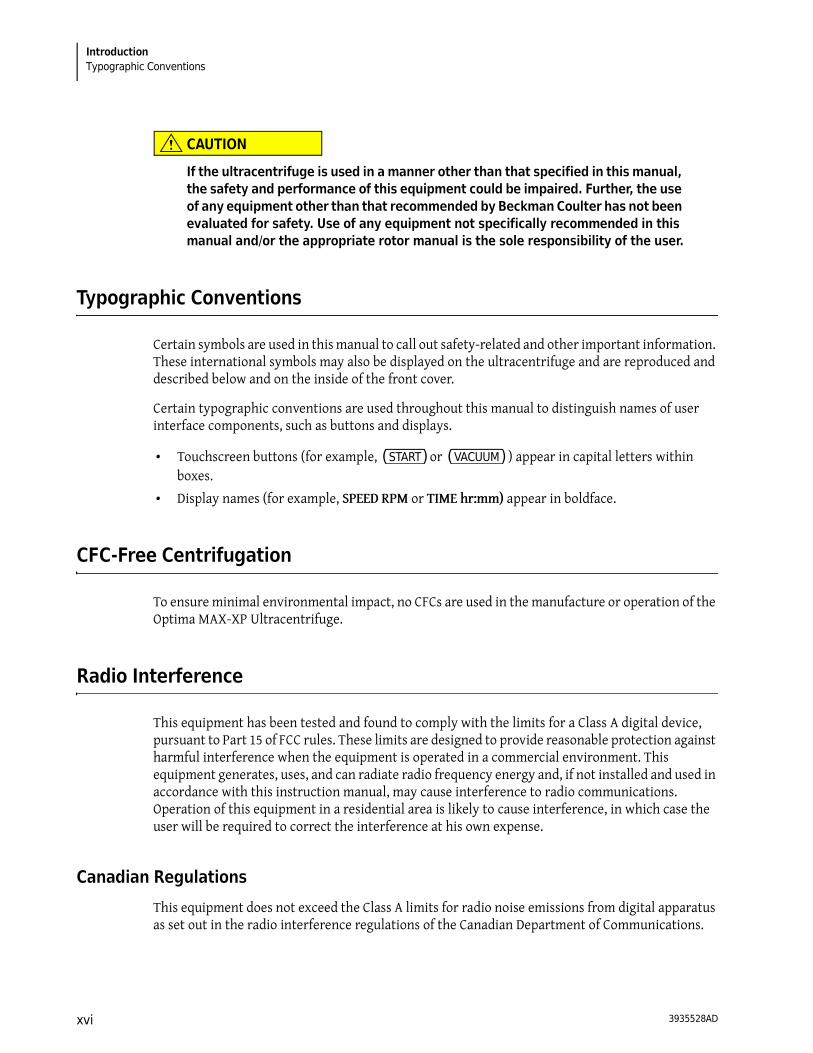
CAUTION
If the ultracentrifuge is used in a manner other than that specified in this manual, the safety and performance of this equipment could be impaired. Further, the use of any equipment other than that recommended by Beckman Coulter has not been evaluated for safety. Use of any equipment not specifically recommended in this manual and/or the appropriate rotor manual is the sole responsibility of the user.
Typographic Conventions
Certain symbols are used in this manual to call out safety-related and other important information. These international symbols may also be displayed on the ultracentrifuge and are reproduced and described below and on the inside of the front cover.
Certain typographic conventions are used throughout this manual to distinguish names of user interface components, such as buttons and displays.
• Touchscreen buttons (for example, (START) or (VACUUM) ) appear in capital letters within boxes.
• Display names (for example, SPEED RPM or TIME hr:mm) appear in boldface.
CFC-Free Centrifugation
To ensure minimal environmental impact, no CFCs are used in the manufacture or operation of the Optima MAX-XP Ultracentrifuge.
Radio Interference
This equipment has been tested and found to comply with the limits for a Class A digital device, pursuant to Part 15 of FCC rules. These limits are designed to provide reasonable protection against harmful interference when the equipment is operated in a commercial environment. This equipment generates, uses, and can radiate radio frequency energy and, if not installed and used in accordance with this instruction manual, may cause interference to radio communications. Operation of this equipment in a residential area is likely to cause interference, in which case the user will be required to correct the interference at his own expense.
Canadian Regulations
This equipment does not exceed the Class A limits for radio noise emissions from digital apparatus as set out in the radio interference regulations of the Canadian Department of Communications.
3935528ADxvi
IntroductionRecycling Label
Le présent appareil numérique n’émet pas de bruits radioélectriques dépassant les limites applicables aux appareils numériques de Classe A prescrites dans le reglement sur le brouillage radioelectrique édicté par le Ministère des Communications du Canada.
Recycling Label
This symbol is required in accordance with the Waste Electrical and Electronic Equipment (WEEE) Directive of the European Union. The presence of this marking on the product indicates:
1. The device was put on the European market after August 13, 2005 and
2. The device is not to be disposed of via the municipal waste collection system of any member state of the European Union.
It is very important that customers understand and follow all laws regarding the proper decontamination and safe disposal of electrical equipment. For Beckman Coulter products bearing this label, please contact your dealer or local Beckman Coulter office for details on the take-back program that will facilitate the proper collection, treatment, recovery, recycling, and safe disposal of the device.
NOTE On the instrument, the triangle background is yellow rather than gray.
A28219-AA
3935528AD xvii

IntroductionRecycling Label
3935528ADxviii

CHAPTER 1
Description
Description
The Optima MAX-XP microprocessor-controlled tabletop ultracentrifuge (see Figure 1.1) generates high centrifugal forces for a variety of applications. The ultracentrifuge design features a variable-frequency induction drive, thermoelectric temperature control system, self-purging vacuum system, rotor overspeed identification system, user login feature, program memory that contains multiple five-step programs, and a choice of acceleration and deceleration rates.
Manual and programmed operations are available from the integrated touchscreen interface.
• In manual operation, you enter the individual run parameters before beginning each run.
• In programmed operation, you can duplicate runs quickly and accurately by selecting previously entered programs and running them again.
Additionally, a pulse feature allows you to manually accelerate the rotor for sample preparation.
Figure 1.1 The Optima MAX-XP Ultracentrifuge
Rotor Chamber
The steel chamber is coated with a chemical-resistant finish to resist corrosion. The rotor drive hub and speed sensors are visible in the bottom of the chamber.
3935528AD 1-1

DescriptionTemperature Sensing and Control
Vacuum System
A diffusion pump, in series with a mechanical vacuum pump, reduces chamber pressure to below 10 microns (1.34 Pa). The vacuum system turns on when you press the (VACUUM) button on the touchscreen, or when you start a run. When the vacuum system is turned on, a self-purging system continuously removes moisture from the vacuum system.
There are two ways to start the vacuum system (there must be power to the ultracentrifuge):
• To start pumping air out of the chamber manually, press the (VACUUM) button. The chamber door locks and the vacuum system starts.
• To start the vacuum system for a run, place the rotor in the chamber, close the door, and press the (START) button. The door locks, the rotor starts spinning, and the vacuum system starts.
The (VACUUM) button on the touchscreen interface turns green when the vacuum system is activated. The button displays the vacuum level in microns.
To release the vacuum system, press the (VACUUM) button after the rotor has come to a complete stop. This unlocks the door and turns off the vacuum system, including the mechanical and diffusion pumps.
Temperature Sensing and Control
The solid-state thermoelectric temperature control system uses only forced air—no coolant is required. With the power on, the temperature control system is activated when the door is closed. and the vacuum system is turned on. Run temperature can be set between 0 and 40°C.
A sensor in the rotor chamber continuously monitors chamber temperature. The microprocessor calculates the required chamber temperature to maintain the selected rotor temperature. Peak-to-peak fluctuations of rotor temperature (after reaching thermoequilibrium) will be within 0.1°C (see Figure 1.2).
Figure 1.2 Temperature Control Diagram
Time
Set Temperature+2°
-2°
Actual rotor temperature
0.1° (peak-to-peak fluctuation)
°C
3935528AD1-2
DescriptionDrive 1
Drive
The air-cooled, direct-drive induction motor is frequency controlled, with no gears or brushes. In addition, the drive does not require an oil vacuum seal or external oil reservoir. It is externally cooled by forced air and internally cooled by oil. The drive delivers ultra-smooth, quiet performance.
Controls and Indicators
Power Switch
The power switch, located on the right-hand side of the ultracentrifuge, controls electrical power to the ultracentrifuge. When the instrument is first turned on, the display will be blank for approximately 10 seconds until the user interface is launched. The power switch is also a circuit breaker that will trip to cut off power in the event of a power overload. The power switch must be turned on before the chamber door can be opened. In the event of a power failure, you can retrieve your sample manually. For more information, see Retrieving Your Sample in Case of Power Failure in CHAPTER 4, Troubleshooting.
Touchscreen Interface
The operation of the ultracentrifuge is controlled via the touchscreen interface display, which comprises touch-sensitive display fields and buttons for entering and displaying run parameters and program information. When you press a button, additional screens may appear to allow you to enter or select more information. Figure 1.3 points out the elements of the touchscreen interface.
Use your fingertip to press the buttons on the touchscreen. A short beep sounds each time you press a button.
During operation (Run mode), the Speed, Time, and Temp display fields provide real-time status.
3935528AD 1-3

DescriptionControls and Indicators
Figure 1.3 Touchscreen Interface
The buttons and display fields on the Main screen are described briefly below. For complete information and instructions on using the touchscreen interface, see CHAPTER 3, Operation.
Table 1.1 Touchscreen interface item description
Item Number Item Description
1 Windshield
2 Screen instructions
3 Help button
4 Set values
5 Login Button
6 Buttons and display fields
7 Menu button
3935528AD1-4

DescriptionControls and Indicators 1
Touchscreen Element Description
Color-coded windshield
The windshield changes color to indicate the current state of the ultracentrifuge:
• Blue indicates Set-up mode. • Green indicates that a run (or a delayed run) is in progress (Run mode). • Red indicates a diagnostic or user alert. A message is displayed to provide
information and allow you to take the appropriate action.The center of the windshield displays instructions for entering parameters and other commands in each screen.
(MENU)
(BACK)
Press the (MENU) button in the upper left-hand corner of the screen to open the
menu. When you are working in other screens, the (MENU) button changes to
the (BACK) button to allow you to navigate back to the previous screen.
The menu options are:
• History - Displays a list of previous runs. • Accel/Decel - Displays a screen in which to select the acceleration and
deceleration rates. • Program - Displays a list of programmed runs and provides an interface from
which to set up new programs. • Admin - Opens the Administrator Options screen. If no user with
Administrator privileges is logged in, opens the User Login screen. • My Options - If no users are logged in, opens the User Login screen. If a user
is logged in, displays the Choose Button Type screen. • Pulse - Activates Pulse mode.
(HELP) Press the (HELP) button in the upper right-hand corner of the screen to display an online help window. The help text that appears applies to the information in the current screen.
(ROTOR) Press the (ROTOR) button to select a rotor. The currently selected rotor appears on the button.
(RPM/RCF) Press the (RPM/RCF) button to toggle between RPM and RCF.
RPM indicates rotor speed in revolutions per minute. RCF (relative centrifugal field) represents the ratio of the centrifugal acceleration at a specified radius and speed to the standard acceleration of gravity.
The currently selected mode appears in green above the horizontal line on the button.
(SPEED) Press the (SPEED) button to select the speed. The set speed appears above this button, which doubles as a display field for the actual run speed. The set speed and actual speed can be displayed in RPM or RCF.
When the speed is increasing (rotor acceleration), animated arrows in the display field point upward. When the speed is decreasing (rotor deceleration), the animated arrows point downward.
3935528AD 1-5
DescriptionSafety Features
Safety Features
The Optima MAX-XP ultracentrifuge has been designed and tested to operate safely indoors at altitudes up to 2 000 m (6 562 ft). Ultracentrifuge safety features are described below.
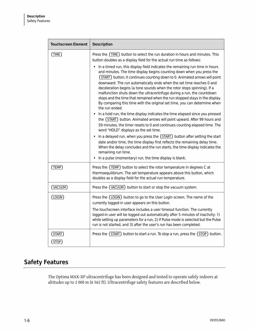
(TIME) Press the (TIME) button to select the run duration in hours and minutes. This button doubles as a display field for the actual run time as follows:
• In a timed run, this display field indicates the remaining run time in hours and minutes. The time display begins counting down when you press the (START) button; it continues counting down to 0. Animated arrows will point downward. The run automatically ends when the set time reaches 0 and deceleration begins (a tone sounds when the rotor stops spinning). If a malfunction shuts down the ultracentrifuge during a run, the countdown stops and the time that remained when the run stopped stays in the display. By comparing this time with the original set time, you can determine when the run ended.
• In a hold run, the time display indicates the time elapsed since you pressed the (START) button. Animated arrows will point upward. After 99 hours and 59 minutes, the timer resets to 0 and continues counting elapsed time. The word “HOLD” displays as the set time.
• In a delayed run, when you press the (START) button after setting the start date and/or time, the time display first reflects the remaining delay time. When the delay concludes and the run starts, the time display indicates the remaining run time.
• In a pulse (momentary) run, the time display is blank.
(TEMP) Press the (TEMP) button to select the rotor temperature in degrees C at thermoequilibrium. The set temperature appears above this button, which doubles as a display field for the actual run temperature.
(VACUUM) Press the (VACUUM) button to start or stop the vacuum system.
(LOGIN) Press the (LOGIN) button to go to the User Login screen. The name of the currently logged-in user appears on this button.
The touchscreen interface includes a user timeout function. The currently logged-in user will be logged out automatically after 5 minutes of inactivity: 1) while setting up parameters for a run, 2) if Pulse mode is selected but the Pulse run is not started, and 3) after the user’s run has been completed.
(START)
(STOP)
Press the (START) button to start a run. To stop a run, press the (STOP) button.
Touchscreen Element Description
3935528AD1-6
DescriptionName Rating Plate 1
Door
The steel chamber door has an electromechanical door-locking mechanism to prevent operator contact with a spinning rotor. To lock and unlock the door, press the (VACUUM) button on the touchscreen.
When there is a power failure, the door lock can be tripped manually for sample recovery. See CHAPTER 4, Troubleshooting.
Barrier Ring
A structural steel armor ring acts as the primary barrier, surrounded by a steel secondary barrier ring to provide full protection for the operator.
Imbalance Detector
An imbalance detector monitors the rotor during the run, causing automatic shutdown if rotor loads are severely out of balance. At low speeds, an incorrectly loaded rotor can cause an imbalance. Rotor instability can also occur if the ultracentrifuge is moved, or if it is not resting level on the work surface. See CHAPTER 4, Troubleshooting.
Overspeed and Rotor Identification System
The overspeed system, which includes magnetic speed sensors in the rotor chamber and magnets on the bottom of each rotor, continuously monitors the rotor during centrifugation. At 1 000 RPM, the system identifies the maximum permitted speed.
Name Rating Plate
A name rating plate is affixed to the rear of the ultracentrifuge. When contacting Beckman Coulter regarding your ultracentrifuge, always mention the serial number and model number. You can also view the serial number and other information by pressing the (HELP) button, then pressing the
(ABOUT) button in the Help screen.
Specifications
Only values with tolerances or limits are guaranteed data. Values without tolerances are informative data, without guarantee.
Speed
Set speed: 5 000 to 150 000 RPM in 1 000-RPM incrementsSpeed display: actual rotor speed in 100-RPM increments above 5 000 RPM and 10-RPM increments at speeds below 5 000 RPM
3935528AD 1-7

DescriptionSpecifications
Speed control: actual rotor speed, ±50 RPM of set speed
Time
Set time: to 99 hours 59 minutesTime display
Timed run: indicates run time remainingHold mode: indicates actual run timeProgrammed operation: indicates time remaining in step
Temperature
Set temperature: 0 to 40 C in 1 increments Temperature control (after equilibration): ±2 C of set temperature
Temperature display: actual rotor temperature in 0.1 increments Ambient temperature range: 15 to 35 C
Humidity restrictions: <75% (noncondensing)
Vacuum: below 10 microns (1.34 Pa)
Acceleration: 10 acceleration profiles—9 slow rates from 0 to 5 000 RPM followed by full acceleration to set speed; or maximum acceleration
Deceleration: 11 deceleration profiles—10 slow rates from 5 000 to 0 RPM, including coasting to a stop without brake; or full dynamic braking from set speed
Dimensions
Width: 73.9 cm (29.1 in.)Depth: 61.7 cm (24.3 in.)Height, front left: 34.5 cm (13.6 in.)Height, rear right: 39.4 cm (15.5 in.)
Weight: 105 kg (230 lb)
Ventilation clearances (sides and rear): 7.6 cm (3.0 in.)
Finishes
Touchscreen panel: coated polycarbonateTop surface: acrylic baking enamelOther surfaces: general purpose paint
Electrical supply: Class 1
3935528AD1-8
DescriptionAvailable Rotors 1
Electrical requirements
220/240 VAC~, 6 A, 50 Hz120 VAC~, 12 A, 50/60 Hz100 VAC~, 12 A, 50/60 Hz
Maximum heat dissipation into room under steady-state conditions: 2400 Btu/hr (0.7 kW)
Noise level 1 m in front of ultracentrifuge: <47 dB(A)
Installation category: II
Pollution degree: 2*
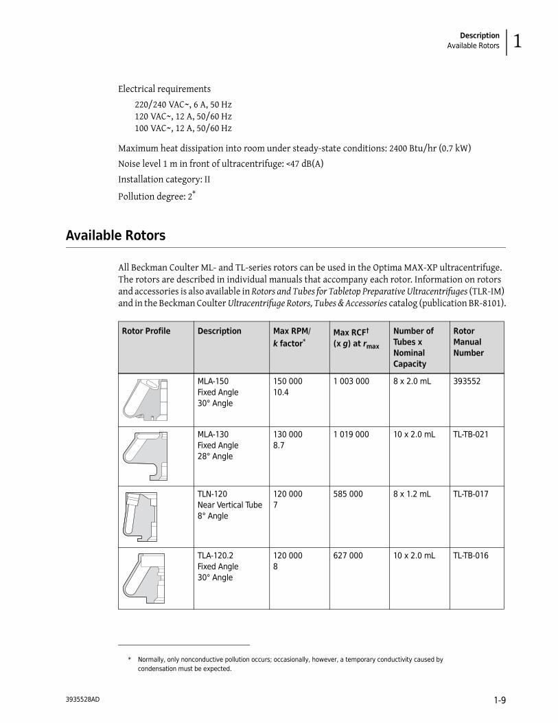
Available Rotors
All Beckman Coulter ML- and TL-series rotors can be used in the Optima MAX-XP ultracentrifuge. The rotors are described in individual manuals that accompany each rotor. Information on rotors and accessories is also available in Rotors and Tubes for Tabletop Preparative Ultracentrifuges (TLR-IM) and in the Beckman Coulter Ultracentrifuge Rotors, Tubes & Accessories catalog (publication BR-8101).
* Normally, only nonconductive pollution occurs; occasionally, however, a temporary conductivity caused by condensation must be expected.
Rotor Profile Description Max RPM/k factor*
Max RCF†
(x g) at rmax
Number of Tubes x Nominal Capacity
Rotor Manual Number
MLA-150Fixed Angle30° Angle
150 00010.4
1 003 000 8 x 2.0 mL 393552
MLA-130Fixed Angle28° Angle
130 0008.7
1 019 000 10 x 2.0 mL TL-TB-021
TLN-120Near Vertical Tube8° Angle
120 0007
585 000 8 x 1.2 mL TL-TB-017
TLA-120.2Fixed Angle30° Angle
120 0008
627 000 10 x 2.0 mL TL-TB-016
3935528AD 1-9

DescriptionAvailable Rotors
TLA-120.1Fixed Angle30° Angle
120 0008
627 000 14 x 0.5 mL TL-TB-015
TLA-110Fixed Angle28° Angle
110 00020
657 000 8 x 5.1 mL TL-TB-019
TLN-100Near Vertical Tube9° Angle
100 00014
450 000 8 x 3.9 mL TL-TB-013
TLA-100.4a
Fixed Angle28° Angle
100 00016
543 000 8 x 5.1 mL TL-TB-014
TLA-100.3Fixed Angle30° Angle
100 00014
543 000 6 x 3.5 mL TL-TB-011
TLA-100.2a
Fixed Angle30° Angle
100 00012
436 000 10 x 2.0 mL TL-TB-005
TLA-100.1a
Fixed Angle30° Angle
100 00012
436 000 12 x 0.5 mL TL-TB-004
TLA-100Fixed Angle30° Angle
100 0007
436 000 20 x 0.2 mL TL-TB-003
Rotor Profile Description Max RPM/k factor*
Max RCF†
(x g) at rmax
Number of Tubes x Nominal Capacity
Rotor Manual Number
3935528AD1-10

DescriptionAvailable Rotors 1
TLV-100Vertical Tube0° Angle
100 0009
400 000 8 x 2.0 mL TL-TB-007
MLN-80Near Vertical Tube9° Angle
80 00020
390 000 8 x 8.0 mL TL-TB-022
MLA-80Fixed Angle26° Angle
80 00029
444 000 8 x 8.0 mL TL-TB-024
MLA-55Fixed Angle35° Angle
55 00053
287 000 8 x 13.5 mL TL-TB-026
TLA-55Fixed Angle45° Angle
55 00066
186 000 12 x 1.5 mL TL-TB-020
TLS-55Swinging Bucket90° Angleb
55 00050
259 000 4 x 2.2 mL TL-TB-006
MLS-50Swinging Bucket90° Angleb
50 00071
268 000 4 x 5.0 mL TL-TB-023
TLA-45a
Fixed Angle45° Angle
45 00099
125 000 12 x 1.5 mL TL-TB-012
a. No longer manufactured.
b. At speed.
Rotor Profile Description Max RPM/k factor*
Max RCF†
(x g) at rmax
Number of Tubes x Nominal Capacity
Rotor Manual Number
3935528AD 1-11

DescriptionAvailable Rotors
* Maximum speeds are based on a solution density of 1.7 g/mL for all rotors, except the MLS-50, MLA-55, and MLA-80; solution density for these rotors is 1.2 g/mL. The k factors are listed for all Beckman Coulter rotors (using the largest-volume tube) as a measure of the rotor’s relative pelleting efficiency.
† Relative Centrifugal Field (RCF) is used to describe and compare the strength of the fields generated by different size rotors and different operating speeds. RCF is measured in units of multiples of the earth’s gravitational field, abbreviated (g). The formula for calculating the strength of a particular centrifugal field is:
where r is the radius in millimeters from the center of rotation to some point within the rotor; RPM is the speed of rotation in revolutions per minute.
RCF = 1.12r RPM 1000------------
⎝ ⎠⎛ ⎞ 2
3935528AD1-12
CHAPTER 2
Preinstallation Requirements
Introduction
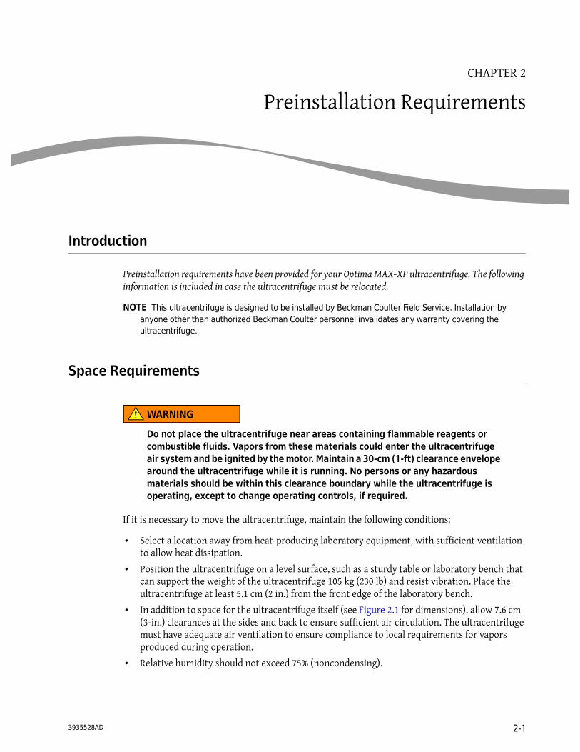
Preinstallation requirements have been provided for your Optima MAX-XP ultracentrifuge. The following information is included in case the ultracentrifuge must be relocated.
NOTE This ultracentrifuge is designed to be installed by Beckman Coulter Field Service. Installation by anyone other than authorized Beckman Coulter personnel invalidates any warranty covering the ultracentrifuge.
Space Requirements
WARNING
Do not place the ultracentrifuge near areas containing flammable reagents or combustible fluids. Vapors from these materials could enter the ultracentrifuge air system and be ignited by the motor. Maintain a 30-cm (1-ft) clearance envelope around the ultracentrifuge while it is running. No persons or any hazardous materials should be within this clearance boundary while the ultracentrifuge is operating, except to change operating controls, if required.
If it is necessary to move the ultracentrifuge, maintain the following conditions:
• Select a location away from heat-producing laboratory equipment, with sufficient ventilation to allow heat dissipation.
• Position the ultracentrifuge on a level surface, such as a sturdy table or laboratory bench that can support the weight of the ultracentrifuge 105 kg (230 lb) and resist vibration. Place the ultracentrifuge at least 5.1 cm (2 in.) from the front edge of the laboratory bench.
• In addition to space for the ultracentrifuge itself (see Figure 2.1 for dimensions), allow 7.6 cm (3-in.) clearances at the sides and back to ensure sufficient air circulation. The ultracentrifuge must have adequate air ventilation to ensure compliance to local requirements for vapors produced during operation.
• Relative humidity should not exceed 75% (noncondensing).
3935528AD 2-1

Preinstallation RequirementsElectrical Requirements
Figure 2.1 Dimensions of the Optima MAX-XP Ultracentrifuge
Electrical Requirements
To reduce the risk of electrical shock, this ultracentrifuge uses a 1.83-m (6-ft) three-wire electrical cord to be attached to the IEC 320/CEE-20 AC power connector at the rear of the ultracentrifuge and a plug to connect to earth-ground. (A plug that meets your local electrical and safety requirements was supplied with the ultracentrifuge. Contact your local Beckman Coulter office for specific information regarding local requirements.) To preserve this safety feature:
• Make sure that the matching wall outlet receptacle is properly wired and earth-grounded. Verify that the line voltage agrees with the voltage listed on the name rating plate affixed to the ultracentrifuge. Then plug in both ends of the ultracentrifuge power cord.
• Never use a three-to-two wire plug adapter.
• Never use a two-wire extension cord or a two-wire non-grounding type of multiple-outlet receptacle strip.
• If there is any question about voltage, have a qualified service person measure it under load while the drive is operating.
To ensure optimal safety, the ultracentrifuge should be wired to a remote emergency switch (preferably outside the room where the ultracentrifuge is housed, or adjacent to the exit from that room). In case of a malfunction, the ultracentrifuge can be disconnected from the main power source.
7.63.0
cmin.
7.63.0
73.929.1
61.724.3
39.415.5
34.513.6
Voltage ranges 220/240 VAC~, 6 A, 50 Hz120 VAC~, 12 A, 50/60 Hz100 VAC~, 12 A, 50/60 Hz
3935528AD2-2

CHAPTER 3
Operation
Introduction
This section contains manual and programmed operating procedures. A summary is provided at the start of this section for experienced users.
WARNING
Normal operation may involve the use of solutions and test samples that are pathogenic, toxic, or radioactive. Handle body fluids with care because they can transmit disease. No known test offers complete assurance that they are free of micro-organisms. Some of the most virulent—Hepatitis (B and C) and HIV (I-V) viruses, atypical mycobacteria, and certain systemic fungi—further emphasize the need for aerosol protection. Handle other infectious samples according to good laboratory procedures and methods to prevent spread of disease. Because spills may generate aerosols, observe proper safety precautions for aerosol containment. Do not run toxic, pathogenic, or radioactive materials in this ultracentrifuge without taking appropriate safety precautions. Biosafe containment should be used when Risk Group II materials (as identified in the World Health Organization Laboratory Biosafety Manual) are handled; materials of a higher group require more than one level of protection.
WARNING
Do not use the ultracentrifuge in the vicinity of flammable liquids or vapors, and do not run such materials in the ultracentrifuge. Do not lean on the ultracentrifuge or place items on it while it is operating.
Touchscreen Interface
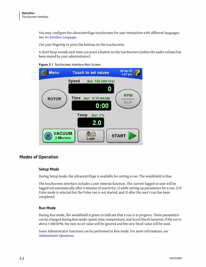
The touchscreen interface (see Figure 3.1) comprises menu options and touch-sensitive display fields and buttons for entering and displaying run parameters and program information. When you press a button or select a menu option, additional screens appear to allow you to enter or select more information.
3935528AD 3-1
OperationTouchscreen Interface
You may configure the ultracentrifuge touchscreen for user interaction with different languages. See Set Interface Language.
Use your fingertip to press the buttons on the touchscreen.
A short beep sounds each time you press a button on the touchscreen (unless the audio volume has been muted by your administrator).
Figure 3.1 Touchscreen Interface Main Screen
Modes of Operation
Setup Mode
During Setup mode, the ultracentrifuge is available for setting a run. The windshield is blue.
The touchscreen interface includes a user timeout function. The current logged-in user will be logged out automatically after 5 minutes of inactivity: 1) while setting up parameters for a run, 2) if Pulse mode is selected but the Pulse run is not started, and 3) after the user’s run has been completed.
Run Mode
During Run mode, the windshield is green to indicate that a run is in progress. These parameters can be changed during Run mode: speed, time, temperature, and Accel/Decel; however, if the run is above 5 000 RPM, the new Accel value will be ignored and the new Decel value will be used.
Some Administrator functions can be performed in Run mode. For more information, see Administrator Operations.
3935528AD3-2

OperationSummary of Optima MAX-XP Run Procedures 3
Diagnostics/User Messages
When a condition arises that requires operator attention, the windshield turns red. Press the windshield to open a dialog showing the diagnostic message. User messages communicate information about the ultracentrifuge or alert you to an abnormal condition. For more information, see CHAPTER 4, Troubleshooting.
Summary of Optima MAX-XP Run Procedures
This section provides a quick view of the steps for running the ultracentrifuge both manually and via a program. This is provided as a reference after you become are familiar with using the ultracentrifuge and the touchscreen interface. For detailed procedures that include images of the interface screens, see Manual Operation, Programmed Operation, and Pulse Run Operation.
For runs at other than room temperature, refrigerate or warm the rotor beforehand for fast equilibration. For non-room temperature runs, prepare the system as described under Ultracentrifuge Pre-Run Cooling or Warming.
Ultracentrifuge and Rotor Preparation
Prepare the rotor for centrifugation as described in the applicable rotor manual.
NOTE To achieve optimum ultracentrifuge performance, follow these instructions between runs: Leave the ultracentrifuge powered on, the door closed, and the vacuum turned on. You do not need to leave a rotor inside the chamber.
Installing the Rotor
The power must always be turned on before you can unlock and open the chamber door.
Action Result
1. Turn the power on. To end a run for any reason, do not turn the power off. Press the (STOP) button.
The touchscreen interface display turns on and is available.
2. Try opening the door. If the chamber is under vacuum and the door is locked, press the (VACUUM) button to vent the chamber and unlock the door.
The ultracentrifuge will accept this command only when the rotor is at rest. You can hear a slight hissing sound when the chamber vents.
3. After the chamber has been vented, use the door handle to slide the door open.
3935528AD 3-3

OperationSummary of Optima MAX-XP Run Procedures
Ultracentrifuge Pre-Run Cooling or Warming
Follow these steps to precool or warm the ultracentrifuge.
NOTE In addition to precooling or warming the ultracentrifuge, cool or warm the rotor outside the ultracentrifuge to the required temperature before the run for fast temperature equilibration.
Manual Run
This section is provided as a quick reference for executing a manual run. For detailed procedures of each step accompanied by screen shots of the touchscreen interface, see Manual Operation.
4. Install the rotor according to the directions in the rotor manual. Ensure that the rotor is seated on the drive hub.
NOTE TL-series rotors only—when installing a rotor on the drive hub, lock it in place by gently pressing the plunger in the rotor down until you hear a click. When you remove your finger, the plunger will remain depressed if it is properly engaged. If the plunger pops up, repeat the procedure, then try to gently lift the rotor to ensure that it is locked. No locking is required for ML-series rotors.
5. Close the chamber door. To keep the chamber clean and dry, leave the door closed whenever possible.
Action Result
1. Press the (TEMP) button on the Main screen. The Enter Run Temperature screen appears.
2. Enter the temperature, and press the (OK) button to accept.
The entered temperature becomes the set temperature that appears above the (TEMP) button on the Main screen.
3. Close the door.
4. Press the (VACUUM) button to turn the vacuum system on. Note that it is not necessary to use the (START) button.
Pre-run cooling or warming begins.
Action Result
1 POWER Turn the power on.
2 Install the rotor according to the applicable rotor manual, then close the chamber door.
3 (ROTOR) This step is optional. If you don’t want to select a rotor, go to Step 4.
Press this button, then choose the rotor (listed by type and serial number) from the rotor list.
4 (SPEED) Press this button, then enter the run speed (5 000 to 150 000 RPM).
3935528AD3-4

OperationManual Operation 3
Programmed Run
This section is provided as a quick reference for executing a programmed run. This procedure assumes that programmed runs have been created and saved. For detailed procedures of each step accompanied by screen shots of the touchscreen interface, see Programmed Operation.
Manual Operation
This section includes detailed procedures for entering run parameters for manual operation.
Preparing the Ultracentrifuge
In the first step of a manual run, install the rotor and perform any precooling or prewarming procedures that may be required. For more information and detailed steps, see Ultracentrifuge and Rotor Preparation.
5 (TIME) Press this button, then enter the run time (up to 99 hours, 59 minutes).
6 (TEMPERATURE) Press this button, then enter the required run temperature (0 to 40°C).
7 (MENU)Accel/Decel
This step is optional. To accept the default Accel/Decel rates of Max (maximum), go to Step 8.
Select the Accel/Decel menu option, and select the acceleration rate number, from Max (fastest) to 9 (slowest). Select the deceleration rate number, from Max (fastest) to 0 (coast).
You can skip this step and accept the default rates of Max (maximum).
8 (START) Press this button to start the run.
1 POWER Turn the POWER switch to ON.
2 Install the rotor according to the applicable rotor manual, then close the chamber door.
3 (MENU)Program
Program name
Select the Program menu option, then select a program from the list.
4 (OK) Press this button to load the program parameters.
5 (START) Press this button to start the run.
3935528AD 3-5
OperationManual Operation
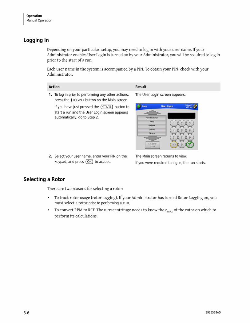
Logging In
Depending on your particular setup, you may need to log in with your user name. If your Administrator enables User Login is turned on by your Administrator, you will be required to log in prior to the start of a run.
Each user name in the system is accompanied by a PIN. To obtain your PIN, check with your Administrator.
Selecting a Rotor
There are two reasons for selecting a rotor:
• To track rotor usage (rotor logging). If your Administrator has turned Rotor Logging on, you must select a rotor prior to performing a run.
• To convert RPM to RCF. The ultracentrifuge needs to know the rmax of the rotor on which to perform its calculations.
Action Result
1. To log in prior to performing any other actions, press the (LOGIN) button on the Main screen.
If you have just pressed the (START) button to start a run and the User Login screen appears automatically, go to Step 2.
The User Login screen appears.
2. Select your user name, enter your PIN on the keypad, and press (OK) to accept.
The Main screen returns to view.
If you were required to log in, the run starts.
3935528AD3-6

OperationManual Operation 3
Action Result
1. On the Main screen, press the (ROTOR) button.
NOTE If you are starting a run without selecting a rotor and a message appears asking you to select a rotor, press (OK) in the
message box, then press the (ROTOR) button.
The Choose Rotor screen appears.
If necessary, use the large arrows to bring additional rotor names into view.
NOTE If No Rotor Selected is highlighted in this list, it means that no rotor is currently selected. If a rotor is selected and you want to remove it from your run parameters, select No Rotor Selected, or select another rotor.
2. Select the desired rotor, and press the (OK) button to accept.
The Main screen returns to view, and the selected rotor name and serial number appear on the (ROTOR) button.
If you were about to start a run and were required to select a rotor, the run starts automatically when the Main screen returns to view.
3. To convert RPM to RCF for the selected rotor, press the (RPM/RCF) button.
The conversion is calculated automatically, and the set RCF value appears above the Speed display. “RCF” displays in green above the horizontal line on the (RPM/RCF) button.
3935528AD 3-7
OperationManual Operation
Entering Run Speed
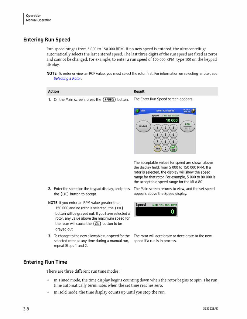
Run speed ranges from 5 000 to 150 000 RPM. If no new speed is entered, the ultracentrifuge automatically selects the last entered speed. The last three digits of the run speed are fixed as zeros and cannot be changed. For example, to enter a run speed of 100 000 RPM, type 100 on the keypad display.
NOTE To enter or view an RCF value, you must select the rotor first. For information on selecting a rotor, see Selecting a Rotor.
Entering Run Time
There are three different run time modes:
• In Timed mode, the time display begins counting down when the rotor begins to spin. The run time automatically terminates when the set time reaches zero.
• In Hold mode, the time display counts up until you stop the run.
Action Result
1. On the Main screen, press the (SPEED) button. The Enter Run Speed screen appears.
The acceptable values for speed are shown above the display field: from 5 000 to 150 000 RPM. If a rotor is selected, the display will show the speed range for that rotor. For example, 5 000 to 80 000 is the acceptable speed range for the MLA-80.
2. Enter the speed on the keypad display, and press the (OK) button to accept.
NOTE If you enter an RPM value greater than 150 000 and no rotor is selected, the (OK) button will be grayed out. If you have selected a rotor, any value above the maximum speed for the rotor will cause the (OK) button to be grayed out
The Main screen returns to view, and the set speed appears above the Speed display.
3. To change to the new allowable run speed for the selected rotor at any time during a manual run, repeat Steps 1 and 2.
The rotor will accelerate or decelerate to the new speed if a run is in process.
3935528AD3-8
OperationManual Operation 3
• In Delayed run mode, the time display first shows the remaining delay time. When the delay has concluded, the run starts and the time display counts down as in Timed mode.
Timed Mode
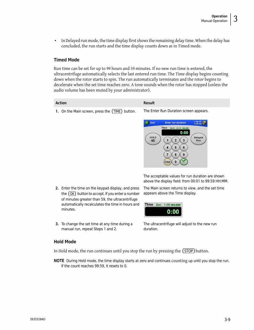
Run time can be set for up to 99 hours and 59 minutes. If no new run time is entered, the ultracentrifuge automatically selects the last entered run time. The Time display begins counting down when the rotor starts to spin. The run automatically terminates and the rotor begins to decelerate when the set time reaches zero. A tone sounds when the rotor has stopped (unless the audio volume has been muted by your administrator).
Hold Mode
In Hold mode, the run continues until you stop the run by pressing the (STOP) button.
NOTE During Hold mode, the time display starts at zero and continues counting up until you stop the run. If the count reaches 99:59, it resets to 0.
Action Result
1. On the Main screen, press the (TIME) button. The Enter Run Duration screen appears.
The acceptable values for run duration are shown above the display field: from 00:01 to 99:59 HH:MM.
2. Enter the time on the keypad display, and press the (OK) button to accept. If you enter a number of minutes greater than 59, the ultracentrifuge automatically recalculates the time in hours and minutes.
The Main screen returns to view, and the set time appears above the Time display.
3. To change the set time at any time during a manual run, repeat Steps 1 and 2.
The ultracentrifuge will adjust to the new run duration.
3935528AD 3-9

OperationManual Operation
Setting Up a Delayed Run
You can set up a run that starts or stops in the future.
Action Result
1. On the Main screen, press the (TIME) button. The Enter Run Duration screen appears.
The acceptable values for run duration are shown above the display field: from 00:01 to 99:59 HH:MM.
2. Press the (HOLD) button. The (HOLD) button turns green, and the word HOLD appears in the Time display field.
3. Press the (OK) button. The Main screen returns to view, and Hold mode is indicated above the Time display.
4. To cancel Hold mode, repeat Steps 1–3. The (HOLD) button turns gray in the Enter Run Duration screen. HOLD disappears from above the Time Display on the Main screen.
3935528AD3-10

OperationManual Operation 3
Action Result
1. On the Main screen, press the (TIME) button. The Enter Run Duration screen appears.
2. Enter the run duration, and press the (DELAYED RUN) button.
The Set Run Delay screen appears. The current date and time display in the fields.
3. To set a delayed run to start on a particular date and/or time, press the (START AT) button. To set a delayed run to stop on a particular date and/or time, press the (STOP AT) button.
NOTE If you set up a run to stop at a particular time, the starting time will be calculated automatically by the ultracentrifuge.
The Date and Time fields become active so you can change them.
4. Press the large arrows until you reach the desired date and time.To change the date or time rapidly, hold down the corresponding arrow.
3935528AD 3-11

OperationManual Operation
5. Press the (OK) button to accept. The Enter Run Duration screen returns to view; the (DELAYED RUN) button is green.
6. Press the (OK) button to accept. The Main screen returns to view, and the set duration of the delayed run appears above the Time display.
7. Press the (START) button.
If you are not logged in and User Login has been turned on by the Administrator, you are required to log in. For more information, see Logging In.If you are starting a run without selecting a rotor and a message appears asking you to select a rotor, press (OK) in the message box. You ‘ll need to select a rotor. For more information, see Selecting a Rotor.
The Main screen indicates that a delayed run is in progress. The time display first reflects the remaining delay time (as shown in the example below). When the delay concludes and the run starts, the time display indicates the remaining run time.
NOTE During a delayed run, you cannot change any parameters.
Action Result
3935528AD3-12
OperationManual Operation 3
Entering Run Temperature
Run temperature can be set from 0 to 40°C. If no new value is entered, the ultracentrifuge automatically uses the last entered temperature. If you clear the previous entry, 25°C is used as the operating temperature.
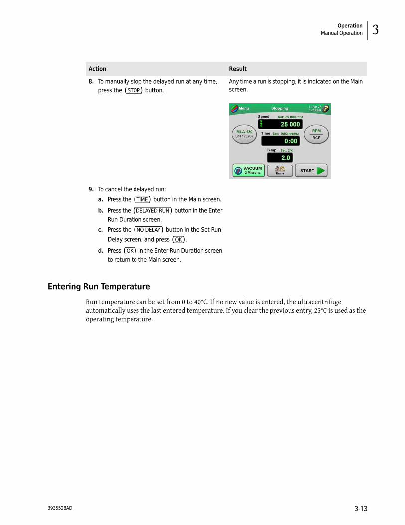
8. To manually stop the delayed run at any time, press the (STOP) button.
Any time a run is stopping, it is indicated on the Main screen.
9. To cancel the delayed run:
a. Press the (TIME) button in the Main screen.
b. Press the (DELAYED RUN) button in the Enter Run Duration screen.
c. Press the (NO DELAY) button in the Set Run
Delay screen, and press (OK) .
d. Press (OK) in the Enter Run Duration screen to return to the Main screen.
Action Result
3935528AD 3-13
OperationManual Operation
NOTE If the rotor temperature is not within 3°C above the set temperature for more than 40 minutes, a diagnostic message appears. If a run is in progress, the rotor will decelerate to a stop. See CHAPTER 4, Troubleshooting.
Entering Acceleration and Deceleration Rates
The ultracentrifuge provides ten acceleration rates and eleven deceleration rates to protect the gradient and sample-to-gradient interface. Table 3.1 lists these rates by their corresponding numbers on the touchscreen interface. Acceleration time is the time it takes a rotor to reach 5 000 RPM from rest. At 5 000 RPM, maximum acceleration takes over until the rotor reaches set speed. Deceleration time is the time it takes a rotor to decelerate from 5 000 to rest. From set speed to 5 000, the rotor decelerates with full dynamic braking.
If you use the default rates of maximum, the ultracentrifuge automatically accelerates and decelerates at maximum rate. When you change either the acceleration or deceleration rate, Accel and Decel buttons display appear on the Main screen showing the selected rates. You can then change the rates using these buttons as an alternative to using the Accel/Decel menu option.
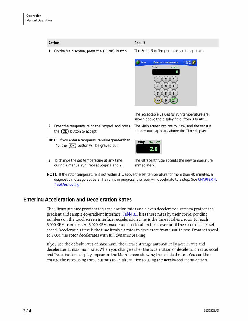
Action Result
1. On the Main screen, press the (TEMP) button. The Enter Run Temperature screen appears.
The acceptable values for run temperature are shown above the display field: from 0 to 40°C.
2. Enter the temperature on the keypad, and press the (OK) button to accept.
NOTE If you enter a temperature value greater than 40, the (OK) button will be grayed out.
The Main screen returns to view, and the set run temperature appears above the Time display.
3. To change the set temperature at any time during a manual run, repeat Steps 1 and 2.
The ultracentrifuge accepts the new temperature immediately.
3935528AD3-14

OperationManual Operation 3
Table 3.1 Acceleration and Deceleration Rates
Touchscreen Number
ACCEL Time from 0 to 5 000 RPM (MM:SS)
DECEL Time from 5 000 to 0 RPM (MM:SS)
Max 0:15a
a. Maximum rate. If no touchscreen number is selected, the rotor will accelerate and/or decelerate at the maximum rates.
0:15a
1 0:30 1:00
2 1:00 1:30
3 1:30 2:00
4 2:00 2:30
5 2:30 3:00
6 3:00 4:00
7 3:30 6:00
8 4:00 8:00
9 5:00 10:00
0 N/A Coasting stop from set speed without braking
Action Result
1. On the Main screen, press the (MENU) button in the upper left-hand corner.
The list of menu options appears.
2. Select Accel/Decel. The Select Accel/Decel Rates screen appears. The default value for both is Max (maximum speed).
3935528AD 3-15

OperationManual Operation
3. Press the desired rate(s) by pressing the appropriate number on the sliders.
The time duration for the rate you select is displayed in the fields on the right. If you select a deceleration rate of Coast, “Coast” appears, as shown in this example.
4. Press the (OK) button to accept. If either rate is set to anything other than Max, (ACCEL) and (DECEL) buttons appear on the Main screen showing the selected rates.
Action Result
3935528AD3-16

OperationManual Operation 3
Starting a Run
Action Result
1. On the Main screen, press the (START) button.
If you are not logged in and User Login has been turned on by the Administrator, you are required to log in. For more information, see Logging In.If you start a run without selecting a rotor and a message appears asking you to select a rotor, press (OK) in the message box. You’ll need to select a rotor. For more information, see Selecting a Rotor.
• The rotor starts spinning. • The vacuum system turns on unless it was
previously turned on. The (VACUUM) button turns green and the vacuum level is displayed.
• The touchscreen windshield turns green. • Animated arrows in the Speed, Time, and Temp
display fields represent the ultracentrifuge’s progress until the set values are reached.
• The (START) button changes to the (STOP) button.
The run will end automatically when the Time display counts down to zero, and a tone will sound.
NOTE Some features are not accessible during a run.
2. After the run has concluded, you can repeat the run using the same parameters. To do this, press the (START) button.
The set parameters will be used for the next run.
NOTE Keep the chamber door closed between runs.
3935528AD 3-17

OperationManual Operation
Stopping a Run
Recalling a Previous Run
Recalling a previous run serves two functions:
• To load the set information in as the parameters for a new run
• To view previous set and actual run information
Action Result
1. If you want to stop a run manually, press the (STOP) button on the Main screen.
Any time a run is stopping, it is indicated on the Main screen.
2. When the run stops and the time reaches 0, you can press the (VACUUM) button to turn off the vacuum system and vent the vacuum.
The chamber door unlocks so you can open it and remove your sample.
3935528AD3-18

OperationManual Operation 3
Action Result
1. On the Main screen, press the (MENU) button. The list of menu options appears.
2. Select History. A list of previous runs is displayed.
3. If necessary, use the arrows to bring additional runs into view. Select the desired run from the list.
4. To use the selected run, press the (OK) button. The parameters for the selected run are loaded into the ultracentrifuge and will appear on the Main screen.
3935528AD 3-19
OperationManual Operation
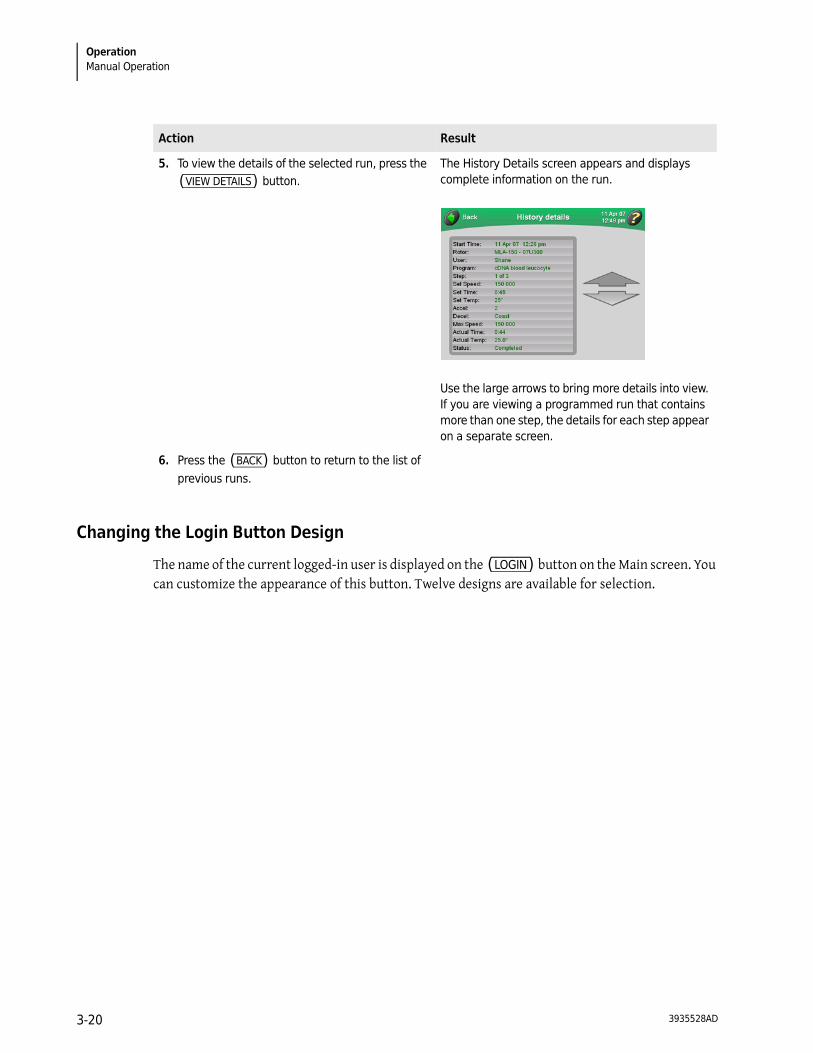
Changing the Login Button Design
The name of the current logged-in user is displayed on the (LOGIN) button on the Main screen. You can customize the appearance of this button. Twelve designs are available for selection.
5. To view the details of the selected run, press the (VIEW DETAILS) button.
The History Details screen appears and displays complete information on the run.
Use the large arrows to bring more details into view. If you are viewing a programmed run that contains more than one step, the details for each step appear on a separate screen.
6. Press the (BACK) button to return to the list of previous runs.
Action Result
3935528AD3-20
OperationProgrammed Operation 3
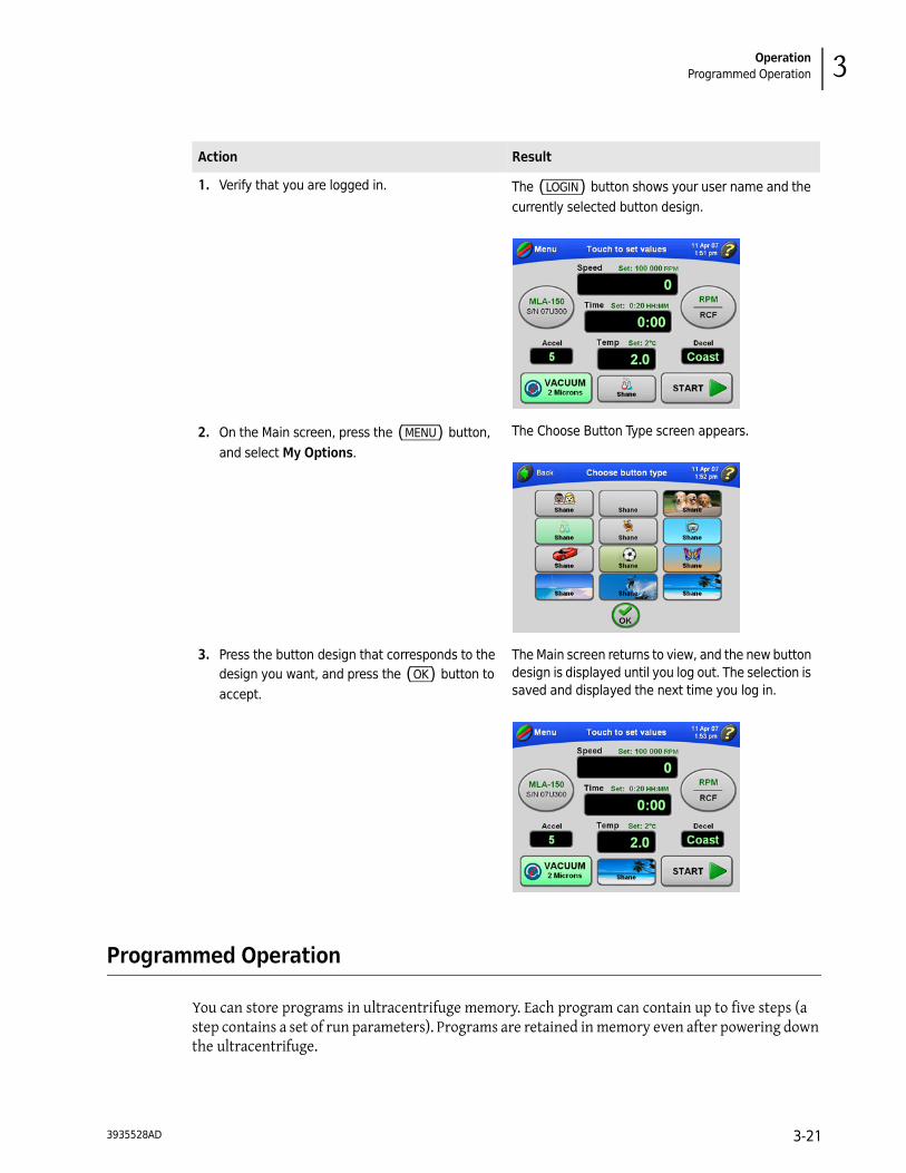
Programmed Operation
You can store programs in ultracentrifuge memory. Each program can contain up to five steps (a step contains a set of run parameters). Programs are retained in memory even after powering down the ultracentrifuge.
Action Result
1. Verify that you are logged in. The (LOGIN) button shows your user name and the currently selected button design.
2. On the Main screen, press the (MENU) button, and select My Options.
The Choose Button Type screen appears.
3. Press the button design that corresponds to the design you want, and press the (OK) button to accept.
The Main screen returns to view, and the new button design is displayed until you log out. The selection is saved and displayed the next time you log in.
3935528AD 3-21

OperationProgrammed Operation
Creating a New Program
Action Result
1. In the Main screen, press the (MENU) button. The list of menu options appears.
2. Select Program. The Select Program screen appears. If no programs have been created and saved, the screen will be blank.
3. Press the (NEW PROGRAM) button. The Program Summary screen appears.
3935528AD3-22
OperationProgrammed Operation 3
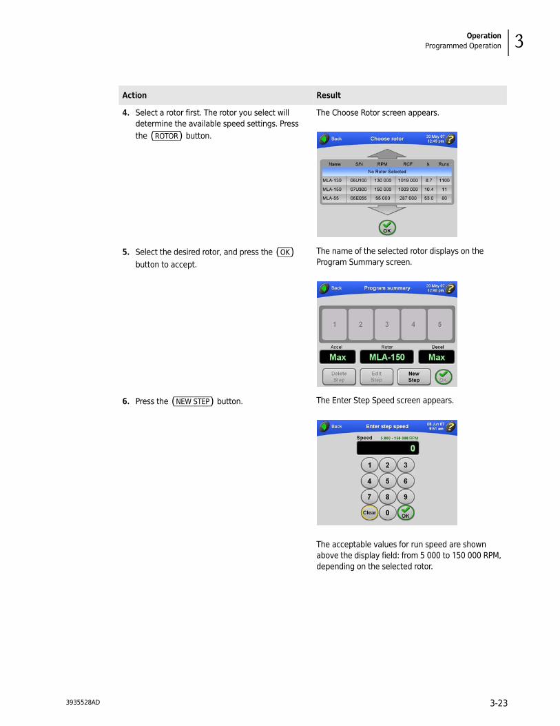
4. Select a rotor first. The rotor you select will determine the available speed settings. Press the (ROTOR) button.
The Choose Rotor screen appears.
5. Select the desired rotor, and press the (OK) button to accept.
The name of the selected rotor displays on the Program Summary screen.
6. Press the (NEW STEP) button. The Enter Step Speed screen appears.
The acceptable values for run speed are shown above the display field: from 5 000 to 150 000 RPM, depending on the selected rotor.
Action Result
3935528AD 3-23
OperationProgrammed Operation
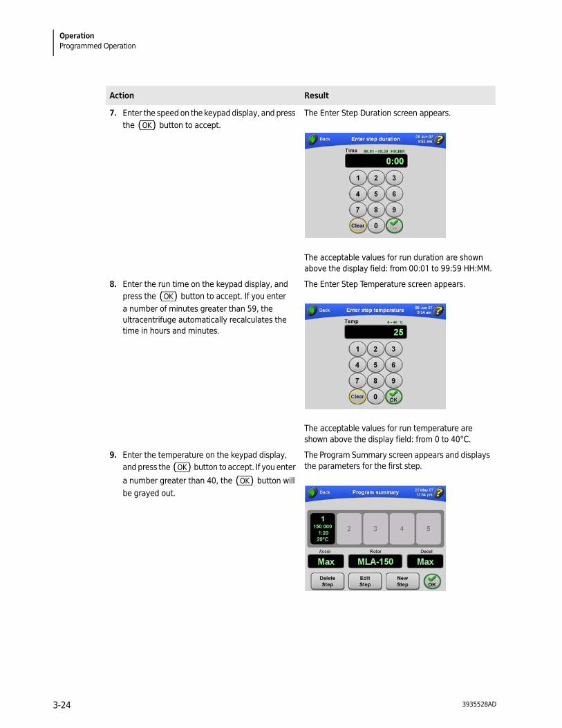
7. Enter the speed on the keypad display, and press the (OK) button to accept.
The Enter Step Duration screen appears.
The acceptable values for run duration are shown above the display field: from 00:01 to 99:59 HH:MM.
8. Enter the run time on the keypad display, and press the (OK) button to accept. If you enter a number of minutes greater than 59, the ultracentrifuge automatically recalculates the time in hours and minutes.
The Enter Step Temperature screen appears.
The acceptable values for run temperature are shown above the display field: from 0 to 40°C.
9. Enter the temperature on the keypad display, and press the (OK) button to accept. If you enter
a number greater than 40, the (OK) button will be grayed out.
The Program Summary screen appears and displays the parameters for the first step.
Action Result
3935528AD3-24

OperationProgrammed Operation 3
10.Repeat Steps 6–9 to enter the parameters for up to five steps for a complete run.
The Program Summary screen displays the parameters of the steps you’ve entered. The Accel value is for the first step in the program, and the Decel value is for the last step in the program.
After you enter five steps, the (NEW STEP) button is grayed out.
11. To change the acceleration/deceleration rates, press either the (ACCEL) or (DECEL) button. To use the maximum values for both rates, go to Step 12.
The Select Accel/Decel Rates screen appears.
Note that the default rates of “Max” (maximum) appear in the Time fields.
12.Select the desired rates by touching the corresponding numbers.
The approximate time duration for the rate you select is displayed on the right.
If you select a deceleration rate of coast, “COAST” appears in the Time field.
Action Result
3935528AD 3-25

OperationProgrammed Operation
13.Press the (OK) button to accept. The rates you select display on the Program Summary screen.
14.Press the (OK) button to accept. The Enter Program Name screen appears.
15.Type the name of the program using the keypad just as you would a keyboard.
Note that the (SHIFT) key is green to indicate that uppercase letters are the default. To enter lowercase letters, press the (SHIFT ) key.
Press (BACKSPACE) to erase entered characters one at a time.
To clear the entire entry, press (CLEAR) .
The name of the program appears at the top of the screen.
Action Result
3935528AD3-26
OperationProgrammed Operation 3
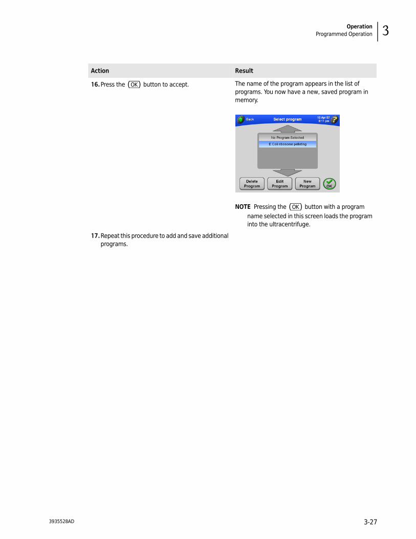
16.Press the (OK) button to accept. The name of the program appears in the list of programs. You now have a new, saved program in memory.
NOTE Pressing the (OK) button with a program name selected in this screen loads the program into the ultracentrifuge.
17.Repeat this procedure to add and save additional programs.
Action Result
3935528AD 3-27

OperationProgrammed Operation
Starting a Programmed Run
Action Result
1. In the Main screen, press the (MENU) button. The list of menu options appears.
2. Select Program. The Select Program screen appears.
NOTE If No Program Selected is highlighted in this list, it means that no saved program is currently selected.
3. Select the name of the program you want to run, and press the (OK) button.
The Main screen returns to view, and the name of the selected program appears in the windshield.
The run parameters for the first step appear above the display fields in the Main screen.
3935528AD3-28

OperationProgrammed Operation 3
Making Changes to a Program
You can modify any part of a program: the steps, the Accel/Decel rates, and the rotor.
4. Press the (START) button.
If you are not logged in and User Login has been turned on by the Administrator, you are required to log in. For more information, see Logging In.If you are starting a run without selecting a rotor and a message appears asking you to select a rotor, press (OK) in the message box. You’ll need to select a rotor. For more information, see Selecting a Rotor.
The Main screen reflects the start of the run. This screen updates continuously to reflect the progress of each step in the program.
5. To terminate a run for any reason, press the (STOP) button. When the rotor comes to a complete stop, a tone will sound.
The run will end automatically when the Time display counts down to zero for the last step in the program.
6. To exit from program mode:
a. Press the (MENU) button in the Main screen.
b. In the Select Program screen, select No Program Selected.
c. Press (OK) .
Alternatively, you can try changing a parameter such as speed, time, or temperature. A message appears asking you to confirm that you want to exit from program mode.
The Main screen returns to view so that you can enter parameters manually.
Action Result
3935528AD 3-29

OperationProgrammed Operation
Action Result
1. In the Main screen, press the (MENU) button. The list of menu options appears.
2. Select Program. The Select Program screen appears.
If necessary, use the arrows to bring additional program names into view.
3. Select the name of the program you want to modify.
The name of the program is highlighted, and the (EDIT PROGRAM) button becomes available.
3935528AD3-30

OperationProgrammed Operation 3
4. Press the (EDIT PROGRAM) button. The Program Summary screen displays the steps and other parameters of the selected program.
5. You can do any of the following: • Delete a step. Select the desired step and
press the (DELETE STEP) button.
• Edit a step. Selected the desired step and press the (EDIT STEP) button. For more information, see Creating a New Program.
• Add a step (if there are fewer than five steps in the program). Press the (NEW STEP) button. For more information, see Creating a New Program.
• Change the Accel/Decel rates. For more information, see Creating a New Program.
• Select a different rotor. For more information, see Creating a New Program.
Action Result
3935528AD 3-31

OperationProgrammed Operation
Deleting a Program
Action Result
1. In the Main screen, press the (MENU) button. The list of menu options appears.
2. Select Program. The Select Program screen appears.
3. Select the name of the program you want to delete. If necessary, use the arrows to bring additional program names into view.
The name of the program is highlighted, and the (DELETE PROGRAM) button becomes available.
4. To delete the program, press the (DELETE PROGRAM) button.
A confirmation message appears.
5. Press the (YES) button. The program is deleted and removed from the list of saved programs.
3935528AD3-32
OperationPulse Run Operation 3
Pulse Run Operation
Action Result
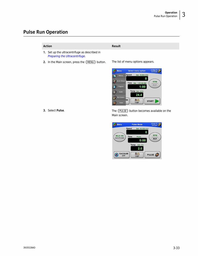
1. Set up the ultracentrifuge as described in Preparing the Ultracentrifuge.
2. In the Main screen, press the (MENU) button. The list of menu options appears.
3. Select Pulse. The (PULSE) button becomes available on the Main screen.
3935528AD 3-33
OperationRemote Operation
Remote Operation
The Optima MAX-XP ultracentrifuge can be operated from a remote computer using the software and hardware provided in Remote Control Kit 393395. For information on ordering this kit, contact Beckman Coulter.
Administrator Operations
This section describes the procedures performed by the Administrator. The Administrator performs system level operations, such as setting the date and time, adding and deleting users, turning User Login on and off, and turning Rotor Logging on and off. Any user with Administrator privileges has access to Administrator functions.
Accessing Administrator Options
NOTE You must have Administrator privileges to access these features. To find out of you have Administrator privileges, check with your system administrator.
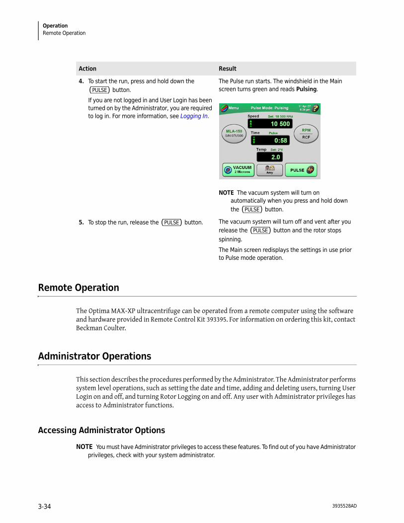
4. To start the run, press and hold down the (PULSE) button.
If you are not logged in and User Login has been turned on by the Administrator, you are required to log in. For more information, see Logging In.
The Pulse run starts. The windshield in the Main screen turns green and reads Pulsing.
NOTE The vacuum system will turn on automatically when you press and hold down the (PULSE) button.
5. To stop the run, release the (PULSE) button. The vacuum system will turn off and vent after you release the (PULSE) button and the rotor stops spinning.
The Main screen redisplays the settings in use prior to Pulse mode operation.
Action Result
3935528AD3-34
OperationAdministrator Operations 3
Set Interface Language
You may configure the ultracentrifuge touchscreen for user interaction with different languages. Follow the steps below to configure language settings.
Action Result
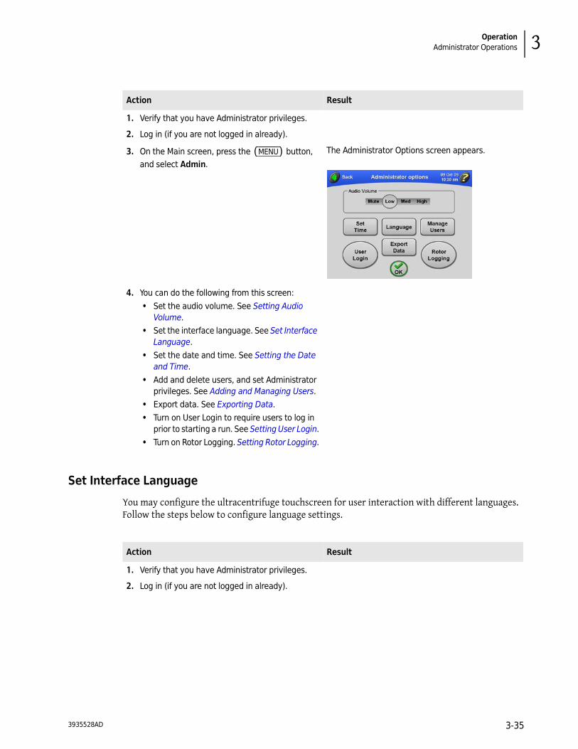
1. Verify that you have Administrator privileges.
2. Log in (if you are not logged in already).
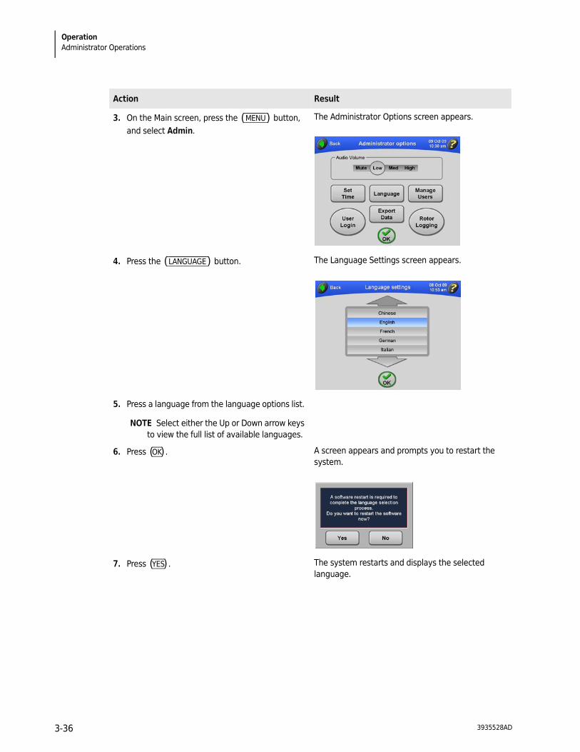
3. On the Main screen, press the (MENU) button, and select Admin.
The Administrator Options screen appears.
4. You can do the following from this screen: • Set the audio volume. See Setting Audio
Volume. • Set the interface language. See Set Interface
Language. • Set the date and time. See Setting the Date
and Time. • Add and delete users, and set Administrator
privileges. See Adding and Managing Users. • Export data. See Exporting Data. • Turn on User Login to require users to log in
prior to starting a run. See Setting User Login. • Turn on Rotor Logging. Setting Rotor Logging.
Action Result
1. Verify that you have Administrator privileges.
2. Log in (if you are not logged in already).
3935528AD 3-35
OperationAdministrator Operations
3. On the Main screen, press the (MENU) button, and select Admin.
The Administrator Options screen appears.
4. Press the (LANGUAGE) button. The Language Settings screen appears.
5. Press a language from the language options list.
NOTE Select either the Up or Down arrow keys to view the full list of available languages.
6. Press (OK) . A screen appears and prompts you to restart the system.
7. Press (YES) . The system restarts and displays the selected language.
Action Result
3935528AD3-36
3935528AD 3-37
OperationAdministrator Operations 3
Setting the Date and Time
Adding and Managing Users
Adding a User
Action Result
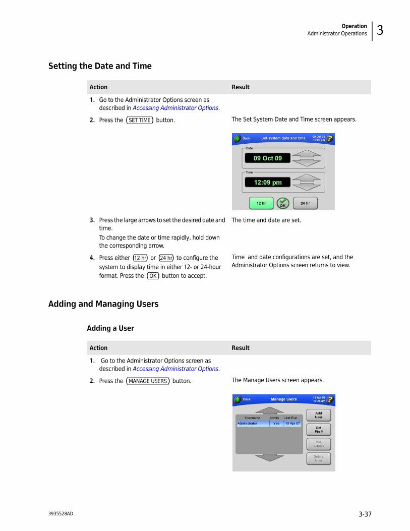
1. Go to the Administrator Options screen as described in Accessing Administrator Options.
2. Press the (SET TIME) button. The Set System Date and Time screen appears.
3. Press the large arrows to set the desired date and time. To change the date or time rapidly, hold down the corresponding arrow.
The time and date are set.
4. Press either (12 hr) or (24 hr) to configure the system to display time in either 12- or 24-hour format. Press the (OK) button to accept.
Time and date configurations are set, and the Administrator Options screen returns to view.
Action Result
1. Go to the Administrator Options screen as described in Accessing Administrator Options.
2. Press the (MANAGE USERS) button. The Manage Users screen appears.
OperationAdministrator Operations
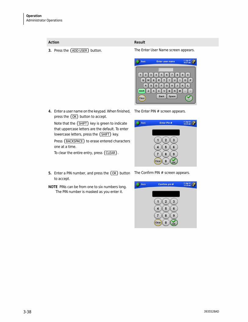
3. Press the (ADD USER) button. The Enter User Name screen appears.
4. Enter a user name on the keypad. When finished, press the (OK) button to accept.
Note that the (SHIFT) key is green to indicate that uppercase letters are the default. To enter lowercase letters, press the (SHIFT) key.
Press (BACKSPACE) to erase entered characters one at a time.
To clear the entire entry, press (CLEAR) .
The Enter PIN # screen appears.
5. Enter a PIN number, and press the (OK) button to accept.
NOTE PINs can be from one to six numbers long. The PIN number is masked as you enter it.
The Confirm PIN # screen appears.
Action Result
3935528AD3-38
OperationAdministrator Operations 3
Deleting a User
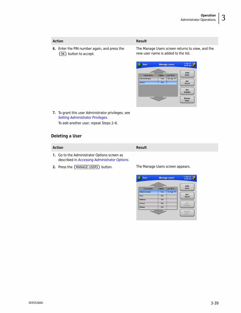
6. Enter the PIN number again, and press the (OK) button to accept.
The Manage Users screen returns to view, and the new user name is added to the list.
7. To grant this user Administrator privileges, see Setting Administrator Privileges.To add another user, repeat Steps 2–6.
Action Result
1. Go to the Administrator Options screen as described in Accessing Administrator Options.
2. Press the (MANAGE USERS) button. The Manage Users screen appears.
Action Result
3935528AD 3-39
OperationAdministrator Operations
Setting Administrator Privileges
In this procedure, you give other users Administrator privileges.
NOTE You must have Administrator privileges to perform this procedure.
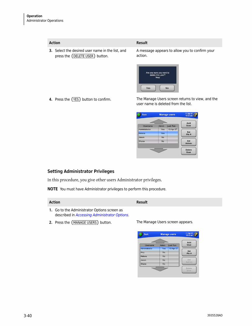
3. Select the desired user name in the list, and press the (DELETE USER) button.
A message appears to allow you to confirm your action.
4. Press the (YES) button to confirm. The Manage Users screen returns to view, and the user name is deleted from the list.
Action Result
1. Go to the Administrator Options screen as described in Accessing Administrator Options.
2. Press the (MANAGE USERS) button. The Manage Users screen appears.
Action Result
3935528AD3-40
OperationAdministrator Operations 3
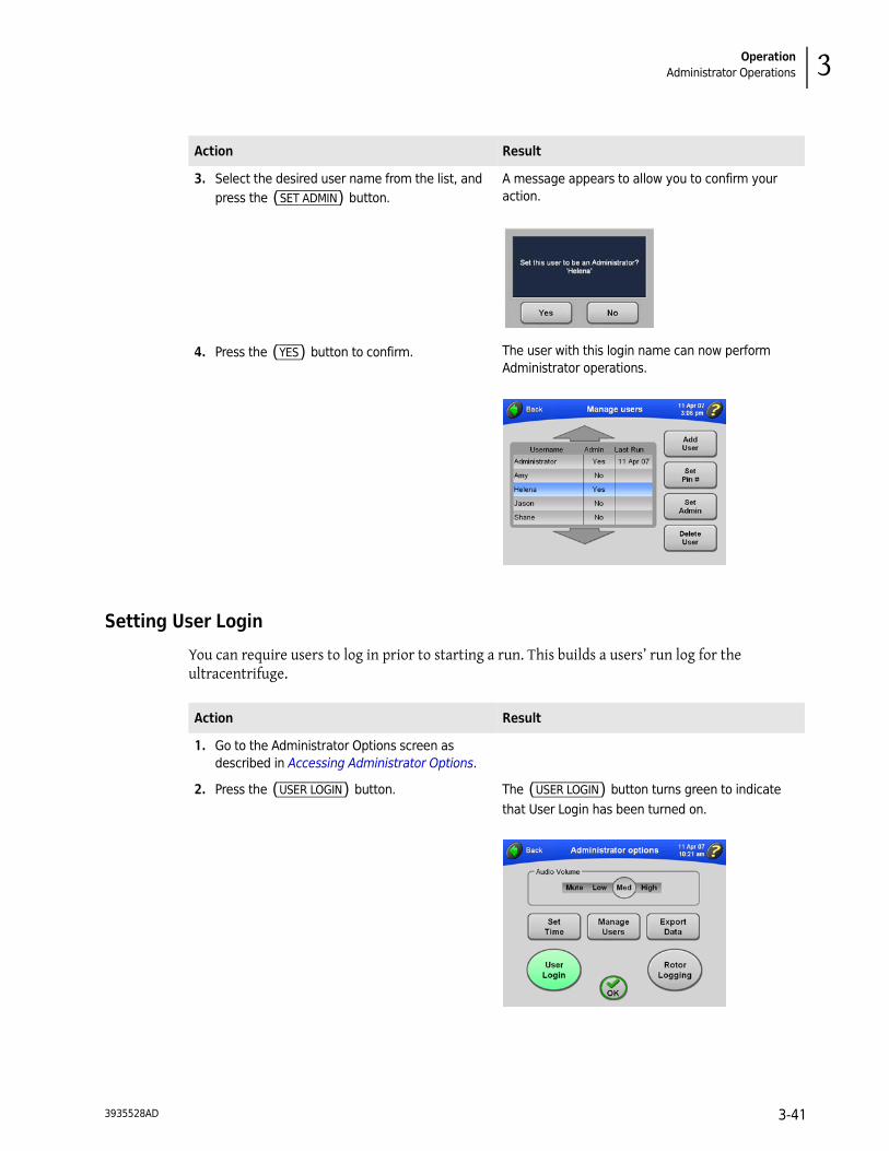
Setting User Login
You can require users to log in prior to starting a run. This builds a users’ run log for the ultracentrifuge.
3. Select the desired user name from the list, and press the (SET ADMIN) button.
A message appears to allow you to confirm your action.
4. Press the (YES) button to confirm. The user with this login name can now perform Administrator operations.
Action Result
Action Result
1. Go to the Administrator Options screen as described in Accessing Administrator Options.
2. Press the (USER LOGIN) button. The (USER LOGIN) button turns green to indicate that User Login has been turned on.
3935528AD 3-41

OperationAdministrator Operations
Setting Rotor Logging
When Rotor Logging is turned on, the user must select a rotor before starting a run. If a rotor is not selected, the user will be prompted to select the rotor in use.
Populating the Rotor Library
In this procedure, you develop a list of rotors that are available to users at your site.
NOTE You must have Administrator privileges to add rotors to and delete rotors from the rotor library.
3. Press the (OK) button to accept. When a user presses the (START) button to start a run, the user will be required to log in.
4. This feature is a toggle. To turn off User Login, repeat this procedure.
The (USER LOGIN) button turns gray in the Administrator Options screen to indicate that User Login is now off.
Action Result
Action Result
1. Go to the Administrator Options screen as described in Accessing Administrator Options.
2. Press the (ROTOR LOGGING) button. The (ROTOR LOGGING) button turns green to indicate that Rotor Logging has been turned on.
3. Press the (OK) button to accept. The ultracentrifuge will keep track of rotor usage.
Users will be required to select a rotor prior to starting a run (if no rotor is selected).
4. This feature is a toggle. To turn off Rotor Logging, repeat this procedure.
This toggles the (ROTOR LOGGING) button back to gray to indicate that Rotor Logging is now off.
3935528AD3-42

OperationAdministrator Operations 3
Action Result
1. On the Main screen, press the (ROTOR) button. The Choose Rotor screen appears.
2. Press the (ADD ROTOR) button. The Rotor Catalog screen appears.
The rotor catalog lists all rotors that can be used with the Optima MAX-XP. Select rotor names from the rotor catalog to develop the library of rotors available at your site.
If necessary, use the arrows to bring additional rotors into view.
3. Select the desired rotor, and press (OK) to accept.
The Enter Rotor Serial Number screen appears.
3935528AD 3-43

OperationAdministrator Operations
4. Enter the serial number for the selected rotor, and press (OK) to accept.
The Enter Rotor Run Count screen appears.
5. Enter the rotor run count, and press (OK) to accept.
NOTE The rotor run count is the number of runs a rotor has already accumulated.
The Choose Rotor screen returns to view, and the newly added rotor is listed in the rotor library.
6. To add another rotor, repeat Steps 2–5. The list of available rotors is available for selection by users of the ultracentrifuge.
7. To delete a rotor from the rotor library, select the rotor entry from the list, and press the (DELETE ROTOR) button.
A message appears to allow you to confirm your action.
8. Press the (YES) button to confirm. The rotor is deleted from the rotor library.
NOTE This action does not delete the rotor from the rotor catalog.
9. Press (BACK) to return to the Main screen.
Action Result
3935528AD3-44

OperationAdministrator Operations 3
Setting Audio Volume
Exporting Data
The ultracentrifuge automatically saves data associated with each run. You can export this run data for use in a spreadsheet program such as Microsoft Excel. The data, which consists of the set and actual parameters, user information, and rotor type and serial number, is saved in .csv format. To optimize instrument performance, we recommend exporting the data and then deleting data files from the system periodically.
Action Result
1. Go to the Administrator Options screen as described in Accessing Administrator Options.
2. Select the desired audio volume. The audio levels are: Mute, Low, Med, High.
3. Press the (OK) button to accept. The audio level adjusts to the new volume level, and the Main screen returns to view.
Action Result
1. Go to the Administrator Options screen as described in Accessing Administrator Options.
2. Press the (EXPORT DATA) button. You are prompted to insert a memory storage device into the USB slot on the right-hand side of the ultracentrifuge.
3. Insert the memory storage device into the USB port, and press the (EXPORT DATA) button.
When the data is exported successfully, a confirmation message is displayed.
3935528AD 3-45

OperationAdministrator Operations
4. To delete the data files you just exported, press the (DELETE DATA) button.
A message appears stating that all run history will be removed, and it asks you to confirm the operation.
5. Press the (YES) button. When the data is deleted, a confirmation message is displayed.
Action Result
3935528AD3-46

CHAPTER 4
Troubleshooting
Introduction
This section lists possible malfunctions, together with probable causes and corrective actions. Maintenance procedures are described in CHAPTER 5, Maintenance.
For any problems not covered here, contact Beckman Coulter Field Service (1-800-742-2345 in the United States; world-wide offices are listed on the outside back cover of this manual) for assistance.
NOTE It is your responsibility to decontaminate the ultracentrifuge, as well as any rotors and/or accessories, before requesting service by Beckman Coulter Field Service.
User Messages
Messages pop up on the touchscreen interface to communicate information about the ultracentrifuge or to alert you to conditions that require your attention. Dialog boxes with diagnostic messages contain a red border, as shown in the example in Figure 4.1. The possible diagnostic types are:
• CPU
• Power
• Speed
• Vacuum
• Temperature
• Drive
• Imbalance
• Door
NOTE The user should wait 10 seconds between turning instrument power off and then turning power on to clear an error condition.
3935528AD 4-1

TroubleshootingUser Messages
Figure 4.1 Example User Message on Touchscreen Interface
Table 4.1 User Message Chart
Message Definition/Result Possible Cause and Recommended Action
CPU Errors 101 through 113
Microprocessor malfunction or loss of program memory/Deceleration without brake
• If the microprocessor malfunction was caused by power failure, the error can be cleared by turning power off and back on; otherwise, no user action. (In case of program memory loss, the ultracentrifuge is still functional for manual operation.)
• Call Beckman Coulter Field Service.
Power Errors 201 and 202
Loss of power during centrifugation
A power outage has occurred during the run. If power is restored while the rotor is spinning, the run will resume. If the rotor came to a stop, however, restart the run.
Power Error 203 Loss of power during centrifugation/Deceleration without brake
A power outage has occurred during the run. Power was restored, but the run could not continue.
1. Turn the ultracentrifuge power off and back on.2. If the problem persists, call Beckman Coulter Field
Service.
Power Errors 204 through 207
Power supply error/Deceleration without brake
No user actions are recommended. Call Beckman Coulter Field Service.
Speed Error 301 No rotor installed/Deceleration with brake
1. Verify that the rotor is installed properly.2. If the problem persists, call Beckman Coulter Field
Service.
3935528AD4-2
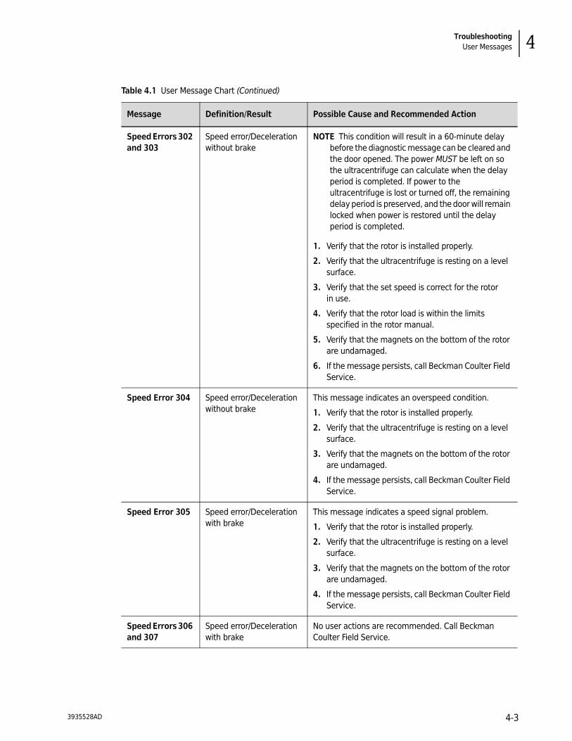
TroubleshootingUser Messages 4
Speed Errors 302 and 303
Speed error/Deceleration without brake
NOTE This condition will result in a 60-minute delay before the diagnostic message can be cleared and the door opened. The power MUST be left on so the ultracentrifuge can calculate when the delay period is completed. If power to the ultracentrifuge is lost or turned off, the remaining delay period is preserved, and the door will remain locked when power is restored until the delay period is completed.
1. Verify that the rotor is installed properly.
2. Verify that the ultracentrifuge is resting on a level surface.
3. Verify that the set speed is correct for the rotor in use.
4. Verify that the rotor load is within the limits specified in the rotor manual.
5. Verify that the magnets on the bottom of the rotor are undamaged.
6. If the message persists, call Beckman Coulter Field Service.
Speed Error 304 Speed error/Deceleration without brake
This message indicates an overspeed condition.
1. Verify that the rotor is installed properly.
2. Verify that the ultracentrifuge is resting on a level surface.
3. Verify that the magnets on the bottom of the rotor are undamaged.
4. If the message persists, call Beckman Coulter Field Service.
Speed Error 305 Speed error/Deceleration with brake
This message indicates a speed signal problem.
1. Verify that the rotor is installed properly.
2. Verify that the ultracentrifuge is resting on a level surface.
3. Verify that the magnets on the bottom of the rotor are undamaged.
4. If the message persists, call Beckman Coulter Field Service.
Speed Errors 306 and 307
Speed error/Deceleration with brake
No user actions are recommended. Call Beckman Coulter Field Service.
Table 4.1 User Message Chart (Continued)
Message Definition/Result Possible Cause and Recommended Action
3935528AD 4-3
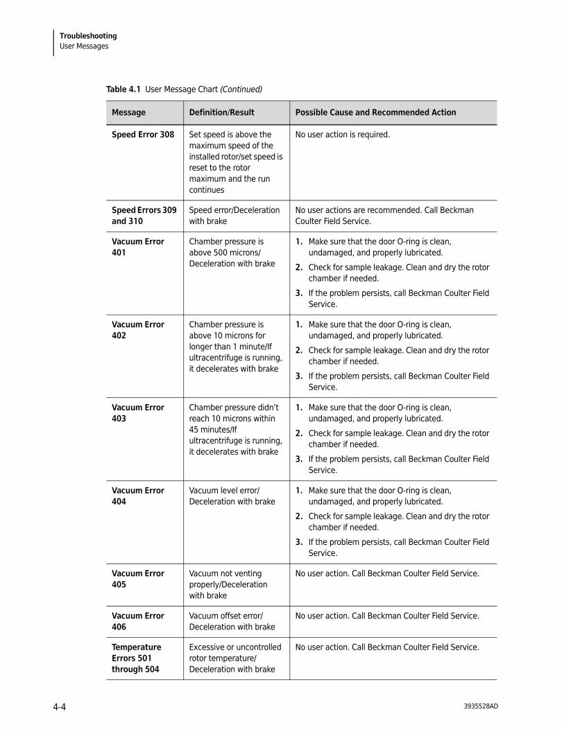
TroubleshootingUser Messages
Speed Error 308 Set speed is above the maximum speed of the installed rotor/set speed is reset to the rotor maximum and the run continues
No user action is required.
Speed Errors 309 and 310
Speed error/Deceleration with brake
No user actions are recommended. Call Beckman Coulter Field Service.
Vacuum Error 401
Chamber pressure is above 500 microns/Deceleration with brake
1. Make sure that the door O-ring is clean, undamaged, and properly lubricated.
2. Check for sample leakage. Clean and dry the rotor chamber if needed.
3. If the problem persists, call Beckman Coulter Field Service.
Vacuum Error 402
Chamber pressure is above 10 microns for longer than 1 minute/If ultracentrifuge is running, it decelerates with brake
1. Make sure that the door O-ring is clean, undamaged, and properly lubricated.
2. Check for sample leakage. Clean and dry the rotor chamber if needed.
3. If the problem persists, call Beckman Coulter Field Service.
Vacuum Error 403
Chamber pressure didn’t reach 10 microns within 45 minutes/If ultracentrifuge is running, it decelerates with brake
1. Make sure that the door O-ring is clean, undamaged, and properly lubricated.
2. Check for sample leakage. Clean and dry the rotor chamber if needed.
3. If the problem persists, call Beckman Coulter Field Service.
Vacuum Error 404
Vacuum level error/Deceleration with brake
1. Make sure that the door O-ring is clean, undamaged, and properly lubricated.
2. Check for sample leakage. Clean and dry the rotor chamber if needed.
3. If the problem persists, call Beckman Coulter Field Service.
Vacuum Error 405
Vacuum not venting properly/Deceleration with brake
No user action. Call Beckman Coulter Field Service.
Vacuum Error 406
Vacuum offset error/Deceleration with brake
No user action. Call Beckman Coulter Field Service.
Temperature Errors 501 through 504
Excessive or uncontrolled rotor temperature/Deceleration with brake
No user action. Call Beckman Coulter Field Service.
Table 4.1 User Message Chart (Continued)
Message Definition/Result Possible Cause and Recommended Action
3935528AD4-4
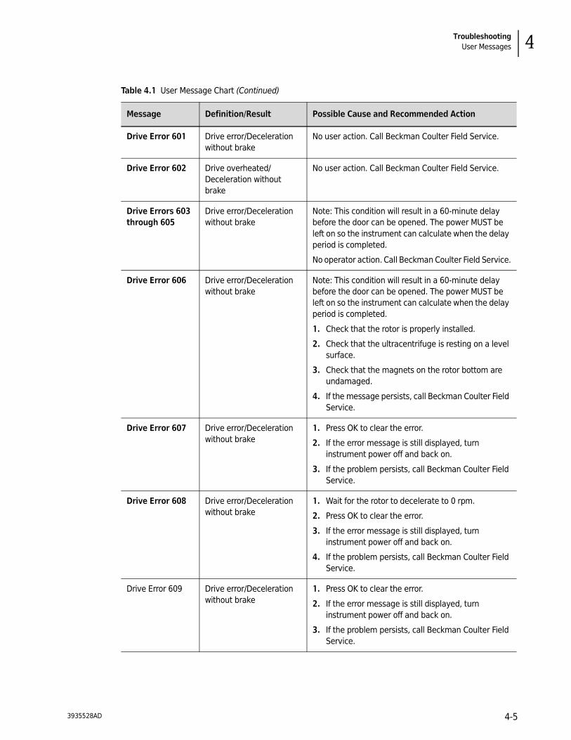
TroubleshootingUser Messages 4
Drive Error 601 Drive error/Deceleration without brake
No user action. Call Beckman Coulter Field Service.
Drive Error 602 Drive overheated/Deceleration without brake
No user action. Call Beckman Coulter Field Service.
Drive Errors 603 through 605
Drive error/Deceleration without brake
Note: This condition will result in a 60-minute delay before the door can be opened. The power MUST be left on so the instrument can calculate when the delay period is completed.
No operator action. Call Beckman Coulter Field Service.
Drive Error 606 Drive error/Deceleration without brake
Note: This condition will result in a 60-minute delay before the door can be opened. The power MUST be left on so the instrument can calculate when the delay period is completed.
1. Check that the rotor is properly installed.
2. Check that the ultracentrifuge is resting on a level surface.
3. Check that the magnets on the rotor bottom are undamaged.
4. If the message persists, call Beckman Coulter Field Service.
Drive Error 607 Drive error/Deceleration without brake
1. Press OK to clear the error.
2. If the error message is still displayed, turn instrument power off and back on.
3. If the problem persists, call Beckman Coulter Field Service.
Drive Error 608 Drive error/Deceleration without brake
1. Wait for the rotor to decelerate to 0 rpm.
2. Press OK to clear the error.
3. If the error message is still displayed, turn instrument power off and back on.
4. If the problem persists, call Beckman Coulter Field Service.
Drive Error 609 Drive error/Deceleration without brake
1. Press OK to clear the error.
2. If the error message is still displayed, turn instrument power off and back on.
3. If the problem persists, call Beckman Coulter Field Service.
Table 4.1 User Message Chart (Continued)
Message Definition/Result Possible Cause and Recommended Action
3935528AD 4-5

TroubleshootingRetrieving Your Sample in Case of Power Failure
Retrieving Your Sample in Case of Power Failure
If facility power fails only momentarily, the ultracentrifuge will resume operation (where it left off) when power is restored and the rotor will return to set speed. However, if the rotor came to a complete stop, you will need to restart the run when the power is restored. In either case, the POWER message will appear on the touchscreen interface to indicate that a power outage has occurred.
WARNING
Any maintenance procedure requiring removal of a panel exposes the operator to the possibility of electrical shock and/or mechanical injury. Therefore, turn the power OFF and disconnect the ultracentrifuge from the main power source, and refer such maintenance to service personnel.
In the event of an extended power failure, it may be necessary to trip the door-locking mechanism manually to remove the rotor and retrieve your sample.
Imbalance Error 701
Rotor imbalance detected/Deceleration with brake
1. Verify that the rotor is secured to the drive hub.
2. Check for proper balance and placement of tubes and/or buckets.
3. Restart the run.
4. If the problem persists, call Beckman Coulter Field Service.
Door Errors 801 through 803
Door open or unlocked/Deceleration with brake
1. Close the door properly and restart the run.
2. If the problem persists, call Beckman Coulter Field Service.
Table 4.1 User Message Chart (Continued)
Message Definition/Result Possible Cause and Recommended Action
3935528AD4-6
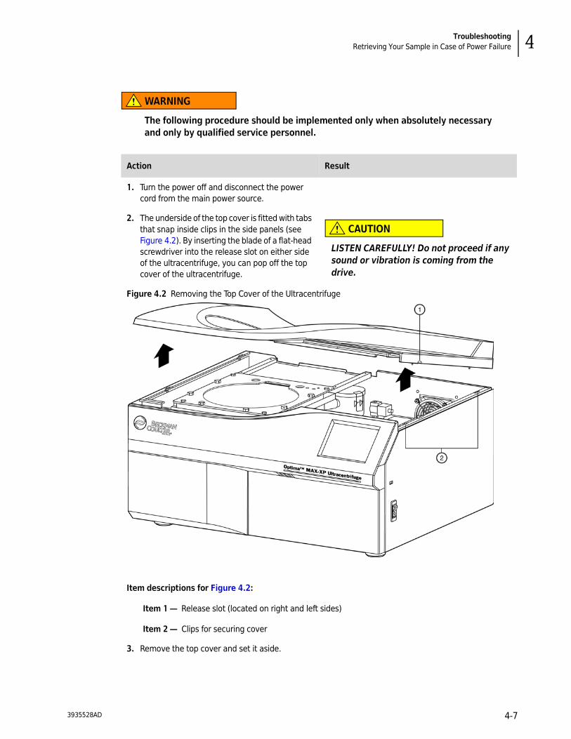
TroubleshootingRetrieving Your Sample in Case of Power Failure 4
WARNING
The following procedure should be implemented only when absolutely necessary and only by qualified service personnel.
Action Result
1. Turn the power off and disconnect the power cord from the main power source.
2. The underside of the top cover is fitted with tabs that snap inside clips in the side panels (see Figure 4.2). By inserting the blade of a flat-head screwdriver into the release slot on either side of the ultracentrifuge, you can pop off the top cover of the ultracentrifuge.
CAUTION
LISTEN CAREFULLY! Do not proceed if any sound or vibration is coming from the drive.
Figure 4.2 Removing the Top Cover of the Ultracentrifuge
Item descriptions for Figure 4.2:
Item 1 — Release slot (located on right and left sides)
Item 2 — Clips for securing cover
3. Remove the top cover and set it aside.
3935528AD 4-7
TroubleshootingRetrieving Your Sample in Case of Power Failure
4. Locate the vacuum solenoid valve (see Figure 4.3), and turn the screw clockwise until you hear air rush into the chamber.
The chamber vacuum is released. If you hear a whining noise, the rotor is still spinning. Close the valve and wait until the noise stops. When the sound of rushing air stops, the vacuum is vented.
5. Turn the screw counterclockwise to its closed position.
6. Locate the door lock system (see Figure 4.3), and push the spring-loaded pin down to unlock the door.
If the rotor is still spinning, close the door and wait. The drive is very quiet and may emit no audible sounds below 10 000 RPM.
WARNING
NEVER try to slow or stop the rotor by hand.
Action Result
3935528AD4-8

TroubleshootingRetrieving Your Sample in Case of Power Failure 4
Figure 4.3 Door Lock System
Item descriptions for Figure 4.3:
Item 1 — Screw
Item 2 — Spring loaded pin
Item 3 — Door lock system
Item 4 — Vacuum selenoid
7. Open the door and remove your sample.
8. To replace the top cover of the ultracentrifuge, line up the tabs with the openings on the side panels, and press down firmly until all sides and corners of the cover snap securely into place.
Action Result
3935528AD 4-9

TroubleshootingCircuit Breaker
Circuit Breaker
If the circuit breaker/power switch on the ultracentrifuge trips repeatedly, call Beckman Coulter Field Service. The circuit breaker/power switch is on the right-hand side of the ultracentrifuge.
3935528AD4-10

CHAPTER 5
Maintenance
This section contains care and maintenance procedures that should be performed regularly. For maintenance not covered in this manual, contact Beckman Coulter Field Service (1-800-742-2345 in the United States; worldwide offices are listed on the outside back cover of this manual) for assistance.
User messages and recommended actions are discussed in CHAPTER 4, Troubleshooting. Refer to the applicable rotor manual and Rotors and Tubes for instructions on the care of rotors and their accessories.
Ultracentrifuge Care
NOTE It is your responsibility to decontaminate the ultracentrifuge, as well as any rotors and/or accessories, before requesting service by Beckman Coulter Field Service.
WARNING
Any maintenance procedure requiring removal of a panel exposes the operator to the possibility of electrical shock and/or mechanical injury. Therefore, turn the power OFF and disconnect the ultracentrifuge from the main power source, and refer such maintenance to service personnel.
Vacuum System
For optimum performance of the vacuum system, keep the chamber O-ring (A31988) and area around the O-ring clean. (Ultracentrifuge O-rings have not been designed as bioseals for aerosol containment.) Wipe the area with a cloth dampened with a mild detergent such as Beckman Solution 555 (339555), diluted 10 to 1 with water.
Chamber O-Ring
Clean the O-ring every three or four months with alcohol and a lint-free cloth or tissue and coat it lightly, but evenly, with silicone vacuum grease (335148).
3935528AD 5-1

MaintenanceCleaning
Purging Moisture from the Vacuum Pump Oil
If a chamber pressure of 500 microns cannot be reached in about 3 minutes, there may be moisture in the vacuum pump oil. To purge this moisture:
1. Leave the ultracentrifuge turned on with the door closed and the vacuum pump turned on for about 3 hours or, if convenient, overnight.
2. Call Beckman Coulter Field Service to change the vacuum oil if it remains contaminated. (The ultracentrifuge will continue to display a VACUUM message after following the instruction in Step 1.)
Drive Hub
Check the drive hub and regularly wipe it clean as needed.
Air-Intake and Exhaust Louvers
Regularly verify that the air-intake and exhaust louvers are clean and unblocked. Use a vacuum cleaner or damp cloth to clean them.
Cleaning
NOTE Before using any cleaning or decontamination methods, except those recommended by the manufacturer, users should check with the manufacturer that the proposed method will not damage this equipment.
Ultracentrifuge Surfaces
Keep ultracentrifuge surfaces clean by wiping them with a cloth dampened with a mild detergent such as Beckman Solution 555 (diluted 10 to 1 with water). If salts or other corrosive materials are used, however, or if spillage occurs, wash all affected areas immediately. Do not allow corrosive materials to dry on the ultracentrifuge. (Be careful not to spill liquid on the ultracentrifuge where electrical or mechanical components could get damaged.)
3935528AD5-2

MaintenanceDecontamination 5
Touchscreen Display
To clean the touchscreen, use any standard glass cleaner (non-ammonia based). Do not spray cleaner or pour liquid on the screen. Always spray or apply the cleaner on an antistatic cloth first, then gently wipe the touchscreen.
Decontamination
If the ultracentrifuge and/or accessories are contaminated with radioactive or pathogenic solutions, follow appropriate decontamination procedures as determined by your laboratory safety officer. Refer to the chemical resistances list in Appendix A of Rotors and Tubes, or contact Beckman Coulter Field Service to ensure that the decontamination method does not damage any part of the ultracentrifuge (or accessories).
Sterilization and Disinfection
The top working surface is finished with acrylic baking enamel; the sides are finished with general purpose paint. Ethanol (70%)* may be used on both these surfaces. See Appendix A of Rotors and Tubes for more information on chemical resistance of ultracentrifuge and accessory materials.
While Beckman Coulter has tested these methods and found that they do not damage the ultracentrifuge, no guarantee of sterility or disinfection is expressed or implied. When sterilization or disinfection is a concern, consult your laboratory safety officer regarding proper methods to use.
Storage and Transportation
To ensure that the ultracentrifuge does not get damaged, contact Beckman Coulter Field Service for specific instructions and/or assistance in preparing the equipment for transport or long-term storage. Temperature and humidity requirements for storage should meet the environmental requirements described under Specifications in CHAPTER 1, Description.
Supply List
Contact Beckman Coulter Sales (1-800-742-2345 in the United States; worldwide offices are listed on the back cover of this manual) for information on ordering parts and supplies. A partial list of
* Flammability hazard. Do not use in or near operating ultracentrifuges.
3935528AD 5-3

MaintenanceSupply List
supplies is given below for your convenience. See the Beckman Coulter Ultracentrifuge Rotors, Tubes & Accessories catalog (BR-8101, available at www.beckmancoulter.com) for detailed information on ordering rotors, tubes, and accessories. Publications referenced in this manual can be obtained by calling 1-800-742-2345 in the United States or by contacting your local Beckman Coulter office.
Supplies
Optional Accessories
Spinkote lubricant (2 oz) 306812
Silicone vacuum grease (1 oz) 335148
Beckman Solution 555 (1 qt) 339555
HEPA filter kit 350799
Remote control kit 393395
3935528AD5-4

Warranty for the Optima MAX-XP Ultracentrifuge
Subject to the exceptions and upon the conditions specified below, Beckman Coulter agrees to correct, either by repair, or at its election by replacement, any defects of material or workmanship which develop within one (1) year after delivery of the Optima MAX-XP Ultracentrifuge (the product), to the original Buyer by Beckman Coulter or by an authorized representative provided that investigation and factory inspection by Beckman Coulter discloses that such defect developed under normal and proper use.
Some components and accessories by their nature are not intended to and will not function for as long as one (1) year. A complete list of such components or accessories is maintained at the factory and at each Beckman Coulter District Sales Office. The lists applicable to the products sold hereunder shall be deemed to be part of this warranty. If any such component or accessory fails to give reasonable service for a reasonable period of time, Beckman Coulter will repair or, at its election, replace such component or accessory. What constitutes either reasonable service and a reasonable period of time shall be determined solely by Beckman Coulter.
ReplacementAny product claimed to be defective must, if requested by Beckman Coulter, be returned to the factory, transportation charges prepaid, and will be returned to Buyer with the transportation charges collect unless the product is found to be defective, in which case Beckman Coulter will pay all transportation charges.
ConditionsBeckman Coulter makes no warranty concerning products or accessories not manufactured by it. In the event of failure of any such product or accessory, Beckman Coulter will give reasonable assistance to the Buyer in obtaining from the respective manufacturer whatever adjustment is reasonable in light of the manufacturer’s own warranty.
See the warranty that accompanies each rotor for ultracentrifuge rotor warranty information. Beckman Coulter shall be released from all obligations under all warranties, either expressed or implied, if the product(s) covered hereby are repaired or modified by persons other than its own authorized service personnel, unless such repair by others is made with the written consent of Beckman Coulter, or unless such repair in the sole opinion of Beckman Coulter is minor, or unless such modification is merely the installation of a new Beckman Coulter plug-in component for such product(s).
Special Drive WarrantyDuring the instrument warranty period (one year), there will be no charge for drive replacement if the drive unit is installed, serviced, and operated in accordance with the conditions listed below. During the second through tenth year of use the drive replacement costs, excluding labor and travel, will be covered by warranty if the drive unit is installed, serviced, and operated in accordance with the conditions listed below. This applies to units not under service contract.*
* For details of drive coverage with a service contact, contact your local Beckman Coulter service representative.
3935528AD Warranty-1

Conditions
1. The drive has been operated only within its rated speed and temperature ranges.
2. The drive unit has not been subjected to unequal loading, improper rotor installation, corrosion from material spilled onto the hub or accumulated in the chamber of the instrument.
3. The drive unit has not been disassembled, modified, or repaired, except by Beckman Coulter personnel.
4. The drive unit was installed by a Beckman Coulter Field Service representative.
5. The instrument in which the drive unit has been used and operated, and its associated rotors, were manufactured by Beckman Coulter and serviced only by Beckman Coulter Field Service representatives.
DisclaimerIT IS EXPRESSLY AGREED THAT THE ABOVE WARRANTY SHALL BE IN LIEU OF ALL WARRANTIES OF FITNESS AND OF THE WARRANTY OF MERCHANTABILITY AND THAT BECKMAN COULTER, INC. SHALL HAVE NO LIABILITY FOR SPECIAL OR CONSEQUENTIAL DAMAGES OF ANY KIND WHATSOEVER ARISING OUT OF THE MANUFACTURE, USE, SALE, HANDLING, REPAIR, MAINTENANCE, OR REPLACEMENT OF THE PRODUCT.
3935528AD Warranty-2

Warranty for the Optima MAX-XP Ultracentrifuge
3935528AD Warranty-3
© 2009 Beckman Coulter, Inc.All Rights Reserved
www.beckmancoulter.com
Beckman Coulter Worldwide Biomedical Research
Beckman Coulter, Inc.250 S. Kraemer Blvd.Brea, California 92821Sales and Service: 1-800-742-2345Internet: www.beckmancoulter.comFax: 1-800-643-4366

3935528AD 1-2


