Embed Size (px)
Citation preview

1
Technical Working Group Report to the
U.S.-Japan GPS Plenary
-----GPS-QZSS compatibility and interoperability-----
GPS-QZSS Technical Working Group
January 18, 2012

ii
Technical Working Group Report to the U.S.-Japan GPS Plenary
Table of Contents
1. Scope ................................................................................................................................... 1
2. GPS-QZSS TWG/EWG....................................................................................................... 2
2.1 Goal, Structure, Work plan ....................................................................................... 2
2.2 Meeting History ........................................................................................................... 4
3. Achievements of TWG/EWG ............................................................................................. 5
3.1. Interoperability between GPS and QZSS ................................................................. 5
3.1.1 Signal Structure and data format ................................................................................. 5
3.1.2 Time Offset ............................................................................................................... 8
3.1.3 Geodesy .................................................................................................................... 9
3.2 Radio Frequency Compatibility ................................................................................. 9
3.2.1 Coordination between N-SAT-HEO2/QZSS-1 and NAVSTAR GPS/NAVSTAR
GPS-IIRF ........................................................................................................................ 9
3.2.2 Coordination between N-SAT-HEO2/QZSS-1 and USRSR .............................. 10
3.2.3 Compatibility between GPS/QZSS and Indoor Messaging System (IMES) .... 11
3.3 Cooperation on QZSS Monitoring Stations (MS) .................................................... 12
3.4 Cooperation on Spectrum Protection for Radio Navigation Satellite Service
(RNSS) in ITU-R .............................................................................................................. 12
4. Evaluation Results for interoperability between GPS and QZSS ................................ 15
4.1. QZSS L1C signal ...................................................................................................... 15
4.2. Availability Improvement ........................................................................................ 18
4.3. Positioning Accuracy of GPS and QZSS ................................................................. 19
4.4. Confirmation of Compatibility between GPS and QZSS ....................................... 22
5. Conclusion ........................................................................................................................ 22
Appendix Acronyms ............................................................................................................ 23

1
1. Scope
The Global Positioning System (GPS)-Quasi-Zenith Satellite System
(QZSS) Technical Working Group (TWG) was established according to a
decision made by the 2nd
U.S.-Japan GPS Plenary meeting held on
October 16, 2002 in Tokyo, under the auspices of the 1998 U.S.-Japan
Joint Statement on Cooperation in the use of GPS. The purpose of the
TWG is to exchange information and share concepts in an effort to
achieve compatibility and technical interoperability between QZSS and
current and future configurations of GPS.
During the TWG discussions, both parties (U.S. and Japanese
Government representatives) identified the basic technical concepts for
GPS-QZSS compatibility and interoperability. The purpose of this
document is to provide results of investigations that demonstrate the
compatibility and interoperability between both systems and which were
adopted into the actual system design for the QZSS.
The first satellite of the QZSS, named as “Michibiki,” which means the
“Guiding light” or “Showing the way” in English, was launched
successfully on September 11, 2010. The Operations Team for Michibiki
has celebrated one year of successful operations on orbit. The recent
achievements of the technical demonstrations showing secure
compatibility and the effect of high interoperability between QZSS and
GPS are described in this report which was compiled as of the end of
November 2011.
Both parties identified the importance of continuous cooperation at
International Telecommunication Union (ITU) proceedings in order to
secure the safe and reliable operation for Radio Navigation Satellite
Service (RNSS) systems. This document describes collaborative activities
among the U.S., Japan and other RNSS providers and the results of those
activities at the ITU as well.

2
2. GPS-QZSS TWG/EWG
2.1 Goal, Structure, Work plan
The Quasi-Zenith Satellite System (QZSS) is a regional GPS
augmentation system which covers the East Asia and Oceania region. It
was designed to enhance GPS capability and performance by transmitting
navigation signals and augmentation messages with the same radio
frequency (RF) properties as GPS.
Compatibility between GPS and QZSS signals was an essential and
mandatory requirement for both systems. Additionally, high
interoperability between both systems was to be satisfied to secure
improvement of GPS capability without any huge modifications on current
GPS receiver’s design.
The goal of the TWG was defined as follows:
1) To secure the compatibility between both systems as a mandatory
requirement.
2) To maximize the interoperability between both systems for
obtaining better performance from combining use of GPS and QZSS
rather than GPS stand-alone usage.
3) To collaborate with each other to maintain allocated frequency
bands to RNSS in good condition without harmful interference with
other services with regard to ITU regulation.
4) To support establishment of the ground control segment of the
QZSS, especially Monitoring Stations in U.S.-owned facilities.
The TWG was established at the second U.S.-Japan GPS Plenary
meeting on October 16, 2002 in Tokyo under the auspices of the 1998
U.S.-Japan Joint Statement on Cooperation in the use of GPS. The QZSS
was a Research and Development program in Japan, and the related
ministries such as Ministry of Education, Culture, Sports, Science and
Technology (MEXT), Ministry of Internal Affairs and Communications
(MIC), Ministry of Economy Trade and Industry (METI) and Ministry of
Land, Infrastructure Transport and Tourism (MLIT) participated in the
TWG with their research institute members. On the U.S. side, the GPS
Joint Program Office (JPO) co-led the TWG, and United States Naval
Observatory (USNO), National Aeronautics and Space Administration
(NASA) and Federal Aviation Administration (FAA) with their technical

3
support contractors also participated in the TWG. The lead office for the
U.S. for the TWG has now transferred to the office of the Assistant
Secretary of the Air Force, Directorate of Space Programs, GPS Cell
(SAF/AQSL)
The first TWG meeting was held in Los Angeles, on December 4 to 5,
2002.
The Expert Working Group (EWG) was formed under the TWG
activity to discuss more detailed technical topics, inviting specialists from
the TWG members according to discussed topics based on mutual
agreement at the second TWG meeting on May 2 to 3, 2003. The first
EWG was held in Tokyo on January 20 to 21, 2004. Separate meetings
for two sub-groups: Timing; and Signal structure; were convened at the
first opportunity of the EWG, however, no separate sub-group meetings
have been conducted since then.
The work plan of the TWG is briefly summarized as follows:
1: Securing compatibility between GPS and QZSS
1-1: ITU operator-operator coordination between N-SAT-HEO2/QZSS-1
and NAVSTAR GPS/NAVSTAR GPS-IIRF
1-2: ITU operator-operator coordination between N-SAT-HEO2/QZSS-1
and USRSR
1-3: Compatibility study for Indoor Messaging System (IMES)
2: Maximizing interoperability between GPS and QZSS
2-1: QZSS GPS interoperable signal
2-2: Joint study for new L1C signal design
2-3: Timing
2-4: Geodetic reference
3: Collaboration in ITU information exchange and making joint strategy in
advance of ITU meeting.
3-1: ITU-R Recommendation describing RNSS technical characteristics
3-2: RNSS operating band protection
4: Cooperation for QZSS ground control segment
4-1: Feasibility study and site survey
4-2: Establishment agreement

4
2.2 Meeting History
As of January 18, 2012, nine meetings of TWG and twelve meetings of
the EWG have been held as shown in the Table 1.
Table 1: Meeting History of TWG and EWG
Meeting Date Place Note
#1 TWG December 4-5, 2002 Los Angeles
#2 TWG May 28-29, 2003 Los Angeles
#1 EWG January 20-21, 2004 Tokyo Signal structure
#2 EWG January 20, 2004 Tokyo Timing
#3 TWG January 21-22, 2004 Tokyo
#3 EWG November 19, 2004 Washington,
D.C.
#4 EWG/TWG July 19, 2005 Hawaii
#5 EWG January 24-25, 2006 Tokyo
#5 TWG January 26, 2006 Tokyo
#6 EWG August 4, 2006 Kauai, Hawaii
#7 EWG May 23, 2007 Washington,
D.C.
#6 TWG May 23, 2007 Washington,
D.C.
#8 EWG November 8, 2008 Tsukuba Space
Center
#9 EWG August 25, 2009 NOAA Weather
Forecasting
Station in Guam
Ribbon Cutting
Ceremony for
Guam MS
#10 EWG December 21, 2009 Tokyo
#7 TWG December 21, 2009 Tokyo
#11 EWG January 11-12, 2011 Tsukuba Space
Center
#8 TWG January 12, 2011 Tokyo
#12 EWG September 9, 2011 Tokyo Just after ICG #6
in Tokyo
#9 TWG January 17, 2012 Washington,
D.C.
Several technical video conferences and small group interim meetings
were also held between the 10th, 11
th and 12
th EWG meetings.

5
3. Achievements of TWG/EWG
3.1 Interoperability between GPS and QZSS
3.1.1 Signal Structure and data format
Technical concepts for GPS-QZSS interoperability were discussed and
investigated through the TWG. The outcome of the discussions was
introduced into the QZSS signal design and is defined in “Interface
Specification for QZSS (IS-QZSS)” which is available on the following
web site:
http://qz-vision.jaxa.jp/USE/is-qzss/index_e.html
3.1.1.1 Signal structure
The QZSS signal structure design for the L1, L2 and L5 bands was
introduced and discussed with respect to their compatibility and
interoperability with GPS signals. At the 5th
TWG and EWG meetings
which were held on January 24 to 26, 2006, both parties agreed that the
QZSS signals are fully compatible and interoperable with GPS, based on
the assumption documents at that time. The GPS L1C signal
specification, IS-GPS-800, was released as a draft document to the
public in April 2006. The QZSS signal specifications were released to
the public as the first draft documents in January 2007.
The following items were confirmed and agreed upon by both parties:
(1) Signal structure and characteristics
Through the entire orbit of each satellite, QZSS transmits positioning
signals on L1, L2, L5 and E6 bands.
Signals transmitted on L2 and L5 have the same structure and
characteristics as the GPS L2C and L5 signals, except for small
differences in the data messages, as described in a later section.
As for L1 band, QZSS transmits the following three signals
simultaneously:
1) L1C
2) L1 C/A
3) L1-SAIF

6
The L1C signal is a brand-new civil signal for GPS and will be
transmitted from Block III satellites, scheduled for first launch in 2014.
The L1C cooperative signal design effort has incorporated many U.S.
and Japanese L1C survey contributions, as well as joint U.S./Japan
participation in L1C Technical Meetings, which led to maximum
interoperability between the GPS and QZSS L1C signals. Both parties
agreed that they would like to develop cooperative L1C Interface
Specifications (IS) and to extend signal design cooperation to the L1
C/A, L2C and L5 signals at the 5th
TWG meeting. Based on discussion
at the 6th
EWG and a follow-on U.S.-Japan technical meeting, the U.S.
and Japan agreed that the control of L1C signal specifications,
IS-GPS-800 and IS-QZSS, would be implemented separately by both
parties. The EWG, TWG and close cooperation between U.S. and
Japanese experts through the GPS Interface Control Working Group
(ICWG) secured consistency between both documents in order to
maintain full interoperability with both systems.
Japanese experts determined that the minimum received signal powers
for all QZSS signals have been set to the same values as defined in
IS-GPS-200D, IS-GPS-705, and IS-GPS-800. Maximum powers for
all QZSS signals have been determined so that Radio Frequency
Compatibility with GPS is successfully achieved.
(2) Code assignment
The PRN assignment process was updated and the U.S. has created an
expanded set of PRN codes with good correlation properties. Japan
agreed to use the U.S. PRN codes and requested code sets for L1, L2 and
L5 QZSS signals, preferably numbers in a sequential order. Japan
submitted a PRN code application per the GPS Wing’s updated PRN
code assignment process after the 5th
TWG meeting. The official PRN
assignment process for QZSS PRN requests is complete. PRN number
193 is assigned to the first QZS satellite for the L1C, L1 C/A, L2C and
L5 signals. Also, PRN number 183 is assigned to the first QZS satellite
for the L1-SAIF signal. Finally, 9 additional PRN code sets for each
signal were granted to Japan for future QZS expansion.

7
The assignment tables for L1C, L1C/A, L2C and L5 are available on
the following web site:
http://www.losangeles.af.mil/library/factsheets/factsheet.asp?id=8618
The design for the QZSS LEX was introduced and discussed. The
LEX uses a 40MHz bandwidth with a center frequency of 1278.75MHz.
This LEX is not expected to have any impact on compatibility with GPS
services.
3.1.1.2. Data format
Since QZSS uses elliptical orbits, some modifications are required in
the navigation message that make it different from the GPS format. The
differences relate to their operation and require a slightly different data
message definition. The differences between the QZSS and GPS
navigation messages were introduced and discussed. The following items
were confirmed by and agreed upon by both parties:
(1) Ephemeris & Almanac
Orbit ephemeris and almanac data for QZS can be expressed in the
existing data structure and format for GPS, changing their definitions
from the ones used for GPS. QZSS broadcasts both the QZSS and GPS
almanacs.
(2) Timing data
QZSS provides the difference between GPS time and QZS SV time,
including GQTO that is to be transmitted as coefficients af0, af1 and af2.
GQTO characterizes the difference between QZSS time and GPS time.
(3) Pseudo-Random Noise Identification (PRN ID)
In response to a Japanese request, the U.S. agreed to determine
whether its CNAV2 message structure allocates 8 data bits to the PRN ID,
otherwise CNAV message uses 6 data bit.

8
3.1.2 Time Offset
The time offset between GPS time and QZSS time is defined by the
GPS-QZSS Time Offset (GQTO).
3.1.2.1 Coordination
To verify the measurement performed by USNO and NICT, GPS time
is desired to have a certain level of stability, and this stability is
coordinated and agreed on between the GPS and QZSS programs through
appropriate channels.
3.1.2.2 Performance
3.1.2.2.1 Obtainable Time Accuracy
The accuracy aim of the GQTO is less than 3 ns rms over any 24-hour
period, even with calibration biases.
3.1.2.2.2 Frequency Stability
The stability of the GQTO, expressed as an Allan deviation, has to be
less than 4 x 10-14
over any one day to achieve the 3 ns accuracy stated
above.
3.1.2.2.3 Update Interval
The update interval of the GQTO coefficients is at least once every 24
hours.
3.1.2.3 Implementation
3.1.2.3.1 Open Availability
The GQTO is openly available to all users.
3.1.2.3.2 QZSS Navigation Message
In case the NICE message format is available, the clock correction
message accommodates a range of 1 s with a resolution of 0.03 ns, and
a rate of change of the GQTO 1 x 10-12
s/s with a resolution of 4 x 10-16
s/s. If the NICE format is not available, the message has the same
resolution and range as those of the legacy C/A message.

9
3.1.2.3.3 GQTO Estimation Techniques
The GQTO measurement can be measured and estimated using the
QZSS ground receiver network and/or the TWSTFT combined with the
USNO measurement of the GPS-to-UTC (USNO) time offset.
3.1.2.4 Output document
Both parties agreed to establish and maintain the following document:
1) GPS-QZSS Time offset (GQTO) ICD
This document describes the outline of the key specifications, and it
defines the interfaces between GPS and QZSS for the provision of this
functionality.
3.1.3 Geodesy
QZSS uses the ITRF geodetic reference system, while GPS uses WGS
84. The two reference frames are almost equivalent, thus negating the
need for any translation of positions derived from QZSS to GPS.
3.2 Radio Frequency Compatibility
Both parties conducted the frequency coordination discussion and
agreed that the each system can accept the interference from the other
system.
In case any technical parameters of either system are updated or a new
system for either side is introduced in accordance with its system
evolution, both parties also recognize the need for additional frequency
coordination discussions.
Additionally, compatibility studies between GPS/QZSS and IMES,
which Japan proposed to enhance seamless positioning at the 7th
EWG
meeting, were conducted as a task of TWG. The result of this discussion
is summarized in this section as well.
3.2.1 Coordination between N-SAT-HEO2/QZSS-1 and NAVSTAR
GPS/NAVSTAR GPS-IIRF
The following documents have been established in order to investigate
the study for the radio frequency compatibility analyses between GPS
and QZSS:

10
1) Models and Methodology for GPS-QZSS Radio Frequency
Compatibility Analysis, dated 27 January 2006
2) Reference Assumptions for GPS/QZSS Compatibility Analyses,
dated 27 January 2006
The Models and Methodology document defines the methodologies
and models to be used for the interference calculations and also shows
the results of analyses. The assumptions document describes RNSS
system parameters for both GPS and QZSS, which are to be used for the
compatibility analyses. These parameters have been continuously
updated based on the progress of the system design process.
Both parties fully agreed on all of the calculations in the Assumptions
and Radio Frequency Compatibility (RFC) documents and that GPS and
QZSS are fully compatible in all L1, L2 and L5 signals.
Both parties agreed that the completed coordination agreement can be
applied to both the “N-SAT-HEO2” and “QZSS-1” ITU filings for the L1,
L2 and L5 signals of QZSS and both the “NAVSTAR GPS” and
“NAVSTAR GPS-IIRF” ITU filings for the L1, L2 and L5 signals of
GPS.
3.2.2 Coordination between N-SAT-HEO2/QZSS-1 and USRSR
After the completion of the coordination between
N-SAT-HEO2/QZSS-1 and NAVSTAR GPS/NAVSTAR GPS-IIRF, the
U.S. submitted a new ITU filing, “USRSR”, as a corresponding filing for
GPSIII, so as to cover the technical parameters of GPSIII.
Both parties confirmed that the existing coordination agreement
between N-SAT-HEO2/QZSS-1 and NAVSTAR GPS/NAVSTAR
GPS-IIRF continues to be applicable as long as the GPS satellites of
older blocks than GPSIII are operational.
For the frequency coordination between GPSIII and QZSS, the
following documents have been established in order to investigate the
interference studies between these systems:
3) QZSS System Assumption Document For Radio Frequency
Compatibility Analyses, dated February 25, 2011

11
4) Reference GPS/WAAS Assumptions For GPS/QZSS/MTSAT Radio
Frequency Compatibility Analyses, dated September 30, 2010
The Models and Methodology document referred as 1) in 3.2.1 is also
used for the interference calculations.
Based on the interference analyses between GPS and QZSS in all L1,
L2 and L5 signals, both parties fully agreed that the interference between
GPS and QZSS in all L1, L2 and L5 signals can be acceptable.
Based on the above, both parties agreed that the frequency coordination
for L1, L2 and L5 signals between N-SAT-HEO2/QZSS-1 and USRSR is
complete.
3.2.3 Compatibility between GPS/QZSS and Indoor Messaging System
(IMES)
The development of QZSS is aiming to provide enhanced PNT service
to users, especially in Japan, and improvement of availability for seamless
positioning is expected even in urban canyons where enough number of
satellite signals cannot received. To accomplish the goal of realizing
seamless positioning, IMES was proposed. The basic concept of the IMES
is to transmit position data and/or unique ID and/or other user defined data
from the transmitter to users indoors while keeping the similar signal
structure as of QZSS/GPS signal.
In the 7th EWG meeting, Japan requested 10 L1 C/A and L1C code sets
for future ground use in the proposed IMES. The result of interference
analysis showed enough feasibility that the IMES can operate with other
GNSS without harmful interference if it is used appropriately. The U.S.
agreed to assign 10 PRN codes from 173 to 182 for IMES in Japan under
appropriate conditions in November, 2007.
After the code assignment, the method of interference mitigation for
high sensitivity receivers was discussed in the 11th EWG and the
frequency offset method was adopted.

12
3.3 Cooperation on QZSS Monitoring Stations (MS)
Since Japan requested permission to host Japanese equipment in the
Hawaii area and Mariana Islands, both parties attempted to find a
solution through bilateral coordination. After strong efforts by both
countries, the U.S. and Japan agreed that the QZSS MSs should be
hosted at the Kokee Park Geophysical Observatory (KPGO) on the
island of Kauai, which is run by NASA and USNO as well as at the
Weather Forecast Station in Guam which is run by NOAA.
Additionally, the U.S. and Japan agreed to co-locate a Two Way Time
and Frequency Transfer (TWSTFT) station with the QZSS MS at KPGO.
The TWSTFT coordinates Universal Time Coordinated (UTC) between
the United States Naval Observatory (USNO) and Japan’s National
Institute of Information and Communications Technology (NICT).
NASA and JAXA signed up a Letter of Agreement (LoA) for the
cooperation of QZSS Monitoring Station and TWSTFT station in KPGO
on October 10, 2008. The agreement between NOAA and JAXA for
Guam was established on September 30, 2008.
The ribbon cutting ceremony at Guam was held on August 25, 2009.
According to NASA, although the extension of a communications link
for broader bandwidth for real time VLBI observations, which is
included in the NASA-JAXA agreement, has not yet been completed;
NASA established an alternative communication link which has enough
capacity for the QZSS and TWSTFT operation at KPGO at this time.
Both MSs have been operated remotely from the Master Control
Station (MCS) located in Tsukuba, and collected observation data of
GPS and QZSS are used for orbit and clock offset estimation for both
systems.
3.4 Cooperation on Spectrum Protection for Radio Navigation Satellite
Service (RNSS) in ITU-R
Cooperation at the WRCs, ITU-R Study Group (SG)/Working Party
(WP) meetings and Resolution 609 (Rev. WRC-07) Consultation
Meetings has continued. In addition, both parties acknowledged the
importance of continuous cooperation at future ITU activities.

13
3.4.1 Cooperation at WRC-03
At WRC-2000, frequency bands 1164-1215 MHz, 1215-1300 MHz
and 5010-5030 MHz were allocated for Radio Navigation Satellite
Service (RNSS). At WRC-03, agenda item 1.15 was set up to discuss
sharing conditions with other services such as Aeronautical Radio
Navigation Service (ARNS) in these frequency bands.
Both sides exchanged relevant information and confirmed that the U.S.
and Japan were in almost full alignment on agenda item 1.15. Strategies
for the WRC-03 were also discussed and coordinated to ensure
cooperation at WRC-03.
3.4.2 Cooperation at WRC-07
At WRC-07, adding AM(R)S allocations in the bands 5000-5010 MHz
and 5010-5030 MHz to support surface applications at airports was
discussed under agenda item 1.6. Both parties discussed strategies for
the WRC-07 and coordinated to ensure cooperation at WRC-07.
AM(R)S allocations in the bands 5000-5010 MHz and 5010-5030
MHz were successfully avoided at WRC-07 and the protection of the
RNSS allocation in these bands was ensured at WRC-07.
3.4.3 Cooperation towards WRC-12
In preparations for WRC-12, the concept of adding AM(R)S
allocations in the band 5000-5010 MHz to support surface applications
at airports has been frequently discussed under agenda item 1.4.
Furthermore, adding AM(R)S allocations in the band 5000-5010 MHz to
support the Unmanned Aircraft System (UAS) also has been discussed
under agenda item 1.3.
Both parties have been discussing and coordinating the strategies for
WRC-12 to ensure cooperation for the protection of RNSS spectrum.
3.4.4 Cooperation at ITU-R SG/WP meetings
Because both parties understand the need to protect RNSS systems
from the interference caused by other services and systems, both parties
cooperated to develop the technical and operational characteristics of
RNSS systems to be used in sharing and compatibility studies with other
services or systems. With this regard, Draft New Recommendations

14
ITU-R [RNSS_GUIDE], [1477_NEW], [1088_NEW], [CHAR-RX3],
[1479_NEW] and [E-S TX+RX] were adopted at the SG4 meeting in
September 2011 and Recommendation ITU-R M.1787 was developed in
2009. Both parties also recognized the need for continued cooperation to
develop the technical and operational characteristics of RNSS systems to
be used in sharing and compatibility studies with other services or
systems in the band 5,010-5,030 MHz, which would be contained in
Preliminary Draft New Recommendation ITU-R M.[S-E RX+TX].
Because both parties recognize that the development of a single
methodology for coordination of RNSS systems and networks would
facilitate the successful conduct of necessary coordination, both parties
cooperated to develop the ITU-R Recommendation to identify the
methodology to be used for the coordination between RNSS systems and
networks. With this regard, Recommendation ITU-R M.1831 was
developed in 2009.
3.4.5 Cooperation at Resolution 609 (Rev. WRC-07) Consultation
Meetings
WRC-03 adopted Resolution 609, whereby Consultation Meetings
should be held on a regular basis to ensure an adequate level of
protection for ARNS systems.
Because the aggregated equivalent flux power density (epfd) of all
operational/planned RNSS systems is approaching the limit (the result of
the latest Consultation Meeting showed the margin of 0.52 dB), both
parties agreed on the importance of the continued exchange of views on
possible ways to avoid the excess of the aggregate epfd limit.
3.4.6 Cooperation at Future ITU Activities
Because both parties understand the need to protect RNSS systems
from interference caused by other services and systems, both parties will
continue activities to maintain the technical and operational
characteristics of RNSS systems to be used in sharing and compatibility
studies with other services or systems. With this regard,
Recommendation ITU-R M.1787 will be continuously reviewed.

15
There are several issues that merit an exchange of information
between the U.S. and Japan, and both sides recognize the importance of
the continuous cooperation at future ITU meetings.
3.4.7 Cooperation at UN-COPUOS ICG Activities
The International Committee on GNSS (ICG), established under the
United Nations Committee on Peaceful Uses of Outer Space
(UN-COPUOS), has been discussing the compatibility and
interoperability of GNSS.
Both parties recognize that the achievement of compatibility and
interoperability between GPS and QZSS contributes to this ICG
discussion and also recognize the importance of continuous cooperation
at future ICG meetings, in particular, for multilateral compatibility
discussions.
4. Evaluation Results for interoperability between GPS and QZSS
In this section, the evaluation results, such as for the L1C signal and
positioning accuracy of GPS and QZSS, and so on, are described.
4.1. QZSS L1C signal
The L1C signal was designed in cooperation with experts from the GPS
and QZSS teams. GPS developed IS-GPS-800 as the L1C baseline
document, and QZSS also developed the IS-QZSS (Interface Specification
for QZSS).
QZS-1 transmits L1C and L1-C/A signals from an L-band helical array
antenna using the IPM (interplex modulation) technique. Figure 4.1-1
shows the constellation and the spectrum of QZS-1 L1C and L1-C/A
signals, respectively.

16
(a) Signal Constellation (b) Signal Spectrum
Figure 4.1-1: QZS-1 Constellation and Spectrum of L1C + L1-C/A signals
From the evaluation of these figures and receiver information, QZS-1
transmits a good L1C signal regularly.
The L1C signal, as the modernized signal, is well-known for signal
merits such as interference degradation, multipath degradation, and so on.
Figure 4.1-2 shows an example of the user received power of the L1-C/A,
L1CP and L1CD signals. From this figure, some interference was found at
12:07:28. Figure 4.1-3, 4.1-4 and 4.1-5 show the pseudorange acceleration
at the same time. From these figures, only the L1-C/A signal suffered the
interference, but the L1C signal (L1CD+L1CP) was not affected by the
interference.
Figure 4.1-2: User Received Power of L1-C/A, L1CD and L1CP signals
38
39
40
41
42
43
44
45
46
47
48
12:07:10 12:07:20 12:07:30 12:07:40
C/N
o(db
Hz)
L1CD
L1CP
L1CA

17
Figure 4.1-3: L1-C/A Pseudorange Acceleration
Figure 4.1-4: L1CD Pseudorange Acceleration
Figure 4.1-5: L1CP Pseudorange Acceleration
Next, figure 4.1-6 shows the elevation vs. multipath at Koganei MS.
Figure 4.1-7 also shows the statistical results of the figure 4.1-6.
-5
-4
-3
-2
-1
0
1
2
3
4
5
12:07:10 12:07:20 12:07:30 12:07:40
(m/se
c^2
)
L1C/A. Psuedorange Acceleration
-5
-4
-3
-2
-1
0
1
2
3
4
5
12:07:10 12:07:20 12:07:30 12:07:40
(m/s
ec^2
)
L1CD Pseudorange Acceleration
-5
-4
-3
-2
-1
0
1
2
3
4
5
12:07:10 12:07:20 12:07:30 12:07:40
(m/se
c^2
)
L1CP Psuedorange Acceleration

18
Figure 4.1-6: Multipath at Koganei MS
Figure 4.1-7: Comparison of multipath between L1-C/A, L1CP and L1CD
From these figures, QZS-1 proved that the L1C signal has good
characteristics and effectiveness of the multipath degradation as the
modernized signal.
4.2. Availability Improvement
To verify the effectiveness of availability improvement by QZSS, some
experiments were conducted in representative urban canyons in Japan. The
differences of the positioning availability between GPS only and GPS +
QZSS were evaluated. Figure 4.2-1 shows the user positioning availability
in Shinjuku and Ginza areas, respectively.
0.0
0.2
0.4
0.6
0.8
1.0
1.2
1.4
1.6
1.8
2.0
0 10 20 30 40 50 60 70 80 90
σM
ultip
ath(m
)
Elevation(deg)
Multipath Standard Deviation(Koganei)
L1CA
L1CP
L1CD
0.815
0.702 0.760
0.0
0.2
0.4
0.6
0.8
1.0
1.2
1.4
1.6
L1CA L1CP L1CD
Multip
ath S
atnda
rd D
evi
atio
n (m
)
Signals
Comparison of Multipath standard deviation at Koganei MS

19
(a) Availability in Shinjuku (b) Availability in Ginza
Figure 4.2-1: User Positioning Availability between GPS only and GPS + QZSS
Shinjuku is famous as a high-rise building area, and Ginza is also well
known as a maze full of back alleys. Both areas are used as the benchmark
course for car navigation system. Table 4.2-1 shows the comparison of
availability in Shinjuku and Ginza areas.
Table 4.2-1: Availability between GPS only and GPS + QZSS
Area Availability
GPS only GPS + QZSS
Shinjuku 28.5 % 70.0 %
Ginza 39.5 % 69.1 %
These results show that the signals from QZS-1 with a high elevation
angle effectively benefit users to improve their positioning availability in
urban areas.
4.3. Positioning Accuracy of GPS and QZSS
4.3.1 QZSS SIS-URE accuracy
The QZSS team has put intensive work into improving accuracy,
especially SIS-URE, in the following process: 1) system dynamics model
(i.e., solar radiation pressure model) improvement, 2) screening the bad
MMS Trajectory
GPS
GPS+GZSS
MMS Trajectory
GPS
GPS+GZSS
2011 ZENRIN(Z05E-008) 2011 ZENRIN(Z05E-008)

20
observation data from MSs, 3) parameter tuning on Kalman Filter and
identification (bias between the receivers, etc.), 4) identification of TGD
(Time Group Delay) of navigation signals.
Starting on June 3, 2011, the QZSS team conducted an accuracy
monitoring campaign for 12 days and confirmed that SIS-URE was stable
and met the specification in the user interface document (2.6 m, 95%)
(Figure 4.3.1-1).
Figure 4.3.1-1: SIS-URE Variation
4.3.2 User Positioning Accuracy of GPS and QZSS
The QZSS team also investigated user positioning accuracy using
Tokyo Koganei MS data on June 3. The horizontal user positioning error
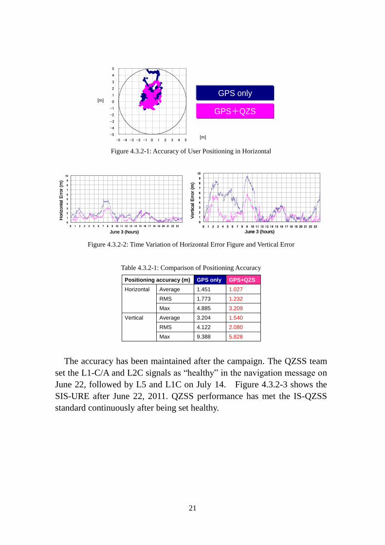
(X-Y plot) is shown in Figure 4.3.2-1, and the time variation of horizontal
and vertical errors are shown in Figure 4.3.2-2 respectively, comparing
between GPS-only-positioning and GPS + QZSS positioning. The
summary of the user positioning error is shown in Table 4.3.2-1.
From Figure 4.3.2-1, 4.3.2-2 and Table 4.3.2-1, the user positioning
accuracy improves greatly by adding QZSS, due to DOP (Dilution of
Precision) and ionospheric correction improvement. These results prove
the high interoperability between GPS and QZSS from the view of users.
-4.0
-3.0
-2.0
-1.0
0.0
1.0
2.0
3.0
4.0
2011/6/3 2011/6/5 2011/6/7 2011/6/9 2011/6/11 2011/6/13 2011/6/15
SIS-URE[m
]
SIS-URE[m]
仕様値spec
21
Figure 4.3.2-1: Accuracy of User Positioning in Horizontal
Figure 4.3.2-2: Time Variation of Horizontal Error Figure and Vertical Error
Table 4.3.2-1: Comparison of Positioning Accuracy
The accuracy has been maintained after the campaign. The QZSS team
set the L1-C/A and L2C signals as “healthy” in the navigation message on
June 22, followed by L5 and L1C on July 14. Figure 4.3.2-3 shows the
SIS-URE after June 22, 2011. QZSS performance has met the IS-QZSS
standard continuously after being set healthy.
-5
-4
-3
-2
-1
0
1
2
3
4
5
-5 -4 -3 -2 -1 0 1 2 3 4 5
GPS only
GPS+QZS
-5
-4
-3
-2
-1
0
1
2
3
4
5
-5 -4 -3 -2 -1 0 1 2 3 4 5
GPS only
GPS+QZS
0
1
2
3
4
5
6
7
8
9
10
0 1 2 3 4 5 6 7 8 9 10 11 12 13 14 15 16 17 18 19 20 21 22 23
June 3 (hours)
Horizo
nta
l E
rror
(m)
0
1
2
3
4
5
6
7
8
9
10
0 1 2 3 4 5 6 7 8 9 10 11 12 13 14 15 16 17 18 19 20 21 22 23
June 3 (hours)
Horizo
nta
l E
rror
(m)
0
1
2
3
4
5
6
7
8
9
10
0 1 2 3 4 5 6 7 8 9 10 11 12 13 14 15 16 17 18 19 20 21 22 23
June 3 (hours)
Ve
rtic
al E
rro
r (m
)
0
1
2
3
4
5
6
7
8
9
10
0 1 2 3 4 5 6 7 8 9 10 11 12 13 14 15 16 17 18 19 20 21 22 23
June 3 (hours)
Ve
rtic
al E
rro
r (m
)
Positioning accuracy (m) GPS only GPS+QZS
Horizontal Average 1.451 1.027
RMS 1.773 1.232
Max 4.885 3.209
Vertical Average 3.204 1.540
RMS 4.122 2.080
Max 9.388 5.828
Positioning accuracy (m) GPS only GPS+QZS
Horizontal Average 1.451 1.027
RMS 1.773 1.232
Max 4.885 3.209
Vertical Average 3.204 1.540
RMS 4.122 2.080
Max 9.388 5.828
[m]
[m]

22
Figure 4.3.2-3: QZS-1 SIS-URE after June 22, 2011
Full interoperability between GPS and QZSS provides the people in the
East Asia and Pacific region both the higher availability improvement and
user positioning accuracy improvement. QZSS would like to maintain and
pursue the high interoperability with GPS from now and in the future.
4.4. Confirmation of Compatibility between GPS and QZSS
After the launch of Michibiki, the transmission of the navigation signal
started when it was confirmed that harmful interference was not observed.
There have been no harmful effects on GPS signal reception since
Michibiki started signal transmission.
5. Conclusion
This report reviewed and summarized all activities implemented by the
GPS-QZSS Technical Working Group (TWG) and its sub-working group,
EWG since 2002. The technical discussions through TWG/EWG
contributed to realization of compatibility and interoperability between
GPS and QZSS.
Japan has decided to accelerate the deployment of the operational QZSS
as expeditiously as possible. More specifically, a four satellite
constellation shall be established by the late 2010s. In the future, a seven
satellite constellation shall be completed to enable sustainable positioning.
The QZSS and the results of the TWG are expected to take a more
important role in maximizing GNSS user benefits in the Asia Oceania
region as a result of this decision.

23
Appendix Acronyms
epfd equivalent power flux density
EWG Expert Working Group
GQTO GPS / QZSS Time Offset
GPS Global Positioning System (U.S.)
QZS Quasi-Zenith Satellite
QZSS Quasi-Zenith Satellite System
NICE New and Improved Clock and Ephemeris
NICT National Institute of Information and Communications
Technology
ICD Interface Control Document
ITU International Telecommunications Union
JAXA Japan Aerospace Exploration Agency
KPGO Kokee Park Geophysical Observatory
SBAS Satellite Based Augmentation Service
SAIF Sub-meter class Augmentation with Integrity Function
PRN Pseudo Random Noise
QPSK Quadrature Phase Shift Keying
TWG Technical Working Group (in the context of U.S./Japan
GPS/QZSS cooperation)
TWSTFT Two-Way Satellite Time and Frequency Transfer
U.S. United States of America
USNO U.S. Naval Observatory
UTC Universal Time Coordinated
VLBI Very Long Baseline Interferometry
- End of Document -