Embed Size (px)
Citation preview

U. S. Department of Agriculture S o i l Cons ervat ion Service Engineering Division
Technical Release No. 54 Design Unit October, 1974
STFWCTITRCIl; DESIGN OF SAF STILLING BASINS


PREFACE
This t echn ica l r e lease continues t h e e f f o r t t o produce design a i d s which can serve t o improve t h e e f f i c iency and q u a l i t y of design work. The t echn ica l r e l e a s e deals with t h e s t r u c t u r a l design of SAF s t i l l i n g bas ins . TR-50 deals with t h e s t r u c t u r a l design of rec tangular channels. Taken t o - gether, these two techn ica l r e leases provide a means of obta in ing s t r u c - tural designs f o r e s s e n t i a l l y all sect ions of ordinary, s t r a i g h t i n l e t , chute spil lways on e a r t h foundations. This mate r i a l should be useful t o both planning and design engineers s ince e i t h e r prel iminary o r d e t a i l de- s igns may be obtained.
A d r a f t of t h e subject t echn ica l r e l e a s e dated July, 1974, was sen t t o 9 t h e Ehgineering and Watershed Planning Unit Design Engineers f o r t h e i r
review and comment.
5 This t echn ica l r e l e a s e w a s prepared by M r . Edwin S. U l i n g , Head, Design Unit, Design Branch a t Hyat tsvi l le , Maryland. He a l s o wrote t h e computer program.


TECHNICAL R-SE m E R 54
STRUCTUR.CIL DESIGN O F SAF STILLING BASINS
Contents
Introduction
Types of SAF S t i l l i n g Basins Type (A) Type ( B ) Type ( c ) Wingwalls
Loading Conditions Surcharge Load Condition No. 1 Load Condition No. 2 F lo ta t ion Requirements Sl id ing Requirements
Sl id ing forces Momentum considerat ions Possible modification of load condition No. 2
Design Parameters Primary Parameters Secondary Parameters
Design C r i t e r i a
Preliminary Des igns l'Y-pe (A)
Sidewall geometry and load m i a b l e s Sidewall bending F lo ta t ion Bearing pressures Floor s l a b shear Floor s l a b bending Sl id ing Momentum changes at break-in-grade
Type (B) Sidewall bending F lo ta t ion Bearing pressures Floor s l a b shear and bending S l id ing
Type (c) Pavement s l a b design
F lo ta t ion Bearing pressures Sl id ing Long it ud inal shear and bend ing

Retaining w a l l port ions Bearing pressures Base s lab shear and bending
Wingwalls Loading condit ions Wingwall bending Overturning Sl id ing Wingwall-to -bas i n t i e
Deta i l Designs Sidewall s t e e l Floor s lab s t e e l Base s lab s t e e l Pavement s lab s t e e 1 Wingwall s t e e l
Concrete Volumes Basin Volumes Wingwall Volumes
Sidewall s tub adjustment Toewall s tub adjustment Basin foot ing adjustment
Computer Designs Input Output
Messages Preliminary designs Deta i l designs
Type ( A ) m e ( B ) Type ((9 Wingwall s
Appendix
Toewall thickness and s t e e l f o r SAF s t i l l i n g basins

Figures
Figure 1 Figure 2 Figure 3 Figure 4 Figure 5 Figure 6 Figure 7 Figure 8
Figure 9 Figure 10
Figure 11 Figure 12 Figure 13 Figure 1 4 Figure 15 Figure 16 Figure 17 Figure 18 Figure 1 9
Figure 20
Figure 21 Figure 22 Figure 23 Figure 24 Figure 25 Figure 26 Figure 27 Figure 28 Figure 29
Figure 30
Figure 31
Figure 32 Figure 33 Figure 34 Figure 35 Figure 36 Figure 37 Figure 38 Figure 39 Figure 40
Figure 41 Figure 42 Figure 43 Figure 44
Type (A) SAF s t i l l i n g basin Type (B) SAF s t i l l i n g basin Type (c) SAF s t i l l i n g basin Wingwall layout Variation i n e a r t h f i l l surface Load condition No. 1 Load condition No. 2 Horizontal components of hydrostat ic forces, load condition No. 1 Sl iding forces, load condition No. 2 Momentum re la t ions i n bas i n
Sidewall dimensions and thicknesses Section and e a r t h f i l l heights Tailwater depths f o r load condition No. 2 Considerations f o r sidewall bending, type ( A ) basin Thickness at bottom of section, when HBW > HWW Determination of control l ing thickness Components of sidewall and s lab volumes Components of volume of water i n basin Footing pressures and load components f o r LC #1 o r LC #2 Components of up l i f t f o r LC #1 or LC #2
Determination of bearing pressures f o r LC #2 Loads f o r f loor s lab shear and bending Considerations f o r sidewall bending, type ( B ) bas i n Some type (B) components Dis t r ibut ion of bearing pressures, type ( B ) Equivalent beam and loading Division of horizontal force, LC #2 Pavement s lab components Determination of pavement s lab bearing pressures,
#I Shear and moment i n pavement slab, LC #2
Determination of re ta ining wal l port ion bearing pressures Retaining w a l l port ion l a t e r a l force moments, LC #2 Loadings fo r base s lab shear and moment Wingwall design sect ion Wingwall e a r t h f i l l surfaces and slopes Load conditions f o r wingwall design Determination of wingwall thickness Wingwall footing projections Wingwall overturning and bearing Longitudinal s l i d ing of wingwall
Wingwall-to-basin t i e s t e e l a rea Sidewall s t e e l layout and point locat ions Sidewall s t e e l determination Floor s lab s t e e l layout and point locations

Figure 45 Figure 46 Figure 47 Figure 48 Figure 49 Figure 50
Figure 51 Figure 52 Figure 53 Figure 54 Figure 55 Figure 56 Figure 57
Base s l a b s t e e l layout and point loca t ions Pavement s l a b s t e e l layout and point loca t ions Wingwall s t e e l point l o c a t ions Wingwall sec t ion s t e e l layout Determination of force system at a point i n wingwall Determination of force system i n wingwall foot ing
Wingwall volume without adjustments Corner d e t a i l , wingwall-s idewall Possible bas in foot ing adjustment volumes Computer output, prel iminary designs Computer output, type ( A ) d e t a i l design Computer output, type ( B ) d e t a i l design Computer output, type ( c ) d e t a i l design
Tables
Table 1 Table 2
Secondary parameters and de fau l t values Input values per design run

Not a l l nomenclature is l i s t e d . Hopefully t h e meaning of any un l i s t ed nomenclature may be ascer ta ined from t h a t shown. T r a i l i n g l e t t e r s U o r D a r e used wi th some va r i ab les . This s i g n i f i e s va r i ab les associa ted wi th t h e upstream o r downstream por t ion o f type ( B ) s t i l l i n g bas ins .
A A 1 A2 A, ARM
A T E BACK
BASEL BAT BDN BUP
b CB CC
CF CFSC D
D l D2 DS DW DWD
DZ E F 1 FBOT l?Hl FI-I2 mwD
- required re insorc ing s t e e l a rea = a r e a of r i g h t sec t ion a t one end of prismatoid = a r e a of r i g h t sec t ion a t opposi te end of prismatoid = a r e a of mid-section of prismatoid E dis tance from B-line t o underside of upstream sect ion;
moment arm of wingwall-to -bas i n t i e f required s t e e l a r e a of wingwall-to-basin t i e G dis tance used t o define t h e wingwall foo t ing extension back
t o t h e s idewal l = hor izon ta l l eng th of bas in projec ted bearing a r e a - r a t e of b a t t e r of ins ide su r face o f lower p a r t of s idewal l z foo t ing p ro jec t ion a t downstream end of wingwall =- foo t ing projec t ion a t upstream end of wingwall-section a t
a r t i c u l a t i o n j o i n t
= width of re inforced concrete member r d i r e c t compressive fo rce i n t h e f l o o r s l a b between s idewal ls = const ruct ion condit ion, a loading condit ion inves t iga ted in
wingwall des ign = d i r e c t compressive fo rce i n t h e foo t ing p ro jec t ion - c o e f f i c i e n t of f r i c t i o n , s o i l t o concrete = e f f e c t i v e depth of concrete sec t ion; diameter of r e in fo rc ing
ba r E entrance depth of water t o SAP s t i l l i n g bas in r t h e sequent depth t o depth D l = a sequent depth z depth of water i n bas in; t a i l w a t e r depth i n wingwall design = DW - ~ 1 1 2 - depth of water i n bas in above s e c t i o n under cons idera t ion E e c c e n t r i c i t y of VNET - Froude's number = V12/g~1 = uniform t a n g e n t i a l loading on bottom of pavement s l a b = hor izon ta l component of hydros ta t ic fo rce due t o HUP1 = hor izon ta l component of hydros ta t i c fo rce due t o HUP2 = t h e p a r t of l?H2 x W c a r r i e d by downstream por t ion of type ( B )
bas i n FLOATR - s a f e t y f a c t o r aga ins t f l o t a t i o n FM = fo rce due t o hor izon ta l change i n momentum FKL = momentum fo rce a t sec t ion of depth D l
lM2 = momentum fo rce a t sec t ion of depth HTW2 -
FS2 = m + m FSLIDE = r e s u l t a n t of t h e hor izon ta l d r iv ing forces tending t o cause
s l i d i n g of t h e bas in FT1 = hor izon ta l component of hydros ta t i c fo rce due t o HTW1

v i
FTG FTOP Fx 1 Fx2 f c fs
GB GM GS g HB
HBD HBn HBW HBZ HDIFF
HN HNm
HS HSHV HSn HSW Hnnn m HTw1
HlTP
rnl
Humn HUW HV
HVZ Hw
HWm m HWW Hwz
HX
h ILC J KO L;B
z foot ing pro,: &ion = uniform t a n g e n t i a l loading on top of pavement s l a b 5 hydros ta t ic force due t o depth D l = hydros ta t ic fo rce due t o depth HTW2 r compressive s t r e s s i n concrete = s t r e s s i n re inforc ing s t e e l
= GS - 62.4 z moist un i t weight of e a r t h f i l l r sa tu ra ted un i t weight of e a r t h f i l l = 32.2 f t per sec2 - e a r t h f i l l height above top of f l o o r of bas in at downstream end
of bas in = HBW - ~ / 1 2 z e a r t h f i l l height at sec t ion n = working value of height of e a r t h f i l l E height of e a r t h f i l l above sec t ion under considerat ion = (KEN - HWW) o r (KBw - HUW)
r v e r t i c a l component of d i s t ance N = ne t hor izonta l fo rce per un i t length a c t i n g on wingwall design
s e c t ion r v e r t i c a l r o j e c t i o n of inc l ined f l o o r s l a b = (I~SW - HVP o r (J - W) r height of sec t ion n = working value of height of sec t ion = t a i l w a t e r depth at sec t ion n f o r load condition m = depth of toewall below top of f l o o r of bas in 5 t a i l w a t e r depth above top of f l o o r of bas in f o r load condit ion
No. 1 u p l i f t head above top of f l o o r of bas in f o r load condition under cons ide ra t ion
u p l i f t head above top of f l o o r of bas in f o r load condit ion No. 1
5 u p l i f t head at sec t ion n f o r load condit ion m = working value of u p l i f t head a t sec t ion under considerat ion = t h e d is tance over which t h e ins ide surface of t h e sidewall
is v e r t i c a l 5 ba t t e red height of s idewall above sec t ion under considerat ion
u p l i f t head above top of wingwall foo t ing a t t h e a r t i c u l a t i o n j o i n t f o r load condit ion under inves t igat ion shear a t bottom of s idewal l at sec t ion under inves t igat ion
= HWW - ~112 = working value of water head on outs ide of s idewall - height of water head above sec t ion under considerat ion
r depth of water over top of pavement s l a b at XDN from down- stream end
= perpendicular d is tance between r i g h t end sect ions intermediate load condit ion used i n wingwall design
= height of s idewall above top of f l o o r of bas in = l a t e r a l e a r t h pressure r a t i o 5 l eng th of SAF stilling basin
LBOT = l eng th of bottom of type (A) basin

v i i
L C # ~ load condit ion No. 1 LFVEL 2 dis tance used t o l oca t e t h e wingwall a r t i c u l a t i o n jo in t with
respect t o the corner of t h e sidewall LN = hor izonta l component of d is tance N
LS = hor izonta l project ion of incl ined f l o o r s l ab LTOP length of top of sidewall of type (A) , bas in LTOT Z overa l l length of type ( B ) and ( c ) basins M bending moment; moment of forces about some moment center MA = moment of forces about t he A-line of type (c ) basins MAXFI'G = maximum acceptable sidewall foot ing project ion MB 5 moment of forces about t he B-line of type ( c ) basins MC = bending moment at t h e center of t h e f l o o r s l ab MDN r e su l t an t moment of t h e forces on t h e downstream por t ion about
t he hinge MP = bending moment i n pavement s l a b
% equivalent moment, moment about ax i s a t t he tens ion s t e e l J!E2IE 2 bending moment used t o obta in ATlE at wingwall-to-basin t i e MUP z r e su l t an t moment o f t h e forces on t h e upstream por t ion about
t he hinge MZ 5 bending moment a t sect ion under considerat ion N = height of sidewalls at upstream end section; d i r e c t compressive
fo rce i n sidewall N U T = bearing force between pavement s l ab and re ta in ing w a l l por t ion NWALZ; 2 d i r e c t fo rce of wingwall NZ - d i r e c t compressive force a t sec t ion under considerat ion PALLOW mubum allowable bearing (con tac t ) pressure PARM dis tance between PWALL and v e r t i c a l face of sidewall
PAVER PB PBG PBH PBT PDH PDN PDT PDW PF
PFn PLXlNG m FTS PUH PUP PUT PUW PWAm PX
= average bearing pressure r bearing pressure a t sect ion under invest igat ion = bearing pressure a t break-in-grade = bearing pressure at heel of r e t a i n ing w a l l port ion = bearing pressure a t t oe of re ta in ing w a l l port ion = bearing pressure at heel of downstream end sect ion = bearing pressure a t downstream end sect ion = bearing pressure a t t o e of downstream end sect ion = water pressure in bas in - pressure on foot ing project ion
= pressure on foot ing project ion at sec t ion n - ne t longi tudinal shearing forces assumed ca r r i ed by sidewalls = ne t uniform loading between sidewalls = dead weight of f loor s l ab = bearing pressure at heel of upstream end sect ion
bearing pressure a t upstream end sec t ion bearing pressure at t o e of upstream end sec t ion u p l i f t pressure on underside of s l ab - d i r e c t fo rce of sidewall bearing pressure on pavement s l ab at XDN from downstream end
pcf - pounds per cubic foo t psf - pounds per square foo t

v i i i
P t = temperature and shrinkage s t e e l r a t i o Q E SAJ? s t i l l i n g basin discharge Q U m r quantity, volume of s t i l l i n g basin o r associated wingwalls q - uni t discharge S r maximum allowable spacing of re inforcing s t e e l SDOm 5 sum of a l l downward forces ac t ing on a basin o r port ion SLIDER safe ty f ac to r against s l i d ing SUP
sz
T T ' T" TABn TADD TB TBB TBV TM
TPBG TPDN T W P TS TSB
TSBG TSDN TSR TSUP TSV
a TTW TV TVn
TW
TWF TWT TWW TX ULONG
UX U
v
V1 V2 m G
= sum of a l l u p l i f t forces ac t ing on a basin o r port ion
5 maximum allowable spacing of re inforcing s t e e l a t sect ion under consideration
= required thickness - required thickness at bottom of sect ion due t o T = HSHV x BClT r required thickness at bottom of sec t ion n 5 thickness t o be added f o r cover
thickness a t bottom of sidewall 5 thickness a t bottom of sidewall due t o b a t t e r of ins ide face = thickness a t bottom of sidewall exclusive of TBB = required thickness due t o bending moment
thickness of pavement s l ab a t break-in-grade 5 thickness of pavement s lab a t downstream end sect ion z thickness of pavement s lab at upstream end sect ion r thickness of slab; thickness required f o r shear - thickness required a t bottom of sidewall due t o required TV
at HV - s lab thickness at break-in-grade = s lab thickness a t downstream end sect ion r required s lab thickness r s lab thickness a t upstream end sect ion - thickness required a t bottom of sidewall if HSW > HV
= thickness at top of widewall 5 thickness of toewall
thickness of sidewall at HV from top of sidewall = required thickness of sidewall at HV from top of s i d e w d l at
sect ion n 2 working thickness of inclined f l oo r s lab at XBG from break-in-
grade = thickness of wingwall foot ing
thickness of wingwall toewall z thickness of wingwall = thickness of pavement s lab a t XDN from downstream end - net longi tudinal shearing forces assumed carr ied by f loor o r
base s lab
= u p l i f t head on pavement s l ab at XDN from downstream end = f l exu ra l bond s t r e s s i n concrete - concrete volume; shearing force at sect ion under considera-
t ion - entrance veloci ty of water t o SAF s t i l l i n g basin = V l x ~1/El?W2 r basin footing adjustment volume
WETI = SDOWN - SUP

VRUP
WOAD VZ v W WDES
WOB
ZH ZNS m ZPS ZS Y
- shear i n pavement s l ab = resu l tan t of t h e v e r t i c a l forces ac t ing on t h e downstream por-
t i o n of type (B) basin - resu l tan t of t h e v e r t i c a l forces ac t ing on t h e upstream portion of type (B) bas in
= toewall stub adjustment volume = sid-11 stub adjustment volume = volume of wingwalls exclusive of VETG; r e su l t an t v e r t i c a l force
on wingwall = wingwall volume without adjustments r shear at sec t ion under consideration
shewing s t r e s s i n concrete r width of SP s t i l l i n g basin = perpendicular d is tance from sidewall t o t h e point where t he out-
s i de edge of t h e wingwall footing i n t e r s ec t s t he p l m e of t h e downstream end sect ion
r perpendicular distance from sidewall t o t h e point on t h e out- s i de edge of t h e wingwall footing t h a t is i n t h e plane of t he a r t i cu l a t i on jo in t
= overa l l width of s t i l l i n g basin
overa l l width of re ta in ing w a l l base; overa l l width of w i n g w a l l base
=- w i n g w a l l projection, t h e perpendicular distance from the s ide- wall t o t h e f a r t h e s t point on t he outs ide edge of t he wingwall foot ing
r perpendicular d is tance from t h e sidewall t o t h e point of i n t e r - sect ion of w i n g w a l l toewall and plane of downstream end sect ion
r perpendicular d is tance from t h e plane of t h e downstream end sec- t i o n t o t h e point where t h e wingwall foot ing extended backward would i n t e r s ec t t h e outer edge of t he sidewall
= t oe length of re ta in ing w a l l base; distance from a r t i cu l a t i on jo int t o any v e r t i c a l sect ion of t he wingwall
= dis tance from break-in-grade t o any v e r t i c a l sect ion of t he in- cl ined f l oo r s l ab
= dis tance from downstream end t o any v e r t i c a l sect ion of t h e pavement s l ab o r re ta in ing w a l l port ion - width of pavement s lab
r e a r t h f i l l height above top of w i n g w a l l footing a t dis tance X from a r t i cu l a t i on jo int
= height of water on back face of t he wingwall at dis tance X from a r t i cu l a t i on jo in t
r dis tance from moment center t o VNFT; distance from top of s ide- w a l l t o sect ion under consideration; d is tance from outer edge of wingwall footing t o sect ion under consideration
r slope hypotenuse parameter r slope parameter used t o define an e a r t h f i l l slope - a slope parameter used t o define an e a r t h f i l l slope = a slope parameter used t o define an e a r t h f i l l s lope r slope parameter f o r inclined port ion of s t i l l i n g basin = 62.4 pcf


TECHNICAI; RELEASE NUMBER 54
STRUCTURAL DESIGN OF SAF STILLJT?G BASINS
Introduction
This t echn ica l r e lease i s concerned with t h e s t r u c t u r a l design of SAF s s t i l l i n g basins. The hydraulic c r i t e r i a f o r t h e dimensions of SAF out-
l e t s were developed by Fred W. Bla isdel l , Hydraulic Engineer, ARS, St . Anthony F a l l s Hydraulic Laboratory. These c r i t e r i a a r e presented i n National Engineering Handbook, Section 14, "Chute Spillways, " wri t t en by Paul D. Doubt, formerly Head, Design Unit, SCS, Hyat tsvi l le , Maryland,
The mater ia l presented here in t r e a t s t h e s t r u c t u r a l design of rectangular s t i l l i n g basins having t h e general layout indicated on Ehgineering Stand- a rd Drawing ES-86, sheet 1, contained i n NEX-14. This mater ia l does not include hydraulic design which must preceed s t r u c t u r a l design. It i s assumed these s t r u c t u r a l designs w i l l be obtained from computers although t h e bas ic approach i s independent of computer usage. Technical Release No. 50, %sign of Rectangular S t ruc tu ra l Channels, " can be used t o ob- t a i n preliminary and d e t a i l s t r u c t u r a l designs of chute spillway sect ions upstream of t h e s t i l l i n g basin.
A computer program w a s wr i t t en i n FORTRAN f o r IBM 360 equipment t o per- form these SAF s t i l l i n g basin designs. The program operates i n two modes. It w i l l execute preliminary designs t o a i d t h e designer i n s e l e c t i n g t h e type of basin he d e s i r e s t o use i n f i n a l design. The program w i l l a l s o execute t h e d e t a i l design of specj f ied basins. Concrete thicknesses and dis tances a r e determined and s t e e l requirements, i n terms of required a r e a and maximum spacing, a r e evaluated a t various loca t ions . Actual s t e e l s i z e s and layouts a r e not se lec ted , these a r e t h e prerogative of t h e des igner . This t echn ica l r e lease documents t h e c r i t e r i a and procedures used i n t h e computer program, explains t h e input d a t a required t o obta in a design, and i l l u s t r a t e s computer output f o r preliminary and d e t a i l designs. At t h e present time designs may be obtained by requests t o t h e
Head, Design Unit Ehgineering Division S o i l Conservation Service Federal Center Building Hyat tsvi l le , ~ a r y h n d 20782.
Input information which must be provided f o r each design run, is d i s - cussed under t h e sec t ion, "Computer Designs, Input."

Types of SAF S t i l l i n g Basins
Three types of SAF s t i l l i n g basins a r e t r ea t ed herein. Each type may be thought of a s a s t r uc tu r a l va r ia t ion of t h e SAF o u t l e t shown on ES-86, sheet 1, and each uses t he a l t e rna t e jo int d e t a i l given i n t h a t drawing. A l l types a r e assumed symmetrical i n both construction and loading about the longi tudinal cen te r l ine of t he basin a s wel l a s about t h e v e r t i c a l cen te r l ine of any transverse cross section. Each basin i s designed f o r t he two loading conditions described i n t h e next section, and each must s a t i s f y both f l o t a t i o n ( u p l i f t ) requirements and s l i d ing requirements . See Figures 1-3 f o r def in i t ion sketches of t h e th ree types of basins. These sketches present idealized s t i l l i n g basins and do not show chute blocks, f l o o r blocks, end sills, f i l l e t s on toewalls, upstream f loo r jo int steps, o r w i n g w d s . The wingwdls a r e omitted from these sketches f o r c l a r i t y and because t h e wingwall and basin proper a r e designed t o a c t e s sen t i a l l y independently of each other.
Any one of t h e th ree types of SAP s t i l l i n g basin may be most advantageous fo r a particular s e t of design conditions. Because of t h e l a rge number of parameters involved, it i s of ten not read i ly apparent which type w i l l be bes t i n a given s i tua t ion .

Type (A) This type, s e e F igure 1, most c l o s e l y approximates t h e SAF o u t l e t o f ES-86. S t r u c t u r a l l y , t h e bas in i s a monoli thic u n i t . The f l o o r s l a b th i cknesses vary uniformly from t h e downstream end o f t h e bas in t o t h e break-in-grade, and from the break-in-grade t o t h e upstream end.
W - 7 -
TRANSVERSE SECTION THRU FLOOR OF BASIN
L TOP
HN SIDEWALL
HS
C7
TOEWALL
Figure 1. Type ( A ) SM s t i l l i n g b a s i n
L S \ r
i LBOT m-
LONGITUDINAL SECTION
+ L B
A * - +-TTW

Type (B) This type, see Figure 2, has a t ransverse a r t i cu l a t ed jo in t a t t h e break- in-grade. Some form of f l oo r jo in t s t ep i s normally used a t t h i s jo int . The upstream end sect ion is ve r t i c a l , r a the r than normal t o t h e plane of t h e inclined f loor s lab. The doweled, transverse a r t i cu l a t i on jo int makes t he s t r u c t u r a l behavior of t h i s type of SA.F d i f f e r from t h a t of type ( A ) .
(FOOTING PROJECTION IS FTGU UPSTREAM OF BREAK-IN-GRADE1
TRANSVERSE SECTION THRU FLOOR OF BASIN
DOWELED A R TICUL A TION
N JOINT *
L TOT +
LONGITUDINAL SECTION
0 HTW
Figure 2. Type (B) SAF s t i l l i n g basin

T m e (c ) This type, see Figure 3, has independent r e t a i n i n g w a l l por t ions and pavement s l ab . The pavement s l a b r e s i s t s any t h r u s t imposed on it by t h e r e t a i n i n g wall port ions. The most advantageous t o e length, X, is determined i n t h e design.
TRANSVERSE SECTION THRU FLOOR OF BASIN
L TOT
I- - I LONGITUDINAL SECTION
THRU RETAINING WALL PORTION
Figure 3. Type (c) SAT s t i l l i n g b a s i n
Wingwalls
The wingwall i s ar t iculated from the basin sidewall. Hence each w a l l ac t s as a simple cantilever. The wingwalls with t h e i r footings are not included i n the s t a b i l i t y analyses of the basin proper. Figure 4 gives the wingwall
Figure 4. Wingwall layout

layout. The l e v e l distance locat ing t h e m t i c u l a t i o n jo int va r ies de- pending on r e l a t i v e values of wingwall and sidewall thicknesses. This distance i s discussed subsequently.
Loading Conditions
Two loading conditions a r e considered i n t he design of SAF s t i l l i n g basins. Parameter values should be selected so t h a t these loading condi- t ions r e f l e c t extremes of probable conditions. The surface of t h e earth- f i l l against t h e sidewall va r ies l i n e a r l y from t h e top of t h e w a l l a t t he
Figure 5. Variation of e a r t h f i l l surface
upstream end t o a height, HB, at the downstream end, see Figure 5 .
Surcharge
Surcharge i s not included herein as a spec i f ic loading. The e f f ec t s of surcharge can be duplicated t o some extent by a r b i t r a r i l y increasing l a t e r a l pressure r a t i o s , uni t s o i l weights, o r e a r t h f i l l heights. In- creasing t h e l a t e r a l pressure r a t i o , KO, is t he preferred approach un- l e s s t he surcharge i s applied constantly.

Load Condition No. 1
This i s t h e no flow loading, see Figure 6. It i s meant t o represent conditions following a rapid lowering of t h e water surface i n t h e bas in before t h e water t a b l e i n t h e e a r t h f i l l , and associated uplift, have lowered s ign i f i can t ly from some higher l e v e l . The t a i l w a t e r depth i n t h e bas in is IflW1. The u p l i f t head above t h e top of t h e l e v e l f l o o r s l a b and foot ings i s HUP1. This loading should maximize t h e d i f ference be- tween HlTPl and HTW1.
Figme 6 . Load condit ion No. 1

Load Condition No. 2
This i s t h e full flow loading, see Figure 7. Flow en te r s t h e s t i l l i n g bas in at a depth, D l , and veloci ty , V1. These a r e t h e hydraulic para- meters discussed i n NEH-14 on pages 2.193 and following. Although it i s admittedly a rough approximation, t h e water surface i n t h e basin is a s s h e d t o vary l i n e a r l y from t h e depth, D l , at t h e break-in-grade t o ...~.. >
' t he t a i l w a t e r depth, W 2 , a t t h e downstream end. The u p l i f t head above t h e t o p of t h e l e v e l f l o o r s l ab and footings is HUP2. Load condit ion No. 2 is meant t o represent governing condit ions when t h e bas in i s oper- a t i n g at f u l l flow. Thus t h i s loading should maximize both HTW2 and H U E . The water surface on t h e outs ide of t h e bas in w a l l s i s taken as HUE f o r a l l analyses except s idewall bending. Observe t h a t t h e follow- ing r e l a t i o n s must e x i s t between t h e various water height parameters:
SECTION AA
Figure 7. Load condit ion No. 2

Flo ta t ion Requirements
The t o t a l weight of t h e SAF s t i l l i n g basin plus a l l downward forces a c t - ing on it must exceed t h e u p l i f t fo rces by a s u i t a b l e s a f e t y f a c t o r under a l l conditions of loading. Often t h e most c r i t i c a l case is load condition No. 2. However, with a s u f f i c i e n t l y l a r g e d i f ference between H U P l and FIW1, load condition No. 1 w i l l cont rol . Hence both load conditions a r e inves t igated . The f l o t a t i o n s a f e t y fac to r , FLOATR, i s se lec ted by t h e user. Footing projec t ions a r e provided, when required, t o develop neces- sa ry add i t iona l downward forces .
S l id ing Requirements
The hor izonta l r e s i s t i n g fo rces t h a t can be mobilized must exceed t h e hor izonta l dr iv ing forces ac t ing on t h e basin i n a downstream d i r e c t i o n by a s u i t a b l e s a f e t y f a c t o r under a l l condit ions of loading. E i the r load condition can control , hence both a r e inves t igated . The s l i d i n g sa fe ty fac to r , SLIDER, is se lec ted by t h e user .
The fo rces r e s i s t i n g s l i d i n g a r e t h e f r i c t i o n a l r e s i s t ance between t h e basin and t h e foundation, t h e f r i c t i o n a l r e s i s t ance between t h e sidewalls and t h e e a r t h f i l l , t h e passive res i s t ance of t h e channel mater ia l down- stream of t h e toewall, and c e r t a i n hydros ta t ic pressures discussed below. The f r i c t i o n a l fo rce between basin and foundation i s assumed t o a c t along t h e bottom of t h e l e v e l f l o o r s l ab . The f r i c t i o n a l fo rce between t h e s ide- w a l l s and e a r t h f i l l i s neglected a s being extremely unre l iable . The pas- s i v e r e s i s t a n c e of t h e channel mate r i a l downstream of t h e toewall i s neg- l ec ted s ince it may be scoured away.
Sl id ing forces. The hor izonta l components of hydros ta t ic forces of con- cern i n load condit ion No. 1 a r e shown i n Figure 8. Both d r iv ing and r e s i s t i n g hydros ta t ic d i s t r i b u t i o n s a r e shown t o cease at t h e e levat ion of t h e top of t h e f l o o r of t h e basin. While t h i s i s of course untrue, these pressures must reach equil ibrium through dra ins o r o ther seepage,
Figure 8. Horizontal components of hydros ta t ic forces, load condit ion No. 1
and w i l l e s s e n t i a l l y cancel each other below t h a t elevation.
h load condit ion No. 2, t h e hor izonta l fo rce a c t i n g on t h e basin, due t o t h e water in t h e basin, is shown i n Figure 9 as FM. The force, FM, i s due t o t h e change in momentum, i n a hor izonta l d i rec t ion , of t h e water on t h e l e v e l f l o o r slab of t h e basin.

Figure 9. Sl id ing forces, load condition No. 2
Momentum considerations. Figure 10 shows two ta i lwate r conditions with t h e force FM shown as t h e hor izontal force act ing on t he water due t o
F x 2
Figure 10. Momentum re la t ions i n basin
t h e basin. In sketch ( A ) the t a i lwate r i s D2, t h e sequent depth t o depth, D l . In sketch ( B ) t he t a i lwate r i s IfIIW2 which i s shown as l e s s than M . From momentum pr inciples , l e t t i n g Vl, D l , and V2, ETW2 be veloci ty and depth of flow at beginning and end sections respectively,
f o r rectangular channels,and in terms of per foot of width

which by s u b s t i t u t i o n can be w r i t t e n
F M = F l M l - F M 2
where, wi th depths i n ft, v e l o c i t i e s i n fps
FM = ne t fo rce due t o hor izonta l change i n momentum, l b s per f t width of channel
~1~ EM1 = momentum force a t sec t ion of depth, D l , = (% + 1 q V l ) ,
g l b s pe r f t width of channel
7 2
FM2 E momentum force at sect ion of depth, W 2 , = (7 2 l b s p e r f t of width of channel
y = 62.4 l b s per cu f t
g = 32.2 f t per sec2
q = discharge, c f s per f t width of channel
v2 =n x DI/m2
Taking FM = 0 def ines t h e case of a hydraulic jump. The beginning and end depths are sequent depths, the end depth is given by
where a = I 2 DL ( ,/8F1+1 -1)
F, = Froude's number = v ~ ~ / ~ D . Z
When t h e t a i l w a t e r is l e s s than D2, a s i n sketch (B) , FM2 i s l e s s than FML, t h a t is , FM > 0. Hence t h e force , FM, a c t i n g on t h e basin tends t o push t h e bas in downstream. The depth, DS, i s t h e sequent depth t o t h e depth, HTW2. The water surface p r o f i l e i s roughly t h a t shown.
When t h e t a i l w a t e r is more than D2, sketch not shown, FIG2 is more than FM1, t h a t i s FBI < 0. Hence t h e force , FM, ac t ing on t h e basin tends t o push t h e bas in upstream. The jump tends t o move upstream s ince somewhere between t h e depth, D l , and t a i l w a t e r depth the re i s a depth, DS, t h a t i s sequent t o Dl.
However, t h e sum of FM and t h e hor izonta l component of t h e hydros ta t ic fo rce due t o HW2, see Figure 9, is of more concern than considerat ion of t h e v a r i a t i o n of FM alone. Let FH2 be t h e hydros ta t ic fo rce and FS2 be t h e sum force, then i n l b s per f t width of channel
FS2 = FH2 + FM.
For purposes of study, t a k e t h e p a r t i c u l a r case of H U E = W 2 , then
d i f f e r e n t i a t i n g wi th respect t o JEW2 t o f ind t h e value of HTW2 making
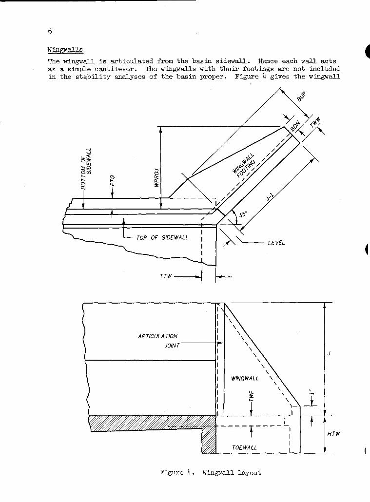
w a l l s , J i s t h e control , so t h a t FS2 maximum would occur when HTW2 = HUE = J.
I n design, t h e condit ion r e s u l t i n g i n t h e minimum a c t u a l f ac to r of s a f e t y agains t s l i d i n g should be checked. This condit ion probably occurs when HTW2 = D2. For higher t a i l w a t e r s than D2, t h e bas in becomes e s s e n t i a l l y fu l l of water so t h a t an increase i n FS2 i s o f f s e t by an increase i n f r i c t i o n a l r e s i s t ance due t o increased water weight. - Possible modification of load condit ion No. 2. As explained i n t h e next sec t ion, HTW2 and HUP2 a r e se lec ted by t h e user . If HUF2 and/or H'TW2
I a r e se lec ted g rea te r than t h e sequent depth, D2, they a r e reduced during - design t o D2. This i s done f o r t h e reasons discussed immediately above, namely, HTW2 = D2 represents a more c r i t i c a l s i t u a t i o n than when H U E and/or HTW2 a r e more than D2.
Design Parameters
There a r e some twenty-two independent parameters involved i n t h e s t ruc - tural design of t h e aforementioned t h r e e types of SAF s t i l l i n g basins. These parameters a r e c l a s s i f i e d as e i t h e r primary parameters o r secondary parameters. Values f o r primary parameters must be supplied by t h e user f o r each design run. Secondary parameters w i l l be assigned de fau l t values i f values a r e not supplied by t h e user . The methods of supplying pasa- meter values a r e discussed under t h e sec t ion, "Computer Designs."
Primary Parameters
W r width of SAF s t i l l i n g basin, i n f t
J height of basin sidewalls , i n f t
LB = l eng th of basin, i n f t
N = height of sidewalls a t upstream end sect ion, i n f t
D l = entrance depth of water t o SAF s t i l l i n g basin, i n f t
V1 = entrance ve loc i ty of water t o SAF s t i l l i n g basin, i n f p s
Secondary Parameters
The secondary parameters and t h e i r defaul t values axe l i s t e d i n Table 1. The user should make an e f fo r t t o evaluate t h e secondary parameter values he wishes t o use. Use of defaul t values may r e s u l t in an overly conserva- t i v e ( o r unconservative) design. Usage of t h e various parameters i s ex- plained where f i r s t encountered. The defaul t value f o r HTW2 is a func- t i o n of D2, t h e sequent depth t o depth D l . The value of Froude's number is computed and it, and D2 a r e output wi th t h e parameter values se lec ted f o r t h e design run.

Table 1. Secondary parameters and defaul t values
Parameter Default Value
m 2 H U E m1 Hun
HB ZS HTW TTW
GM GS KO BAT
M.AxFrG FLOATR SLIDER CFSC
t a i lwa te r depth above top of f l o o r of bas in f o r load condit ion No. 2, i n f t D2 = u p l i f t head above top of f l o o r of basin f o r load condit ion No. 2, i n f t ~1372 r t a i lwa te r depth above top of f l o o r of basin f o r load condition No. 1, i n ft 0 = u p l i f t head above top of f l o o r of bas in f o r load condition No. 1, i n f t 0.5 HUE
= e a s t h f i l l height above t o p of f l o o r of basin a t downstrean end of? basin, i n f t O.5J = slope parameter of incl ined por t ion of s t i l l i n g basin 3 0 = depth of toewall below top of f l o o r of basin, i n ft 4.0 = thickness of toewall, i n inches 10.0
G moist un i t weight of e a r t h f i l l , i n pcf r sa tura ted un i t weight of e a r t h f i l l , i n pcf = l a t e r a l e a r t h pressure r a t i o G ins ide sidewall b a t t e r , i n inches per f t of height
r maximum acceptable footing project ion, i n f t = sa fe ty f a c t o r against f l o t a t i o n 3 safe ty f a c t o r against s l i d i n g = coef f i c ien t of f r i c t i o n , s o i l t o concrete

Design C r i t e r i a
Materials
Class 4000 concrete and intermediate grade s t e e l a r e assumed.
Working Stress Design
Design of sections i s i n accordance with working s t r e s s methods. The allowable s t r e s s e s i n p s i a r e
Ektreme f i b e r s t r e s s i n f lexure f, = 1600
Shear, v / ~ D * v = 70
Flexural Bond tension top bars
o ther tension bars u = 4.8-/~
S t ee l i n tens ion
i n compression, axially loaded
Minimum Slab Thicknesses
Walls Bottom s labs
Temperature and Shrinkage S tee l
The minimum s t e e l r a t i o s a r e f o r unexposed faces
for exposed faces
10 inches 11 inches
Slabs more than 32 inches th ick a r e taken as 32 inches.
Web Reinforcement
The necess i ty of providing some type of s t i r r u p o r t i e i n t h e s lab be- cause of bending ac t ion is avoided by
( 1 ) l imi t ing t h e shear s t r e s s , as a measure of diagonal tension, so t h a t web s t e e l i s not required, and
( 2 ) providing suf f i c ien t e f fec t ive depth of sec t ions so t h a t compression s t e e l i s not required f o r bending.
Cover f o r Reinforcement
S t ee l cover is everywhere 2 inches except f o r outside s t e e l i n bottom s labs where cover i s 3 inches.
*shear sometimes c r i t i c a l at D from face, sometimes at face, see page 17 of TR-42.

S t e e l Required by Combined Bending Moment and Direct Force
Required a r e a determined as explained on pages 31 - 34 of TR-42, "Single Ce l l Rectangular Conduits - C r i t e r i a and Procedures f o r S t r u c t u r a l Design."
Spacing Required by Flexural Bond
Spacing determined as explained on page 47 of TR-42.
Spacing of Reinforcement
The maximum permissible spacing of any reinforcement i s 18 inches.

Prel iminary Designs
T r i a l concre te t h i cknesses a r e determined f o r va r ious c r i t i c a l dimen- s ions , and pre l iminary concre te volumes a r e computed, dur ing t h e pre- l imina ry design phase of t h e s t r u c t u r a l design of SAF s t i l l i n g bas ins . These q u a n t i t i e s may be increased dur ing d e t a i l design i f computations f o r requi red s t e e l a r e a s i n d i c a t e th icknesses a r e inadequate . Assump- t i o n s , c r i t e r i a , and procedures f o r t h e s e v e r a l bas in types a r e d i s - cussed below. Transverse s t r e n g t h of t h e toewa l l is neglec ted through- ou t t h e s e computations. Topics a p p l i c a b l e t o more than one bas in type a r e presented most f u l l y when f i r s t encountered.
Type (A)
Prel iminary design of t ype (A) bas ins proceeds i n an o r d e r l y manner. F i r s t , s i dewa l l geometry, and load va r i ab l e s , a r e e s t a b l i s h e d . Next, r equ i r ed s idewa l l t h i cknesses f o r w a l l bending a r e determined. Next, t h e b a s i n is checked f o r f l o t a t i o n . Footing p ro j ec t ions , FTG, a r e pro- vided i f requi red . Then, bear ing p re s su res a r e checked t o i n s u r e pos i - t i v e p re s su res w i th in al lowable va lues . Then, f l o o r s l a b th i cknesses a r e checked f o r shear and t r a n s v e r s e bending. F ina l ly , t h e bas in i s checked f o r s l i d i n g . A t any s t a g e o f design a f t e r s idewa l l t h i cknesses a r e determined, th icknesses o r f o o t i n g p r o j e c t i o n s a r e incremented i f found inadequate and t h e design is recyc led accordingly.
Sidewall geometry and load v a r i a b l e s . Sidewall dimensions and th i ck - nesses a r e shown i n Figure 11. The i n s i d e f a c e of t h e s idewa l l i s v e r t i c a l from t h e t o p of t h e s idewa l l down a d i s t ance , HV. This d i s - t ance is t h e l a r g e r of 5/2 o r HN. Below t h e d i s t ance , HV, t h e s idewa l l i s b a t t e r e d f o r i c e p r o t e c t i o n a t t h e r a t e of BAT inches pe r f o o t . BAT may be s e t equal t o zero i f des i r ed . The o u t s i d e f ace of t h e s idewa l l i s a p lane su r f ace .
The s lope hypotenuse parameter, ZH, i s
Thus, w i t h a l l d i s t a n c e s i n f e e t
LN = N/ZH
HN = LN x ZS
HS =J-HN
LS = HS x ZS
LBOT = LS + LB
LTOP = LBOT - LN
I f LTOP is l e s s t han LB, t h a t is, N i s t o o b ig , a message i s given and t h e des ign i s canceled.

L TOP >
TOP OF BATTER
L L - 4 (B1 SIDEWALL SECTION
A LS - -
Figure 11. Sidewall dimens ions and thicknesses
A L B - - --
It i s l a t e r shown t h a t sidewall thicknesses may be controlled at any of t he th ree sections shown i n Figure 12. Hence it i s des i rable t o pre- es tab l i sh various section heights, e a r t h f i l l heights, t a i lwa te r depths, and u p l i f t heads .
(A1 SIDEWALL ELEVATION

Section 2 i s midway between sections 1 and 3, hence f o r section heights, i n f e e t
HS1 = N x ZH/ZS
HS3 = J
HS2 = 0 . 5 ( ~ 1 + HS3)
s imilar ly f o r e a r t h f i l l heights, i n f e e t
HB1 = HS1
m 3 = HB + (J - HB) x LB/LTOP
HB2 = 0.5 (m + I E B ~ )
Figure 12. Section and e a r t h f i l l heights
Tailwater depths, i n f ee t , on t h e various sect ions can be obtained from Figure 13 f o r load condition No. 2 a s
~ ~ 2 1 = H S ~ - ( J - m 2 )
i f HT21 < 0 s e t ET21 = 0
i f HT22 < 0 s e t HT22 = 0
Tailwater depths f o r load condition No. 1, HT11, HT13, and HT12 can be determined similarly, l ikewise f o r u p l i f t heads HU21, HU23, HU22, and

Figure 13. Tailwater depths f o r load condit ion No. 2
Sidewall bending. The sidewall i s analyzed a s a s e r i e s of can t i l ever beams of un i t width. The thickness a t t h e top of t h e w a l l , TT, i s s e t at 10 inches. E i the r load condition No. 1 (LC #1) o r load condit ion No. 2 (LC #2) can control w a l l thickness requirements. Because (1) both shear and moment increase exponential ly with depth, and ( 2 ) HI3 may range
Figure 14. Considerations f o r s idewal l bending, type ( A ) basin
from zero up t o J, t h e following is t r u e . The thickness required at t h e bottom of any sec t ion may be governed by t h e thickness required by f l exure a t t h e bottom of t h a t sec t ion o r by t h e thickness required a t t h e bottom of e i t h e r of t h e o the r two sect ions . Therefore t h e f i rs t s t e p i n design- ing t h e sidewall is t o obta in t h e thicknesses required a t t h e bottoms of sec t ions 1, 2, and 3.

The thickness at t h e bottom of t he w a l l at any sec t ion i s se lected as t h e l a rge s t thickness required by: shear f o r LC #1, moment and d i r ec t force f o r LC #1, shear f o r LC #2, o r moment and d i r e c t force f o r LC #2. I l l u s t r a t i v e computations f o r a sect ion of height, HSW, and a poss ible loading case follow. See Figure 15 fo r de f i n i t i on of symbols.
YSW
-
(A) WORKING LOADINGS (B)
Figure 15. Thickness a t bottom of sect ion when HBW > HWW
The working values HSW, W, HWW, and IN a r e obtained from HSn, HBn, HUln o r HT2n, and IITln o r Dl values as appropriate t o t h e sect ion under invest igat ion . Let HDIFF = HEM - HWW For any e f fec t ive depth, D, i n inches
HBD = HBW - ~ / 1 2
HWD = HWW - ~ / 1 2
IlwD = aJ - ~ / 1 2
Then t he shear, i n l b s per f t , at D from the face f o r the case shown i s :
V = 31.2 x (HWD2 - I%$) + KO x GM x HDIFF x (0.5 x HDIFT + HWD)
+ 0.5 x KO x GB x HWD2
where GB = GS - 62.4 is t he buoyant weight of t h e e a r t h f i l l , i n pcf

An i t e r a t i v e process i s required s ince t h e assumed D must agree with t he computed required D. When t h e cor rec t value of D i s obtained, t h e th ick- ness, T, at D from t h e face is
and t he thickness at t h e bottom i s
TSV = 10 + ( T - 1 0 ) x HSW/(HSW - ~ 1 1 2 ) .
If, fo r t h e sect ion under invest igat ion, HV > HSW, t he thickness required a t t he bottom of the sect ion by shear i s TSV. However, i f HV < JEW, t h e thickness required at t he bottom of t h e sect ion may be control led by t h e thickness required by shear at HV from the top of t h e section, see sketches ( B ) and ( c ) o f Figure 15.
Thus if HV < HSW, compute t h e shear, V, a t HV from t h e top by computations similar t o those above. Then
and T = D 4 2.5 at HV from the top.
TI1 = HSHV x BAT
and TSB = T' + TU.
The thickness required a t t h e bottom of t h e sect ion by shear i s t he l a r g e r of TSV o r TSB.
The bending moment at t h e bottom of t h e sidewall, i n f t l b s per ft, f o r t h e case shown is
The d i r ec t compressive force due t o t h e sidewall, i n l b s per f t , f o r a bottom thickness, TSV, is
The equivalent moment, Ms, i s
$ = M + N x (0.5 x TSV - 2.5)/12
So t h e required thickness at t he bottom for balanced working s t r e s s e s is
TSV = (0.003683 x $ ) l I 2 + 2.5
An i t e r a t i v e process i s again required s ince t h e assumed TSV must agree with t h e computed required TSV.
Again, i f HV > IESW, then TSV is t h e thickness required a t t he bottom of t h e sect ion by moment. If HV < HSW, compute t h e moment and d i r ec t

fo rce a t HV from t h e top and get T and HV from t h e top by computations similar t o those above. Then
T' = l o + ( T - 1 0 ) x HSW/HV s o
TSB = T' + T"
and t h e thickness required a t t h e bottom of t h e sec t ion by moment i s t h e l a r g e r of TSV o r TSB.
The thickness required a t t h e bottom of t h e sec t ion under inves t igat ion f o r t h e load condit ion under inves t igat ion is t h e l a r g e r of those obtained from t h e foregoing computations f o r shear and moment. Then t h e thickness required a t t h e bottom of a p a r t i c u l a r sec t ion i s t h e l a r g e r of those ob- t a ined from LC #1 and LC #2. Let these bottom thicknesses be TAB1, TAX?, and TAB3 as indicated i n Figure 16, then f o r t h e case shown
TV2 = TT + (TAB - TI! - (HS2 - HV) x BAT) x HV/HS2
TV3 = TT + TAB^ - TT - (HS3 - HV) x BAT) x HV/HS~
so t h a t TV i n Figure 11 is t h e l a r g e s t of TV1, TV2, o r TV3. With TV known, TBV is rounded up t o t h e next in teger value from
Figure 16. Determination of con t ro l l ing thickness
and TBB i s rounded t o t h e neares t in teger value from
TBB = ( J - HV) x BAT S O
TB = TBB + TBV
Thus t h e sidewall thicknesses a r e completely defined.
Flota t ion. A s previously noted, e i t h e r LC #1 o r LC #2 can be c r i t i c a l with regard t o f l o t a t i o n . Figures 17 through 20 ind ica te t h e various
c\l Y
m
I
/ d3
,
$9 / P
l
HV
i
J

(C) FLOOR SLAB
Figure 17. Components
(C) HTW2> HSHV Dl> HSHV
or sidewall and slab volumes
Figure 18. Components of volume of water in basin

components of weight and u p l i f t t h a t must be obtained t o check f l o t a - t i o n requirements. The magnitudes of these components a r e maintained f o r subsequent analyses. Figure 17 shows how t h e sidewalls a r e p a r t i - t ioned i n t o components depending on r e l a t i v e values of HS1 and HV. Fig- ure 18 shows t h e p a r t i t i o n i n g of t h e water volumes i n t h e bas in depend- ing on r e l a t i v e values of t a i l w a t e r and bas in dimensions. Figure 19 shows t h e v a r i a t i o n of foo t ing pressures along t h e s t i l l i n g basin and how t h e loads on a footing a r e pa r t i t ioned . Footing pressures , PFn, a r e computed f o r both load condit ions. The water pressures on any foo t - i ng a r e a funct ion of t h e corresponding head HUPl o r HUE, t h i s be- ing cons i s t en t wi th t h e assumption t h a t u p l i f t i s a funct ion of HlTPl o r RUE. Fig- ure 20 shows t h e par- t i t i o n i n g of u p l i f t components depending on r e l a t i v e values of t h e corresponding head WP1 o r H U E and bas in dimensions.
TSUP ZS (A) HUP>(HS--. - )
12 ZH
Figure 19. Footing pressures and load components f o r IC#1 o r ~ # 2
TSUP ZS (B) HUP <(HS--- -)
12 ZH
Figure 20. Components of u p l i f t f o r IC#1 o r LC&
The toewall of Figure 17 i s taken at t h e buoyant weight of concrete t o compensate f o r i t s l a c k of cons idera t ion i n Figure 20.

For each load condition, t he sum of all downward forces, SDOWN, and t h e sum of t he u p l i f t forces, SUP, must s a t i s f y t h e r e l a t i on
- SDoWN 2 FLOATR SUP
The i n i t i a l values of f l oo r s lab thicknesses and f o o t h g projections a r e
rounded up t o t he next in teger value, and
TSBG = TB + 1.
TSDN = TB + 1. FTG = 0.
I f the f l o t a t i o n requirement i s not s a t i s f i ed , FTG i s s e t a t 1.0. If again f l o t a t i o n is unsat is f ied, a s e r i e s of attempts is begun i n which t h e foot ing projections and f l o o r s lab thicknesses a r e variously incre- mented u n t i l FTG = MAXFTG and TSBG = TB + 10. If t h e f l o t a t i o n c r i t e r i a i s s t i l l unsatisfied, t h e design is abandoned, and a cancel la t ion message is given.
Bearing pressures. The d i s t r i bu t i on of bearing (contact ) pressures over t h e base of t h e basin depends on t h e r i g i d i t y of t h e s t ructure , t h e foundation mater ia l charac te r i s t i cs , and the magnitude and locat ion of t h e resu l tan t v e r t i c a l force act ing on t he s t ruc ture . The pressure d i s - t r i bu t i on i s three-dimensiond and highly indeterminate. For t h i s reason, no attempt i s made herein t o apply an e l a s t i c analysis t o determine bear- ing pressures such a s is done f o r f loor s lab bearing i n TR-50. I n ac- cordance with common pract ice , t he assumption i s made t h a t bearing pres- sures vary l i n e a r l y along any sect ion p a r a l l e l t o t he longi tudinal center-
( l i n e of t h e ou t l e t , and t ha t these pressures are constant along any sec- t i o n a t r i g h t angles t o t h e center l ine .
The maximum allowable bearing pressure, i n psf, i s taken a s t h e smaller
Either load condition can control . Bearing pressures over t he base must be everywhere compressive and within allowable values.
A possible case of LC #2 i s used f o r i l l u s t r a t i on , see Figure 21. In t h e sketch, note t h a t t he force due t o change i n momentum, FM, i n l b s per f t of width is multiplied by W t o obtain t he t o t a l force. The force, FH2 due t o HUE, i n l b s per ft of width, i s a l so multiplied by W t o obtain t h e net hydrostat ic driving force. This is done i n l i e u of multiplying FH2 by t h e overa l l width of t he basin and then subtracting out t h e r e s i s t - ing forces act ing on t h e footing projections, e t c . I f
TSUP ZS A U F P > ( H S - ~ = - ZH)'
see Figure 20, it i s assumed t h a t t he upper par t of E3.2 bears on t he s t i l l - ing basin through the upstream channel section. The resu l tan t of t h e v e r t i c a l forces including up l i f t , VNET, i s located by taking moments about t h e indi- ( cated moment center of t he horizontal forces and t h e v e r t i c a l forces

UPLIFT 7
BEARING (CONTACT) PRESSURES 7
I I VNE T
Figure 21. Determination of bearing pressures f o r LC#2
previously computed in t h e f l o t a t i o n analyses. Thus, i n l b s
VNET = sD0w-N - SUP
and, i n f t
W E L = LBOT + T S U P / ( ~ ~ x ZH)
WO = W + 2(~EV/12 + FTG) z = M/m
E = WEL/~ - Z
where M i s t h e r e s u l t a n t moment about t h e moment center i n f t l b s . Then, i n psf
PAVER = VNET/ ( MSEL x wo ) PDN = PAVER(^ + GE/BASEL)

If e i t h e r PUP o r PDN is negative, an attempt i s made t o increase t h e loading on t h e s t ruc tu re . This i s done by incrementing FTG and a l s o TSBG together wi th t h e corresponding TSUP o r TSDN. If e i t h e r PUP o r PDN exceeds t h e allowable bearing value, FTG i s incremented i n an attempt t o spread t h e load. These attempts a r e continued up t o FTG = MAXFTG . Floor s l ab shear. Shear w i l l sometimes govern required f l o o r s l a b thickness. Three cross sec t ions a r e checked: t h e downstream end sec- t ion , t h e sec t ion a t t h e break-in-grade, and t h e upstream end sect ion. Both load condit ions a r e inves t igated . For any sec t ion and load condi- t i o n , t h e shear s t r e s s at D from t h e face of t h e sidewall i s obtained as follows, see Figure 22. Let t h e ne t uniform loading between s ide- w a l l s be PNE?T, i n psf per f t , then
and t h e required thickness, i n inches, i s
where, wi th respect t o t h e sec t ion and load condit ion under inves t iga- t ion
PB - bearing pressure, psf
PUW E u p l i f t pressure = 62.4(HUW + ~ ~ / 1 2 ) , psf
HUW r u p l i f t head above top of s lab, f't
TS = s l a b thickness, inches
PTS E dead weight of s l a b = 12.5 x TS, psf
PDW z water pressure i n bas in = 62.4 x IN, psf
DW - depth of water i n basin, f t .
If t h e required thickness is g rea te r than t h e a c t u a l thickness a t t h e sec t ion, t h e design i s recycled s t a r t i n g a t t h e f l o t a t i o n inves t igat ions using t h e increased thickness and o the r current s l a b thicknesses a s i n i t i a l values.
Floor s l a b bending. Transverse bending moment at t h e center of t h e f l o o r s l a b w i l l sometimes govern required f l o o r s l a b thicknesses. The downstream end sect ion, t h e break-in-grade sect ion, and t h e upstream end sect ion a r e checked f o r both load condit ions. Note t h a t i n general, t h e sum of t h e v e r t i c a l forces a c t i n g on any sec t ion under inves t igat ion w i l l not equal zero unless longi tudinal shearing forces on each s i d e of t h e sec t ion a r e taken i n account. The d i s t r i b u t i o n of these shearing forces i s unknown. They a r e the re fo re t r e a t e d i n two ways t o determine t h e i r maximum probable e f f e c t . As shown by Figure 22, they a re taken a s longi tudinal shearing forces , PLONG, ca r r i ed by t h e sidewalls . Under t h i s assumption, t h e moment a t t h e center of t h e s l ab f o r any sec t ion and load condition i s obtained as follows. Let
WALL r moment brought t o f l o o r s l a b by loads a c t i n g on s idewal l stem, f t l b s per f t
PWALL = s idewal l d i r e c t force brought t o f l o o r s l ab , l b s per f t
PF z pressure on foot ing project ion, psf
WO = overa l l width of bas i n = W + 2 ( ~ ~ ~ / 1 2 + FTG), f t
CB z d i r e c t compression i n f l o o r s lab , see pages 56-57, l b s per ft

W 0 / 2
Figure 22. Loads f o r f l o o r slab shea r and bending
PF
P TS
PUW
P B
Then, i n l b s p e r f t
PLONG = (PB + PUW - PTS)WO/~ - PF x FTG - PDW x w/2 - WALL
So t h e c e n t e r moment, MC, i n f t l b s pe r f t , i s
MC = (PB + PUW - PTS)WO~/~ - PF x FTG(WO/~ - FTG/~) - PDW x w2/8
- (EWAL;L + PLONG)(W/~ + PARM) + MWALL
Al t e rna t e ly , t h e l o n g i t u d i n a l shear ing f o r c e s a r e taken as uniformly d i s t r i b u t e d fo rces , ULONG, c a r r i e d by t h e f l o o r s l a b . Under t h i s assump- t i o n , i n psf
and MC = (PB + PUW - PTS - ULONG)WO~/~
t h e l a r g e r abso lu t e moment governs and t h e r equ i r ed s l a b th i ckness f o r pre l iminary design is taken a s
TM = (0.003683( [MC 1 + CB(TS/P - TADD)/~P))~" + TADD
where TADD = 3.5 i f MC i s p o s i t i v e , o r 2.5 i f MC i s nega t ive .
If t h e requi red th ickness exceeds t h e a c t u a l s e c t i o n th ickness , t h e de- s i g n i s recyc led a s explained f o r f l o o r s l a b shear .

Sl id ing. As previously noted, both LC #1 and LC #2 must be checked f o r adequacy of t h e basin agains t s l i d i n g . For each load condition, t h e r e - ( s u l t a n t of t h e v e r t i c a l forces including u p l i f t , VNET, and the r e s u l t a n t of t h e hor izonta l dr iv ing forces, FSLIDE, must s a t i s f y t h e r e l a t i o n
where t h e forces VNET and FSLIDE a r e i n l b s , and CFSC i s t h e c o e f f i c i e n t of f r i c t i o n between concrete and s o i l . For LC #2, see Figure 21
FSLIDE = FH2 x W + FM x W
where FM i s discussed under t h e sec t ion "Momentum considerat ions." For LC #1, see Figure 8, t ake
FSLIDE = FH1 x W - F T l x W
where FH1 5 hor izonta l component of hydros ta t ic fo rce due t o HUPl,
l b s per f t width of channel
FT1 f hor izonta l component of hydros ta t ic fo rce due t o KINl, l b s per f t width of channel.
Both FH2 and FIEl a r e mul t ip l ied by W t o obta in respect ive ne t hydros ta t ic dr iv ing fo rces .
If e i t h e r load condit ion s l i d i n g requirement is not s a t i s f i e d , t h e weight on t h e s t r u c t u r e i s increased. This is done by f i rs t incrementing FTG up t o MAXFTG. If these at tempts a r e unsuccessful, then t h e f l o o r s l a b thicknesses a r e incremented severa l times. I f t h e s l i d i n g c r i t e r i a is s t ill unsat is f ied , t h e design is abandoned, and a cancel la t ion message i s given.
Momentum -- changes a t break-in-grade. The preceding analyses dealing wi th -not include e f f e c t s of momentum change t h a t t ake p lace due t o , and i n t h e v i c i n i t y of , t h e break-in-grade. The following discussion p e r t a i n s t o cases of lTN2 ls D2. The fo rce due t o momentum change may be resolved in to hor izonta l and v e r t i c a l components. Both components de- crease wi th t h e s lope parameter, ZS. The hor izonta l component is of opposite sense t o t h e momentum force , FM, discussed on pages 10-12 and hence would reduce t h e e f f e c t of FM. The v e r t i c a l component a c t s down- ward on t h e bas in and hence would reduce t h e bas in weight required f o r f l o t a t i o n and would reduce t h e tendency f o r s l i d i n g of t h e basin. The v e r t i c a l component would increase foundation bearing pressures. With t h e poss ib le exception of t h i s last e f f e c t i n t h e presence of a weak foundation, it is probably conservative t o neglect, t h a t is, not t o de- p e n d o n , t h e e f f e c t s ofmomentumchangeat thebreak-in-grade. This i s espec ia l ly so i n view of t h e quest ionable nature of these forces .

Preliminary design of type (B) basins i s s i m i l a r t o t h a t of type ( A ) with t h r e e important d i f ferences . These d i f ferences a r e involved wi th sidewall bending, f l o t a t i o n , and determination of bearing (contact ) pres- sures. They are due t o t h e doweled, t ransverse a r t i c u l a t i o n j o i n t passing through t h e bas in at t h e break-in-grade. With t h e t ransverse jo in t , foo t - ing projec t ions , f l o o r slab, and sidewall thicknesses are allowed t o d i f - f e r e i t h e r s ide of t h e jo in t . The foot ing projec t ions a r e F E U and FTGD, and t h e floor s l a b thicknesses a r e TSBGU and TSBGD, upstream and down- stream of t h e break-in-grade. Similarly, t h e sidewall thicknesses t h a t may d i f f e r a r e TW, TBW, TBU and TVD, TBVD, TBD. See Figure 11 f o r corresponding type ( A ) thicknesses TV, TBV, and TB.
Type ( B ) basins have a v e r t i c a l upstream end sect ion, see Figure 2. Thus, with d is tances i n f e e t
LTOT = LS + LB Section heights , e a r t h f i l l heights , t a i l w a t e r depths, and u p l i f t heads a r e obtained from t h e same expressions used wi th type (A), except t h a t
HS1 = N and
H B ~ = HB + ( J - HB) x LB/LTOT.
Sidewall bending. Sidewall thicknesses upstream of t h e t ransverse jo in t a r e determined by t h e thicknesses required at t h e bottoms of sec t ions 1, 2, and 3, see Figure 23, a s was discussed e a r l i e r f o r type ( A ) basins.
Figure 23. Considerations f o r s idewall bending, Type ( B ) bas i n
Thus, t h e upstream thicknesses TW, TBW, TBB, and TBU a r e obtained jus t a s previously explained. Sidewall thicknesses downstream of t h e t r a n s - verse jo in t are control led by t h e thickness required at t h e bottom of sec t ion 3. Hence t h e downstream thicknesses TVD, TBVD, TBB, and TBD a r e

3 2
obtained from t h e bottom of
t h e procedure used t o determine t h e thickness required at a sec t ion.
Flota t ion. The upstream and t h e downstream port ions of type (B) basins must s a t i s f y f l o t a t i o n requirements separately. The various components of weight and u p l i f t needed t o make t h e f l o t a t i o n checks are s i m i l a r t o those f o r type ( A ) basins. Figure 24 indicates components of s idewall volumes, s l a b volumes, and foot ing pressures and loads.
(A) SIDEWALL VOLUMES
IB1 SLAB VOLUMES
(C1 FOOTING PRESSURES AND LOADS
Figure 24. Some type (B) components
Water volume and u p l i s t components a r e e s s e n t i a l l y as shown i n Figures 18 and 20.
Each por t ion of t h e basin, f o r each load condition, must s a t i s f y t h e re - l a t ion
SDoWN 2 FLOATR SUP
where SDClWN is t h e sum of all downward forces f o r t h e por t ion and SUP i s t h e sm of t h e u p l i f t fo rces f o r t h e port ion. I n i t i a l values f o r t h e up- stream por t ion a r e
TSUP = TT + ( ~ m - TT) x N/J + 1
rounded up t o t h e next in teger , and

TSBGU = TBU + 1
Initial values f o r t h e downstream port ion a r e
TSBGD = TBD + 1.
TSDN = TBD + 1.
FTGD = 0.
If t he f l o t a t i o n requirement i s not s a t i s f i e d f o r t h e port ion under invest igat ion, t h e corresponding foot ing project ions and f l o o r s l ab th ick- nesses a r e variously incremented up t o MAMiTG and TBU + 10 o r TBD + 10. I f f l o t a t i o n remains unsat is f ied t he design i s abandoned.
Bewing pressures. As previously noted, t h e t ransverse jo in t at t he break- in-grade a f f ec t s the s t r uc tu r a l behavior of t h i s type of s t i l l i n g basin. The precise behavior i s admittedly uncertain. However, t h e doweled jo int allows r e l a t i v e l o n g i t u d i n d t r an s l a t i on of t he two port ions of t he basin, does not allow r e l a t i v e t ransverse hor izonta l o r v e r t i c a l t r ans la t ion , and provides l i t t l e moment res is tance . The jo in t i s the re fore idealized as a hinge t h a t i s capable of t ransmit t ing shears and d i r e c t bearing between port ions, but no moment. Figure 25 shows t he r e su l t i ng d i s t r i bu t i on of
Figure 25. Dist r ibut ion of bearing pressures type (B) basin
bearing pressures. There a r e four unknown pressures PUP, PEW, PBGD, and PND. By construction, v e r t i c a l displacements immediately e i t h e r s ide of t h e break-in-grade must be equal. Therefore bearing pressures immediately e i t h e r s ide a r e equal assuming a constant modulus of t he foundation. Thus
PEG = bearing pressure a t t h e break-in-grade = PBGU = PBGD, psf .
The pressure d i s t r i bu t i on is therefore reduced t o th ree unknowns. These unknowns may be evaluated by appl ica t ion of t he s t a t i c a l equations

Dlw - sum of moments of forces upstream of hinge, about t h e hinge = 0
CV = sum of v e r t i c a l forces = 0
DlHD = sum of moments of forces downstream of hinge, about t h e hinge = 0.
For t he load condition under investigation, l e t
VRUP and VRDN = t h e resu l tan t s of t h e v e r t i c a l forces ac t ing on t h e upstream and downstream por t ions, respectively, l b s
MLTP and MDN t h e resu l tan t moments of t h e upstream and downstream forces, respectively, about t h e hinge, ft l b s .
Figure 26 shows t h e equivalent beam, with i t s loading, created by these assumptions and def ini t ions .
Figure 26. Equivalent beam and loading
The s t a t i c a l equations become
~ ~ ( 0 . 5 x LS)WOU + PPG(O.5 x LS x WOU + 0.5 x LB x WOD) + m(0.5 x LB)WOD = VRUP + m~
PBG(O. 5 x L B ~ x 113 )WOD + PDN(~. 5 x L B ~ x ~ / ~ ) w o D
= MDN
from which PUP, PBG, and PDN i n psf may be determined, noting
WOU =- overa l l width of upstream portion of basin = W + 2(~BlTJ/12 + FTGu), ft
WOD 5 overa l l width of downstream portion of basin = W + ~ ( T B v D / ~ ~ + FTGD), f t
The horizontal components of t h e hydrostat ic forces of Figures 8 and 9 enter i n to t h e evaluation of t he moments, MUP and MDN, a s does t h e net momentum force FM x W. The horizontal forces, FH2 x W, FHl x W, and FT1 x W, as t h e case may. be, are e f fec t ive ly shared i n some way by both portions of t h e basin. It i s assumed t h a t these forces a r e divided be- tween t h e upstream and downstream portions, by d i r ec t bearing between

port ions, i n proportion t o VNETlT and VlDZD where, f o r t h e port ion
m = SDOWI'J - SUP
from f l o t a t i o n analyses. Thus, see Figure 27, t h e p a r t of F'H2 x W ca r r i ed by t h e upstream por t ion i s
FIQ'WU = FH2 x W x VI!EIV/(VNE;TU + V N ~ ~ D ) and t h e p a r t ca r r i ed by t h e downstream por t ion is
The fo rces due t o FH1 and FT1 a r e s imi la r ly divided.
CENTERS /r
Figure 27. Division of hor izonta l force, LC#
If e i t h e r PUP, PBG, o r PDN i s negative, an attempt is made t o increase t h e loading on t h e corresponding p a r t of t h e s t ruc tu re . For example, i f PUP is negative, then FTGU, TSBGU, and TSUP a r e incremented. Similarly, i f any pressure exceeds t h e allowable bearing value, t h e corresponding footing projec t ion i s incremented i n an attempt t o spread t h e load.
Floor s l a b s h e w and bendinq. Requ i red f l o o r s l a b thicknesses w i l l some- times be governed by shear o r bending moment. Cross sec t ions a r e checked a s described f o r type ( A ) basins. Four sec t ions a r e invest igated: t h e downstream end sect ion, a sec t ion immediately downstream of t h e break-in- grade, a sect ion immediately upstream of t h e break-in-grade, and t h e up- stream end sect ion. If any required thickness exceeds t h e a c t u a l sec t ion thickness, t h e design is recycled accordingly.
Sl id ing. Inves t igat ions i n t o t h e adequacy of t h e bas in against s l i d i n g a r e t r e a t e d t h e same as described f o r type ( A ) . That i s
CFsC , s*,= FSLIDE
where, f o r type ( B ) basins
VNET = VlV!3IU + VNETD
f o r t h e load condit ion under inves t igat ion.

Type ( c ) Preliminary design of type ( c ) basins i s accomplished i n two par t s , f i rs t t h e design of t h e pavement s l a b and second t h e design of t h e r e t a i n i n g w a l l por t ion . The pavement s l a b i s designed per un i t of width. It is sub- jected t o long i tud ina l shear and moment and must s a t i s f y f l o t a t i o n , bearing, and s l i d i n g requirements. The re ta in ing w a l l por t ion includes t h e d e s i ~ of many trial configurat ions. The t o e length, X, va r i es from ~ / 2 t o 0 . * The design having t h e l e a s t volume i s taken as bes t . For a p a r t i c u l a r value of X, t h e r e t a i n i n g wall por t ion is inves t igated f o r s idewall bend- ing, f l o t a t i o n , bearing pressures, base s l a b shear and moment, and s l i d - ing. The bearing pressure d i s t r i b u t i o n is three-dimensional and requires spec ia l treatment.
Pavement s l a b design. Loadings and bearing pressures a r e assumed constant along any sect ion of t h e pavement s l a b at r i g h t angles t o t h e longi tudinal cen te r l ine of t h e basin. Hence no t ransverse bending e x i s t s i n t h e pave- ment s l ab . The s l a b i s the re fo re designed a s a longitudinal. bean of un i t width.
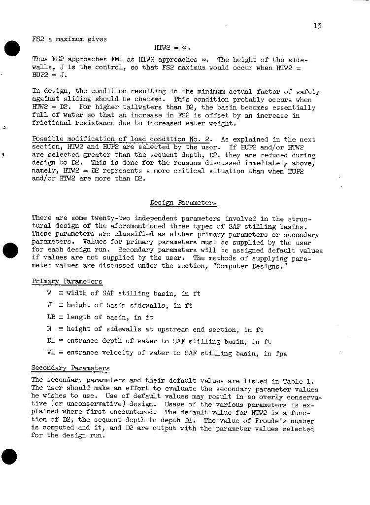
Flota t ion. -- Flo ta t ion analyses a r e e s s e n t i a l l y as described e a r l i e r . Figure 28 shows t h e various components of s l a b volumes, volumes of water on t h e slab, and u p l i f t volumes required t o perform t h e computations. TFUP, TPBG, and TPDN a r e each s e t i n i t i a l l y at 11 inohes. They a r e in- cremented as necessary t o obta in a s e t of values which s a t i s f y t h e f l o t a - t i o n c r i t e r i a . TPBG is incremented most quickly, TPDN is incremented n m t most quickly, and TFWP is incremented l e a s t quickly. If t h e c r i t e r i a remains unsat is f ied a f t e r 500 t r i d s , t h e design is abandoned.
Bearing pressures. -- The ana lys i s of bearing pressures i s s traightforward. It p a r a l l e l s t h e procedure described f o r type ( A ) basins except on a per foot width bas i s . A poss ib le case of LC #1 is i l l u s t r a t e d i n Figure 29. If t h e r e s u l t a n t v e r t i c a l force per foot i s VlKTC and t h e r e s u l t a n t moment about t h e moment cen te r 'in f t l b s per f t is M, and other quan t i t i e s a r e as previously defined, then
so, i n psf
PDN = PAVER (1 + ~E/LTOT)
PUP = PAVER (1 - ~E/LTOT)
If e i t h e r PUP o r PDN i s negative, corresponding s l a b thicknesses a r e in- cremented and t h e design is recycled. If e i t h e r RJP o r mlN exceeds t h e allowable bearing v d u e , t h e design i s abandoned.
Sl id ing. -- The pavement s l a b must s a t i s f y
CFSC 2 SLIDER FSLIDE
where, f o r LC #1
FSLIDE = FH1 - FT1
*ESrcept t h a t X may not exceed 40. f t .
(C) POSSIBLE UPLIFT, LC#1 OR LC#2.
(A) PAVEMENT SLAB THICKNESSES AND VOLUMES
(B) POSSIBLE WATER VOLUMES, L C # 1 AND LC#2.
Figure 28. Pavement slab components

and f o r LC #2
FSLIDE = FH2 + FM
Figure 29. Determination of pavement s l a b bearing pressvres, L C # ~
If t h e c r i t e r i a i s unsat is f ied a f t e r a trial, then TPUP, TPBG, and TPDN a r e equally incremented and another attempt i s made.
Longitudinal shear and bending. -- The pavement s l a b thickness a t any in- t e r i o r sec t ion may be governed by e i t h e r long i tud ina l shear o r bending moment. The thicknesses required by shear and moment a r e computed at a s e r i e s of sec t ions between t h e downstream end of t h e pavement s l a b and t h e break-in-grade, and a t another s e r i e s of sec t ions between t h e upstream end and t h e break-in-grade. If a t any sect ion t h e a c t u a l thickness i s l e s s than t h a t required f o r e i t h e r shear o r moment, t h e s l ab thicknesses a r e su i t ab ly incremented and t h e design Is recycled. The t o t a l number of pavement design t r i a l s , due t o any cause, i s a r b i t r a r i l y l imi ted t o 500.
Figure 30 indicates f o r LC #2, t h e load components used t o obta in shear, VP, i n l b s per f t , and moment, MP, i n f t l b s per f t a t a distance, XDN, i n f t from t h e downstream end of t h e s lab . From t h e sketch t h e water depth, HX, i n f t , i s
HX = m 2 - ( m 2 - ~ 1 ) x XDN/LB
and s l ab thickness, TX, i n inches, i s
t h e u p l i f t head, UX, i n f t , i s
UX = HUE + ~ ~ / 1 2
and t h e bearing pressure, PX, i n psf i s
PX = PDN - (PDN - RIP) x XDN/LTOT.

/ /
/ I
r HX
1- - - - - - - - I T X I _--- _----
TOEWALL h
u XDN I c\l
Y'
F TOP M P / 1 A--
Figure 30. Shear and moment i n pavement slab, xfi
For LC #2, t h e uniform loading, FTOP, i n l b s per ft per f t of width, ac t ing on t h e f l o o r of t h e basin i s
FTOP = FM/LB and
FBOT = ~ / L B + FTOP with these quan t i t i e s defined, VP and MP are r e ad i l y determined. The required thicknesses a r e taken as
TXV = Ivp1/840 + 3.5
m = (0.003683 x IMP^)^/^ + 3.5 These thicknesses a r e compared with t h e ac tua l thickness, TX, at t h e sect ion. Computations f o r a sect ion between the upstream end and t he break-in-grade are similar but somewhat more complex.
Retaining w a l l port ions. The design of t h e sidewall is t h e same as type ( A ) basins. However, t h e upstream end sect ion i s ve r t i c a l , hence as wi th type (B) basins
HS = J - N
LTOT = LS + LB

i n terms of HBW, HWW, CRJ, TW, and ARM. These moments a r e summed over t h e respect ive distances LB and LS t o obtain t h e t o t a l moment due t o l a t e r a l forces. SeveraJ. simplifying assumptions a re made t o obtain these
N
SECTION U
C TSDN
SECTION D
Figure 32. Retaining wall port ion l a t e r a l force moments, ~ # 2
moment expressions. A waterstop between t h e pavement s lab and t h e re ta in- ing w a l l base i s assumed e f fec t ive at t he elevation of t he bottom of t h e base slab. The thickness of t h e l e v e l base s lab i s taken a s TSDN i n these computations. The re ta in ing w a l l port ion is assumed t o bear against t he pavement s lab. NGAT, shown on t h e upstream section, is t h i s d i r ec t force. It i s t he force required f o r l a t e r a l equilibrium of t he section. Thus t he downstream sect ion working values, f o r t h e case shown a r e

The upstream s e c t i o n working vaJ.ues, f o r t h e case shown, a r e
ARM = T S D N / ~ ~ + XBG/ZS - TW/12
Working values f o r load condit ion No. 1 a r e s i m i l a r . With t h e working values known, t h e moments a r e read i ly expressed, t h e s m a t i o n s made, and t h e bearing pressures determined.
If any bearing pressure i s negative, t h e corresponding base s l a b th ick- ness and FTG are incremented. If any bearing pressure exceeds t h e allow- able, FTG i s incremented i n an attempt t o spread t h e t o t a l load.
Base s l ab shear and bending. -- Required base s l a b thicknesses w i l l some- times be governed by shear o r bending moment. Three cross sec t ions a r e checked: t h e downstream end sect ion, t h e sec t ion a t t h e break-in-grade, and t h e upstream end sect ion. Both load condit ions a r e inves t igated . Figure 33 shows t y p i c a l loadings. PBH and PBT a r e t h e bearing pres- sures at t h e hee l and t o e r e s u l t i n g from t h e preceding analyses of bearing. The o t h e r loadings a r e as defined - .
f o r type ( A ) basins. Shear and moment a r e computed a t the f a c e of P F t h e sidewall . Longitudi- n a l shears a r e t r e a t e d both ways as previously described. I f it i s as- P TS sumed ca r r i ed by t h e s ide- w a l l , shears and moments PU W a t t h e faces of t h e s ide- w a l l a r e unaffected by PBH PLONG. If t h e long i tud i - PB T
n a l shears a r e assumed ca r r i ed by t h e base s l a b Figure 33. Loadings f o r base s l a b then shear and moment
~ N G = (PIT + PBII)/P + mw - m - (PF x FPG + PIW x x ,- EWW)/WOB
and t h e face shear and moment expressions must include ULONG. The as - sumption leading t o t h e l a r g e r required thickness i s taken as control l ing . @ If any required thickness exceeds t h e a c t u a l s l a b thickness, t h e design i s recycled accordingly.

The wingwall i s considered t o a c t e s s en t i a l l y independently of t he basin proper. The wingwall is v e r t i c a l and of constant thickness. It i s a r t i cu l a t ed from the basin sidewall a s shown i n t he layout drawing of Figure 4. The wingwall footing and toewall a r e monolithic with t he foot- ing and toewall of t h e basin proper. Design invest igat ions include bend- ing of t h e wingwall and wingwall footing, overturning, and s l id ing . Fig- ure 34 shows t he wingwall sect ion assumed f o r design. The toewall below
I
EARTH LINE I l I --TOE WAL L NEGLECTED I , IN DESIGN
Figure 34. Wingwall design sect ion
t h e foot ing i s assumed non-existent. The ea r th l i n e i n f ron t of t h e wingwall is hor izonta l a t the elevation of t he bottom of t h e footing. The e a r t h f i l l slopes a t t h e back of t he w a l l a r e defined below.
The sidewall and wingwall a re shown as l i n e diagram idea l i za t ions i n Figure 35. E a r t h f i l l surfaces a r e a l s o shown. The surface of t h e earth- f i l l against t he wingwall va r ies l i n e a r l y from HB at t he a r t i cu l a t i on jo in t t o 1 .0 f t above the top of t he foot ing a t t he downstream end of the wingwall. These surfaces give r i s e t o th ree slope parameters of i n t e r e s t , they a r e
ZPS z slope parameter f o r t he e a r t h f i l l adjacent t o t h e sidewall i n t h e d i rec t ion p a r a l l e l t o t h e sidewall
ZNW z slope parameter f o r the e a r t h f i l l adjacent t o t h e wingwall i n t h e d i rec t ion normal t o t he wingwall
ZNS - slope parameter f o r t h e e a r t h f i l l adjacent t o t he sidewall i n t he d i rec t ion normal t o t he wingwall.
Thus,

SIDE WALL
PARTIAL PLAN
PARTIAL ELEVATION +-I Figure 35. Wingwall e a r t h f i l l surfaces and slopes
The e a r t h f i l l height, YB, i n f t above t h e top of t h e foot ing f o r any d i s - tance, X, i n f t from t h e a r t i c u l a t i o n jo in t is
YB = HB - X/ZNW.
With t h e sloping e a r t h f i l l shown i n Figure 34, a b r i e f might be presen- t e d f o r assuming t h a t l a t e r a l e a r t h pressures a r e inc l ined from t h e hor i - zontal . That is, they have v e r t i c a l and hor izonta l components. This is not done herein. La te ra l e a r t h pressures a r e hor izonta l and vary d i r e c t l y wi th KO and dis tance below t h e surface. To include a v e r t i c a l component would be unconservative s ince it would be a s t a b i l i z i n g fo rce ( i n over- turning and s l i d i n g analyses) whose existence and magnitude a r e uncertain.
Loading conditions. Wingwall design requires t h e inves t igat ion of more than t h e two load conditions necessary f o r t h e d e s i m of t h e bas in proper. C r i t i c a l loading of ten occurs a t an intermediate load condition between

LC #1 and LC #2. Furthermore, d i f f e r e n t load condit ions m e c r i t i c a l f o r d i f f e r e n t functions. Therefore, a s shown schematically i n Figure 36,
SECTION AT X l+ Figure 36. Load condit ions f o r wingwall design
two intermediate load conditions a r e created f o r use i n design of wingwalls. These a r e ILC #1 and ILC #2. The construction condition, CC, with no water e i t h e r s ide of t h e wingwdll, is included as s t i l l another loading s ince it w i l l sometimes con t ro l a function. For LC #2 the water surface both s ides of t h e w a l l i s W 2 above t h e top of t h e foot ing. Let
HW - u p l i f t head above top of foot ing at t h e a r t i c u l a t i o n jo in t , f o r t h e load condition under inves t igat ion, i n f t
IN = t a i l w a t e r depth above top of foot ing f o r t h e load condition under inves t igat ion, i n f t .
Then t h e water height, YW, i n f t on t h e back face of t h e wingwall f o r any distance, X, i s
YW = - (HW - U W ) x X/(J - M)

when X < (5 - DW) . It is
when X 2 ( J - DW).
The water depth on t h e f r o n t f ace of t h e w a l l i s constant a t IN. Water surfaces a r e assumed hor izonta l normal t o t h e wingwall.
Winmall bending. The thickness of t h e wingwall i s determined by shear o r moment and d i r e c t fo rce a t t h e bottom of t h e w a l l a t t h e sec t ion ad- jacent t o t h e a r t i c u l a t i o n jo in t . All load condit ions indicated i n Fig- ure 36, except LC #2, a r e inves t igated t o obtain t h e maximum required thickness. Load condit ion No. 2 cannot produce m a x i m u m shear o r moment a t t h e base of t h e sec t ion. Figure 37 i l l u s t r a t e s a poss ib le case f o r one load condition.
Figure 37. Determination of wingwall thickness
The thickness required by shear is determined d i r e c t l y . The thickness required by moment and d i r e c t fo rce i s determined by an i t e r a t i v e process. The shear is, i n l b s per f t
so t h e required thickness f o r shear i s , i n inches
TS = ~/840 + 2.5
The moment is, i n f t l b s per ft
M = 10.4(@ - D$) + 0.5 x KO x GB x @/3.
The d i r e c t force f o r a thickness, TM, i s
N = 12.5 x J x 'I'M
so t h e equivalent moment i s
M, = M + N x (0.5 x m - 2.5)/12
and t h e required thickness f o r moment and d i r e c t fo rce is, i n inches
TM = (0.003685 x M , ) ' / ~ + 2.5
The computed required TM and t h e assumed TM must agree.

These computations a re repeated f o r t he four load conditions. The wing- w a l l thickness, TWW, i s t h e l a r g e s t of all of t h e above required th ick- nesses.
Overturning. I n i t i a l values of wingwall footing projections, BUP and BDN, a r e determined by considering the wingwall a s an independent w a l l and making it s t ab l e against overturning. Required footing projections a r e determined by analyzing s l i c e s of uni t width a t t h e four sections indicated by Figure 38. Each s l i c e must be s tab le by i t s e l f . Individ- u d s l i c e s a r e analyzed, ra ther than t h e e n t i r e wingwall a s a uni t , be- cause of t h e complexity of t r e a t i ng general bearing on an unsymmetrical bearing area.
Figure 38. Wingwall footing projections
The required footing projections a r e found at each of t he four sections. Then BUP and BDN a r e selected from t h e requirement t h a t footing pro- jections vary l i n e a r l y between BUP and BDN. I f any required projection a t sect ions 2, 3, o r 4 exceeds t h e required projection a t sect ion 1, the projection f o r t he e n t i r e footing is made constant at t he l a rge s t required value. Each sect ion i s investigated f o r a l l load conditions shown i n Figure 36 t o obtain t he maximum required projection a t t h e sec- t ion . Figure 39 indicates t h e analysis f o r a poss ible case at a p a r t i - cular sect ion and load condition. The dis tance from the section under consideration t o t h e wingwall a r t i cu l a t i on jo int is X. X is a l so t h e distance from t h e back of t h e w a l l t o t h e break i n e a r t h f i l l slopes. Current values of footing t h i c f i e s s , TWF, and footing projection, liTG, a r e investigated. F i r s t trial. values are TWF = TWW and FTG = l . Foot- ing pressures, l a t e r a l water and ea r th pressures, u p l i f t pressures, footing dead load, and w d l weight a r e determined f o r the current values. Footing pressures vary l i n e a r l y between t h e th ree points: back of t h e w a l l , X from the w a l l , and edge of footing.
With t h e loads known, moments about t h e t o e and summation of v e r t i c a l forces loca tes VTET at Z f r o m t he toe. If VNET i s located outs ide t h e base width, WOB, t ha t is Z i s negative, then FTG i s incremented f o r another trial. If VJlEF i s located within t h e base, within W O B / ~ of t h e toe, then PBH would be negative s:, again FTG is incremented f o r another
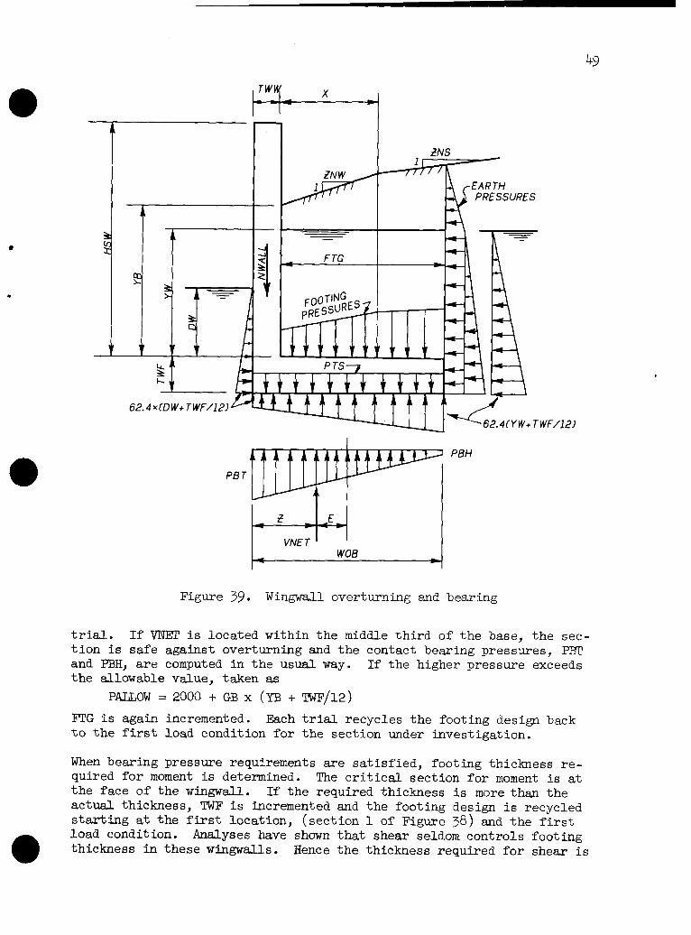
PBH
PB T
Figure 39. Wingwall overturning and bearing
t r ia l . If VNEZC i s located within t he middle t h i r d of t he base, t h e sec- t i o n i s s a f e against overturning and t h e contact bearing pressures, PBT and PBH, a r e computed i n t h e usua,l way. If the higher pressure exceeds t he allowable value, taken as
P U O W = 2000 + GB x (YB + TWF/12)
FTG i s again incremented. Each trial recycles t h e footing design back t o t h e first load condition f o r t h e section under investigation.
When bearing pressure requirements a re s a t i s f i ed , footing thickness r e - quired f o r moment is determined. The c r i t i c a l sect ion f o r moment is at t he face of t he w i n g w a l l . I f t he required thickness i s more than t he ac tua l thickness, TWF i s incremented and t he footing design i s recycled s t a r t i n g a t t he f i r s t location, (sect ion 1 of Figure 38) and t h e f i r s t load condition. Ana.lyses have shown t h a t shear seldom controls footing thickness i n these wingwalls. Hence t h e thickness required fo r shear i s

only checked, and t h e design recycled if necessary, i n d e t a i l design.
slid in^. The basin proper is designed t o s a t i s f y longi tudinal s l i d ing requirements, by i t s e l f . Therefore, no addi t ional s l i d i n g force should be brought t o t h e basin by t he wingwalls. This means the wingwalls should be adequate themselves t o r e s i s t s l id ing i n t he longi tudinal d i rec t ion of t he basin. (Any tendency of t h e wingwall t o s l i d e i n a transverse di rect ion, toward t h e center of the channel, is r e s i s t ed by t h e wingwall-to-basin t i e discussed i n t h e next sect ion. ) Let t h e r e - su l t an t horizontal driving force normal t o t h e sidewall be FSLIDE, see Figure 40. This force i s obtained by summing, over t h e length of t he sidewall, t h e net hor izontal forces per uni t length, HNET, at each of
HNE T f---
Figure 40. Longitudinal s l i d ing of wingwall
t h e four sections. HNET i s obtained from t h e indicated hor izontal forces, f o r a pa r t i cu l a r sect ion and Load condition. Thus
Similarly, i f VWING i s t he resu l tan t v e r t i c a l force on t he wingwall, and TNET i s t he resu l tan t per un i t length, then

The longi tudinal component s i s t s l id ing, t h e w i n g w a l l
1.4142 x WING x CFSC FSLIDE
f o r each load condit ion of
of FSLIDE i s FSLIDEIQ. To adequately r e - must s a t i s f y t he r e l a t i on
2 SLIDER
Figure 36.
If the above r e l a t i on is not s a t i s f i e d f o r any load condition, BUP and BDN a r e incremented equally. The design i s recycled t o t he start of t h e overturning analys is with the new foot ing project ion values. This i s necessary because t h e wingwall footing thickness, TWF, may require incrementing with t he l a r g e r foot ing project ions .
Wingwall-to-basin t i e . A s t r u c t u r a l t i e i s provided between t he wing- w a l l foot ing and t he foot ing and f l o o r s l ab of t h e bas in proper. This wingwaJl-to-basin t i e prevents r o t a t i on of t h e w i n g w a l l about i ts junc- t i o n with t h e bas in sidewall and thus e f fec t ive ly prevents any poss ib i l - i t y of t ransverse s l i d ing of t h e wingwall. The wingwall-to-basin t i e is designed f o r t h e f u l l moment due t o t he r e su l t an t hor izonta l force, FSLJDE, of Figure 40. This i s admittedly conservative in t h a t it com- p l e t e ly neglects any f r i c t i o n a l r es i s t ance t h a t i s developed. Let MTI3 be t h e full moment, i n foot l b s , and ARM be t h e moment arm. shown i n Figure 41. Then, i n inches
\\ ,-6"TO C.G. OF
Figure 41. Wingwall-to-basin t i e s t e e l a r ea
and t h e required a rea of t h e t i e s t e e l , In sq. in., jus t downstream of t h e sect ion through the a r t i c u l a t i o n jo int i s approximately


D e t a i l - Designs - With t h e two except ions of t h e l o n g i t u d i n a l s t e e l i n t h e pavement s l a b o f t ype ( c ) s t i l l i n g bas ins and t h e wingwall-to-basin t i e s t e e l , d e t a i l design i s concerned w i t h t h e de te rmina t ion of requirements f o r t r a n s v e r s e s t e e l . Transverse s t e e l i n t h e pavement s l a b and l o n g i t u d i n a l s t e e l i n a l l o t h e r elements need only s a t i s f y temperature and shrinkage (T and S ) requirements .
Each d e t a i l design begins w i t h t h e s e t o f t r i a l dimensions obtained i n t h e pre l iminary des ign . Thicknesses a r e incremented, and t h e design r e - cycled, whenever it i s discovered compression s t e e l would otherwise be requi red t o hold bending s t r e s s e s t o al lowable working va lues . A wing- w a l l d e t a i l design accompanies t h e d e t a i l design of every bas in reques ted . . Required s t e e l a r e a and maximum al lowable s t e e l spacing a r e computed a t a s u f f i c i e n t number of p o i n t s t o adequate ly d e f i n e t h e s t e e l requirements of t h e s t i l l i n g bas in . S t e e l a r e a s given always s a t i s f y T and S r equ i r e - ments. I n t h e s idewal l , t h e p o i n t s a r e t h e same f o r each s t i l l i n g bas in type . I n t h e f l o o r s l a b s of types (A) and (B) bas ins and i n t h e base s l a b of t ype ( c ) bas ins , t h e p o i n t s a r e s i m i l a r l y l oca t ed and numbered so t h a t t h e r e i s l i t t l e d i f f i c u l t y i n switching thought from one type t o another . Schematic s t e e l l a y o u t s a r e shown f o r s idewal l s , f l o o r and base s l abs , and wingwalls. The a c t u a l s t e e l i s s e l e c t e d by t h e des igner once he knows t h e s t e e l requirements a t t h e va r ious p o i n t s .
Sidewall s t e e l
S t e e l a r e a s and spacings a r e determined f o r t h e e l e v e n p o i n t s def ined i n Figure 42. Points 1 through 1 0 a r e on t h e i n c l i n e d s t e e l i n t h e back of t h e wa l l . The v e r t i c a l s t e e l i n t h e f r o n t of t h e w a l l need only be provided i n T and S amounts w i th t h e p o s s i b l e except ion of s t e e l i n t h e v i c i n i t y o f po in t 0, discussed l a t e r .
Refer t o F igures 1 4 and 42. Study of ske t ch ( A ) o f Figure 1 4 shows t h a t f o r LC #1 t h e s t e e l requirement a t p o i n t s 2, 3, 4, o r 5 equals o r exceeds t h e ~ t e e l requirement a t any p o i n t t o t h e r i g h t of, and a t t h e same e leva- t i o n a s , t h e po in t under cons idera t ion . Observation of ske t ch (B) o f Fig- u re 1 4 f o r LC #2 shows t h a t s i m i l a r s ta tements apply if t h e water depth, D l , i n t h e b a s i n is neglected f o r p o i n t s 2, 3, and 4.
The s t e e l requirements f o r t h e v e r t i c a l s t e e l i n t h e back f a c e of t h e s idewa l l a r e t h e r e f o r e eva lua ted a s fo l lows . The requirements a t p o i n t s 1 through 5 and a t corresponding p o i n t s 6 through 1 0 a t t h e break-in- grade s e c t i o n a r e determined. Note t h a t it i s o f t e n convenient o r neces- s a r y t o a l t e r t h e w a l l s t e e l l ayou t a t t h e break-in-grade s e c t i o n . The s t e e l determined f o r po in t 3 i s adequate between p o i n t 3 and po in t 8. The s t e e l determined f o r po in t 8 is adequate between po in t 8 and t h e po in t on t h e downstream end s e c t i o n a t t h e same e l e v a t i o n as po in t 8. Corresponding s tatements a r e t r u e f o r s i m i l a r p a i r s of p o i n t s . The s t e e l r e q u i r e d . a t po in t 5 i s repor ted f o r purposes o f i n t e r p o l a t i o n . Any i n t e r p o l a t i o n should assume s t r a i g h t - l i n e v a r i a t i o n between p o i n t s . For t ype (B) bas ins , t h e th icknesses of t h e upstream por t ion a r e used w i t h p o i n t s 1 through 5 whereas t h e th icknesses of t h e downstream p o r t i o n a r e used w i t h p o i n t s 6 through 10 . For types ( A ) and ( c ) bas ins , t h e s e t h i c k -

SECTION
Figure 42. Sidewall s t e e l layout and po in t loca t ions
nesses a r e t h e same so po in t s 5 and 1 0 a r e a c t u a l l y t h e same po in t .
Figure 43 i l l u s t r a t e s a poss ib le loading s i t u a t i o n . It might be LC #1 o r LC #@. The sec t ion under cons idera t ion is located a t d is tance , Z,

Figure 43. Sidewall s t e e l design
from t h e top of t h e w a l l . Shear, VZ, i n l b s per f t ; moment, MZ, i n f t l b s per ft; and d i r e c t force, NZ, i n l b s per ft a r e determined f o r t h e sec t ion and loads. The required s t e e l a r e a f o r t h i s MZ and NZ may be obtained as explained i n TR-42. If t h e current e f f e c t i v e depth i s inadequate without using compression s t e e l , t h e bottom thickness, TBV, and hence TB, is incremented and t h e w a l l s t e e l design is begun again. When t h e e f f e c t i v e depth i s adequate, t h e maximum allowable spacing of t h e s t e e l at t h i s sec t ion is given, i n inches, by
as explained on page 47 of TR-42.
A s noted e a r l i e r , t h e water surface on t h e outs ide of t h e basin s ide- w a l l s , f o r LC @, is taken conservatively a t FlW2 f o r sidewall bending analyses. However, when HlW2 > HUE, tens ion may occur i n t h e s t e e l i n t h e f r o n t of t h e w a l l at and i n t h e v i c i n i t y of point 0 on t h e assumption t h e water surface on t h e outs ide of t h e w a l l i s at H U E . Therefore a s t e e l requirement i s reported f o r point 0 only when HTW2 > H U E and ten- s ion i s computed t o e x i s t at t h i s sec t ion with
HBZ = HB

5 6 Floor s l ab s t e e l
S tee l areas and spacings a r e determined at twelve points i n t he f l o o r s l ab i n each of th ree sect ions f o r type ( A ) basins and i n each of four sections f o r type (B) basins. Both LC #1 and LC #2 a r e investigated. The th ree type ( A ) basin sect ions a r e the downstream end section, t he break-in-grade section, and t he upstream end sect ion. The four type ( B ) basin sect ions a r e t he downstream end section, a sect ion imrnediate- l y downstream of t h e break-in-grade, a section immediately upstream of t h e break-in-grade, and t h e upstream end section. The toewall is neg- l ec ted i n computing t h e downstream end sect ion s t e e l requirements. Figure 44 gives t he loca t ion and numbering of t he twelve points i n each
. . sect ion.
f
I W / 4 I W / 4 TYPElBl UPSTREAM POR TlON
DOWNSTREAM PORTION
UPSTREAM END
UPSTREAM OF B- I-G DOWNSTREAM OF B- I -G
DOWNSTREAM END
DOWNSTREAM DOWNSTREAM
END OF 8 - I - G
4 2 4 0 3 8 3 6 UPSTREAM OF B- I -G
5 4 52 5 0 4 8 UPSTREAM END
NOTE:
FOR TYPEIA) POINTS 35-46 ARE OMITTED AND POINTS 23-34
ARE AT BREAK-IN-GRADE SECTION.
Figure 44. Floor s l ab s t e e l layout and point locat ions
In accordance with previous discussion, see page 26, bearing pressures a r e assumed constant along any t ransverse sect ion of t h e basin. Fig- ure 22 shows loads and per t inent var iables involved. For t h e case shown, t he d i r ec t compressive force in t h e foot ing projections, i n l b s per ft, i s
CF = (KO x GM x HDlFF + (KO x GB + 62.4)(~~~ + ~ ~ / 2 4 ) ) x ~ ~ / 1 2
where HDIFF = KBW - HUW. The hor izonta l loading on t he wall i s
IWALL = KO x GM x HDlFF x (HDIFF'/~ + HUW)
+ KO x GB x HW2/2 + 62.4(HUW2 - DW2)/2.
Thus t h e d i r ec t compressive force i n t h e f l o o r s l ab between t h e s ide- w a l l s , i n l b s per ft, i s

Shear and moment values at any locat ion are a l so computed d i r ec t l y by s t a t i c s . Longitudinal. shear is t r ea t ed both ways described on pages 28 and 29.
With moment and d i r ec t force, and shear known at any location, required s t e e l a rea and maximum s t e e l spacing may be evaluated as explained i n TR-42. The e f fec t ive depth i s (TS-3.5) f o r pos i t ive moment, t h a t i s , moment producing tension i n t he bottom of t h e slab, and (TS-2.5) for negative moment. I f t h e e f fec t ive depth i s inadequate, t he s lab th ick- ness i s incremented and t h e f l oo r s lab s t e e l design i s begun again. For negative moment, a check i s made t o determine i f t h e top s t e e l quali- f i e s as "top bars" with regard t o spacing of s t e e l f o r bond. The spac- ing of "top bars" i s given by S = 7093 x ( T - 2. ~)/vz i n accordance with TR-42.
Base s lab s t e e l
S tee l areas and spacings a r e determined at twelve points i n t h e r e t a in - ing w a l l base i n each of th ree sections f o r type ( c ) basins. The sec- t i ons a r e the downstream end section, t h e break-in-grade section, and t h e upstream end section. Figure 45 gives t he locat ion and numbering of t h e points.
UPSTREAM END
BREAK-IN-GRADE DOWNS TRFAM END
DOWNSTREAM END
BREAK-IN-GRADE
UPS TREAM END
Figure 45. Base s lab s t e e l layout and point locat ions
Bearing pressures a t the toe and heel of t h e upstream and downstream end sections a r e obtained as described f o r preliminary design of t ype ( c ) re- t a in ing w a l l portions. Bearing pressures at t h e break-in-grade section a r e obtained by in terpola t ion. Shear and moment values at any locat ion i n t h e t o e and heel of any sect ion a r e computed by s t a t i c s . Figure 33 shows t h e v e r t i c a l loads involved. Direct compressive forces i n footing projections and i n t h e t oe s lab a r e computed a s indicated above f o r f l oo r s lab s t e e l . With the force system at a locat ion known, s t e e l re- quirements a r e read i ly ascertained. Longitudinal shear is again t rea ted both ways.

5 8 Pavement s lab s t e e l
Longitudinal s t e e l areas and spacings a r e determined a t the t en points i n t h e pavement s lab shown i n Figure 46. She= and moment values f o r these locat ions a r e obtained during preliminary design a t t he same time s lab thicknesses are checked throughout t h e s lab f o r longi tudinal shear and moment. Both LC #l and LC #2 a re investigated t o obtain maxi- mum requirements.
Figure 46. Pavement s l ab s t e e l layout and point locat ions
Wingwall s t e e l
S t ee l areas and spacings a r e determined at s i x points i n each of th ree sect ions in the wingwal l . Figure 47 gives t h e locat ion of t he sect ions and numbering of t he points. The sect ions axe adjacent t o t h e a r t i cu - l a t i o n jo int and at t h e i n t e r i o r t h i r d points of t he wingwall span. Figure 48 gives t h e wingwall sect ion s t e e l layout and locates t h e s i x points where s t e e l requirements a r e evaluated.
There a r e two l i n e s of pr incipal s t e e l i n a wingwall sect ion. These l i n e s axe t h e v e r t i c a l s t e e l i n t h e back face of t he wingwall and t h e top s t e e l i n t he wingwall footing. Detail ing must ensure t h a t ade- quate anchorage i s provided these two l i n e s at t h e junction of wing- w a l l and wingwall footing. All other s t e e l i n t he sect ion i s required
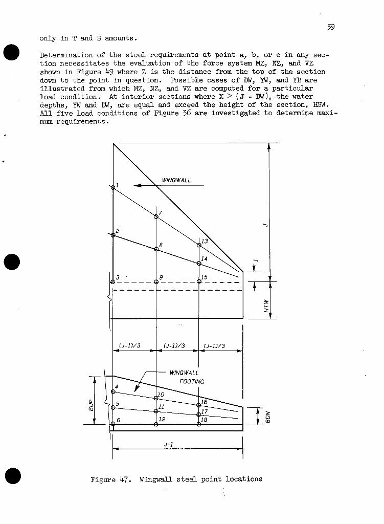
59 only i n T and S amounts.
Determination of t h e s t e e l requirements a t point a, b, o r c i n any sec- t i o n necess i t a t es t h e evaluation of t h e fo rce system MZ, NZ, and VZ shown i n Figure 49 where Z i s t h e d is tance from t h e t o p of the sec t ion down t o t h e point i n question. Possible cases of DW, YW, and YB a r e i l l u s t r a t e d from which MZ, NZ, and VZ a r e computed f o r a p a r t i c u l a r load condit ion. A t i n t e r i o r sec t ions where X > ( J - DW), t h e water depths, YW and IN, a r e equal and exceed t h e height of t h e sect ion, HSW. A l l f i v e load conditions of Figure 36 a r e inves t igated t o determine maxi- mum requirements.
WlNG W A L L
& WING WA L L I
Figure 47. Wingwall s t e e l point loca t ions - --

Figure 48. Wingwall sec t ion s t e e l layout
Determination of t h e s t e e l requirements a t point d, e, o r f s imi la r ly necess i t a tes t he evaluation of t he fo rce system MZ, NZ, and VZ shown in Figure 50 where Z i s t h e dis tance from the edge of the foot ing pro- jec t ion t o t he point i n question. Sketch (A) shows a poss ible combina- t i o n of YB, YW, and DW. Sketch ( B ) shows t h e r e su l t i ng loadings and bearing pressures and indicates t h e sumnation t o obtain MZ and VZ. The d i r e c t compressive force, NZ, i s obtained as suggested by t h e next two sketches. Sketch ( c ) defines t h e r e su l t an t hor izonta l forces involved. Sketch ( D ) puts t h e sect ion i n hor izonta l equilibrium using t h e resu l t an t hor izonta l forces and indicates the summation t o obta in NZ. A l l f i v e load conditions of Figure 36 a r e investigated .
-
The wingwall foot ing thickness required f o r shear is checked during these computations. Maximum shear i n t h e foot ing can o c c u a t the face of t h e w a l l o r a t some i n t e r i o r locat ion. Shear seldom controls th ick- ness. When it does, t he thickness i s incremented and t h e foot ing s t e e l design i s begun again.
I
FTG - -
- - - , f
A
P Y
a Y
(?
2 Y
b r
FTG/3
C
y I
1 1 --I
1 2 FTG/3 FTG/3 -
e
-
d

Figure 49. Determination of the force system at a point in wingwall

r- WOB
FTG PRESS.
FTG DEAD
UPLIFT
BEARING CHl+H2-H41 A 1
WOB
Figure 50. Determination of the f o r c e system in wingwal l foo t ing

Concrete Volumes
Concrete volumes, i n cubic yards, a r e computed f o r both preliminary and d e t a i l designs. The volumes a r e given i n two pa r t s . The f i r s t i s t he volume of t h e basin proper, exclusive of wingwalls. The second i s t he volume of t h e wingwalls including severa l adjustments. These adjus t - ments account f o r t he mating of ( 1 ) sidewall t o wingwall, ( 2 ) basin and wingwall toewalls, and (3) basin and wingwall footings.
Basin Volumes
The basin volume of each type of SAF s t i l l i n g basin is read i ly obtained. Certain assumptions a r e made t o f a c i l i t a t e computing t h i s volume. It is assumed t h a t t he sidewalls end abruptly at the downstream end sect ion. It i s fu r t he r assumed t h a t t h e basin toewall ends abruptly a t t h e outer edges of t he sidewall, t h a t is, t he toewall does not extend under t h e basin foot ing projections.
The basin volume f o r type ( A ) o u t l e t s is obtained by pa r t i t i on ing t he sidewalls and f l oo r s l ab as shown by Figure 17. Component so l ids a r e prismatoids f o r which the volume i n general is
V = ( A ~ + 4& + A2)h/6
where A, = a r ea of r i g h t sec t ion at one end of so l i d
A a r ea of r i g h t sect ion at other end of so l i d ?
A, = a r ea of mid-section of so l i d
h = perpendicular d is tance between r i gh t end sections.
The basin volume f o r a type (B) basin is obtained i n accordance wi th t h e pa r t i t i on ing shown by Figure 24. Similarly, t h e volume of the re ta in ing w a l l port ion of a type ( c ) basin i s a l s o obtained i n accordance with Fig- ure 24, but with f l oo r s l ab thickness of TSBG at t he break-in-grade. The pavement s l ab volume of a type ( c ) basin follows from Figure 28, sketch (A) . In ca lcula t ing these volumes, t h e overa l l widths of the basin a r e taken as
f o r type (A) , and a l s o f o r type (c) , but with W taken as 2X. Type ( B ) widths a r e
WOU = W + 2 ( T B W / ~ ~ + FTGU) WOD = W + ~ ( T B v D / ~ ~ + FI'GD).
It should be noted t he basin volumes do not include volumes of chute blocks, f l oo r blocks, end s i l l s , f i l l e t s on toewalls, o r upstream f l o o r jo in t s teps . It i s assumed t h a t chute blocks, f l oo r blocks, and end s i l l s a r e dimensioned during hydraulic design and t h a t they a r e subject t o some shape and/or s i z e va r ia t ion . Likewise, f i l l e t s i z e and jo in t s t ep d e t a i l s a r e subject t o va r ia t ion depending on designer preference.
Wingwall Volumes
The computation of t h e wingwall volume with i t s adjustments is somewhat complicated. Figure 4 shows a t yp i ca l wingwall layout. F i r s t t h e wing-

wal l volume i s computed without adjustments. As with the basin proper, ce r ta in assumptions a r e made t o f a c i l i t a t e computing t h i s volume. It i s assumed t h a t t he wingwall and wingwall toewall begin a t t he a r t i cu- l a t i o n jo int and extend outward a span of (3-1). It i s fu r ther assumed t h a t t h e basin proper i s without footing projections. The wingwall vol- ume without adjustments, VWOAD, thus consis ts of the volumes of ( 1 ) t h e wingwall, ( 2 ) t h e wingwall toewall, and ( 3 ) t h e wingwall footing with i t s extension back t o t h e basin sidewall. Figure 51 del ineates these volumes.
I
I LEVEL
Figure 51. Wingwall volume without adjustments
The adjustments subsequently applied t o t he wingwall volume depend on t h e corner d e t a i l shown i n Figures 4 and 51. The c o r w r d e t a i l i s shown t o l a rge r scale i n Figure 52. The thickness 09 the wingwall toe- w a l l , 'IWT, i s t he l a rge r of t h e thickness of t h e b m i n toewall, TTW, o r t he thickness of t h e wingwall, TWW. The l e v e l disjtance, LEYEL, which loca tes t he a r t i cu l a t i on jo int with respect t o t& corner of t h e side- w a l l , and t h e distance, MCK, which serves t o *fine t h e wingwall foot- ing extension back t o t he sidewall, a r e given i n inches by
LEVEL = TBV/J~
BACK = TWT - LENEL
otherwise LEVEL = TBV x J2 - TWW BACK = TWT - TWW

The former case i s i l l u s t r a t e d Figure 52. The l a t t e r case i s sketch of Figure 52.
65 by Figure 51 and t he upper sketch o f i l l u s t r a t e d by Figure 4 and t h e lower
t TBB
'TICUL A TlON
JOINT
Figure 52. Corner de t a i l , wingwall-to-sidewall

Sidewall s tub adjustment. Instead of t h e sidewall ending abruptly a t the downstream end sect ion, t h e sidewall makes a 45' t u r n and ends at t h e a r t i c u l a t i o n jo in t a s i s shown i n Figure 52. Thus a volume correc- t i o n o r adjustment is necessary. Adjustments a re applied herein t o t h e wingwall volume so t h a t r e l a t i v e volumes of d i f f e r e n t types of? basins may be d i r e c t l y compared with more meaning. The sidewall s tub ad jus t - ment volume, WALL, i s t h e d i f ference between t h e sidewall volumes when t h e sidewall ends a t the a r t i c u l a t i o n jo in t and when t h e sidewall ends a t t h e downstream end sect ion.
Toewall s tub adjustment. Instead of t h e bas in toewall ending a t t h e outer edges of t h e sidewall, t h e basin toewall mates wi th the wingwall toewall i n a 45' tu rn a s i s shown i n Figure 52. Thus another volume ad- justment i s required. The toewall s tub ad justment volume, VTOE, i s t h e d i f ference between t h e volume of t h e basin toewall mated t o t h e wing- w a l l t o e w d l ( t h e toewall taken t o t h e plane of t h e a r t i c u l a t i o n j o i n t ) and t h e volume of t h e bas in toewall ending a t t h e outer edge of t h e s ide- w a l l .
Basin foot ing adjustment. Usually t h e basin proper w i l l have foot ings . Such footings extend t o t h e downstream end sect ion. Thus an adjustment is necessary t h a t w i l l t ake account of any wingwall foot ing t h a t i s i n space already occupied by the basin footing. Several configurat ions a r e poss ib le depending on the r e l a t i v e values of t h e basin foot ing pro- ject ion, FTG, vs t h e wingwall var iables , WTWT, WEXT, WDES, and W P R O J shown i n Figure 53. Sketch ( A ) i l l u s t r a t e s these va r iab les and a l s o t h e distance, WWLB. This is t h e d is tance from t h e plane of t h e down- stream end sec t ion upstream t o t h e point where t h e wingwall foot ing ex- tended backward would i n t e r s e c t t h e outer edge of t h e sidewall . The wingwall var iables , i n f e e t , a r e
WPROJ = BACK/^^ + ( J - 1) + (BDN - (TWT - T W W ) / ~ ~ ) ) / J ~
WWLB = (BUP - (TBV/,[~ - ~ ) / 1 2 ) J2
Sketches ( B ) through ( E ) of Figure 53 ind ica te by shaded area, t h e bas in foot ing adjustment volume t h a t must be deducted from t h e wingwall volume without adjustment . Sketch ( E ) shows a r a r e but poss ib le case where a volume indicated by t h e l ined a r e a must be added t o t h e wingwall volume without adjustment. The basin foot ing adjustment volume, VFTG, i s com- puted using t h e w i n g w a l l foot ing thickness, TWF. Let
VWmG = WOAD + WALL + WOE
then, t h e adjusted wingwall volume i s
QUANT = VWING - VFTG.
If f o r any reason VFTG can not be computed, QUAKC i s s e t t o zero and a message i s given. For example, VFTG i s not computed when (WWLB - LB) > FTG. This does not mean t h e design i s unsat is fac tory . Rather, it means t h a t some design decision is necessary concerning t h e layout of t h e wingwall footing.

PLANE OF DOWNSTREAM
END SECTION
WWLB
[E l WDES<FTG<WPROJ
Figure 53. Basin-wingwall foot ing poss ib i l i t ies

Computer Designs
Input
Two l i n e s of alphameric information must preceed a l l o ther d a t a i n t h e input f o r a computer job. A given computer job may include many design runs. From one t o f i v e l i n e s of input d a t a a r e required f o r each design run. A dez5.gn run is made f o r a p a r t i c u l a r s e t of design condit ions and takes one of two forms. The f irst form cons i s t s of t h r e e prelimin- a ry designs, one f o r each S U s t i l l i n g basin type, p lus a preliminary design of t h e wingwalls. The second form cons i s t s of t h e d e t a i l de- s ign of one of t h e bas in types plus a d e t a i l design of t h e wingwalls.
The input da ta provided per design run cons i s t s e s s e n t i a l l y of values f o r t h e primary design parameters and, if desired, values f o r t h e secon- dary parameters. Table 2 shows t h e l i n e s t h a t m y be provided per run together with t h e s p e c i f i c design parameters contained on t h e f i r s t and l a s t t h r e e l i n e s .
Table 2. Input values per design run
DFALTl
HB
MAXFTG
The f i rs t l i n e contains t h e primary parameters, W, J, LB, N, D l , and V1 and i s always required. If DESIGN = 0, t h e t h r e e prel iminary designs a r e performed. If DESIGN =1, 2, o r 3, t h e d e t a i l design of SAF type (A) , ( B ) , o r ( c ) i s performed. If DFALTS = 0, all secondary parameters a r e assigned de fau l t values and t h e next four l i n e s must be omitted. If DFALTS > 0, some o r a l l secondary parameters a r e assigned user values and t h e next l i n e of input d a t a must be provided.
GM
If DFALTl = 0, t h e l i n e of input d a t a s t a r t i n g with HB must be omitted. I f DFALTl > 0, t h e l i n e of input d a t a containing values of HB through HUPl must be provided.
DFALT2
H T W ~
FLOATR
If DFALT2 = 0, t h e l i n e of input d a t a s t a r t i n g wi th MAXrmG must be omit- ted . If DFALT2 > 0, t h e l i n e of input da ta containing values of MAXFTG through BAT must be provided. Simi lar ly f o r DFALT3 and t h e l i n e of in- put d a t a s t a r t i n g wi th GM.
GS
Thus t h e number of l i n e s of d a t a t h a t must be provided per design run w i l l vary depending on whether t h e de fau l t values are acceptable o r whether t h e user wishes t o supply c e r t a i n secondary parameter values. Note t h a t although various l i n e s m y be omitted, those supplied must be complete and i n t h e order indicated.
DFALTS
HUE
SLIDIZR
KO
-
HTWl
ZS
CFSC
-
HUPl
BAT
- - -
1
- HTW
- -
-
-1 TIW
- - -

The two l i n e s of alphameric data a r e used t o provide information such a s s i t e number, watershed, s t a t e , da te of design, and similar informa- t i o n desired by the requesting o f f i ce .
output
The output f o r each design run, whether preliminary designs o r a de- t a i l design, repeats the two alphameric l i n e s of input and gives the parameter values used f o r t h a t rm. These parameters a r e l i s t e d and i den t i f i ed a t the beginning of t he design.
Messages. The execution of a design run i s not attempted when t he com- puter recognizes input parameters a r e unacceptable. When t h i s happens, t h e output references a message giving the reason t h e run was not ex- ecuted. These messages follow.
Message No. 1 The Froude number i s l e s s than 3.0
Message No. 2 HTW2 exceeds J
Message No. 3 HUP2 exceeds HTW2
Message No. 4 HlTFl exceeds HUE
Message No. 5 IITWl exceeds HUP1
Message No. 6 HB exceeds J
Message No. 7 N i s l e s s than D l
Message No. 8 HTW2 i s l e s s than D l
Message No. 9 LB is l e s s than a r b i t r a r y minimum of 2.0 ft
Message No. 10 N i s more than a r b i t r a r y maximum of O.gJ
Message No. 11 HB is l e s s than zero
Message No. 12 ZS is l e s s than a r b i t r a r y minimum of 2.0
Sometimes an executing design can not be completed. This may occur during preliminary design o r more r a r e ly during d e t a i l design. When t h i s happens, t he output contains a shor t message which i den t i f i e s

t h e bas in o r element involved and gives t h e underlying cause when poss i - b l e .
Preliminary designs. Preliminary design r e s u l t s a r e l i s t e d i n t h e order type (A) , (B) , ( c ) and wingwall, s e e Figure 54. Output values cons i s t of d is tances , thicknesses, and concrete volumes. The u n i t s are f e e t , inches, and cubic yards respect ive ly . Items may be i d e n t i - f i e d by reference t o various f igures :
For type ( A ) s ee Figures 1 and 11
For type ( B ) see Figures 2 and 11
For type ( c ) see Figures 3, 1.1, and 28 ( A )
For wingwall see Figure 4.
Deta i l designs. The output f o r t h e d e t a i l design of any basin type in - cludes severa l segments. The output r epea t s t h e prel iminary design r e - sults. The output gives f i n a l d i s t ance and thickness values ( t h e s e w i l l o f t e n be i d e n t i c a l t o t h e prel iminary design va lues ) . The output in - cludes a l i s t i n g of s t e e l requirements giving required a r e a and maxi- mum allowable spacing i n sq. i n . pe r f t and inches. The output then provides s imi la r d e t a i l information f o r t h e associa ted wingwalls.
Type ( A ) . -- See Figure 55 f o r an output example. See Figures 42 a n d 44 f o r t h e s t e e l loca t ions l i s t e d .
Type ( B ) . -- See Figure 56 f o r an output example. See Figures 42 and 44 f o r t h e s t e e l loca t ions l i s t e d .
Type ( c ) . -- See Figure 57 f o r an output example. See Figures 42 and 45 f o r t h e r e t a i n i n g w a l l por t ion s t e e l loca t ions l i s t e d . See Figure 46 f o r t h e pavement s l a b s t e e l loca t ions l i s t e d .
Wingwalk. -- Wingwall d e t a i l designs a r e a p a r t o f Figures 55, 56, and 57. See Figures 4 and 53 f o r item i d e n t i f i c a t i o n . See Figures 41, 47, and 48 f o r t h e s t e e l loca t ions l i s t e d . The required a r e a of t h e wing- wall-to-basin t i e i s given i n sq. inches. L;GVEL i s i n inches, WPROJ and WWIJ3 a r e i n f ee t , and VWmG is i n cubic yards.

SAF STILLING BASIN STRUCTURAL DESIGN
ELASTIC ANALYSIS AND WORKING STRESS DESIGN ARE USED
SPECIAL DESIGN PREPARED BY THE DESIGN UNlT AT HYATTSVILLE, MD. FOR
EXAMPLE SPECIAL DESIGNS FOR STILL ING RASIN TECHNICAL RELEASE JOAN FOR ESA--------- - - - 8 /7 /73
OES IGN PARAIETERS I1 - 20.00 D l - 1.75 HT1.ll- 4.00 HB - 7.00 GH -110.0 MAXFTG-10.00 J - 1 8 . 7 5 V1 - 5 0 . 0 0 HIJP1-6.00 ZS - 2 . 5 0 GS-120.0 FLOATR-1.25 LB- 16.75 FROUDE- 44.37 HTWZ-13.50 HT7- 4.00 KO - 0.750 SLIDER- 1.10 N - 6.75 02 - 15.63 HUP2-11.00 TTW-12.00 BAT- 0.0 CFSC - 0.40
PRELIMINARY DESIGNS FOLLOW
TYPE (A) STILLING BASIN - TRIAL VALUES PUANT-119.93 LTOP- 45.45 LN- 2.51 IIN- 6.27 HV- 9.37 LBOT- 17.96 LS- 31.21 HS- 12.58
TT- 10.00 TV- 12.50 TBB- 0.0 TBV- 15.00 TR- 15.00 FTG- 3.00 TSUP- 13.00 TSRG- 16.00 SSDN- 16.00
ASSOCIATV WINWALL QUANT - 27.19
TYPE ( 6 ) STILLING BASIN - TRIAL VALUES QUANT-135.22 LTOT- 46.75 LS- 30.00 HS- 12.00 HV- 9.37
TT- 10.00 N U - 12.50 TRB- 0.0 TBVU- 15.00 TRU- 15.00 TVD- 12.50 TBVD- 15.00 TRD- 15.00
FTGU- 4.00 TSUP- 13.00 TSBGU- 22.00 FTCDg 4.75 TSBGD- 22.00 TSDN- 16.00
ASSOCIATED IIINGWALL QUANT- 25.70
TYPE fC) ST ILL ING RASlN - TRIAL VALUES WANT -119.54 LTOT- 46.75 LS- 30.00 HS- 12.00 HV- 9.37
x- 10.00 XP. 0.0 TPUP- 50.00 TPRG- 88.00 TPDtt- 69.00
TT- 10.00 TV- 12.50 TRB- 0.0 TRV- 15.00 TR- 15.00 FTG- 3.00 TSUP- 10.00 TSRC- 17.00 TSDN- 16.00
ASSOCIATED Wl NGWALL QUAIIT- 27 . I 9
WlNGIlALL OESIGN TRlAL VALIJES 7m1- 10.00 TWF- 10.00 BUP- 12.50 BON- 3.50
SAF STILLING BASIN STRUCTURAL DESIGN
ELASTIC ANALYSIS AND WORKING STRESS DESIGN ARE USED
SPECIAL DESIGN PREPARED BY THE DESIGN UNlT AT HYATTSVILLE, t4D. FOR
EXAMPLE SPECIAL DESIGNS FOR STILLING BASlt l TECHNICAL RELEASE JOAN FOR ESA------------8/7/73
DESIGN PARAMETERS W - 20.00 0 1 - 1.00 HTWl- 2.00 HB - 5.00 614 -120.0 IIAXFTG-10.00 J - 12.00 V1 - 35.00 HUP1- 5.00 ZS - 3.00 GS -140.0 FLOATR- 1.50 LB- 16.00 FROUDE- 38.04 HTkl2- 8.00 HT1.1- 4.00 KO - 0.800 SLIDER- 1.00 N - 4.00 D2 - 8.24 HUP2- 6.00 Tn4-10.DO RAT- 0.375 CFSC - 0.35
TYPE (A) STILLING BASIN - TRIAL VALUES QUANT- 63.91 LTOP- 39.35 LN- 1.26 HN- 3.79 HV- 6.00 LBOT- 50.62 LS- 20.62 HS- 8.21
TT- 10.00 TV- 10.00 TRB- 2.00 TBV- 10.00 TB- 12.00 FTG- 1.00 TSUP- 11.00 TSBG- 13.00 TSDN- 13.00
ASSOCl ATED I1 I NGWALL QUANT- 12.66
TYPE ( 6 ) STILLING BASltt - TRIAL VALUES QUANT- 66.83 LTOT- 40.00 LSD 24.00 HS- 8.00 HV- 6.00
TT- 10.00 TVU- 10.00 TRB- 2.00 TBVU- 10.00 TBU- 12.00 TVD - 10.00 TBVD- 10.00 TRD- 12.00
FTCU- 1.00 T.SUP- 11.00 TSBGU- 14.00 FTGO- 3.00 TSBGD- 14.00 TSDN- 13.00
ASSOCIATED WINGWALL QUANT- 11.46
TYPE (C) STILLING BASIN - TRIAL VALUES OUANT- 69.29 LTOT- b 00
x - k o o
TT- 10.00 FTG- 1.00
LS= 2b,OO xp- 2.00
TWP- 24.00 TV- 10;00
TSUP- 11.00
-- - - - HS. 8.00 HV- 6.00
TPRG - 50.00 TPDN- 37.00 TRB- 2.00 TRV- 10.00 TB- 12.00
TSBG- 13.00 TSDN- 13.00 ASSDCIATED IJItICllALL PUANT- 12.66
Figure 54. Computer output, preliminary designs

SAF S T I L L I N G RASIN STRUCTIJRAL DES I ON
ELASTIC ANALYSIS AND WORKING STRESS DESIGN ARE USED
SPECIAL DESIGN PREPARED BY THE DESIGN UNIT AT HYATTSVILLE, MD. FOR
EXAMPLE SPECIAL DESIGNS FOR ST1 L L l t l G RASIN TECHtIICAL RELEASE JOAN FOR ESA - - - - - - - - - - 3 / 1 8 / 7 4
DESIGN PARAMETERS \f = 40 .00 D l = 1.00 HTWl= 4.00 HR = 2 .67 GN =105.0 MAXFTG= 8.00 J = 1 2 . 0 0 V 1 = 45.00 HIJPl= 4.00 ZS = 3.00 GS -120.0 FLOATR= 1.20 LR= 10.00 FROlJDE= 62.89 HTI$2= 9.00 HTIJ= 4.00 KO = 0 .667 SLIDER= 1.00
V = 6.00 D2 = 10.73 HIJP2= 5.00 TT\,I=10.00 RAT= 0.250 CFSC = 0.35
DESIGN OF SPECIFIED TYPE SAF FOLLOWS
TYPE ( A ) S T I L L I N G BASIN - T R I A L VALIJES fl,lJANT= 86.68 LTDP= 27.03 LN= 1.90 HN= 5.69 YV= 6.00
TYPE (A ) S T I L L I N G BASIN - DETAIL DESIGN OUANT= 86 TT= 10.00 TV= 10.00 TRB= 2.00 TRV= 10.00 TR= 1 2
FTG= 1.00 TSUPa 15.00 TSRG= 18.00 TSDNa 14 .00
STEEL REQU 1 REMENTS WALL A( 1 ) = 0.24 S( I ) = 18.00 A( 2 A( 3 A( 4 A( 5
BASE SECT A ( 1 1 A ( 1 2 A ( 1 3 A ( 1 4 A ( 1 5 A ( 1 6
'I 1 ) ) 1 ) )
SECTION AT RREAK-IN-GRADE A ( 2 3 ) = 0.22 S ( 2 3 ) = 18.00 A ( 2 4 ) = 0.22 S (24 )= 18 .00 A ( 2 5 ) = 0.22 S ( 2 5 ) = 18 .00 A ( 2 6 ) = 0.22 S ( 2 6 ) = 18.00 A ( 2 7 ) = 0.22 S ( 2 7 ) a 18.00 A ( 2 8 ) = 0.22 S (28 )= 18.00 SECTION AT UPSTREAM ENO A ( 4 7 ) = 0.18 S(47). 18 .00 A ( 4 8 ) = 0.18 S ( 4 8 ) = 18.00 A ( 4 9 ) = 0.18 S (49 ) * 18 .00 A ( 5 0 ) = 0.18 S ( 5 0 ) = 18.00 A ( 5 1 ) = 0.18 S ( 5 1 ) = 18.00 A ( 5 2 ) = 0.18 S ( 5 2 ) = 18.00
ON AT DOWNSTREAM END = 0.17 S ( 1 1 ) = 18 .00 = 0 .17 S ( 1 2 ) = 18.00 = 0.17 S ( 1 3 ) = 18.00 = 0.17 S ( 1 4 ) = 18.00 = 0.17 S ( 1 5 ) = 18.00 = 0.17 S(16). 18.00
WINGWALL DESIGN - T R I A L VALUES TWW= 10 .00 TWF= 10.00 BUP* 7.50
WINGWALL DESIGN - DETAIL DESIGN TWW= 10.00 TVF= 10.00 RUP= 7.50
LEVEL= 7.07 WPROJ= 9 . 0 1 WI.ILRal0.95
STEEL REQIII REMENTS AREA OF T I E = 0.17 SECTION AT ARTICIJLATION JOINT A( I ) = 0.24 S( l ) = 18.00 A ( 2) . 0;24 SC 2 ) . 18 ;00 A ( 3 1 3 0.12 S( 3 ) = 18.00 SECTION AT IJPPER THIRD POINT A( 7 ) = 0.24 S( 7 ) = 18.00 A( 8 ) = 0.24 S( 8). 18 .00 A( 9). 0.12 S( 9). 18.00 SECTION AT LOWER THIRD POINT A ( 1 3 ) = 0.24 S ( 1 3 ) = 18.00 A ( 1 4 ) = 0.12 S ( 1 4 ) = 18.00 ~ ( 1 5 ) = 0.12 S ( 1 5 ) = 18.00

SAF STILL ING RASlN STRUCTURAL DESIGN
ELASTIC ANALYSIS AND WORKING STRESS DESIGN ARE IJSED
SPECIAL OESIGN PREPARED BY THE DESIGN UNIT AT HYATTSVILLE, MD. FOR
EXAMPLE SPECIAL DESIGNS FOR STILL ING RASlN TECHNICAL RELEASE JOAN FOR ESA - - - - - - - - - - 3 / 1 8 / 7 4
DESIGN PARAMETERS W = 20.00 O l - 2.00 ~ T l 4 1 - 0.0 HR '-10.00 GH -120 .0 MXFTG-10.00 J = 20 .00 V 1 * 36.00 HUPl - 5.86 ZS - 3.00 GS -140.0 FLOATR- 3.50 LR- 24.00 FROUOE- 20.12 HTN2-11.73 HTI4- 4.00 KO - 0.800 SLlnER- 1 . 0 0 N - 14 .00 0 2 - 11.73 HUP2-11.73 TTI4-10.00 RAT- 0.375 CFSC - 0.35
DESIGN OF SPEClFlEO TYPE SAF FOLLOWS
TYPE ( 0 ) S T I L L I N G RASlN - T R I A L VALUES QFANT-150.36 LTOT' 42 .00 LS= 18.00 HS- 6.00 HV* 14 .00
TT- 10.00 TVU= 16.30 TRB- 2.00 TRVU- 19.00 TRU- 21.00 TVn= 14.90 TRVO- 17;00 TRIP 19;00
FTGU- 3.50 T S W - 18.00 TSRGU- 22.00 FTGO- 4.75 TSRRO- 20.00 TSDN- 20.00
TYPE (R) ST ILL ING BASIN - DETAIL DESIGN QlJANT-150.36 TT- 10 .00 TVlJ- 1 6 . 3 0 TBB- 2 .00 TRVU- 19 .00 TRU- 21.00
TVO- 14.90 TRVD' 17 .00 TRO- 19.00 FTGU- 3.50 TSUP- 18 .OO TSRGU- 22.00 FTGO' 4.75 TSBGO- 20 .00 TSDN- 20.00
STEEL REQUIREMENTS
AT DOIJNSTREAM END 0.24 S ( 1 1 ) - 18.00 0.24 S ( 1 2 ) - 18 .00 0.24 S ( 1 3 ) - 18.00 0.24 S ( 1 4 ) - 18 .00 0.24 S ( 1 5 ) - 18.00 0.24 S ( 1 6 ) - 18.00 AT OOWNSTREAM SIOF: OF BREAK-IN-GRAOE 0.24 S ( 2 3 ) - 18 .00 0.24 S ( 2 4 ) = 18.00 0.24 S ( 2 5 ) - 18 .00 0.24 S ( 2 6 ) - 18.00 0.45 S ( 2 7 ) = 18 .00 0.24 S ( 2 8 ) - 18.00 AT UPSTREAM SIDE OF BREAK-IN-GRADE 0.26 S ( 3 5 ) - 18 .00 0.26 S ( 3 6 ) - 18.00 0; 26 s i 3 7 j - i i i o o 0.26 S ( 3 8 ) - 18.00 0.26 S ( 3 9 ) - 18.00 0.26 S ( 4 0 ) - 18 .00 AT UPSTREAM END 0.22 S ( 4 7 ) - 18.00
IJINGIJALL nESlGN - TRIAL VALlJES TWW- 12.00 TWF- 16.00 RlJP= 15 . O O RON- 6.75
IJINGHALL DESIGN - DETAIL OESI GN QUANT- 44.01 TWW- 1 2 . 0 0 TWF- 16.00 RUP- 15.00 RON- 6.75
LEVEL' 12.04 WPROJ- 1 8 . 2 1 WWLR- 21 .21 VIJING= 52.84
STEEL REQUI REIIENTS AREA OF T I E - 3.24 SECTION AT ART1 CULATI Otl JOINT A( 1)- 0.29 S( 1)- 18 .00 A( 4 ) - 0.58 S t 4 ) - 18.00 A( 2 ) - 0.14 S( 2 ) - 18.00 A( 5) ' 1.75 S( 5 ) - 18.00 A( 3 ) - 1.17 S( 3 ) - 17.99 A( 6 ) - 2.39 S( 6 ) - 18.00 SECTION AT UPPER THIRD POINT A( 7 ) - 0.29 S( 7 ) - 18.00 A ( l 0 ) - 0.34 S ( 1 0 ) - 18.00 A( 8 ) - 0.14 S( 8 ) - 18.00 A ( 1 1 ) - 1.11 S ( 1 1 ) - 18 .00 A( 9 ) - 0.35 S( 9 ) - 18.00 A ( 1 2 ) - 1.58 S ( 1 2 ) - 18.00 SECTION AT LOWER THIRD POINT A ( 1 3 ) - 0.29 S ( 1 3 ) - 18.00 A ( 1 6 ) = 0.19 S(16) - 18 .00 A ( 1 4 ) - 0.14 S(14). 18 .00 A ( 1 7 ) - 0.51 S ( 1 7 ) - 18 .00 A ( 1 5 ) - 0.14 S ( 1 5 ) - 18.00 A ( 1 8 ) - 0.75 S ( 1 8 ) - 18 .00
Figure 56. Computer output, type (B) d e t a i l design

SAF STILL ING BASIN STRUCTURAL DESIGN
ELASTIC ANALYSIS AND WORKING STRESS DESIGN ARE USED
SPECIAL DESIGN PREPARED BY THE DESIGN UNIT AT HYATTSVILLE, MD. FOR
EXAMPLE SPECIAL DESIGNS FOR STILL ING RASlN TECHNICAL RELEASE JOAN FOR ESA------------ 8 / 7 / 7 3
OESIGN PARAMETERS W - 3 2 . 0 0 0 1 - 2 . 0 0 ~ ~ ~ 1 - 0 . 0 H B - 8 . 0 0 GM-120.0 l4AXFTG-16.00 J - 18.00 V 1 - 36.00 HUP1- 0.0 ZS - 3.00 GS -140.0 FLOATR- 1.50 LB- 16.00 FROUOE- 20.12 HTW2=11.73 HT\l- 4.00 KO - 0.800 SLIDER- 1 - 0 0
DESIGN OF SPECIFIED TYPE SAF FOLLOWS
TYPE (C) ST ILL ING BASIN - TRIAL VALUES QUANT-131.51 LTOT- 52.00 LS- 36.00 HS- 12.00 HV- 9.00
X - 12.00 XP- 8.00 TPUP- 14.00 TPBG- 20.00 TPON- 17.00
TT- 10.00 TV- 10.50 TBB= 3.00 TBV- 11.00 TB- 14.00 FTG- 0.0 TSUP- 12.00 TSBG- 15.00 TSOW 15.00
TYPE ( C ) STILL ING BASIN - DETAIL DESIGN QUANT-133.59 X- 12.00 XP- 8.00
TPUP-14.00 TPBG-20.00 TPDN- 17.00 TT- 10.00 TV= 10.50 TUB- 3.00 TBV- 11.00
FTG- 0.0 TSUP- 12.00 TSRG- 16.00 TSDN- 15.00
STEEL REQUl REMENTS WALL A( 1 ) - 0.24 S( 1)- 18.00 A( 2 ) - 0.24 S( 2)- 18.00 A( 3)- 0.26 S( 3 ) - 18.00 A( 4 ) - 0.74 S( 4 ) - 18.00 A( 5)- 1.76 S( 5 ) - 14.44
BASE SECT ION AT DOWNSTREAM END A(11) - 0.0 S (11) - 18.00 A(12) - 0.0 S (12) - 18.00 A(13) - 0.0 S (13)= 18.00 A(14) - 0.0 S (14) - 18.00 A(15) - 0.0 S (15) - 18.00 A(16)- 0.0 S (16) - 18.00 SECTION AT BREAK-IN-GRADE A(23)- 0.0 S(23)- 18.00 A ( 2 4 ) - 0.0 S (24) - 18.00 A(25) - 0.0 S(25)- 18.00 A(26) - 0.0 S (26) - 18.00 A(27) - 0.0 S (27) - 18.00 A(28)= 0.0 S(28) - 18.00 SECTION AT UPSTREAII END A(47)- 0.0 S (47) - 18.00 A(48) - 0.0 S (48)= 18.00 A(49) - 0.0 S (49) - 18.00 A(50) - 0.0 S (50) - 18.00 A(51) - 0.0 S (51) - 18.00 A(52) - 0.0 S (52) - 18.00 PAVEMENT SLAB A(59)= 0.41 A(61) - 0.44 A(63)- 0.86 A(65)- 0.58 A(67) - 0.34
TRIAL VALUES BUP- 10.50 EON* 6.00
OETAI L DESIGN QUAHT- 27.92 BUP- 10.50 EON- 6.00
WILE- 15.11 Vll lNG- 27.92
WINGWALL DESIGN - n l F - 11.00
WINGWALL DESIGN - TWW- 10.00 TWF= 11.00
LEVEL- 7.78 WPROJ- 16.39
STEEL REQUIREMENTS AREA OF T I E - 1.99 SECTION
it $1: A( 3 ) - SECTION A( 7 ) - A ( 8 ) - A( 9) -
AT ARTICULATION JOINT 0 24 0:12 0.66
Sst 51: :88:0000 S( 3)- 18.00
AT UPPER THlRO POINT 0.24 S( 7)- 18.00
... -. SECTION AT-LOWER THIRD POINT A(13)- 0.24 S(13)= 18.00 A(14)= 0.12 S(14) - 18.00 A(15) - 0.12 S(151- 18.00
Figure 57. Computer output, (c ) de ta i l design

Appendix
Toewall Thickness and S tee l f o r SAF S t i l l i n g Basins
The thickness of t h e basin toewall, TTW, and t h e depth of t he toewall, HTW, a r e secondary parameters whose defau l t values a r e 10.0 inches and 4.0 f ee t , respectively. Occasionally it may be desi rable t o increase one o r both of these values. The v e r t i c a l s t e e l i n t he f ron t face of t he toewall must s a t i s f y T and S requirements. It must a l so be ab le t o r e s i s t t he can t i l ever bending t h a t might be induced by passive r e - s i s t ance of t h e channel mater ia l downstream of the toewall.
The thickness, TTW, and required v e r t i c a l s t e e l may be determined from t h e following analysis . Let
KP r passive i a t e r a l ea r th pressure r a t i o
DIF = H!lW - T S D N / ~ ~ , i n f t
V f shear a t face of support, i n l b s per f t
M E moment a t face of support, in f t l b s per ft
other nomenclature as previously defined.
Assume passive ea r th pressure against t he downstream s ide of t h e toe- w a l l and zero ea r th pressure against t he upstream s ide . Neglect water pressures on both s ides and use moist un i t s o i l weight. Then
V = KP x GM x DIF x ( T S D N / ~ ~ + DIF/~)
M = KP x GM x D I F x ( T S D N / ~ ~ + DIF/3) x DIF
The minimum thicknesses, i n inches, f o r shear and moment a r e
TS = ~/84O. + 2.5
TM = (0.003683 x M ) ~ / ~ + 2.5
With 'ITW selected, t he maximum s t e e l spacing and minimum s t e e l areas a r e

76
s = 10015 x (TTW - 2.5)/~ < 18.
A 0.0006 x v(0.88 x (W - 2.5)) 2 0.024 x TTW
a t the c r i t i c a l section.
On taking, KP = 2.0 and GM = 120. pcf, analyses show tha t TTW =10.0 inches provides adequate strength f o r all HTW s 6.0 f t . However, fo r the higher DIF values, required s t e e l becomes excessive. An al ternat ive approach i s t o se lec t TTW so that s t e e l required f o r T and S a l so s a t i s - f i e s strength requirements. The accompanyin table accomplishes t h i s by l i s t i n g the minimm TTW fo r various combinat f ons of H!IW and TSDN.
Minimum TTW fo r which T & S s t e e l a l so s a t i s f i e s strength requirementf
TSDN inches
HTW, f ee t
KP = 2.0 GM = 120.pcf A for T & S = 0.024 x TTW