Embed Size (px)
Citation preview

Revision date : 05/30/18 A1005435 - 661A4000 • C
Technical Specifications Installation & Maintenance Manual
GINIUS Indirect Fired Water Heater
35 - 45 - 55 - 65
Before proceeding with installation and operation, read entire manual carefully. Failure to do so can cause property damage or personal injury.
• When receiving the GINIUS unit, any claims for damage or shortage in shipment must be filed immediately against the transportation company by the consignee.
• Customer must register unit within sixty (60) days of installation in order to gain warranty coverage. See Warranty Card for details.
• Leave all documentation received with appliance with the owner for future reference.
• Installation and service should only be performed by a qualified installer or service technician.
• Installations and service should be performed by a licensed plumber or gas fitter in the Commonwealth of Massachusetts.
NOTICE
WARNING
2018-05 Ginius Manual

INTENTIONALLY LEFT BLANK

iii
TABLE OF CONTENTS
PRODUCT AND SAFETY INFORMATION ......................................................................... VII
INTRODUCTION - PRODUCT DESCRIPTION ................................................................... IX
CHAPTER 1 - PRE-INSTALLATION ...................................................................................... 1
1.1. Codes Compliance .......................................................................................................................... 1
1.2. Codes Restrictions .......................................................................................................................... 1
1.3. Operating Restrictions .................................................................................................................... 1
1.4. Locating Water Heater ....................................................................................................................2
1.5. Recommended Clearances ............................................................................................................2
CHAPTER 2 - INSTALLATION - PIPING ..............................................................................3
2.1. Temperature & Pressure (T&P) Relief Valve .................................................................................3
2.2. Standard Installation ......................................................................................................................3
2.3. T&P Relief Valve Discharge Piping .................................................................................................3
2.4. Drain Valve .......................................................................................................................................4
2.5. Thermal Expansion .........................................................................................................................4
2.6. Water Hammer ................................................................................................................................4
2.7. Vacuum Breaker ..............................................................................................................................4
2.8. General Piping .................................................................................................................................4
2.9. Domestic Piping ..............................................................................................................................4
2.10. Thermostatic Mixing Valve .............................................................................................................5
2.11. Multiple Water Heater Systems .....................................................................................................5
2.12. Boiler Piping.....................................................................................................................................5
CHAPTER 3 - INSTALLATION - WIRING ........................................................................... 13
3.1. Wiring Requirements .................................................................................................................... 13
3.2. Circulators ..................................................................................................................................... 13
3.3. Zone Valves.................................................................................................................................... 13
3.4. Snap Set Connection .................................................................................................................... 13
CHAPTER 4 - WATER HEATER START-UP ....................................................................... 19
4.1. Filling the primary (Boiler Water) circuit .....................................................................................19
4.2. Filling the (Domestic Water) Tank ................................................................................................19
4.3. Adjusting the Water Heater Thermostat .................................................................................... 20

iv
TABLE OF CONTENTS
CHAPTER 5 - WATER HEATER MAINTENANCE ............................................................... 21
5.1. Maintenance Schedule ................................................................................................................. 21
5.1.1 Annual service by qualified service technician should include the following: ................ 215.1.2 Homeowner monthly maintenance to include: ................................................................. 21
5.2. Filling Water Heater ....................................................................................................................... 21
5.3. Draining Water Heater .................................................................................................................. 21
5.3.1 Draining (Domestic Water) Tank. .......................................................................................225.3.2 Draining Primary (Boiler Water) circuit .............................................................................22
CHAPTER 6 - REPLACEMENT PARTS ..............................................................................23
CHAPTER 7 - WATER HEATER SPECIFICATIONS AND PERFORMANCES ....................24

v
INDEX OF ILLUSTRATIONS AND TABLES
Fig. 1 - GINIUS Series Description ............................................................................................................ ix
Fig. 2 - GINIUS - Clearances ......................................................................................................................2
Fig. 3 - GINIUS Domestic Connection Arrangement ...............................................................................3
Fig. 4 - Piping Components Legends ........................................................................................................6
Fig. 5 - Standard Installation Domestic Piping with optional Recirculation - GINIUS Series ...............7
Fig. 6 - GINIUS System Piping with Zone Valves (Domestic Priority) .....................................................8
Fig. 7 - GINIUS System Piping with Zone Circulators ...............................................................................8
Fig. 8 - Dual Heat Exchanger GINIUS 65 Water Heater System Boiler Piping - Standard Installation in Series ........................................................................................................................9
Fig. 9 - Dual Heat Exchanger GINIUS 65 Water Heater System Boiler Piping - For Flow Rates above 14 GPM - Installation in Parallel ................................................................................9
Fig. 10 - GINIUS Series Water Heater System boiler Piping - Multi Power Sources ..........................10
Fig. 11 - Multiple GINIUS Series Water Heater System Boiler Piping - Reverse Return Balanced Flow .........10
Fig. 12 - Multiple GINIUS Series Water Heater System Domestic Piping - Parallel ..............................11
Fig. 13 - Snap Set Wiring .......................................................................................................................... 13
Fig. 14 - Typical 4-wire Zone Valve Zoning, with Domestic Priority....................................................... 14
Fig. 15 - Typical 3-wire Zone Valve Zoning, with Domestic Priority ....................................................... 14
Fig. 16 - Typical 4-wire Zone Valve Zoning, without Domestic Priority ................................................. 15
Fig. 17 - Typical 3-wire Zone Valve Zoning, without Domestic Priority ................................................. 15
Fig. 18 - Typical Circulator Zoning with Domestic Priority ..................................................................... 16
Fig. 19 - Typical Circulator Zoning without Domestic Priority ............................................................... 16
Fig. 20 - Priority Zone Circulator Wiring ................................................................................................. 17
Fig. 21 - GINIUS Series Temperature Knob ............................................................................................ 20
Fig. 22 - GINIUS Assembly ...................................................................................................................... 23
Fig. 23 - GINIUS Cover Plate Assembly .................................................................................................. 23
Fig. 24 - GINIUS 35-45-55 Dimensions .................................................................................................. 24
Fig. 25 - GINIUS 65 Dimensions ............................................................................................................. 24
Fig. 26 - GINIUS 35-45-55-65 Dimensions ............................................................................................ 25
Table 1 - Piping dimensions ........................................................................................................................5
Table 2 - Ginius Water Heater Specifications ........................................................................................ 25
Table 3 - Ginius Water Heater Performance at 180°F Boiler Water Supply ........................................ 26
Table 4 - Ginius Water Heater Performance at 200°F Boiler Water Supply ....................................... 26

INTENTIONALLY LEFT BLANK

vii
SAFE
TY
PRODUCT AND SAFETY INFORMATION
This manual contains important information with respect to the installation, starting up and maintenance of the appliance.
This manual must be provided to the Homeowner, who will keep it in a safe place for future reference.
Triangle Tube accepts no liability for any damage, injury, or loss of life resulting from incorrect installation, alteration of any factory supplied parts, or the use of parts or fittings not specified by Triangle Tube. If there is a conflict or doubt about the proper installation of the unit or any factory supplied replacement parts please contact Triangle Tube Technical Support.
DEFINITIONS
The following terms are used throughout this manual to bring attention to the presence of potential hazards or to important information concerning the product.
Indicates the presence of a hazardous situa-tion which, if ignored, will result in substantial
property damage, serious injury, or death.
Indicates a potentially hazardous situation which, if ignored, can result in substantial
property damage, serious injury, or death.
Indicates a potentially hazardous situation which, if ignored, can result in minor property
damage, or injury.
Indicates special instructions on installation, operation or maintenance, which are import-ant to the equipment but not related to person-
al injury hazards.
Indicates recommendations made by Triangle Tube for the installers, which will help to ensure optimum operation and longevity of the equip-
ment.
DANGER
WARNING
CAUTION
NOTICE
BEST PRACTICE
IMPORTANT SAFETY INFORMATION FOR THE HOMEOWNER AND THE INSTALLER DANGER
• Water temperatures over 125ºF can cause severe burns instantly or death from scalding.
• Children, disabled and elderly are at highest risk of being scalded.
• Never leave them unattended in or near shower, bathtub or sink.
• Never allow small children to use a hot water faucet or draw their own bath.
• If anyone using hot water in the building fits the above description or if local codes or state laws require specific water temperatures at hot water faucet, it is recommended:- To install a thermostatic mixing valve at this
appliance or at each water faucet.or- To set the thermostat knob for the lowest
temperature which satisfies your hot water needs.• Water drained from the system drain valves may be
extremely hot. To avoid injury:– Make sure all connections are tight.– Direct water flow away from any person.
Bacteria can develop in the domestic water system if certain minimum water tempera-tures are not maintained. Failure to maintain at least 140°F [60°C] domestic hot water tem-perature (using the Antilegionella function of your boiler, if any) can result in bacteria development, which can result in serious in-
jury, or death.
WARNING
Hot Water Can Scald!

• It is prohibited to carry out any modifications to the appliance without prior written consent from Triangle Tube.
• Faulty parts must only be replaced by genuine Triangle Tube factory parts.
• Protection must be taken against excessive temperature and pressure! Installation of a Temperature & Pressure (T&P) relief valve is required.
• Failure to comply with these instructions can result in minor property damage, or injury.
• In case of any anomaly, please call your qualified service technician.
• Make sure to reference the unit’s model number and serial number from the rating label when inquiring about service or troubleshooting.
• Triangle Tube reserves the right to change the technical characteristics, components and features of its products without prior notice. Check for an updated version of this manual at www.triangletube.com.
CAUTION
NOTICE
viii
SAFETY PRODUCT AND SAFETY INFORMATION

Ginius Indirect Fired Water Heater
The Ginius appliance is a new generation of Indirect Fired Water Heaters, combining a stainless steel domes-tic water tank and an immersed stainless steel heat ex-changer. The heat exchanger transfers the energy from the boiler circuit to the domestic water tank.Ginius 35, 45 and 55 models contain a single heat ex-changer, sized for residential applications, while Ginius 65 model has a dual heat-exchanger sized for large res-idential or light commercial applications.
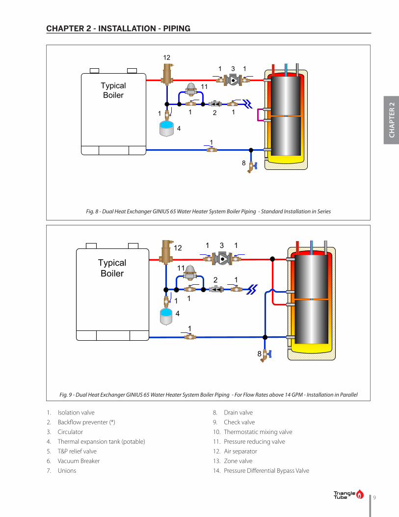
The dual heat-exchangers can be interconnected in series for general applications, or in parallel for higher flow rates, above 14 GPM.In applications with two energy sources, both heat-ex-changers can be connected individually with one or both heat sources. In that case, it is advised to connect the source providing the highest temperature profile to the upper heat-exchanger.
ix
INTRODUCTION - PRODUCT DESCRIPTION
INTR
OD
UC
TIO
N
Fig. 1 - GINIUS Series Description
1. Domestic hot water outlet (red color)
2. Cold water inlet (blue color), with dip tube
3. Auxiliary connection (black color)
4. Temperature control panel
5. Stainless steel domestic tank
6. Boiler water (primary) supply
7. Boiler water (primary) return
8. Stainless steel heat-exchanger
9. Drain
10. Dry well
GINIUS 35 - 45 - 55 GINIUS 65
8
8
8
10
10
1
5
6
6
6
7
7
7
5
23
4
32
1
1
1
6
7
423
7
7
6
6
32
99

INTENTIONALLY LEFT BLANK

1
CHA
PTER
1
CHAPTER 1 - PRE-INSTALLATION
1.1. Codes Compliance
Water heater installation must conform with the in-structions in this manual and where applicable:
• local, state, provincial, and national codes, laws, regulations and ordinances.
• in Canada - CAN / CGA B149.1 or B149.2 Instal-lation Code.
GINIUS water heaters are exempt from ASME Section VIII, Division 1 Code construction per Interpretation VIII-86-136. Check with local codes for applicability.
GINIUS Series water heaters will absorb less than 200,000 BTU/hr when domestic wa-ter outlet temperature is 210ºF and boil-er water supply temperature is 240ºF. List-ed outputs are based on ASME Section VIII
Interpretation VIII-1-86-136.
Where recommendations in this manual differ from lo-cal, or national codes, the local or national codes take precedence.
1.2. Codes Restrictions
Single wall heat exchanger in the GINIUS water heater complies with National Standard Plumbing Code, pro-vided that:
• Boiler water (including additives) is practically non-toxic, having toxicity rating or class of 1, as listed in Clinical Toxicology of Commercial Prod-ucts, and
• Boiler water pressure is limited to maximum 30 psig by approved relief valve.
Single wall heat exchangers are permitted under the Uniform Plumbing code - Paragraph L3.2. and L3.3 if they satisfy all of the following requirements.1. The heat transfer medium is potable water or con-
tains only substances which are recognized as safe by the U.S. Food and Drug Administration.
2. The pressure of the heat transfer medium is main-tained less than the normal minimum operating pressure of the potable water system
Exception: Steam complying with section #1 above.
3. The equipment is permanently labeled to indicate that only additives recognized as safe by the FDA shall be used in the heat transfer medium.
NOTICE
Other heat exchanger designs may be permitted where approved by the Administrative Authority.
1.3. Operating Restrictions
• Maximum domestic hot water temperature is 194ºF for commercial applications and 140ºF for residen-tial applications.
• Maximum boiler water temperature is 210ºF.• Maximum working pressure for (domestic water)
tank is 150 psig.• Maximum working pressure for the heat exchanger
(boiler water) tank is 80 psig.• Water quality limitations (based on E.P.A National
Secondary Drinking Water Regulations): – Chloride, less than 150 ppm or mg/l – pH value min. 6, max. 8 – Total hardness 3 - 7 grains/gallon or 50-120
ppm or mg/l. – Total Dissolved Solids (TDS), less than 120 ppm
or mg/l. – Iron less than 0.3 ppm or mg/l. – Aluminum, less than 0.2 ppm or mg/l. – Copper, less than 1 ppm or mg/l. – Manganese, less than 0.05 ppm or mg/l. – Zinc, less than 5 ppm or mg/l.
In hard water areas (more than 7 grains of hardness) soften the cold domestic supply wa-
ter to the appliance to prevent scaling.
BEST PRACTICE
• Any water conditioning system must be in-stalled and maintained in accordance with
manufacturer’s specifications.
• Do not install the water heater on any appli-cation if the boiler piping contains non-ox-ygen barrier tubing or if the boiler piping is considered an “open system”. Exposing the tank of the water heater to oxygen contam-ination will lead to premature tank failure
and denial of the warranty.
NOTICE

2
CHA
PTER 1
CHAPTER 1 - PRE-INSTALLATION
1.4. Locating Water Heater
• This water heater is not intended for outdoor instal-lations.
• Keep distance between boiler and water heater to a minimum to:
– Reduce piping heat loss – Provide minimal friction loss
• Locate water heater so that any leakage from the tank or water connections will not cause damage to the area adjoining the water heater or to lower floors in the structure.
– When such a location is unavoidable, a suitable drain pan with adequate drainage, should be placed under the water heater.
• The GINIUS Series Water Heaters are designed for vertical installation only.
BEST PRACTICE
1.5. Recommended Clearances
Water heater should be installed to allow adequate clearance for servicing.Zero clearance is permissible to any side of the GINIUS Series water heater that has no connection, but infor-mation labels may be hidden. Also take into account the clearance required for any accessory that needs to be installed on the heating and/or domestic circuits.
• Recommended top or vertical clearance is 12” minimum.
• Refer to boiler manual for boiler clearances.
Fig. 2 - GINIUS - Clearances

3
CHA
PTER
2
CHAPTER 2 - INSTALLATION - PIPING
2.1. Temperature & Pressure (T&P) Relief Valve
To reduce risk of excessive pressures and temperatures in the water heater, install tem-perature and pressure protective equipment required by local codes, but no less than a com-bination temperature and pressure relief valve certified by a nationally recognized testing lab-oratory that maintains periodic inspection of production of listed equipment or materials, as meeting the requirements for Relief Valves and Automatic Gas Shutoff Devices for Hot Water Supply Systems, ANSI Z21.22. This valve must be marked with a maximum working pressure
of the water heater.
• Every GINIUS water heater must be protected with a T&P relief valve.
• Determine T&P relief valve size by the following specifications, unless they conflict with local codes:
– GINIUS 35/45/55: 3/4”NPT with an AGA Rating of 100,000 BTU/hr and a maximum pressure rat-ing of 150 psig. (Watts 100XL or equivalent).
– GINIUS 65: 3/4”NPT with an AGA Rating of 200,000 BTU/hr and a maximum pressure rating of 150 psig. (Watts 40XL or equivalent).
CAUTION
2.2. Standard Installation
• Install T&P relief valve in the Auxiliary connection located on the right side of the water heater top cap (Refer to Fig 3 below and Fig. 5 on page 7).
2.3. T&P Relief Valve Discharge Piping
• T&P relief valve discharge piping must be: – Made of material serviceable for temperatures
of 250ºF or greater. – Directed so that hot water flows away from all
persons. – Directed to a suitable place for disposal. – Installed so as to allow complete draining of the
T&P relief valve and discharge line.• T&P relief valve discharge piping must not be:
– Excessively long. Using more than 2 elbows or 15 feet of piping can reduce discharge capacity.
– Directly connected to a drain. Terminate dis-charge piping within 6” from drain. Refer to local codes.
– Plugged, reduced or restricted. – Subject to freezing.
Do not install any valve between T&P relief valve and tank connection or on T&P relief valve discharge piping. Do not plug T&P relief valve or discharge piping. Improper placement and piping of T&P relief valve can cause substantial property damage, serious
injury, or death.
WARNING
Fig. 3 - GINIUS Domestic Connection Arrangement
Auxiliary Connection
Domestic Hot Water outlet connection
Cold Water inlet con-nection & dip tube

4
CHA
PTER 2
CHAPTER 2 - INSTALLATION - PIPING
2.4. Drain Valve
Drain valve and fittings are supplied by others.Standard Installation• Install a drain valve at the domestic water drain
connection (Refer to Fig. 1 on page ix).• Pipe the drain piping with drain valve from the
drain connection to: – a suitable place for disposal
or – terminate within 12” of the floor
2.5. Thermal Expansion
If a backflow preventer, check valve or pressure reduc-ing valve is piped on cold water supply piping of water heater, install an expansion tank on cold water supply line to prevent normal thermal expansion from repeat-edly forcing open T&P relief valve.
T&P relief valve is not intended for constant duty, such as relief of pressure due to repeated normal system expansion. Correct this condi-tion by installing a properly sized expansion
tank in domestic water system.
Refer to expansion tank manufacturer’s instal-lation instructions for proper sizing.
2.6. Water Hammer
Dishwashers, clothes washers and fast-closing positive shut-off valves incorporated in the system all contrib-ute to creating water shock. Install a water hammer ar-rester to prevent damage to pipes and appliances. See device manufacturer’s instructions for application and installation.
Water hammering within the domestic piping system can cause premature failure of the tank of the water heater. This type of failure is NOT
covered under warranty.
CAUTION
NOTICE
2.7. Vacuum Breaker
Installing a vacuum breaker (Watts N36-M1 or equiva-lent) on the domestic cold water inlet will prevent dam-age to the tank if a negative pressure is developed in the domestic supply line. See manufacturer’s instructions for application and installation of the vacuum breaker.
2.8. General Piping
• For domestic water piping diagram, see Fig. 5 on page 7.
• For Boiler water piping, see Fig. 6 on page 8 thru Fig. 10 on page 10.
• See Table 1 on page 5 for domestic and boiler piping connection sizes .
• All plumbing must meet or exceed all local, state and national plumbing codes.
• Use pipe dope or tape suitable for potable water systems
• Use isolation valves to isolate system components.
2.9. Domestic Piping• Union on the domestic hot water outlet should be
piped at a higher elevation than domestic water drain valve. This will make draining the water heater easier.
• Install unions for easy removal of water heater. It is recommended to use dielectric unions or cou-plings to protect hot and cold water fittings from corrosion when connecting dissimilar materials such as copper and galvanized iron pipe.
• If copper pipe is used for domestic water connections, first solder pipe to a threaded adapter and then screw adapter into cold water inlet on top of water heater. Inlet connection contains an internal plastic dip tube which can be damaged by heat from soldering.
Do not apply heat to the cold water inlet when making sweat connections to water heater. Sweat tubing to adapter before fitting adapter to cold water inlet of heater. It is imperative that no heat be applied to the cold water inlet, as it
contains a non metallic dip tube.
NOTICE

5
CHA
PTER
2
CHAPTER 2 - INSTALLATION - PIPING
• When the water supply pressure is higher than 70 psig, it is recommended to install a pressure reduc-ing valve on cold water supply line to prevent wa-ter loss through T&P relief valve.
• If the water heater will replace a tankless coil in the boiler, disconnect the piping to coil and allow the water to drain from coil. Do not plug the tankless coil.
Plugging tankless coil inlet and outlet will re-sult in substantial property damage, serious
injury, or death.
2.10. Thermostatic Mixing Valve
• It is recommended to install an optional mixing valve on the domestic hot water outlet.
• Mixing valve must comply with ASSE 1017 Recircu-lation Piping
• A stainless steel or bronze circulator is required on potable water systems.
• Install an automatic mixing valve either at the hot wa-ter outlet of water heater or each hot water faucet.
DANGER
Table 1 - Piping dimensions
Water Heater Model
ConnectionsRecirculation Dip
TubeDip Tube
Recommend-ed Minimum Boiler Piping
Domestic Water
Inlet/Outlet (NPT)
Boiler Water Supply/ Return (NPSC)
Auxiliary Connec-
tion (NPT)
Domestic Drain Con-
nection (NPSC)
Length (Inches)
Diam-eter
(Inches)
Length (Inches)
Diameter (Inches)
Diameter (Inches)
GINIUS 35 3/4 1 3/4 3/4 25 3/4 43 3/4 1GINIUS 45 3/4 1 3/4 3/4 25 3/4 52 3/4 1GINIUS 55 3/4 1 3/4 3/4 34 3/4 62 3/4 1GINIUS 65 3/4 1 3/4 3/4 34 3/4 71 3/4 1
2.11. Multiple Water Heater Systems
• For multiple water heater domestic and boiler pip-ing, see Fig. 11 on page 10 and Fig. 12 on page 11.
• Install an automatic mixing valve either at the hot wa-ter outlet of water heater or each hot water faucet.
Failure to install automatic mixing valve where recommended will result in serious in-
jury, or death.
DANGER
2.12. Boiler Piping
• If plastic pipe is used for boiler water piping, it must have a maximum oxygen diffusion rate of 0.1 mg/liter-day for boiler and water heater protection.
The GINIUS IDWH must be installed on a closed type hydronic system. Failure to provide such a system will result in premature failure of the
tank and annulment of warranty.
• Boiler water (including additives) must be practical-ly non-toxic, having toxicity rating or class of 1, as listed in Clinical Toxicology of Commercial Products.
Antifreeze can only be used if the boiler water pressure relief valve is set to 30 psig or below.
If antifreeze is used in the boiler system, local codes may require a backflow preventer on cold water supply line. Use antifreeze specifically intended for hydronic heating systems. Inhibited propylene gly-col is recommended at a maximum 50/50 mixture.
Do not use automotive, ethylene glycol or petroleum-based antifreeze. Do not use any undiluted antifreeze. This can cause substan-tial property damage, serious injury, or death.
NOTICE
CAUTION
DANGER

6
CHA
PTER 2
CHAPTER 2 - INSTALLATION - PIPING
Fig. 4 - Piping Components Legends

7
CHA
PTER
2
CHAPTER 2 - INSTALLATION - PIPING
Fig. 5 - Standard Installation Domestic Piping with optional Recirculation - GINIUS Series
1. Isolation valve
2. Backflow preventer or Pressure reducing valve (*)
3. Circulator
4. Thermal expansion tank (potable)
5. T&P relief valve
6. Vacuum Breaker
7. Unions
8. Drain valve
9. Check valve
10. Thermostatic mixing valve
(*) Optional devices may be required by local codes
DHW Outlet
Cold Water Inlet
12" min. Heat Trap Loop (optional)
12
4
15
10
7 7
12" min. Heat Trap Loop (optional)
1
Optional Recirculation
Loop 1 13 9
6
8

8
CHA
PTER 2
CHAPTER 2 - INSTALLATION - PIPING
Fig. 6 - GINIUS System Piping with Zone Valves (Domestic Priority)
Fig. 7 - GINIUS System Piping with Zone Circulators
1. Isolation valve
2. Backflow preventer (*)
3. Circulator
4. Thermal expansion tank (potable)
5. T&P relief valve
6. Vacuum Breaker
7. Unions
8. Drain valve
9. Check valve
10. Thermostatic mixing valve
11. Pressure reducing valve
12. Air separator
13. Zone valve
14. Pressure Differential Bypass Valve
TypicalBoiler
2
12
1 11
11
1
3
4
911
8 88
7
7
11
Z.V.
Z.V.
1 131313
9
14
Typical Boiler
2
12
1 11
11
1
31
1
3
1
1
3
4
9
99
11
8 8 8
7
7
11
9
CHA
PTER
2
CHAPTER 2 - INSTALLATION - PIPING
1. Isolation valve
2. Backflow preventer (*)
3. Circulator
4. Thermal expansion tank (potable)
5. T&P relief valve
6. Vacuum Breaker
7. Unions
8. Drain valve
9. Check valve
10. Thermostatic mixing valve
11. Pressure reducing valve
12. Air separator
13. Zone valve
14. Pressure Differential Bypass Valve
Fig. 8 - Dual Heat Exchanger GINIUS 65 Water Heater System Boiler Piping - Standard Installation in Series
Fig. 9 - Dual Heat Exchanger GINIUS 65 Water Heater System Boiler Piping - For Flow Rates above 14 GPM - Installation in Parallel
1231 1
8
TypicalBoiler
1
2 11 1
4
11
1
1 1312
2
4
8
1
TypicalBoiler
1
1
11

10
CHA
PTER 2
CHAPTER 2 - INSTALLATION - PIPING
Fig. 10 - GINIUS Series Water Heater System boiler Piping - Multi Power Sources
1
1 1312
2
4
8
1
Secondary Heat Source
1
1
11 3 12
2
4
8
1
TypicalBoiler
1
1
11
1
11
Fig. 11 - Multiple GINIUS Series Water Heater System Boiler Piping - Reverse Return Balanced Flow
1
1 13
12
112
4
8
TypicalBoiler
11
1. Isolation valve
2. Backflow preventer (*)
3. Circulator
4. Thermal expansion tank (potable)
5. T&P relief valve
6. Vacuum Breaker
7. Unions
8. Drain valve
9. Check valve
10. Thermostatic mixing valve
11. Pressure reducing valve
12. Air separator
13. Zone valve
14. Pressure Differential Bypass Valve

11
CHA
PTER
2
CHAPTER 2 - INSTALLATION - PIPING
12
41
DHW Outlet
1 13 9
Optional Recirculation
Loop
10
6
577 577 577Cold
Water Inlet
8 8 8
1. Isolation valve
2. Backflow preventer or Pressure reducing valve (*)
3. Circulator
4. Thermal expansion tank (potable)
5. T&P relief valve
6. Vacuum Breaker
7. Unions
8. Drain valve
9. Check valve
10. Thermostatic mixing valve
(*) Optional devices may be required by local codes
Fig. 12 - Multiple GINIUS Series Water Heater System Domestic Piping - Parallel

INTENTIONALLY LEFT BLANK

13
CHA
PTER
3
CHAPTER 3 - INSTALLATION - WIRING
3.1. Wiring Requirements
Electrical shock hazard can cause substantial property damage, serious injury, or death. Disconnect power before installing and/or
servicing.1. All wiring must be a minimum of 18 gauge and in-
stalled in accordance with:• U.S.A. - National Electrical Code and any other
national, state or local code requirements hav-ing jurisdiction.
• Canada - C.S.A. C22.1 Canadian Electrical Code Part 1 and any other national, provincial and lo-cal code requirements having jurisdiction.
2. If original wire supplied with appliance must be re-placed, Type 90ºC or its equivalent must be used.
3. Refer to control component instructions packed with boiler for application information.
4. An optional service switch may be installed in water heater electrical circuit. This switch would only shut off the water heater, not the home heating system. Do not shut off water heater if there is a chance of freezing.
5. All electrical contacts shown do not have power ap-plied - off the shelf condition. See pages 14 thru 17.
3.2. Circulators
Priority relay must be sized for total amp draw of all cir-culators.
WARNING
3.3. Zone Valves
Transformer must be sized for maximum load of all zone valves.
3.4. Snap Set Connection
For easy wiring between water heater thermostat and boiler controls see wiring diagrams in following pages (refer to Fig. 14 on page 14 thru Fig. 20 on page 17).Make sure snap set is firmly snapped together after wir-ing.
Fig. 13 - Snap Set Wiring

14
CHA
PTER 3
CHAPTER 3 - INSTALLATION - WIRING
Fig. 14 - Typical 4-wire Zone Valve Zoning, with Domestic Priority Fig. 15 - Typical 3-wire Zone Valve Zoning, with Domestic Priority
H N
High Voltage
120V.A.C.
24V.A.C.
RoomThermostat
Zone 1
Additional zones Additional zones maybe added as shown above
Transformer(Power)
Zone Valve
Zone Valve
12C
Water HeaterThermostat
Snap-SetWaterHeaterZone
BoilerThermostatTerminals
High VoltageLow VoltageBoiler Low Voltage
PriorityRelay
High Voltage
120V.A.C.
24V.A.C.
RoomThermostat
Zone 1
Additional zones Additional zones maybe added as shown above
Transformer(Power)
Zone Valve
Zone Valve
12C
Water HeaterThermostat
Snap-SetWaterHeaterZone
*Isolation Relay
BoilerThermostatTerminals
* Use isolation relay on3-wire zone valves withnon-isolated end switches.Transformer and boilercontrol can burn out if isolation relay is not used
PriorityRelay

15
CHA
PTER
3
CHAPTER 3 - INSTALLATION - WIRING
Fig. 16 - Typical 4-wire Zone Valve Zoning, without Domestic Priority
Fig. 17 - Typical 3-wire Zone Valve Zoning, without Domestic Priority
H N
High Voltage
120V.A.C.
24V.A.C.
RoomThermostat
RoomThermostat
Zone 1
Zone 2
Additional zones Additional zones maybe added as shown above
Transformer(Power)
Zone Valve
Zone Valve
Zone Valve
12C
Water HeaterThermostat
Snap-SetWaterHeaterZone
BoilerThermostatTerminals
High VoltageLow VoltageBoiler Low Voltage
H N
High Voltage
120V.A.C.
24V.A.C.
RoomThermostat
RoomThermostat
Zone 1
Zone 2
Additional zones Additional zones maybe added as shown above
Transformer(Power)
Zone Valve
Zone Valve
Zone Valve
12C
Water HeaterThermostat
Snap-SetWaterHeaterZone
*Isolation Relay
BoilerThermostatTerminals
* Use isolation relay on3-wire zone valves withnon-isolated end switches.Transformer and boilercontrol can burn out if isolation relay is not used

16
CHA
PTER 3
CHAPTER 3 - INSTALLATION - WIRING
Fig. 18 - Typical Circulator Zoning with Domestic Priority Fig. 19 - Typical Circulator Zoning without Domestic Priority
2
T T
1 4 3 5 6
CirculatorZone 1
Thermostatzone 1Honeywell
R845ARelay
120H
VACN
2
T T
1 4 3 6
CirculatorZone 2
Thermostatzone 2
5
2
T T
1 4 3 6
WaterHeater
Circulator
Water HeaterThermostat
Snap-Set
5
12
C
BoilerThermostatTerminals
Priority Relay
2
T T
1 4 3 5 6
CirculatorZone 1
Thermostatzone 1Honeywell
R845ARelay
120H
VACN
2
T T
1 4 3 6
CirculatorZone 2
Thermostatzone 2
5
2
T T
1 4 3 6
WaterHeater
Circulator
Water HeaterThermostat
Snap-Set
5
12
C
High VoltageLow Voltage
BoilerThermostatTerminals

17
CHA
PTER
3
CHAPTER 3 - INSTALLATION - WIRING
Fig. 20 - Priority Zone Circulator Wiring
T T
1 4 3 5 6
CirculatorZone 1
Thermostatzone 1Honeywell
R845ACirculator
Relay
120H
VACN
2
T T
1 4 3 6
CirculatorZone 2
CirculatorZone 3
Thermostatzone 2
Thermostatzone 3
5
2
T T
1 4 3 65
High VoltageLow Voltage
To Boiler 24 VACThermostat Leads
2
ON PRIORITY
ZON
ING
CIRCULATO
R
CIRCON
PR1 LIVENEUT
T T
2
1C
Water HeaterThermostat Snap Set
Priority ZoneCirculator
Note: Maximum of 4 total circulator zone when wiring
1 zone for priority

INTENTIONALLY LEFT BLANK

19
CHA
PTER
4
CHAPTER 4 - WATER HEATER START-UP
4.1. Filling the primary (Boiler Water) circuit
• Never use the water heater unless primary (Boiler water) circuit and (Domestic water)
tank are completely filled with water.
• Primary circuit must be completely filled and pressurized before pressurizing tank.
1. Close boiler water drain valve at boiler water outlet of water heater.
2. Open water heater’s boiler water isolation valves.3. Follow instructions furnished with boiler to fill with
water and vent the primary (boiler water) circuit.
Antifreeze can only be used if the boiler water pressure relief valve is set to 30 psig or below.
4. If antifreeze is used in boiler water, check concen-tration. Boiler water (including additives) must be practically non-toxic, having toxicity rating or class of 1, as listed in Clinical Toxicology of Commercial Products.
Do not use automotive, ethylene glycol or pe-troleum-based antifreeze. Do not use any un-diluted antifreeze. This can cause substantial
property damage, serious injury, or death.
4.2. Filling the (Domestic Water) Tank
• Never use the water heater unless primary (Boiler water) circuit and (Domestic water)
tank are completely filled with water.
• Primary circuit must be completely filled and pressurized before pressurizing tank.
1. Close domestic water drain valve.2. Open domestic water isolation valves for water
heater.3. Vent air from (domestic water) tank by opening
nearest hot water faucet. Fill domestic water tank completely by allowing water to run until there is a constant flow of water.
4. Close hot water faucet.
CAUTION
CAUTION
WARNING
CAUTION
HOT WATER CAN SCALD!Water temperature over 125ºF can cause se-
vere burns instantly or death from scalds.
• Feel water before bathing or showering.• Consumer Product Safety Commission
and some states recommend tempera-tures settings of 130ºF or less. Setting ther-mostat higher than 130ºF will increase risk of scald injury and cause severe personal injury or death.
• Water heated to a temperature suitable for clothes washing, dish washing and other sanitizing needs will scald and cause permanent injury.
• Children and elderly, infirm, or physically handicapped persons are more likely to be injured by hot water. Never leave them unattended in or near a bathtub. If anyone using hot water in the building fits this description, or if state laws or local codes require certain water temperatures at hot water faucets, take special precautions.
– Install an automatic mixing valve at water heater or at each hot water fau-cet, bath and shower outlet. Selection and installation must comply with valve manufacturer’s recommenda-tion and instructions.
– Use the lowest practical temperature setting.
– Check water temperature after any ad-justment. You must follow “Adjusting the Water Heater Thermostat” procedures.
At no time should boiler limit control be set above 210ºF. This can cause substantial prop-erty damage, serious injury, or death if ig-
nored.
DANGER
WARNING

20
CHA
PTER 4
CHAPTER 4 - WATER HEATER START-UP
• Household water usage patterns will af-fect water temperature at any faucet or shower. Occasionally check temperature at each point of use, then adjust thermostat accordingly. Always recheck temperature
after adjusting thermostat.
• When hot water is used in repeated small quantities, a “stacking” effect can develop in the water heater. The upper layer of wa-ter in tank can be hotter than lower layer, resulting in very hot water coming out at
the faucet.
• It is therefore recommended to either lower the thermostat setting or install automatic mixing valves as indicated in these instruc-tions in order to reduce water temperature levels. Consult your installer or service tech-
nician.
NOTICE
CAUTION
4.3. Adjusting the Water Heater Thermostat
Water heater thermostat is factory set to its lowest temperature. This may or may not be suitable for your needs.• Turn thermostat knob clockwise to in-
crease water temperature.• Turn thermostat knob counter-clockwise
to decrease water temperature.
Bacteria can develop in the domestic water system if certain minimum water tempera-tures are not maintained. Failure to maintain at least 140°F [60°C] domestic hot water tem-perature (using the Antilegionella function of your boiler, if any) can result in bacteria development, which can result in serious in-
jury, or death.
• Check water temperature at a hot water faucet im-mediately after first heating cycle. Further tempera-ture adjustment may be necessary as water heating system is used. Recheck water temperature at fau-cet after adjustment.
• When adjusting thermostat, be sure boiler limit control is set a minimum of 20ºF higher.
WARNING
Temperature Up
Temperature Down
Fig. 21 - GINIUS Series Temperature Knob

21
CHA
PTER
5
CHAPTER 5 - WATER HEATER MAINTENANCE
5.1. Maintenance Schedule
5.1.1 Annual service by qualified service tech-nician should include the following:
¨ Any procedure required by local codes. ¨ Verify system pressure. Air venting procedure may
require adding water to bring system up to pres-sure, typically 12 psig.
¨ Manually operate T&P relief valve at least once a year. This will release some hot water.
Before operating T&P relief valve, make sure no one is in front of or around T&P relief valve discharge piping. Hot discharge water can cause substantial property damage or seri-
ous injury.
¨ Move operating lever to open position for a few seconds and then move it back, allowing it to snap closed. After T&P relief valve is operated, if it contin-ues to release water, close cold water inlet to water heater immediately. Follow draining instructions, to relieve pressure from the tank and replace T&P relief valve. If T&P relief valve weeps periodically, it may be due to thermal expansion see Section 2.5 on page 4. Do not plug T&P relief valve or dis-charge piping.
Plugging T&P relief valve or discharge piping can cause excessive pressure in water heater, resulting in substantial property damage, se-
rious injury, or death.
¨ Follow instructions on circulator to oil it, if required. ¨ Check mixing valve, valves, pipes and fittings for
leaks. ¨ Check function of field-installed controls and valves.
See component manufacturer’s instructions. ¨ Review homeowner’s maintenance responsibilities
and their frequencies, including any not listed in the following section.
WARNING
WARNING
5.1.2 Homeowner monthly maintenance to in-clude:
¨ Check for leaks.• Visually check valves, pipes and fittings for leaks.
Call qualified service technician to repair any leaks.
5.2. Filling Water Heater
See Sections 4.1 and 4.2 on page 19.
5.3. Draining Water Heater
Drain water heater if it will be shut off and exposed to freezing temperatures. Freezing water will expand and damage water heater.
• If boiler water contains sufficient antifreeze, then only the domestic water needs to be drained.
• If boiler water does not contain sufficient antifreeze, then the boiler water and domestic water must be drained.
Close domestic water isolation valves and drain the tank before draining primary circuit
to prevent damage to primary circuit.
If antifreeze is used in boiler water, check concentration.Boiler water (including additives) must be practically non-toxic, having toxicity rating or class of 1, as listed in Clinical Toxicology of Commercial Products. A max-imum 50/50 mixture of inhibited propylene glycol is recommended. Follow antifreeze manufacturer’s in-struction.
Do not use automotive, ethylene glycol or pe-troleum-based antifreeze. Do not use any un-diluted antifreeze. This can cause substantial
property damage, serious injury, or death.
CAUTION
WARNING

22
CHA
PTER 5
CHAPTER 5 - WATER HEATER MAINTENANCE
Water from opened drain valves, unions and other connections may be extremely hot. To avoid substantial property damage, serious
injury, or death:
- Tighten all drain hose connections.
- Direct hot water away from all persons.
5.3.1 Draining (Domestic Water) Tank.
Prior to draining the tank, ensure the following is completed:
• The snap-set wiring connection at the wa-ter heater is disconnected.
• The DHW system supply isolation valve is closed.
Reference domestic piping diagram, see Fig. 5 on page 7.
1. Close the domestic water isolation valves.2. Open the domestic water drain valve to start emp-
tying the domestic tank.3. Open a hot water faucet at the highest point above
the water heater to increase draining speed.4. When draining is complete, close the hot water fau-
cet and the domestic drain valve.
WARNING
NOTICE
5.3.2 Draining Primary (Boiler Water) circuit
Close domestic water isolation valves and drain the domestic tank before draining pri-mary circuit to prevent damage to primary
circuit.1. Disconnect snap set wiring connection at water
heater.2. Close boiler water isolation valves between boiler
and water heater.3. Connect hose to boiler water drain valve at water
heater. Open and drain water to a safe place.4. To speed up the draining procedure, open manual
air vent on the boiler, if any.5. When draining is complete, close drain valve and
close manual air vent (on the boiler, if any).
CAUTION

23
CHA
PTER
6
CHAPTER 6 - REPLACEMENT PARTS
Item Part # Model Description
1 P3KITTH01 All Aquastat 160°F - residential
2 P3KITBTM02 All Bottom cap
3 P3KITTOP02 All Top cap
4
P3DW01 GINIUS 35
Dry wellP3DW02 GINIUS 45P3DW03 GINIUS 55P3DW07 GINIUS 65
5
P3WKITDT02 GINIUS 35
Dip TubeP3WKITDT03 GINIUS 45P3WKITDT04 GINIUS 55P3WKITDT06 GINIUS 65
6P3WKITDT01 GINIUS 35-45
Dip tube, recirculation (optional)P3WKITDT02 GINIUS 55-65
7 P3KITWRS01 All Snap-set wire harness
8 P3KNB02 All Knob
9 P3CVR04 All Cover plate
39
4
2
5
Fig. 22 - GINIUS Assembly
9
7
8
1
Fig. 23 - GINIUS Cover Plate Assembly

24
CHA
PTER 7
CHAPTER 7 - WATER HEATER SPECIFICATIONS AND PERFORMANCES
Hot Water Outlet
Cold Water Inlet
Auxiliary Connection
A
B
C
D
Boiler Return
Boiler Return
Boiler Return
Boiler Supply
Boiler Supply
Boiler Supply
Cold Water Inlet
Auxiliary Connection
A
B
C
D
Fig. 24 - GINIUS 35-45-55 Dimensions
Fig. 25 - GINIUS 65 Dimensions
Hot Water Outlet
(*)
(*)
Drain connection (height = B)
Drain connection (height = B)

25
CHA
PTER
7
CHAPTER 7 - WATER HEATER SPECIFICATIONS AND PERFORMANCES
Model GINIUS 35 GINIUS 45 GINIUS 55 GINIUS 65Capacity Gal. 35 45 55 65
Domestic Gal 34 44 54 64Boiler Gal 1 1 1 2
Heating Surface Sq. Ft. 12 1/2 12 1/2 12 1/2 2 x12 1/2Head Loss Boiler Side Ft. 7 7 7 2 x 7Piping Connections Inches
Domestic Ø 3/4 3/4 3/4 3/4Boiler Ø 1 1 1 1Auxiliary Ø 3/4 3/4 3/4 3/4Drain Ø 3/4 3/4 3/4 3/4
DimensionsA Inches 44 54 64 72B Inches 10 1/2 10 1/2 10 1/2 10 1/2/36(*)C Inches 29 29 29 29/55(*)D Inches 22 22 22 22E Inches 7 7 7 7
Dry well length Inches 29 37 47 51Empty weight Lbs. 96 110 124 164
Fig. 26 - GINIUS 35-45-55-65 Dimensions
Table 2 - Ginius Water Heater Specifications
Hot Water Outlet
Cold Water Inlet
Thermostat & Cover Plate
Auxiliary Connection
E E

26
CHA
PTER 7
CHAPTER 7 - WATER HEATER SPECIFICATIONS AND PERFORMANCES
ModelBoiler Heating
Capacity (BTU/Hr)
Peak Flow Gal./10 min.
1st Hour Flow Gal./Hour
Continuous Flow
Gal./Hour
Circulator Min. GPM
GINIUS 35 92,000 45 145 120 14GINIUS 45 92,000 55 155 120 14GINIUS 55 92,000 63 163 120 14GINIUS 65 Single 92,000 70 170 120 14GINIUS 65 Series 170,000 88 275 225 14GINIUS 65 Parallel 182,000 90 290 240 26.5
Conditions: • 50ºF Domestic cold water inlet temperature• 140ºF Domestic hot water outlet temperature• 180ºF Boiler water supply temperature• Calculations based on BTU/Hr and 80% of tank storage as “useable”
ModelBoiler Heating
Capacity (BTU/Hr)
Peak Flow Gal./10 min.
1st Hour Flow Gal./Hour
Continuous Flow
Gal./Hour
Circulator Min. GPM
GINIUS 35 155,000 60 230 205 14GINIUS 45 155,000 70 240 205 14GINIUS 55 155,000 80 250 205 14GINIUS 65 Single 155,000 85 255 205 14GINIUS 65 Series 270,000 110 415 365 14GINIUS 65 Parallel 280,000 115 430 380 26.5
Conditions: • 50ºF Domestic cold water inlet temperature• 140ºF Domestic hot water outlet temperature• 200ºF Boiler water supply temperature
Table 3 - Ginius Water Heater Performance at 180°F Boiler Water Supply
Table 4 - Ginius Water Heater Performance at 200°F Boiler Water Supply


28
Additional quality water heating equipment available from Triangle Tube
Triangle Tube - 1240 Forest Parkway, Suite 100, West Deptford NJ 08066
Tel: (856) 228 8881 - Fax: (856) 228 3584 - E-mail: [email protected]
• For domestic water, snow melting, radiant floor• Plates made of stainless steel, with 99.9 % copper
brazing, ensuring a high resistance to corrosion• Self cleaning and self descaling• Computerized sizing available from Triangle Tube• Available in capacities from 25,000 BTU/hr to
5,000,000 BTU/hr
• 95% AFUE• High Efficiency Condensing Boiler & Combi• Power Range 110 MBH, 155 MBH, 199 MBH• Turn Down Ratio up to 9.1:1• Natural Gas or Propane• Remote Internet Monitoring• Universal Top Adapter (PVC/PP/SST)• Outdoor Reset
TTP Brazed Plate Heat Exchangers
ION-IC Condensing Wall Mounted Boiler
Maxi-Flo Pool and Spa Heat Exchangers
• Constructed of high quality corrosion resistant stainless steel (AISI 316) or titanium
• Specially designed built-in flow restrictor to assure maximum heat exchange
• Compact and light weight• Available in 8 sizes to accommodate any size pool
or spa