Embed Size (px)
Citation preview

1
TECHNICAL SPECIFICATIONS FOR CIVIL, STRUCTURAL WORKS
SECTION - A
MATERIALS
1. Materials shall be of approved quality. A list of materials of approved brand and manufacturer is indicated in the ‘List of materials of Approved Brand and/or
Manufacture. The list is given to ensure the standard of quality and performance. 2. Contractors shall obtain approval of representative of Employer/Consultant on sample of
all materials before placing order and the approved sample shall be carefully preserved in an appropriate manner at the site office for verification by the representative of Employer/Consultant.
3. For standard bought out items, the sizes manufactured by the firms listed shal l prevail in
case of discrepancy with the sizes mentioned in the schedule without any financial
adjustment. 4. Materials shall be tested at site/any approved Testing Laboratory. The Laboratory Test
Certificate in original shall be submitted to the representative of Employer/Consultant.
Test results are also to be recorded at site registers appropriately. 5. Wherever work as per manufacturer’s specification is indicated, it will be obligatory on
the part of the contractor to submit manufacturer’s specification to Consultant/Employer. The quoted rates shall be deemed to include for the complete work specified by the manufacturer even though not specifically mentioned in the
schedule of items. Moreover, the quoted rates shall be deemed to include for the complete work specified
by the manufacturer even though not specifically mentioned in the schedule of items. 6. It shall be obligatory for the contractor to furnish certificates, if demanded by the
representative of Employer/Consultant, from manufacturer or the material supplier, stating that the work has been carried out by using their material.
7. All materials supplied by the representative or Employer/Consultant/any other special ist firm shall be properly stored and the Contractor shall be responsible for its safe custody until they are required on the works and till the completion of work.
8. All equipments and facilities for carrying out field tests on materials shall be provided by
the Contractor without any extra cost.
9. Unless otherwise shown on the Drawings or mentioned in the “Schedule of Quantities” or
anywhere in the contract, the quality of materials, workmanship, dimensions etc. shall be
as specified hereunder. 9.1 Material for fillings
Shall be selected materials as specified for filling and shall be free from building rubbish
or organic decomposed material. They shall be obtaining ei ther from excavation or
brought from outside, as specified, in the schedule of items.

2
9.2 Cement
Cement unless otherwise specified of grade 43, conforming to IS:455/IS:269 shall be used. The use of cement other than ordinary Portland cement/Blast furnace slag cem ent wil l not be allowed unless specifically advised by representative of Employer/Consultant.
Cement shall be stored in dry weatherproof godown/shed built by the Contractor at his
own cost in order to prevent deterioration by dampness or intrusion of foreign matter.
Not more than 10 bags should be kept in one stack and it shall be stored in such a manner as to permit easy access for proper inspection. It shall be stored in such a way as to allow the removal and use of cement in chronological order of receipt i .e. fi rst
received being first used. Cement deteriorated and/or clodded shall not be used on work but shall be removed at once from the site at Contractor’s cost.
Daily record of cement received and consumed shall be maintained by the Contractor in the cement register at site and submitted to representative of Employer/Consultant , i f called for. Theoretical consumption vis-à-vis materials brought at site by the Contractor
shall also be submitted with proper documents with every bill for verification. The consumption of cement for different items of work shall be as given in the tender and in its absence as per C.P.W.D. schedule. Consumption of cem ent in the corresponding
items of work under the contract shall be computed on the basis of the quantities shown in the able subject to a variation of plus/minus three percent. The w eight of 1 cum. of cement shall be taken as 1440 Kg.
9.3 Lime Lime shall be made from approved Lime Stone or Khankar and properly burnt and shal l
be of appropriate class for specific work given in IS: 712-1984. It shall be free from excess of unburnt khankar or lime stone ashes or other extraneous materials and shall be stored to prevent damage by rain, moisture or air slaking. Lime shall be used within 14 days from
the date of stacking and damaged lime shall not be used but shall be removed from the site of work forthwith at contractor’s cost.
9.4 Fine Aggregate Shall be from natural source, chemically inert, clean, sharp, hard, durable and well
graded and free from deleterious materials not exceeding the permissible limit as per IS : 383-1970. The Silt Content shall be within 8%. If it is in excess, washing shall be done in an approved manner to bring it within allowable limit.
The fine aggregate for concrete shall be graded and the Fineness Modules shall be
between 2.60 to 3.20.
The fine aggregate shall be stacked carefully on a clean bard dry surface so that it wil l
not get mixed up with deleterious foreign materials. If such a surface i s not available,
brick floor or a thin layer of lean concrete shall be prepared. The percentage of deleterious materials shall be within the permissible limits as specified in IS 383-1970.
9.5 Coarse Aggregate Shall consist of crushed or broken stone 95% of which shall be retained on 4.75 mm IS test
Sieve. It shall be obtained from crushing Granite, Trap, Basalt or similar approved stones. Coarse aggregate shall be chemically inert when mixed with cement and shall be roughly cubical in shape and free from soft friable, thin, laminated or flaky pieces. The
maximum percentage of deleterious materials shall not exceed those specified in IS:383:1970. The coarse aggregate used in the work shall conform to the grading as per limits specified in IS: 383-1970.
3
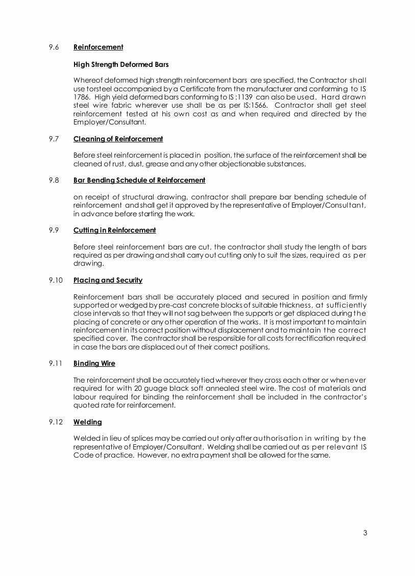
9.6 Reinforcement
High Strength Deformed Bars Whereof deformed high strength reinforcement bars are specified, the Contractor shal l
use torsteel accompanied by a Certificate from the manufacturer and conforming to IS 1786. High yield deformed bars conforming to IS :1139 can also be used. Hard drawn steel wire fabric wherever use shall be as per IS:1566. Contractor shall get steel
reinforcement tested at his own cost as and when required and directed by the Employer/Consultant.
9.7 Cleaning of Reinforcement
Before steel reinforcement is placed in position, the surface of the reinforcement shall be
cleaned of rust, dust, grease and any other objectionable substances. 9.8 Bar Bending Schedule of Reinforcement
on receipt of structural drawing, contractor shall prepare bar bending schedule of
reinforcement and shall get it approved by the representative of Employer/Consultant,
in advance before starting the work. 9.9 Cutting in Reinforcement
Before steel reinforcement bars are cut, the contractor shall study the length of bars
required as per drawing and shall carry out cutting only to suit the sizes, requi red as per drawing.
9.10 Placing and Security
Reinforcement bars shall be accurately placed and secured in position and firmly
supported or wedged by pre-cast concrete blocks of suitable thickness, at sufficiently close intervals so that they will not sag between the supports or get displaced during the
placing of concrete or any other operation of the works. It is most important to maintain reinforcement in its correct position without displacement and to maintain the correct specified cover. The contractor shall be responsible for all costs for rectification required
in case the bars are displaced out of their correct positions. 9.11 Binding Wire
The reinforcement shall be accurately tied wherever they cross each other or whenever
required for with 20 guage black soft annealed steel wire. The cost of materials and
labour required for binding the reinforcement shall be included in the contractor’s quoted rate for reinforcement.
9.12 Welding
Welded in lieu of splices may be carried out only after authorisation in wri ting by the
representative of Employer/Consultant. Welding shall be carried out as per relevant IS Code of practice. However, no extra payment shall be allowed for the same.

4
9.13 Bend, etc.
Bends, cranks etc. in steel reinforcement shall be carefully formed. Care being taken to
keep bends out of winding. Otherwise all rods shall be truly straight. For any bend minimum radius of eight times diameter of the bar shall be used unless otherwise
specified in the drawings. However, in respect of standard hooks the radius of bend shall be two times the diameter of bar. Heating of reinforcement bars to faci li tate bending will not be permitted. The bars shall always be bent cold. In case of mild steel
reinforcement bars of larger sizes where cold bending is not possible they m ay be bent by heating with written permission of the representative of Employer/Consultant . Bar when shall not be heated beyond cherry red colour and after bending, shall be allowed
to cool slowly without quenching. The bars damaged or weakened in any way in bending shall not be used on the work. high strength deformed bars shall in no case be heated to facilitate.
9.14 Inspection of Reinforcement
No concreting shall be commenced until the representat ive of Employer/Consultant
have inspected the reinforcement in position and until their approval have been obtained. A notice of at least 72 hours shall be given to the representative of
Employer/Consultant by the contractor for inspection of reinforcement, if in the opinion of the representative of Employer/Consultant any material is not in accordance with the specification or the reinforcement is incorrectly spaced. bent or otherwise defective, the contractor shall immediately remove such materials from the site and replace with new
and rectify any other defects in accordance with the instruction of the representative of Employer/Consultant to their entire satisfaction at his own cost.
9.15 Nett Measurement
Reinforcement shall be placed as shown in the structural drawings and payment wil l be
made on the nett measurement from drawings. Only such laps, dowels, in reinforcement shown on drawings shall be paid for. The Contractor shall allow in his quoted rates for all wastage and rolling margin which will be paid separately. The measured length of al l
the bars shall be converted into weight as per latest IS Schedule. 9.16 Stock Pilling Test
Steel required shall be stock piled well in advance of need in the work. Bar should be
stacked off the ground so that they do not get covered with mud.
9.17 Cover for Reinforcement
Cover shall be measured from the outer surface of main reinforcement. Cover shal l be
as follows :
a) At each end of a reinforcing bar, 25 mm or twice the diameter of such rod or bar, whichever is greater.
b) For longitudinal reinforcing in beams 25 mm or the diameter of such road or bar, whichever is greater.
c) For tensile, compressive, shear or in other reinforcement in slab 15mm or the diameter of such reinforcement whichever is greater.
d) For reinforcement in any other member such as a lintel, chajja, canopy or pardi , 15 mm or the diameter of such reinforcement, whichever is greater.

5
e) For main reinforcement in isolated footing (side and bottom) clear cover shall be 50 mm.
f) For column bars clear shall be 40 mm, unless otherwise specified in drawing.
g) For bars in slabs of strip footing and mat foundations clear cover shall be 50 mm. Slab bars shall be placed over beam bars in the case of beam and slab type foundations.
h) For any other types cover is specified in I.S. 456 shall be provided.
9.18 Rates quoted for reinforcement, in addition to any factors mentioned elsewhere, shal l also include for :
a) All cutting to length, labour in bending and cranking, forming hooked ends, handling, hoisting and everything necessary to fix reinforcement in work as per drawing.
b) Decoiling, straightening (coiled bars, bent bars to facilitate transporting)
c) Cost of binding wire require as described. d) Cost of precast concrete cover blocks of proper size or nylon spacers to maintain
cover and holding reinforcement in position.
e) For fabricating and fitting reinforcement in any structural member irrespect ive of
its location, dimensions and level.
f) Removal of rust and every other undesirable substances, using wire brush, etc. as
described.
g) Work at all levels.
h) Stock piling of reinforcement as described. 9.19 Bricks
The bricks shall be generally confirming to IS : 1077 first class kiln burnt bricks of regular
and uniform size, shape and colour, uniformly well burnt throughout but not over brunt.
they shall have rectangular faces with parallel sides and sharp, straight and right angled edges. They shall be free from cracks or other flaws. They shall have frog of 10 mm depth on one of their flat faces. Where first class bricks are not manufactured local ly or
nearby areas, best locally available bricks may be used having strength not less than that specified for the job by the Employer/Consultant.
They shall show a fine grained, uniform, homogenous and dense texture on fracture and be free from lumps of lime, laminations, cracks, air holes, soluble salts causing efflorescence or other defects which may in any impair their strength, durability,
appearance, usefulness for the purpose intended. After immersion in water, absorption by weight shall not exceed 20 percent of the dry
weight of the brick when tested according to IS 1077 - 1970. The bricks shall have a minimum average compressive strength as specified in the nomenclature of the i tems. The compressive strength of any individual bricks on testing shall not fall below the
average compressive strength by more than 20%. The rating of efflorescence of bricks shall not be more than ‘Moderate’.

6
The source, size and brand of the brick to be used for the entire work shall be approved by the Employer/Consultant beforehand from time to time.
9.20 Water
Water for mixing Cement/Lime mortar of concrete shall not be salty or Brackish and shall be clean, reasonably clear and free from injurious quantities of deleterious materials. It shall not contain any sugar or excess of oils, acid and injurious alkali, salts, organic matter
which will either weaken the mortar or concrete or cause efflorescence or attack the steel in reinforced cement concrete. Water shall be obtained from sources approved by the representative of Employer/Consultant, Potable water is generally considered
satisfactory for mixing an curing concrete, mortar, masonry etc. Water shall be tested once before undertaking the construction work in an approved test ing laboratory to establish its suitability. All charges connected therewith shall be borne by the Contractor.
The pH value of water shall generally be not less than 6. 9.21 Timber
Timber for carpentry/joinery works of all description shall be as specified in schedule and
seasoned, naturally or artificially as indicated therein. These shall be free from knot,
shakes, fissures, flaws, sub-cracks and other defects to a reasonable extent. Representative of Employer/Consultant’s decision in this regard is final and binding. The moisture content for timber normally should not exceed the following limits :
i) Timber for frames : 14% ii) Timber for planking/shutters etc. : 12%
Tolerance upto maximum 5% on above is permissible.
In measuring cross sectional dimensions of timber for the frames/shutters styles, rai ls or panel members, tolerance upto 1.5 mm shall be allowed for each planed surface.
9.22 Steel Windows & Doors Steel windows and doors shall be fabricated out of approved steel sections. They shal l
be obtained from approved manufacturers. 9.23 Vitrified & Ceramic Tiles
White or coloured vitrified tiles shall be obtaining from approved manufacturer and shall
be flat and true to shape. They shall be free from cracks, crazing, spots, chipped edges
and corners. The glazing and colour shall be of unform shade. Tolerance in dimension and colour + 1.0 mm in sizes and + 0.5 mm in thickness.
9.24 Kota/Cudappah Stone Slab shall be of selected quality, hard, sound, dense and homogeneous in texture, free
from cracks, decay, weathering and flaws. They shall be hand/machine cut to the specified thickness. The tolerance in thickness shall be + 2 mm.
9.25 Glazing Glass used for glazing shall be sheet glass/float glass as specified, clear or obscured as
directed by the Employer/Consultant of approved quality, free from flaws, specks, bubbles.

7
9.26 C.I. Rain Water Pipe
All C.I. pipes and fittings shall be of approved manufacturer free from cracks, chipped
edges or corners and other damages. The pipes shall be IS stamped.
9.15 Collapsible Gates
These shall be of approved manufacturer and fabricated from MS section consisting of
vertical double channels each 18 x 9 x 3 mm at 100 mm c/s braced with flat iron diagonal 18 x 5 mm and top and bottom rails of either I’s or E’s with minimum web of 40 x 12 mm and flange 40 x 6 mm. The roller wheels shall be of grey iron casting and rivets
shall be snap headed and not less than 6 mm dia. The gates shall be provided with necessary bolts and nuts, locking arrangements,
stoppers, handles etc. even if not specified. 9.16 Rolling Shutter
These shall be approved manufacturer and fabricated from MS laths o.9 mm thick upto 3
m opening and 1.2 mm thick for opening beyond 3 m and 80 mm wide in single pieces,
machine rolled and straightened with an effective bridge depth of 16 mm and shal l be interlocked together throughout their entire length and jointed at the end with end locks. These shall be mounted on specifically designed Pipe shaft. The springs shall be preferably coiled type manufactured from high tensile spring steel wire or strip of
adequate strength to balance shutter at all positions. The spring pipe shaft shall be supported on MS brackets and covered with MS sections as that of lath. The guide channels shall be of MS sections as that of lath. The guide channels shall be of MS deep
channel pressed/rolled sections with thickness not less than 3.15 mm and depth 60 m m (upto 3.5 mm wide) or 75 mm (above 3.5 mm width). The gap between legs should be just sufficient to allow free movement of shutter without making any rattling sound. The
guide Channels shall be provided with minimum three fixing cleats or supports with a spacing not exceeding 750 mm for fixing to walls/columns etc. with bolts/screws.
9.17 Paints
Dry distemper, oil bound distemper, cement primer, oil paint, enamel paint, flat oil paint,
plastic emulsion paint, anti-corrosive cement paint shall be form an approved manufacturer as listed. Ready mixed paints as received from the manufacturer without any admixture shall be used, except for addition of thinner, if recommended by the
manufacturer. 9.18 Cement Admixture
Cement admixture are to be obtained from approved manufacturer with the expl icit
approval of the representative of Employer/Consultant. The use of admixture containing
Calcium Chloride, Fluorides, Nitrate and Sulphate is prohibited. The representative of Employer/Consultant’s decision as regards use of admixture is final and binding.
9.19 Hardware Fittings
The Hardware fittings, Ferrous or Non-ferrous shall be obtained from approved
manufacturer and IS stamped, if available. The MS/Iron fittings are to be oxidized and Aluminium fittings anodised in natural colour mat satin finish, even though not specified.

8
9.20 Mortars
Cement mortar shall be proportions specified for each type of work in the schedule. It
shall be composed or cement and sand. The ingredients shall be accurately gauged by measure and shall be well and evenly mixed together, care being taken not to add
more water than is required. No mortar that has begun to set shall be used. If hand mixing is done in lieu of mechanical mixture, then it shall be done on pucca
water-proof platform. The gauged materials shall be put on the platform and mixed dry. Water will then be added and the whole mixed again unti l i t i s homogenous and of uniform colour. The contractor shall use 10% extra cement for hand mixing for which no
extra payment will be made. 9.21 Codes
Wherever reference to codes are made, they shall mean the latest revision of the
particular IS Code under reference.

9
SECTION - B
DEMOLITION
A. SPECIAL PRECAUTIONS DURING DEMOLITION :
Prior to commencement of work, all material of fragile nature like glass shall be
removed.
All openings shall be boarded up.
Dust shall be controlled by suitable means to prevent harm to workmen.
B. SPECIAL MEASURES FOR PUBLIC :
1. Safety distances to ensure safety of public shall be clearly marked and prominently sign
posted. Every sidewalk or road adjacent to the work shall be closed or protected.Al l
main roads, which are open to all, shall be kept open to the public clear and unobstructed at all times. Diversions for pedestrians shall be constructed, where necessary for safety.
2. If the structure to be demolished is more than two storied or 7.5 m high, measured from the side walk or street which cannot be closed or safely diverted, and the horizontal distance from the inside of the sidewalk to the structure is 4.5 m or less, a substantial
sidewalk shed shall be constructed over the entire length of the sidewalk adjacent to the structure, of sufficient width with a view to accommodate the pedest rian t raffic without causing congestion. The side walk shed shall be lighted sufficiently to ensure
safety at all times. The roof of sidewalk sheds shall be capable of sustaining a load of 73 N/mm2. Only in
exceptional cases, say due to lack of other space, the storing of material on a sidewalk shed may be permitted in which case the shed shall be designed for a load of 146 N/mm2. Roof of sidewalk shed shall be designed taking into account the impact of the
falling debris. By frequent removal of loads it shall be ensured that the maximum load, at any time, on the roof of work shed is not more than 6000 N/mm 2. The height of sidewalk shed shall be such as to give a minimum clearance of 2.4 m. Sidewalk shed
opening for loading purposes, shall be kept closed at all time except during actual loading operations.
The deck flooring of the sidewalk shed shall consist of plank of not less than 50 mm in thickness closely laid and deck made watertight. All members of the shed shall be adequately braced and connected to resist displacement of members or distortion of
framework. When the horizontal distance from the inside of the sidewalk to the st ructure i s more
than 4.5 m and less than 7.5 m, a sidewalk shed or fence with substantial railing shall be constructed on the inside of the sidewalk or roadway along the ent i re length of the demolition side of the property with movable bars as may be necessary for the proper
execution of the work.
C. PROCEDURE FOR DEMOLITION:
Before beginning the actual demolition work, a careful study shall be made of the structure
which is to be pulled down and also of all its surroundings to ascertain how far the stage by
stage demolition will affect the safety of the adjoining structure. A definite plan of procedure for the demolition work, depending upon the manner in which the loads off the various structural parts are supported, shall be prepared and approved by the Engineer -in-
Charge and this shall be followed as closely as possible, in actual execution of the demolition work.

10
It should be ensured that the demolition operations do not, at any stage, endanger the
safety of the adjoining buildings. Moreover, the nuisance effect of the demolishing work on the use of the adjacent buildings should be kept to the minimum.
No structure or part of the structure or any floor or temporary support or scaffold, side wall or any device or equipment shall be loaded in excess of the safe carrying capacity, in its then existing condition.
D. PRECAUTIONS PRIOR TO DEMOLITION:
1. On every demolition job, danger signs shall be posted all around the structure and al l
doors and openings giving access to the structure shall be kept barricaded or manned
except during the actual passage of workmen or equipment. However, provisions shall be made for at least two independent exists for escape of workmen during any emergency.
During nights, red lights shall be placed on or about all the barricades.
2 All the necessary safety appliances shall be issued to the workers and their use explained. It shall be ensured that the workers are using all the safety appliances while at work.
3. The power on all electrical service lines shall be shut off and all such lines cut or
disconnected at or outside the property line, before the demolition work is started. Prior
to cutting of such lines, the necessary approval shall be obtained from the electrical authorities concerned. The only exception will be any power lines required for demolition work itself.
4. Water stream and other service lines shall be shut off and capped or otherwise
controlled at or outside the building line, before demolition work is started.
E. SPECIAL MEASURES FOR PUBLIC: 1. Safety distances to ensure safety of public shall be clearly m arked and prominently
sign posted. Every sidewalk or road adjacent to the work shall be closed or protected. All main roads, which are open to all, shall be kept open to the public clear and
unobstructed at all times. Diversions for pedestrians shall be constructed, where necessary for safety.
2. If the structure to be demolished is more than two storied or 7.5 m high, measured from the side walk or street which cannot be closed or safely diverted, and the horizontal distance from the inside of the sidewalk to the structure is 4.5 m or less, a substantial
sidewalk shed shall be constructed over the entire length of the sidewalk adjacent to the structure, of sufficient width with a view to accommodate the pedest rian t raffic without causing congestion. The side walk shed shall be lighted sufficiently to ensure safety at all times.
The roof of sidewalk sheds shall be capable of sustaining a load of 73 N/mm2. Only in
exceptional cases, say due to lack of other space, the storing of material on a
sidewalk shed may be permitted in which case the shed shall be designed for a load of 146 N/mm2. Roof of sidewalk shed shall be designed taking into account the impact of the falling debris. By frequent removal of loads it shall be ensured that the maximum
load, at any time, on the roof of work shed is not more than 6000 N/mm2. The height of sidewalk shed shall be such as to give a minimum clearance of 2.4 m. Sidewalk shed opening for loading purposes, shall be kept closed at all time except during actual
loading operations.

11
The deck flooring of the sidewalk shed shall consist of plank of not less than 50 mm in
thickness closely laid and deck made watertight. All members of the shed shal l be adequately braced and connected to resist displacement of members or distortion of framework.
When the horizontal distance from the inside of the sidewalk to the st ructure i s more
than 4.5 m and less than 7.5 m, a sidewalk shed or fence with substantial railing shall be
constructed on the inside of the sidewalk or roadway along the ent i re length of the demolition side of the property with movable bars as may be necessary for the proper execution of the work.
F. SEQUENCE OF DEMOLITION OPERATIONS: 1. The demolition work shall be proceeded with in such a way that (a) it causes the least damage and nuisance to the adjoining building and the
members of the public, and
(b) it satisfies all safety requirements to avoid any accidents. 2. All existing fixtures required during demolition operation shall be well protected with
substantial covering to the entire satisfaction of the rules and regulations of the undertakings or they shall be temporarily relocated.
3. Before demolition work is started, glazed sash, glazed doors and windows etc. shall be removed. All fragile arid loose fixtures shall be removed. The lath and all loose plaster shall he stripped off throughout the entire building. This is advantageous because i t
reduces glass breakage and also eliminates a large amount of dust producing material before more substantial parts of the buildings are removed.
G. DEMOLITION OF WALLS: 1. While walls of sections of masonry are being demolished, it shall be ensured that they
are not allowed to fall as single mass upon the floors of the bui lding that are being demolished so as to exceed the safe carrying capacity of the floors. Overloading of floors shall be prevented by removing the accumulating debris through chutes or by
other means immediately. The floor shall be inspected by the Engineer-in- Charge before undertaking demolition work and if the same is found to be incapable to carry the load of the debris, necessary additional precautions shall be taken so as to prevent
any possible unexpected collapse of the floor. 2. Walls shall be removed part by part. Stages shall be provided for the men to work on i f
the walls are less than one and a half brick thick and dangerous to work by standing over them.

12
SECTION - C
CEMENT CONCRETE
1.0 PLAIN AND REINFORCEMENT CEMENT CONCRETE
All concrete work shall be carried out by the Contractor under the supervision of a
concrete foreman sufficiently experienced in this type of work.
Ingredients to be used in concrete and Reinforced concrete work : Ingredients to be used in concrete should conform to the specifications as indicate d
under “Technical Specifications for Materials” given earlier. As regards admixture, this shall be used with prior approval of representative of
Employer/ Consultant. 1.1 Mix Proportion :
The mix proportions shall be selected to ensure that the workability of the fresh concrete
is suitable for the conditions of handling and placing, so that after compaction it
surrounds all reinforcements and completely fills the form work. The determination of the proportions of cement, aggregates and water to atta in the
required strength & workability shall be made as follows : a) By designing the concrete mix ; such concrete shall be called “Design mix
Concrete” and will be permitted for use when complete quality control is ensured through use of weigh-batches, equipped field laboratory, approved transportation method and skilled technician.
b) By adopting nominal concrete mix; such concrete shall be called “Nominal Mix
Concrete”. The minimum cement content for nominal mix concrete shall be as
under : Grade of Concrete Cement/cu.m. of concrete (in kg)
------------------------- -------------------------------------------- M 20 400
M 15 317
1:3:6 235
1:4:8 180
1.2 Design Mix Concrete
The mix shall be designed to produce the grade or concrete having the required workability and a characteristic strength not less than values given in Table - ‘A’ . The procedure given in Indian Standard should be preferred for the design but other
standard methods may also be followed. As long as quality of material does not change a mix design done earlier may be considered adequate for later work.
When mix is designed, the records shall be maintained in the format annexed.

13
TABLE - A : GRADE OF CONCRETE
Grade of Concrete
Specified characteristic compressive
strength
at 7 days at 28 days
N/sq.mm N/sq.mm
M 10 7.00 10
M 15 10.00 15
M 20 13.50 20
M 25 17.00 25
M 30 20.00 30
M 35 23.50 35
M 40 27.00 40
1.3 Nominal Mix Concrete
Nominal mix concrete may be used for concrete of grade M5, M7.5, M10, M15 and M20.
The proportion of materials for nominal mix concrete shall be in accordance with Table -
‘B’. However, strength requirement is to be pre-established before resorting to m ass work. The proportions of fine to coarse aggregates should be adjusted from upper l imit to lower limit progressively as the grading of the Fine Aggregates becomes finer and the
maximum size of coarse aggregates becomes finer and the m aximum size of coarse aggregate becomes larger. Grade coarse shall be used.
The cement content in the mix specified in Table ‘B’ for any nominal mix to be proportionately increased if the quantity of water in a mix has to be increased to overcome the difficulties of placement and compaction, so that the water cement ratio
is specified is not changed. In the case of vibrated concrete, the limit specified may be suitable reduced to avoid
segregation. The quantity of water used in reinforced concrete work should be sufficient, but not more
than sufficient to produce a dense concrete of adequate workabil ity for i ts purpose, which surround and properly grip all the reinforcement. Workability of concrete should be controlled by maintaining a water content that is found to give a concrete which i s
just sufficient wet to be placed and compacted without difficulty with the means available.

14
TABLE - B : PROPORTIONS FOR NOMINAL MIX CONCRETE
Grade of Concrete
Total quantity of dry aggregates by Mass per 50 Kg. of cement to be taken as the sum of the
individual Masses of Fine and Coarse Aggregate (maximum) Kg.
Proportion of Fine Aggregate to Coarse Aggregate (By Mass)
Quantity of water per 50 Kg. of cement
(Maximum Litres)
1 2 3 4
M 5
800
Generally 1: 2 but subject to an upper limit of 1:1 1/2 and a
lower limit of 1:2 1/2
60
M 7.5
M 10
M 15
M 20
625
480
350
250
45
34
32
30
2.0 PRODUCTION AND CONTROL OF CONCRETE
In proportioning Concrete the quantity of both Cement coarse/fine Aggregate and water should be determined by weight in case of design mix, or volume in case on nominal mix. Where weight of cement is determined on the basis of mass of cement per
bag, a reasonable number of bags should be weighed periodically to check the net t mass. Where the cement is weighted on the Site and in bags it should be weighed separately from the aggregates. Water should be either measured by volume in
calibrated tanks or weighed. Any solid admixture that may be added may be measured by mass; liquid and paste admixture may be measured by volume or by mass. batching plant when used should conform to IS:4925. All measuring equipments should be
maintained in a clean serviceable condition and their accuracy periodically checked. Except where it can be shown to the satisfaction of the representative of Employer/
Consultant that supply of properly graded aggregate of uniform quality can be maintained over the period of work, the grading of aggregate should be controlled by obtaining the coarse aggregate in different sizes and blending them in right proportions,
as required, the different sizes being stacked in separate stock-piles. The grading of coarse and fine aggregate should be checked as frequently as possible to ensure that the specified grading is being maintained. No change in proportions or substi tutions in
materials shall be made without additional tests to show that the quality and strength of concrete are satisfactory.

15
2.1 Mixing
Concrete shall be mixed in a standard mechanical mixer. The mixing shall be continued until there is a uniform distribution of the materials and the mass is uniform in colour and consistency. If there is a segregation after unloading from the mixer the concrete should
be remixed. The mixing time may be 1-1/2 to 2 minutes generally. In exceptional circumstances such as mechanical breakdown of mixer, work in remote areas or when the quantity of concrete is very small, hand mixing may be permitted subject to adding
10% extra cement for which no extra payment will be made to the contractor. When hand mixing is permitted, it shall be carried out on a water-tight platform and concrete is uniform in colour and consistency.
Workability of concrete should be controlled by direct measurement of water content,
and it should be checked at frequent intervals. For nominal mix workability measured by
slump test may have values given in Table - ‘C’.
TABLE - C
Sl. No. Type of work When vibrated When not vibrated
01.
Mass concrete in RCC foundation
footings, retaining walls and pavement
2.5 cms (1”)
5 cms (2”)
02. Beams, slabs, columns with simple reinforcement
2.5 cms to 5 cms ( 1“ to 2”)
5 cms to 10 cms (2 “ to 4 “)
03. Thin sections with congested reinforcement
5 cms to 10 cms (2” to 4”)
10 cms to 15 cms ( 4” to 6”)
Note : Should conditions governing slump and workability change pointing to advisabil ity of a
increased slump, this shall only be done by decreasing the amount of aggregate and not by increasing the amount of water.
2.2 Transportation The method of transportation shall be got pre-approved from Employer/Consultant.
Concrete shall be transported from the mixer to the formwork as rapidly as possible by
methods which will prevent the segregation or loss of any of the ingredients and
maintaining the required workability. In no case, more than 30 minutes shall elapse between mixing and consolidation in its position. During hot and cold weather, concrete shall be transported by deep containers. Other suitable methods to reduce the loss of
water by evaporation in hot weather and heat loss in cold weather may also be adopted.
For buildings with height more than 18.0 metre, transportation of concrete by sui table and pre-approved mechanical devices is essential.

16
2.3 Placing
The concrete shall be deposited as neatly as practicable in i ts final posi tion to avoid
rehandling. The concrete shall be placed and compacted before setting commences ad should not be subsequently disturbed. Methods of placing should be such as to
preclude segregation. Care should be taken to avoid displacement of reinforcement or movement of form work. Concrete shall not be dropped into posit ion from a height greater than 2.0 M.
2.4 Compaction
Concrete should be thoroughly compacted and fully worked around the reinforcement,
embedded fixtures and into corners of the form work. Mechanical vibrators should generally be used. Over vibration or vibration of very wet mixes is harmful and should be
avoided. Under vibration is also harmful. Whenever vibration is to be applied externally the design of form work and the
disposition of vibration should receive special consideration to ensure efficient compaction and to avoid surface blemishes.
Beams and columns shall be vibrated using immersion vibrators. Thin sections like walls of water tanks, chajjas, aprons etc. should be vibrated preferably using surface vibrators. It is better to vibrate in smaller intervals for short period of time, rather than at wider intervals for longer periods of time. The vibrator shall be used only to aid compaction and
not to push concrete laterally in the forms. 3.0 CONSTRUCTION JOINTS
Concreting shall be carried out continuously upto construction joint s, the position and
arrangement of which should be indicated by the Consultant.
The locations of construction joints shall preferably be kept parallel to the principal
reinforcement. Where it is unavoidable, and is at right angles to the principal
reinforcement, it shall be kept at approx. 1/3rd to 1/4th of the span. Al l jo ints shall be vertically formed with proper wooden stop boards.
When work is to be resumed on a surface which has hardened, such surface shall be roughened. It shall then be swept clean and thoroughly wetted. For vertical joints neat cement slurry shall be applied on the surface before it is dry. For horizontal joints the
surface shall be covered with a layer of mortar about 10 to 15 mm thick composed of cement and sand in the same ratio as the cement and sand in concrete mix. This layer of cement slurry or mortar shall be freshly mixed and applied immediately before placing
of concrete. Where concrete has not fully hardened, all latinate shall be removed by scrubbing the
wet surface with wire or bristle brushes. Care being taken to avoid dislodgment of particles of aggregates. The surface shall be thoroughly wetted and all free water removed. The surface shall then be coated with a neat cement slurry. On this surface,
a layer of concrete not exceeding 150 mm in thickness shall first be placed and shall be well rammed against old work, particular attention being paid to corner and close pots. Work therefore shall proceed in the normal way.
4.0 CURING

17
Unless otherwise specified, all exposed surface of concrete shall be kept continuously in
a damp or wet condition by ponding or by covering with a layer of sack ing canvas, hessian or similar materials and kept constantly wet for at least 7 days from the date of placing of concrete. Mere sprinkling of water on vertical surface shall not be al lowed.
The rate for RCC/plain concrete work shall include cost of curing. Approved curing compounds may be used at no additional cost to the owner in l ieu of
moist curing with the permission of the representative of Employer/Consultant. Such compounds shall be applied to all exposed surface of the concrete as soon as possible after the concrete has set.
5.0 FACILITIES FOR PREPARATION AND
TESTING OF CONCRETE AT SITE In order to exercise the required degree of constant control over the concrete materials
and its preparation the contractor is expected to set up and maintain at his own expenses a Testing laboratory at Site equipped with at least the following equipments :
i) Compression Testing Machine or capacity 80t/100t ; ii) A set of standard sieves ;
iii) Measuring cylinders, adequate number of cube and cylinder moulds and slump cones ;
iv) Weighing balance ; v) Vicat apparatus ;
vi) Curing tanks for Cubes ;
5.1 Sampling, Testing and Acceptance of Concrete
Samples from fresh concrete shall be taken and cubes shall be made, cured and tested
at 28 days in accordance with IS 516 Tests shall be conducted for compressive strength on 15 cm x 15 cm x 15 cm Cubes of
Concrete. Compaction Specimen shall be cast from a single batch of concrete and shall be of the same age at the time of testing. In order to get a relatively quicker idea of the quality concrete, additional tests of compressive strength tests at 7 days shall be
carried out in addition to 28 days compressive strength specified in Table ‘A’ shal l alone be the criterion for acceptance or rejection of the concrete.
5.2 Frequency of Sampling The frequency of sampling shall be as indicated in the list of mandatory tests.
Works test cubes shall represent quality of concrete incorporated in the work and taken
out insets of 6 cubes. The concrete for preparation of one set of 6 cubes shall be taken
from one batch of mixed concrete discharged from mixer. The cube shall be moulded in accordance with I.S. Code of practice. Out of 6 cubes, 3 cubes shal l be tested at an age of 7 days. In case of testing in an approved laboratory the contractor shall arrange
to transport the cubes from site to the laboratory and forwarded the test resul ts to the representative of Employer/Consultant. The contractor shall bear all expenses in connection with the preparation of test cubes, cost of concrete, labour and

18
transportation charges to the approved laboratory etc. including laboratory test ing charges and his rate for concrete item shall be quoted accordingly.
The Specimen shall be tested as per IS : 516. The samples may be tested at site,
laboratory generally but should be tested in any other Government Test House or
approved laboratory whenever asked for by the representative of Employer/Consultant for which no additional payment shall be made.
The work’s concrete cubes shall be deemed to comply with the strength requirements i f, the individual variation is not more than +/- 15% of the average test st rength of three specimen.
For mix design, however, acceptance criterion will be decided based on “Standard
Deviation” as per IS : 456.
5.3 Concreting under special condition
The specifications and references given in IS 456 for concrete in extreme weather
condition should be adhered to.
6.0 DEFECTIVE OR POOR CONCRETE PROCEDURE FOR DEALING WITH
Concrete which does not meet the strength requirement shall be dealt with as under at
the discretion of the representative of Employer/Consultant :
i) The structural adequacy of the parts affected shall be investigated and any
consequential action as needed shall be taken. Costs of any such consequential
action or any tests to be advised by the representative of Employer/Consultant is to be borne by the Contractor ;
ii) If it is advised by the representative of Employer / Engineer to retain the concrete having strength less than that specified payment shall be made at a reduced rate pro-rata to the strength obtained if not covered by Cl. (iii) below ;
iii) If the deficiency in the opinion of the representative of Employer/Consultant i s
such as to necessitate removal of the concrete from the structure, then on being
so directed by his own expense shall remove the portion of the concrete certified as deficient, and replace by concrete of specified strength at no additional cost.
A register shall be maintained at site by the Contractor with the following details entered and initiated by the contractor and the representative of the Employer/Consultant.
i) Reference to specific structural members receiving the batch of concrete from which the cubes were cast ;
ii) Identification mark on cubes ; iii) mix of concrete ;
iv) Date and time of casting ;
v) Crushing strength as obtained at the end of 77 days and 28 days for each set ; vi) Laboratory in which tested and certificate reference ;

19
Concrete of each grade shall be assessed separately and shall be assessed daily for compliance. Concrete is liable to be rejected if it is porous or honey-combed, its placing
has been interrupted without providing a proper construction joint, the reinforcement has been displaced beyond acceptable standard or construction tolerances have not been met. However, the hardened concrete may be accepted after carrying out
suitable remedial measures to the satisfaction of the representative of Employer/Consultant.
7.0 FORM WORK
The form work shall conform to the shape, lines and dimensions as shown on the plans
and be so constructed as to remain sufficiently rigid during the placing and compacting of the concrete and shall be sufficiently watertight to prevent loss of cement slurry from the concrete.
The allowable tolerance to formwork shall be as under :
i) Deviation from specified dimension : + 3 mm of cross section of columns & beams
ii) Plumb : 1 in 1000 of height iii) Levels : + 3 mm before any deflection has taken
place
iv) General setting out : + 3 mm upto 4 meters and
+ 5 mm beyond 4 meters
Craft paper or Polythene sheets shall be used by the Contractor to ensure water tightness without additional cost to the employer. Form work or centering shall be constructed of steel or timber or shuttering ply and adequately designed to support the
impact load of full weight of wet concrete and labourer without deflection and retain i ts form during laying, ramming and setting of concrete. Timber used shall be properly seasoned so as to prevent warping when wetted. A camber in all directions of 6 mm for
every 5 m span in all slab and beam centering shall be provided to allow for unavoidable sagging due to compression or other causes.
All props either timer or steel, shall be straight and of full height and no joints shall be allowed. Where timber props like bullies are used, they shall have a minimum diameter of 100 mm and shall be straight and adequately strong. Props shall be braced with
wooden battens and where additional staging is necessary extra care shall be taken to use bigger diameter props with bracing at 4 or 5 levels at no extra cost. All props shall be supported on sole plates and double wedges. At the time of removing props, wedges
shall be gently eased off and not knocked out. All rubbish, chippings, shavings and saw dust shall be removed from the interior of the
forms and shall be cleaned and thoroughly wetted or treated, if considered necessary, with any approved material before concrete is poured at contractor’s own cost. Care shall be taken that or such approved material is kept out of contact with the
requirements. Form work shall be removed when the concrete has reached a strength of at least twice
the stress to which the concrete may be subjected at the time of removal of formwork. This shall be stripped without shock or vibration and shall be eased offf carefully in order to allow the structure to take up its load gradually. Form shall not be disturbed unti l
concrete has adequately hardened to take up the superimposed load.

20
In normal circumstances (generally where temperatures are above 20 degree centigrade and where ordinary Portland cement is used) form shall be struck after expi ry
of the following periods unless otherwise directed at site by the representative of Employer/ Consultant.
Location Striking time in days a) Vertical sides of walls, slabs, beams and columns 2
b) Bottoms of slab upto 4.5 m span 7
c) Bottom of slab above 4.5 m span & bottom of beams upto 6 m span 14
d) Bottom of beams over 6 m span 21 8.0 Reinforcement
8.1 Cleaning of Reinforcement
Before steel reinforcement is placed in position, the surface of the reinforcement shall be
cleaned of rust, dust, grease and any other objectionable substances. 8.2 Bar Bending Schedule of Reinforcement
on receipt of structural drawing, contractor shall prepare bar bending schedule of
reinforcement and shall get it approved by the representative of Bank/Consultant , in
advance before starting the work. 8.3 Cutting in Reinforcement
Before steel reinforcement bars are cut, the contractor shall study the length of bars
required as per drawing and shall carry out cutting only to suit the sizes, requi red as per
drawing. 8.4 Placing and Security
Reinforcement bars shall be accurately placed and secured in position and firmly
supported or wedged by pre-cast concrete blocks of suitable thickness, at sufficiently
close intervals so that they will not sag between the supports or get displaced during the placing of concrete or any other operation of the works. It is most important to maintain reinforcement in its correct position without displacement and to maintain the correct
specified cover. The contractor shall be responsible for all costs for rectification required in case the bars are displaced out of their correct positions.
8.5 Binding Wire
The reinforcement shall be accurately tied wherever they cross each other or whenever
required for with 20 guage black soft annealed steel wire. The cost of materials and labour required for binding the reinforcement shall be included in the contractor’s quoted rate for reinforcement.
8.6 Welding
Welded in lieu of splices may be carried out only after authorisation in wri ting by the
representative of Bank/Consultant. Welding shall be carried out as per relevant IS Code of practice. However, no extra payment shall be allowed for the same.

21
8.7 Bend, etc.
Bends, cranks etc. in steel reinforcement shall be carefully formed. Care being taken to
keep bends out of winding. Otherwise all rods shall be truly straight. For any bend minimum radius of eight times diameter of the bar shall be used unless otherwise
specified in the drawings. However, in respect of standard hooks the radius of bend shall be two times the diameter of bar. Heating of reinforcement bars to faci li tate bending will not be permitted. The bars shall always be bent cold. In case of mild st eel
reinforcement bars of larger sizes where cold bending is not possible they m ay be bent by heating with written permission of the representative of Bank/Consultant. Bar w hen shall not be heated beyond cherry red colour and after bending, shall be allowed to
cool slowly without quenching. The bars damaged or weakened in any way in bending shall not be used on the work. high strength deformed bars shall in no case be heated to facilitate.
8.8 Inspection of Reinforcement
No concreting shall be commenced until the representative of Bank/Consultant have
inspected the reinforcement in position and until their approval have been obtained. A notice of at least 72 hours shall be given to the representative of Bank/Consultant by the
contractor for inspection of reinforcement, if in the opinion of the representative of Bank/Consultant any material is not in accordance with the specification or the reinforcement is incorrectly spaced. bent or otherwise defective, the contractor shal l immediately remove such materials from the site and replace with new and rect i fy any
other defects in accordance with the instruction of the representative of Bank/Consultant to their entire satisfaction at his own cost.
8.9 Nett Measurement
Reinforcement shall be placed as shown in the structural drawings and payment wil l be
made on the nett measurement from drawings. Only such laps, dowels, in reinforcement shown on drawings shall be paid for. The Contractor shall allow in his quoted rates for all wastage and rolling margin which will be paid separately. The measured length of al l
the bars shall be converted into weight as per latest IS Schedule. 8.10 Stock Pilling Test
Steel required shall be stock piled well in advance of need in the work. Bar should be
stacked off the ground so that they do not get covered with mud.
8.11 Cover for Reinforcement
Cover shall be measured from the outer surface of main reinforcement. Cover shal l be
as follows :
a) At each end of a reinforcing bar, 25 mm or twice the diameter of such rod or bar, whichever is greater.
b) For longitudinal reinforcing in beams 25 mm or the diameter of such road or bar, whichever is greater.
c) For tensile, compressive, shear or in other reinforcement in slab 15mm or the diameter of such reinforcement whichever is greater.
d) For reinforcement in any other member such as a lintel, chajja, canopy or pardi , 15 mm or the diameter of such reinforcement, whichever is greater.

22
e) For main reinforcement in isolated footing (side and bottom) clear cover shall be 50 mm.
f) For column bars clear shall be 40 mm, unless otherwise specified in drawing.
g) For bars in slabs of strip footing and mat foundations clear cover shall be 50 mm. Slab bars shall be placed over beam bars in the case of beam and slab type foundations.
h) For any other types cover is specified in I.S. 456 shall be provided.
8.12 Rates quoted for reinforcement, in addition to any factors mentioned elsewhere, shal l also include for :
a) All cutting to length, labour in bending and cranking, forming hooked ends, handling, hoisting and everything necessary to fix reinforcement in work as per drawing.
b) Decoiling, straightening (coiled bars, bent bars to facilitate transporting)
c) Cost of binding wire require as described. d) Cost of precast concrete cover blocks of proper size or nylon spacers to maintain
cover and holding reinforcement in position.
e) For fabricating and fitting reinforcement in any structural member irrespect ive of
its location, dimensions and level.
f) Removal of rust and every other undesirable substances, using wire brush, etc. as
described.
g) Work at all levels.
h) Stock piling of reinforcement as described. 9.0 PRE-CAST CONCRETE
All thin pre-cast RCC members shall be cast using ply-board base and t imbered side
shuttering. Casting on floor over sand bed is not permitted.
Reinforcement cage to proper size as per design or instruction shall be placed after
pouring concrete for the cover portion, duly levelled.
The top surface shall be finished smooth with additional cement in simultaneously
operation.
De-shuttering shall be done carefully and rendering with cement mortar (1:3) shal l be
immediately carried out.
Pre-cast member shall be fixed in position only after 15 days curing.

23
10.0 METHOD OF MEASUREMENTS
10.1 Concrete a) Actual net volume of work as actually executed and accepted based on the
drawing and authorised variation if any shall be measured in Cu.m. unless stated otherwise. No deduction for reinforcements shall be made.
b) Pre-cast concrete work shall be measured in the same way as specified in the foregoing paragraph.
10.2 Form Work and Centering
a) Actual net area of form work in contract with concrete shall be measured in Sqm.
unless stated otherwise, small chamfers or fillets ( each not exceeding 10 Sq.cm. in cross section ) and voids not exceeding 200 sq.cm. each on the exposed surface shall be ignored as if those are not- existent.
b) No separate payment shall be made for form work in case of pre-cast units.
c) The work and payment thereof includes striping off after completion of the work. 10.3 Reinforcements
a) Actual nett measurements by weight of reinforcement as actually used in the permanent works and accepted shall be paid for. Authorised extra for laps, hooks, steel chairs, spacer bars for keeping reinforcements in position shal l be
measured and paid for. The weight of binding wire or any fixture, shall be excluded from the measurement. The weight of bars shall be as per is Code taken upto three decimal places. No extra for wastage, unnecessary overlaps or
rolling margin shall be paid for . b) Bar neither shown in drawings nor instructed by the representative of
Employer/Consultant but required for constructional facilities shall no t be measured.

24
SECTION - E
BRICK MASONRY 1.0 BRICK WORK
1.1 General
All brick work shall be carried out as shown on the drawings with set backs, pro ject ions, curvatures, cuttings, footings etc. No additional cost for use of cut bricks shall be allowed. Wherever the proportion of cement mortar has not been specifically
mentioned, cement mortar in the proportion of 1:6 shall be used. Flat brick arches shall be provided wherever required without any extra cost. Brick work shall be kept wet while in progress, till mortar has properly set. Minimum curing period for masonry work shal l be
10 ( ten ) days. On holidays or when work is stopped , top of all unfinished masonry shal l be kept wet. Should the mortar become dry, white or powdery, for want of curing, work shall be pulled down land rebuilt at the contractor’s expense. All external brick work shall
be done from outside by erecting rigid external scaffolds only. 2.0 BRICK MASONRY
2.1 Soaking
All bricks shall be immersed in water for twenty - four hours before being put into work so
that they will be saturated and will not absorb water from the mortar. 2.2 Bats
No bats or cut bricks shall be used in the work unless absolutely necessary around irregular openings or for adjusting the dimension of different course and for closures, in
which case, full bricks shall be laid at corners, the bats being placed on the middle of the courses.
2.3 Laying
Unless otherwise specified, the brickwork shall be laid in English bond. The brick shall be
laid in cement mortar to line, level and thoroughly bedded in mortar and all joints shal l be properly flushed and packed with mortar and no hollows left anywhere. brick shall be handled carefully so as not to damage their edges. They should not also be thrown f rom
any height to the ground but should be put down gently. All courses shal l be laid t ruly horizontal and all vertical joints made truly vertical. Vertical joints on the course and the next below should not come one another and shall not normally be nearer than quarter
of a brick length. Fixtures, lugs, frames etc. if any, shall be built in at place shown in the plans while laying the courses only and not later by removal of bricks already laid unless otherwise instructed by the representative of Employer/Consultant. Care shall be taken
during construction to see that edges of bricks at quoins, sills, heads etc. are not damaged.
The vertically of the walls and horizontally of the courses shall be checked very often with plumb bob and spirit level respectively.
2.0 Joints
Joints shall be preferably not exceed 10 mm (about 3/8”) in thickness. The joints shal l be
racked out not less than 10 mm (about 3/8”) deep when the is green where pointing is to
be done. When the brick surface are to be plastered, the joints shall be raked to a depth of 5 mm when the mortar is green so as to provide good key to plaster.

25
2.1 Uniform Raising
Brick work shall be carried up regularly in all cases where the nature of work wi ll admit, not leaving any part 60 cm. lower then another. But where building at different levels i s necessary, the bricks shall be stopped so as to give later a uniform level and effect ive
bond. Horizontal courses should be to line and level, and face plumb as shown on the plan, the rate of laying masonry may be upto a height of 80 cm (about 32”) per day i f cement mortar is used, and 45 cm. (about 18”) if lime mortar is used.
2.2 Scaffolding
The scaffolding must be strong and rigid stiffened with necessary cross bearers and
always decked and beared on the sills with close boardings/ceilings to prevent swings and injury to persons or damage to materials. The contractor shall have to allow other
tradesmen engaged by the Employer to make use of the scaffolding at no addit ional cost. Rates for brick work is to include all necessary costs for erection, maintenance and removal on completion of suitable scaffolding needed for the work. if for the interest of
the work the contractor has to erect scaffolding in the other properties including local bodies/corporation, the arrangement for the same including licensing fees etc. shall be borne by the contractor and the Employer is kept free from any liability on this account.
3. HALF BRICK WORK AND 75/65 MM THICK BRICK WORK
The mortar mix for half-brick and 75/65 mm brick work shall be as specified in the
schedule of quantities. half brick thick and brick on edges walls, shall be provided wire netting reinforcements. For half brick thick wall and brick on edge wall wire netting shall be provided at very third course and at alternate course respectively with wire netting 40
mm mesh made of 20 SWG soft G.I. iron wire, turned around t he specified course for continuity.
4. BRICK FLAT SOLING
For soling the bricks shall be picked slightly over brunt of approved brand, sound, hard,
durable, dense, clean, free from soft spots, cracks, decay and other defects. brick Bat shall not be used. All the fillings shall be watered and compacted to get maximum consolidation. All necessary trimming or filling for laying of the soling in line and required
grade shall be done. The sub-grade shall be marked by stacks and str ing for requi red depth for laying of soling. The cushioning as well as filling of joints shall be done with local sand.
The bricks shall be laid on flat (unless otherwise specified) touching each other. Brick
shall be laid in parallel rows breaking bond or in herring bond pattern as directed by the
representative of Employer/Consultant and firmly embedded true to line and fi lled with local sand.
5.0 MEASUREMENT
The measurement shall be made nett as per drawing or actual whichever i s less. No
deduction shall be made for ends of dissimilar upto 500 sq.cm in section.

26
SECTION - D
PLASTERING
1.0 Scaffolding
Scaffolding for carrying out plastering work shall preferably be double scaffolding having
two sets of vertical support so that the scaffolding is independent of the walls.
1.1 Preparation of surface
All putlog holes in brickwork and junction between concrete and brick work shal l be properly filled in advance. Joints in brick work shal l be raked about 5 mm deep and concrete surface hacked to provide the grip to the plaster. Projecting burns of mortar
formed due to gaps at joints in shuttering shall be removed. The surface shall be scrubbed clean with sire brush/coir brush to remove di rt, dust etc.
and the surface thoroughly washed with clean water to remove efflorescence, grease and oil etc. and shall be kept thoroughly wet prior to application of plaster.
1.2 Ordinary Cement Plaster The preparation of surface shall be as stated above. The thickness and proportion of
plaster shall be as specified in the schedule of items.
The mortar shall be applied evenly with force on the surface to be plastered. The mortar
surface shall be finished at once by being rubbed over with a trowel till the cement
appears on the surface. All corners, angles and junctions shall be t ruly vertical and horizontal as the case may be and neatly finished. Rounding of corners and junctions where required shall be done without extra charges. Plastering in narrow grooves or
making designed grooves on plastered surface are not separately payable. The mortar shall be adhere to the surface in timely when set and there should be no hollow sound when struck.
The completed plastered surface shall be cured for a minimum period of 10 (ten) days.
2.0 NEERU FINISH ‘Neeru’ shall be made of pure fat lime conforming to appropriate Class mentioned in
IS: 712. The lime shall be slaked with fresh water and thereafter shifted and reduced to a thick
paste by grinding in a mill. ‘Neeru’ thus prepared shall be kept moist
‘Neeru’ thus prepared shall be kept moist until use and shall be util ised within 15 days
after preparation.
a thin layer of ‘Neeru’ shall than be applied on the plastered surface while it is still green.
‘Neeru’ shall be smooth finish is obtained. Any leveling work etc. shall be carried out at
the plastering stage itself and not while putting ‘Neeru’ finish. The surface shall be kept moist for seven days following which a coat of white wash may
be applied, if specified.

27
3.0 PLASTER OF PARIS
Surface of walls/ceiling where specified shall be treated with plaster of pari s calcium sulphate Hemihydrate materials. It shall have fineness such that residue after sieving of dry materials for 5 minutes through IS. Sieve designation 3.75 mm will not exceed 1% by
weight and initial setting time shall not be less than 13 minutes. The particular brand of this special plaster and its composition must be previously approved by the Consultant/ Employer.
The paste of material made with water shall be applied by means of English trowel.
The entire surface must be smooth on completion and unevenness must be removed. Special trained and skilled artisans with previous experience of this work will have to be employed for the purpose of achieving high grade finish. Before application of plaster of
paris, the surface to be treated shall be thoroughly cleaned, brushed and patching must be scraped properly, and all holes, cracks and patches shall be made good with approved materials.
4.0 METHOD OF MEASUREMENT
Measurement shall be in sq.m. as per drawing or actual whichever is less. half the area of
opening shall be deducted for each face of wall plaster and jambs and soffits will not be separately paid for. Deduction for ends of dissimilar materials, if less than 0.5 sq.m. wil l not be made.

28
SECTION - F
FLOOR FINISHING
1.0 GLAZED/UNGLAZED CERAMIC TILE FLOORING : 1.1 Preparation of Surface and Laying :
Sub-grade concrete or the RCC slab on which the tiles are to be laid shall be cleaned,
wetted and mopped. The bedding for the tile shall be either with cement mortar 1:3 (1
Cement : 3 coarse sand) or approved cement based ready to use m ortar on cem ent plastered (1:3) surface as specified. The average thickness of the bedding fi r cement mortar shall be 10 mm while the thickness under portion of the tiles shall not be less than 5
mm. Mortar shall be spread, tamped and corrected to proper levels and allowed to harden
sufficiently to offer a fairly rigid cushion for the tiles to be set and to enable the mason to place wooden plank across and squat on it.
Over this mortar bedding neat grey cement slurry of honey like consistency shall be spread at the rate of 3.3 Kg. of cement per sq.m. over such an area as would accommodate about twenty tiles. Tiles shall be soaked in water washed clean and shall be fixed in this grout one after another, each tiles gently being tapped with a wooden
mallet till it is properly bedded and in level with the adjoining tiles. The joints shall be kept as thin as possible and in straight lines or to suit the required pattern.
The surface of the flooring during laying shall be frequently checked with a straight edge about 2m long, so as to obtain a true surface with the required slope.
Where full size tiles can not fixed these shall be cut (sawn) to the required size, and their edge rubbed smooth to ensure straight and true joints.
Tiles which are fixed in the floor adjoining the wall shall enter not less than 10mm under plaster, skirting or dado.
After tiles have been laid surplus cement grout shall be cleaned off. 1.2 Pointing and Finishing :
The grey cement grouts in joints shall be cleaned of with wire brush or trowel to a depth
of 2 mm to 3 mm and all dust and loose mortar removed. Joints shall then be flush pointed with white cement added with pigment if required to match the colour of t iles.
The floor shall then be kept wet for 7 days. After curing, the surface shall be washed and finished clean. The finished floor shall not sound hollow when tapped with a wooden.
2.0 VITRIFIED TILES
Supplying & laying true to line & level Non-skid tiles of approved brand in floors, sk irting,
etc. set in 20 mm sand cement mortar (1:4) and 2 mm thick cement slurry using back side of tiles using cement @ 2.91 KG. /M2 or using polymerised adhesive (6 mm thick layer) applied directly over motor only, joints grouted with admixture of white cem ent and
colouring pigment to match with colour of tiles / epoxy grout materials of approved make as directed and removal of works coating of top surface of tiles with warm water and polishing the tiles using soft and dry cloth upto mirror finish complete including the
cost of materials, labour and all other incidental charges complete true to the manufacturer's specifications and direction of Consultant.

29
3.0 MARBLE
Marble flooring 20 to 25 mm. thick tiles set in lime mortar (2:1) or cement mortar (2:1) including levelling course with same mortar as required including grinding and pol ishing (marble other than Italian) as per direction of Engineering - in - Charge.
4.0 CERAMIC TILES IN SKIRTING AND DADO :
4.1 Laying : Tiles shall be laid either on 12 mm thick plaster of cement mortar 1:3 (1 cement 3 coarse
sand) or mix as specified shall be applied and allowed to harden. The plaster shall be roughened with wire brushes or by scratching diagonally a closed intervals. The plaster thickness shall be reduced, as directed, only for a leveling course, when ready to use
approved cement based mortar is used. The tiles should be soaked in water, washed clean, and a coat or cement slurry or ready
to use cement based mortar as the case may be applied liberally at the back of t i les and set in the bedding mortar. Approved epoxy adhesives, if specified in the bill of quantities shall be used in lieu of cement slurry as per manufacturers specificat ion. The
tiles shall be tamped and corrected to proper plane and lines. The tile shall be set in the required pattern and butt jointed. The joints shall be as fine as fine as possible. Top of skirting of dado shall be truly horizontal and joints truly vertical except where otherwise indicated.
Full size tiles can not be fixed these shall be cut (sawn) to the required size and their
edges rubbed smooth.
4.2 Curing and Finishing :
The joints shall be cleaned off the grey cement grout with wire brush or trowel to a depth of 2 mm to 3 mm and all dust and loose mortar removed. Joints shall then be flush pointed with white cement added with pigments if required to match the colour of t iles.
The surface shall be washed and finished clean. The finished work shall not sound hol low when tapped with a wooden matter.
5. KOTA STONE FLOORING : 5.1 Dressing:
Every slab shall be cut to the required size and shape and fine chisel dressed on the sides
to the full depth so that a straight edges laid along the side of the stone shal l be in ful l
contact with it. The sides (edges) shall be table rubbed with coarse sand or machine rubbed before paving. All angles and edges of the tiles shall be true, square and free from chipping and the surface shall be true and plane.
5.2 Preparation of Surface and Laying :
The subgrade concrete or the RCC slab on which the slabs are to be laid shall be cleaned, wetted and mopped. The bedding for the slab shall be with cement mortar 1:4 (1 cement : 4 coarse sand) or with lime mortar (1 lime putty : 1 surkhi : 1 coarse sand) as
given in the description of the item except that the edges of the slabs to be jointed shal l match the shade of the slab.

30
5.3 Polishing and Finishing :
The day after the slabs are laid all joints shall be cleaned of the grey cement grout with a wire brush or trowel to a depth of 5mm and all dust and loose mortar removed and cleaned. Joints shall then be grouted with grey or white cement mixed with or without
pigment to match the shade of the stone slabs. The flooring, thus laid, shall be ground evenly with machine as specified in para 3.2, except that (a) first polishing with coarse grade carborundum stone shall not be done (b) cement slurry with or without pigment
shall not be applied on the surface before polishing. 6.0 KOTA STONE IN SKIRTING, DADO, RISERS, STEPS, ETC. :
6.1 Preparation of Surface :
Shall be as specified in case of Glazed tiles in skirting and dado. 6.2 Laying :
The stone slab for risers of steps and skirting/dado shall be set in grey or white cement
admixed with or without pigment to match the shade of the stone as specified in the
description of the item, with the line of the slab at such a distance from the wall so that the average width of the gap shall be 20 mm and at no place the width shal l be less than 15 mm. If necessary, the slabs shall be held position by temporary M.S. hooks fixed in the wall at suitable intervals. The skirting/dado or riser face shall be checked for plane
and plumb and corrected. The joints shall thus be left to harden then the rear of the skirting or risers slab shall be placed with cement mortar 1:3 (1 cement : 3 coarse sand) or other mix as specified in the description of the item. The fixing hooks shall be removed
after the mortar filling the gap has acquired sufficient strength. 6.3 Curing, Polishing & Finishing :
It shall be as specified in para 7.3 for as applicable, except that cem ent slurry with or
without pigment shall not be applied on the surface and poli shing shal l be done only
with hand. The face and top skirting shall be polished.
7.0 METHOD OF MEASUREMENT : 7.1 Flooring work shall be measured net as per drawing or actual, which ever is less.
Measurements for flooring shall be upto the wall (before plaster) and that for skirting shal l be from above the floor finish.
7.2 Nett laid area shall be measured in square meters correct to two decimal places.

31
SECTION - G
EXTERNAL AND INTERNAL PAINTING WORKS
1.0 CEMENT PAINT : 1.1 Preparation of Surface
For new work, the surface shall be thoroughly cleaned of all mortar dropping, dirt, dust,
algae, grease and other foreign matter by brushing and washing. The surface shal l be
thoroughly wetted with clean water before the cement paint is applied. In the case of old work, all loose pieces and scales shall be removed and the surface
shall be cleaned of all dust, algae oil, etc. by brushing ad washing. Pitting in plaster shal l be made good and a coat proof cement paint shall be applied over patches after wetting them thoroughly .
1.2 Preparation of Mix
Cement paint shall be mixed in such quantities as can be used up within an hour of i ts
mixing as otherwise the mixture will set an thicken, affecting flow and finish. Cement paint shall be mixed with water in two stages. The first stage comprise of 2 parts
of cement paint and one part of water stirred thoroughly and allowed to stand for 5 minutes. Care shall be taken to add the cement paint gradually to the water and not vice versa. The second stage shall compromise of adding further one part of water to
the mix and stirring thoroughly to obtain a liquid of workable and uniform consistency. In all cases the manufacturer's instructions shall be given preference over the above specification, in case of variation between the two exists.
The lids of cement paint drums shall b e kept tightly closed when not in use, as by
exposure to atmosphere the cement paint rapidly becomes air set due to it's
hygroscopic qualities. 1.3 Application
The solution shall be applied on the clean and wetted surface with brushes or spraying
machine. The solution shall be kept well stripped during the period of application. It shal l
be applied on the surface which is on the shady side of the building so that the direct heat of the sun on the surface is avoided. The method of application of cement paint shall be as per manufacturer's specification. The completed surface shal l be watered
after the day's work. The second coat shall be applied after the first coat has been set for at least 24 hours.
Before application of the second or subsequent coasts, the surface of the previous coat shall not be wetted.
For new work, the surface shall be treated with three or more coats of water proof cement paint as found necessary to get a uniform shade,.
For old work, the treatment shall be with one or more coats as found necessary to get a uniform shade.

32
1.4 Precaution
Waterproof cement based paint shall not be applied on surface al ready t reated with white wash, colour wash, distemper dry or oil bound, varnishes, paint, etc. It shall not be applied on gypsum, wood and metal surfaces.
The specification in respect of scaffolding, protective measure, measurements and rate
shall be as described under white washing with lime.
2.0 PAINTING :
Approved paints, oils or varnishes shall be brought to the site of work by the contractor in their original containers in sealed condition. The material shall be brought in at a time in adequate quantities to suffice for the whole work of at least fortnight's work. The empties
shall not be removed from the site of work, till the relevant item of work has been completed and permission obtained from the representative of Employer/Consultant.
2.1 Commencing work
Painting shall not be started until the representative of Employer/Consultant has
inspected the items of work to be painted, satisfied themselves about their proper quality and given their approval to commence the painting work. Painting of external surface should not be done in adverse weather condition like hail storm and dust storm.
Painting, except the priming coat, shall generally be taken in hand after practically finishing all other builders work.
The rooms should be thoroughly swept out and the entire building cleaned up, at least one day in advance of the paint work being started.
22 Preparation of Surface
The surface shall be thoroughly cleaned and dusted. All rust, di rt, scales, smoke and
grease shall be thoroughly removed before painting is started. The prepared s urface shall receive the approval of the representative of Employer/Consultant after inspection, before painting id commenced.
23 Application
Before pouring into smaller containers for use, the paint shall be stirred thoroughly in the containers, when applying also, the paint shall be continuously stirred in smaller containers so that its consistency is kept uniform.
If for any reason, thinning is necessary in case of ready mixed paint, the brand of thinner
recommended by the manufacturer or as instructed by the representative of
Employer/Consultant shall be used. The painting shall be laid on evenly and smoothly by means of crossing and l aying off,
the latter in the direction of the grain of wood. The crossing and laying off consist s of covering the area over with paint, brushing the surface hard for the fi rst t ime over and then brushing alternatively in opposite direction, two or three t imes and then finally,
brushing tightly in a direction at right angles to the same, in this process, no brush marks shall be left after the laying off is finished. The full process of crossing and laying off wi ll constitute one coat. Where so stipulated, the painting shall be done by spraying. Spray
machine used may be (a) high pressure (small air aperture) type, or (b) a low pressure (large air gap) type, depending g on the nature and location of work to be carried out. Skilled ad experienced workmen shall bee employed for this class of work. Paints used
shall be brought to the requisite consistency by adding a suitable thinner.

33
Spraying should be done only when dry conditions prevails, Each coat shall be allowed
to dry out thoroughly and rubbed smooth before the next coat is applied. This should be facilitated by through ventilation. Each coat except the last coat, shall be lightly rubbed down with sand paper or fine pumice stone and cleaned off before the next coat is laid.
No left over paint shall be put back into the stock tins. When not in use, the containers
shall be kept properly is laid.
No hair marks from the brush or clogging of paint puddles in the corners of panels, angles
of mouldings etc. shall be left on the work.
In painting doors and windows, the putty round the glass panes must also be painted,
but care must be taken to see that no paint no stains etc. are left on the glass. Top of
shutters and surface in similar hidden locations shall not be left out in plaint. In painting steel work, special care shall be taken while painting over bolt s, nuts, r ivets,
overlaps, etc. The additional specifications for primer and other coats of paints shall be as according to
the detailed specifications under the respective headings. 24 Brushes and containers :
After work, the brushes shall be completely cleaned of paint by rinsing with linseed oi l or with turpentine. A brush in which paint has dried up is ruined and shall on no account be used for painting work. The container, when not in use, shall be kept closed and free
from air so that paint does not thicken and also shall be kept safe from dust . When the paint has been used, the containers shall be washed with turpentine and wiped dry with soft clean cloth, so that they are clean, and can be used again.
30 ACRYLIC EMULSION PAINT :
31 Surface preparation :
Concrete, Plaster, Masonry : Ensure surface is clean, dry and free from all contaminants. Surface must be sound and free from laitance. Remove laitance by wire brush or sweep blast.
Interior : Apply one coat of primer. Allow to dry, followed by Super Wall filler as required.
Allow to dry. Smoothen the surface with sand paper and dust down.
Exterior : Apply one coat of primer and allow to dry.
Application Method : Ensure adequate ventilation during application and drying. Do not apply when humidity
exceeds 95% and condensation is likely. Only apply coating when surface temperature is 30 C or more above dew point.
Use 5% to 10% sweet water for ease of application depending on the method of application.
Brush or Roller : Apply an even coat taking care to avoid runs and sags. Minimum two coats recommended.
Conventional Spray : Use normal spray equipment

34
Airless Spray : May also be used.
Safety Precautions :
Avoid contact with the skin and eyes. Wear suitable protective clothing such as overalls, goggles, dust mask and gloves. use a barrier cream.
Ensure that there is adequate ventilation in the area where the product i s being applied. Do not breathe vapour or spray.
40 PRIMING COAT ON WOOD, IRON OR PLASTIC SURFACE
41 Preparation of Surface
i) Wooden Surface
The wood work to be painted shall be dry an free from moisture.
The surface shall be thoroughly cleaned. All unevenness shall be rubbed down smooth with sand paper and shall be well ducted. Knots, if any, shall be covered with preparation of red lead made by grinding red lead in water and mixing with strong glue sized and used hot. Appropriate filler materials with same shade as paint shall be used
where specified. The surface treated for knotting shall be dry before painting is applied. After the priming
coat is applied, the holes and indentations on the surface shall be stopped with glazier' s putty or wood putty. The primer shall be prepared on site or shall be of approved brand and manufacturer as specified in the item. Paint shall be anti-corrosive bitumastic paint ,
aluminium paint or other type of paint as specified in the description of the item. Stopping shall not be done before the priming coat is applied as the wood wi ll absorb the oil in the stopping and the later is therefore liable to crack.
ii) Iron & Steel Surface
All rust and scales shall be removed by scrapping or by brushing with steel wire brushes.
Hard skin of oxide formed on the surface or wrought iron during rol ling which become loose by rusting, shall be removed.
All dust and dirt shall be thoroughly wiped away from the surface.
If the surface is wet, it shall be dried before priming coat is undertaken. iii) Plastered Surface
The surface shall ordinarily not be painted until it has dried completely. Tr ial patches of
primer shall be laid at intervals and where drying is satisfactory, painting shal l then be
taken in hand. before primer is applied, holes and undulations, shal l be fi l led up with plaster of paris and rubbed smooth.
42 Application
The primer shall be applied with brushes, worked well into the surface and spread even
and smooth. The painting shall be done by crossing and laying off as described in cement paint above.

35
50 SYNTHETIC ENAMEL PAINT
51 Painting on new surface
The surface which has not been painted earlier, or the paint has been removed by paint
remover, burning, caustic soda, etc. shall be considered to be new surface.
52 Preparation of surface
i) Wood work
The surface shall be thoroughly cleaned and unevenness removed as specified in
wooden surface. Knot, if visible, shall be covered with a preparation of red lead. Holes and indentations on the surface shall be filed in with glazier's putty or wood putty and rubbed smooth before painting is done.
The surface should be thoroughly dry before painting.
ii) Iron and steel work
The priming coat shall have dried up completely before painting is started. Rust and
scaling shall be carefully removed by scrapping or by brushing with steel wire brushes. Al l
dust and dirt shall be carefully and thoroughly wiped away. iii) Plaster surface
The priming coat shall have dried up completely before painting is started. All dust or dirt
that has settled on the priming coat shall be thoroughly wiped away before painting is
started. 5. Application
The specification described in Cement Paint shall hold good as far as applicable. The
number of coats to be applied will be as stipulated in the item. The painted surface shall
present a uniform appearance and glossy/mat finish as described in schedule of quantities free from streaks, blisters etc.
7.3 METHOD OF MEASUREMENT Measurements for painting on plastered surface shall be the same as that for plaster.
For doors, windows etc. the following multiplying factors will be considered:
Description of work
How measured
Multiplying
coefficients
Woodwork - Doors, windows, etc.
1. Panelled for framed
braced doors, windows,
etc.
Measured flat (not girthed) including chowkhat or frame
edges, chocks, cleats, etc. shall be deemed to be included in the item
1.30 (For each side
2. Flush doors, etc, -- Do -- 1.20 ( - do - )

36
3. Part panelled and part glazed or gauged doors,
windows
-- Do --
1.00 ( - do - )
4. Fully glazed or gauzed
doors, windows, etc. -- Do -- 0.80 ( - do - )
5. Fully venetioned or
louvered doors, windows, etc.
-- Do -- 1.80 ( - do - )
6. Trellis (or jaffri) work one way or two way
Measured float, no deduction shall be made for open spaces, supporting members shall not be
measured separately)
2 (for painting all over)
Steel work - Doors, windows, etc.
7. Pain sheeted steel doors
or windows Measured flat (not girthed including frame edges etc.)
1.10 (for each side)
8. Fully glazed or gauzed
steel doors and windows -- Do -- 0.50 ( - do - )
9. Partly panelled -- Do -- 0.80 ( - do )
10. Corrugated sheeted
steel doors or windows -- Do -- 1.25 ( - do - )
11. Collapsible gates
Measured flat 1.50 (for painting all
over)
12. Rolling shutters of
interlocked laths
Measured flat (size of opening) al l
over : jambs, guides, bottom rai ls and locking arrangements etc. shall be included in the item (Top
cover shall be measured separately)
1.10 (for each side)
Description of work
How measured
Multiplying coefficients
General 13. Expanded metal, hard
drawn steel wire fabric of approved quality, gril l work and gratings in
guard bars, balustrades, railing, partitions and MS bars in window frames
etc.
Measured flat overall ; no
deduction shall be made for open spaces ; supporting members shal l not be measured separately.
1.00 (for all over)
14. Corrugated iron sheeting
in roof, side cladding etc.
Measured flat (not girthed) 1.1.14 ( For each
side)

37
15. A.C. corrugated sheeting in roofs, side
cladding, etc.
-- do -- 1.20 ( - do -)
16. A.C. semi-corrugated
sheeting in roofs, side cladding etc.
-- Do - 1.00 ( - do -)
17. Wire gauge shutters including painting of wire gauge
-- Do -- 1.00 ( - do - )

38
SECTION - H
DOORS / WINDOWS
(A) Sliding Window: (i) 2 Track Sliding
Frame :
Bottom Member 4095 151.155 Top & Side Member 4096 151.154
Shutter : Bottom &Top. Member 4148 151.161
Style Side 9777 151.152 Inter Lock 9778 151.153
(ii) 3-Track Sliding
Frame : Bottom Member 4097 151.157
Top & Side Member 4098 151.156 Shutter :
Bottom & Top. Member 4148 151.161 Style Side 9777 151.152
Inter lock 9778 151.153
(iii) 4 Track Sliding
Frame :
Bottom Member 4121 151.67 Top & Side Member 4120 151.66
Shutter : Bottom & Top. Member 4148 151.161
Style Side 9777 151.152 Inter lock 9778 151.153
Accessories: EPDM Gasket, Adhesive, Screw, Cleat Angle Glass: clear bubble free float glass (As per Schedule)
(B) Casement Window: (i) 40 series (40 mm depth).

39
Outer Frame
Peripheral members 4133 151.1 Mullion 9149 151.79
Shutter :
Frame members 9148 151.81 Glazing Clip 4135 151.96 Cleat Angle. (Non-Anodized) 2081 151.167
(ii) 34 series (34 mm depth).
Outer Frame Peripheral Member 2082 151.164
Mullion 9139 151.163 Shutter :
Peripheral Member 2082 151.164 Mullion 9139 151.163
Shutter :
Frame members 4124 151.165 Glazing Clip 4125 151.166 Cleat Angle. (Non-Anodized) 2081 151.167
Accessories: Stainless steel / Aluminium Functional, Hinge, EPDM Gasket-T & U Type, Adhesive, Screw, Glass (As per schedule)
(C) Louvered Window: Outer
Frame. Top, Bottom & Side member 9835 303.01
Louver
Light – 18 G 1702 Medium – 16 G 1702 Local make Heavy – 14 G 1702
(D) Fixed glazing on all tracks with member of fixed glazing flushed on one side only Frame Top, Bottom & Side 9210 151.53 Mullion 9207 151.52
Glazing Clip 4660 151.17 Accessories: EPDM Gasket, Glass.

40
(E) Fixed Partition - for height of clear opening more than 1.0 metre.
(i) Unsupported length (Vertical member) upto 1.5 m height Members: Side, Top & Bottom 9210 151.53 Intermediates 9207 151.52
Glazing Clip 4660 151.17
(ii) Unsupported length (Vertical Member) above 1.5 m height
Members: Side, Top & Bottom 9221 151.183 Intermediates 9220 151.193 Glazing Clip 4660 151.17
(iii) Both ends restrained (with horizontal members or masonry walls / concrete members
where the horizontal members can be screwed) for panels within 0.9 Sq.m. Members: Side, Top & Bottom 9210 151.53 Intermediates 9207 151.52
Glazing Clip 4660 151.17
(iv) Both ends restrained (with horizontal
members or masonry walls / concrete members where the horizontal members can be screwed) for panels above 0.9 Sq.m
Members:
Side, Top & Bottom 9221 151.183 Intermediates 9220 151.193 Glazing Clip 4660 151.17
Accessories: EPDM Gasket, Glass / Board
F) Movable door shutters fully glazed, partly glazed
Partly pre-laminated and rimless doors. (i) Movable door
Door Frame, (Required only when there is masonry wall/concrete member).
Top Side member 9210 151.183
Shutter: Top Rail 9201 151.261 Bottom Rail 9200 151.231
Lock Rail 9240 151.218 Door Vertical 9241 151.23 Glazing Clip 4660 151.17
Handle 5140 157.13

41
(ii) Rimless Door Top & Bottom Rail 9206 151.51
Accessories: 1. Heavy duty floor spring & top pin assembly make: Garnish/Nita/Hardyn or any approved
make conforming to IS : 6315 2. EPDM Gasket 3. Wool Pile
4. Lock-Ramson. 5. Handle-Standard/Decorative/Acrylic. 6. Sundries: Adhesive, screw, Cleat Angle
2.0 ROLLING SHUTTER
These shall be fixed in position as shown in drawing. Brackets shall be fixed on the lintel or under the lintel as specified with rawl-plugs, and
screw bolts, etc. The shaft along with the spring shall then be fixed on the brackets. The lath portion (shutter) shall be laid on ground and the side guide channels shall be
bound with it with ropes etc. The shutter shall then be placed in position and top fixed
with pipe shaft with bolts and nuts. The side guide channels and the cover frame shal l then be fixed to the walls through the plate welded to the guides . These plates and bracket shall b e fixed by means of steel screw bolts, and rawl-plugs dril led in the wal l.
The plates and screw bolts shall be concealed in plaster to make their location invisible. Fixing shall be done accurately in a workmen like manner that the operation of the shutter is easy and smooth.
After being fixed in position, these shall be cleaned off dust, di rt, rust or scales before
applying a protective coat of zinc chromate.
3.0 COLLAPSIBLE GATE
T-iron rails shall be fixed to the floor and to the lintel at top by m eans of anchor bolt s
embedded in cement concrete of floor and lintel. The anchor bolts shall be placed approximately at 45 cm centres alternatively in the two flanges of the T-iron. The bottom
runner (T-iron) shall be embedded in the floor and proper groove shall be formed along the runner for the purpose. The collapsible shutter shall be fixed at sides by fixing the end double channels with T-iron rails and also by hold-fasts bolted to the end double channel
and fixed in the masonry of the side walls on the other side. In case the collapsible shutter is not required to reach the lintel , beam or slab level , a
Tea-section suitably designed may be fixed at the top, embedded in masonry and provided with necessary clamps and roller arrangement at the top.
All the adjoining work damaged in fixing of gate shal l be m ade good to match the existing work, without any extra cost.
After being fixed in position, these shall be cleaned off dust, di rt, rust or scales before applying without any extra cost.
After being fixed in position, these shall be cleaned off dust, di rt, rust or scales before applying a protective cost of zinc chromate.

42
4. METHOD OF MEASUREMENT
4.1 Steel Windows
Shall be measured in Sq.m. upto two decimal places, the height and width being
measured correct to 0.5 cm between out-to-out of frame. 4.2 Rolling Shutter
Shall be measured nett in sq.m. upto two decimal places, the width being measured
overall out-to-out of guide towards channels and height taken as clear opening height ,
all measurements correct to o.5 cm. 4.3 Collapsible gate
Shall be measured in sq.m. upto two decimal places, the width being measured in ful ly
stretched position and height taken as between out-to-out of top and bottom runner, all
correct to o.5 cm.
4.4 Grills/railing etc.
Shall be measured nett in Kg. upto three decimal places, the sect ional weights being
taken as per IS Codes upto three decimal places. No extra will be entertained for
welding etc.

43
SECTION - I
WOOD WORK & JOINERY
1.0 WOODWORK & JOINERY
1.1 Timber
i) Unless otherwise specified, all timber, for frames and shutters for doors, windows, ventilators, cupboards, etc. shall be free from knots, shakes, fi ssures, flaws, sub-cracks and other defects. The planed surface shall be smooth and free from
blemishes and discolourations. ii) All timber for carpentry and joinery in touch with masonry concrete shall be
creosoted before fixing. iii) All full fabricated timber shall be air seasoned at site of work for a period of not
less than one month to allow for any shrinkage that may take place. The preparation of timber for joinery is to commence simultaneously with the beginning of the project work generally and should proceed continuously until all
the wood work is prepared and fixed / stacked on or near the s i te as the case may be.
iv) Panelled shutter may be obtained from factories approved by Consultants /
Employer provided the contractor can ensure proper quality control to the satisfaction of Consultants/Employer.
v) Panelled shutters shall be manufactured after taking correct measurements of opening so as to ensure that the dimensions of rails/styles are not reduced than that indicated in schedule/drawing.
1.2 Workmanship and Construction
a) The workmanship shall be first class and to the approval of the representative of
Employer/Consultant. Scantling and board shall be accurately sawn and shall be of required width & thickness. All carpenter's work shall be wrought except
where otherwise described. The workmanship and according to the drawings and shall be framed together and securely fixed in approved manner and with properly made joints. All work is to be properly tenoned shouldered, wedged,
pinned, braced etc. and properly glued with approved quality glue to the satisfaction of the representative of Employer/Consultant.
b) Screws Unless otherwise specified all screws to be used in woodwork and joinery shall be
of cadmium plated and of approved quality. The size (diameter and length) should conform to those specified in hardware schedule.
c) Tolerance
1.5mm (1/16") will be allowed for each wrought face of sizes specified where
described as finished i which case they shall hold to the full dimension.

44
d) Protection
All edges of timber frames etc. shall be protected from being damaged during
construction by providing rough timber casing securely fixed and other adequate protective measure.
e) If it is decided by the representative of Employer/Consultant to provide ant
termite treatment, the buildings contractor shall co-ordinate his work suitable as
directed by the representative of Employer/Consultant. f) Door/Window frames shall have cut rebate. Planted rebates shall not be
permitted unless shown in drawings. g) Wooden cover, moulds of sizes shown in drawings shall be provided al l round
painted or finished as in doors. This will be paid as a separate item as described in Schedule of Quantities.
1.3 Holdfasts : Three holdfasts shall be fixed to each post of the door frame. The MS holdfasts shall be of
the size 37 cm x 40 mm x 3 mm or as mentioned in the Schedule of Quantit ies and shall be fixed to the frames by means of screws and not nails. The other end of the holdfast s shall be fixed into jambs with 1:2:4 P.C.C. of dimensions as directed. Ends of holdfasts will be fish tailed.
Whenever the frames are abutting to concrete surface approved metal expansion as
directed shall be provided for frame, hangers, rough grounds etc.
The rates quoted for wood work and joinery shall exclude the cost for all types of
holdfasts or Rawl Plugs or other approved fasteners. Horns frames shall be out and shall
not be used as holdfasts. The items of holdfasts, metal fasteners etc. shall be paid as a separate item as described
in Schedule of Quantities. The rate for holdfasts shall include for cement grouting and fixing to frame work with screws etc. he rate for metal fasteners shall include for nuts etc. as required.
2.0 Door / Window Frame
Specified timber sawn in the directions of grain and truly st raight and square shal l be
used. The scantlings shall be planed smooth and accurate to the full dimensions, rebates, roundings & moulding as shown in the drawing before as shown in the drawing
before assessment & strong. The joints shall be glued, framed, put together and pinned with timber of not less than 10 mm dia vertical members of frames shall be embedded in the finished floor. Painting shall not be done unless the frame in position is finally
approved by the Consultants / Employer. 2.1 Wooden Flush Shutters : (Solid Core Type) :
Wooden flush shutters shall be of solid core type and obtained from approved
manufacturers as listed. Shutter shall be hot pressed and phenon-formaldehyde
synthetic resin bonded & shall also be provided with external lipping fixed to shutter with synthetic adhesives & head-less pins.

45
2.2 Paneled Shutters :
Where specified in the Schedule of Quantities Shutter shall be manufactured from Ki ln Seasoned and chemically treated commercial hardwood of approved quality. thickness and sizes of styles rails and panels etc. shall be as specified in the Schedule of Quanti ties
and/or drawings. Panel shall be in a single width pieces. Shutters shall be manufactured conforming to the relevant IS Specification and an approved sample shall be kept in the site office of the representative of Employer/Consultant.
2.3 Teak Wood Glazed Shutters
The general specifications for glazed shutter shall be similar to that for panelled shutters
described. Styles and rails in the glazed shutters shall be rebated 55/8" x 1/2" (16 mm x 12
mm) to receive the glass unless otherwise specified. Sash bars shall be of full thickness of the shutter and of width as shown in the drawings.
These shall be moulded and rebated mitre on side to receive the glass as per drawing unless otherwise specified glass panels shall be fixed by means of moulded teak beads and suitable G.I. Screws. Finished thickness of the shutter shall be as mentioned in the
Schedule of Quantities. The rate shall be for the completed work fitted and fixed in position. an approved sample should be kept in the office of the representative of Employer/Consultant at the site for reference. The glass shall conform to specification as described under head glazing. The thickness of glass shall be mentioned in the Schedule
of Quantities. 3.0 Method of Measurement
Doors shutters shall be measured in square meter upto two decimal places. The height
and width shall be clear height and width of shutter.
Frames shall be measured along the centre line, no extra being allowed for embedment
in floors.

46
SECTION - J
WATER PROOFING TREATMENT 1. Integral Cement based Water Proofing treatment including preparat ion of. Surface as
required for treating roofs, balconies, Terraces etc with Brick Bat Coba. 2. Preliminaries to be attended
Before taking up the waterproofing work the construction of parapet walls etc, including
finishing should be completed in all respects.
(i) Similarly, the ancillary items like haunches, khurras, grooves to tack the fiber cloth layer,
where ever applicable fixing up of all down-take pipes, water pipes and electric
conduits etc. should be completed and no such work should be allowed on the area to be treated during the progress of water proofing treatment or even later.
3. Preparing the Surface It would be advantageous to roughen the surface by scraping the surface when the slab
is being cast, however the surface need not be hacked. In case the slab i s already cast and surface fairly finished, the same shall be cleaned neatly of all mortar droppings, loose materials etc.
4. Blending Cement Water with water Proofing Compound (i) Whenever the water proofing compound is to be used, it is advantageous to blend
the same with cement if the water proofing compound is in powder form and i f the same is in liquid form the required quantity of water blended with water proofing compound alone should be used for preparing slurry / mortar.
(ii) The water proofing compound to be used shall conform to 1S:2645 and be of reputed
brand with a clear 1S1 marked on the container which should be in the form of sealed
tins or closed packets. (ill) The correct quantity of water proofing compound to be used per 50 Kg grey cem ent
shall be as prescribed by the manufacturer on the tins/packets literature. However, not more than 3 % of water proofing compound shall be used per 50 Kg of grey cement.
(iv) Blended cement with water proofing compound or water m ixed with l iquid water
proofing compound shall be used to prepare slurry/mortar. The water proofing
compound shall be used / mixed for preparation of slurry, mortar bedding layer , top layer or wherever cement finishing is required.
5. Preparing of Slurry (i) The quantity of water required to prepare the slurry with 2.75 Kg of cement to be
painted/applied over an area of 1 sqm shall be calculated exactly as described below.
This can be done only by trial and error method by preparing few samples with prescribed quantity of cement and applying over few patches each of say 1/2 sqm area and thus the required quantity of water per sqm area can be decided say ‘x’
litres per sqm.

47
(ii) Depending upon the area of surface that has to be covered, the required quantity of slurry should be prepared using 2.75 Kg blended cement/sqm + x litres of water
per sqm area to be covered, taking particular care to see that only that much quantity of slurry shall be prepared which can be used within 1/2 an hour of preparation.
6. Application of Slurry under Base coat
(i) The slurry prepared as explained above shall be applied over the dampened surface with brushes very carefully, including the joints between the floor slab and the parapet wall, holes on the surfaces and joints of pipes in masonry/concrete.
(ii) The application of the slurry should continue up to a height of 300 mm over the
parapet wall and also to the groove. The slurry should also be applied up to a
height of 150 mm over pipe projection etc. 7. Laying Base coat 25mm thick
Immediately after the application of slurry and when the application is still green, 25mm
thick average cement plaster as base coat with cement mortar 1:4 (1 blended
cement: 4 sand) shall be evenly applied over the concrete surface tak ing part icular care to see that all comers and joints are properly packed and the application of the base coat shall be continued up to a height of 300 mm over the parapet wall.
8. Placing of Brick bat Brick bats of size 40 to 75mm thick shall be placed over the screed bed by hand
packing having minimum 15mm thick mortar below the brick bats and suitable gaps in between. Only fully burnt bricks shall be used and the brick bats shall be well soaked before laying. Application of another layer of slurry after curing of the above surface
for a minimum period of 24 hours as per the specification ment ioned herein above. Then filling the gaps between the brick bats with Cement mortar 1:4.
9. Laying Finishing Layer (Protective Coat) (i) Immediately on applying the cement mortar as above and the surface is green, a
20 mm thick layer of cement plaster, without leaving any jo int s shall be appl ied with cement mortar 1:4 (1 blended grey cement: 4 sand) over the ent ire surface including the haunches/ gola and the small portion on the parapet wall. The
groove in the parapet wall over the haunches shall also be fi l led neatly packing the mortar firmly in the groove.
(ii) The surface of the finishing layer (protective coat) shall be neatly finished with cement slurry and finished smooth with wooden / steel hand float. The fini shed surface shall be allowed to dry for a while till a string mark can easily be m ade on
the surface, when 300mm x 300 mm square marks shall be m ade over the enti re surface.
The water proofing treatment shall be covered upto minimum 30cm on parapet wal l, and wherever parapet wall exists the wall plaster shall project over the treatment.
10. Curing and Testing the Treatment The entire surface thus treated shall be flooded with water by making bunds with weak
cement mortar, water shall be made to remain on the roof slab for a minimum period of two weeks during which it can be observed if there are any leakage or not.

48
Brick bat coba shall be provided as specified, however recommended average thickness is 120mm and minimum 65 mm.
The measurement shall be taken flat between the parapetsor end to end where
parapet wall does not exists. The covering of Parapet wall shall not be measured and
paid.
Guarantee period Water proofing treatment shall be guaranteed for a period of 10 years ( defect liabil ity
period) from the date of completion of the contract as a whole and required to submit
a guarantee bond on stamp paper.

49
LIST OF MANDATORY TESTS
Materials Test Test Procedure Minimum Qty. Frequency
Water PH One from source
Sand a) Silt Content Field 40 Cum. 40 Cum. pr part thereof
b) Bulking Field 40 Cum. 50 Cum. - Do -
c) Particle size
distribution
Field 89 Cum. Ev ery cum. required in
RCC work
Stone
Aggregate
Particle size
distribution
135 Cum Ev ery 135 Cum or part
thereof for RCC work. For
rest of work as desired.
Cement Setting time strength soundness
I.S. 269 and other applicable I.S.
Ev ery batch of consignment and as
directed wherev er there is
a change of source
Cement Concrete or
RCC
1. Slumps
2. Cube strength
20 Cum. in slab
beams &
connected columns 5 cum in
column
Once a day or as desired.
Ev ery 20 cum of a days
concrete.
Bricks 1. Water absorp-
tion & Efflorescence
Designation = 35 One test for each source
of manufacture.
2. Compressiv e
strength
Designation - 35
1,00,000 or part thereof.
Two tests for 1s t lot of 1,00,000 and one test later
for ev ery 2,00,000 and part
thereof.
Reinforcement Steel
Tensile Strength Bend Strength
Ev ery 20 MT or part
Timber Moisture 1 cum. Ev ery three Cum and part
thereof.

50
I. SANITARY INSTALLATION
The following specification are to be read in conjunction with the detai ls given in the Schedule of Quantities :-
1. Standard Specifications All works under this contract shall be carried out in accordance with the technical
specifications and the latest issue of the Indian Standard Specifications applicable to the particular class of work. If Indian Standards are not formulated for any particular m aterial or method of execution of work, the relevant British Standards shall apply. Relevant i ssues
of I.S. Specifications applicable to the particular have been describe along the specification for the respective works. In case of any confusion or dispute regarding the meaning and interpretation of any specification for the respective works, the decision of
the Owner / Architects shall be final and binding on the Contractor.
2. General Specifications for Sanitary Installations
a) Execution through reputed Sanitary Contractors Firm
All sanitary installation works shall be executed through reputed sanitary contractors. Particulars of the firm viz. Name and address of the firm, registration and license no. etc. (issued by the authorities) shall be furnished along with the tender.
b) Comply with by-laws etc. of Local Authorities All sanitary installations works shall be carried out by skilled and licensed plumbers /
technicians in a workman like manner complying in all respects with the relevant by-laws of the Municipal or of the local authorities under whose jurisdiction the work has to be executed.
c) Contractor’s responsibility for sanction from local authorities
For the work undertaken by him and works dependent on his work, the contractor shall prepare plans / drawings as required, including H. D. Plan and get it sanctioned from the Municipal or other Govt. authorities as may be required by rules and
regulations and law concerned. The Contractor shall include the cost for the same in this tender rate unless otherwise specified in the Tender Items.
d) Contractor’s responsibility to ensure continuance of existing services During execution of the new works, the Contractor shal l ensure that the exist ing
services (viz. Water supply, sewer, drain lines etc.) are not disrupted in any way, in case it happens accidentally the services shall be restored immediately at Contractor’s cost.
However, when in the opinion of the Architects / Owner, it is imperative to local ly
divert / disconnect for a short time / reconnect the existing lines, it shall be done by
the contractor as directed the Architects / Owner.
3. List of materials / installations handed over On completion of works in all respects and satisfactory testing, the Contractor shall
prepare and submit a list, along with the final bill of all materials / installations handed over to the authorised representative of the Owner.

51
3.1. Transfer of manufacturer’s guarantee When manufacturer’s guarantee period for any material / installation expi res at a later
date that than the expiry date of the defect liability period of the Contractor, the
contractor shall transfer the guarantee in the name of the Owner. This transfer should be made at the time of submitting the Contractor’s bill for release of retention money.
4. Cement The cement must be kept in a dry place under cover. Samples of cement m ay be taken
by the Architects / Owner from time to time for testing at any approved laboratory whose reports shall be accepted by both parties.
5. Sand
Sand is to be clean, coarse and sharp and is to be washed, if so directed.
6. Bricks Bricks shall be of the best quality well burnt sound, hard and giving clear r inging t one of
sound when struck against each other and well shaped bricks having crushing st rength 100 Kg./Sq.cm unless stated otherwise in the respective schedule of items, of standard
dimensions and to be soaked for atleast six hours in water before use.
7. Brick Work The brick work shall be in English bond, and shall be laid in cem ent sand mortar in the
proportion stated in schedule of quantities, if not mentioned otherwise. Where corbelling is
necessary, projection in each course shall not exceed (2 ¼”) 57 mm. All brick work must be kept wet till the mortar has fully set.
Sanitary Fixtures European type W.C.
The closet shall be of white or coloured vitreous china readily flushed of ‘Wash down type’ and shall be of best quality manufactured by an approved firm and fixed to the floor by approved
means.
1. Seat Heavy block plastic seat of approved quality and set cover with rubber buffers fixed to the
pan with C. P. brass bar hinge.
2. Cistern
Low level flushing tank 10 litres capacity of white / coloured vitreous china cistern of best quality manufactured by an approved firm with C. P. flush handle and C. P. overflow pipe of length as per Municipal requirement or as per Architect’s drawing with mosquito proof
bronze cap etc. complete unit including enameled or C. P. flush pipe and bend. 3. Necessary length of lead water inlet pipe and 12 mm dia C. P. brass stop cock.
4. Necessary length of porcelain or lead or C. I. Connecting pipe 10 cm dia (plug bend / tee
connection to vertical stack shall be paid under appropriate item).

52
5. Wherever antisyphonage pipe connections are required, necessary length of lead pipe
6.25 cm dia shall be provided.
Painting All fittings and fixtures shall be painted with two coats of enamel paint over a coat of primer.
Stall Wall type urinals
Shall be white vitreous china of approved design and manufacture. They shall be fixed to the wall as per manufacturer’s specification. Each urinal should have an
outlet with C. P. brass hinged grating connected to 40 mm diameter waste pipe through a C. P. brass bottle trap. All joints shall be in plumbers wiped solder joint with necessary C. P. brass sockets and thimble etc.
Flushing Cistern
Each urinal shall be flushed by means of C. P. Spreader with control cock.
Wash Basin
They shall be of white vitreous china or as specified in the Schedule of Quantities with weir type overflow. The size of sink shall be as specified and shall of approved make. They shall be supported on a pair of C. I. brackets of approved design.
The basin may be oval shaped white / coloured vitreous china with counter top / bot tom type with marble of approved colour all as specified.
(i) Fittings
Each basin shall be provided with 32 mm (1-1/2”) C. P. brass waste of approved pattern with C.P. brass china and 37 mm rubber plug and 40 mm dia C. P. brass bottle waste pipe including one pillar cover all as specified of approved make and design.
(ii) Painting
All fittings, brackets and pipes shall be painted with two coats of enamel paint over a coat of primer.
II. TOILET REQUISITES
Mirrors Mirrors shall be of the best quality, specified size, approved design and m ake. It shall be
mounted on Ply-wood backing and shall be fixed in position by means of C. P. brass
screws and cup washers over rubber washers on wooden plugs firmly em bedded in the wall. Alternative method for fixing could be by using brass with C. P. brass screws. A suitable T. W. cover mould of approved design shall be fixed all round as directed.
Towel Rail
Towel Rail shall be of C. P. brass with two C. P. brass brackets. The size of the rai l shall be as specified. The bracket shall be fixed by means of C.P. brass screws of wooden cleats firmly embedded in the wall. Where specified, aluminium towel rails may be used of approved qual ity
and design.
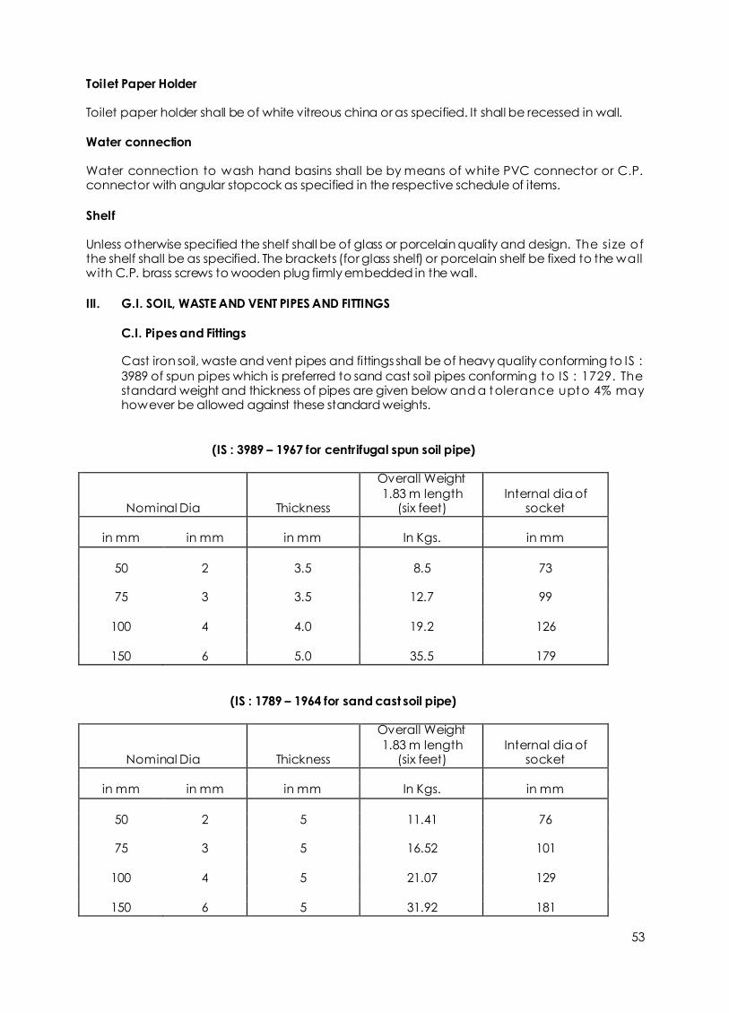
53
Toilet Paper Holder
Toilet paper holder shall be of white vitreous china or as specified. It shall be recessed in wall.
Water connection Water connection to wash hand basins shall be by means of white PVC connector or C.P. connector with angular stopcock as specified in the respective schedule of items.
Shelf
Unless otherwise specified the shelf shall be of glass or porcelain quality and design. The size of the shelf shall be as specified. The brackets (for glass shelf) or porcelain shelf be fixed to the wall with C.P. brass screws to wooden plug firmly embedded in the wall.
III. G.I. SOIL, WASTE AND VENT PIPES AND FITTINGS
C.I. Pipes and Fittings Cast iron soil, waste and vent pipes and fittings shall be of heavy quality conforming to IS :
3989 of spun pipes which is preferred to sand cast soil pipes conforming to IS : 1729. The standard weight and thickness of pipes are given below and a tolerance upto 4% may however be allowed against these standard weights.
(IS : 3989 – 1967 for centrifugal spun soil pipe)
Nominal Dia
Thickness
Overall Weight
1.83 m length (six feet)
Internal dia of socket
in mm in mm in mm In Kgs. in mm
50 2 3.5 8.5 73
75 3 3.5 12.7 99
100 4 4.0 19.2 126
150 6 5.0 35.5 179
(IS : 1789 – 1964 for sand cast soil pipe)
Nominal Dia
Thickness
Overall Weight
1.83 m length (six feet)
Internal dia of socket
in mm in mm in mm In Kgs. in mm
50 2 5 11.41 76
75 3 5 16.52 101
100 4 5 21.07 129
150 6 5 31.92 181

54
Laying
The pipes will be laid as described in the Schedule of Quantities and as shown on the Architects’ drawings.
Fixing The pipes and fittings shall be fixed to walls by using proper holder-bat clamps, i f di rected. The
pipes shall be fixed perfectly vertical or in an approved alignment. The spigot end shall about the shoulder of the socket and leave no annular space in between. Al l soi l and waste water pipes shall be carried up above the roof parapet wall and shall have A. C. Vent cowl.
Connection between main pipe and the branch pipes shall be made by using appropriate branches and bends invariably with access doors for cleaning.
Lead caulked joints
The annular space between the socket and spigot will be first wel l packed in with spun yarn soaked in bitumen and dried, leaving 25 mm from the lip of the socket for lead for pipes upto 100 mm dia and 38 mm depth for pipes of 150 mm dia. The joints may be leaded by using
proper leading rings or if they are not available by wrapping a ring of hemp rope covered with clay round the pipe at the end of socket, leaving a hole through which molten lead shal l be poured in.
Molten lead free from size or tin and thoroughly fluid shall be poured and each joint filled in one pouring. Before caulking, the projecting lead shall be removed by flat chisels and then the joint caulked round with proper caulking tools and a hammer of 1 to 1-1/2” Kg. In weight in such a
manner as to make the joint quite sound. The joint shall be left flush neat and even with the socket.
Testing All C. I. pipes and fittings including joints shall be tested by smoke test and left in working order
after completion.
Painting All exposed C. I. pipes and fittings shall be painted to match the colour on the surroundings with two coats of flat / enamel paint over a coat of approved primer. If directed, addit ional coats
shall be given at no extra cost.
IV. INTERNAL WATER SUPPLY
G. I. Pipes and Fittings The pipes shall be of the class specified in the Schedule of Quantities and shall be of galvanised steel, welded or scamless, screwed and socket and shall conform to IS : 1239. They shall be
manufactured by a firm of repute. All fittings shall be malleable iron galvanised fittings of approved best Indian make.

55
The details of pipes regarding nominal bore thickness and weight are given below :
Approx. outside
dia
Nominal bore Screwed and socket weight Per metre
Screwed and socket metre per 1000 Kgs.
in mm
in mm
in
nearest inch.
Light
Kgs.
Mediu
m Kgs.
Heavy
Kgs.
Light
Kgs.
Medium
Kgs.
Heavy
Kgs.
10.2 6 1/8 0.364 0.410 0.496 2724 2439 2016 13.5 8 ¼ 0.521 0.654 0.773 1919 1529 1294 17.2 10 3/8 0.680 0.858 1.03 1470 1166 971
21.3 15 ½ 0.961 1.23 1.46 1040 813 685 26.9 20 ¾ 1.42 1.59 1.91 704 629 524 33.7 25 1 2.03 2.46 2.99 493 407 334
42.4 32 1-1/4 2.61 3.17 3.87 383 316 258 48.3 40 1-1/2 3.29 3.65 4.47 304 274 224 60.3 50 2 4.18 5.17 6.24 239 193 160
76.1 65 2-1/2 5.92 6.63 8.02 169 151 125 88.9 80 3 6.98 8.64 10.3 143 116 98
101.6 90 3-1/2 8.92 9.90 11.8 112 101 84.7 114.3 100 4 10.2 12.4 14.7 98 80.6 68
139.7 125 5 --- 16.7 18.3 --- 59.9 54.6 165.1 150 6 --- 19.8 21.8 --- 50.5 45.9
Note : The above weights are for black pipe sand theoretical weight of galvanised pipes are 6% higher.
Laying and Fixing
Where pipes have to be cut or re-threaded ends shall be carefully filed out so that no obstruction to bore is offered.
For internal work all pipes and fittings shall be fixed truly vertical and horizontal either by m eans of standard pattern hold-bat clamps keeping the pipes 12 mm (1/2”) clear of the wall everywhere or concealed as directed.
For external work G. I. pipes and fittings shall be laid in trenches. The width of the trench shall be the minimum width required for the working. The pipes laid underground shall not be less than 60
cm. (2 ft.) from the ground level. They shall be painted with hot asphalt and wrapped with Hessian cloth and again painted with two coats of hot asphalt (pipes embedded in masonry / concrete shall be treated similarly). They shall be surrounded with 15 cm thick sand of approved
quality all round. The work of excavation and refilling shall be done as directed.
Painting All exposed pipes and fittings shall be painted with two coats of approved shade of flat enamel paint over a coat of approved primer and if directed, additional coat of paint shal l be given
without any extra cost.

56
Testing
All G. I. pipes and fittings shall be tested in an approved manner to ensure that pipes have proper threads and that proper materials such as white lead and hemp have been used in jointing. All leaky joints must be made leak proof by tightening or redoing at contractor’s
expenses.
Brass water fittings All brass water fittings shall be of approved and design and shall generally comply with the latest I. S. Specifications. They shall be fixed in the pipeline in a workmanlike manner and care shall be
taken to see that joints between fittings and pipes are made leak proof. The fi t tings and jo ints shall be tested in an approved manner to ensure that the joints are leak proof. The defect ive fittings and the joints shall be repaired to redon / replace at contractor’s expense.