Embed Size (px)
Citation preview

Page 1 of 26 Effective from …………. Draft Spec No. RDSO/2009/EM/SPEC/0010, Rev. ‗0‘
Prepared By
SE/EM
Checked By
ADE/EM
lR;eso t;rs
GOVERNMENT OF INDIA
MINISTRY OF RAILWAYS
DRAFT TECHNICAL SPECIFICATION
FOR
DESIGN, MANUFACTURE, TESTING SUPPLY AND COMMISSIONING OF SINGLE PHASE AND THREE PHASE
ELECTRONIC PREPAYMENT METERS
Draft Specification No. RDSO/2009/EM/SPEC/0010, Rev. ‗0‘
ISSUED BY -
RESEARCH DESIGNS & STANDARDS ORGANIZATION MANAK NAGAR, LUCKNOW - 226 011

Page 2 of 26 Effective from …………. Draft Spec No. RDSO/2009/EM/SPEC/0010, Rev. ‗0‘
Prepared By
SE/EM
Checked By
ADE/EM
I N D E X
Clause No. Description Page
1.0 FOREWORD 3
2.0 SCOPE
3
3.0 REFERENCE STANDARDS
3
4.0 CLIMATIC CONDITIONS
3
5.0 GENERAL REQUIREMENTS
4
6.0 TECHNICAL REQUIREMENT
9
7.0 SCHEDULE OF TESTS
19
8.0 O & M MANUAL
23
9.0 TRAINING
23
10.0 WARRANTY
23
11.0 SCOPE OF RAILWAY
24
12.0 BILL OF MATERIAL FOR THE REPAYMENT SYSTEM
24
13.0 ELIGIBILITY CRITERIA
25
14.0 INFRINGEMENT OF PATENT RIGHTS
26

Page 3 of 26 Effective from …………. Draft Spec No. RDSO/2009/EM/SPEC/0010, Rev. ‗0‘
Prepared By
SE/EM
Checked By
ADE/EM
DRAFT TECHNICAL SPECIFICATION OF DESIGN,
MANUFACTURE, TESTING SUPPLY & COMMISSIONING OF SINGLE PHASE & THREE PHASE ELECTRONIC
PREPAYMENT METERS 1. FOREWORD
Electromechanical meters have been used on Indian Railway on large scale. These meter suffer from inherent drawback of
low recording, tampering and poor accuracy etc. The problems have been partly solved with replacement with the
electronic meters. The issues relating to bill generations, distribution and collection from the vendors continues to be a cause of concern as it results in delayed collection with
very low yield rate. Prepayment meters are a step toward solving these problems and therefore considered a viable
option for the purpose of metering. 2. SCOPE:
The scope of this specification covers design, manufacture, testing and supply of single phase and Three Phase
electronic, keypad prepayment meters with split unit and provisions for TOD (Time of Day) tariff and R.T.C. (Real Time
Clock).
The requirements of the online Vending/Transaction system
to be provided for the prepayment metering system are also covered in the scope.
3. REFERENCE STANDARDS:
The meters with accuracy class–1.0 are required for measurement of Active Energy and shall conform to the Indian Standard IS 13779 and IEC 62052-11, IEC 62053-21.
4. CLIMATIC CONDITIONS:
4.1 The meter required to operate satisfactorily and continuously
with specified accuracy under hot, dusty and tropical
conditions and other climatic condition specified herein.

Page 4 of 26 Effective from …………. Draft Spec No. RDSO/2009/EM/SPEC/0010, Rev. ‗0‘
Prepared By
SE/EM
Checked By
ADE/EM
4.2 The climatic condition specified in this clause are average conditions, any specific conditions specified in the tender
documents shall override these.
Atmospheric
temperature
(a) Max. Ambient temperature 50°C
(b) Max. Daily average ambient temp. 40°C (c) Max. Soil temp. at cable depth 35°C
(d) Minimum temperature: - 5°C
(-10°C in J&K area. Also snow fall in certain areas during winter season)
Humidity 100% saturation during rainy season.
Reference site conditions
i) Ambient Temp. : 50° C ii) Humidity: 100% iii) Altitude: 1000m (2000 m in J & K area) above
mean sea level.
Rain fall Very heavy in certain areas.
Atmosphere
during hot weather
Extremely dusty and desert terrain in certain areas.
The dust concentration in air may reach a high value of 1.6 mg/m³. In many iron ore and coalmine areas, the dust concentration is very high affecting the filter and
air ventilation system.
Pollution level Humid and salt laden atmosphere with maximum. Ph value of 8.5, sulphate of 7mg per liter, max.
concentration of chlorine 6 mg per liter and maximum conductivity of 130 micro siemens/cm.
Wind speed High wind speed in certain areas, with wind pressure reaching 150kg/m²
5. GENERAL REQUIREMENTS:
5.1 General
i) Prepayment system is required whereby money is transferred
from a vending station to a customer meter by means of an
encrypted token. The system shall be managed centrally with the contained in the codes being encrypted by a secure
management system.

Page 5 of 26 Effective from …………. Draft Spec No. RDSO/2009/EM/SPEC/0010, Rev. ‗0‘
Prepared By
SE/EM
Checked By
ADE/EM
ii) The meter shall use keypad technology for the transfer of
credit from the vending system to the meter. The meter shall be single box design containing the measuring
element, main switch, display and keypad and comply with the requirements of the standards.
iii) The meter should be able to disconnect the load in case of exceeding the load limit. The load limit shall be defined in vending system and the same shall be transferred to the
meter through vend code.
iv) Meter shall be designed and constructed in such a way as to avoid introducing any danger in use and under normal conditions so as to ensure specially the following:
a) Personnel safety against electric shock
b) Personnel safety against effects of excessive temperature. c) Protection against penetration of solid objects,
dust and water. d) Protection against spread of fire.
v) All the material used in the manufacture of meters shall be of highest quality. The entire design and construction shall
be capable of withstanding stresses likely to occur in actual service and rough handling during transportation.
vi) All insulating material used in the construction of meter shall be non-hygroscopic non ageing and of tested quality and shall conform to tests as specified in relevant Standards.
vii) The meter shall be designed on application specific
integrated circuit and shall be manufactured using SMT (Surface Mount Technology) components and using micro-controller of reputed makes (e.g. Renesas, Texas
Instruments and NEC) which are to be approved by RDSO.
viii) The terminal block, the terminal cover and the meter case shall ensure reasonable safety against the spread of fire. They should not be ignited by thermic overload of live parts
in contact with them.

Page 6 of 26 Effective from …………. Draft Spec No. RDSO/2009/EM/SPEC/0010, Rev. ‗0‘
Prepared By
SE/EM
Checked By
ADE/EM
ix) The meter shall conform to the degree of protection IP 51 against ingress of dust, moisture and vermin.
x) All parts which are subject to corrosion under normal
working conditions shall be protected effectively. Any protective coating shall not be liable to change by ordinary handling due to exposure to air under normal working
conditions.
xi) The meters shall be designed such that their working remain
unaffected by electromagnetic interference, electrostatic discharges and high voltage transients as specified in
standard.
5.2 Constructional Requirements:
5.2.1 Meter Case:
i) The meter shall have completely insulated body and be of
wall mounted projected type. The meter shall have a case
made of unbreakable high grade fire resistant, reinforced polycarbonate or equivalent high grade engineering plastic which can be sealed in such a way that the internal parts of
the meter are accessible only after breaking the meter cover seals. The meter cover shall have at least two sealing screws,
each screw having the sealing holes. ii) The meter case shall have at least three mounting holes. Two
holes for mounting screws on the terminal block sealed beneath the terminal cover and one for hanging screw on the top.
5.2.2 Window
The meter cover shall be of high grade, fire resistant, reinforced polycarbonate or equivalent high grade
engineering plastic with one window made of UV stabilized, silicon coated polycarbonate or equivalent high grade
engineering plastic for reading the register. The window shall be integral part of the meter cover such that it can not be removed undamaged without breaking the meter cover.

Page 7 of 26 Effective from …………. Draft Spec No. RDSO/2009/EM/SPEC/0010, Rev. ‗0‘
Prepared By
SE/EM
Checked By
ADE/EM
5.2.3 Terminals & Terminals Block
i) The terminal block shall be made from best quality non-hygroscopic, fire retardant, reinforced polycarbonate (not
bakelite) or equivalent high grade engineering plastic which should form an extension of the meter case. It shall have terminal minimum internal diameter 5.5mm
ii) The meter shall be provided with fixed cage clamp, to
connect the cables. Each clamping screw shall engage at
least 3 threads in the terminals. The screws shall not have pointed edge at the end of thread. The clearance and creep
age distance of terminal block and tips between the terminal and the surrounding parts of metal enclosure shall be as per relevant IS standard.
iii) All parts of each terminal shall be such that the risk of
corrosion resulting from contact with any other metal part is minimized.
iv) Electrical connections shall be so designed that contact pressure is not transmitted through insulating material.
5.2.4 Terminal Cover :
i) The meter terminal Block shall be provided with an extended terminal cover with independent sealing arrangement in such a way that it shall cover the terminals, the conductor
fixing screws, the external conductors and their insulation i.e. no part of meter or cable accessories shall be visible from the front of the meter.
ii) When the meter is mounted, no access to the terminals shall
be possible without breaking the seal of the meter terminal cover.
5.2.5 Terminal Arrangement
A diagram of connections should be provided inside the cover of the terminal block. The terminal cover shall be extended such that when it is placed in position it is not
possible to approach the connections or connecting wires.

Page 8 of 26 Effective from …………. Draft Spec No. RDSO/2009/EM/SPEC/0010, Rev. ‗0‘
Prepared By
SE/EM
Checked By
ADE/EM
5.3 Tariff
Following are the features required in the meter for Tariff. It shall be possible to change all the tariff related parameters
through vend code.
i) Minimum charges: Using the online vending system it shall
be possible to define the minimum charge for the applicable tariff category. If the consumer consumes electricity equivalent of amount less than the minimum charge then at
the end of the billing period the meter shall deduct the difference of the minimum amount and the monthly
consumption (Amount).
ii) Fixed Charges: Meter shall be able to deduct fixed charges
on daily basis such as meter rent, sanctioned load based charges etc. The fixed charges shall be defined using the
online vending system.
iii) Time of Day (TOD) Tariff: The meter shall have facility for
recording and storing of TOD consumption on minimum Four Tariff Rates, per day basic. It should be possible to change the time period for TOD recordings through the
portable device or through vending system.
iv) Slab Tariff: The meter shall have capability for defining minimum four tariff slabs. It shall be possible to change the slabs through the portable device or through the online
vending system.
v) Tax/Duty: It shall be possible to define the tax percentage
through online vending system which has to be levied on the amount of the energy consumed.
vi) Rebate: The meter shall have facility to record the energy
consumption at the rates applicable after deducting the
rebate percentage on the energy consumption.
vii) Debt Management: It shall be possible to collect the debt from the consumers with the use of the online vending system. The debt percentage shall be defined in the vending
system.

Page 9 of 26 Effective from …………. Draft Spec No. RDSO/2009/EM/SPEC/0010, Rev. ‗0‘
Prepared By
SE/EM
Checked By
ADE/EM
6. TECHNICAL REQUIREMENT:
S.N. Particulars Single Phase Meter 3Phase Meter
1 VOLTAGE RATING
230 V (Phase-Neutral) 3 x 240 V (Phase-Neutral)
2 Rated Current
10- 60 Amp, 20 -80 Amps. 10-60 Amp,20-80Amp
3 VARIATION IN POWER SUPPLY
The meters shall be suitable for working satisfactorily with the
following power supply system variations
The meters shall be suitable for working satisfactorily with the
following power supply system variations
4 VOLTAGE RANGE
1. Specified Operating Range: 0.7 to 1.3 Vref. (-30% to +30%)
2. Operating voltage range for accuracy req:0.85 to
1.15 Vref i.e. –15% to + 15%
1. Specified Operating Range: 0.7 to 1.3 Vref. (-30% to +30%)
2. Operating voltage range for accuracy req:0.85 to
1.15 Vref i.e. –15% to + 15%
5 FREQUENCY VARIATION
The standard reference frequency for performance
shall be 50Hz with tolerance + 5%.
The standard reference frequency for performance
shall be 50Hz with tolerance + 5%.
6 POWER
CONSUMPTION
i) VOLTAGE CIRCUIT: The
active, apparent Power consumption in voltage
circuit including the power supply of the meter at reference voltage, reference
temperature and reference frequency shall be within
limits as specify in relevant BIS standard.
ii) CURRENT CIRCUIT: The apparent Power taken by each current circuit at
basic current, reference frequency and reference temperature shall be within
limits as specify in relevant BIS standard.
VOLTAGE CIRCUIT:
The active, apparent Power consumption in voltage
circuit including the power supply of the meter at reference voltage, reference
temperature and reference frequency shall be within
limits as specify in relevant BIS standard.
CURRENT CIRCUIT: The apparent Power taken by each current circuit at
basic current, reference frequency and reference temperature shall be within
limits as specify in relevant BIS standard.

Page 10 of 26 Effective from …………. Draft Spec No. RDSO/2009/EM/SPEC/0010, Rev. ‗0‘
Prepared By
SE/EM
Checked By
ADE/EM
6.1 Display Features 6.1.1 Single and three phase Meter:
The meter has Keypad buttons which enables the user to
view various displays available on the meter. The displays on various keys shall be as follows:
i) Days Left (based on consumption of last seven days) ii) Value of recent consumption
iii) The currently active rates, the prices charged for consumption at each rate, and the number of units consumed at each rate and the daily charges
iv) Last 5 Codes v) These displays show the ―Authenticated Billing Code‖# and
the total amount vended
vi) These displays show the current load and the cost of that load
vii) Daily charges are shown viii) Maximum Demand with occurrence of time ix) kWH unit
x) Date/Time and Retained credit codes xi) Key code mode
xii) Scroll back button xiii) # ―Authenticated Billing Code‖: The meter should display the
20 digit authenticated meter reading code on key 5. The full
20 digit token shall contain the following frozen value at midnight (00:00 Hr) of month end.
xiv) 5 digit cumulative kWh energy register.
xv) Date of frozen data. xvi) Credit balance, it may be positive or negative.
7 STARTING
CURRENT
The meter should start
registering the energy at 0.2% of minimum of the rated current ( i.e. 10A or
20A).
The meter should start
registering the energy at 0.2% of minimum of the rated current ( i.e. 10A or
20A).
8 ACCURACY Class of accuracy of meter
shall be 1.0 and shall confirm to accuracy requirement as per specify
BIS/IEC standard
Class of accuracy of meter
shall be 1.0 and shall confirm to accuracy requirement as per specify
BIS/IEC standard

Page 11 of 26 Effective from …………. Draft Spec No. RDSO/2009/EM/SPEC/0010, Rev. ‗0‘
Prepared By
SE/EM
Checked By
ADE/EM
xvii) The tamper flag, which only indicates whether there is any tamper or not.
6.2 Tamper and Fraud Protection
6.2.1 Single Phase Meter
The meter shall operate normally under the following conditions:
i) Phase current reversal: The meter shall record forwarded energy.
iii) Neutral current reversal: The meter shall record forwarded
energy.
iii) Phase and neutral interchange: The meter shall record
forwarded energy.
iv) The meter shall operate normally in case the phase and
neutral are swapped with neutral connected to earth.
v) In case the neutral is opened with earth load connected,
partial phase by pass or full phase bypass the energy shall be recorded on the wire which has higher current recording.
Such tampers shall be logged in the memory of the meter.
vi) The metering system shall be provided with adequate
magnetic shielding so that any external magnetic field (AC Electro Magnet or DC Magnet) as per the values specified in standard applied on the metering system shall not affect the
proper functioning and recording of energy as per error limits prescribed by standard.
vii) In addition to this the meter shall be immune to 0.5Tesla
permanent magnet and there shall be no effect on switch
and measurement on applying this magnet. However, if tamper logging is required for magnet influences than in
case the magnetic influences effects the metering it shall be logged as tamper & meter shall record energy as per standards.
Page 12 of 26 Effective from …………. Draft Spec No. RDSO/2009/EM/SPEC/0010, Rev. ‗0‘
Prepared By
SE/EM
Checked By
ADE/EM
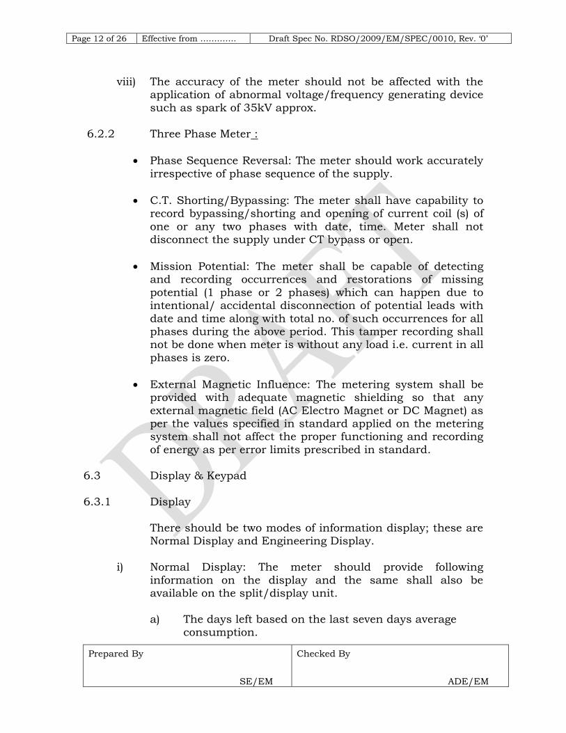
viii) The accuracy of the meter should not be affected with the application of abnormal voltage/frequency generating device
such as spark of 35kV approx.
6.2.2 Three Phase Meter :
Phase Sequence Reversal: The meter should work accurately
irrespective of phase sequence of the supply.
C.T. Shorting/Bypassing: The meter shall have capability to record bypassing/shorting and opening of current coil (s) of
one or any two phases with date, time. Meter shall not disconnect the supply under CT bypass or open.
Mission Potential: The meter shall be capable of detecting and recording occurrences and restorations of missing
potential (1 phase or 2 phases) which can happen due to intentional/ accidental disconnection of potential leads with
date and time along with total no. of such occurrences for all phases during the above period. This tamper recording shall not be done when meter is without any load i.e. current in all
phases is zero.
External Magnetic Influence: The metering system shall be provided with adequate magnetic shielding so that any
external magnetic field (AC Electro Magnet or DC Magnet) as per the values specified in standard applied on the metering system shall not affect the proper functioning and recording
of energy as per error limits prescribed in standard. 6.3 Display & Keypad
6.3.1 Display
There should be two modes of information display; these are Normal Display and Engineering Display.
i) Normal Display: The meter should provide following
information on the display and the same shall also be available on the split/display unit.
a) The days left based on the last seven days average consumption.

Page 13 of 26 Effective from …………. Draft Spec No. RDSO/2009/EM/SPEC/0010, Rev. ‗0‘
Prepared By
SE/EM
Checked By
ADE/EM
b) Connected Load and the Load cost in Rs/hr. c) Consumption history for previous day, previous week,
previous month and subsequent last twelve months. d) Tariff details such as the applicable tariff rates,
fixed/standing charge, minimum charges and the applicable tax.
e) Last five vend codes entered.
f) Total credit added till date. g) MD information along with date and time.
ii) Engineering Display: This display shall be available only upon the application of Valid Codes on the meter, and shall
enable the display of the following:
iii) Software version.
iv) All the limiting parameters value, such as Load limit, current
limit and emergency credit limit. v) Switch operation counts.
The switch shall be used to disconnect customers depending on their load demand or the state of their
account and shall be capable of operating over the life of the meter.
6.3.2 LCD Unit
The display unit of meter shall be Pin type built-in liquid crystal display. The measured value(s) shall be displayed on minimum six digit Liquid Crystal display (LCD) display unit,
having minimum character size of 8mm X 4mm. When the meter is not energized, the display need not be visible. Each
display shall be retained for a minimum period of 2s. 6.3.3 Keypad
The keypad buttons shall have numbers/letters on them,
which shall be clearly visible and resistant to wear. The layout of the numbering shall be same as that used on standard telephones for numbers ‗1‘ through ‗9‘ and buttons
such as ‗*‘, ‗0‘, and ‗#‘. Button ‗5‘ shall have some form of

Page 14 of 26 Effective from …………. Draft Spec No. RDSO/2009/EM/SPEC/0010, Rev. ‗0‘
Prepared By
SE/EM
Checked By
ADE/EM
physical identification (raised printing or a pip) to aid customers with poor sight.
The keypad IP rating shall be adequate to permit use with
moist or wet hands whilst ensuring the safety of the user and preventing ingress of dirt and water to the unit.
The keypad buttons shall provide audible feedback when pressed with differing tones to distinguish between valid and invalid entry...
The entry of codes for credit or commands associated with
programming functions such as tariff change shall be via numeric codes. Code encryption/decryption must be carried out using an internationally recognized standard (i.e. Triple
DES).
The meter shall permit a time delay of up to 20 seconds between keystrokes.
The meter has Keypad buttons which enables the user to view various displays available on the meter.
6.4 Communication Capability
The meter shall be provided with an optical communication port (Compatible to RS232). It shall be possible to read the meter through the optical port with held hand device
6.5 Meter Reading:
It shall be possible to read the prepayment meters and minimum following information shall be available in meter
reading data.
The transaction history data with date and time.
All the events history with time based and category based
information.
Tariff details including the TOD tables, slab tables and
information about the current active rate price.
Monthly history and consumption data of the energy
consumed for last twelve months.
ABC codes.

Page 15 of 26 Effective from …………. Draft Spec No. RDSO/2009/EM/SPEC/0010, Rev. ‗0‘
Prepared By
SE/EM
Checked By
ADE/EM
All the account related information like meter credit,
emergency credit details, minimum charge and fixed charges value.
All the limiting parameters shall also be available in meter
reading.
6.6 Name Plate Marking
The name plate shall have following markings which shall be indelible, distinct and readable from outside the meter:—
Manufacturer's name and/or trade mark and the place of manufacture
Designation of type
The no. of phases and no. of wires for which the meter is
suitable for
The manufacturer‘s serial number and year of manufacture
Reference voltage
The basic current and the maximum current
The principal unit in which the meter reads
Meter constant
Class index of the meter
Reference Frequency
6.7 Remote Display Unit:
The meter shall be supplied with a separate display unit.
The display unit shall be powered up from the meter
The display unit shall have a LCD display similar to that of
the meter
The display unit shall have a key pad to enter the code. The
keypad should be similar to the keypad available on the meter
The display unit shall have an RJ11 connection port to connect to the meter
The distance between the display unit and the prepayment meter shall be upto 100 meters
The display unit and energy meter shall be connected using a 4 wire connection cable (Similar to telephone cable).
The display unit shall have a buzzer to generate alarm signal in case of low credit and overload.

Page 16 of 26 Effective from …………. Draft Spec No. RDSO/2009/EM/SPEC/0010, Rev. ‗0‘
Prepared By
SE/EM
Checked By
ADE/EM
6.8 Vending System Requirement:
This section specifies the requirements of the vending system for currency based prepayment metering solution.
The meter shall work on the latest currency transfer keypad
technology supported by an online vending system. The keypad technology is future proof, cost effective and in this
communication age, enables consumers to buy electricity over the multiple vending options like Railway billing centers, Railway website, through third party POS providers and SMS
based vending. Additional options shall also be supported which shall need the discussion with the Railway as per the mutual agreement i.e. vending through mobile phones, IVR,
bank ATM, retail vending stations etc thus provides multiple options to buy electricity.
The vending system shall use Triple Data Encryption
Standard (Triple DES), i.e. it provides three levels of encryption for the vend code. The code shall be meter specific and can‘t be used in any other meter. Triple DES is widely
used in banking systems worldwide due to the high level of security provided by the algorithm.
The Redundancy in the vending system shall be covered. The
back up with the site server shall be given to overcome the problem.
The necessary licensed Software for each Vending Station at Railway billing centre shall be provided by bidder.
The vending station shall be placed at the billing stations of Railway for which necessary office space, electricity etc. and
furniture for this system shall be provided by Railway. Cash shall be collected by Railway staff; upon the advice of the designated staff the vend terminal / personal computer shall
generate a token to transfer the credit to the energy meter. The token shall be printed using the printer attached to the
personal computer.
The vending system shall be the online vending system from
where the vend codes shall be issued. It shall be possible to

Page 17 of 26 Effective from …………. Draft Spec No. RDSO/2009/EM/SPEC/0010, Rev. ‗0‘
Prepared By
SE/EM
Checked By
ADE/EM
provide various vending options like SMS based vending, web based vending and POS terminals based vending.
A client system shall be provided in the project monitoring
center to produce the MIS reports and defining the customers in the database as mentioned in this specification.
The steps of vending shall be as under:
On receipt of the vend request the system shall have a provision to ascertain the identity of the consumer. The keys to identify the
consumer shall be the meter serial number or consumer premise number.
The vend terminal shall send the request to a central database that
shall authenticate the transaction and generate an encrypted code.
In order to provide maximum security to the system the encryption
shall not be done on the vend terminal.
On receipt of each request the vend terminal shall connect to the central database and get the code generated.
The code hence generated shall be printed on paper using the
attached printer.
The consumer shall pay the money at the vend terminal, this information when fed to the vend terminal shall be send to the
central database that shall encrypt the token using Triple DES encryption algorithm.
6.9 Data Monitoring Centre (DMC):
The DMC shall be a part of the vending system which shall have capability to interface with the central database and produce the management reports as detailed in the
specification. It shall manage all administrative data, including settings of system accounts, tariffs, meter and Consumer data. It shall also provide reporting system for
system analysis.

Page 18 of 26 Effective from …………. Draft Spec No. RDSO/2009/EM/SPEC/0010, Rev. ‗0‘
Prepared By
SE/EM
Checked By
ADE/EM
Various tasks that should be performed from the DMC are outlined below:
1. Consumer Database Management
1.1 Entry of new consumers and their details 1.2 Existing consumer database
2. Meter Database Management: Uploading of meter database
3. Tariff Management 3.1 Tariff structure definition
3.2 Rate Price definition 3.3 Tariff category 3.4 Tax percentage
3.5 Fixed Charge value 3.6 Minimum charge value
3.7 Slab reset period 3.8 Tariff change administration
4. Limit Parameters management 4.1 Define Load Limit 4.2 Current Limit value
4.3 Emergency Credit
5. Debt (previous charges) Management
6. Transaction management :
6.1 Cash vend transaction 6.2 Retained credit transaction 6.3 Refund Money Transaction
6.4 Previous Charge Transaction
7. Reports 7.1 Debt collection and outstanding report 7.2 Tax and duties accounts report
7.3 Customer‘s Vend Report
8. Import of data by the vending station from the master station / Export of data by the main station to the vending stations:
8.1 Import of data from Comma separated
values(CSV) format files 8.2 Export of data in CSV format.

Page 19 of 26 Effective from …………. Draft Spec No. RDSO/2009/EM/SPEC/0010, Rev. ‗0‘
Prepared By
SE/EM
Checked By
ADE/EM
9. Message Management 9.1 Entry of System Message
9.2 Entry of Customer Specific Messages 9.3 Entry of Predefined Messages
10. User Security Management
10.1 Group rights definition
10.2 Entry of system users and allocation of group rights
6.10 Security Aspect
The vending system shall be a sophisticated system with reliable security features.
i) The token created for particular meter with the defined tariff shall not be used for any other meter.
ii) The meter shall accept the valid token only once. The token generated shall be meter specific and shall be used only on the particular meter for which it is intended.
iii) The token in not be reusable v) The token shall be re-issued in case of losing the same. vi) Whenever a tariff change takes place the token should not
accept new vends without entering the new tariff. vii) The token generated shall be authenticated as well as
encrypted so that no decoding is possible. viii) The Vending system must be certified to ISO/IEC 27001
which is the only auditable international standard which
defines the requirements for an Information Security Management System (ISMS). The standard is designed to ensure the selection of adequate and proportionate security
controls.
7.0 SCHEDULE OF TESTS: 7.1 General
7.1.1 Prototype inspection shall be done by RDSO, Lucknow, and
after successful completion of all the type and routine tests as per this specification, prototype approval shall be issued. After approval of prototype, acceptance & routine tests on
the balance quantity shall be done by the authorized representative of the Indian Railways as per purchase order.

Page 20 of 26 Effective from …………. Draft Spec No. RDSO/2009/EM/SPEC/0010, Rev. ‗0‘
Prepared By
SE/EM
Checked By
ADE/EM
7.1.2 Only after all the designs and drawings have been approved
and clearance given to this effect by RDSO, the manufacturer shall take up manufacture of the prototype for
inspection/testing by RDSO. It is to be clearly understood that any changes to be done on the prototype as required by RDSO, the same shall be done expeditiously.
7.1.3 Prior to giving a call for inspection and testing of the
prototype, the successful tenderer/manufacturer shall
submit a detailed test schedule consisting of test procedures, schematic circuit diagrams, items/parameters to be checked
and values required as per specification for each of the tests and the number of days required to complete all the tests at one stretch. The schedule shall also indicate the venue of
each of the tests. Once the schedule is approved, the tests shall invariably be done accordingly. However, during the
process of type testing or even later, the DG/EM/RDSO, Lucknow, reserves the right to conduct any additional test(s), besides those specified herein, on any equipment/item so as
to test the equipment/item to his satisfaction or for gaining additional information and knowledge.
7.1.4 In case any dispute or disagreement arises between the successful tenderer/manufacturer and the representative of
the DG/EM/RDSO, Lucknow, during the process of testing as regards the procedure for type tests and/or the interpretation and acceptability of the results of type tests, it
shall be brought to the notice of the DG/EM/RDSO, Lucknow, as the case may be whose decision shall be final and binding. Only after the prototype of the equipment is
manufactured and ready in all respects, shall the successful tenderer/manufacturer give the actual call for the inspection
and testing with at least 30 days notice for the purpose.
7.1.5 The tests shall be conducted on the prototype unit at the
works of the manufacturer or at any NABL approved testing house or laboratory in the presence of DG/EM/RDSO,
Lucknow, or his authorized representative. The prototype shall be complete in all respects, as would be supplied if it had passed the tests. The tests shall be conducted to the
governing specification and as modified or amplified herein.

Page 21 of 26 Effective from …………. Draft Spec No. RDSO/2009/EM/SPEC/0010, Rev. ‗0‘
Prepared By
SE/EM
Checked By
ADE/EM
7.1.6 For tests conducted in the laboratories of Central Power Research Institute, Bhopal/ Bangalore, Electrical Research
Development Association, Vadodara or any such testing house or laboratory, a certificate to the effect that the
equipment has passed the tests as per specification shall be obtained by the manufacturer and submitted to the DG/EM/RDSO, Lucknow. Full details of the tests and test
parameters shall be furnished along with the test reports. 7.1.7 Irrespective of the cables being a standard/proven item of
the manufacturer for which type tests have already been conducted and the test results are available, the type tests
shall nevertheless, be conducted for the procurement against this specification. The routine/acceptance/type tests to be carried out.
7.1.8 Six copies of the following test certificates shall be submitted
to the Purchaser for record:-
(i) Type test certificate as issued by RDSO.
(ii) Acceptance test certificate.
(iii) Routine test certificates.
7.1.9 Test certificates shall be completed with all the results. Purchaser‘s approval shall be obtained before dispatch of meters from the works.
7.1.10 Manufacturer shall advise the purchaser one month in
advance when the cable shall be ready for inspection and
tests, so that the latter‘s representatives may be deputed to witness the test(s). No material shall be shipped or
dispatched until inspection and tests upto the satisfaction of the purchaser have been carried out. Such inspection and approval shall not relieve the manufacturer from full
responsibility as defined in scope to the requirement of the specification nor prejudice any claim, right or privilege which
the purchaser may have because of the use of defective or unsatisfactory equipment.

Page 22 of 26 Effective from …………. Draft Spec No. RDSO/2009/EM/SPEC/0010, Rev. ‗0‘
Prepared By
SE/EM
Checked By
ADE/EM
7.2 Tests
The tests shall be carried out as per the stipulations of IEC/IS. The test plan shall be got approved by RDSO before
carrying out the test. Following tests shall be carried out on the system as a minimum:
S. No.
Name of test
Reference clause of
IEC/IS
Type Test
Routine Test
Acceptance Test
1 Impulse Voltage test 12.7.6.2
2 AC high voltage test 12.7.6.3
3 Insulation test 12.7.6.4
4 Test on limit of errors 11.11
5 Interpretation of test
results
12.16
6 Test of meter
constant
12.15
7 Test of starting
Condition
12.14
8 Test of NO-Load condition
12.13
9 Test of ambient temp. influence
12.12
10 Test of repeatability of error
12.17
11 Test of influence quantities
12.11
12 Test of power consumption test
12.7.1
13 Test of influence of supply voltage
12.7.2
14 Test of influence of short time Over-currents
12.7.3
15 Test of influence of self- heating
12.7.4
16 Test of influence of heating
12.7.5
17 Test of influence of immunity to earth
fault
12.8
Page 23 of 26 Effective from …………. Draft Spec No. RDSO/2009/EM/SPEC/0010, Rev. ‗0‘
Prepared By
SE/EM
Checked By
ADE/EM
S.
No.
Name of test
Reference
clause of IEC/IS
Type
Test
Routine
Test
Acceptance
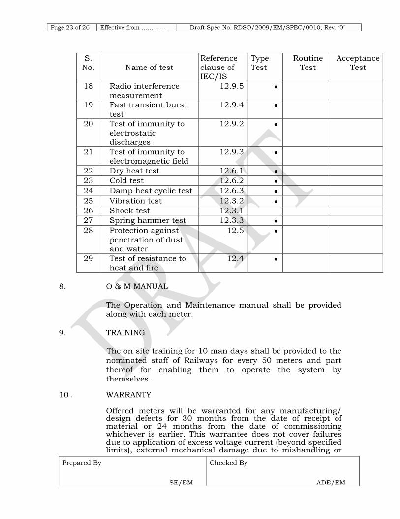
Test
18 Radio interference
measurement
12.9.5
19 Fast transient burst
test
12.9.4
20 Test of immunity to
electrostatic discharges
12.9.2
21 Test of immunity to electromagnetic field
12.9.3
22 Dry heat test 12.6.1
23 Cold test 12.6.2
24 Damp heat cyclie test 12.6.3
25 Vibration test 12.3.2
26 Shock test 12.3.1
27 Spring hammer test 12.3.3
28 Protection against
penetration of dust and water
12.5
29 Test of resistance to
heat and fire
12.4
8. O & M MANUAL
The Operation and Maintenance manual shall be provided along with each meter.
9. TRAINING The on site training for 10 man days shall be provided to the
nominated staff of Railways for every 50 meters and part thereof for enabling them to operate the system by
themselves. 10 . WARRANTY
Offered meters will be warranted for any manufacturing/ design defects for 30 months from the date of receipt of material or 24 months from the date of commissioning whichever is earlier. This warrantee does not cover failures due to application of excess voltage current (beyond specified limits), external mechanical damage due to mishandling or

Page 24 of 26 Effective from …………. Draft Spec No. RDSO/2009/EM/SPEC/0010, Rev. ‗0‘
Prepared By
SE/EM
Checked By
ADE/EM
wrong use of the equipment. Our Warrantee is limited to repair/ replacement of the product only. Our guarantee covers design manufacturing and workmanship defects only and is limited to repair / replacement.
The warranty does not cover any damage caused by
accident, misuse, neglect, alteration, modification or substitution of any of the Items, or any attempt to fiddle with the items by unauthorized personnel, storm, hitting by trucks or any external forces etc.
Warranty also does not cover for theft of any item after
handing over by us to you.
Under no circumstance, shall the contractor be liable for any consequential or resulting injury or loss, damage of expense
directly or indirectly from the use of the items supplied by us.
11. SCOPE OF RAILWAY
Railway shall deliver the following: All the hardware mentioned in the bill of material and space
to install the hardware to operate the vending stations shall be responsibility of Railway. Internet connectivity among the
different vending stations shall be responsibility of Railway.
12. BILL OF MATERIAL FOR THE REPAYMENT SYSTEM
S. N. Component Specification Quantity
1 Business Desktop
PC
Intel Core 2 Duo Processor E
4400, 20 GHz 2x I-MB 1.2 cache ( 1-MB each
core), 800 MHz FSB Intel Q965/ICH8 chipset motherboard
17 inch (43.1 cm) CRT colour monitor
Intel Graphics Media Accelerator GMA 3000 with DVMT 3.0, 128 MB Shared
Video Memory 10/100/1000 Ethernert LAN card
Depends on
No. of Vending stations.

Page 25 of 26 Effective from …………. Draft Spec No. RDSO/2009/EM/SPEC/0010, Rev. ‗0‘
Prepared By
SE/EM
Checked By
ADE/EM
2 UPS,1KVA
UNINTERRUPTIBLE POWER SUPPLY (UPS)
Depends on
No. of Vending stations.
3 Receipt printer POS receipt printer –Dot matrix – 9 pin – Two color
(monochrome) Print Speed - lines/sec – 16 cpi Wired Interface - Parallel
Resolution - 17.8 cpi Columns - 33,35,40,42
Features - Auto cutter
Depends on
No. of Vending
stations.
4 Report printer Laser – Monochrome Print speed - 18 pages/min –
B/W A4 (8.25 in x 11.7 in) Resolution - 1200 dpi x 1200
dpi Processor - 266 MHz RAM Installed - 8 MB
Depends on
No. of Vending stations.
6 RJ11 communication
cable
4 core cable As per in home display
unit quantity
7 Prepaid Meter with
display unit
As per above
8 Software
13. ELIGIBILITY CRITERIA
i) Only Manufacturers are allowed to quote.
ii) Bidder shall have ISO 9000:2001 certification. iii) The bidder shall be an original Indian Electronic / static key
pad technology based energy prepayment meter manufacturer and shall have designed, manufactured &
tested experience for at least three years in manufacturing of prepayment meter.
iv) The bidder shall have valid BIS Certification of relevant ISS for the offered meters. Type test of the same shall be submitted at the time of submission of offer.

Page 26 of 26 Effective from …………. Draft Spec No. RDSO/2009/EM/SPEC/0010, Rev. ‗0‘
Prepared By
SE/EM
Checked By
ADE/EM
14.0 INFRINGEMENT OF PATENT RIGHTS
14.1 Indian Railways shall not be responsible for infringement of
patent rights arising due to similarity in design, manufacturing process, use of similar components in the design & development of this item and any other factor not
mentioned herein which may cause such a dispute. The entire responsibility to settle any such disputes/matters lies with the manufacturer/ supplier.