Embed Size (px)
Citation preview

NTPC FEROZ GANDHI UNCHAHAR 1X500MW THERMAL POWER STATION, STAGE-IV
TECHNICAL SPECIFICATION
FOR
LUBE OIL TRANSFER PUMPS
SPECIFICATION NO.: PE-TS-401-567-A001
BHARAT HEAVY ELECTRICALS LTD POWER SECTOR
PROJECT ENGINEERIING MANAGEMENT PPEI, NOIDA-INDIA
Page 1 of 70

TECHNICAL SPECIFICATION FOR
LUBE OIL TRANSFER PUMPS
1 X 500 MW NTPC FGUTPP STAGE IV
SPECIFICATION NO. PE-TS-401-567-A001
REVISION 00 DATE:25.06.2014
PEM
-666
6-0
��
INDEX���
S.�No.� DESCRIPTION� VOLUME/�SECTION�
PAGE�NO.�
1.� Preamble� � 3�2.� Intent�of�Specification� II�B�/�A� 5�3.� Project�information� II�B�/�B� 8�4.� Specific�Technical�Requirements�� II�B�/�C� �� a. Scope�of�Work� � 12�� b. Datasheet�A�for�Lube�oil�transfer�pumps� � 15�� c. Special�Technical�Requirement�Electrical� � 16�� d. ANNEXURE�I�(�Electrical�Scope)� � 18�� e. NTPC�specification�for�motor� � 19�� f. Datasheet�A�for�electrical�motor� � �5.� Technical�Specification�of�Equipment� II�B�/�D� �� a. General�Technical�Specification�for�Lube�Oil�Pumps�� � 30�� b. General�Technical�Requirement�for�LV�Motors� � 40�� c. Quality�Plan�for�Lube�Oil�Pumps��� � 46�� d. Quality�Plan�for�Basket�(�Simplex�&�Duplex)�Strainer�� � 50�� e. Quality�Plan�for�MOTOR� � 53�6.� Technical�Schedules�/�Datasheets� III� �
� a. Pre��bid�clarification�schedule�� � 56�
� b. Deviation�Schedule� � 57�� c. Data�Sheet�for�Lube�Oil�Pumps� � 58�� d. Data�Sheet�C�for�Motor� � 63�� e. ANNEXURE�II�(Electrical�Load�data�format)� � 65�� f. ANNEXURE�III�:Drawings/Documents�required�
during�detail�engineering� � 66�
� g. Compliance�cum�Confirmation�certificate�� � 68�� h. Suggestive�Price�format� � 70�
Page 2 of 70

SPEC. NO. PE-TS-401-567-A001 TECHNICAL SPECIFICATION FOR
LUBE OIL TRANSFER PUMPS REV. NO. 00 DATE : 25.06.2014
PREAMBLE
1.0 The Tender document contains three (3) volumes. The bidder shall meet the requirements of all the three volumes.
1.1 Volume –I CONDITIONS OF CONTRACT
This consists of four parts as below:
Volume - I A : This part contains instructions to bidders for making bids to BHEL.
Volume - I B : This part contains general commercial conditions of the tender and include provision that vendor shall be responsible for the quality of item supplied by their sub-vendors.
Volume - I C : This part contains special conditions of contract.
Volume - I D : This part contains commercial conditions for erection and commissioning of site work, as applicable.
1.2 Volume- II - TECHNICAL SPECIFICATIONS
Technical requirements are stipulated in Volume II which comprises of:
Volume - II A : General Technical Requirements - NA
Volume - II B : Technical specification including drawings, if any
1.2.1 Volume - II B:
This volume is sub-divided into following sections:
Section - A : This section outlines the scope of enquiry.
Section - B : This section provides “Project Information”
Section - C : This section indicates technical requirements specific to the contract, not covered in Section-D.
Section - D : This section comprises of technical specifications of equipments complete with their data sheets, if any.
Page 3 of 70

SPEC. NO. PE-TS-401-567-A001 TECHNICAL SPECIFICATION FOR
LUBE OIL TRANSFER PUMPS REV. NO. 00 DATE : 25.06.2014
1.2.2 Volume - III TECHNICAL SCHEDULES
This volume contains technical schedules which are to be duly filled by the bidder and the same shall be furnished with the technical bid, as applicable.
Page 4 of 70

TECHNICAL SPECIFICATIONS
FOR
LUBE OIL TRANSFER PUMPS
SECTION – A
(INTENT OF SPECIFICATION)
BHARAT HEAVY ELECTRICALS LTD POWER SECTOR PROJECT ENGINEERING MANAGEMENT
PPEI, NOIDA-INDIA
Page 5 of 70

SPECIFICATION NO. PE-TS-401-567-A001
TECHNICAL SPECIFICATION FOR VOLUME II B
LUBE OIL PUMPS SECTION A
REV 00 DATE - 25.06.2014
PEM
-666
6-0
1.0 SCOPE OF INQUIRY / INTENT OF SPECIFICATION
1.1 The specification is intended to cover design, engineering, manufacture, inspection and testing at vendor's/ sub-vendor’s works, proper packing, delivery at site including freight, painting etc. for Lubeoil pumps as per details in different sections / volumes of this specification.
1.2 The contractor shall be responsible for providing all material, equipment & services, which are required to fulfil the intent of ensuring operability, maintainability, reliability and complete safety of the complete work covered under this specification, irrespective of whether it has been specifically listed herein or not. Omission of specific reference to any component / accessory necessary for proper performance of the equipment shall not relieve the contractor for the responsibility of providing such facilities to complete the supply of Lube oil pumps to customer.
1.3 It is not the intent to specify herein all the details of design and manufacture. However, the equipment shall conform in all respects to high standards of design, engineering and workmanship and shall be capable of performing the required duties in a manner acceptable to purchaser who will interpret the meaning of drawings and specifications and shall be entitled to reject any work or material which in his judgement is not in full accordance herewith.
1.4 The extent of supply under the contract includes all items shown in the drawings, notwithstanding the fact that such items may have been omitted from the specification or schedules. Similarly, the extent of supply also includes all items mentioned in the specification and /or schedules, notwithstanding the fact that such items may have been omitted in the drawing.
1.5 The general term and conditions, instructions to tenderer and other attachment referred to elsewhere are made part of the tender specification. The equipment materials and works covered by this specification are subject to compliance to all attachments referred to in the specification. The bidder shall be responsible for and governed by all requirements stipulated herein.
1.6 While all efforts have been made to make the specification requirement complete & unambiguous, it shall be bidders’ responsibility to ask for missing information , ensure completeness of specification, to bring out any contradictory / conflicting requirement in different sections of the specification and within a section itself to the notice of BHEL and to seek any clarification on specification requirement in the format enclosed under Vol-III of the specification within 10 days of receipt of tender documents. In absence of any such clarifications, in case of any contradictory requirement, the more stringent requirement as per interpretation of Purchaser/Customer shall prevail and shall be complied by the bidder without any commercial implication on account of the same. Further in case of any missing information in the specification not brought out by the prospective bidders as part of pre-bid clarification, the same shall be furnished by Purchaser/ Customer as and when brought to their notice either by the bidder or by purchaser/ customer themselves. However, such requirements shall be binding on the successful bidder without any commercial & delivery implication.
1.7 The bidder’s offer shall not carry any sections like clarification, interpretations and /or assumptions.
1.8 Deviations, if any, should be very clearly brought out clause by clause in the enclosed schedule; otherwise, it will be presumed that the vendor's offer is strictly in line with NIT specification.
1.9 In case all above requirements are not complied with, the offer may be considered as incomplete and would become liable for rejection.
Page 6 of 70

SPECIFICATION NO. PE-TS-401-567-A001
TECHNICAL SPECIFICATION FOR VOLUME II B
LUBE OIL PUMPS SECTION A
REV 00 DATE - 25.06.2014
PEM
-666
6-0
1.10 Unless specified otherwise, all through the specification, the word contractor shall have same meaning as successful bidder /vendor and Customer/ Purchaser/Employer will mean BHEL and /or BHEL’s customer including their consultant as interpreted by BHEL in the relevant context.
Page 7 of 70

TECHNICAL SPECIFICATIONS
FOR
LUBE OIL TRANSFER PUMPS
SECTION – B
(PROJECT INFORMATION)
BHARAT HEAVY ELECTRICALS LTD POWER SECTOR PROJECT ENGINEERING MANAGEMENT
PPEI, NOIDA-INDIA
Page 8 of 70

Page 9 of 70

Page 10 of 70
TECHNICAL SPECIFICATIONS
FOR
LUBE OIL TRANSFER PUMPS
SECTION – C (Specific Technical Requirements)
BHARAT HEAVY ELECTRICALS LTD POWER SECTOR PROJECT ENGINEERING MANAGEMENT
PPEI,NOIDA-INDIA
Page 11 of 70

TITLE SPECIFICATION NO. PE-TS-401-567-A001
TECHNICAL SPECIFICATION VOLUME II B
FOR SECTION C
LUBE OIL PUMPS REV 00 DATE : 25.06.2014
(Specific Technical Requirements)
PEM
-666
6-0
�1.0����SCOPE�OF�WORK����1.1� � Design,� engineering,� manufacturing,� inspection� and� testing� at� manufacturer’s� works,� painting,�
supply/delivery�duly�packed�at�project� site� for� � � pump�&�motor� set�duly� coupled�and�unitised�on� a�common�base�frame�with�coupling�guard,�foundation�bolts,�flanges,�companion�flanges�with�nuts�bolts�and�gaskets,�drip�pan�with�plugged�draining�arrangement,� strainer�with� flanges,� companion� flanges,�nuts,� bolts� &� gaskets,� foundation� bolts� etc� along�with� commissioning� spares� and� all� accessories� as�indicated�in�the�pump�Datasheet�C�under�Vol�III.���
������������The�scope�of�equipment�(Quantity,�Capacity,�Head�and�the�type�of�strainer)�to�be�supplied�shall�be�as�
per�Data�sheet�A�attached�at�last�of�this�section�C.��� ��1.2�����Mandatory�spares:�����������Not�Applicable��1.3�����Recommended�Spares:����Not�Applicable��������������2.0�����TERMINAL�POINT���
a) �Suction�strainer�counter�flange�b) �Pump�discharge�nozzle’s�counter�flange.����
2.1 For� electrical� system,� bidder’s� scope� shall� terminate� at� motor� terminal� box� complete� with� cable�glands/� lugs� for� power� cabling.� Also� refer� electrical� scope� between� BHEL� &� Vendor� given� under�Annexure�I�of�specification.��
�3.0������EXCLUSIONS���3.1� Power�Cable�3.2� Motor�starter�in�MCC�3.3� Local�Push�Button�Station�3.4� Feeder�for�motor�3.5� Earthing�of�Pumps.�However,�earthing�conductor�is�to�be�provided�by�the�bidder.��3.6� Foundation�&�associated�civil�works.��������������
Page 12 of 70

TITLE SPECIFICATION NO. PE-TS-401-567-A001
TECHNICAL SPECIFICATION VOLUME II B
FOR SECTION C
LUBE OIL PUMPS REV 00 DATE : 25.06.2014
(Specific Technical Requirements)
PEM
-666
6-0
��4.0 CORROSION�PROTECTION/�PAINTING�SCHEDULE��
External
Surface preparation
Surface� shall� be� degreased� and� prepared� by� brush/mechanical� tool/sand.� Blasting�shall�be�as�per�manufacturing�guide�lines�to�SA�2.5.�
Primer Coat One�coat�of�epoxy�based�zinc�rich�primer�of�minimum�DFT�50�micron.Intermediate coat One�coat�of�epoxy�based�TiO2�pigmented�polyamide�cured�paint�of�DFT�50�microns.
Finish
Two�coat,�each�of�DFT�50�microns�per�coat�of�aliphatic�acrylic�2�pack�polyurethane�finish�paint.��Thus�a�total�DFT�of�200�microns�shall�be�achieved.�Paint�shade�shall�be�RAL�5012(Blue).��
�
���Note:���I. �Any�change�in�painting�specification�at�later�date�needs�to�be�complied�by�bidder�without�any�����
������������������commercial�implication.�II. Make of paints shall be as Asian Paints, Berger paints or Good lass Nerolac. ��
5.0 QUALITY�REQUIREMENTS��
������������a)�Bidder�should�maintain�excellent�quality�of�works,�all�supply�items�shall�meet�the�relevant�quality�����������������Standards.�������������b)�The�successful�bidder�shall�furnish�Quality�Plans/�Inspection�Check�Lists�for�various�item�for�the�����������������Package�in�line�with�minimum�requirement�indicated�in�specification�during�detail�engineering�for������������������Customer’s�approval.��������������c)�For�other�items�for�which�any�specific�inspection�requirement�is�not�indicated�in�the�specification�����������������but�the�same�included�in�scope�of�work,�vendor�specific�QPs/�CLs�shall�be�furnished�by�the�����������������successful�bidder�for�Customer/Consultant’s�review�and�approval.�All�comments�made�by�����������������customer/�consultant�shall�be�incorporated�by�the�successful�bidder�without�any�commercial�and�����������������delivery�implication.��6.0���������DRAWINGS AND DOCUMENTS TO BE SUBMITTED WITH THE BID�
����������������The�drawings�and�documents�to�be�submitted�with�the�bid�shall�be�as�mentioned�below:���
a. Prebid�clarification�schedule�as�per�format�given�under�Vol�III,�in�case�of�any�clarifications.�b. Deviation�schedule�as�per�format�given�under�Vol�III,�in�case�of�any�deviations�by�bidder.�c. Compliance�cum�confirmation�certificate�as�given�under�Vol�III.�
�In� addition� to� the� above,� docs� required� along� with� bid� given� under� electrical� portion� of�specification�shall�be�furnished�by�bidder.��In�absence�of�any�of�the�above�documents,�bidder�offer�may�be�treated�as�incomplete�and�the�same�is�liable�for�rejection��
Page 13 of 70

TITLE SPECIFICATION NO. PE-TS-401-567-A001
TECHNICAL SPECIFICATION VOLUME II B
FOR SECTION C
LUBE OIL PUMPS REV 00 DATE : 25.06.2014
(Specific Technical Requirements)
PEM
-666
6-0
��7.0����������DRAWINGS AND DOCUMENTS REQUIRED DURING DETAIL ENGINEERING �
List�of�drawings�/�documents�required�during�detail�engineering�along�with�submission�Schedule���is�given�under�Annexure�III,�Vol�III.��Further,�bidder�to�prepare�the�drawings�&�docs�in� line�with�general�Mech.�&�Elect.�guidelines�given�under�section�D.��
Page 14 of 70
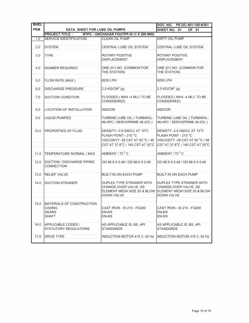
BHEL DOC. NO. PE-DC-401-100-N301PEM DATA SHEET FOR LUBE OIL PUMPS SHEET NO. 01 OF 01
PROJECT TITLE : NTPC - UNCHAHAR FGUTPP-IV (1 X 500 MW)1.0 SERVICE IDENTIFICATION CLEAN OIL PUMP DIRTY OIL PUMP
2.0 SYSTEM CENTRAL LUBE OIL SYSTEM CENTRAL LUBE OIL SYSTEM
3.0 TYPE ROTARY POSITIVE DISPLACEMENT
ROTARY POSITIVE DISPLACEMENT
4.0 NUMBER REQUIRED ONE (01) NO. (COMMON FOR THE STATION)
ONE (01) NO. (COMMON FOR THE STATION)
5.0 FLOW RATE (MAX.) 8250 LPH 8250 LPH
6.0 DISCHARGE PRESSURE 2.0 KG/CM2 (g) 2.0 KG/CM2 (g)
7.0 SUCTION CONDITION FLOODED ( MAX -4 MLC TO BE CONSIDERED)
FLOODED ( MAX -4 MLC TO BE CONSIDERED)
8.0 LOCATION OF INSTALLATION INDOOR INDOOR
9.0 LIQUID PUMPED TURBINE LUBE OIL ( TURBINOL- TURBINE LUBE OIL ( TURBINOL-46-HPC / SERVOPRIME 46-IOC ) 46-HPC / SERVOPRIME 46-IOC )
10.0 PROPERTIES OF FLUID DENSITY- 0.9 GM/CC AT 15oC DENSITY- 0.9 GM/CC AT 15oCFLASH POINT - 210 oC FLASH POINT - 210 oCVISCOSITY -28 CST AT 50 oC / 48 VISCOSITY -28 CST AT 50 oC / 48CST AT 37.8oC / 140 CST AT 20oC CST AT 37.8oC / 140 CST AT 20oC
11.0 TEMPERATURE NORMAL / MAX AMBIENT / 70 0 C AMBIENT / 70 0 C
12.0 SUCTION / DISCHARGE PIPING CONNECTION
OD 88.9 X 5.49 / OD 88.9 X 5.49 OD 88.9 X 5.49 / OD 88.9 X 5.49
13.0 RELIEF VALVE BUILT-IN ON EACH PUMP BUILT-IN ON EACH PUMP
14.0 SUCTION STRAINER DUPLEX TYPE STRAINER WITH CHANGE-OVER VALVE, SS ELEMENT MESH SIZE 20 & BLOW DOWN VALVE
DUPLEX TYPE STRAINER WITH CHANGE-OVER VALVE, SS ELEMENT MESH SIZE 20 & BLOW DOWN VALVE
15.0 MATERIALS OF CONSTRUCTION CASING CAST IRON - IS 210 - FG260 CAST IRON - IS 210 - FG260GEARS EN-8/9 EN-8/9SHAFT EN-8/9 EN-8/9
16.0 APPLICABLE CODES / STATUTORY REGULATIONS
AS APPLICABLE IS, BS, API STANDARDS
AS APPLICABLE IS, BS, API STANDARDS
17.0 DRIVE TYPE INDUCTION MOTOR 415 V, 50 Hz INDUCTION MOTOR 415 V, 50 Hz
Page 15 of 70
TITLE SPECIFICATION NO. PE-TS-STD-567-A001
TECHNICAL SPECIFICATION FOR VOLUME II - B
LUBE OIL PUMPS SECTION -D
REV 0 DATE 25.06.2014
SHEET OF
PEM
-666
6-0
TECHNICAL SPECIFICATIONS
FOR
LUBE OIL TRANSFER PUMPS
SECTION – C
(ELECTRICAL PORTION)
BHARAT HEAVY ELECTRICALS LTD POWER SECTOR PROJECT ENGINEERING MANAGEMENT
PPEI, NOIDA-INDIA
Page 16 of 70
TECHNICAL SPECIFICATION FOR
LUBE OIL TRF PUMP (ELECTRICAL PORTION)
SPECIFICATION NO. PE-TS-401-567-A001VOLUME II B SECTION-CREV 01 DATE 25.06.14
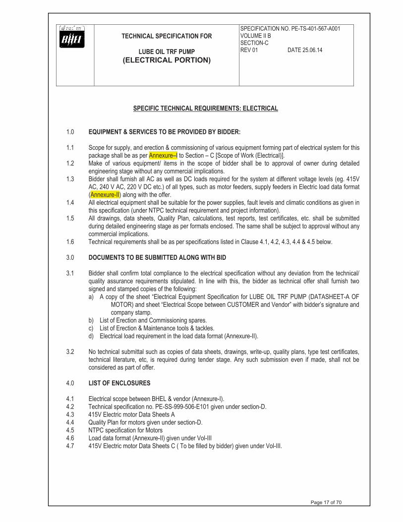
SPECIFIC TECHNICAL REQUIREMENTS: ELECTRICAL
1.0 EQUIPMENT & SERVICES TO BE PROVIDED BY BIDDER:
1.1 Scope for supply, and erection & commissioning of various equipment forming part of electrical system for this package shall be as per Annexure–I to Section – C [Scope of Work (Electrical)].
1.2 Make of various equipment/ items in the scope of bidder shall be to approval of owner during detailed engineering stage without any commercial implications.
1.3 Bidder shall furnish all AC as well as DC loads required for the system at different voltage levels (eg. 415V AC, 240 V AC, 220 V DC etc.) of all types, such as motor feeders, supply feeders in Electric load data format (Annexure-II) along with the offer.
1.4 All electrical equipment shall be suitable for the power supplies, fault levels and climatic conditions as given in this specification (under NTPC technical requirement and project information).
1.5 All drawings, data sheets, Quality Plan, calculations, test reports, test certificates, etc. shall be submitted during detailed engineering stage as per formats enclosed. The same shall be subject to approval without any commercial implications.
1.6 Technical requirements shall be as per specifications listed in Clause 4.1, 4.2, 4.3, 4.4 & 4.5 below.
3.0 DOCUMENTS TO BE SUBMITTED ALONG WITH BID
3.1 Bidder shall confirm total compliance to the electrical specification without any deviation from the technical/ quality assurance requirements stipulated. In line with this, the bidder as technical offer shall furnish two signed and stamped copies of the following: a) A copy of the sheet “Electrical Equipment Specification for LUBE OIL TRF PUMP (DATASHEET-A OF
MOTOR) and sheet “Electrical Scope between CUSTOMER and Vendor” with bidder’s signature and company stamp.
b) List of Erection and Commissioning spares. c) List of Erection & Maintenance tools & tackles.d) Electrical load requirement in the load data format (Annexure-II).
3.2 No technical submittal such as copies of data sheets, drawings, write-up, quality plans, type test certificates, technical literature, etc, is required during tender stage. Any such submission even if made, shall not be considered as part of offer.
4.0 LIST OF ENCLOSURES
4.1 Electrical scope between BHEL & vendor (Annexure-I). 4.2 Technical specification no. PE-SS-999-506-E101 given under section-D. 4.3 415V Electric motor Data Sheets A 4.4 Quality Plan for motors given under section-D. 4.5 NTPC specification for Motors 4.6 Load data format (Annexure-II) given under Vol-III 4.7 415V Electric motor Data Sheets C ( To be filled by bidder) given under Vol-III.
Page 17 of 70

A
NN
EX
UR
E-I
E
LE
CT
RIC
AL
SC
OPE
BE
TW
EE
N C
UST
OM
ER
AN
D V
EN
DO
R
PROJ
ECT:
1X50
0MW
UNC
HAHA
R TP
P
Date:
30.06
.2014
, Rev
-0
PAC
KA
GE
: LU
BE
OIL
PU
MPS
S.N
OD
ET
AIL
SSC
OPE
SUPP
LY
SCO
PE E
&C
R
EM
AR
KS
1 4
15V
SW
ITC
HG
EAR
C
UST
OM
ER
CU
STO
MER
CU
STO
MER
will
pro
vide
onl
y 41
5V su
pply
. Any
oth
er
volta
ge le
vel (
AC
/DC
) req
uire
d w
ill b
e de
rived
by
the
vend
or.
2Lo
cal p
ush
butto
n st
atio
n (S
tart/
Stop
) C
UST
OM
ER
CU
STO
MER
3 Po
wer
cab
les,
ordi
nary
con
trol c
able
s and
scre
ened
con
trol c
able
s be
twee
n eq
uipm
ents
supp
lied
by v
endo
r.
CU
STO
MER
V
endo
r V
endo
r sha
ll fu
rnis
h si
ze a
nd q
uant
ity o
f cab
les r
equi
red
at
cont
ract
stag
e.
4.
Pow
er c
able
s, or
dina
ry c
ontro
l cab
les a
nd sc
reen
ed c
ontro
l cab
les
betw
een
equi
pmen
ts su
pplie
d by
ven
dor &
Cus
tom
er.
CU
STO
MER
C
UST
OM
ER
5 A
ny sp
ecia
l typ
e of
cab
le li
ke c
ompe
nsat
ing.
Co-
axia
l, pr
efab
, M
ICC
and
fibr
e op
tical
Ven
dor
V
endo
r Er
ectio
n m
ater
ials
for s
peci
al c
able
s sha
ll be
in th
e Sc
ope
of b
idde
r. 6
Illum
inat
ion
CU
STO
MER
C
UST
OM
ER7
Cab
ling
mat
eria
l (ca
ble
trays
, acc
esso
ries a
nd c
able
tray
-su
ppor
ting
syst
em, c
ondu
its, M
Box
es/J
Box
es) f
or c
ablin
g be
twee
n eq
uipm
ents
supp
lied
by v
endo
r and
Cus
tom
er.
CU
STO
MER
C
UST
OM
ER
8 Eq
uipm
ent e
arth
ing.
C
UST
OM
ER
CU
STO
MER
BO
Q to
be
furn
ishe
d by
ven
dor a
fter a
war
d of
con
tract
. 9
Mot
ors w
ith B
ase
fram
e an
d fix
ing
hard
war
e fo
r mot
ors.
Ven
dor
CU
STO
MER
M
akes
shal
l be
subj
ect t
o C
UST
OM
ER a
ppro
val a
t con
tract
stag
e.10
a)
Inpu
t cab
le sc
hedu
les
b)C
able
inte
rcon
nect
ion
deta
ils.
c)
Cab
le b
lock
dia
gram
Ven
dor
Ven
dor
Ven
dor
- - -
Cab
le li
stin
g fo
r con
trol c
able
s for
ven
dor-
supp
lied
equi
pmen
t (so
ft co
pies
in th
e cu
stom
er c
able
sche
dule
fo
rmat
) sha
ll be
furn
ishe
d du
ring
deta
il en
gine
erin
g by
ve
ndor
.
11
Equi
pmen
t lay
out d
raw
ings
. V
endo
r -
Layo
ut d
etai
ls b
etw
een
vend
or su
pplie
d eq
uipm
ents
and
in
stal
latio
n dr
awin
gs b
y ve
ndor
12
Cab
le g
land
s and
lugs
for e
quip
men
t sup
plie
d by
ven
dor
Ven
dor
Ven
dor
1. D
oubl
e co
mpr
essi
on N
i-Cr p
late
d br
ass g
land
s. 2.
Sol
der l
ess c
rimpi
ng ty
pe h
eavy
-dut
y tin
ned
copp
er lu
gs
for p
ower
cab
les.
3. H
eavy
dut
y tin
ned
copp
er lu
gs fo
r con
trol c
able
s. 13
A
ny o
ther
item
for c
ompl
eten
ess o
f Sys
tem
V
endo
r C
UST
OM
ER
Supp
ly o
f any
oth
er it
em fo
r com
plet
enes
s of
elec
trica
l wor
k (a
lthou
gh n
ot m
entio
ned
spec
ifica
lly
but r
equi
red
for t
roub
le fr
ee a
nd e
ffic
ient
ope
ratio
n of
th
e sy
stem
) sha
ll be
dee
med
to b
e in
clud
ed in
the
scop
e of
ven
dor w
ithou
t any
ext
ra c
harg
e.
Not
e- A
ll Q
Ps sh
all b
e su
bjec
t to
appr
oval
of C
usto
mer
afte
r aw
ard
of c
ontra
ct.
Pag
e 18
of 7
0

SUB-SECTION – B-09
MOTORS
Page 19 of 70

CLAUSE NO. TECHNICAL REQUIREMENTS
SINGRAULI STPP STAGE-III (1X500 MW)
EPC PACKAGE
TECHNICAL SPECIFICATION SECTION - VI
PART-B
SUB-SECTION-B-09 MOTORS
PAGE 1 OF 9
1.00.00 GENERAL REQUIREMENTS
1.01.00 For the purpose of design of equipment/systems, an ambient temperature of 50 deg. Centigrade and relative humidity of 95% (at 40 deg C) shall be considered. The equipment shall operate in a highly polluted environment.
1.02.00 All equipments shall be suitable for rated frequency of 50 Hz with a variation of +3% & -5%, and 10% combined variation of voltage and frequency unless specifically brought out in the specification.
1.03.00 Contractor shall provide fully compatible electrical system, equipments, accessories and services.
1.04.00 All the equipment, material and systems shall, in general, conform to the latest edition of relevant National and international Codes & Standards, especially the Indian Statutory Regulations.
1.05.00 The auxiliary AC voltage supply arrangement shall have 11kV, 3.3 kV and 415V systems. It shall be designed to limit voltage variations as given below under worst operating condition :
(a) 11kV, 3.3 kV +/- 6%
(b) 415/240V +/- 10%
1.06.00 The voltage level for motors shall be as follows :-
a) Upto 0.2KW : Single phase 240V AC / 3 phase 415V AC
b) Above 0.2KW and upto 200KW : 3 phase 415V AC
c) Above 200KW and upto 1500 KW: 3.3 kV
d) Above 1500 KW : 11 kV
Voltage rating for special purpose motors viz. screw compressors and those with VFD shall be as per manufacturer standard.
For CHP conveyor’s motor above 160KW rating 3.3KV, three phase AC supply is to be used. However all the motors on the Stacker/ Reclaimer machine shall be on 415V AC only.
1.07.00 Fault level shall be limited to 40kA RMS for 1 second for 11kV & 3.3 kV system and 45 kA RMS 1 second for 415V system. 415V system shall be solidly grounded and 220 VDC system shall be isolated type.
1.08.00 Paint shade shall be as per RAL 5012 (Blue) for indoor and outdoor equipment.
Page 20 of 70

CLAUSE NO. TECHNICAL REQUIREMENTS
SINGRAULI STPP STAGE-III (1X500 MW)
EPC PACKAGE
TECHNICAL SPECIFICATION SECTION - VI
PART-B
SUB-SECTION-B-09 MOTORS
PAGE 2 OF 9
1.09.00 The responsibility of coordination with electrical agencies and obtaining all necessary clearances shall be of the contractor.
1.10.00 Degree of Protection
Degree of protection for various enclosures as per IS:4691, IEC60034-05 shall be as follows :-
i) Indoor motors - IP 54
ii) Outdoor motors - IP 55
iii) Cable box-indoor area - IP 54
iv) Cable box-Outdoor area - IP 55
2.00.00 CODES AND STANDARDS
1) Three phase induction motors : IS:325, IEC:60034
2) Single phase AC motors : IS:996, IEC:60034
3) Crane duty motors : IS:3177, IEC:60034
4) DC motors/generators : IS:4722
5) Energy Efficient motors : IS 12615
3.00.00 TYPE
3.01.00 AC Motors:
a) Squirrel cage induction motor suitable for direct-on-line starting.
b) Continuous duty LT motors upto 160 KW Output rating (at 50 deg.C ambient temperature), shall be Energy Efficient motors, Efficiency class-Eff 1, conforming to IS 12615.
c) Crane duty motors shall be slip ring/ squirrel cage Induction motor as per the requirement.
3.02.00 DC Motors Shunt wound.
4.00.00 RATING
(a) Continuously rated (S1). However, crane motors shall be rated for S4 duty, 40% cyclic duration factor.
(b) Whenever the basis for motor ratings are not specified in the corresponding mechanical specification sub-sections, maximum continuous motor ratings
Page 21 of 70

CLAUSE NO. TECHNICAL REQUIREMENTS
SINGRAULI STPP STAGE-III (1X500 MW)
EPC PACKAGE
TECHNICAL SPECIFICATION SECTION - VI
PART-B
SUB-SECTION-B-09 MOTORS
PAGE 3 OF 9
shall be at least 10% above the maximum load demand of the driven equipment under entire operating range including voltage and frequency variations.
(c) For BFP motor the starting MVA shall be restricted to 58 MVA.
5.00.00 TEMPERATURE RISE
Air cooled motors
70 deg. C by resistance method for both thermal class 130(B) & 155(F) insulation.
Water cooled
80 deg. C over inlet cooling water temperature mentioned elsewhere, by resistance method for both thermal class 130(B) & 155(F) insulation.
41 deg.C over inlet cooling water maximum temperature of 39 deg.C for thermal class Y wet wound Boiler circulation pump motor.
6.00.00 OPERATIONAL REQUIREMENTS
6.01.00 Starting Time
6.01.01 For motors with starting time upto 20 secs. at minimum permissible voltage during starting, the locked rotor withstand time under hot condition at highest voltage limit shall be at least 2.5 secs. more than starting time.
6.01.02 For motors with starting time more than 20 secs. and upto 45 secs. at minimum permissible voltage during starting, the locked rotor withstand time under hot condition at highest voltage limit shall be at least 5 secs. more than starting time.
6.01.03 For motors with starting time more than 45 secs. at minimum permissible voltage during starting, the locked rotor withstand time under hot condition at highest voltage limit shall be more than starting time by at least 10% of the starting time.
6.01.04 Speed switches mounted on the motor shaft shall be provided in cases where above requirements are not met.
6.02.00 Torque Requirements
6.02.01 Accelerating torque at any speed with the lowest permissible starting voltage shall be at least 10% motor full load torque.
6.02.02 Pull out torque at rated voltage shall not be less than 205% of full load torque. It shall be 275% for crane duty motors.
Page 22 of 70

CLAUSE NO. TECHNICAL REQUIREMENTS
SINGRAULI STPP STAGE-III (1X500 MW)
EPC PACKAGE
TECHNICAL SPECIFICATION SECTION - VI
PART-B
SUB-SECTION-B-09 MOTORS
PAGE 4 OF 9
6.03.00 Starting voltage requirement
(a) 85% up to 1500KW (except for AOP motor which is 80%)
(b) 80% from 1501 KW to 4000KW
(c) 75% > 4000KW
7.00.00 DESIGN AND CONSTRUCTIONAL FEATURES
7.01.00 Suitable single phase space heaters shall be provided on motors rated 30KW and above to maintain windings in dry condition when motor is standstill. Separate terminal box for space heaters & RTDs shall be provided. However for flame proof motors , space heater terminals inside the main terminal box may be acceptable.
7.02.00 All motors shall be either Totally enclosed fan cooled (TEFC) or totally enclosed tube ventilated (TETV) or Closed air circuit air cooled (CACA) type. However, motors rated 3000KW or above can be Closed air circuit water cooled (CACW). CW motors can be screen protected drip proof (SPDP) type. Motors located in hazardous areas shall have flame proof enclosures conforming to IS:2148 as detailed below
(a) Fuel oil area : Group – IIB
(b) Hydrogen generation : Group - IIC (or Group-I, Div-II as per NEC) plant area
7.03.00 Winding and Insulation
(a) Type : Non-hygroscopic, oil resistant, flame resistant
(b) Starting duty : Two hot starts in succession, with motor initially at normal running temperature. However the conveyor motor shall be suitable for 3 consecutive hot starts.
(c) 11kV & 3.3 kV AC motors
:Thermal class 155 (F) insulation. The winding insulation process shall be total Vacuum Presure Impregnated i.e resin poor method. The lightning Impulse & interturn insulation surge withstand level shall be as per IEC-60034 part-15
(d) 240VAC, 415V AC & 220V DC motors
: Thermal Class( B ) or better
7.04.00 Motors rated above 1000KW shall have insulated bearings to prevent flow of shaft currents.
Page 23 of 70

CLAUSE NO. TECHNICAL REQUIREMENTS
SINGRAULI STPP STAGE-III (1X500 MW)
EPC PACKAGE
TECHNICAL SPECIFICATION SECTION - VI
PART-B
SUB-SECTION-B-09 MOTORS
PAGE 5 OF 9
7.05.00 Motors with heat exchangers shall have dial type thermometer with adjustable alarm contacts to indicate inlet and outlet primary air temperature.
7.06.00 Noise level for all the motors shall be limited to 85dB(A) except for BFP motor for which the maximum limit shall be 90dB(A). Vibration shall be limited within the limits prescribed in IS:12075 / IEC 60034-14 . Motors shall withstand vibrations produced by driven equipment. HT motor bearing housings shall have flat surfaces, in both X and Y directions, suitable for mounting 80mmX80mm vibration pads.
7.07.00 In HT motors, at least four numbers simplex / two numbers duplex platinum resistance type temperature detectors shall be provided in each phase stator winding. Each bearing of HT motor shall be provided with dial type thermometer with adjustable alarm contact and preferably 2 numbers duplex platinum resistance type temperature detectors.
7.08.00 Motor body shall have two earthing points on opposite sides.
7.09.00 HT motors can be offered with either elastimould termination or dust tight phase separated double walled (metallic as well as insulated barrier) cable boxes. In case elastimould terminations are offered, then protective cover and trifurcating sleeves shall also be provided. In case cable box is offered, then Employer shall provide termination kit. Removable gland plates of thickness 3 mm (hot/cold rolled sheet steel) or 4 mm (non magnetic material for single core cables) shall be provided in case of cable boxes.
7.10.00 The spacing between gland plate & centre of terminal stud shall be as per Table-I.
7.11.00 All motors shall be so designed that maximum inrush currents and locked rotor and pullout torque developed by them at extreme voltage and frequency variations do not endanger the motor and driven equipment.
7.12.00 The motors shall be suitable for bus transfer schemes provided on the 11kV, 3.3 kV /415V systems without any injurious effect on its life.
7.13.00 For motors rated 2000 KW & above, neutral current transformers of PS class shall be provided on each phase in a separate neutral terminal box.
7.14.00 11kV and 3.3 kV motor Terminal Box shall be suitable for fault level of 750MVA for 0.12 sec and 250 MVA for 0.12 sec respectively. Elastimould termination kit shall be suitable for fault level of 25 KA for 0.17 seconds.
7.15.00 The size and number of cables (for HT and LT motors) to be intimated to the successful bidder during detailed engineering and the contractor shall provide terminal box suitable for the same.
8.00.00 The ratio of locked rotor KVA at rated voltage to rated KW shall not exceed the following (without any further tolerance) except for BFP Motor.
Page 24 of 70

CLAUSE NO. TECHNICAL REQUIREMENTS
SINGRAULI STPP STAGE-III (1X500 MW)
EPC PACKAGE
TECHNICAL SPECIFICATION SECTION - VI
PART-B
SUB-SECTION-B-09 MOTORS
PAGE 6 OF 9
(a) Upto 110KW : 11.0 (For AOP motor it shall be 8.0)
(b) Above 110KW & upto 1500KW : 10.0
(c) Above 1500KW & upto 4000KW : 9.0
(d) Above 4000KW : 6 to 6.5
9.00.00 CW Motor shall be desigined with minimum power factor of 0.8 at design point.
10.00.00 TYPE TEST
10.01.00 HT MOTORS
10.01.01 The contractor shall carry out the type tests as listed in this specification on the equipment to be supplied under this contract. The bidder shall indicate the charges for each of these type tests separately in the relevant schedule of Section - VII- (BPS) and the same shall be considered for the evaluation of the bids. The type tests charges shall be paid only for the test(s) actually conducted successfully under this contract and upon certification by the employer’s engineer.
10.01.02 The type tests shall be carried out in presence of the employer’s representative, for which minimum 15 days notice shall be given by the contractor. The contractor shall obtain the employer’s approval for the type test procedure before conducting the type test. The type test procedure shall clearly specify the test set–up, instruments to be used, procedure, acceptance norms, recording of different parameters, interval of recording, precautions to be taken etc. for the type test(s) to be carried out.
10.01.03 In case the contractor has conducted such specified type test(s) within last ten years as on the date of bid opening, he may submit during detailed engineering the type test reports to the owner for waival of conductance of such test(s). These reports should be for the tests conducted on the equipment similar to those proposed to be supplied under this contract and test(s) should have been either conducted at an independent laboratory or should have been witnessed by a client. The owner reserves the right to waive conducting of any or all the specified type test(s) under this contract. In case type tests are waived, the type test charges shall not be payable to the contractor.
10.01.04 Further the Contractor shall only submit the reports of the type tests as listed in "LIST OF TESTS FOR WHICH REPORTS HAVE TO BE SUBMITTED"and carried out within last ten years from the date of bid opening. These reports should be for the test conducted on the equipment similar to those proposed to be supplied under this contract and the test(s) should have been either conducted at an independent laboratory or should have been witnessed by a client. However if the contractor is not able to submit report of the type test(s) conducted within last ten years from the date of bid opening, or in the case of type test report(s) are not found to be meeting the specification requirements, the contractor shall conduct all such tests under this
Page 25 of 70

CLAUSE NO. TECHNICAL REQUIREMENTS
SINGRAULI STPP STAGE-III (1X500 MW)
EPC PACKAGE
TECHNICAL SPECIFICATION SECTION - VI
PART-B
SUB-SECTION-B-09 MOTORS
PAGE 7 OF 9
contract at no additional cost to the owner either at third party lab or in presence of client/owners representative and submit the reports for approval.
10.01.05 LIST OF TYPE TESTS TO BE CONDUCTED
The following type tests shall be conducted on each type and rating of HT motor
(a) No load saturation and loss curves upto approximately 115% of rated voltage
(b) Measurement of noise at no load.
(c) Momentary excess torque test (subject to test bed constraint).
(d) Full load test(subject to test bed constraint)
(e) Temperature rise test at rated conditions. During heat run test, bearing temp., winding temp., coolant flow and its temp. shall also be measured. In case the temperature rise test is carried at load other than rated load, specific approval for the test method and procedure is required to be obtained. Wherever ETD's are provided, the temperature shall be measured by ETD's also for the record purpose.
(f) Lightning Impulse withstand test on the sample coil shall be as per IEC-60034, part-15
(g) Surge-withstand test on interturn insulation shall be as per clause no. 5.1.2 of IEC 60034, part-15
10.01.06 LIST OF TESTS FOR WHICH REPORTS HAVE TO BE SUBMITTED
The following type test reports shall be submitted for each type and rating of HT motor
(a) Degree of protection test for the enclosure followed by IR, HV and no load run test.
(b) Terminal box-fault level withstand test for each type of terminal box of HT motors only.
10.02.00 LT Motors
10.02.01 LT Motors supplied shall be of type tested design. During detailed engineering, the contractor shall submit for Owner's approval the reports of all the type tests as listed in this specification and carried out within last ten years from the date of bid opening.
Page 26 of 70

CLAUSE NO. TECHNICAL REQUIREMENTS
SINGRAULI STPP STAGE-III (1X500 MW)
EPC PACKAGE
TECHNICAL SPECIFICATION SECTION - VI
PART-B
SUB-SECTION-B-09 MOTORS
PAGE 8 OF 9
These reports should be for the test conducted on the equipment similar to those proposed to be supplied under this contract and the test(s) should have been either conducted at an independent laboratory or should have been witnessed by a client.
10.02.02 However if the contractor is not able to submit report of the type test(s) conducted within last ten years from the date of bid opening, or in the case of type test report(s) are not found to be meeting the specification requirements, the contractor shall conduct all such tests under this contract at no additional cost to the owner either at third party lab or in presence of client/owners representative and submit the reports for approval.
10.02.03 LIST OF TESTS FOR WHICH REPORTS HAVE TO BE SUBMITTED
The following type test reports shall be submitted for each type and rating of LT motor of above 50 KW only
1. Measurement of resistance of windings of stator and wound rotor.
2. No load test at rated voltage to determine input current power and speed
3. Open circuit voltage ratio of wound rotor motors ( in case of Slip ring motors)
4. Full load test to determine efficiency power factor and slip .
5. Temperature rise test .
6. Momentary excess torque test.
7. High voltage test .
8. Test for vibration severity of motor.
9. Test for noise levels of motor(Shall be limited as per clause no 7.06.00 of this section)
10. Test for degree of protection and
11. Overspeed test.
10.03.00 All acceptance and routine tests as per the specification and relevant standards shall be carried out. Charges for these shall be deemed to be included in the equipment price.
10.04.00 The type test reports once approved for any projects shall be treated as reference. For subsequent projects of NTPC, an endorsement sheet will be furnished by the manufacturer confirming similarity and “No design Change”. Minor changes if any shall be highlighted on the endorsement sheet.
Page 27 of 70
CLAUSE NO. TECHNICAL REQUIREMENTS
SINGRAULI STPP STAGE-III (1X500 MW)
EPC PACKAGE
TECHNICAL SPECIFICATION SECTION - VI
PART-B
SUB-SECTION-B-09 MOTORS
PAGE 9 OF 9
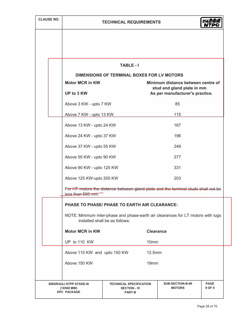
TABLE - I
DIMENSIONS OF TERMINAL BOXES FOR LV MOTORS
Motor MCR in KW Minimum distance between centre of stud and gland plate in mm UP to 3 KW As per manufacturer's practice.
Above 3 KW - upto 7 KW 85
Above 7 KW - upto 13 KW 115
Above 13 KW - upto 24 KW 167
Above 24 KW - upto 37 KW 196
Above 37 KW - upto 55 KW 249
Above 55 KW - upto 90 KW 277
Above 90 KW - upto 125 KW 331
Above 125 KW-upto 200 KW 203
For HT motors the distance between gland plate and the terminal studs shall not be less than 500 mm.
PHASE TO PHASE/ PHASE TO EARTH AIR CLEARANCE:
NOTE: Minimum inter-phase and phase-earth air clearances for LT motors with lugs installed shall be as follows:
Motor MCR in KW Clearance
UP to 110 KW 10mm
Above 110 KW and upto 150 KW 12.5mm Above 150 KW 19mm
Page 28 of 70

ELECTRICAL EQUIPMENT SPECIFICATION FOR FOR LUBE OIL TRF PUMP
SL.NO. PARAMETERS UNIT UNCHAHAR
MOTOR
1 DESIGN AMBIENT TEMP DEG. C 50
2 VOLTAGE SUPPLY AND VARIATION VOLT 415V, + 10%
3FREQUENCY WITH VARIATION
Hz50(+ 3% to - 5%)
4COMBINED VOLTAGE & FREQUENCY VARIATION
10% (absolute)
5MAX ACCEPTABLE RATING OF MOTOR AT 415 V KW
(Upto) 200 KW
6SYSTEM FAULT LEVEL AND ITS DUARTION KA
45kA for 1sec
7SUTABILITY OF TERMINAL BOX FOR FAULT LEVEL AND DURATION
45 KA, 0.2 sec
8CLASS OF INSULATION & TEMP RISE LIMITED TO
THERMAL CLASS 130 B & 155 F INSULATION, TEMP REISE LIMITED TO CLASS B
9MIN. STARTING VOLTAGE 85% up to 1500kW
10 MOTOR RATING FOR SINGLE PHASE SUPPLY
0.2 kW & Below
11 RATIO OF LOCKED ROTOR KVA at rared voltage to RATED KW
11 for BELOW 110kW & 10 for 110 kW to 1500kW
12ACCEPTABLE NOISE LEVEL DB 85dB(A)
13TYPE OF STARTER PROVIDED IN MCC
DOL
14DOP OF ENCLOSURE IP-55 & IP-54 for outdoor &
indoor resp as per IS 4691 & IEC 60034-05.
15SPACE HEATER REQUIREMENT
>30kW30KW & ABOVE
16PAINT SHADE RAL - 5012 (blue)
17
SPECIAL REQUIREMENT TYPE TEST REPORTS MORE THAN 10 YEARS OLD FROM THE DATE OF BID OPENING ARE NOT ACCEPTABLE
DATA SHEET-A( ELECTRICAL PORTION)
Page 29 of 70

TITLE SPECIFICATION NO. PE-TS-STD-567-A001
TECHNICAL SPECIFICATION FOR VOLUME II - B
LUBE OIL PUMPS SECTION -D
REV 0 DATE 25.06.2014
SHEET OF
PEM
-666
6-0
TECHNICAL SPECIFICATIONS
FOR
LUBE OIL TRANSFER PUMPS
SECTION – D
(GENERAL TECHNICAL SPECIFICATION)
BHARAT HEAVY ELECTRICALS LTD POWER SECTOR PROJECT ENGINEERING MANAGEMENT
PPEI, NOIDA-INDIA
Page 30 of 70

TITLE SPECIFICATION NO. PE-TS-STD-567-A001
TECHNICAL SPECIFICATION VOLUME II B
(GENERAL) FOR SECTION D
LUBE OIL PUMPS REV 01 DATE 25.06.2014
SHEET 1 OF 9
PEM
-666
6-0
��1.0� GENERAL��� This�specification�covers�the�design�material�constructional�features�manufacture�assembly�inspection�
&�testing�at�manufacturer's�or�his�subcontractor's�works,�suitable�painting�&�packing�requirements�of�Lube�Oil�transfer�pumps�and�drives�along�with�all�accessories�as�specified�hereinafter.�
��2.0� CODES�&�STANDARDS��� All� equipment,� systems� and� works� covered� under� this� specification� shall� comply� with� all� currently�
applicable�statutory�regulations�and�safety�codes�in�the�locality�where�they�will�be�installed.�They�shall�comply�with�the�latest�editions�of�the�codes�and�standards�as�given�below.�
�a) American�National�Standards�Institute��(ANSI)�
�b) American�Society�of�Testing�&�Materials�(ASTM)�
�c) American�society�of�Mechanical�Engineers�(ASME)�
�d) Hydraulic�Institute�Standards�(HIS)�
�e) American�Petroleum�Institute�(API)�
�f) American�Gear�Manufacturer's�Association�(AGMA)�
�g) National�Electrical�Manufacturer's�Association�(NEMA)�
�h) National�Fire�Protection�Association�(NFPA)�
�i) Indian�Standards�Institute�(ISI)�
�� Other� International/National�standards�such�as�DIN,�VDI,�BS,�IS�etc.�shall�also�be�accepted�subject�to�
the�owner's�approval�for�which�the�bidder�shall�furnish�along�with�the�offer�adequate�information�to�justify�that�these�standards�are�equivalent�or�superior�to�the�standards�mentioned�above.�In�all�such�cases�the�Bidder�shall�furnish�specifically�the�variations�and�deviations�from�the�standards�mentioned�above� together�with� the� complete�word� to�word� translation� of� the� standard� that� are� normally� not�published� in� English� � In� the� event� of� any� conflict� between� the� Codes� and� Standards� and� their�requirements�of�this�specification,�the�requirement�of�this�specification�shall�govern.�
�� All�equipment�covered�by�this�specification�shall�comply�with�all�applicable�laws�and�regulations�of�the�
Republic�of�India.���� In�case�of�any�change�in�code,�standards�and�regulations�between�the�date�of�purchase�order�and�the�
date� when� vendors� proceeds� with� fabrication� the� purchaser� shall� have� the� option� to� incorporate�changed� requirements� without� additional� commercial� implication.� It� shall� be� the� responsibility� of�vendor�to�advice�purchaser�of�the�resulting�effect.�
�����
Page 31 of 70

TITLE SPECIFICATION NO. PE-TS-STD-567-A001
TECHNICAL SPECIFICATION VOLUME II B
(GENERAL) FOR SECTION D
LUBE OIL PUMPS REV 01 DATE 25.06.2014
SHEET 1 OF 9
PEM
-666
6-0
3.0� DESIGN�REQUIREMENTS�&�CONSTRUCTIONAL�FEATURES��3.1� Casting��� The� pump� shall� be� horizontal,� positive� displacement� type,� designed� for� oil� service� and� suitable� for�
occasional�dry�running.�The�casing�shall�also�have�end�plates/pump�cover�which�close�the�ends�of�the�body�to�form�the�pumping�chamber.�The�casing�shall�house�rotating�assembly.�Gear�type�with�a�drive�shaft.�
�3.2� Rotor��� The�rotor�shall�constitute�of�a�shaft�on�which�either�Gear�are�mounted.�The�rotating�assembly�shall�be�
encased� in� the� casing� and� shall� be� properly� sealed.� �Mechanical� Seal� � could� be�offered� for� sealing�purpose.� The� seal�material� shall� have� low� coefficient� of� friction� and� shall� be� suitable� for� the� fluid�handled.�
�3.3� Bearing�&�Lubrication��� Bearings�of�adequate�design�shall�be�provided�for�taking�the�entire�pump�load�arising�from�all�probable�
conditions�for�continuous�operation�throughout�its�range�of�operation.�The�bearing�shall�be�designed�on�the�basis�of�20,000�working�hours�minimum�for�the�load�corresponding�to�the�duty�point.�Proper�Lubricating�arrangement�for�the�bearing�shall�be�provided.�Bearings�shall�be�easily�accessible�without�disturbing� the�pump�assembly.�The�pump�bearings�shall�be�antifriction�ball/� roller� type�of�adequate�size� to� carry� both� radial� and� axial� loads.� Any� other� type� of� bearing� may� be� accepted� subject� to�acceptance�by�customer.��
�3.4� Coupling��� The� pumps� shall� be� directly� coupled� to� their� drives� through� a� flexible� coupling.� Suitable� coupling�
guards�also�shall�be�provided�along�with�the�coupling.�The�pump�and�its�drive�motor�shall�be�mounted�on�machined�base�frame.�
�3.5� Base�Frame��� Common/individual� base� frame� shall� be� provided� for� pump� and� motor.� The� base� frame� shall� be�
fabricated/casted�construction�providing�rigidity�and�stability�and�shall�be�capable�of�supporting�the�weight�and�reactions�of�the�pump�&�motor.�The�base�plate�will�have�a�drip�pan�with�suitable�draining�arrangement�and�shall�be�suitably�drilled�for�the�anchor�bolts.�The�material�of�construction�shall�be�of�tested�quality�structural�steel�as�per�IS�2062�or�equivalent.��
�Anchor�bolts,�nuts,�lock�nuts,�seating�steel�work�as�required�shall�be�supplied�with�the�equipment.�Only�hexagonal�nuts�shall�be�used�for�holding�down�the�equipment.�
�3.6� Lifting�Arrangement��� Each�pump�shall� incorporate�suitable�lifting�attachments�e.g.� lifting�lugs�or�eye�bolts�etc.�to�facilitate�
erection�&�maintenance.�����
Page 32 of 70

TITLE SPECIFICATION NO. PE-TS-STD-567-A001
TECHNICAL SPECIFICATION VOLUME II B
(GENERAL) FOR SECTION D
LUBE OIL PUMPS REV 01 DATE 25.06.2014
SHEET 1 OF 9
PEM
-666
6-0
3.7� Rating�Plates�&�Name�Plate�� Each�equipment� � � shall� have�permanently�attached� to� it� in� a� conspicuous�position,�a� rating�plate�of�
non�corrosive�material�upon�which�shall�be�engraved�manufacturers�name,�equipment�type�or�serial�number.�
�4.0� OTHER�TECHNICAL�/�DESIGN�&�GENERAL�REQUIREMENTS��4.1� The�data�sheets�for�Pump�and�motors�placed�under�Vol�III�of�specification�forms�part�of�specification.�
The�“*”�marked�details�are�to�be�filled�up�by�the�bidder�without�altering�the�data�already�filled�up.��4.2� The�material�of�construction�of�Strainer�body�will�be�either�ASTM�A�106�Gr.B�pipe�or�ASTM�A216�WCB�
or�fabricated�from�IS�2062�plates.�However,�the�exact�MOC�is�subject�to�acceptance�by�customer�and�there�will�be�no���additional�commercial�implication�on�account�of�above.���
�4.3� The�driving�motor�power�shall�be�selected�based�on�highest�viscosity�of�oil.�The�selection�of�pump�
motor�rating�shall�be�based�on�criterion�given�in�the�electrical�portion�of�the�specification.���4.4� VOID.��4.5� The� pump� shall� be� designed� for� the� normal� operating� temperature� specified� in� the� data� sheet.�
However,� the� pump� should� be� able� to� perform� without� any� malfunctioning� at� the� maximum�temperature�also�as�indicated�in�the�data�sheet.�
�4.6�����VOID.���4.7� �VOID.��4.8� VOID.��4.9� Pumps�shall�be�designed�for�smooth�pulsation�and�noise�free�operation.�Pump�shall�be�designed�to�
have�maximum�efficiency�at�the�normal�duty�point.��4.10� The�design�of�pump�shall�be�so�as�to�minimize�the�end�thrust.���4.11� The�pump�shall�have�minimum�vibration,�noise�and�capacity�reduction�even�when�the�viscosity�of�oil�
increases�during�winter�season.�The�maximum�permissible�noise�level�of�the�pump�set�shall�be�85�dBa�measured�at�a�distance�of�1�metre�horizontal�and�1.5�metre�vertical�from�the�edge�of�pump�motor�set.�
�4.12� Material� of� construction� for� the� vital� parts� shall� be� as� shown� in� data� sheet� or� elsewhere� in� the�
specification.� The� material� of� construction� of� the� other� parts� of� the� pump� shall� be� � � � subject� to�Customer’s�approval�during�detail�engineering�and�any�changes�therein�as�required�by�the�customer�shall�be�provided�by�the�successful�bidder�without�any�commercial�implication.�All�materials�used�for�manufacture�of�the�pump�and�its�components�shall�be�of�tested�quality.�Relevant�test�certificates�shall�be� made� available� to� the� purchaser� before� taking� up� fabrication� work.� In� the� absence� of� such�certificates�the�vendor�shall�arrange�to�carry�out�necessary�tests�required�by�the�code�at�his�cost.��
4.13� The�revision�made�by�successful�bidder�in�any�drawings�and�documents�shall�be�highlighted�by�indicating�the� no.� of� revisions� in� a� triangle� without� fail� so� that� the�minimum� time� is� required� by� customer� � to�review�the�drawings�and�documents.�
�Page 33 of 70

TITLE SPECIFICATION NO. PE-TS-STD-567-A001
TECHNICAL SPECIFICATION VOLUME II B
(GENERAL) FOR SECTION D
LUBE OIL PUMPS REV 01 DATE 25.06.2014
SHEET 1 OF 9
PEM
-666
6-0
4.14� If� required� by� the� customer� during� detail� engineering,� the� successful� bidder� will� submit� � � � � separate�drawing� of� various� assembly� /� sub� �� assembly� � � in� addition� to� GA� drawing� without� any� commercial�implication�to�the�customer.���� � � � � � � � � �
4.15� The�recommended�civil�foundation�drawing�to�be�furnished�by�the�bidder�during�detail�engineering�shall�include�the�followings:���
�a)� Scope�of�work�by�BHEL� and� vendor� shall� be� indicated�with�different� legend�or� in� the� form�of�
note.��b)� Weight�of�moving�parts,�its�frequency�and�its�height�from�floor�shall�be�furnished.� �� � �c)� Recommended� location�of�cable� trench� for� feeding�cable� to�machine�along�with� the�details�of�
cable�entry.� � � � � ��d)� Civil�loads�per�bolt�/�pocket�(static�and�dynamic)�in�tabular�form�considering�worst�case.� ��
�4.16� �The� successful� bidder� will� have� to� depute� competent� designer� (s)� at� BHEL’s� office� during� detailed�
engineering� stage� to�discuss�drawings�and�other� technical�documents�as�and�when� required�by�BHEL.�However,�the�vendor�will�be�informed�in�advance�by�minimum�7�days.����
�4.17� � � �All� the�drawings� � � required�to�be�furnished�to�customer�during�detailed�engineering�stage�shall� include�
technical� parameters,� details� of� paints� and� lubrication,� hardness� and� BOQ� /� BOM� in� tabular� form�indicating�all�major�components�including�bought�out�items�and�their�quantity,�material�of�construction�indicating�its�applicable�code�/�standard,�weight,�make�etc.���
�4.18� All� the� � drawings� and� documents� including� general� arrangement� drawing,� data� sheet,� calculation� etc.�
shall� � be� furnished� to� the� customer� � during� detailed� engineering� stage� and� � include� /� indicate� the�following�details� for� clarity�w.r.t.� Inspection,� construction,� erection� and�maintenance�and� information�etc.:��
�a)� All� drawings� and� documents� shall� bear� BHEL’s� title� block� and� drawing� /� document� number.�
However,� BHEL’s� drawing� /� document�numbering� scheme� shall� be� furnished� to� the� successful�bidder�after�the�placement�of�L.O.I.�
�b)� All� drawings� and� documents� shall� indicate� the� list� of� all� reference� drawings� including� general�
arrangement.��c)� All�drawings�shall� include�/�show�plan,�elevation,�side�view,�cross���section,�skin�section,�blow���
up�view�of��all�major�self�manufactured�and�bought�out�items�shall�be�labelled�and�included�in�BOQ�/�BOM�in�tabular�form.�
�d)� Specification� of� painting� shall� be� made� as� a� part� of� general� arrangement� drawing� of� each�
equipment�/�items�indicating�at�least�3�trade�name.��e) Technical�parameters�of�the�equipment��(capacity,�pressure,�fluid���handled,�vibration�limit,�noise�
level�at�a�distance�of�1.0�meter�at�a�level�of�1.5�meters�above�ground,�details�of�coupling,�details�of�motor,�details�of�gears�of�pump,�recommended�capacity�of�hoist,�weight�of�heaviest�(single)�part�/�component�of�the�equipment�and�total�weight���etc.)��in�general�arrangement�drawing�and�these�shall�be�indicated�in�the�drawing�with�dimensions�to�the�extent�possible.�
�
Page 34 of 70

TITLE SPECIFICATION NO. PE-TS-STD-567-A001
TECHNICAL SPECIFICATION VOLUME II B
(GENERAL) FOR SECTION D
LUBE OIL PUMPS REV 01 DATE 25.06.2014
SHEET 1 OF 9
PEM
-666
6-0
f) The� supplier's�drawings�and�data� shall� set� forth�overall� and�detailed�dimensions;� location�and�centre�lines;�pipe�conduit�and�other�connections�schematic�and�wiring�diagrams;��clearance�and�load� points;� space� required� for� withdrawal� or� removal� of� equipment� or� parts� and� such�information�as�will�be�needed�by�Owner�in�order�to�provide�adequate�space�for�and�connection�to�the�equipment.�
�g)� Details�of�cable�entry�for�pump�shall�be�shown�in�all�the�3�views�(plan,�elevation�and�side�view)�
indicating�dimensions�from�a�reference�point.��4.19� All�calculations�which�are�required��to�be�submitted�shall�be�done�manually�and�necessarily�in�SI�units��
and�the�same�shall�be�furnished���along�with�the�copy�of�authentic�supporting�literature�e.g.�Code,�Hand�book,�National�/�international�Standards�etc.���
��5.0 TESTING�&�INSPECTION�AT�MANUFACTURE'S�WORKS��5.1� VOID��5.2� The� supplier� shall� provide� inspection� to�establish�and�maintain�quality�of�workmanship� in�his�works�
and� that� of� his� subcontractors� to� ensure� the�mechanical� accuracy� of� components,� compliance�with�drawings,� identity� and� acceptability� of� all�materials,� part� and� equipment.� He� shall� conduct� all� tests�required�to�ensure�that�the�equipment�and�material� furnished�shall�conform�to�the�requirements�of�the�applicable�codes.�All�tests�and�test�procedure�proposed�by�the�manufacturer�shall�be�submitted�to�the�purchaser�for�his�prior�approval.�The�purchaser�shall�be�notified�well�in�advance�of�the�fabrication�and�major� shop� test� of� the� equipment� for� the� purpose� of� making� general� inspections� and� for� the�progress� report.� The� purchaser's� representative� shall� be� given� full� access� to� the� shop� in�which� the�equipment�is�being�manufactured�or�tested�and�all�test�records�shall�be�made�available�to�him.�A�final�inspection�will�be�made�by�the�purchaser's�representative�before�the�dispatch�of�the�equipment.�Final�performance� tests� for� the� complete� units� shall� be� carried� out� in� the� presence� of� purchaser's�representative.�
�� All�material�used�for�manufacture�of�the�equipment�covered�under�this�specification�shall�be�of�tested�
quality.� Relevant� test� certificate� shall� be� made� available� to� the� purchaser� before� the� final� shop�inspection.�In�case�the�relevant�correlating�test�certificates�are�not�available,�the�supplier�shall�arrange�to�carry�out�the�necessary�tests�required�by�code�at�his�cost.�
�5.3� Steel�forging�used�in�pumps�shall�be�tested�for�both�physical�properties�and�chemical�composition.���5.4� The�castings�shall�be�sound,�clean�and�free�from�porosity�blowholes,�hard�duration�and�other�harmful�
defect.��� Areas,�which�in�the�opinion�of�the�purchaser�will�create�doubts�about�soundness�to�the�castings,�shall�
be�subjected�to�dye�penetration�test�as�per�ASTM�Specification�A�165�95.��� No� welding� or� repairs� shall� be� carried� out� without� prior� permission� of� the� purchaser.� The� entire�
surface�of�the�castings�shall�be�subjected�to�Dye�penetrant�test�as�per�ASTM�A�165�95.�Evaluation�of�indication�shall�be�as�per�relevant�standard.�
�5.5� Welding� procedure,� equipment,� welders� and� operators� shall� be� qualified,� prior� to� taking� up� any�
welding.�Liquid�penetrant�examination�shall�be�carried�out�on�the�weldments�in�accordance�with�the�requirement�of�ASME�Code.�
Page 35 of 70

TITLE SPECIFICATION NO. PE-TS-STD-567-A001
TECHNICAL SPECIFICATION VOLUME II B
(GENERAL) FOR SECTION D
LUBE OIL PUMPS REV 01 DATE 25.06.2014
SHEET 1 OF 9
PEM
-666
6-0
�� The� welding� procedures� shall� clearly� state� the� type� of� material� thickness� joint� details,� preheat�
temperature� maintained,� post� weld� heat� treatment� given,� welding� current� &� voltage� used� during�qualification� of� welding� procedure.� For� all� pressure� parts� and� high�pressure� weld� joints,� the� latest�applicable�requirement�of�the�code�must�be�complied�with.�All�records�in�line�with�the�above�shall�be�maintained� and� made� available� to� the� purchaser.� The� welding� test� shall� be� carried� out� on� the�following:�
�� i)� Root�pass�of�single�groove�welded�but�joint.��� ii)� Finish�surfaces�of�all�fillet�weld.��� iii)� Before� weld� repair� after� defect� has� been� rouged� out� and� grounded� to� ensure� removal� of�
defect.��� iv)� On�impellers�after�any�heat�treatment.��� v)� Radiography�of�butt�weld�joints�shall�be�carried�out�in�accordance�with�the�relevant�code.��5.6� Heat� treatment� operations� including� stress� relieving� shall� be� performed� in� accordance� with� the�
applicable�codes.�Recording�of�temperature�with�thermocouples�placed�in�direct�contact�with�the�job�for�recording�the�metal�temperature�during�heat�treatment�shall�be�done.�
�5.7� Ultrasonic�examination�of�pump�shaft�above�50�mm�diameter�as�per�the�governing�specifications.� In�
absence�of� these,�ultrasonic� testing�should�conform�to�ASTM�A�388�and�evaluation�of� indications�as�per�relevant�standard.�
�5.8� All� the� impellers� shall� � be� statically� and� � dynamically� balanced� at� the� operating� speed� as� per� the�
requirement�of�ISO�1940�G�6.3.���5.9� Performance�Tests��� Performance� tests� shall� be� conducted� for� each� of� the� pump�with� unit�motor� at� the�manufacturer's�
works� in� the�presence�of� the�purchaser�or�his�authorized�agent� in�accordance�with� relevant� Indian/�equivalent� standards.� At� least� 5� points,� approximately� equally� spaced� on� the� characteristic� curve�including� relief� valve� set� pressure,� rated� flow�&� pressure� � � � shall� be� tested� and� acceptance�will� be�determined�as�per�the�relevant�standard.�These�tests�shall�be�conducted�with�actual�drive�motor�being�furnished.�In�general,�performance�tests�shall�include�the�following�tests.�
�a) Establish�flow�and�pressure��characteristic���b) Establish�flow�and�power�characteristic��c) Establish�flow�and�efficiency�characteristic�
�� Purchaser�or�their�authorized�representative�shall�have�access�to�all�the�tests.�Prior�intimation�shall�be�
given�allowing�adequate�time�for�preparation�of�the�witness�of�the�test.�After�the�performance�testing,�the�observations�noted�and�the�computation�of� results� for� rated�performance�shall�be�submitted�to�purchaser� for� approval.� On� approval� the� pump� shall� be� undertaken� for� strip� testing� and� its�components� shall� be� examined� for� visual� and� other� tests� before� being� taken� for� dispatch� in� the�presence�of�purchaser�or�their�authorized�inspection�agencies.�
Page 36 of 70

TITLE SPECIFICATION NO. PE-TS-STD-567-A001
TECHNICAL SPECIFICATION VOLUME II B
(GENERAL) FOR SECTION D
LUBE OIL PUMPS REV 01 DATE 25.06.2014
SHEET 1 OF 9
PEM
-666
6-0
�� Test� on� each� pump� for� vibration� level� in� the� transverse,� horizontal� and� vertical� directions� shall� be�
carried� out.� Noise� level� shall� be� measured� at� the� rated� speed.� Measurement� of� oil� leakage� at�seal/stuffing�box�shall�be�recorded�if�any.�
�5.10� Test�at�Site��� The�pumps�will�be�tested�at�site�to�verify�its�mechanical�performance�and�checking�the�vibration�and�
noise� level.� If� the� pumps� fail� to� operate� smoothly� then� such� deficiencies� shall� be� rectified� by� the�supplier� by�making� suitable� alterations� in� the� pump� set� and� additional� tests� required� to� show� the�effect�of�such�alterations�shall�be�performed�by�him.�The�change�made�in�the�pump�shall�be�certified�with�technical�back�up�information�to�the�satisfaction�of�the�purchaser.�
�5.11� Performance�Guarantee��� The�vendor�shall�guarantee�the�material�and�workmanship�of�all�equipment�as�well�as�the�operation�of�
the�pump�as�per�requirement�of�this�specification.��� The�vendor�shall�also�guarantee�for�each�pump�the�discharge�pressure�at�the�specified�rated�capacity�
and�also�corresponding�efficiency,�brake�horsepower�and�relief�valve�set�pressure.���6.0� CLEANING�PROTECTION�&�PAINTING��� Before�shipment�of�the�equipment�to�be�supplied�under�this�specification,�internal�surfaces�of�all�parts�
shall�be�cleaned�to�remove�loose�dirt,�weld�rod�stubs�and�other�foreign�objects�prior�to�final�assembly�of�the�equipment.�
�� Liquid�used�for�hydro�testing�or�cleaning�shall�be�drained�from�the�parts.�Excess�oil�and�grease�shall�be�
removed�by�wiping.�All�openings� shall�be�covered� to�guard�against�damage�and�entrance�of� foreign�objects�during�shipment.�Hydraulic�tested�parts�shall�not�be�packed�till�the�inside�surface�becomes�dry.�
�� Particular�care�shall�be�taken�to�ensure�that�all�foundry�sand�and�loose�material�is�properly�removed�
by�feting.��� Ends�shall�be�protected�from�external�damage�and�sealed�against�the�ingress�of�dirt.��� A�thin�short�steel�circular�blanking�plate�of�a�diameter�1/4"�less�than�the�bolt�holes�inner�PCD�shall�be�
firmly�fixed�to�the�flange�faces�by�the�application�of�adhesive�after�first�ensuring�that�the�flange�faces�have� been� thoroughly� degreased.� A� wooden� blank� should� then� be� bolted� to� the� flange� using� a�minimum�of�four�bolts.��
�� All� piping� shall� be� closed�after� shop�assembly�by� shot�blasting�or�other�means� approved�by�owner.�
Lube�oil�piping�or�carbon�steel�piping�shall�be�pickled.��� The�metal�surface�shall�be�painted�with�two�(2)�coats�of�approved�anti�corrosive�primer�paint�as�per�
paint� supplier's� instruction.�All�machined� surface� shall� have� two� (2)� coats�of�water� repellent� grease�after� thorough� cleaning.� All� exposed� surfaces� shall� have� two� (2)� coats� of� approved� finish� paint� in�addition�to�primer�as�per�paint�supplier's�instruction.�
�
Page 37 of 70

TITLE SPECIFICATION NO. PE-TS-STD-567-A001
TECHNICAL SPECIFICATION VOLUME II B
(GENERAL) FOR SECTION D
LUBE OIL PUMPS REV 01 DATE 25.06.2014
SHEET 1 OF 9
PEM
-666
6-0
� All�parts�shall�be�properly�boxed,�crated�or�otherwise�protected�for�transportation.�All�openings�should�be� properly� covered� before� crating/boxing� to� prevent� ingress� of� dirt/dust/moisture� and� other�undesirables.�Spare�parts�shall�be�packed�for�long�storage�without�injury.�
�� For�export�jobs,�seaworthy�packing�shall�be�used.�Details�of�Seaworthy�packing�will�be�either�project�
specific.� In� case� there� is�no� specification� for� seaworthy�packing,� the� same� shall� be� furnished�by� the�bidder�for�BHEL’s�approval.�However,�there�will�not�be�any�additional�cost� implication�on�account�of�the�same.���
�7.0� DRAWINGS/DOCUMENTS� AND� DATA� TO� BE� FURNISHED� BY� VENDOR� AFTER� AWARD� OF� THE�
CONTRACT.��� After�award�of�Contract,�the�vendor�will�give���following�drawings�for�all�the�configurations�for�Pump��
Motor�Set�and�Strainers�leaving�project�specific�details�as�blank�which�can�be�filled�up�depending�upon�project�requirement.��
�� i)�Fully�dimensional�outline�General�Arrangement�drawings�along�with�foundation�details�of�the�pump�
with�motor�assembly�unit.����
ii)� Fully� dimensional� outline� General� Arrangement� and� foundation� arrangement� drawings� of� the�strainer�unit.��
��� iii)�Cross�sectional�drawing�of�the�equipment�showing�the�details�of�assembly�of�components�and�their�
material�of�construction�with�standard�applicable�codes.��
iv)� Characteristic� curves� of� pump� at� minimum,� maximum� and� rated� viscosity� of� oil� showing� the�following:�
�� a)� Flow�Vs.�Pressure���� b)� Flow�Vs.�Power��
c) Flow�Vs.�Efficiency���
v)����Duly�filled�up�data�sheet�of�Pump,�Motor���
vi)���Calculation�for�selection�of�Motor�Rating�
vii)���Pressure�drop�calculation�across�strainer�
viii) Operation�maintenance�manual.�
ix) ��Quality�plans�duly�corrected�in�line�with�customer’s�comments,�if�any.����8.0� MANUFACTURERS�NAME�AND�TAG�PLATES:��� Each�pump�shall� have�a�permanently�attached�brass�metal� tag�on� the�body� indicating� the� following�
information�both�in�Hindi�and�English:��
a)� Manufacturer's�name�and�trade�mark.��� b)� Capacity�and�Pressure.�
Page 38 of 70

TITLE SPECIFICATION NO. PE-TS-STD-567-A001
TECHNICAL SPECIFICATION VOLUME II B
(GENERAL) FOR SECTION D
LUBE OIL PUMPS REV 01 DATE 25.06.2014
SHEET 1 OF 9
PEM
-666
6-0
�� c)� Design�Pressure.��
d) Equipment�tag�no�as�furnished�during�the�contract.��� The�equipment�tag�no�will�be�indicated�by�the�engineer�on�the�drawing�submitted�for�approval�by�the�
vendor.�����
Page 39 of 70

TITLE : GENERAL TECHNICAL REQUIREMENTs
FOR
LV MOTORS
SPECIFICATION NO. PE-SS-999-506-E101VOLUME NO. : II-BSECTION : DREV NO. : 00 DATE :SHEET : 1 OF 1
GENERAL TECHNICAL REQUIREMENTS
FOR
LV MOTORS
SPECIFICATION NO.: PE-SS-999-506-E101 Rev 00
Page 40 of 70

TITLE : GENERAL TECHNICAL REQUIREMENTs
FOR
LV MOTORS
SPECIFICATION NO. PE-SS-999-506-E101VOLUME NO. : II-BSECTION : DREV NO. : 00 DATE : SHEET : 1 OF 4
1.0 INTENT OF SPECIFIATION
The specification covers the design, materials, constructional features, manufacture, inspection and testing at manufacturer’s work, and packing of Low voltage (LV) squirrel cage induction motors along with all accessories for driving auxiliaries in thermal power station.
Motors having a voltage rating of below 1000V are referred to as low voltage (LV) motors.
2.0 CODES AND STANDARDS
Motors shall fully comply with latest edition, including all amendments and revision, of following codes and standards:
IS:325 Three phase Induction motors IS : 900 Code of practice for installation and maintenance of induction motors IS: 996 Single phase small AC and universal motors IS: 4722 Rotating Electrical machines IS: 4691 Degree of Protection provided by enclosures for rotating electrical machines IS: 4728 Terminal marking and direction of rotation of electrical machines IS: 1231 Dimensions of three phase foot mounted induction motors IS: 8789 Values of performance characteristics for three phase induction motors IS: 13555 Guide for selection and application of 3-phase A.C. induction motors for
different types of driven equipment IS: 2148 Flame proof enclosures for electrical appliance IS: 5571 Guide for selection of electrical equipment for hazardous areas IS: 12824 Type of duty and classes of rating assigned IS: 12802 Temperature rise measurement of rotating electrical machnines IS: 12065 Permissible limits of noise level for rotating electrical machines IS: 12075 Mechnical vibration of rotating electrical machines
In case of imported motors, motors as per IEC-34 shall also be acceptable.
3.0 DESIGN REQUIREMENTS
3.1 Motors and accessories shall be designed to operate satisfactorily under conditions specified in electric motor data sheet-A and Project Information, including voltage & frequency variation of supply system as defined in Data sheet-A
3.2 Motors shall be continuously rated at the design ambient temperature specified in elelctric motor Data Sheet-A and other site conditions specified under Project Information. Motor ratings shall have at least a 15% margin over the continuous maximum demand of the driven equipment, under entire operating range including voltage & frequency variation specified above.
3.3 Starting Requirements
3.3.1 Motor characteristics such as speed, starting torque, break away torque and starting time shall be properly co-ordinated with the requirements of driven equipment. The accelerating torque at any speed with the minimum starting voltage shall be at least 10% higher than that of the driven equipment.
3.3.2 Motors shall be capable of starting and accelerating the load with direct on line starting without exceeding acceptable winding temperature.
Page 41 of 70

TITLE : GENERAL TECHNICAL REQUIREMENTs
FOR
LV MOTORS
SPECIFICATION NO. PE-SS-999-506-E101VOLUME NO. : II-BSECTION : DREV NO. : 00 DATE : SHEET : 2 OF 4
The limiting value of voltage at rated frequency under which a motor will successfully start and accelerate to rated speed with load shall be taken to be a constant value as per Data Sheet - A during the starting period of motors.
3.3.3 The following frequency of starts shall apply
i) Two starts in succession with the motor being initially at a temperature not exceeding the rated load temperature.
ii) Three equally spread starts in an hour the motor being initially at a temperature not exceeding the rated load operating temperature. (not to be repeated in the second successive hour)
iii) Motors for coal conveyor and coal crusher application shall be suitable fro three consecutive hot starts followed by one hour interval with maximum twenty starts per day and shall be sutable fro mimimum 20,000 starts during the life time of the motor
3.4 Running Requirements
3.4.1 Motors shall run satisfactorily at a supply voltage of 75% of rated voltage for 5 minutes with full load without injurious heating to the motor.
3.4.2 Motor shall not stall due to voltage dip in the system causing momentary drop in voltage upto 70% of the rated voltage for duration of 2 secs.
3.5 Stress During bus Transfer
3.5.1 Motors shall withstand the voltage, heavy inrush transient current, mechnical and torque stress developed due to the application of 150% of the rated voltage for at least 1 sec. caused due to vector difference between the motor residual voltage and the incoming supply voltage during occasional auto bus transfer.
3.5.2 Motor and driven equipment shafts shall be adequately sized to satisfactorily withstand transient torque under above condition.
3.6 Maximum noise level measured at distance of 1.0 metres from the outline of motor shall not exceed the values specified in IS 12065.
3.7 The max. vibration velocity or double amplitude of motors vibration as measured at motor bearings shall be within the limits specified in IS: 12075.
4.0 CONSTRUCTIONAL FEATURES
4.1 Indoor motors shall conform to degree of protection IP: 54 as per IS: 4691. Outdoor or semi-indoor motors shall conform to degree of protection IP: 55 as per IS: 4691and shall be of weather-proof construction. Outdoor motors shall be installed under a suitable canopy
4.2 Motors upto 160KW shall have Totally Enclosed Fan Cooled (TEFC) enclosures, the method of cooling conforming to IC-0141 or IC-0151 of IS: 6362.
Motors rated above 160 KW shall be Closed Air Circuit Air (CACA) cooled
4.3 Motors shall be designed with cooling fans suitable for both directions of rotation.
Page 42 of 70

TITLE : GENERAL TECHNICAL REQUIREMENTs
FOR
LV MOTORS
SPECIFICATION NO. PE-SS-999-506-E101VOLUME NO. : II-BSECTION : DREV NO. : 00 DATE : SHEET : 3 OF 4
4.4. Motors shall not be provided with any electric or pneumatic operated external fan for cooling the motors.
4.5 Frames shall be designed to avoid collection of moisture and all enclosures shall be provided with facility for drainage at the lowest point.
4.6 In case Class ‘F’ insulation is provided for LV motors, temperature rise shall be limited to the limits applicable to Class ‘B’ insulation. In case of continuous operation at extreme voltage limits the temperature limits specified in table-1 of IS:325 shall not exceed by more than 10�C.
4.7 Terminals and Terminal Boxes
4.7.1 Terminals, terminal leads, terminal boxes, windings tails and associated equipment shall be suitable for connection to a supply system having a short circuit level, specified in the Data Sheet-A.
Unless otherwise stated in Data Sheet-A, motors of rating 110 kW and above will be controlled by circuit breaker and below 110 kW by switch fuse-contactor. The terminal box of motors shall be designed for the fault current mentioned in data sheet “A”.
4.7.2 Unless otherwise specified or approved, phase terminal boxes of horizontal motors shall be positioned on the left hand side of the motor when viewed from the non-driving end.
4.7.3 Connections shall be such that when the supply leads R, Y & B are connected to motor terminals A B & C or U, V & W respectively, motor shall rotate in an anticlockwise direction when viewed from the non-driving end. Where such motors require clockwise rotation, the supply leads R, Y, B will be connected to motor terminals A, C, B or V W & V respectively.
4.7.4 Permanently attached diagram and instruction plate made preferably of stainless steel shall be mounted inside terminal box cover giving the connection diagram for the desired direction of rotation and reverse rotation.
4.7.5 Motor terminals and terminal leads shall be fully insulated with no bar live parts. Adequate space shall be available inside the terminal box so that no difficulty is encountered for terminating the cable specified in Data Sheet-A.
4.7.6 Degree of protection for terminal boxes shall be IP 55 as per IS 4691.
4.7.7 Separate terminal boxes shall be provided for space heaters.. If this is not possible in case of LV motors, the space heater terminals shall be adequately segregated from the main terminals in the main terminal box. Detachable gland plates with double compression brass glands shall be provided in terminal boxes.
4.7.8. Phase terminal boxes shall be suitable for 360 degree of rotation in steps of 90 degree for LV motors.
4.7.9 Cable glands and cable lugs as per cable sizes specified in Data Sheet-A shall be included. Cable lugs shall be of tinned Copper, crimping type.
4.8 Two separate earthing terminals suitable for connecting G.I. or MS strip grounding conductor of size given in Data Sheet-A shall be provided on opposite sides of motor frame. Each terminal box shall have a grounding terminal.
4.9 General Page 43 of 70

TITLE : GENERAL TECHNICAL REQUIREMENTs
FOR
LV MOTORS
SPECIFICATION NO. PE-SS-999-506-E101VOLUME NO. : II-BSECTION : DREV NO. : 00 DATE : SHEET : 4 OF 4
4.9.1 Motors provided for similar drives shall be interchangeable.
4.9.2 Suitable foundation bolts are to be supplied alongwith the motors.
4.9.3 Motors shall be provided with eye bolts, or other means to facilitate safe lifting if the weight is 20Kgs. and above.
4.9.4 Necessary fitments and accessories shall be provided on motors in accordance with the latest Indian Electricity rules 1956.
4.9.5 All motors rated above 30 kW shall be provided with space heaters to maintain the motor internal air temperature above the dew point. Unless otherwise specified, space heaters shall be suitable for a supply of 240V AC, single phase, 50 Hz.
4.9.6 Name plate with all particulars as per IS: 325 shall be provided
4.9.7 The paint shall be epoxy based and shall be suitable for withstanding specified site conditions.
5.0 INSPECTION AND TESTING
5.1 All materials, components and equipments covered under this specification shall be procured, manufactured, as per the BHEL standard quality plan No. PED-506-00-Q-006/0 enclosed with this specification.
5.2 LV motors of type-tested design shall be provided. In the absence of these, type tests shall have to be conducted by manufacturer without any commercial implication to purchaser.
5.3 All motors shall be subjected to routine tests as per IS: 325 and as per BHEL standard quality plan.
5.4 Motors shall also be subjected to additional tests, if any, as mentioned in Data Sheet A.
6.0 DRAWINGS TO BE SUBMITTED AFTER AWARD OF CONTRACT
a) OGA drawing showing the position of terminal boxes, earthing connections etc. b) Arrangement drawing of terminal boxes. c) Characteristic curves: (To be given for motor above 55 kW unless otherwise specified in Data Sheet).
i) Current vs. time at rated voltage and minimum starting voltage. ii) Speed vs. time at rated voltage and minimum starting voltage.
iii) Torque vs. speed at rated voltage and minimum voltage. For the motors with solid coupling the above curves i), ii), iii) to be furnished for the motors coupled with driven equipment. In case motor is coupled with mechanical equipment by fluid coupling, the above curves shall be furnished with and without coupling.
iv) Thermal withstand curve under hot and cold conditions at rated voltage and max. permissible voltage.
Page 44 of 70

TECHNICAL SPECIFICATIONS
FOR
LUBE OIL TRANSFER PUMPS
QUALITY PLANS
BHARAT HEAVY ELECTRICALS LTD POWER SECTOR PROJECT ENGINEERING MANAGEMENT
PPEI, NOIDA-INDIA
Page 45 of 70

M
AN
UFA
CT
UR
ER
’S N
AM
E &
A
DD
RE
SS
STA
ND
AR
D Q
UA
LIT
Y P
LA
N
PRO
JEC
T
BH
EL
APP
RO
VE
D V
EN
DO
R
ITE
M :
LU
BE
OIL
PU
MPS
SU
B-S
YST
EM
: CL
EA
N/ D
IRT
Y/
RE
TU
RN
OIL
PU
MPS
QP
NO
.
DA
TE
RE
V.
PA
GE
PE:Q
P:
STD
:567
:A00
1 07
/07/
0700 1
of 4
PAC
KA
GE
CO
NT
RA
CT
NO
PO
NO
. C
ON
TR
AC
TO
R
LU
BE
OIL
PU
MPS
B
HA
RA
T H
EA
VY
EL
EC
TR
ICA
LS
L
TD
.SR
. N
O.
CO
MPO
NE
NT
&
OPE
RA
TIO
NS
CH
AR
AC
TE
RIS
TIC
S C
LA
SS
TY
PE O
F C
HE
CK
Q
UA
NT
UM
O
FC
HE
CK
RE
FER
EN
CE
D
OC
UM
EN
T
AC
CE
PTA
NC
E
NO
RM
S FO
RM
AT
OF
RE
CO
RD
A
GE
NC
Y**
10
R
EM
AR
KS
1 2
3 4
5 6
7 8
9
D*
MC
N
11
L
EG
EN
D :
FOR
C
UST
/CO
NSU
L
USE
DO
C.N
O.:
MA
NU
FAC
TU
RE
R /
CO
NT
RA
CT
OR
*
RE
CO
RD
S ID
EN
TIF
IED
WIT
H “
D”
SHA
LL
BE
ESS
ENT
IAL
LY
IN
CL
UD
ED
BY
CO
NT
RA
CT
OR
IN
QA
D
OC
UM
EN
TA
TIO
N
SU
BC
ON
TR
AC
TO
R
** M
: MA
NU
FAC
TU
RE
R/S
UB
CO
NT
RA
CT
OR
,C: C
ON
TR
AC
TO
R /N
OM
INA
TE
D IN
SPE
CT
ION
A
GE
NC
Y ,N
: CU
STO
ME
R/ C
ON
SUL
TA
NT
IN
DIC
AT
E ‘P
’-PE
RFO
RM
, ’W
’-W
ITN
ESS
AN
D ,‘
V’-
VE
RIF
ICA
TIO
N A
S A
PPR
OPR
IAT
E, ’
CH
P’ S
HA
LL
BE
ID
EN
TIF
IED
IN C
OL
UM
N “
RE
MA
RK
S” B
Y C
UST
OM
ER
/ CO
NSU
LT
AN
T
SIG
NA
TU
RE
R
EV
IEW
ED
BY
N
AM
E &
SIG
N O
F A
PPR
OV
ING
AU
TH
OR
ITY
D:\P
RO
JEC
TS\C
ON
TRA
CTS
\401
- Unc
haha
r-B
TG\L
OP\
Tech
. Spe
c\14
QA
P LO
P p.
doc
1.0�
�RA
W�M
ATER
IALS�&�
BOUGHT
�OUTS�CONTR
OL�
�
1.1�
PUMP�CA
SING
(Pum
p�Bo
dy)�
Physical�Prope
rties
�Major
Physical�Test
1/Cast
Appd
�Drg.�
/Data�sheet���Ap
pd�Drg.�
/Data�sheet�
Lab�Re
ports
D*P
VV
��
Chem
ical�Prope
rties�
Major
Chem
ical��Test
1/Cast
�do��
�do�
Lab�Re
port
D*P
VV
1.2�
END�CO
VERS
Physical�Prope
rties
���Major
Physical�Test
1/Cast
�do���
�do��
Lab�Re
ports
D*P
VV
��
Chem
ical�Prope
rties�
Major�
Chem
ical�Test
1/Cast
�do���
�do��
Lab�Re
ports
D*P
VV
1.3�
SHAF
TS�
Physical�Prope
rties
��Major
Physical�Test
1/�Bar
�do���
�do��
Lab�Re
ports
D*P
VV
��
Chem
ical�Prope
rties�
Major
Chem
ical�Test
1/Ba
r�d
o���
�do��
Lab�Re
ports
D*P
VV
��
Sub�surface�de
fects
Major
UT
100%
ASTM
�A�388
100%
�back�
wall�echo�
Fall�in�back�
wall�echo�20
%�
Max.�D
efect�
Echo
��20%
�Max�of�B
.W.E.
Inspectio
n�Re
port�
D*P
VV
�����������������������������������������
�Hardn
ess�
Major
Hardne
ss10
0%Ap
pd�Drg/�
Datasheet�
Appd
�Drg/�
Datasheet�
Lab�Rp
rt.
D*P
VV
1.4�
GEAR
S��
(DRIVING�AN
D�DR
IVEN
)�Ph
ysical�Prope
rties
�Major
Physical�Test
1/�Bar
Appd
�Drg./�
Datasheet���
Appd
�Drg./�
Datasheet�
Lab�Re
port
D*P
VV
��
Chem
ical�Prope
rties�
Major
Chem
ical�te
st�
1/�Bar
Appd
�Drg./�
Datasheet���
Appd
�Drg./�
Datasheet�
Lab�Re
port
D*P
VV
��
�He
at�Treatmen
t100%
�do��
�do�
HT�Chart
D*P
VV
� ��
Sub�surface�de
fects
Major
UT
100%
ASTM
�A�388
100%
�back�
Fall�in�back�
wall�echo�20
%�In
spectio
n�Re
port�
D*P
VV
Pag
e 46
of 7
0

M
AN
UFA
CT
UR
ER
’S N
AM
E &
A
DD
RE
SS
STA
ND
AR
D Q
UA
LIT
Y P
LA
N
PRO
JEC
T
BH
EL
APP
RO
VE
D V
EN
DO
R
ITE
M :
LU
BE
OIL
PU
MPS
SU
B-S
YST
EM
: CL
EA
N/ D
IRT
Y/
RE
TU
RN
OIL
PU
MPS
QP
NO
.
DA
TE
RE
V.
PA
GE
PE:Q
P:
STD
:567
:A00
1 07
/07/
0700 2
of 4
PAC
KA
GE
CO
NT
RA
CT
NO
PO
NO
. C
ON
TR
AC
TO
R
LU
BE
OIL
PU
MPS
B
HA
RA
T H
EA
VY
EL
EC
TR
ICA
LS
L
TD
.SR
. N
O.
CO
MPO
NE
NT
&
OPE
RA
TIO
NS
CH
AR
AC
TE
RIS
TIC
S C
LA
SS
TY
PE O
F C
HE
CK
Q
UA
NT
UM
O
FC
HE
CK
RE
FER
EN
CE
D
OC
UM
EN
T
AC
CE
PTA
NC
E
NO
RM
S FO
RM
AT
OF
RE
CO
RD
A
GE
NC
Y**
10
R
EM
AR
KS
1 2
3 4
5 6
7 8
9
D*
MC
N
11
L
EG
EN
D :
FOR
C
UST
/CO
NSU
L
USE
DO
C.N
O.:
MA
NU
FAC
TU
RE
R /
CO
NT
RA
CT
OR
*
RE
CO
RD
S ID
EN
TIF
IED
WIT
H “
D”
SHA
LL
BE
ESS
ENT
IAL
LY
IN
CL
UD
ED
BY
CO
NT
RA
CT
OR
IN
QA
D
OC
UM
EN
TA
TIO
N
SU
BC
ON
TR
AC
TO
R
** M
: MA
NU
FAC
TU
RE
R/S
UB
CO
NT
RA
CT
OR
,C: C
ON
TR
AC
TO
R /N
OM
INA
TE
D IN
SPE
CT
ION
A
GE
NC
Y ,N
: CU
STO
ME
R/ C
ON
SUL
TA
NT
IN
DIC
AT
E ‘P
’-PE
RFO
RM
, ’W
’-W
ITN
ESS
AN
D ,‘
V’-
VE
RIF
ICA
TIO
N A
S A
PPR
OPR
IAT
E, ’
CH
P’ S
HA
LL
BE
ID
EN
TIF
IED
IN C
OL
UM
N “
RE
MA
RK
S” B
Y C
UST
OM
ER
/ CO
NSU
LT
AN
T
SIG
NA
TU
RE
R
EV
IEW
ED
BY
N
AM
E &
SIG
N O
F A
PPR
OV
ING
AU
TH
OR
ITY
D:\P
RO
JEC
TS\C
ON
TRA
CTS
\401
- Unc
haha
r-B
TG\L
OP\
Tech
. Spe
c\14
QA
P LO
P p.
doc
� � �
wall�echo�
Max.�D
efect�
Echo
e�20
%�
Max�of�B
.W.E.
��
Hardne
ss�Test�
Major
Hardne
ss100%
Appd
�Dwg/�
Data�sh
eet��
Appd
�Dwg/�
Data�sh
eet�
Lab�Rp
rt.
D*P
VV
1.5�
Relief�V
alve�Bod
yPh
ysical�Prope
rties
�Major
Physical�Test
1/Ba
rAp
pd�
Drg/Da
ta�
sheet�
Appd
�Drg/Da
ta�
sheet�
Lab�Re
ports
D*P
VV
����
Chem
ical�Prope
rties�
Major
Chem
ical�Test
1/Ba
r�do��
�do�
Lab�Re
ports
D*P
VV
1.6�
Flanges�(Co
mpanion
�)Ph
ysical�Prope
rties
�Major
Physical�Test
1/�Heat
�do��
�do�
Lab�Re
ports
D*P
VV
��
Chem
ical�Prope
rties
Major
Chem
ical�Test
1/He
at�do��
�do�
Lab�Re
ports
D*P
VV
1.7�
Bearings,�O
il�Seals,�M
e�chanical�Seals�
Make,�size,�B
earin
g�nu
mbe
r,�fin
ish,�fit�
men
t�
Major
Visual,�Fitm
ent
100%
Manufactur�
ing�Draw
ing�
Manufactur�
ing�draw
ing�
Log�bo
okP
V�
1.8�
Electric�M
otors
Review
�of�R
outin
e�test�certificate�
Major
Review
100%
IS�325/IEC
� –34
�for�e
xport�job
�Ap
pd�
Drg/Da
ta�
sheet�
Routine�test�
repo
rt�
D*P
VV
��
�2.
0 IN�PRO
CESS�CONTR
OL
��2.1�
All�com
pone
nts
1.Workm
anship�&�
Finish�
2.Dimen
sions�
Major
Visual�M
easure�
men
t�100%
Mfg.�D
rawing
Mfg.�D
rawing
Log�bo
okP
V�
2.2�
Pump�Casin
g,�Covers,�
Relief�V
alve�Hou
sing�&�
Leak�tightness�
Critical
Hydrotest�at�2
�x�
maxim
um�allowable�10
0%Da
ta�She
ets�/�
Technical�
No�leakages,�
No�de
for�
Inspectio
n�Re
port.�
D*P
WV
Pag
e 47
of 7
0

M
AN
UFA
CT
UR
ER
’S N
AM
E &
A
DD
RE
SS
STA
ND
AR
D Q
UA
LIT
Y P
LA
N
PRO
JEC
T
BH
EL
APP
RO
VE
D V
EN
DO
R
ITE
M :
LU
BE
OIL
PU
MPS
SU
B-S
YST
EM
: CL
EA
N/ D
IRT
Y/
RE
TU
RN
OIL
PU
MPS
QP
NO
.
DA
TE
RE
V.
PA
GE
PE:Q
P:
STD
:567
:A00
1 07
/07/
0700 3
of 4
PAC
KA
GE
CO
NT
RA
CT
NO
PO
NO
. C
ON
TR
AC
TO
R
LU
BE
OIL
PU
MPS
B
HA
RA
T H
EA
VY
EL
EC
TR
ICA
LS
L
TD
.SR
. N
O.
CO
MPO
NE
NT
&
OPE
RA
TIO
NS
CH
AR
AC
TE
RIS
TIC
S C
LA
SS
TY
PE O
F C
HE
CK
Q
UA
NT
UM
O
FC
HE
CK
RE
FER
EN
CE
D
OC
UM
EN
T
AC
CE
PTA
NC
E
NO
RM
S FO
RM
AT
OF
RE
CO
RD
A
GE
NC
Y**
10
R
EM
AR
KS
1 2
3 4
5 6
7 8
9
D*
MC
N
11
L
EG
EN
D :
FOR
C
UST
/CO
NSU
L
USE
DO
C.N
O.:
MA
NU
FAC
TU
RE
R /
CO
NT
RA
CT
OR
*
RE
CO
RD
S ID
EN
TIF
IED
WIT
H “
D”
SHA
LL
BE
ESS
ENT
IAL
LY
IN
CL
UD
ED
BY
CO
NT
RA
CT
OR
IN
QA
D
OC
UM
EN
TA
TIO
N
SU
BC
ON
TR
AC
TO
R
** M
: MA
NU
FAC
TU
RE
R/S
UB
CO
NT
RA
CT
OR
,C: C
ON
TR
AC
TO
R /N
OM
INA
TE
D IN
SPE
CT
ION
A
GE
NC
Y ,N
: CU
STO
ME
R/ C
ON
SUL
TA
NT
IN
DIC
AT
E ‘P
’-PE
RFO
RM
, ’W
’-W
ITN
ESS
AN
D ,‘
V’-
VE
RIF
ICA
TIO
N A
S A
PPR
OPR
IAT
E, ’
CH
P’ S
HA
LL
BE
ID
EN
TIF
IED
IN C
OL
UM
N “
RE
MA
RK
S” B
Y C
UST
OM
ER
/ CO
NSU
LT
AN
T
SIG
NA
TU
RE
R
EV
IEW
ED
BY
N
AM
E &
SIG
N O
F A
PPR
OV
ING
AU
TH
OR
ITY
D:\P
RO
JEC
TS\C
ON
TRA
CTS
\401
- Unc
haha
r-B
TG\L
OP\
Tech
. Spe
c\14
QA
P LO
P p.
doc
Curin
g�of�Pum
p�Casin
g�Ga
skets�
working�pressure�
for�3
0�mins.�
Specificatio
nsmation
2.3�
Gears/�Screw
s�&�Shaft
Surface�De
fects
CRPT
100%
ASME�E�165
No�surface�
defects�
Inspectio
nRe
port�
D*P
VV
2.4�
Gears/�Screw
s�–Indu
c�tio
n�Ha
rdne
ning�
Hardne
ss�
Major
Hardne
ss�M
eas�
urem
ent�
100%
Appd
�Dwg/�
Data�sh
eet�
Appd
�Dwg/�
Data�sh
eet�
Inspectio
n�Re
port�
D*P
V�V
3.0�
SUB�AS
SEMBLY�/�
ASSEMBLY�CO
NTR
OL�
FINAL�IN
SPEC
TION�AND�
TESTING�
��
3.1�
Rotor�A
ssem
bly
Static,�residual�dy�
namic�balancing�
CRStatic,�dynam
ic�Bal�
ancing�
100%
ISO�194
0�IS)�1
940�G�6.3
Inspectio
n�Re
port�
D*P
VV
3.2�
Pump�Assembly
Completen
ess�
Major
Visual,�M
easure�
men
t�100%
Manufactur�
ing�Draw
ing�
Manufactur�
ing�Draw
ing�
Check�List/�
Card�
D*P
V�V
3.3�
Complete�Pu
mp�with
�Unit�M
otor�
1.Performance�fo
r�H�v/s�Q
,�H�v/s�P,�
H�v/s�P
ump�eff.�
2.Vibration�/�N
oise
3.Re
lief�V
alve�se
t�pressure�
4.Leakage��
5.Temp�rise.�
6.Over�a
ll�dimen
�sio
ns�
7.Orie
ntation�
CR � � � � � � � Major�
� Major�
Performance�Test
� � � � � � Measuremen
t�� Visual�
�
100%
� � � � � � � � � �
Hydraulic�In�
stitu
te�Stand
�ards�of�U
SA.�
Tech�Spe
cn,�
Appd
.�Data�
sheets�
� � Approved
�GA�
Drgs.�
�
Hydraulic�In�
stitu
te�Stand
�ards�of�U
SA.�
Tech�Spe
cn,�
Appd
.�Data�
sheets�
Vibration�Lev�
el�=�50�Mi�
cron
s�,max.�
Noise�Level�=�
85�dB�max.�
Test�Rep
ort
D*P
WW
Pump�to�be�tested
�with
�oil�of�visc
osity
�closest�to�lube
�oil�@�
rated�viscosity
��for�
Pressure,�@
�lowest�
viscosity
�for�capacit y�
,�@�hi ghe
st�visc
osity
�for�p
ower�
� � �
Pag
e 48
of 7
0

M
AN
UFA
CT
UR
ER
’S N
AM
E &
A
DD
RE
SS
STA
ND
AR
D Q
UA
LIT
Y P
LA
N
PRO
JEC
T
BH
EL
APP
RO
VE
D V
EN
DO
R
ITE
M :
LU
BE
OIL
PU
MPS
SU
B-S
YST
EM
: CL
EA
N/ D
IRT
Y/
RE
TU
RN
OIL
PU
MPS
QP
NO
.
DA
TE
RE
V.
PA
GE
PE:Q
P:
STD
:567
:A00
1 07
/07/
0700 4
of 4
PAC
KA
GE
CO
NT
RA
CT
NO
PO
NO
. C
ON
TR
AC
TO
R
LU
BE
OIL
PU
MPS
B
HA
RA
T H
EA
VY
EL
EC
TR
ICA
LS
L
TD
.SR
. N
O.
CO
MPO
NE
NT
&
OPE
RA
TIO
NS
CH
AR
AC
TE
RIS
TIC
S C
LA
SS
TY
PE O
F C
HE
CK
Q
UA
NT
UM
O
FC
HE
CK
RE
FER
EN
CE
D
OC
UM
EN
T
AC
CE
PTA
NC
E
NO
RM
S FO
RM
AT
OF
RE
CO
RD
A
GE
NC
Y**
10
R
EM
AR
KS
1 2
3 4
5 6
7 8
9
D*
MC
N
11
L
EG
EN
D :
FOR
C
UST
/CO
NSU
L
USE
DO
C.N
O.:
MA
NU
FAC
TU
RE
R /
CO
NT
RA
CT
OR
*
RE
CO
RD
S ID
EN
TIF
IED
WIT
H “
D”
SHA
LL
BE
ESS
ENT
IAL
LY
IN
CL
UD
ED
BY
CO
NT
RA
CT
OR
IN
QA
D
OC
UM
EN
TA
TIO
N
SU
BC
ON
TR
AC
TO
R
** M
: MA
NU
FAC
TU
RE
R/S
UB
CO
NT
RA
CT
OR
,C: C
ON
TR
AC
TO
R /N
OM
INA
TE
D IN
SPE
CT
ION
A
GE
NC
Y ,N
: CU
STO
ME
R/ C
ON
SUL
TA
NT
IN
DIC
AT
E ‘P
’-PE
RFO
RM
, ’W
’-W
ITN
ESS
AN
D ,‘
V’-
VE
RIF
ICA
TIO
N A
S A
PPR
OPR
IAT
E, ’
CH
P’ S
HA
LL
BE
ID
EN
TIF
IED
IN C
OL
UM
N “
RE
MA
RK
S” B
Y C
UST
OM
ER
/ CO
NSU
LT
AN
T
SIG
NA
TU
RE
R
EV
IEW
ED
BY
N
AM
E &
SIG
N O
F A
PPR
OV
ING
AU
TH
OR
ITY
D:\P
RO
JEC
TS\C
ON
TRA
CTS
\401
- Unc
haha
r-B
TG\L
OP\
Tech
. Spe
c\14
QA
P LO
P p.
doc
8.���Strip
�Test��
Critical
� � � �
Visual
� � � �
100%
� �
No�visib
le�
damage�
No�visib
le�
damage�
Strip
�test�in�case�of�
abno
rmal�noise�only.��
3.4�
Cleaning,�protection,�
paintin
g�&�packing�
Activ
ity�com
pliance�
MI
Visual
100%
Tech�/�Mfg.�
Specn�for�
packing;�App
d��
dwg�for�clean�
ing,�protection�
&�painting�
includ
ing���
shade�
Tech�/�Mfg.�
Specn�for�
packing;�App
d��
dwg�for�clean�
ing,�protection�
&�painting�
includ
ing���
shade�
Inspectio
n�Re
port�
D*P
VV
LEG
END
MI:
Min
or C
hara
cter
istic
s af
fect
ing
appe
aran
ce.
M
A:
Maj
or c
hara
cter
istic
s af
fect
ing
perf
orm
ance
, re
dutio
n in
life
, la
rge
dow
n tim
e et
c.
C
R:
Crit
ical
Cha
ract
eris
tics
affe
ctin
g sa
fety
of e
quip
men
t & p
erso
nnel
.
P:
Age
ncy
whi
ch p
erfo
rms
the
test
insp
ectio
n
W:
Age
ncy
whi
ch w
itnes
s th
e te
st in
spec
tion.
V:
Age
ncy
whi
ch v
erifi
es te
st c
ertif
icat
es, i
nspe
ctio
n re
port
s an
d ca
rrie
s ou
t aud
it ch
eck
of c
ompo
nent
/ope
ratio
n.
M
: M
anuf
actu
rer/
Sub-
Con
trac
tor.
C
: C
ontr
acto
r nom
inat
ed in
spec
tion
agen
cy /
BH
EL.
N
: C
usto
mer
/ Con
sulta
nt
C
HP:
C
usto
mer
/ con
sulta
nt
Pag
e 49
of 7
0

M
AN
UFA
CT
UR
ER
’S N
AM
E &
A
DD
RE
SSST
AN
DA
RD
QU
AL
ITY
PL
AN
PR
OJE
CT
BH
EL
APP
RO
VE
D V
EN
DO
R
ITE
M :
BA
SKE
T
( S
IMPL
EX
/DU
PLE
X) O
IL
STR
AIN
ER
SUB
-SY
STE
M:
LU
BE
OIL
QP
NO
.
DA
TE
RE
V.
PA
GE
PE:Q
P:ST
D:5
67:A
001
207
/07/
0700 1 of
3
PAC
KA
GE
CO
NT
RA
CT
NO
LO
I No.
CO
NT
RA
CT
OR
LU
BE
OIL
PU
MPS
BH
AR
AT
HE
AV
Y E
LE
CT
RIC
AL
SL
TD
.SR
.N
O.
CO
MPO
NE
NT
&
OPE
RA
TIO
NS
CH
AR
AC
TE
RIS
TIC
SC
LA
SST
YPE
OF
CH
EC
K
QU
AN
TU
MO
FC
HE
CK
RE
FER
EN
CE
DO
CU
ME
NT
AC
CE
PTA
NC
EN
OR
MS
FOR
MA
T O
F R
EC
OR
DA
GE
NC
Y**
10R
EM
AR
KS
1 2
3 4
5 6
7 8
9
D*
MC
N
11
LE
GE
ND
: FO
R D
VB
/NT
PC
USE
DO
C.N
O.:
MA
NU
FAC
TU
RE
R /
CO
NT
RA
CT
OR
*
RE
CO
RD
S ID
EN
TIF
IED
WIT
H “
TIC
K”
SHA
LL
BE
ESS
EN
TIA
LL
Y I
NC
LU
DE
D B
Y C
ON
TRA
CT
OR
IN Q
A
DO
CU
ME
NT
AT
ION
SUB
CO
NT
RA
CT
OR
** M
: MA
NU
FAC
TU
RE
R/S
UB
CO
NT
RA
CT
OR
,C: C
ON
TR
AC
TOR
/NO
MIN
AT
ED
INSP
EC
TIO
N
AG
EN
CY
,N: D
VB
/NT
PC
IND
ICA
TE
‘P’-
PER
FOR
M, ’
W’-
WIT
NE
SS A
ND
,‘V
’-V
ER
IFIC
AT
ION
AS
APP
RO
PRIA
TE
, ’C
HP’
SH
AL
L B
E
IDE
NT
IFIE
D IN
CO
LU
MN
“R
EM
AR
KS”
BY
DV
B/N
TPC
SIG
NA
TU
RE
RE
VIE
WE
D B
Y
NA
ME
& S
IGN
OF
APP
RO
VIN
G A
UT
HO
RIT
Y
D:\P
RO
JEC
TS\C
ON
TRA
CTS
\401
- Unc
haha
r-B
TG\L
OP\
Tech
. Spe
c\15
_QA
P D
uple
x st
rain
er.d
oc
1.0
RA
W M
ATE
RIA
LS &
B
OU
GH
T O
UT
CO
NTR
OL
1.1
STR
AIN
ER
BO
DY
, FL
AN
GE
, BO
TTO
M
PLA
TE, T
OP
CO
VE
R
Phy
sica
l Pro
perti
esM
ajor
P
hysi
cal T
est
1sam
ple
/Hea
tA
ppd
Drg
. /D
ata-
shee
tA
ppd
Drg
. /D
ata-
shee
tLa
b R
epor
tsD
* P
V
-
Che
mic
alP
rope
rties
Maj
or
Che
mic
al T
est
1sam
ple
/Hea
t-d
o-
-do-
La
b R
epor
t D
* P
V
-
1.2
3 W
AY
VA
LVE
H
OU
SIN
G C
AS
TIN
G,
BA
CK
ING
PLA
TE
Phy
sica
l Pro
perti
esM
ajor
P
hysi
cal T
est
1/C
ast
- do
- - d
o -
Lab
Rep
orts
D*
P
V
-FO
R D
UP
LEX
S
TRA
INE
R O
NLY
Che
mic
alP
rope
rties
Maj
or
Che
mic
al T
est
1/C
ast
- do
- - d
o -
Lab
Rep
orts
D*
P
V
1.3
SC
RE
EN
C
hem
ical
com
posi
tion
Maj
or
Che
mic
al T
est
1/S
ampl
e - d
o -
- do
- La
b R
epor
tsD
* P
V
2.0
IN P
RO
CE
SS
C
ON
TRO
L
2.1
Wel
ding
Pro
cedu
re
Cor
rect
ness
/ W
eldi
ngpa
ram
eter
s
Maj
or
Rev
iew
10
0%
AS
ME
, SE
C-
IX A
SME,
S
EC
-IXQ
W 4
82
D*
P
V
-
2.2
PQ
R &
Wel
ders
Q
ualif
icat
ion
Wel
d S
ound
ness
M
ajor
P
hysi
cal t
est/
RT
10
0%
AS
ME
, SE
C-
IX A
SME,
S
EC
-IXQ
W 4
83 &
Q
W 4
84
D*
P
V
-
2.3
Wel
d Fi
t ups
D
imen
sion
&
Alig
nmen
tM
ajor
M
easu
rem
ent/
Vis
ual
100%
A
ppd
WP
S/
App
d dw
g A
ppd
WP
S
QW
482
D
* P
V
-
Pag
e 50
of 7
0

M
AN
UFA
CT
UR
ER
’S N
AM
E &
A
DD
RE
SSST
AN
DA
RD
QU
AL
ITY
PL
AN
PR
OJE
CT
BH
EL
APP
RO
VE
D V
EN
DO
R
ITE
M :
BA
SKE
T
( S
IMPL
EX
/DU
PLE
X) O
IL
STR
AIN
ER
SUB
-SY
STE
M:
LU
BE
OIL
QP
NO
.
DA
TE
RE
V.
PA
GE
PE:Q
P:ST
D:5
67:A
001
207
/07/
0700 2 of
3
PAC
KA
GE
CO
NT
RA
CT
NO
LO
I No.
CO
NT
RA
CT
OR
LU
BE
OIL
PU
MPS
BH
AR
AT
HE
AV
Y E
LE
CT
RIC
AL
SL
TD
.SR
.N
O.
CO
MPO
NE
NT
&
OPE
RA
TIO
NS
CH
AR
AC
TE
RIS
TIC
SC
LA
SST
YPE
OF
CH
EC
K
QU
AN
TU
MO
FC
HE
CK
RE
FER
EN
CE
DO
CU
ME
NT
AC
CE
PTA
NC
EN
OR
MS
FOR
MA
T O
F R
EC
OR
DA
GE
NC
Y**
10R
EM
AR
KS
1 2
3 4
5 6
7 8
9
D*
MC
N
11
LE
GE
ND
: FO
R D
VB
/NT
PC
USE
DO
C.N
O.:
MA
NU
FAC
TU
RE
R /
CO
NT
RA
CT
OR
*
RE
CO
RD
S ID
EN
TIF
IED
WIT
H “
TIC
K”
SHA
LL
BE
ESS
EN
TIA
LL
Y I
NC
LU
DE
D B
Y C
ON
TRA
CT
OR
IN Q
A
DO
CU
ME
NT
AT
ION
SUB
CO
NT
RA
CT
OR
** M
: MA
NU
FAC
TU
RE
R/S
UB
CO
NT
RA
CT
OR
,C: C
ON
TR
AC
TOR
/NO
MIN
AT
ED
INSP
EC
TIO
N
AG
EN
CY
,N: D
VB
/NT
PC
IND
ICA
TE
‘P’-
PER
FOR
M, ’
W’-
WIT
NE
SS A
ND
,‘V
’-V
ER
IFIC
AT
ION
AS
APP
RO
PRIA
TE
, ’C
HP’
SH
AL
L B
E
IDE
NT
IFIE
D IN
CO
LU
MN
“R
EM
AR
KS”
BY
DV
B/N
TPC
SIG
NA
TU
RE
RE
VIE
WE
D B
Y
NA
ME
& S
IGN
OF
APP
RO
VIN
G A
UT
HO
RIT
Y
D:\P
RO
JEC
TS\C
ON
TRA
CTS
\401
- Unc
haha
r-B
TG\L
OP\
Tech
. Spe
c\15
_QA
P D
uple
x st
rain
er.d
oc
Orie
ntat
ion
2.4
Wel
dmen
ts- R
oot &
Fi
nal R
un (
As
appl
icab
le)
Wel
d de
fect
s
Maj
or
Pen
etra
nt te
st
100%
A
SM
E- E
16
5N
o de
fect
M
fr te
st
repo
rtsD
* P
V
-
2.5
Ass
embl
y of
inte
rnal
ba
sket
O
rient
atio
n &
fit
tings
of i
nter
nal
Maj
or
Vis
ual &
Pro
per
Fitm
ent
100%
A
ppd
Dra
win
g/D
ata
She
et
Appd
dw
gs &
m
anuf
actu
ring
stan
dard
s
Insp
ectio
nR
epor
tD
* P
V
-
3.0
FIN
AL
INS
PE
CTI
ON
A
ND
TE
STI
NG
3.1
Com
plet
enes
sC
lean
lines
sD
imen
sion
of
scre
en &
oth
er
parts
Maj
or
Vis
ual
Mea
sure
men
t10
0%
App
d D
wg
App
d D
wg/
D
ata
She
et/
Mfr
stan
dard
Insp
ectio
nR
epor
tD
* P
V
V
3.2
Le
aktig
htne
ss
Maj
or
Hyd
rote
st a
t 1.5
tim
es th
e de
sign
pr
essu
re ;
hold
ing
time
30 m
inut
es
100%
A
ppd
Drg
&
Dat
a S
heet
A
ppd
Dw
g/
Dat
a S
heet
/ M
fr st
anda
rd
Insp
ectio
nR
epor
tD
* P
V
V
3.3
Fl
ow v
/s p
ress
ure
drop
test
Maj
or
Mea
sure
men
t of
pres
sure
dro
p ac
ross
stra
iner
One
/type
/si
zeA
ppd
Drg
&
Dat
a S
heet
A
ppd
Dw
g/
Dat
a S
heet
/ M
fr st
anda
rd
Insp
ectio
nR
epor
tD
* P
V
V
3.4
C
lean
ing,
pro
tect
ion,
pa
intin
g &
pac
king
A
ctiv
ity c
ompl
ianc
e M
I V
isua
l 10
0%
Tech
/ M
fg.
Spe
cn fo
r pa
ckin
g;A
ppd
dw
g
Tech
/ M
fg.
Spe
cn fo
r pa
ckin
g;A
ppd
dw
g
Insp
ectio
nR
epor
tD
* P
V
V
Pag
e 51
of 7
0

M
AN
UFA
CT
UR
ER
’S N
AM
E &
A
DD
RE
SSST
AN
DA
RD
QU
AL
ITY
PL
AN
PR
OJE
CT
BH
EL
APP
RO
VE
D V
EN
DO
R
ITE
M :
BA
SKE
T
( S
IMPL
EX
/DU
PLE
X) O
IL
STR
AIN
ER
SUB
-SY
STE
M:
LU
BE
OIL
QP
NO
.
DA
TE
RE
V.
PA
GE
PE:Q
P:ST
D:5
67:A
001
207
/07/
0700 3 of
3
PAC
KA
GE
CO
NT
RA
CT
NO
LO
I No.
CO
NT
RA
CT
OR
LU
BE
OIL
PU
MPS
BH
AR
AT
HE
AV
Y E
LE
CT
RIC
AL
SL
TD
.SR
.N
O.
CO
MPO
NE
NT
&
OPE
RA
TIO
NS
CH
AR
AC
TE
RIS
TIC
SC
LA
SST
YPE
OF
CH
EC
K
QU
AN
TU
MO
FC
HE
CK
RE
FER
EN
CE
DO
CU
ME
NT
AC
CE
PTA
NC
EN
OR
MS
FOR
MA
T O
F R
EC
OR
DA
GE
NC
Y**
10R
EM
AR
KS
1 2
3 4
5 6
7 8
9
D*
MC
N
11
LE
GE
ND
: FO
R D
VB
/NT
PC
USE
DO
C.N
O.:
MA
NU
FAC
TU
RE
R /
CO
NT
RA
CT
OR
*
RE
CO
RD
S ID
EN
TIF
IED
WIT
H “
TIC
K”
SHA
LL
BE
ESS
EN
TIA
LL
Y I
NC
LU
DE
D B
Y C
ON
TRA
CT
OR
IN Q
A
DO
CU
ME
NT
AT
ION
SUB
CO
NT
RA
CT
OR
** M
: MA
NU
FAC
TU
RE
R/S
UB
CO
NT
RA
CT
OR
,C: C
ON
TR
AC
TOR
/NO
MIN
AT
ED
INSP
EC
TIO
N
AG
EN
CY
,N: D
VB
/NT
PC
IND
ICA
TE
‘P’-
PER
FOR
M, ’
W’-
WIT
NE
SS A
ND
,‘V
’-V
ER
IFIC
AT
ION
AS
APP
RO
PRIA
TE
, ’C
HP’
SH
AL
L B
E
IDE
NT
IFIE
D IN
CO
LU
MN
“R
EM
AR
KS”
BY
DV
B/N
TPC
SIG
NA
TU
RE
RE
VIE
WE
D B
Y
NA
ME
& S
IGN
OF
APP
RO
VIN
G A
UT
HO
RIT
Y
D:\P
RO
JEC
TS\C
ON
TRA
CTS
\401
- Unc
haha
r-B
TG\L
OP\
Tech
. Spe
c\15
_QA
P D
uple
x st
rain
er.d
oc
for c
lean
ing,
pr
otec
tion
&
pain
ting
incl
udin
gsh
ade
for c
lean
ing,
pr
otec
tion
&
pain
ting
incl
udin
gsh
ade
LEG
EN
D
M
I: M
inor
Cha
ract
eris
tics
affe
ctin
g ap
pear
ance
.
MA
: M
ajor
cha
ract
eris
tics
affe
ctin
g pe
rfor
man
ce ,
redu
tion
in li
fe ,
larg
e do
wn
time
etc.
CR
: C
ritic
al C
hara
cter
istic
s af
fect
ing
safe
ty o
f equ
ipm
ent &
per
sonn
el.
P:
A
genc
y w
hich
per
form
s th
e te
st in
spec
tion
W
: A
genc
y w
hich
witn
ess
the
test
insp
ectio
n.
V:
A
genc
y w
hich
ver
ifies
test
cer
tific
ates
, ins
pect
ion
repo
rts
and
carr
ies
out a
udit
chec
k of
com
pone
nt/o
pera
tion.
M:
Man
ufac
ture
r/ Su
b-C
ontr
acto
r.
C:
Con
trac
tor n
omin
ated
insp
ectio
n ag
ency
/ B
HEL
.
N:
DVB
/NTP
C
C
HP:
D
VB/N
TPC
Pag
e 52
of 7
0

CU
STO
ME
R :
P
RO
JEC
TTI
TLE
NU
MB
ER
:
QU
ALI
TY P
LAN
B
IDD
ER
/
:Q
UA
LITY
PLA
NS
PE
CIF
ICA
TIO
NV
EN
DO
RN
UM
BE
R P
ED
-506
-00-
Q-0
06, R
EV
-01
TITL
ES
HE
ET
1 O
F 2
SY
STE
MIT
EM
AC
ELE
CT.
MO
TOR
S B
ELO
W 5
5KW
(LV
)S
EC
TIO
N
VO
LUM
E II
IS
L.C
OM
PO
NE
NT/
OP
ER
ATI
ON
CH
AR
AC
TER
ISTI
CS
CA
T.TY
PE
/E
XTE
NT
OF
RE
FER
EN
CE
AC
CE
PTA
NC
E
FOR
MA
T A
GE
NC
YR
EM
AR
KS
NO
.C
HE
CK
ME
THO
D O
FC
HE
CK
DO
CU
ME
NT
NO
RM
OF
RE
CO
RD
CH
EC
KP
WV
13
45
67
89
1011
1.0
AS
SE
MB
LY1.
WO
RK
MA
NS
HIP
MA
VIS
UA
L10
0%M
AN
UF'
S S
PE
CM
AN
UF'
S S
PE
C-D
O-
2-
-
2.D
IME
NS
ION
SM
A-D
O-
-DO
-M
FG. D
RG
./M
FG. D
RG
./-D
O-
2-
-M
FG. S
PE
C.
MFG
. SP
EC
.
3.C
OR
RE
CTN
ES
SM
AV
ISU
AL
100%
MFG
.SP
EC
./M
FG.S
PE
C.
-DO
-2
--
CO
MP
LETE
NE
SS
RE
LEV
AN
T IS
RE
LEV
AN
T IS
TER
MIN
ATI
ON
S/
MA
RK
ING
/CO
LOU
RC
OD
E
2.0
PA
INTI
NG
1.S
HA
DE
MA
VIS
UA
LS
AM
PLE
MA
NU
FR'S
BH
EL
SP
EC
.LO
G B
OO
K2
--
SP
EC
/BH
EL
SA
ME
AS
SP
EC
./RE
LEV
AN
TC
OL.
7S
TAN
DA
RD
3.0
TES
TS1.
RO
UTI
NE
MA
-DO
-10
0%IS
-325
/S
AM
E A
STE
ST
21
NO
TE -1
TES
T IN
CLU
DIN
GB
HE
L S
PE
C./
CO
L.7
RE
PO
RT
&S
PE
CIA
L TE
ST
DA
TA S
HE
ET
NO
TE-3
AS
PE
R B
HE
L S
PE
C.
2.O
VE
RA
LLM
AM
EA
SU
RE
ME
NT
100%
AP
PR
OV
ED
AP
PR
OV
ED
INS
PN
.2
1-
NO
TE -1
DIM
EN
SIO
NS
&&
DR
G/D
ATA
DR
G/D
ATA
RE
PO
RT
&O
RIE
NTA
TIO
NV
ISU
AL
SH
EE
TS
HE
ET
NO
TE-3
& R
ELE
VA
NT
IS
BH
ELPA
RTI
CU
LAR
SB
IDD
ER/V
END
OR
NA
ME
SIG
NA
TUR
E
SP
EC
IFIC
ATI
ON
:
2
Pag
e 53
of 7
0

CU
STO
ME
R :
P
RO
JEC
T
QU
ALI
TY P
LAN
TI
TLE
NU
MB
ER
:
BID
DE
R/
:
QU
ALI
TY P
LAN
SP
EC
IFIC
ATI
ON
: V
EN
DO
RN
UM
BE
R P
ED
-506
-00-
Q-0
06, R
EV
-01
TITL
E :
SH
EE
T 2
OF
2S
YS
TEM
ITE
M A
C E
LEC
T. M
OTO
RS
BE
LOW
55K
W (L
V)
SE
CTI
ON
V
OLU
ME
III
SL.
CO
MP
ON
EN
T/O
PE
RA
TIO
NC
HA
RA
CTE
RIS
TIC
SC
AT.
TYP
E/
EX
TEN
T O
FR
EFE
RE
NC
EA
CC
EP
TAN
CE
FO
RM
AT
AG
EN
CY
RE
MA
RK
SN
O.
CH
EC
KM
ETH
OD
OF
CH
EC
KD
OC
UM
EN
TN
OR
MO
F R
EC
OR
DC
HE
CK
PW
V
13
45
67
89
1011
3.N
AM
EP
LATE
MA
VIS
UA
L10
0%IS
-325
&IS
-325
&IN
SP
N.
21
-D
ETA
ILS
DA
TA S
HE
ET
DA
TA S
HE
ET
RE
PO
RT
NO
TES
:
1R
OU
TIN
E T
ES
TS O
N 1
00%
MO
TOR
S S
HA
LL B
E D
ON
E B
Y T
HE
VE
ND
OR
. HO
WE
VE
R, B
HE
L S
HA
LL W
ITN
ES
S R
OU
TIN
E T
ES
TS O
N R
AN
DO
M S
AM
PLE
S.
THE
SA
MP
LIN
G P
LAN
SH
ALL
BE
MU
TUA
LLY
AG
RE
ED
UP
ON
2W
HE
RE
EV
ER
CU
STO
ME
R IS
INV
OLV
ED
IN IN
SP
EC
TIO
N, (
1) S
HA
LL M
EA
N B
HE
L A
ND
CU
STO
ME
RS
BO
TH T
OG
ETH
ER
.3
FOR
EX
HA
US
T/V
EN
TILA
TIO
N F
AN
MO
TOR
S O
F R
ATI
NG
UP
TO 1
.5K
W ,
ON
LY R
OU
TIN
E T
ES
T C
ER
TIFI
CA
TES
SH
ALL
BE
FU
RN
ISH
ED
FO
R S
CR
UTI
NY
.
Lege
nds
for I
nspe
ctio
n ag
ency
1. B
HE
L/C
US
TOM
ER
2. V
EN
DO
R (M
OTO
R M
AN
UFA
CTU
RE
R)
3. S
UB
-VE
ND
OR
(RA
W M
ATE
RIA
L/C
OM
PO
NE
NTS
SU
PP
LIE
R)
P. P
ER
FOR
MW
. WIT
NE
SS
V. V
ER
IFY
BH
ELPA
RTI
CU
LAR
SB
IDD
ER/V
END
OR
NA
ME
SIG
NA
TUR
ED
ATE
BID
DE
R'S
/VE
ND
OR
S C
OM
PA
NY
SE
AL
SP
EC
IFIC
ATI
ON
:
2
Pag
e 54
of 7
0

VOLUME III
TECHNICAL SCHEDULES/DATASHEETS/FORMATS
LUBE OIL PUMPS
SPECIFICATION NO. PE- TS-STD-567-A001
BHARAT HEAVY ELECTRICALS LIMITEDPOWER SECTOR
PROJECT ENGINEERING MANAGEMENT PPEI,NOIDA- INDIA
Page 55 of 70
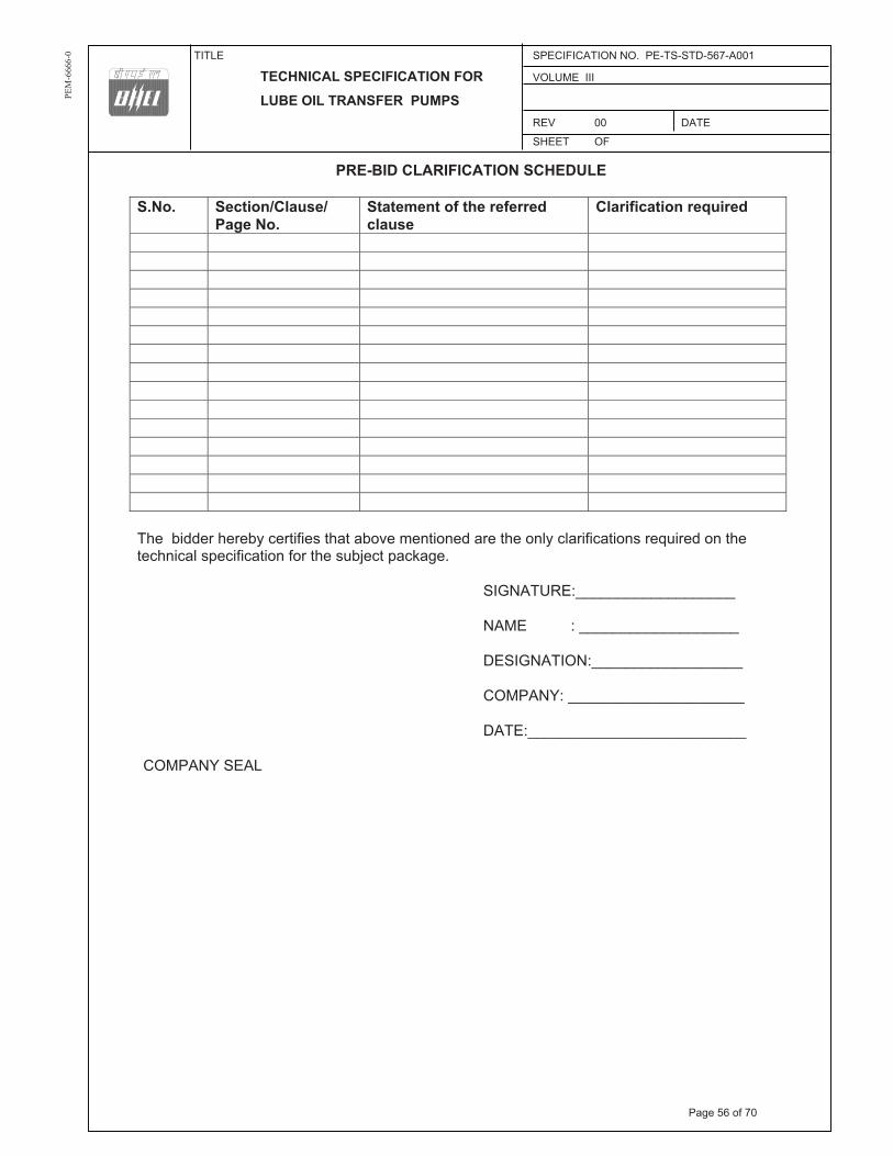
TITLE SPECIFICATION NO. PE-TS-STD-567-A001
TECHNICAL SPECIFICATION FOR VOLUME III
LUBE OIL TRANSFER PUMPS REV 00 DATE
SHEET OF
PEM
-666
6-0
PRE-BID CLARIFICATION SCHEDULE
S.No. Section/Clause/ Page No.
Statement of the referred clause
Clarification required
The bidder hereby certifies that above mentioned are the only clarifications required on the technical specification for the subject package.
SIGNATURE:___________________
NAME : ___________________
DESIGNATION:__________________
COMPANY: _____________________
DATE:__________________________
COMPANY SEAL
Page 56 of 70

SL NO
VOULME/ SECTION
PAGE NO. CLAUSE NO.
TECHNICAL SPECIFICATION/
TENDER DOCUMENT
COMPLETE DESCRIPTION OF DEVIATION
COST OF WITHDRAWL
OF DEVIATION
REFERENCE OF PRICE SCHEDULE ON WHICH COST
OF WITHDRAWL OF DEVIATION IS APPLICABLE
NATURE OF COST OF
WITHDRAWL OF DEVIATION (POSITIVE/ NEGATIVE)
2. For directly dispatchable items, cost of withdrawl of deviation will be applicable on the basic price including taxes, duties & freight.
9. For deviations w.r.t. Payment terms, Liquidated damages, Firm prices and submission of E1/ E2 forms before claiming 10% payment, if a bidder chooses not to give any cost of withdrawl of deviation loading as per Annexure-VIII of GCC, Rev-06 will apply. For any other deviation mentioned in un-priced copy of this format submitted with Part-I bid but not mentioned in priced copy of this format submitted with Priced bid, the cost of withdrawl of deviation shall be taken as NIL.
8. Bidders to note that any deviation (technical/commercial) not listed in above and asked after Part-I opening shall not be considered.
3. All the bidders have to list out all their Technical & Commercial Deviations (if any) in detail in the above format.
4. Any deviation not mentioned above and shown separately or found hidden in offer, will not be taken cognizance of.
5. Bidder shall submit duly filled unpriced copy of above format indicating "quoted" in "cost of withdrawl of deviation" column of the schedule above along with their Techno-commercial offer, wherever applicable.
6. Bidder shall furnish price copy of above format along with price bid.
7. The final decision of acceptance/ rejection of the deviations quoted by the bidder shall be at discretion of the Purchaser.
COMMERCIAL DEVIATIONS
TENDER ENQUIRY REFERENCE:-
10. Any deviation mentioned in priced copy of this format, but not mentioned in the un-priced copy, shall not be accepted.
NAME DESIGNATIONS SIGN & DATE
DEVIATION SHEET (COST OF WITHDRAWL)
PROJECT:- 1x500MW FGUTPP UNCHAHAR
PACKAGE:- LUBE OIL TRANSFER PUMPS
NAME OF VENDOR:-
TECHNICAL DEVIATIONS
REASON FOR QUOTING DEVIATION
13. In case nature of cost of withdrawl (positive/negative) is not specified it shall be assumed as positive.
14. In case of descrepancy in the nature of impact (positive/ negative), positive will be considered for evaluation and negative for ordering.
11. All techno-commercial terms and conditions of NIT shall be deemed to have been accepted by the bidder, other than those listed in unpriced copy of this format.
PARTICULARS OF BIDDERS/ AUTHORISED REPRESENTATIVE
12. Cost of withdrawl is to be given seperately for each deviation. In no event bidder should club cost of withdrawl of more than one deviation else cost of withdrawl of such deviations which have been clubbed together shall be considered as NIL.
NOTES:1. For self manufactured items of bidder, cost of withdrawl of deviation will be applicable on the basic price (i.e. excluding taxes, duties & freight) only.
Page 1 of 1Page 57 of 70

TITLE SPECIFICATION NO. PE-TS-STD-567-A001
DATA SHEET VOLUME III
FOR LUBE OIL PUMPS SECTION
REV 01 DATE 25.06.2014
SHEET 1 of 5
PEM
-666
6-0
“*” marked details will be furnished by the bidder for review and approval by customer 1.00 Project Information
1.01 Enquiry No. *
1.02 Project *
2.00 Service Condition
2.01 Service Clean Oil/ Dirty Oil/Drain Oil (*bidder totick mark the applicable service)
2.02 No. of units *
2.03 Location Indoor
2.04 Duty Intermittent
3.00 Operating Condition
3.01 Liquid to be pumped Turbine Lube Oil
3.02 Pumping Temperature Ambient/70°C
3.03 Viscosity
a) Highest 140cSt @20°C
b) Lowest 28cSt @50°C
c) Normal 48cSt @37.8°C
3.04 Design Viscosity of oil (cSt) 28cSt for capacity , 140cSt for powerconsumption
3.05 Specific Gravity 0.9 gm/cc
3.06 Suction Conditions available Flooded
3.07 i) Rated capacity (LPM) * ii) Pump Maximum flow (LPM) & corresponding head (kg/cm2 (g) ) *
3.08 Rated head – kg/cm2 (g) *
3.09 R..V.Press.Setting *
4.00 Pump
4.01 Manufacturer *
4.02 Type External gear with herringbone gears
4.03 Model No. *
4.04 (i) Design & Manufacturing Standard API 676
4.04 (ii) Testing Standard HIS (ANSI/HI-3.6-2000 / VDMA 24284 , Accuracy Class-2, Group-II
Page 58 of 70

TITLE SPECIFICATION NO. PE-TS-STD-567-A001
DATA SHEET VOLUME III
FOR LUBE OIL PUMPS SECTION
REV 01 DATE 25.06.2014
SHEET 2 of 5
PEM
-666
6-0
(* Bidder to tick the standard adopted)
4.05 Rotation (Viewed from pump shaft end) *
4.06 Shut off head, if applicable Not applicable
4.07 Suction flange Size 80 NB for pump capacity 5000 LPM and above, 50 NB for pump capacity 2880 and 2640 LPM
Standard ANSI B 16.5 Rating 150 lb Facing RF Location (as viewed from drive end) -*(Bidder to tick
the applicable) Top End Side
4.08 Discharge flange Size 80 NB for pump capacity 5000 LPM and above, 50 NB for pump capacity 2880 and 2640 LPM
Standard ANSI B 16.5 Rating 150 lb Facing RF Location (as viewed from drive end) -*(Bidder to tick
the applicable)
4.09 Timing Gear Not applicable for gear pumps
4.10 Relief Valve Built-in
a) Manufacturer Pump manufacturer (OEM)
b) Type *
c) Size (NB) *
d) Capacity, litre/min 110% of the pump max. flow
e) Valve, setting pressure adjustable Yes/No ( * bidder to indicate the applicable) & range of adjustability, in case adjustable - *
f) Material
g) Spring, Material Spring Steel
h) Relief valve cover-Material Same as MOC of pump body
i) Bonnet-Material Same as MOC of pump body
4.11 Shaft Sealing Mechanical seal
4.12 Bearing
a) Type *
b) Nos. Provided *
c) Method of lubrication * d) Temperature rise over *
oil temperature
Page 59 of 70

TITLE SPECIFICATION NO. PE-TS-STD-567-A001
DATA SHEET VOLUME III
FOR LUBE OIL PUMPS SECTION
REV 01 DATE 25.06.2014
SHEET 3 of 5
PEM
-666
6-0
4.13 Type of Coupling *
4.14 Type of Impeller External gear- Herringbone profile
4.15 BHP consumed at Rated viscosity (at pump shaft) *
4.16 BHP consumed at Max. viscosity (at pump shaft) *
4.17 BHP consumed at Min. viscosity (at pump shaft) *
4.18 BHP consumed at the R.V. Set Pressure (at pump shaft) @ 48 cSt * at maximum value of set pressure range
4.19 Pump Efficiency at rated condition @ 48 cSt
a) Mechanical *
b) Volumetric *
c) Overall *
4.20 Recommended motor rating at 50 º C ambient (kw) *
4.21 Motor RPM *
4.22 Design pressure of the pump body and end covers - kg/cm2 (g)- * (Should be at least 6 kg/cm2 (g) )
5.00 Material of Construction
5.01 Casing and End covers ASTM A 216 WCB
5.02 VOID
5.03 Rotor/Gear EN-8 BS 970 Part-I Hardness- * 5.04 Shaft/Shaft Sleeve SS 316
5.05 Seal *
5.06 Gasket GRAFOIL/ Any other asbestos free material subject to customer acceptance (* bidder to indicate)
5.07 Bearing *
5.08 Relief Valve Components *
5.09 Base Plate MS to IS 2062
6.00 Spares
6.01 Commissioning Spares 1 set of gaskets/1 no. gasket compound tube
1 No. mechanical seal
6.02 Essential Spares for Pump, if applicable * (Project specific)
Page 60 of 70

TITLE SPECIFICATION NO. PE-TS-STD-567-A001
DATA SHEET VOLUME III
FOR LUBE OIL PUMPS SECTION
REV 01 DATE 25.06.2014
SHEET 4 of 5
PEM
-666
6-0
6.03 Essential Spares for Motor, if applicable * (Project specific)
6.04 Recommended Spares for Pump for 3 Years *
6.05 Recommended Spare for Motor for 3 Years *
7.00 Weight of
7.01 Pump *
7.02 Motor *
7.03 Base plate *
7.04 Other Accessories (Please specify) *
8.00 Strainer/Filter
8.01 Manufacturer * Bhatia Engineering Company/ FiltrationEngineers (I) Pvt.Ltd / Jaypee Industries Pvt. Ltd./Multitex Filtration Engineers/Otoklin Plants & Equipment Ltd/ OEM subject to condition that strainerof similar type & capacity have beenworking satisfactorily at least two plants.( Bidder to tick the make considered)
8.02 Type & Size * (Type -Project specific; size –to match pump suction)
8.03 Nos. provided * (Project specific)
8.04 Size of Screen mesh & wire dia (min) 40 mesh & 34 SWG
8.05 Design Pressure (kg/cm2) * (Should be at least 4 kg/cm2 )
8.06 Capacity (LPM) To match pump flow
8.07 Design Viscosity 140cSt @ 20 °C
8.08 End Connection Flanged ANSI B 16.5, Class –150 lb
8.09 Maximum Pressure drop at design
Page 61 of 70

TITLE SPECIFICATION NO. PE-TS-STD-567-A001
DATA SHEET VOLUME III
FOR LUBE OIL PUMPS SECTION
REV 01 DATE 25.06.2014
SHEET 5 of 5
PEM
-666
6-0
viscosity (kg/cm2)
a) Clean *
b) Dirty (50% clogged) *
8.10 Material of construction
a) Strainer body *
b) Screen SS316
c) Gaskets GRAFOIL/ Any other asbestos free material subject to customer acceptance (* bidder to indicate)
8.10 a) Inlet pipe Area *
b) Free straining area * c) Ration of Free straining area to inlet pipe area *
( should be > 6:1)
9.00 Accessories to be provided
Common base plate Yes- MS fabricated from IS 2062 plate Common for pump & motor
Coupling & Coupling Guard Yes
Foundation bolts & nuts Yes
Flanges & Companion flanges Yes, Class 150 lb, RF to ANSI B 16.5
Nuts, bolts & gaskets Yes
Lifting lugs, Eye bolts etc Yes
Name plate for all the equipment Yes
Page 62 of 70

TITLE
MOTOR
DATA SHEET - C
SPECIFICATION NO.
VOLUME II B SECTION D REV NO. 00 DATE SHEET 1 OF 2
NAME OF VENDOR
SEAL REV.
NAME SIGNATURE DATE
S.No.
Description Data to be filled by successful bidder
A. General
1 Manufacturer & country of origin
2 Motor type
3 Type of starting
4 Name of the equipment driven by motor & Quantity
5 Maximum Power requirement of driven equipment
6 Rated speed of Driven Equipment
7 Design ambient temperature
B. Design and Performance Data
1 Frame size & type designation
2 Type of duty
3 Rated Voltage
4 Permissible variation for
5 a Voltage
6 b Frequency
7 c) Combined voltage & frequency
8 Rated output at design ambient temp (by resistance method)
9 Synchronous speed & Rated slip
10 Minimum permissible starting voltage
11 Starting time in sec with mechanism coupled
12 a) At rated voltage
13 b) At min starting voltage
14 Locked rotor current as percentage of FLC (including IS tolerance)
15 Torque
a) Starting
b) Maximum
16 Permissible temp rise at rated output over ambient temp & method
17 Noise level at 1.0 m (dB
18 Amplitude of vibration
19 Efficiency & P.F. at rated voltage & frequency
a) At 100% load
c) At 75% load
Page 63 of 70

TITLE
MOTOR
DATA SHEET - C
SPECIFICATION NO.
VOLUME II B SECTION D REV NO. 00 DATE SHEET 2 OF 2
NAME OF VENDOR
SEAL REV.
NAME SIGNATURE DATE
S.No.
Description Data to be filled by successful bidder
c) At starting
C. Constructional Features
1 Method of connection of motor driven equipment
2 Applicable Standard
3 DOP of Enclosure
4 Method of cooling
5 Class of insulation
6 Main terminal box
a) Type
b) Power Cable details (Conductor, size, armour/unarmour)
c) Cable Gland & lugs details (Size, type & material)
d) Permissible Fault level ( kArms & duration in sec)
7 Space heater details (Voltage & watts)
8 Flame proof motor details (if applicable)
a) Enclosure
b) suitability for hazardous area i Zone O / I / II
ii Group IIA / IIB / IIC
9 No. of Stator winding
10 Winding connection
11 Kind of rotor winding
12 Kind of bearings
13 Direction of rotation when viewed from NDE
14 Paint Shade & type
15 Net weight of motor
16 Outline mounting drawing No (To be enclosed as annexure)
D. Characteristic curves/ drawings(To be enclosed for motors of rating � 55KW)
a) Torque speed characteristic
b) Thermal withstand characteristic
c) Current vs time
d) Speed vs time
Page 64 of 70

LOA
D T
ITLE
RA
TIN
G (K
W /
A)
UNIT (U)/STN (S)
Nos
.
VOLTAGE CODE* FEEDER CODE** EMER. LOAD (Y) CONT.(C)/ INTT.(I)
STARTING TIME >5 SEC (Y)
LOC
ATI
ON
B
OA
RD
N
O.
CA
BLE
BLOCK CABLE DRG. No.
CO
NTR
OL
CO
DE
REM
AR
KS
LOA
D N
o.
NA
ME
PLA
TE
MA
X.
CO
NT.
DEM
AN
D
(MC
R)
RUNNING STANDBY
SIZE
CO
DE
NO
s
1 2
3 4
56
78
910
11
12
13
14
15
16
17
18
19
NO
TE
S:1.
CO
LUM
N 1
TO
12
& 1
8 SH
ALL
BE
FILL
ED B
Y TH
E R
EQU
ISIT
ION
ER (O
RIG
INA
TIN
G A
GEN
CY)
; REM
AIN
ING
CO
LUM
NS
AR
E TO
BE
FILL
ED U
P B
Y PE
M (E
LEC
TRIC
AL)
2.
AB
BR
EVIA
TIO
NS
: * V
OLT
AG
E C
OD
E (7
):- (a
c) A
=11
KV,
B=6
.6 K
V, C
=3.3
KV,
D=4
15 V
, E=2
40 V
(1 P
H),
F=11
0 V
(cc)
: G=2
20 V
, H=1
10 V
, J=4
8 V,
K=+
24V,
L=-
24 V
: *
* FEE
DER
CO
DE
(8):-
U=U
NID
IREC
TIO
NA
L ST
AR
TER
, B=B
I-DIR
ECTI
ON
AL
STA
RTE
R, S
=SU
PPLY
FEE
DER
, D=S
UPP
LY F
EED
ER (C
ON
TAC
TER
CO
NTR
OLL
ED)
LOA
D D
ATA
(E
LEC
TRIC
AL)
JOB
NO
.40
1O
RIG
INAT
ING
AG
ENC
YPE
M (E
LEC
TRIC
AL)
PRO
JEC
T TI
TLE
1X
500
MW
FGU
TPP,
U
NC
HA
HA
R
NA
ME
DA
TA F
ILLE
D U
P O
N
SYST
EMLU
BE
OIL
TR
. PU
MPS
SIG
N.
DA
TA E
NTE
RED
ON
DEP
TT. /
SEC
TIO
NEL
ECTR
ICA
LSH
EET
1O
F 1
REV
. 00
DE’
S SI
GN
. & D
ATE
AN
NE
XU
RE
-II
Pag
e 65
of 7
0
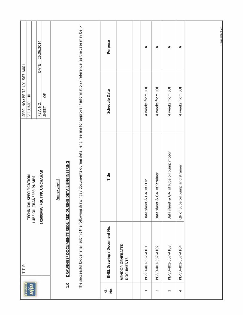
�
TITLE:�
TECH
NICAL
�SPE
CIFICA
TION�
������������������������������������������������������LU
BE�OIL�TRA
NSFER
�PUMPS�
1X50
0MW�FGUTP
P,�UNCH
AHAR
�
SPEC
.�NO.:�PE�TS�40
1�56
7�A0
01�
VOLU
ME:����III�
� REV.�NO.�������������������������������D
ATE�����25.06
.201
4�SH
EET���������O
F������
����������������������������������������������������������������������������������������������������������Ann
exure�III�
� ������������1.0������D
RAWINGS/�DOCU
MEN
TS�REQ
UIRED
�DURING�DETAIL�EN
GINEERING�
�����������The
�successful�bidde
r�shall�subm
it�the�following�draw
ings�/�do
cumen
ts�during�de
tail�en
gine
ering�for�a
pproval�/�inform
ation�/�referen
ce�(as�the
�case�may�be):���
� �
Sl.��
No.�
BHEL�Drawing�/�Do
cumen
t�No.�
Title
�Sche
dule�Date�
Purpose��
��VE
NDO
R�GEN
ERAT
ED�
DOCU
MEN
TS��
����
��
����
����
��
1�PE�V0�40
1�56
7�A1
01�
Data�sh
eet�&
�GA��of�LOP�
4�weeks�from
�LOI�
A�
2�PE�V0�40
1�56
7�A1
02�
Data�sh
eet�&
�GA��of�Straine
r�4�weeks�from
�LOI�
A�
3�PE�V0�40
1�56
7�A1
03�
Data�sh
eet�&
�GA��of�lub
e�oil�pum
p�motor�
4�weeks�from
�LOI�
A�
4�PE�V0�40
1�56
7�A1
04�
QP�of�Lub
e�oil�pum
p�and�strainer�
4�weeks�from
�LOI�
A�
� � � � �P
age
66 o
f 70

�
TITLE:�
TECH
NICAL
�SPE
CIFICA
TION�
������������������������������������������������������LU
BE�OIL�TRA
NSFER
�PUMPS�
1X50
0MW�FGUTP
P,�UNCH
AHAR
�
SPEC
.�NO.:�PE�TS�40
1�56
7�A0
01�
VOLU
ME:����III�
� REV.�NO.�������������������������������D
ATE�����25.06
.201
4�SH
EET���������O
F������
������������������������NOTE�:.�Dwg/�Docum
ent�shall�be
�uploade
d�by�th
e�successful�bidde
r�on�WRE
NCH
�/DMS.Proced
ure�for�the
�same�will�be�inform
ed�after�award�of�����
contract.�����������������������������������������������
� � ������������������������������CO
MPA
NY�SEAL�
� � � � �
SIGN
ATURE
��:___________________�
� NAM
E����������:�___________________�
� DESIGNAT
ION:�__________________�
� COMPA
NY:������_____________________�
� DATE:�������������__________________________�
� � �P
age
67 o
f 70

TITLE:TECHNICAL SPECIFICATION
COMPLIANCE CUM CONFIRMATION CERTIFICATE
LUBE OIL TRANSFER PUMPS
1X500MW FGUTPP, UNCHAHAR
SPEC. NO.: PE-TS-401-567-A001 VOLUME: IIISECTION: REV. NO. DATE 25.06.2014 SHEET 1 OF 2
COMPLIANCE CUM CONFIRMATION CERTIFICATE
The bidder shall confirm compliance with following by signing/ stamping this compliance certificate (every sheet) and furnish same with the offer.
a) The scope of supply, technical details, construction features, design parameters etc. shall be as per technical specification & there are no exclusions other than those mentioned under “exclusion” in section C and those resolved as per ‘Schedule of Deviations’, if applicable, with regard to same.
b) There are no other deviations w.r.t. specifications other than those furnished in the ‘Schedule of Deviations’. Any other deviation, stated or implied, taken elsewhere in the offer stands withdrawn unless specifically brought out in the ‘Schedule of Deviations’.
c) Bidder shall submit QP in the event of order based on the guidelines given in the specification & QP enclosed therein. QP will be subject to BHEL/ CUSTOMER approval & customer hold points for inspection/ testing shall be marked in the QP at the contract stage. Inspection/ testing shall be witnessed as per same apart from review of various test certificates/ Inspection records etc. This shall be within the contracted price with no extra implications to BHEL after award of the contract.
d) All drawings/ data-sheets/ calculations etc. submitted along with the offer shall be considered for reference only, same shall be subject to BHEL/ CUSTOMER approval in the event of order.
e) The offered materials shall be either equivalent or superior to those specified in the specification & shall meet the specified/ intended duty requirements. In case the material specified in the specifications is not compatible for intended duty requirements then same shall be resolved by the bidder with BHEL during the pre - bid discussions, otherwise BHEL/ Customer’s decision shall be binding on the bidder whenever the deficiency is pointed out.
For components where materials are not specified, same shall be suitable for intended duty, all materials shall be subject to approval in the event of order.
f) The commissioning spares shall be supplied on ‘As Required Basis’ & prices for same included in the base price itself.
g) All sub vendors shall be subject to BHEL/ CUSTOMER approval in the event of order.
h) In the event of order, all the material required for completing the job at site shall be supplied by the bidder within the ordered price even if the same are additional to approved billing break up, approved drawing or approved Bill of quantities. This clause will apply in case during site commissioning additional requirements emerges due to customer and/ or consultant’s comments. No extra claims shall be put on this account.
i) The vendor shall guarantee the material and workmanship of all equipment as well as the operation of the pump as per requirement of the specification. The vendor shall also guarantee for each pump the discharge pressure at the specified rated capacity and also corresponding efficiency, brake horsepower and relief valve set pressure.
Page 68 of 70

TITLE:TECHNICAL SPECIFICATION
COMPLIANCE CUM CONFIRMATION CERTIFICATE
LUBE OIL TRANSFER PUMPS
1X500MW FGUTPP, UNCHAHAR
SPEC. NO.: PE-TS-401-567-A001 VOLUME: IIISECTION: REV. NO. DATE 25.06.2014 SHEET 2 OF 2
j) Schedule of drawings submissions, comment incorporations & approval shall be as stipulated in the specifications. The successful bidder shall depute his design personnel to BHEL’s/ Customer’s/ Consultant’s office for across the table resolution of issues and to get documents approved in the stipulated time.
k) As built drawings shall be submitted as and when required during the project execution.
l) Dwg/ Document shall be uploaded by the successful bidder on WRENCH /DMS.Procedure for the same will be informed after award of contract.
m) The bidder has not tempered with this compliance cum confirmation certificate and if at any stage any tempering in the signed copy of this document is noticed then same shall be treated as breach of contract and suitable actions shall be taken against the bidder.
SIGNATURE:___________________
NAME : ___________________
DESIGNATION:__________________
COMPANY: _____________________
DATE:__________________________
COMPANY SEAL
Page 69 of 70

S.N
oD
etai
ls o
f Wor
ks o
r Equ
ipm
ent/S
yste
mQ
UA
NTI
TY E
X-W
OR
KS
DU
LY P
AC
KED
EXC
ISE
DU
TY
INC
L. E
DU
. C
ESS
CST
F
REI
GH
T
TO
TAL
FOR
SI
TE
12
34
5 6
7 8=
4+5+
6+7
1.00
Tota
llum
psum
firm
pric
ein
clus
ive
ofal
ltax
esdu
ties
and
othe
rle
vies
asap
plic
able
for
desi
gn,
engi
neer
ing,
man
ufac
turin
g,in
spec
tion
and
test
ing
atm
anuf
fact
urer
'sw
orks
,pai
ntin
g,su
pply
/del
iver
ydu
lypa
cked
atpr
ojec
tsite
forT
wo(
2)no
s.ea
chof
follo
win
gpu
mp
&m
otor
setd
uly
coup
led
and
uniti
sed
ona
com
mon
base
fram
ew
ithco
uplin
ggu
ard,
foun
datio
nbo
lts,
flang
es,
com
pani
onfla
nges
with
nuts
bolts
and
gask
ets,
drip
pan
with
plug
ged
drai
ning
arra
ngem
ent
with
one
seto
fco
mm
issi
onin
gsp
ares
com
pris
ing
ofon
eno
.mec
hani
cals
eala
ndon
eno
.gas
ketc
ompo
und
tube
/one
setg
aske
tfo
rpu
mp
and
stra
iner
,as
per s
peci
ficat
ion
no. P
E-T
S-4
01-5
67-A
001
a)R
ated
Cap
acity
8250
LPH
and
rate
ddi
scha
rge
pres
sure
as2
kg/c
m2
(g) t
o 3
kg/c
m2
(g)
, inl
et/o
utle
t siz
e as
80
NB
/80N
B2
2.00
Tota
llum
psum
firm
pric
ein
clus
ive
ofal
ltax
esdu
ties
and
othe
rle
vies
asap
plic
able
for
desi
gn,
engi
neer
ing,
man
ufac
turin
g,in
spec
tion
and
test
ing
atm
anuf
fact
urer
'sw
orks
,pai
ntin
g,su
pply
/del
iver
ydu
lypa
cked
atpr
ojec
tsi
tefo
rTw
o(2
)no
s.ea
chof
follo
win
gst
rain
ers
com
plet
ew
ith fl
ange
s,co
mpa
nion
flan
ges
with
nut
s bo
lts a
nd g
aske
ts, f
ound
atio
nbo
lts(if
appl
icab
le)
with
nuts
and
was
hers
,15
NB
vent
and
drai
nco
nnec
tions
prov
ided
with
CS
ball
valv
es,
15N
Bve
nt&
drai
npi
peea
ch 5
ft lo
ng a
s pe
r spe
cific
atio
n no
. PE
-TS
-401
-567
-A00
1
a)D
uple
xS
train
er-
Rat
edC
apac
ity82
50LP
H,
inle
t/out
let
size
as80
NB
/80N
B2
3.00
TOTA
L PR
ICE
4.0.
0
4.0.
14.
0.2
4.03
Bid
der s
hall
furn
ish
the
pric
e of
all
the
item
s as
indi
cate
d in
the
pric
e sc
hedu
le. B
idde
r's o
ffer s
hall
be li
able
to b
e re
ject
ed in
case
bid
der d
oes
not f
urni
sh th
e sa
me.
SUG
GES
TIVE
PR
ICE
FOR
MA
T
1x50
0 M
W N
TPC
FER
OZ
GA
ND
HI T
PP, U
NC
HA
HA
R -
LUB
E O
IL T
RA
NSF
ER P
UM
PS
NO
TES
Bid
der t
o no
te th
at to
tal p
rice
indi
cate
d ab
ove
at 3
.0.0
sha
ll be
con
side
red
for e
valu
atio
n an
d he
nce
shou
ld b
e co
mpl
ete
in a
ll re
spec
t for
the
full
scop
e de
fined
and
A
ny it
em n
ot in
clud
ed in
the
pric
e qu
oted
abo
ve a
nd s
how
n se
para
tely
will
not
be
take
n co
gniz
ance
of a
nd th
e of
fer s
hall
be li
able
for r
ejec
tion.
1 of
1
Pag
e 70
of 7
0