Embed Size (px)
Citation preview
PROJECT: BROTAS 2 (PR-035/2017) - SSE 13059
Nº DOC:
AMY-17035M-ETE001
TECHNICAL SPECIFICATION FOR EQUIPMENT SUPPLY PRESSURE VESSELS
AMYRIS BRASIL LTDA. PLANT: BROTAS/SP
0 12/07/17 INITIAL EDITION JFVS/JFS EPC
REVISÃO DATA DESCRIÇÃO EXE. APROV.

AMY-17035M-ETE001 Rev0 - PRESSURE VESSELS Página 2 de 19
JFS Engenharia e Consultoria Ltda. Rua Domingos Graziano, 53 – SL 37/38 – Edifício Topázio – Centro – 13.600-718 – Araras/SP Tel.: (19) 3542.1045 / 3541.5624 / 8226.4096 – Email: [email protected]
Contents
1. TARGET .............................................................................................................................. 4
2. DEFINITIONS ..................................................................................................................... 4
3. GENERAL INFORMATION ............................................................................................... 4
4. RESPONSIBILITY .............................................................................................................. 4
5. REFERENCE DOCUMENTS ........................................................................................... 4
6. PROJECT DATA ................................................................................................................ 5
6.1. Project code .................................................................................................................... 5
6.2. Design temperature ........................................................................................................ 5
6.3. Design pressure .............................................................................................................. 5
6.4. Permissible Corrosion .................................................................................................... 6
6.5. Combined Loads............................................................................................................. 6
6.6. Minimum Thicknesses ................................................................................................... 6
6.7. Process conditions for Seed Fermenter (SF) and Main Fermenter (MF) .............. 7
6.7.1. Product ......................................................................................................................... 7
6.4.1 Heat Transfer Conditions .......................................................................................... 7
7. CONSTRUCTIVE FEATURES ......................................................................................... 8
7.1. Brackets ........................................................................................................................... 8
7.1.1. Vertical Equipment ..................................................................................................... 8
7.1.2. Horizontal Equipment ................................................................................................. 8
7.2. Flanged Connections ..................................................................................................... 8
7.3. Nozzles ............................................................................................................................ 8
7.4. Openings and reinforcements ...................................................................................... 9
8. MATERIALS ...................................................................................................................... 10
9. WELDS .............................................................................................................................. 10
10. SURFACE FINISH ....................................................................................................... 11
11. PAINTING ...................................................................................................................... 11
12. THERMAL INSULATION ............................................................................................. 11
13. IDENTIFICATION PLATE ........................................................................................... 11
14. TESTS ............................................................................................................................ 12
14.1. Radiographic Examination ...................................................................................... 12
14.2. Hydrostatic Test ........................................................................................................ 13

AMY-17035M-ETE001 Rev0 - PRESSURE VESSELS Página 3 de 19
JFS Engenharia e Consultoria Ltda. Rua Domingos Graziano, 53 – SL 37/38 – Edifício Topázio – Centro – 13.600-718 – Araras/SP Tel.: (19) 3542.1045 / 3541.5624 / 8226.4096 – Email: [email protected]
14.3. Pneumatic Test ......................................................................................................... 13
14.4. Magnetic Particles .................................................................................................... 13
14.5. Strain relief ................................................................................................................ 13
15. EXPEDITING AND INSPECTION.............................................................................. 13
16. PACKAGING AND SHIPMENT .................................................................................. 15
17. DRAWINGS AND DOCUMENTS .............................................................................. 15
18. SUPPLY LIMITS ........................................................................................................... 16
19. CLIMATIC CONDITIONS OF THE PLACE OF INSTALLATION .......................... 17
20. SUBMITTAL DATASHEET ......................................................................................... 17
21. TECHNICAL SUBMITTAL TRANSMITTAL: ............................................................. 19
22. COMMERCIAL SUBMITTAL TRANSMITTAL: ........................................................ 20

AMY-17035M-ETE001 Rev0 - PRESSURE VESSELS Página 4 de 19
JFS Engenharia e Consultoria Ltda. Rua Domingos Graziano, 53 – SL 37/38 – Edifício Topázio – Centro – 13.600-718 – Araras/SP Tel.: (19) 3542.1045 / 3541.5624 / 8226.4096 – Email: [email protected]
1. TARGET
The target of this specification is to collect available information as much as
possible to allow the Manufacturer to supply of pressure vessels, in according with the
requirements of the CONTRACTOR. However, at no time, the manufacturer must feel
prevented from using your best "know-how" in order to obtain a proper product at the
lowest cost.
2. DEFINITIONS
For the purpose of this specification, the terms listed below must be used with
the following settings:
CONTRACTOR – AMYRIS;
TENDERER – Undertaking company which presents the proposal for execution
of the works and/or provision of equipment/materials.
SUPPLIER - Company that won the contract for the execution of the services
object of this specification.
3. GENERAL INFORMATION
This specification is an integral and complementary description to the
"EQUIPMENT DATASHEET", hereinafter called the DATASHEET.
In the case of any discrepancy between this specification and the DATASHEET,
the Datasheet data shall prevail, only for this particular equipment.
Any modification regarding the requirements documents and specifications shall
be clearly informed in the proposal by the TENDERER, as well as the reasons which
justify this modification.
4. RESPONSIBILITY
The TENDERER assumes full responsibility for manufacturing, quality of
materials, quality of workmanship and comply with this specification and its references,
as well as full responsibility for mechanical equipment project.
5. REFERENCE DOCUMENTS
The documents listed below are an integral part of this specification.
AMY-17035M-FDT039 – Seed Fermenter SF tank Datasheet, tag
A4611TQ01;

AMY-17035M-ETE001 Rev0 - PRESSURE VESSELS Página 5 de 19
JFS Engenharia e Consultoria Ltda. Rua Domingos Graziano, 53 – SL 37/38 – Edifício Topázio – Centro – 13.600-718 – Araras/SP Tel.: (19) 3542.1045 / 3541.5624 / 8226.4096 – Email: [email protected]
AMY-17035M-FDT040 – Main Fermenter MF tank Datasheet, tag
A4612TQ01;
AMY-17035M-FDT041 – Main Fermenter MF tank Datasheet, tag
A4613TQ01;
AMY-17035M-FDT044 – Seed Fermenter SF tank Datasheet, tag
A4621TQ01;
AMY-17035M-FDT045 – Main Fermenter MF tank Datasheet, tag
A4622TQ01;
AMY-17035M-FDT046 – Main Fermenter MF tank Datasheet, tag
A4623TQ01;
Any deviation of requirements documents and specifications shall be clearly
informed on proposed by the Tenderer.
6. PROJECT DATA
6.1. Project code
The pressure vessel shall be designed, manufactured, tested and inspected
mainly according to the latest edition of the ASME Code Section VIII Division 1 and the
sanitary standard EHEDG for internal parts in contact with the product. The Brazilian
standards, NR-13 in particular, will be followed by the TENDERER.
6.2. Design temperature
The temperature project will be set up in the Tank DATASHEET, by the
CONTRACTOR. Otherwise, the TENDERER need to set it up, according the
application of the system equipment. However, the design temperature shall be at least
equal to the maximum operating temperature of the fluid for internal uncoated
equipment. For equipment with internal insulating coating, the tank design temperature
will take into account the temperature loss through the insulator.
6.3. Design pressure
The design pressure shall be specified by the CONTRACTOR and will be at
least 10% above the maximum operating pressure, but not less than 1 kgf/cm ² gauge.

AMY-17035M-ETE001 Rev0 - PRESSURE VESSELS Página 6 de 19
JFS Engenharia e Consultoria Ltda. Rua Domingos Graziano, 53 – SL 37/38 – Edifício Topázio – Centro – 13.600-718 – Araras/SP Tel.: (19) 3542.1045 / 3541.5624 / 8226.4096 – Email: [email protected]
6.4. Permissible Corrosion
The acceptable corrosion shall be specified by the CONTRACTOR in tank
DATASHEET and will be applied to all parts subjected to pressure which are in contact
with the process fluid.
If the value of permissible corrosion is not specified on the DATASHEET and
the material of the equipment is subject to corrosion, the TENDERER must be adopted
1,6 mm and added to all parts of the equipment, as provided previously.
6.5. Combined Loads
All equipment shall be designed to withstand the effects of probable
combinations of load, as listed in paragraph UG-22 of the ASME code.
Wind loads shall be based on Brazilian Standard ABNT-NBR-6123, unless
otherwise specified and accepted by the CONTRACTOR.
Due to wind and equipment weight (operating and test, a buckling check shall
be made for all vertical equipment and, in any case, the active stress may be higher
than the permissible stress below:
A
y
E t C D
E S
0 03
1 0 004
, ( ) /
, /
where:
A : Allowable stress (Psi)
E : Modulus of elasticity (Psi)
t : Nominal thickness (in)
C : Corrosion thickness (in)
D : Inner diameter (ft)
Sy : Yield stress (Psi)
6.6. Minimum Thicknesses
Parts of the pressure vessel shall have the minimum thicknesses not less than
the calculated value, using the design data defined in DATASHEET. In any case, for
pressure vessels manufactured by carbon steel or alloy steel, the minimum tank
thickness shall not be less than the higher of the following values, excluding the
tolerable corrosion:
AMY-17035M-ETE001 Rev0 - PRESSURE VESSELS Página 7 de 19
JFS Engenharia e Consultoria Ltda. Rua Domingos Graziano, 53 – SL 37/38 – Edifício Topázio – Centro – 13.600-718 – Araras/SP Tel.: (19) 3542.1045 / 3541.5624 / 8226.4096 – Email: [email protected]
(Di + 2540)/1000 ou 5mm
6.7. Process conditions for Seed Fermenter (SF) and Main Fermenter (MF)
6.7.1. Product
The TENDER shall design the inlet process air ring system “sparger” in order to
meet the following boundary conditions:
Oxygen transfer rate (OTR): 150 mmol/liter/hour;
Tank level variation: as indicated on Datasheet;
The product to be agitated has the following features:
Product type: Whole Cell Broth (WCB)
Density: 1100 kg/m3 (with no air dissolved);
Dynamic viscosity: 3,0 a 100,0 cP (with no air dissolved);
Specific heat: 1,0 kcal/kg/oC
Operating temperature: 30 °C;
Maximum operating pressure for the mechanical seal: 6,5 bar g.
6.4.1 Heat Transfer Conditions
The TENDERER shall also design the agitator to meet the following heat
transfer conditions:
Internal heat generation during fermenter operation:
(a) For Main Fermenter MF 186 m3: 3000 Mcal/h;
(b) For Seed Fermenter SF 39 m3: 750 Mcal/h;
Internal temperature during fermentation shall not exceed: 30 oC;
Available chilled water source for jacket cooling: 4,0 oC
Notes:
1. Setting the air flow in the pipe ("sparger") is the TENDERER's scope;
2. If the TENDERER requires experimental small-scale tests of the
agitation system, AMYRIS can provide, upon request, an 300-liter
fermenter existing in the pilot plant in Campinas – SP.
3. The TENDERER shall inform the calculated chilled water flow rate in
jacket for each fermenter.
AMY-17035M-ETE001 Rev0 - PRESSURE VESSELS Página 8 de 19
JFS Engenharia e Consultoria Ltda. Rua Domingos Graziano, 53 – SL 37/38 – Edifício Topázio – Centro – 13.600-718 – Araras/SP Tel.: (19) 3542.1045 / 3541.5624 / 8226.4096 – Email: [email protected]
7. CONSTRUCTIVE FEATURES
7.1. Brackets
7.1.1. Vertical Equipment
The vertical pressure vessels shall be constructed as self supporting units with
legs, plates or skirts, which shall be calculated in accordance with the conditions of
operation, assembly, and test. Every hole on skirts shall be strengthened structurally,
regardless of the purpose of the same and at least two openings to breathe 100 mm in
diameter and a manway shall be provided for.
7.1.2. Horizontal Equipment
The horizontal pressure vessels must be supported by welded bassinet shape
plate.
7.2. Flanged Connections
Unless contrary instructions on DATASHEET, flanged with integral confined
joints shall be used to connect parts of the same tank shell or/and to have coupling
different equipments.
The finishing of the contact surfaces of the flanges with the board, unless
otherwise specified, shall be the concentric grooves with 1 to 1,5 grooves for mm,
resulting in a 500 RMS maximum roughness (for pressure classes 150 or 300 pounds)
or 250 RMS (for larger classes).
When the equipment is designed with loose flange with ring nut, the
TENDERER must analyse with regard to induced tensions, in the nut as wel as in the
adjacent part of the shell. The nut minimum thickness must not be less than the wall
thickness of a pipe Sch 40 for diameters up to 10" and 9, 5 mm for diameters greater
than 10”.
7.3. Nozzles
Unless contrary instructions on DATASHEET, the neck of nozzles with nominal
diameter up to 10 " shall be done seamless. For neck with nominal diameter equal to or
greater than 12 ", manufacture from sheet of the same shell quality and with the same
efficiency joint.
Unless otherwise stated, the flanged nozzles shall be of the welding neck type.
The dimensions and type of face of the flanges follow ANSI 16.5. The minimum
acceptable rating is 150 pounds.
AMY-17035M-ETE001 Rev0 - PRESSURE VESSELS Página 9 de 19
JFS Engenharia e Consultoria Ltda. Rua Domingos Graziano, 53 – SL 37/38 – Edifício Topázio – Centro – 13.600-718 – Araras/SP Tel.: (19) 3542.1045 / 3541.5624 / 8226.4096 – Email: [email protected]
All nozzles, including manhole, shall be attached to the body of the pressure
vessel by means of total penetration welds and, internally, the manhole end shall face
the inside diameter of the equipment, with a 3 mm rounding radius.
The overlapped type flanges ("slip-on") shall not be used above 400oC (752oF)
working tank temperature.
The holes for screws in flanges shall be symmetrically lagged the main centre of
the equipment lines.
All flanged connections shall be provided with nuts, bolts and gaskets.
All the threads of the screws, nuts and studs must be according to ISO
standard.
7.4. Openings and reinforcements
Openings in the tank side or tank heads shall be reinforced as defined by the
ASME code. The reinforcements shall be designed to ensure that the equipment with
such openings reinforced can withstand the pressure of test and, after get corroded,
the maximum allowable pressure at a temperature of operation.
Preferably, thick-walled nozzles shall used instead of any other nozzle external
reinforcement. If this is necessary, the reinforcement must be of the same material
used in the shell or heads.
The spacing between nozzles or reinforcements and longitudinal welds or the
circumferential shell shall be equal to three times the thickness of the plate of pressure
vessel's shell, but shall not be less than 50 mm.
The reinforcement plates openings shall be designed by the manufacturer of the
equipment for the project specified conditions and with the code compliance. The
material of the reinforcement plates will be the same as the sides or ends to which it is
connected.
Shall be predicted reinforcement for all nozzles and other openings as minimum
requirement dictated by the ASME code. Shall be considered in sizing pipes efforts
strengthening.
Reinforcing plates must have at least one test hole of diameter equal to 1/8"
with DIN thread.
In equipment with a thickness greater than or equal to 20 mm or manufactured
with high-strength steel (ASME VIII div. 1 UHT section), reinforcements of nozzles shall
be as fig. ASME UHT-18.1.
AMY-17035M-ETE001 Rev0 - PRESSURE VESSELS Página 10 de
19
JFS Engenharia e Consultoria Ltda. Rua Domingos Graziano, 53 – SL 37/38 – Edifício Topázio – Centro – 13.600-718 – Araras/SP Tel.: (19) 3542.1045 / 3541.5624 / 8226.4096 – Email: [email protected]
8. MATERIALS
The materials to be used in the manufacture of pressure vessels must be
conform to those specified on the EQUIPMENT DATASHEET.
The minimum quality for external bolts and nuts shall ASTM-A-193-B7 and
ASTM-A-194-2, unless otherwise specified.
All internal screws and nuts must be selected in compliance with the internal
construction materials.
The cleaning and removal of defects in stainless steel parts must be made
using slag removers or abrasive disks of aluminum oxide or silicon carbide with resin or
rubber pellets, or stainless steel brushes that have not been used previously on
material other than stainless steel.
In vertical pressure vessels made of stainless steel, the top of the skirt (100 to
200 mm high) shall be made of the same material of the equipment shell.
In horizontal pressure vessels made of stainless steel, the support plate of the
cribs shall be constructed from the same side of the material equipment.
The materials of components that will be soldiers to the tank shell or, such as
heads, skirts, brackets, cradle saddles, etc., shall be chosen carefully in order to avoid
welding and differential thermal mismatch between the parties.
All the interns of pressure vessels, such as brackets, plates, etc., shall be fixed
to the sides or surfaces by means of continuous fillet welds on both sides. In case of it
may be soldered in one side, welding must be used with full penetration.
9. WELDS
Whenever possible, all longitudinal and circumferential welds of shell, and
heads are tops with full penetration and double cord.
When the equipment does not allow internal welds due to small diameter, they
are allowed simple cord top weld penetration, except when otherwise indicated.
The minimum distance between the ends of the longitudinal welds or equipment
and circumferential weld nozzles, reinforcements, etc. welded to the equipment, it shall
be the greater of the following:
twice the thickness of plate thicker involved in particular or,
50 mm.
The longitudinal welds in adjacent sections of the shell, shall be removed, at
least 300 mm measured on the circumference of the equipment.

AMY-17035M-ETE001 Rev0 - PRESSURE VESSELS Página 11 de
19
JFS Engenharia e Consultoria Ltda. Rua Domingos Graziano, 53 – SL 37/38 – Edifício Topázio – Centro – 13.600-718 – Araras/SP Tel.: (19) 3542.1045 / 3541.5624 / 8226.4096 – Email: [email protected]
Repair of defective welds can be made only with the written report of the
CONTRACTING PARTY, which may or may not designate any inspector to oversee
the work.
All the welds of nozzles in shell or tank heads shall penetrate completely
through the wall of the equipment.
The arrangement of the plates must be done in such a way that all the welds,
circumferential and longitudinal, must be lagged from nozzles and reinforcements.
When using automatic submerged arc welding procedure in main seams of
pressure vessels, the maximum weld deposit shall not exceed 6 mm (1/4 ").
10. SURFACE FINISH
The internal surfaces in contact with the product, whether of the fixed parts of
the pressure vessel parts internal rotóricas shall follow the sanitary recommendations
of EHEDG, as well as having surface finish for eletropolimento with maximum
roughness of 0.8 µm.
11. PAINTING
The surface preparation and paint application shall meet the schema defined by
the painting TENDERER TECHNICAL SPECIFICATIONS.
12. THERMAL INSULATION
When necessary, the pressure vessel must be thermally insulated, when
assemblying in field as defined in the TECHNICAL SPECIFICATION for the supply of
"thermal insulation" of CONTRACTOR. The TENDERER will design and supply all
mechanical features to enable the application of thermal insulation.
13. IDENTIFICATION PLATE
All equipment covered by this specification must be provided with an
identification plate, made of stainless steel, fixed to the substrate in a visible and easily
accessible, with the following data written indelibly:
Name of the manufacturer;
Serial number (manufacturing);
Year of manufacture;
Purchase order number;
Equipment identification;
AMY-17035M-ETE001 Rev0 - PRESSURE VESSELS Página 12 de
19
JFS Engenharia e Consultoria Ltda. Rua Domingos Graziano, 53 – SL 37/38 – Edifício Topázio – Centro – 13.600-718 – Araras/SP Tel.: (19) 3542.1045 / 3541.5624 / 8226.4096 – Email: [email protected]
Project code;
Nominal capacity/total,
Shell diameter (mm);
Distance length between it's ends (mm);
Design and operation temperature (°C);
Design and operation pressure (kgf/cm ²);
Hot maximum working pressure eroded (kgf/cm²);
Permissible corrosion (mm);
Welding joint efficiency;
Weights of equipment, empty, operating and in hydrostatic test (kgf);
14. TESTS
14.1. Radiographic Examination
Whenever required by the code or requested by the CONTRACTOR, shall be
carried out x-ray examinations. The films obtained shall be made available to the
CONTRACTOR for any inspections.
For vessels or sections sideways where top welding joints are 100%
radiographed, all welded joints between shell/nozzles and nozzles/flanges shall be
examined by the method of magnetic particles or liquid penetrant, since authorized by
CONTRACTING oversight. The test shall meet the following requirements:
. Welding joints between neck of nozzles and shell shall be examined
before the installation of any reinforcement;
the inner side of the welding root cord, where applicable, shall be
examined after their preparation for welding, as well as both sides
complete welded;
a final inspection by magnetic particles of welding end shall be
performed after heat treatment after welding, except where the welding
is not accessible, as under strengthening plates.
If it is not specified total radiography shall be carried out partial x-ray of each
welding longitudinal joint and each circumferential joint between adjacent
circumferential joints.
When required by the code or by the inspector, all main welding joints shall be
checked as follows:
total or radiography
magnetic particle examination every weld 1/4 "thick.

AMY-17035M-ETE001 Rev0 - PRESSURE VESSELS Página 13 de
19
JFS Engenharia e Consultoria Ltda. Rua Domingos Graziano, 53 – SL 37/38 – Edifício Topázio – Centro – 13.600-718 – Araras/SP Tel.: (19) 3542.1045 / 3541.5624 / 8226.4096 – Email: [email protected]
14.2. Hydrostatic Test
All equipment shall be hydrostatically tested according to requirements of the
code. However, the test conditions shall be, as a minimum, the following:
Test fluid: treated water;
Test pressure: according to ASME code, but at least equal to the
operating pressure, measured at the highest point of the equipment in
operation position;
Fluid temperature: 20° C (but never less than 16° C);
Test duration: 2 hours for every 25 mm of hoof wall (minimum 2 hours).
After the test, all nozzles must be open, all equipment thoroughly dried and all
the joints used must be exchanged.
14.3. Pneumatic Test
All nozzles reinforcement plates of the shell shall be pneumatically tested with
compressed air to 1 kgf/cm ² man. and foaming agent.
14.4. Magnetic Particles
For vertical equipment supported by skirts and whose length to diameter ratio is
greater than 18, you must have the root and solder end magnetic particle inspected to
ensure the absence of cracks. Alternatively, you can use penetrating fluid testing, since
it allowed for monitoring.
14.5. Strain relief
In equipment with U-shaped tubes whose folding RADIUS is equal to 150 mm,
must be provided for relief from tension in the folding region up to 300 mm of straight
pipe part.
15. EXPEDITING AND INSPECTION
The equipment and/or materials manufacturing described in this specification is
subject to expediting and inspection by the CONTRACTOR and/or who indicated, as
well as the people hired by the CONTRACTOR, as the inspection class indicated
below:
Class A Inspection:
AMY-17035M-ETE001 Rev0 - PRESSURE VESSELS Página 14 de
19
JFS Engenharia e Consultoria Ltda. Rua Domingos Graziano, 53 – SL 37/38 – Edifício Topázio – Centro – 13.600-718 – Araras/SP Tel.: (19) 3542.1045 / 3541.5624 / 8226.4096 – Email: [email protected]
Consists of: receiving inspection without testimony of testing, comprising
certificate exam, visual and dimensional control and verification of packing.
Class B Inspection:
Consists of: receiving inspection with testimony of tests, including as applicable,
examination of certificates of raw material and welding skills, mechanical testing,
hydrostatic tests, calibration tests, tests, tests of electrostatic operation and
performance, non-destructive testing, visual, dimensional controls, painting and
packaging identification and verification.
Class C Inspection:
Consists of: partial follow-up inspection of manufacture including, as applicable,
examination of certificates of raw material and welding qualifications, against raw
material verification tests, monitoring of welding qualifications, heat treatment, non-
destructive testing, machining and Assembly inspections and final tests of intermediate
operation intermediate and final, hydrostatic tests, electrical tests, tests, tests of
electrostatic measurement , performance testing, balancing, visual, dimensional
controls, painting and packaging identification and verification.
Class D Inspection:
Consists of: full follow-up inspection of manufacturing, with the same exams,
tests and controls mentioned in class C.
The elements of the contractor or who he indicate shall have, during the period
of manufacture and within normal working hours, free access to all departments and
sections of the factory where the project and manufacturing activities was performed
on.
It is CONTRACTOR duty to give to the Inspector and any surveyor all the
evidence necessary to enable it to verify the achievement of manufacturing events that
are related to the payment scheme set out in the purchase order.
AMY-17035M-ETE001 Rev0 - PRESSURE VESSELS Página 15 de
19
JFS Engenharia e Consultoria Ltda. Rua Domingos Graziano, 53 – SL 37/38 – Edifício Topázio – Centro – 13.600-718 – Araras/SP Tel.: (19) 3542.1045 / 3541.5624 / 8226.4096 – Email: [email protected]
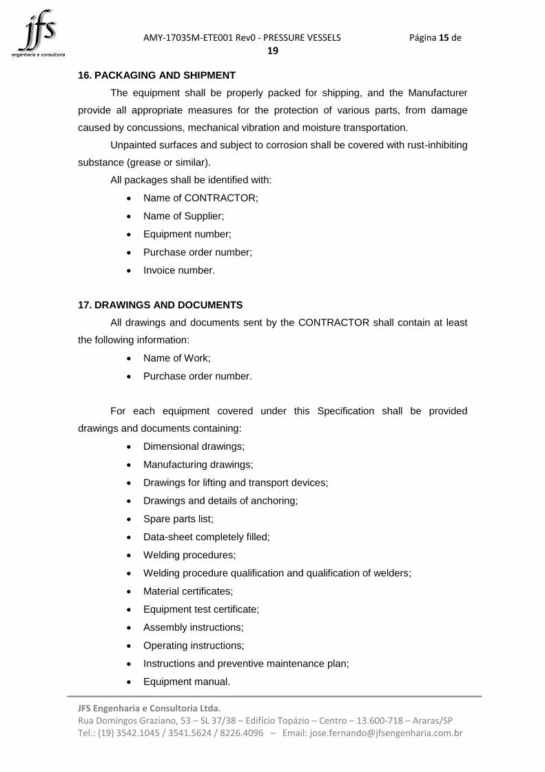
16. PACKAGING AND SHIPMENT
The equipment shall be properly packed for shipping, and the Manufacturer
provide all appropriate measures for the protection of various parts, from damage
caused by concussions, mechanical vibration and moisture transportation.
Unpainted surfaces and subject to corrosion shall be covered with rust-inhibiting
substance (grease or similar).
All packages shall be identified with:
Name of CONTRACTOR;
Name of Supplier;
Equipment number;
Purchase order number;
Invoice number.
17. DRAWINGS AND DOCUMENTS
All drawings and documents sent by the CONTRACTOR shall contain at least
the following information:
Name of Work;
Purchase order number.
For each equipment covered under this Specification shall be provided
drawings and documents containing:
Dimensional drawings;
Manufacturing drawings;
Drawings for lifting and transport devices;
Drawings and details of anchoring;
Spare parts list;
Data-sheet completely filled;
Welding procedures;
Welding procedure qualification and qualification of welders;
Material certificates;
Equipment test certificate;
Assembly instructions;
Operating instructions;
Instructions and preventive maintenance plan;
Equipment manual.

AMY-17035M-ETE001 Rev0 - PRESSURE VESSELS Página 16 de
19
JFS Engenharia e Consultoria Ltda. Rua Domingos Graziano, 53 – SL 37/38 – Edifício Topázio – Centro – 13.600-718 – Araras/SP Tel.: (19) 3542.1045 / 3541.5624 / 8226.4096 – Email: [email protected]
18. SUPPLY LIMITS
Supplying responsibilities, showed in following table, are divided between
TENDERERS and CONTRACTOR:
Item Description CONTRACTOR TENDERER
Pressure vessels
1 Mechanical design of equipment
x
2 Manufacturing and Assembly materials
x
3 Manufacture and Assembly
x
4 Body, bottom and top
x
5 Coil/heating/cooling jacket
x
6 Tank agitation system
x
7 Supporting legs with plates/skirt
x
8 Thermal insulation x
9 Access ladder sailor type N.A. N.A.
10 Outside access platform side visit N.A. N.A.
11 Top platform N.A. N.A.
12 Intermediate resting platform if necessary N.A. N.A.
13 Drawing and dimensions of the bases x
14 Shipment of the equipment in the factory of the
applicant x
15 Transport of equipment to target
CONTRACTOR factory x
16 Transport equipment insurance x
17 Unloading, leveling and securing the
equipment CONTRACTOR's factory x
18 Supervision of installation of the equipment in
the factory of the CONTRACTOR x
19 Hydrostatic testing/tightness in the applicant's
factory x
20 Civil works for the equipment x
21 Manufacturing planning x
AMY-17035M-ETE001 Rev0 - PRESSURE VESSELS Página 17 de
19
JFS Engenharia e Consultoria Ltda. Rua Domingos Graziano, 53 – SL 37/38 – Edifício Topázio – Centro – 13.600-718 – Araras/SP Tel.: (19) 3542.1045 / 3541.5624 / 8226.4096 – Email: [email protected]
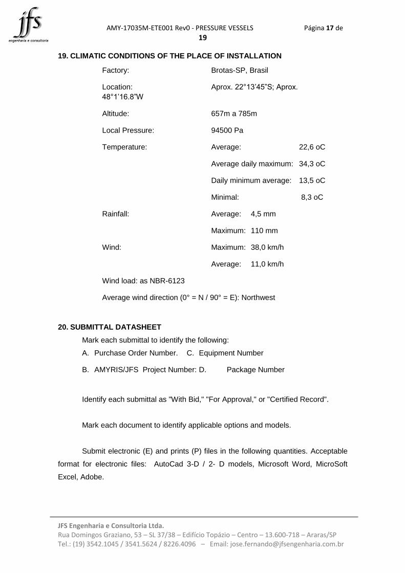
19. CLIMATIC CONDITIONS OF THE PLACE OF INSTALLATION
Factory: Brotas-SP, Brasil
Location: Aprox. 22°13’45”S; Aprox.
48°1’16.8”W
Altitude: 657m a 785m
Local Pressure: 94500 Pa
Temperature: Average: 22,6 oC
Average daily maximum: 34,3 oC
Daily minimum average: 13,5 oC
Minimal: 8,3 oC
Rainfall: Average: 4,5 mm
Maximum: 110 mm
Wind: Maximum: 38,0 km/h
Average: 11,0 km/h
Wind load: as NBR-6123
Average wind direction (0° = N / 90° = E): Northwest
20. SUBMITTAL DATASHEET
Mark each submittal to identify the following:
A. Purchase Order Number. C. Equipment Number
B. AMYRIS/JFS Project Number: D. Package Number
Identify each submittal as "With Bid," "For Approval," or "Certified Record".
Mark each document to identify applicable options and models.
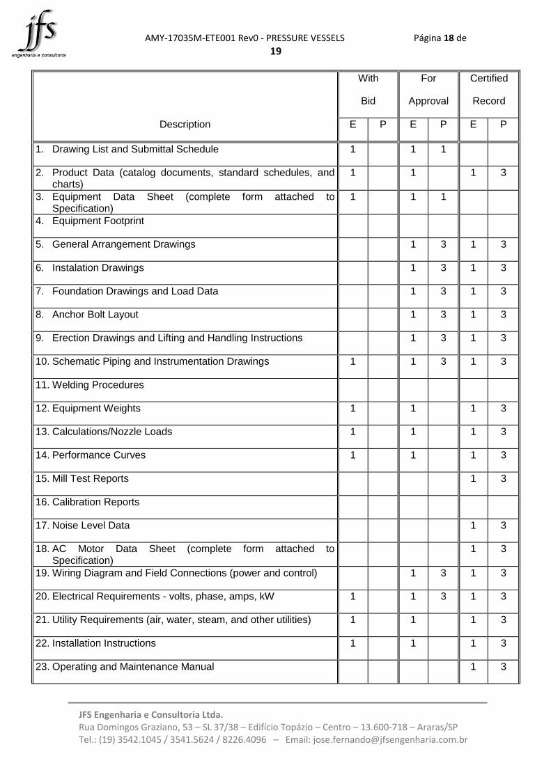
Submit electronic (E) and prints (P) files in the following quantities. Acceptable
format for electronic files: AutoCad 3-D / 2- D models, Microsoft Word, MicroSoft
Excel, Adobe.
AMY-17035M-ETE001 Rev0 - PRESSURE VESSELS Página 18 de
19
JFS Engenharia e Consultoria Ltda. Rua Domingos Graziano, 53 – SL 37/38 – Edifício Topázio – Centro – 13.600-718 – Araras/SP Tel.: (19) 3542.1045 / 3541.5624 / 8226.4096 – Email: [email protected]
With
Bid
For
Approval
Certified
Record
Description E P E P E P
1. Drawing List and Submittal Schedule 1 1 1
2. Product Data (catalog documents, standard schedules, and charts)
1 1 1 3
3. Equipment Data Sheet (complete form attached to Specification)
1 1 1
4. Equipment Footprint
5. General Arrangement Drawings 1 3 1 3
6. Instalation Drawings 1 3 1 3
7. Foundation Drawings and Load Data 1 3 1 3
8. Anchor Bolt Layout 1 3 1 3
9. Erection Drawings and Lifting and Handling Instructions 1 3 1 3
10. Schematic Piping and Instrumentation Drawings 1 1 3 1 3
11. Welding Procedures
12. Equipment Weights 1 1 1 3
13. Calculations/Nozzle Loads 1 1 1 3
14. Performance Curves 1 1 1 3
15. Mill Test Reports 1 3
16. Calibration Reports
17. Noise Level Data 1 3
18. AC Motor Data Sheet (complete form attached to Specification)
1 3
19. Wiring Diagram and Field Connections (power and control) 1 3 1 3
20. Electrical Requirements - volts, phase, amps, kW 1 1 3 1 3
21. Utility Requirements (air, water, steam, and other utilities) 1 1 1 3
22. Installation Instructions 1 1 1 3
23. Operating and Maintenance Manual 1 3
AMY-17035M-ETE001 Rev0 - PRESSURE VESSELS Página 19 de
19
JFS Engenharia e Consultoria Ltda. Rua Domingos Graziano, 53 – SL 37/38 – Edifício Topázio – Centro – 13.600-718 – Araras/SP Tel.: (19) 3542.1045 / 3541.5624 / 8226.4096 – Email: [email protected]
With
Bid
For
Approval
Certified
Record
Description E P E P E P
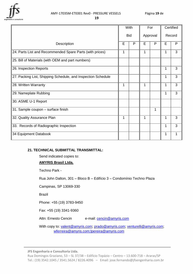
24. Parts List and Recommended Spare Parts (with prices) 1 1 1 3
25. Bill of Materials (with OEM and part numbers)
26. Inspection Reports 1 3
27. Packing List, Shipping Schedule, and Inspection Schedule 1 3
28. Written Warranty 1 1 1 3
29. Nameplate Rubbing 1 3
30. ASME U-1 Report
31. Sample coupon – surface finish 1
32. Quality Assurance Plan 1 1 1 3
33. Records of Radiographic Inspection 1 3
34 Equipment Databook 1 1
21. TECHNICAL SUBMITTAL TRANSMITTAL:
Send indicated copies to:
AMYRIS Brasil Ltda.
Techno Park -
Rua John Dalton, 301 – Bloco B – Edifício 3 – Condomínio Techno Plaza
Campinas, SP 13069-330
Brazil
Phone: +55 (19) 3783-9450
Fax: +55 (19) 3341-9360
Attn: Ernesto Cencin e-mail: [email protected]
With copy to: [email protected]; [email protected]; [email protected];

AMY-17035M-ETE001 Rev0 - PRESSURE VESSELS Página 20 de
19
JFS Engenharia e Consultoria Ltda. Rua Domingos Graziano, 53 – SL 37/38 – Edifício Topázio – Centro – 13.600-718 – Araras/SP Tel.: (19) 3542.1045 / 3541.5624 / 8226.4096 – Email: [email protected]
JFS Engenharia e Consultoria Ltda.
Rua Domingos Graziano, 53 – SL 37/38 – Edifício Topázio – Centro
13.600-718 – Araras/SP
Brazil
Tel.: +55 (19) 3542.1045 / 3541.5624 / 8226.4096
Attn: José Fernando email: [email protected]
With a copy to: [email protected]
22. COMMERCIAL SUBMITTAL TRANSMITTAL:
Send indicated copies to:
AMYRIS Brasil Ltda.
Techno Park -
Rua John Dalton, 301 – Bloco B – Edifício 3 – Condomínio Techno Plaza
Campinas, SP 13069-330
Brazil
Phone: +55 (19) 3783-9450
Fax: +55 (19) 3341-9360
Attn: Elaine Cristina da Silva e-mail: [email protected]
With a copy to: [email protected]; [email protected]; [email protected]