Embed Size (px)
Citation preview

Joint Workings
Technical Specification for 12-24kV Single Phase
Step Voltage Regulator (SVR)
JTS 02-04-01
Technical Specification 12-24 kV Single Phase Step Voltage Regulator
ii Specification JTS02-04-01 Ver 1
Joint Technical Specification between Ergon and ENERGEX
ENERGEX Limited ABN 40 078 849 055 Ergon Energy Corporation Limited ABN 50 087 646 062
Contents
1. PURPOSE AND SCOPE ............................................................................................................. 1
2. LIST OF APPLICABLE STANDARDS ....................................................................................... 2
3. DRAWINGS WITH SPECIFICATION .......................................................................................... 3
4. SERVICE CONDITIONS ............................................................................................................. 5 4.1 Environmental Conditions ................................................................................................. 5 4.2 Functional Characteristics ................................................................................................. 6
5. DESIGN & CONSTRUCTION - OPERATION............................................................................. 7 5.1 General .............................................................................................................................. 7 5.2 Rating ................................................................................................................................ 7 5.3 Regulator Configurations ................................................................................................... 8 5.4 Short Circuit Capacity ........................................................................................................ 8
6. DESIGN & CONSTRUCTION - FITTINGS .................................................................................. 8 6.1 Metering Voltage Transformer and Current Transformer .................................................. 8 6.2 Regulator Mass ................................................................................................................. 8 6.3 Construction ...................................................................................................................... 8 6.4 Lifting Arrangements ......................................................................................................... 9 6.5 Oil Gauges ......................................................................................................................... 9 6.6 Valves ................................................................................................................................ 9 6.7 Pressure Relief and Explosion Venting ............................................................................. 9 6.8 Earthing Stud ..................................................................................................................... 9 6.9 Regulator Mounting ......................................................................................................... 10 6.10 Location of Fittings .......................................................................................................... 10 6.11 Bushings and Connections .............................................................................................. 10 6.12 Surge Arrester Brackets .................................................................................................. 11 6.13 Nameplate ....................................................................................................................... 11 6.14 Insulating Oil .................................................................................................................... 11 6.15 Protective Coating ........................................................................................................... 11
7. DESIGN & CONSTRUCTION - ON LOAD TAP CHANGER .................................................... 13 7.1 On Load Tap Changer Requirements ............................................................................. 13 7.2 On Load Tap Changer Mechanism & Motor Compartment ............................................ 14 7.3 Tap Position Indication .................................................................................................... 15
8. DESIGN & CONSTRUCTION - CONTROL BOX MOUNTING & WIRING .............................. 15 8.1 Control Box Mounting ...................................................................................................... 15 8.2 Secondary Wiring and Cabling ........................................................................................ 16
9. DESIGN & CONSTRUCTION - SCADA & AUTOMATION ...................................................... 16
10. PERFORMANCE & TESTING .................................................................................................. 17 10.1 General ............................................................................................................................ 17 10.2 Inspection ........................................................................................................................ 17 10.3 Type Test Compliance .................................................................................................... 17 10.4 Routine Tests .................................................................................................................. 17 10.5 Acceptance Tests ............................................................................................................ 17 10.6 Witnessing of Tests ......................................................................................................... 17 10.7 Test Certificates ............................................................................................................... 18
Technical Specification 12-24 kV Single Phase Step Voltage Regulator
iii Specification JTS02-04-01 Ver 1
Joint Technical Specification between Ergon and ENERGEX
ENERGEX Limited ABN 40 078 849 055 Ergon Energy Corporation Limited ABN 50 087 646 062
11. GENERAL REQUIREMENTS ................................................................................................... 19 11.1 Special Tools, Gauges and Accessories ......................................................................... 19 11.2 Quality Assurance ........................................................................................................... 19 11.3 Risk Assessment ............................................................................................................. 20 11.4 Load restraint transformer and plant lashing points ........................................................ 20 11.5 Environmental Considerations ........................................................................................ 21 11.6 Reliability ......................................................................................................................... 21 11.7 Traceability ...................................................................................................................... 21 11.8 Sample ............................................................................................................................ 21 11.9 Training ............................................................................................................................ 22 11.10 Drawings and Information to be submitted with the Tender ............................................ 23 11.11 Drawings and Information to be Provided by the Tenderer ............................................ 23 11.12 Quality of Drawings - Drawing Title Block ....................................................................... 24 11.13 Quality of Drawings - Drawing Revisions ........................................................................ 24 11.14 Quality of Drawings - Drawings in Electronic Format ...................................................... 25
ATTACHMENT 1 - SPECIFIC TECHNICAL REQUIREMENTS ...................................................... 26
ATTACHMENT 2 - GUARANTEE TECHNICAL PARTICULARS FOR SVR .................................. 28
ATTACHMENT 3 - GUARANTEE TECHNICAL PLANT CONSTRUCTION DETAILS ................... 31
ATTACHMENT 4 - TECHNICAL RISK ASSESSMENT ................................................................... 34
ATTACHMENT 5 – COMMENTS ON PRODUCT RELIABILITY ..................................................... 36
ATTACHMENT 6 - RATING PLATE DETAILS ................................................................................ 37 Attachment 6A - Rating Plate Details for the SVR - Energex .................................................... 37 Attachment 6B - Rating Plate Details for the SVR – Ergon ....................................................... 39
ATTACHMENT 7 - TECHNICAL DOCUMENTATION CHECKLIST ............................................... 40
Technical Specification 12-24 kV Single Phase Step Voltage Regulator
Page 1 of 40 Specification JTS02-04-01 Ver 1
Joint Manual between ENERGEX and Ergon Energy ENERGEX Limited ABN 40 078 849 055 Ergon Energy Corporation Limited ABN 50 087 646 062
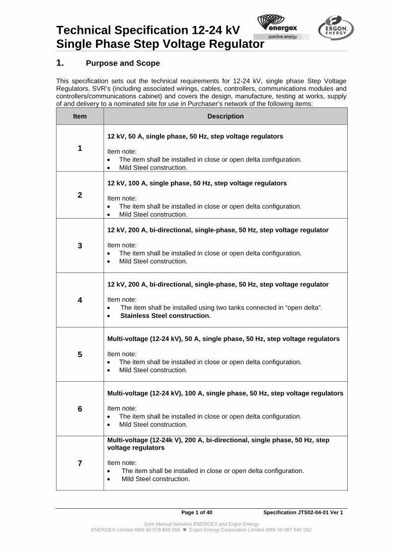
1. Purpose and Scope This specification sets out the technical requirements for 12-24 kV, single phase Step Voltage Regulators, SVR’s (including associated wirings, cables, controllers, communications modules and controllers/communications cabinet) and covers the design, manufacture, testing at works, supply of and delivery to a nominated site for use in Purchaser’s network of the following items:
Item Description
1
12 kV, 50 A, single phase, 50 Hz, step voltage regulators Item note: The item shall be installed in close or open delta configuration. Mild Steel construction.
2
12 kV, 100 A, single phase, 50 Hz, step voltage regulators Item note: The item shall be installed in close or open delta configuration. Mild Steel construction.
3
12 kV, 200 A, bi-directional, single-phase, 50 Hz, step voltage regulator Item note: The item shall be installed in close or open delta configuration. Mild Steel construction.
4
12 kV, 200 A, bi-directional, single-phase, 50 Hz, step voltage regulator Item note: The item shall be installed using two tanks connected in “open delta”. Stainless Steel construction.
5
Multi-voltage (12-24 kV), 50 A, single phase, 50 Hz, step voltage regulators Item note: The item shall be installed in close or open delta configuration. Mild Steel construction.
6
Multi-voltage (12-24 kV), 100 A, single phase, 50 Hz, step voltage regulators Item note: The item shall be installed in close or open delta configuration. Mild Steel construction.
7
Multi-voltage (12-24k V), 200 A, bi-directional, single phase, 50 Hz, step voltage regulators Item note: The item shall be installed in close or open delta configuration. Mild Steel construction.
Technical Specification 12-24 kV Single Phase Step Voltage Regulator
Page 2 of 40 Specification JTS02-04-01 Ver 1
Joint Manual between ENERGEX and Ergon Energy ENERGEX Limited ABN 40 078 849 055 Ergon Energy Corporation Limited ABN 50 087 646 062
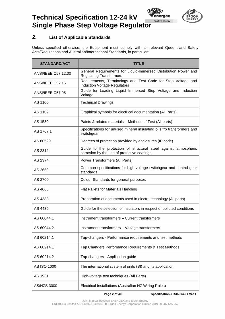
2. List of Applicable Standards Unless specified otherwise, the Equipment must comply with all relevant Queensland Safety Acts/Regulations and Australian/International Standards, in particular:
STANDARD/ACT TITLE
ANSI/IEEE C57.12.00 General Requirements for Liquid-Immersed Distribution Power and Regulating Transformers
ANSI/IEEE C57.15 Requirements, Terminology and Test Code for Step Voltage and Induction Voltage Regulators
ANSI/IEEE C57.95 Guide for Loading Liquid Immersed Step Voltage and Induction Voltage
AS 1100 Technical Drawings
AS 1102 Graphical symbols for electrical documentation (All Parts)
AS 1580 Paints & related materials – Methods of Test (All parts)
AS 1767.1 Specifications for unused mineral insulating oils fro transformers and switchgear
AS 60529 Degrees of protection provided by enclosures (IP code)
AS 2312 Guide to the protection of structural steel against atmospheric corrosion by the use of protective coatings
AS 2374 Power Transformers (All Parts)
AS 2650 Common specifications for high-voltage switchgear and control gear standards
AS 2700 Colour Standards for general purposes
AS 4068 Flat Pallets for Materials Handling
AS 4383 Preparation of documents used in electrotechnology (All parts)
AS 4436 Guide for the selection of insulators in respect of polluted conditions
AS 60044.1 Instrument transformers – Current transformers
AS 60044.2 Instrument transformers – Voltage transformers
AS 60214.1 Tap-changers - Performance requirements and test methods
AS 60214.1 Tap Changers Performance Requirements & Test Methods
AS 60214.2 Tap-changers - Application guide
AS ISO 1000 The international system of units (SI) and its application
AS 1931 High-voltage test techniques (All Parts)
AS/NZS 3000 Electrical Installations (Australian NZ Wiring Rules)

Technical Specification 12-24 kV Single Phase Step Voltage Regulator
Page 3 of 40 Specification JTS02-04-01 Ver 1
Joint Manual between ENERGEX and Ergon Energy ENERGEX Limited ABN 40 078 849 055 Ergon Energy Corporation Limited ABN 50 087 646 062
STANDARD/ACT TITLE
AS/NZS 60137 Insulated bushings for alternating voltages above 1000 V
AS/NZS ISO 31000 Risk Management - Principles and Guidelines
AS/NZS ISO 9001 Quality Management Systems - Requirements
IEC 60721-2-1 Classification of environmental conditions Part 2-1: Environmental conditions appearing in nature - Temperature and humidity
IEC 60721-2-4 Classification of environmental conditions Part 2-4: Environmental conditions appearing in nature - Solar radiation and temperature
Federal/State/Others
Queensland Electrical Safety Act 2002 - Including all Regulations and Codes of Practice
Queensland Work Health & Safety Act 2011 - Including all Regulations and Codes of Practice
If the equipment offered does not comply with Australian Standards, but complies with International Standards, eg IEC, then detailed descriptions shall be given of the differences between the apparatus offered and the Australian Standards specified requirements. NOTE: The Purchaser will not accept equipment that does not comply in full with all relevant Queensland Safety Acts/Regulations.
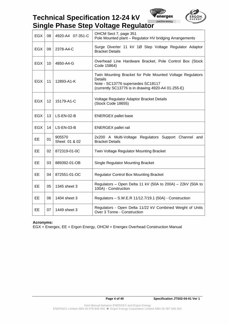
3. Drawings with Specification The following drawings are attached and form part of this specification. Constructional drawings including bracket details are provided for indication and are for quotation purposes only. The Purchaser requires all detail drawings to be submitted as part of the Tender.
REF DRAWING NUMBER
TITLE
EGX 01 4920-A4 01-252-C OHCM Section 1, Page 252 Attachments Hanger Transformer Surge Arrester and Pig Tail
EGX 02 4920-A4 01-255-E OHCM Section 1, Page 255 Attachments 11 kV Regulator and Control Box Bracket to Pole
EGX 03 4920-A4 01-260-H OHCM Section 1, Page 260 Attachments Control Box to Pole
EGX 04 4920-A4 04-09-D OHCM Sect 4, Page 9 11kV construction – 11 T 11 kV termination constructions
EGX 05 4920-A4 04-26-C OHCM Sect 4, page 26 11kV construction – 11BS, 11BS1 11kV bridge support construction (wood pole)
EGX 06 4920-A4 07-255-B OHCM Section 7, Page 255 Pole Mounted Plant - Recloser HV Bridging Sets
EGX 07 4920-A4 07-302-H OHCM Sect 7, Page 302 Pole Mounted Plant - 11REG/200R 11 kV Regulator Station Construction Open Delta (Wood Pole)
Technical Specification 12-24 kV Single Phase Step Voltage Regulator
Page 4 of 40 Specification JTS02-04-01 Ver 1
Joint Manual between ENERGEX and Ergon Energy ENERGEX Limited ABN 40 078 849 055 Ergon Energy Corporation Limited ABN 50 087 646 062
EGX 08 4920-A4 07-351-C OHCM Sect 7, page 351 Pole Mounted plant – Regulator HV bridging Arrangements
EGX 09 2378-A4-C Surge Diverter 11 kV 1Ø Step Voltage Regulator Adaptor Bracket Details
EGX 10 4850-A4-G Overhead Line Hardware Bracket, Pole Control Box (Stock Code 15864)
EGX 11 12893-A1-K
Twin Mounting Bracket for Pole Mounted Voltage Regulators Details Note - SC13776 supersedes SC18117 (currently SC13776 is in drawing 4920-A4 01-255-E)
EGX 12 15179-A1-C Voltage Regulator Adaptor Bracket Details (Stock Code 18655)
EGX 13 LS-EN-02-B ENERGEX pallet base
EGX 14 LS-EN-03-B ENERGEX pallet rail
EE 01 905570 Sheet 01 & 02
2x200 A Multi-Voltage Regulators Support Channel and Bracket Details
EE 02 872319-01-0C Twin Voltage Regulator Mounting Bracket
EE 03 889392-01-OB Single Regulator Mounting Bracket
EE 04 872551-01-OC Regulator Control Box Mounting Bracket
EE 05 1345 sheet 3 Regulators – Open Delta 11 kV (50A to 200A) – 22kV (50A to 100A) - Construction
EE 06 1404 sheet 3 Regulators – S.W.E.R 11/12.7/19.1 (50A) - Construction
EE 07 1449 sheet 3 Regulators - Open Delta 11/22 kV Combined Weight of Units Over 3 Tonne - Construction
Acronyms: EGX = Energex, EE = Ergon Energy, OHCM = Energex Overhead Construction Manual

Technical Specification 12-24 kV Single Phase Step Voltage Regulator
Page 5 of 40 Specification JTS02-04-01 Ver 1
Joint Manual between ENERGEX and Ergon Energy ENERGEX Limited ABN 40 078 849 055 Ergon Energy Corporation Limited ABN 50 087 646 062
4. Service Conditions
4.1 Environmental Conditions
4.1.1 The regulators will be installed outdoors and exposed to the high temperature and humidity conditions experienced in Regional Queensland.
4.1.2 Some regulators will be installed close to ocean beaches and will be exposed to a salt laden atmosphere.
4.1.3 The regulators will be installed outdoors and will be exposed to and shall be able to withstand the following environmental conditions:
CONDITION REQUIREMENTS
Humidity Extended periods of relative humidity, ranging from 10% to 90% (IEC 60721-2-1 Figure 6)
Solar radiation Level 1100 Wm-1 with high ultra violet content (IEC 60721-2-4 Table 1)
Ambient temperature 50C summer daytime (maximum), -5C winter night time (minimum) (for very hot climates – refer AS 2650 Clause 2.2.3)
Precipitation Annual rainfall in excess of 1 500 mm (Bureau of Meteorology)
Wind speed Sub tropical summer storms with gust wind speeds above 160 km/h
Isokeraunic level 35-40 (Bureau of Meteorology)
Pollution Level IV – very heavy (for installation in polluted ambient air with areas of coastal salt spray and industrial pollution refer AS 4436 Table 1). Equivalent salt deposits in the range of 2.0-3.0 g/m2 (AS 4436 Table 3).

Technical Specification 12-24 kV Single Phase Step Voltage Regulator
Page 6 of 40 Specification JTS02-04-01 Ver 1
Joint Manual between ENERGEX and Ergon Energy ENERGEX Limited ABN 40 078 849 055 Ergon Energy Corporation Limited ABN 50 087 646 062
4.2 Functional Characteristics
4.2.1 The Purchaser requires the SVRs to be installed on 3 phase, 3 wires, 50 Hz system with the neutral solidly earthed or impedance earthed only at the source of supply.
4.2.2 Some regulators in Ergon supply area will be used on 12.7 kV and 19.05 kV Single Wire Earth Return (SWER) distribution systems.
4.2.3 The Systems Parameters requirements are detailed in the following Table:
A - Basic System Parameters
Nominal system voltage kV (r.m.s. value)
11 22 12.7 19.05
Rated voltage (Ur) kV (r.m.s. value) Highest system voltage
12 24 14.6 21.9
Number of phases 3 3 SWER SWER
Frequency (Hz) 50 50 50 50
Short Circuit Level (kA) At Zone Substation
25 (for 3 sec)
10.5 (for 1 sec)
4 (for 1 sec)
4 (for 1 sec)
B- Rated insulation levels for rated voltages of range I, series I (Table 1a AS 2650):
B-1 Rated short-duration power-frequency withstand voltage (Ud) kV (r.m.s. value):
Common value 28 50 50 70
B-2 Rated lightning impulse withstand voltage (Up) kV (peak value):
Common value/ BIL 75 (95)* 150 (200)* 150 (200)* 150 (200)*
NOTE: * indicates preferred voltage values
Technical Specification 12-24 kV Single Phase Step Voltage Regulator
Page 7 of 40 Specification JTS02-04-01 Ver 1
Joint Manual between ENERGEX and Ergon Energy ENERGEX Limited ABN 40 078 849 055 Ergon Energy Corporation Limited ABN 50 087 646 062
5. Design & Construction - Operation
5.1 General
5.1.1 All surfaces on which water could accumulate shall be designed to prevent the accumulation of water. Openings and vents shall be designed to prevent the ingress of water, dust and vermin to protection level IP54.
5.1.2 The product shall be capable of resisting wind loads of 150 km/hr and designed according to recognised design principles.
5.1.3 Material used shall be fit for purpose including, where required, being ultra-violet stabilised, electrically non-conducting, scratch resistant and possess the characteristics listed in Technical Schedule as per Attachments
5.1.4 All metal parts must be carefully treated to prevent corrosion under the service conditions as noted in clause 4 Environmental Conditions.
5.1.5 The Equipment shall be designed and constructed so as to minimise maintenance requirements. The Purchaser will consider the amount of maintenance required and Failure Mode Effect and Criticality Analysis (FMECA) data provided by the Tenderer in the evaluation of offers.
5.1.6 Tenderers shall state the guaranteed design service life of the product, including the power supply and any other functionally critical components. This will be taken into consideration during the evaluation process.
5.1.7 The configuration and spacing of all adjacent parts will allow reasonable room for their proper inspection, cleaning and access required during service life.
5.1.8 All equipment must be indelibly labelled to clearly indicate, in English, their respective function and operation.
5.1.9 The Tenderer shall have a revision control procedure for its firmware. Appropriate notification shall be given to the Purchaser of any change in firmware before the new firmware is supplied. The Tenderer shall note whether upwardly compatible firmware is Tenderer policy and the Purchaser shall consider this in the technical evaluation.
5.1.10 Generally, the Purchaser will consider the Tenderer’s standard “off-the-shelf” product/s designed to be fit for purpose to meet the item under this technical specification. Where the Tenderer’s “off-the-shelf” standard products need to be modified and or additional cost works (comparatively to the costs of the standard “off-the-shelf” items of the Tenderer) would be necessary to offer the standard product to the Purchaser, such details would be highlighted to the Purchaser so that the standard product is offered along with options for each item of modification that are deemed by the Tenderer to be required by the item to meet this technical specification.
5.1.11 Compliance - all equipment must comply with the Work Health and Safety Act 2011 and Plant Code of Practice 2005.
5.2 Rating
5.2.1 Each regulator shall be continuously rated for not less than the specified rated current for the equipment on any tap with ONAN cooling under the temperature conditions as set out in AS 2374, part 2. Forced air-cooling is unacceptable.

Technical Specification 12-24 kV Single Phase Step Voltage Regulator
Page 8 of 40 Specification JTS02-04-01 Ver 1
Joint Manual between ENERGEX and Ergon Energy ENERGEX Limited ABN 40 078 849 055 Ergon Energy Corporation Limited ABN 50 087 646 062
5.3 Regulator Configurations
5.3.1 The regulators shall be suitable for connection in open delta or closed delta configurations to regulate the voltage on three phase 11 kV or 22 kV systems.
5.3.2 The items 5 to 7 shall also be suitable for use as individual units to regulate the voltage on 12.7 kV or 19.05 kV Single Wire Earth Return lines (SWER).
5.3.3 The items 5 to 7 shall also be suitable for use on the Purchaser’s 33 kV network in star connected configuration.
5.3.4 The item 1 shall also be suitable for use as individual units to regulate the voltage on 11 kV Single Wire Earth Return lines (SWER).
5.4 Short Circuit Capacity
5.4.1 The windings must be adequately braced against mechanical & electrical vibrations, stresses and capable of withstanding short circuits.
5.4.2 The regulators shall be designed to withstand an r.m.s. short circuit of 25 times the normal full load current for a period of 2 seconds as specified in IEEE C57.15.
6. Design & Construction - Fittings
6.1 Metering Voltage Transformer and Current Transformer
6.1.1 Voltage and current transformers shall be provided as part of the regulator for the operation of the line drop compensator. The current transformer shall also be used to operate a microprocessor-based recording system or electronic meter. Please state (and provide details) whether the SVR c/w internal voltage transformer and capable of providing auxiliary power source to the controller, communications radio and modem.
6.2 Regulator Mass
6.2.1 The regulators will be installed in pairs connected in open delta on pole brackets in most situations. The total combined installation weight (oil, tank, bracket and other accessories) shall not exceed 2.5 tonnes when complete with all accessory equipment and filled with oil.
6.3 Construction
6.3.1 The construction of tank, cover, bushing fixing and auxiliary equipment shall be such that water will not interfere with their operation and will drain off effectively. All pieces of metal work on the regulator shall be earthed and, where this cannot be done, suitable insulating material shall be used instead of metal.
6.3.2 The Purchaser's nominated Structured Plant Number SPN (Ergon) and Plant Number (Energex) shall be marked on the SVR; e.g. stencil "RG900" on wall of tank to provide easily visual recognition for the Purchaser's field staff. This marking shall be of black paint, 50 mm high and width not less than 12 mm - requirements subject to confirmation by the Purchaser. The details will also be included on the Rating and Designation Plates.
Technical Specification 12-24 kV Single Phase Step Voltage Regulator
Page 9 of 40 Specification JTS02-04-01 Ver 1
Joint Manual between ENERGEX and Ergon Energy ENERGEX Limited ABN 40 078 849 055 Ergon Energy Corporation Limited ABN 50 087 646 062
6.4 Lifting Arrangements
6.4.1 Facilities shall be provided (and labelled accordingly) to permit lifting all parts that have to be removed for inspection or repair. Lifting lugs shall be provided to lift the units (as a whole) and tie-down lugs to tie down the units during transport (and be individually labelled according to function – lifting point and tie-down point). They shall be positioned such that slings do not foul with any part of the regulator and when suspended by them, the regulator shall hang without tilting (refer to risk assessment). For stainless steel tanks equivalent stainless steel lifting and tie-down lugs shall be supplied.
6.5 Oil Gauges
6.5.1 An oil gauge of an approved type shall be fitted to give a visible indication of the tank oil level under all operating conditions. The gauge shall be clearly and permanently marked to show the approximate level at a normal operating temperature.
6.6 Valves
6.6.1 A metallic seating drain valve with flanged plug shall be fitted to the regulator so that it can completely drain off all the sludge and thick oil from the bottom of the tank.
6.6.2 All draining and filling valves shall be effectively sealed with screwed plugs of the flanged type fitted with sealing gaskets. Tapered screwed plugs are not acceptable.
6.6.3 All valves shall preferably be of the gate type or the Purchaser's approved equivalent. The valve manufacturer's name shall be stated in the tender.
6.7 Pressure Relief and Explosion Venting
6.7.1 The regulators shall preferably be sealed and not require the use of breathers. The regulators shall however be provided with a pressure relieving/equalising device to permit either automatic and/or manual relieving of internal pressures.
6.7.2 If the Tenderer's standard product is not the sealed type, Tenderers are required to quote for the provision of an explosion vent/valve (e.g. Qualitrol or similar) as an optional feature to relieve the pressure build up due to an internal fault, without causing the tank to rupture. The vent shall be designed to relieve the pressure in a safe manner before the oil reaches a dangerously high temperature and/or pressure.
6.8 Earthing Stud
6.8.1 A stainless steel earthing stud (or acceptable equivalent) of 12 mm (M12) Diameter with 40 mm length of thread complete with two stainless steel washers and two stainless steel nuts, for connecting an earth down lead, shall be provided near the bottom of the tank. The earth stud shall be welded to the tank, i.e. there are to be no bolted connection in the electrical path between the stud and the tank. The stud shall be coated with an anti-seizing compound.
6.8.2 Painting and other non-conductive coatings are unacceptable.

Technical Specification 12-24 kV Single Phase Step Voltage Regulator
Page 10 of 40 Specification JTS02-04-01 Ver 1
Joint Manual between ENERGEX and Ergon Energy ENERGEX Limited ABN 40 078 849 055 Ergon Energy Corporation Limited ABN 50 087 646 062
6.9 Regulator Mounting
6.9.1 Item 4 - The Tenderer shall provide full details of pole mounting arrangements. Refer to Energex’s construction drawings for construction details on Energex's existing adaptor bracket and twin bracket for pole mounted SVR.
6.9.2 Items 1-3 and 5-7
The Tenderer shall provide full details of pole mounting arrangements. The regulators shall be fitted with pole mounting brackets located to align with and
suit the regulator mounting holes shown in the Ergon’s construction drawings. The Purchaser will provide the hanger brackets as required.
The upper mounting bracket shall be provided with jump proof lips. They shall be positioned in a manner to allow the use of a 75x75x6mm square washer behind the head of the M24 bolt attaching the regulator to the hanger bracket.
Each regulator tank shall have a circular base and four equally spaced bush type shipping lugs. To reduce the possibility of rusting of the tank, channels, angle brackets or similar materials shall be attached to the tank to ensure that the base is not in contact with any other surface while in storage or while being transported.
The Purchaser may accept the Tenderer’s standard product, however, to reduce the possibility of rusting of the tank the Tenderer may offer channels, angle brackets or similar materials attached to the tank to ensure that the base is not in contact with any other surface while in storage or while being transported.
6.10 Location of Fittings
6.10.1 For item 4 - All fittings shall be located in positions suitable to the Purchaser’s requirements as illustrated in the ENERGEX's construction drawings.
6.10.2 For item 1-3 and 5-7 - All fittings shall be located in positions suitable to the Purchaser’s requirements as illustrated in Ergon's construction drawings.
6.11 Bushings and Connections
6.11.1 The bushings shall be adequately spaced for the BIL required and the terminals suitable for the connection of bare copper or aluminium conductors.
6.11.2 For item 1-4, the clearance between live metal (phase to phase) on the bushings shall be not less than 280 mm.
6.11.3 For item 1-4, the clearance between live metal and earth (phase to ground) shall be not less than 160 mm.
6.11.4 For item 5-7, the clearance between live metal (phase to phase) on the bushings shall be not less than 325 mm.
6.11.5 For item 5-7, the clearance between live metal and earth (phase to ground) shall be not less than 280 mm.
6.11.6 The porcelain HV bushings shall be glazed in a light Munsell grey colour and fully vitrified. Composite bushings may also be considered by the Purchaser. Full details of the bushings shall be included with the tender submission documents.
6.11.7 Bushing construction shall provide connection to suit 8-12 mm solid copper rod or single hole terminal lug to suit M10 bolt.
Technical Specification 12-24 kV Single Phase Step Voltage Regulator
Page 11 of 40 Specification JTS02-04-01 Ver 1
Joint Manual between ENERGEX and Ergon Energy ENERGEX Limited ABN 40 078 849 055 Ergon Energy Corporation Limited ABN 50 087 646 062
6.12 Surge Arrester Brackets
6.12.1 Brackets shall be provided and fitted to each regulator tank by the Tenderer, one adjacent to each HV bushing. Stud (M12) mounting polymer gapless metal oxide surge arresters are presently being used by the Purchaser. The Tenderer shall provide a suitable mounting location on the SVR to enable the Purchaser to mount surge arresters. Details to be provided by the Tenderer.
6.12.2 There shall be a minimum clearance of 250 mm between the surge arrester mounting bracket and any other jutting metal work. The brackets shall be positioned such that the surge arrester HV terminals would be at the same height as the regulator HV bushing terminals.
6.13 Nameplate
6.13.1 The contract number and the Purchaser plant number shall be added to the technical details supplied on the maker's nameplate for each unit. The manufacturer’s nameplate shall be in accordance with Section 5 of AS 2374, Part 1.
6.13.2 The Purchaser plant number will be nominated in the Purchase Order to the successful Tenderer. Energex’s plant number will be a (predominantly) five character alpha numeric identifier prefixed by two alphas e.g. RG900 for step voltage regulator. Ergon Energy’s plant number will be an eight digit number prefixed by two alphas, e.g. RZ12345678
6.13.3 The associated stock code shall also be added to the technical details supplied on the makers’ nameplate for each regulator. The stock code shall be applied at the manufacturer’s works.
6.14 Insulating Oil
6.14.1 Insulating oil shall be provided by the Tenderer and shall comply in all respects with AS 1767. Each regulator shall be supplied filled with oil to a cold oil level at 15oC. The Tenderers are encouraged to offer insulating oil options. The Purchaser is interested in fluids having enhanced bio-degradability, fire and life extension characteristics. Please provide further details as optional submission.
6.15 Protective Coating
6.15.1 Where materials are not inherently corrosion resistant, the Purchaser requires all internal and external surfaces to be treated with a coating, which provides protection against corrosion induced by water, salt laden atmosphere and industrial pollutants.
6.15.2 The protective coating shall comply with the following requirements:
Finished coatings shall be oil resistant, heat resistant and non-corrosive. Exterior coatings shall have a heavy duty protective coating to suit Long Term
corrosion protection system in a “Category E-M’ atmospheric environment per clause 2.3 of AS 2312.
All coatings (except the interior surface of the regulator) where coloured, shall be storm grey, colour N42 to AS 2700.
All coatings (except the interior surface of the regulator) shall be capable of being maintained on-site.
The materials used and method of application shall be suitable for the base metal to be coated, shall be supplied by a reputable manufacturer and shall be applied in accordance with the manufacturer recommendations for this particular application.
The total dry film thickness of all coatings (except the interior surface of the regulator) shall preferably be not less than 0.07 mm.
The Tenderer shall guarantee that after five years from acceptance the extent of corrosion at any one site on the equipment shall not exceed an area of five square

Technical Specification 12-24 kV Single Phase Step Voltage Regulator
Page 12 of 40 Specification JTS02-04-01 Ver 1
Joint Manual between ENERGEX and Ergon Energy ENERGEX Limited ABN 40 078 849 055 Ergon Energy Corporation Limited ABN 50 087 646 062
centimetres nor penetrate the base metal by more than one tenth of the thickness of the base metal.
6.15.3 The Tenderer shall supply sufficient details to allow evaluation of the protective coating by the Purchaser and shall include:
Description of base metals to be coated. Make and type of materials used for cleaning, priming and finishing. Details of the surface cleaning process used for removing rust, oil, grease, dirt and
other foreign matter and of the surface preparation process. Details of all tests (accelerated aging, scab corrosion, salt spray, fog, impact, etc.)
performed which prove the effectiveness of the proposed protective coating and how the proposed protective coating compared with other test samples. Testing to be carried out in accordance with AS 1580.
Details of coating application process including measures taken to ensure adequate coating of edges, shadow areas and welds.
The standards and test criteria used to check acceptance at each stage of the process.
Estimated life of the protective coating in the environment specified in "Service Conditions" clauses.
Minimum thickness of protective coating. Recommendations for on-site repair of damaged coating eg. scratches, chips, etc.
from handling, necessary to achieve the estimated life of the protective coating.
6.15.4 Tenderers shall quote for an optional feature of the radiator and tank including tank lid being made from Grade 304 stainless steel or "3CR12" steel painted in accordance with section 6.15. Alternatively, if grade 316 stainless steel is used it may be left unpainted.
6.15.5 For item 4, the radiator and tank (including tank lid) shall be made from Grade 304 stainless steel or "3CR12" steel painted in accordance with section 6.15. Alternatively, if grade 316 stainless steel is used it may be left unpainted.
Technical Specification 12-24 kV Single Phase Step Voltage Regulator
Page 13 of 40 Specification JTS02-04-01 Ver 1
Joint Manual between ENERGEX and Ergon Energy ENERGEX Limited ABN 40 078 849 055 Ergon Energy Corporation Limited ABN 50 087 646 062
7. Design & Construction - On Load Tap Changer
7.1 On Load Tap Changer Requirements
7.1.1 The regulators shall be provided with on-load tap changing equipment suitable for regulating the voltage, so that the tappings may be changed without de-energising the regulators, and while they are fully or only partly loaded. The tap changing equipment shall be complete with all necessary additional windings, voltage transformers, current transformers and other equipment required in the terms of this specification for automatically maintaining the voltage on the outgoing side within 1% of the required value under all conditions of voltage variation on the incoming side within the tapping range and load variations specified.
7.1.2 When connected in accordance with the configurations listed in clause 5.3 above, the regulators shall maintain the normal output line voltage within 1% of the required value under all loading conditions, for variations of the input voltage from +10% to –10% of rated voltage. This shall be achieved by providing thirty-three tappings in steps of 5/8% of nominal voltage.
7.1.3 Tenderers shall state whether provision can be made to change the range of regulation from 10% raise and 10% lower to 15% raise and 5% lower by means of an internal voltage tap. If this provision is possible the Tenderer to re-state the number of tappings and the quantum of % of the nominal voltage per tapping step.
7.1.4 The "first house voltage protector" shall provide minimum and maximum limits on the voltage of the output terminals of the regulator.
7.1.5 The variation of voltage between tappings shall be smooth and without disturbance of line conditions. The equipment shall not cause radio interference in any position of the tap changer whether the same is fixed or in motion.
7.1.6 The minimum and maximum time required to change from one tapping position to the next shall be stated.
7.1.7 The regulator shall be suitable for fully automatic operation independent of any external supply for the auxiliary equipment.
7.1.8 The tap changing equipment shall not cause any change of phase angle.
7.1.9 Fuses shall not be fitted inside the regulator tank.
7.1.10 The on-load tap changing equipment shall be suitable for fully automatic operation as well as by manual operation from a control switch or push buttons in the control panel. Once a change of tapping has been initiated, the operating equipment shall complete the change under its own control whether operated automatically or manually, and irrespective of any change in line voltage.
7.1.11 Each regulator shall have the facility of either manual or automatic operation of the tap changer by either the internal source of power (the regulator) or an external power source controlled by a three position switch labelled to indicate the method, i.e. "internal", "off" or "external". The external (auxiliary) source shall be 240 V, 50 Hz and the external terminals shall be marked by a label accordingly.
7.1.12 The Tenderer shall ensure that the regulators are suitable for operation on Purchaser's 50+2 Hz system and that they function correctly at this frequency.
7.1.13 The Purchaser requires some regulators (to be supplied under this contract) to be armed with the capability of detecting reverse power flow, and sensing and controlling the output voltage regardless of the direction of power flow. Full details (including cost) of the
Technical Specification 12-24 kV Single Phase Step Voltage Regulator
Page 14 of 40 Specification JTS02-04-01 Ver 1
Joint Manual between ENERGEX and Ergon Energy ENERGEX Limited ABN 40 078 849 055 Ergon Energy Corporation Limited ABN 50 087 646 062
additional components and the modifications to the control circuitry necessary for incorporating this facility to the regulator units offered shall be provided with the tender submission.
7.2 On Load Tap Changer Mechanism & Motor Compartment
7.2.1 The tap changer shall be mounted so that the switches can be easily inspected, maintained and removed if necessary.
7.2.2 The tap changer motor shall be liberally rated to meet the requirements of service.
7.2.3 Tenderers shall supply a schematic drawing for the tap changer being supplied.
7.2.4 Tap changing mechanism shall be motor driven and completely immersed in oil. The motor shall be liberally rated to meet the requirements of service including locked rotor situations for extended periods. The Tenderer shall state the maximum locked rotor current withstand period applicable to the equipment tendered.
7.2.5 The motor compartment shall include all necessary relays and associated circuitry to achieve "step by step" operation of the tap change. It shall be provided with vermin proof vents to allow ventilation of the interior in order to prevent accumulation of explosive gases.
7.2.6 Rigid mechanical stops shall be provided to prevent the operating mechanism driving past the top or bottom taps.
7.2.7 Preference will be given for a tap changer with high reliability performance and design which facilitates easy maintenance.
7.2.8 Preference will be given for high-speed tap changers, upon satisfaction of other relevant clauses of this technical specification.

Technical Specification 12-24 kV Single Phase Step Voltage Regulator
Page 15 of 40 Specification JTS02-04-01 Ver 1
Joint Manual between ENERGEX and Ergon Energy ENERGEX Limited ABN 40 078 849 055 Ergon Energy Corporation Limited ABN 50 087 646 062
7.3 Tap Position Indication
7.3.1 An indicator shall be fitted so that the tap position is clearly identifiable at all times. The indicator shall be marked in numbers -16 to +16, No.16 tapping position shall be the highest ratio tapping (+10%) and No.-16 tapping position shall be the lowest ratio tapping (-10%) or equivalent acceptable to the Purchaser.
7.3.2 A minimum of two independent and reliable means shall be provided to determine and confirm the position of the neutral tap position. The use of the "long horn" and manual counting of tap position methods is not acceptable to the Purchaser. If the Tap Position Indicator (TPI) is one of the means, it shall be entirely reliable over the normal working life of the regulator. The Tenderer will be required to prove the reliability and the soundness of the TPI design. Each means shall be suitable for use both with the regulator in service and also when it is being readied for service. The proximity of exposed live conductors shall not prevent use of either means.
7.3.3 The neutral tap position shall have the ability to be determined by means of potential detecting devices and displayed electronically. Tenderers shall comment on the ability of their equipment to perform this function. All means of determining the neutral tap position shall be visible from the operating position at the control box, refer to Energex’s and Ergon’s Construction Drawings for further details of pole mounting arrangement. The neutral indicating devices shall be fail-safe and shall not indicate neutral when the regulator is not in the neutral position.
7.3.4 Maximum and minimum position indicators shall be fitted to show the maximum and minimum positions reached during operation. Such indications shall be readily re-settable without removing mechanism covers. A counter shall be fitted to show the number of operations.
8. Design & Construction - Control Box Mounting & Wiring
8.1 Control Box Mounting
8.1.1 For Item 4
Each control box shall be fitted with two mounting points centrally located on the vertical axis to align with and preferably suit the mounting holes shown in Energex’s Construction Drawings.
8.1.2 For Item 1-3 and 5-7
Each control box shall be fitted with two mounting points centrally located on the vertical axis to align with and suit the mounting holes shown in Ergon’s Construction Drawings. When erected, the control boxes shall not extend past the mounting frame in the vertical plane. The Purchaser will provide the mounting frame shown in Ergon’s Construction Drawings.
Technical Specification 12-24 kV Single Phase Step Voltage Regulator
Page 16 of 40 Specification JTS02-04-01 Ver 1
Joint Manual between ENERGEX and Ergon Energy ENERGEX Limited ABN 40 078 849 055 Ergon Energy Corporation Limited ABN 50 087 646 062
8.2 Secondary Wiring and Cabling
8.2.1 A minimum of 11 metre long umbilical cable shall be provided for connecting the regulator to the control box. It should be possible to disconnect and reconnect the umbilical cable with minimal effort and error, preferably via pre-terminated, polarised and plug-and-socket connectors.
8.2.2 All conductors used for secondary wiring shall be P.V.C or XLPE insulated, stranded copper and shall have a cross-sectional area of not less than 3 mm².
8.2.3 All insulation sheathing shall be coloured black and capable of withstanding exposure to direct sunlight without deterioration. The insulation shall be stable against ultra violet radiation.
8.2.4 All connections of cables to the regulator and control box shall be completely watertight.
8.2.5 All secondary wiring must be identified by means of numbered ferrules on each end of every wire or equivalent acceptable to the Purchaser. The numbers used shall be clearly indicated both on the schematic diagrams and on the wiring diagrams. The ferrules shall be of white insulating material having a glossy finish and the characters shall be indelibly marked in black. Numbers painted on will not be acceptable. Small wiring shall be made up in harness form and cleated in place. If there is potential danger of damage to this wiring during transport then the harness shall be removed and packed separately.
9. Design & Construction - SCADA & Automation Refer to Annexure A for SCADA & Automation requirements.

Technical Specification 12-24 kV Single Phase Step Voltage Regulator
Page 17 of 40 Specification JTS02-04-01 Ver 1
Joint Manual between ENERGEX and Ergon Energy ENERGEX Limited ABN 40 078 849 055 Ergon Energy Corporation Limited ABN 50 087 646 062
10. Performance & Testing
10.1 General
10.1.1 The products covered in this specification shall withstand the electrical and/or mechanical stress associated with continuous operation at the highest system voltage under the environmental conditions described in section 4 'Service Condition' of this Technical Specification.
10.2 Inspection
10.2.1 All designs, materials and workmanship shall be the best of their kind and shall be subject to inspection at any time by the Purchaser.
10.3 Type Test Compliance
10.3.1 All Equipment offered shall be fully type tested (i.e. as required by the relevant Australian and/or equivalent IEC Standards) at the time of tendering and type test certificates shall be included with the tender regardless of whether such equipment has previously been supplied to the Purchaser. Where equipment is offered of a similar design to that previously tested, consideration may be given to accepting previous type test reports. Tenderers shall state if such tests exist. Tenderers may be requested (during the tender evaluation period) to substantiate their claims with written engineering evaluation. Such evaluation shall provide all relevant details so that the Purchaser can establish the validity of existing type tests.
10.3.2 If there are any differences between the plant tested and that offered, the Tenderer shall state clearly all the differences and shall include in his tender the particulars of identification detailed in relevant Australian & IEC Standards.
10.3.3 Electromagnetic Compatibility - All equipment offered shall comply with the requirements for “C-Tick”, and be marked accordingly. All equipment offered shall be designed for immunity to external electromagnetic interference appropriate for the hostile environment of an electricity substation. While Australian statutory requirements do not yet specify immunity, preference will be given to equipment that complies with the requirements for “CE Mark” (Class A).
10.4 Routine Tests
10.4.1 All Equipment must be routine tested in accordance with the relevant standards and in particular AS 2374.
10.5 Acceptance Tests
10.5.1 Subsequent to delivery and before approval is given for full payment; the equipment may be tested by Purchaser to prove it conforms to the requirements of this Technical Specification.
10.5.2 Any equipment showing evidence of failure to comply with the requirements of this specification will be liable to rejection.
10.6 Witnessing of Tests
10.6.1 The Purchaser reserves the right to witness all testing.

Technical Specification 12-24 kV Single Phase Step Voltage Regulator
Page 18 of 40 Specification JTS02-04-01 Ver 1
Joint Manual between ENERGEX and Ergon Energy ENERGEX Limited ABN 40 078 849 055 Ergon Energy Corporation Limited ABN 50 087 646 062
10.6.2 The Tenderer shall give the Purchaser reasonable notice of when testing will be carried out.
10.6.3 The Tenderer shall give the Purchaser notice in writing of the date on which he expects to carry out all the specified tests. The notice period shall be at least fourteen (14) working days for within Australia and twenty-eight (28) working days for Overseas Tenderer.
10.7 Test Certificates
10.7.1 All routine test certificates must include the manufacturer’s serial number(s). On allocation, Purchaser’s order number, contract/item number, specification number and plant number must be added to the certificate, or attachment to the test report.
10.7.2 Energex requires one copy of the routine test results shall accompany each unit delivered. A second copy of the test certificates shall be forwarded to the Purchaser via electronic mail to: [email protected]. Energex will also require a running summary of all deliveries cross referencing the Energex Plant ID, SVR Serial Number, Control Box Serial Number, despatch date and manufactured date in the form of an excel spreadsheet via email (template as shown below) to [email protected]
Single Phase Step Voltage Regulators (SVRs)
SC_____________ Manufacturer _________________
Energex Plant ID
SVR Serial Number
Control Box Serial Number
Despatch Date Manufactured Date
Please note that the email addresses will be confirmed by the Purchaser at the time of contract negotiation.
10.7.3 Ergon Energy requires one copy of the routine test results shall accompany each unit delivered. A second copy of the test certificates shall be forwarded to the Purchaser via electronic mail to: [email protected]
10.7.4 Upon completion of any test, the Tenderer shall forward to the Purchaser certified test sheets showing the results of each such test.
10.7.5 If the results of any Test Certificates and Reports submitted by the Tenderer as aforesaid are found to be incorrect, the Purchaser may reject any plant or material which has, prior to discovering such incorrectness and taken over, in the belief that the said results were correct.
10.7.6 No item of plant shall be dispatched from the Supplier's works until the Test Certificates are completed and approved by the Purchaser.
10.7.7 The plant shall be considered as substantially incomplete and payment shall not be made until all test certificates have been received.

Technical Specification 12-24 kV Single Phase Step Voltage Regulator
Page 19 of 40 Specification JTS02-04-01 Ver 1
Joint Manual between ENERGEX and Ergon Energy ENERGEX Limited ABN 40 078 849 055 Ergon Energy Corporation Limited ABN 50 087 646 062
11. General Requirements
11.1 Special Tools, Gauges and Accessories
11.1.1 Tenderers are advised that the Purchaser and contractors to the Purchaser have a wide range of general equipment and special tools available to complete the installation.
11.1.2 Tenderers shall submit separate details, including price, of any special tools, gauges or accessories that are identified as being necessary for installation and ongoing maintenance procedures.
11.1.3 Tools, gauges and accessories that are available from normal commercial outlets should not be included.
11.1.4 Preference may be given for non proprietary communications RS232 cables and or other. The Purchaser is interested in devices that can locally and remotely indicate when settings have been changed.
11.1.5 Tenderers shall include an itemised list of spare parts they recommend be held in stock by the Purchaser and shall state if such spares are available from stocks held in Australia. The list must include:
(a) One bushing of each type for each rating, as well as the individually associated terminal palms, gaskets and stem/flexible.
(b) A set of spare gaskets to replace those used in joints that must be broken for purposes of transport and assembly on site shall be supplied with the regulators.
11.1.6 The Purchaser requires details for the following options:
(a) Tank, lid and cooling fins made from or a combination of: Grade 304 stainless steel with protective coating 3CR12 steel with protective coating unpainted grade 316 stainless steel
(b) remote control simulator (c) standard bracket arrangements for all offered equipment (d) any other recommended options
11.2 Quality Assurance
11.2.1 It is expected that Tenderers will have a quality system certified to ISO 9001 in operation.
11.2.2 Documentary evidence shall be provided concerning the level of Quality System Certification associated with the Tenderer and/or Manufacturer. This documentation shall include the Capability Statement associated with the Quality System Certification.
Technical Specification 12-24 kV Single Phase Step Voltage Regulator
Page 20 of 40 Specification JTS02-04-01 Ver 1
Joint Manual between ENERGEX and Ergon Energy ENERGEX Limited ABN 40 078 849 055 Ergon Energy Corporation Limited ABN 50 087 646 062
11.3 Risk Assessment
11.3.1 Tenderers must comply with the requirements of the current Queensland Workplace Health and Safety Acts & regulations and associated advisory standards.
11.3.2 Tendered items shall be subjected to a formal risk assessment prior to acceptance. The Plant Code of Practice 2005 requires the Tenderer to perform a risk assessment and provide the resultant documentation to the Purchaser with their tender. Where risk assessment documentation is not provided with the tenders or does not meet the required standard, such tenders may be rejected or shall have their price loaded with the estimated costs associated with the Purchaser conducting the assessments. Any documented risk assessment that accompanies the tender must meet the requirements of the Risk Management Advisory Standard 2000 as a minimum standard and address the five main steps of the process. It is preferred that the risk assessment methodology uses an energy model to identify hazards.
11.3.3 The risk assessment/s must identify hazards to the corporation’s personnel, public and property associated with:
(a) The installation of the equipment. (b) Transport, handling and storage of the equipment. (c) The operation and maintenance of the equipment during life expectancy. (d) Dismantling/ disposal of equipment at end of life. (e) The range of uses for which the equipment is intended. (f) Effects of environmental conditions on the equipment. (g) The 'Risk Assessment’ schedule included in the Attachments with this specification
is to be completed by the Tenderer. Where required by some questions, full details to support answers must be furnished.
11.4 Load restraint transformer and plant lashing points
11.4.1 In order to enable transformers and other similar plant to be restrained on road transport throughout the Purchaser supply chains and in accordance with State and Territory Legislation, they should be capable of being restrained on a suitable pallet. Appropriate lashing points should be fitted to the transformer/plant.
11.4.2 It is recommended that the transformer/other plant should also be fitted with a durable placard containing a lashing diagram for restraint on a pallet and capable of being utilised by all operators restraining the plant. The placard should include lashing instructions and minimum lashing equipment ratings and pre-tension.
11.4.3 If a placard is fitted, the lashing specifications on the placard, being specific to a particular plant, need not meet the general requirements outlined below, because they would take into account, the specific geometry of the plant. If a placard is not fitted, the following are the minimum lashing capacities required:
a. 600 kg force (6000 N) in all possible lashing directions or b. 0.75 of transformer weight in all possible lashing directions, c. whichever is the larger.
These capacities are based on:
(a) For tie-down (restraint by friction under the transformer), using a minimum friction
coefficient of 0.4 (timber pallet), the combined vertical tie-down forces must be at least equal to the weight of the transformer/plant. Taking into account typical lashing angles, the lashing forces will be up to 50% more than the transformer/plant weight. Therefore, if two tie-down points are provided, their capacity should be at least 0.75 of transformer/plant weight each, in all possible lashing directions.
Technical Specification 12-24 kV Single Phase Step Voltage Regulator
Page 21 of 40 Specification JTS02-04-01 Ver 1
Joint Manual between ENERGEX and Ergon Energy ENERGEX Limited ABN 40 078 849 055 Ergon Energy Corporation Limited ABN 50 087 646 062
(b) In addition, these transformers/plants would most probably be tied down on a pallet
using steel or synthetic strapping or 35mm webbing straps. These straps when applied ‘normally’ by a truck driver, could have a final tension of up to 300 kg force.
(c) Refer to the following drawings : LS-EN-02-B and LS-EN-03-B
11.5 Environmental Considerations
11.5.1 Tenderers are required to comment on the environmental soundness of the design and material used in the manufacture of the items offered. In particular, comments should address such issues as recyclability and disposal at end of service life.
11.6 Reliability
11.6.1 Tenderers are required to comment on the reliability of the equipment and the performance of the materials offered for the stated service life under the specified system and environmental conditions.
11.6.2 Such comments shall include evidence in support of the reliability and performance claimed including information on FMECA.
11.7 Traceability
11.7.1 Tenderers shall determine which sub-components in their equipment require traceability and shall indicate these in the Schedule of Guaranteed Performance (Attachment 1). The criteria for traceability shall be based on previously identified failure modes which may necessitate the recall of equipment from service for rework or replacement should they occur either in the field or are discovered during manufacture or testing at works.
11.8 Sample
11.8.1 With due regard to the items offered by the Tenderer, the following items must be submitted if requested by the Purchaser and at no cost to the Purchaser:
1 x 12 kV single phase step voltage regulator (SVR) and controller
11.8.2 Samples MUST be delivered within one (1) week of such a request by the Purchaser and the Purchaser reserves the right of request for samples, even if the tendered items are currently or have previously been supplied to the Purchaser. Alternatively, the Purchaser may request to sight samples at a mutually agreed location. Preference will be to sight units locally in the greater Brisbane area, if required.
11.8.3 Samples, if requested by the Purchaser, shall be delivered freight free, suitably crated and packaged and labelled with the following information:
Name of Tenderer
Contract Item Numbers
Any supporting data on features or characteristics
Technical Specification 12-24 kV Single Phase Step Voltage Regulator
Page 22 of 40 Specification JTS02-04-01 Ver 1
Joint Manual between ENERGEX and Ergon Energy ENERGEX Limited ABN 40 078 849 055 Ergon Energy Corporation Limited ABN 50 087 646 062
11.8.4 The Purchaser may, at its discretion, either purchase the items at the tender price or return the samples to the respective Tenderer after the contract has been awarded.
11.8.5 Samples, if requested by the Purchaser shall be delivered to:
Attn: Danny Francis
ENERGEX Limited Distribution Centre
120 Schneider Road, Eagle Farm QLD, 4009
Attention: Danny Francis to contact Beer Opatsuwan on (07) 3664 4716 or [email protected]
The delivery location shall be confirmed by the Purchaser during the Tendering Stage.
11.9 Training
11.9.1 Training material in the form of drawings, instructions and/or audio visuals and sample equipment shall be provided for the items accepted under the offer. The Tenderer shall provide an optional price for the provision of training in Brisbane to the Purchaser staff and Contractors to the Purchaser. Brief details of the training offered shall be provided in the tender documents. This material shall include but is not limited to the following topics:
Handling Storage Application (particularly in areas of heavy coastal pollution) Set up Installation Maintenance Operation Environmental performance Electrical performance Mechanical performance
11.9.2 The Purchaser may require samples for training purposes. Tenderers must provide a price to supply a sample single phase step voltage regulator for a period of two months with the option for the Purchaser to retain the regulator at the end of the training period.
Note: The sample regulator only requires sufficient function to enable demonstration of operator controls and HV cable termination features to satisfy training requirements (it does not have to be fully operational).

Technical Specification 12-24 kV Single Phase Step Voltage Regulator
Page 23 of 40 Specification JTS02-04-01 Ver 1
Joint Manual between ENERGEX and Ergon Energy ENERGEX Limited ABN 40 078 849 055 Ergon Energy Corporation Limited ABN 50 087 646 062
11.10 Drawings and Information to be submitted with the Tender
11.10.1 Specific technical requirements for each item being offered shall be stated in the Attachments of this technical specification. The Tenderer shall provide all details requested by Attachments and shall guarantee such data with evidence to substantiate the claim. A separate column (or section) of a Schedule shall be completed for each item being offered. Please submit both electronic and hard copy (signed and dated) to the Purchaser. The Purchaser requires a minimum of 3 x hard copies and 3 x electronic copies of all information submitted in the Tender.
11.10.2 ATTACHMENT 4 - TECHNICAL RISK ASSESSMENT of the technical specification details a checklist for the Risk Assessment information that is required to be submitted with the tender.
11.10.3 In addition to the completed technical schedules, Tenderer shall submit with their tender submission a complete description of the equipment offered regardless of whether such equipment has previously been supplied to the Purchaser including but not limited to:
Dimensioned general arrangement drawings of equipment. A schedule of drawings with all drawings provided Description of the principle of operation. Typical schematic diagrams for all items. Type test certificates for all equipment offered. A list of all departures of the tender from this Technical Specification Documentation to enable an assessment to be made of the Tenderer's ability to
conform with the Quality Assurance requirements of this specification in regard to design, manufacture, inspection, testing, transportability, storage, erection and commissioning.
Details of any quality program audits carried out on the Tenderer's Works in accordance with the AS/NZS ISO 9001 standard or equivalent internationally recognised quality program standards.
Any other documentation as recommended by the Tenderer. Instruction, installation, operating and maintenance manuals.
11.10.4 The Purchaser may require additional existing information to be provided for tender analysis purposes and such information is to be provided within seven days of the request. Where such information relies on new investigations or reports to provide the requested data such information is to be provided within fourteen days of the request.
11.11 Drawings and Information to be provided by the Tenderer
11.11.1 All information to be supplied under this contract shall be in the English language and all drawings shall be dimensioned in metric units in accordance with AS ISO 1000. Where a drawing is dimensioned in imperial units, the equivalent metric unit shall be shown in brackets adjacent to it.
11.11.2 The Tenderer shall supply within two weeks of the date of the formal execution of the Standing Order, a comprehensively detailed program of works indicating timing for all activities required to achieve contract performance.
11.11.3 Within six weeks from the date of the formal execution of the Standing Order, the Tenderer will provide three copies of drawings and information necessary to enable the Purchaser to examine the general design and arrangement.
11.11.4 The Purchaser will comment on drawings supplied under this contract in relation to how the equipment interfaces with the Purchaser's design, construction, operation, maintenance and other requirements.
Technical Specification 12-24 kV Single Phase Step Voltage Regulator
Page 24 of 40 Specification JTS02-04-01 Ver 1
Joint Manual between ENERGEX and Ergon Energy ENERGEX Limited ABN 40 078 849 055 Ergon Energy Corporation Limited ABN 50 087 646 062
11.11.5 Comments about drawings by the Purchaser will not in any way absolve the Tenderer of responsibility for the safety and reliability aspects of the plant or equipment supplied. The Tenderer will amend the drawings as directed and resubmit them to the Purchaser within one week.
11.11.6 In the event of the Tenderer proceeding with work before such comment has been given in writing, any necessary alterations and modifications will be carried out at the Tenderer's own expense.
11.11.7 Drawings will include a fully dimensioned general arrangement drawing.
11.11.8 If the drawings submitted for approval require modification by either the Tenderer or the Purchaser, the Tenderer shall carry out the modifications and submit a further three copies of the modified drawings for comment. This procedure shall continue until the Purchaser notifies the Tenderer that the drawings are acceptable.
11.11.9 The Tenderer shall provide one month prior to the arrival of the equipment on site, seven
(7) copies of instruction manuals containing the following information and drawings: Prints of all drawings listed under this section of the specification. Detailed instructions for erection and dismantling. Detailed instructions for operation and maintenance of the equipment. Any other drawings which might be required for erection, maintenance and repair.
11.12 Quality of Drawings - Drawing Title Block
11.12.1 The drawing title shall be a concise description of the contents of the drawing; it shall contain a sufficient number of distinct lines each describing an aspect of the drawing so that all lines together represent an accurate and complete description.
11.12.2 The title shall be designed so that it reads from the general to the particular, top to bottom, as indicated in the following example:
THE PURCHASER CONTRACT PLANT SPECIFIC MANUFACTURE TYPE DRAWING FUNCTION
11.13 Quality of Drawings - Drawing Revisions
11.13.1 A revision space shall be provided on each drawing sheet. The original issue of the drawing is usually indicated as an 'A'; the first revision is therefore 'B'.
11.13.2 Revision descriptions should be as brief and concise as possible and, where appropriate, should indicate the previously existing situation, eg "Section 'B' dimension 1028 mm was 1044 mm".
11.13.3 Where there are numerous revisions on the same drawing it shall be necessary to highlight the revision note with a `cloud effect' or similar highlighting, and similarly each correspondingly revised area of the drawing.
11.13.4 The revision block for each revision shall contain:
The revision letter in prominent display. A brief description of the revision. The draftsman's initials. An approval signature and date.

Technical Specification 12-24 kV Single Phase Step Voltage Regulator
Page 25 of 40 Specification JTS02-04-01 Ver 1
Joint Manual between ENERGEX and Ergon Energy ENERGEX Limited ABN 40 078 849 055 Ergon Energy Corporation Limited ABN 50 087 646 062
11.14 Quality of Drawings - Drawings in Electronic Format
11.14.1 Tenderers shall provide final “as built” copies of drawings in electronic format to AS 1102 and AS 4383. The Purchaser has a preference for AUTOCAD 2011 format however The Purchaser will accept MICROSTATION VERSION 8 formats.
11.14.2 Initial copies of drawings submitted for approval purposes may be submitted in Adobe Acrobat V 9.0 format (PDF).

Technical Specification 12-24 kV Single Phase Step Voltage Regulator (SVR)
Page 26 of 40 Specification JTS02-04-01 Ver 1
Joint Manual between ENERGEX and Ergon Energy ENERGEX Limited ABN 40 078 849 055 Ergon Energy Corporation Limited ABN 50 087 646 062
ATTACHMENT 1 - SPECIFIC TECHNICAL REQUIREMENTS The Tenderer shall guarantee the particulars and performances so set out. Any variation to this schedule and the specifications shall be noted to the Purchaser. The Maximum values of which the equipment is capable shall be stated in the schedule.
REF. PARTICULARS UNITS ITEM 1 ITEM 2 ITEM 3 ITEM 4 1. Nominal Voltage kV 11 11 11 11 2. Rated current A 50 100 200 200 3. Rated Highest system
voltage kV. 12 12 12 12
4. Rated frequency Hz 50 5. Lightning impulse withstand
voltage kV peak
95
6. Rated 1 minute power frequency withstand voltage
kV 28
7 Number of phases 1 8 Variable input voltage
8.1 Minimum V 9900 8.2 Maximum V 12100
9 Regulated output voltage V 11000
10 Tapping range +10% to -10% of 11000V in 32 equal steps (33 taps)
11 Minimum number of tap change operations without the need for inspection
500 000
12 Sound level dB 55
13 Type of cooling ONAN 14 Minimum external taut-
string metal to metal clearance
14.1 Phase – phase mm 280* 14.2 Phase - earth mm 160*
* (higher values preferred) 15 Degree of protection of the
operating mechanism housing
IP56D
16 Construction Material Type of the unit
Mild Steel
Mild Steel
Mild Steel
Stainless Steel

Technical Specification 12-24 kV Single Phase Step Voltage Regulator (SVR)
Page 27 of 40 Specification JTS02-04-01 Ver 1
Joint Manual between ENERGEX and Ergon Energy ENERGEX Limited ABN 40 078 849 055 Ergon Energy Corporation Limited ABN 50 087 646 062
REF. PARTICULARS UNITS ITEM 5 ITEM 6 ITEM 7
1 Nominal Voltage kV 11-22 11-22 11-22 2 Rated current A 50 100 200 3 Rated highest system voltage kV. 12-24 12-24 12-24 4 Rated frequency Hz 50 5 Lightning impulse withstand voltage kV
peak 150*
(Preference given to units with 200kVBIL)
6 Rated 1 minute power frequency withstand voltage kV 50* *(a higher value preferred)
7. Number of phases 1 8 Variable input voltage 8.1 Minimum % -10% of nominal system
voltage 8.2 Maximum % +10% of nominal system
voltage 9 Regulated output voltage kV 11000/22000 10 Tapping range -10% to +10% of output
voltage in 32 equal steps (33 taps)
11 Minimum number of tap change operations without the need for inspection
500 000
12 Sound level dB 55 13 Type of cooling ONAN 14 Minimum external taut-string metal to metal
clearance
Phase – phase mm 325* Phase - earth mm 280*
* (higher values preferred) 15 Degree of protection of the operating mechanism
housing IP56D
16 Construction Material Type of the unit Mild Steel

Technical Specification 12-24 kV Single Phase Step Voltage Regulator (SVR)
Page 28 of 40 Specification JTS02-04-01 Ver 1
Joint Manual between ENERGEX and Ergon Energy ENERGEX Limited ABN 40 078 849 055 Ergon Energy Corporation Limited ABN 50 087 646 062
ATTACHMENT 2 - GUARANTEE TECHNICAL PARTICULARS FOR SVR The Tenderer shall complete the technical schedule for all items 1 to 7. Please duplicate the Table below to complete all items as required. Any variation to Attachment 1 shall be provided as Technical Departures to assist the Purchaser in evaluation.
REF. PARTICULARS UNITS GUARANTEED VALUE
ITEM
ITEM ITEM
1. Name of the regulator manufacturer
2. Country of manufacture
3. Type of regulator
4. Rated voltage kV 5. Rated current A 6. Rated output kV.A 7. Rated frequency Hz 8. Lightning impulse withstand voltage kV peak 9. Continuous maximum current rating A 9.1 Maximum temperature rise windings by
change in resistance method
OC
9.2 Maximum temperature rise or oil OC 10 Symmetrical short circuit withstand
current rms kA for 2 secs
11 On load tap changer 11.1 Number of tappings 11.2 Location of taps 11.3 Rated voltage per step for tap-changer % 11.4 Tapping range (minimal secondary
voltage) %
11.5 Current rating A 11.6 Voltage rating Phase – phase Phase - earth 1.2/50 micro-sec impulse 11.7 Maximum breaking current 12. No load loss as defined in Clause 3.6 of
AS 2374 Part 1
12.1 For 100% excitation: At 16 raise tapping W At 15 raise tapping W At principal tapping W 12.2 For 110% excitation At 16 raise tapping W At 15 raise tapping W At principal tapping W 13 On Load Tap Changer 13.1 At 16 raise tapping W

Technical Specification 12-24 kV Single Phase Step Voltage Regulator (SVR)
Page 29 of 40 Specification JTS02-04-01 Ver 1
Joint Manual between ENERGEX and Ergon Energy ENERGEX Limited ABN 40 078 849 055 Ergon Energy Corporation Limited ABN 50 087 646 062
REF. PARTICULARS UNITS GUARANTEED VALUE
ITEM
ITEM ITEM
13.2 At 15 raise tapping W 13.3 At principal tapping W 14. Impedance voltage as defined in
Clause 3.7 of AS 2374, Part 1
14.1 +10% tap % 14.2 Principal tap % 14.3 -10% tap % 15. No load current with : 15.1 100% excitation (%of F.L.C) 15.2 110% excitation (%of F.L.C) 16. Magnitudes of harmonic in the no-load
current with a sinusoidal voltage imposed on principal tapping:
16.1 3rd harmonic (% no-load current) 100% excitation
100% excitation
16.2 5th harmonic (% no-load current) 100% excitation
100% excitation
16.3 7th harmonic (% no-load current) 100% excitation
100% excitation
17 Tests undertaken in accordance with As 1265 with which bushings offered will comply
17.1 Maximum 50 Hz voltage which bushings will withstand wet for 30 seconds
Phase kV Neutral kV 17.2 50 Hz puncture value (oil immersed) Phase kV Neutral kV 17.3 Full wave impulse test voltage for
1.2/50 positive and negative wave as defined in AS 1931
kV positive kV negative 18 Impulse withstand voltage for windings,
ie impulse voltage which windings will withstand without flashover or puncture in accordance with AS 2374 and AS1931
kV
19 Average sound level dB(A) 20 Guaranteed minimum number of tap
change operations before requiring:
20.1 Oil sampling/dielectric test

Technical Specification 12-24 kV Single Phase Step Voltage Regulator (SVR)
Page 30 of 40 Specification JTS02-04-01 Ver 1
Joint Manual between ENERGEX and Ergon Energy ENERGEX Limited ABN 40 078 849 055 Ergon Energy Corporation Limited ABN 50 087 646 062
REF. PARTICULARS UNITS GUARANTEED VALUE
ITEM
ITEM ITEM
20.2 Internal inspection/overhaul
21 Guaranteed minimum number of months from commissioning after which internal inspection/overhaul is essential
Months
22 Does the equipment provide two or more reliable independent methods of ascertaining neutral tap position
Yes/No
23 Degree of protection of the control mechanism box and SVR's tank construction
IP
Name & Signature of Tenderer/ Date:
Address:
Name & Signature of Witness / Date:

Technical Specification 12-24 kV Single Phase Step Voltage Regulator (SVR)
Page 31 of 40 Specification JTS02-04-01 Ver 1
Joint Manual between ENERGEX and Ergon Energy ENERGEX Limited ABN 40 078 849 055 Ergon Energy Corporation Limited ABN 50 087 646 062
ATTACHMENT 3 - GUARANTEE TECHNICAL PLANT CONSTRUCTION DETAILS The Tenderer shall complete the technical schedule for all items 1 to 7. Any variation to Attachment 1 shall be provided the Purchaser for evaluation purpose.
REF PARTICULARS UNITS ITEM
ITEM
ITEM
1.
Manufacturers name
2. Country of manufacture
3.
Type of regulator
4. Overall dimensions 4.1 Extreme height from floor level mm 4.2 Extreme projection floor level mm
4.3 Minimum height to crane hook for removal of core and coils out of tank including allowances for slings
4.4 Maximum dimensions for transport Height mm Length mm Breadth mm 5. Mass
5.1 Mass of regulator complete with all accessory equipment and filled with oil
kg
5.2 Mass of regulator core and windings only kg 5.3 Total mass of copper in main winding kg 5.4 Total mass of copper in stabilising (winding kg 5.5 Mass of active iron in core kg 5.6 Mass of tank kg 5.7 Mass of regulators kg 5.8 Mass of transport kg 6. Oil
6.1 Quantity of oil required to fill regulator to cold oil level of 15oC
6.2 Brand or trade name and grade of oil litre 7. Make and type of bushing 7.1 Manufacture 7.2 Catalogue number 7.3 Material 7.4 Current rating
8. Minimum clearance between live metal parts for bushings
8.1 Phase to phase between: S bushing to L bushing mm L bushing to SL bushing mm S bushing to SL bushing mm 8.2 Phase to earth from S bushing mm L bushing mm SL bushing mm

Technical Specification 12-24 kV Single Phase Step Voltage Regulator (SVR)
Page 32 of 40 Specification JTS02-04-01 Ver 1
Joint Manual between ENERGEX and Ergon Energy ENERGEX Limited ABN 40 078 849 055 Ergon Energy Corporation Limited ABN 50 087 646 062
REF PARTICULARS UNITS ITEM
ITEM
ITEM
9. Brand or trade name and grade of core steel upon which guarantees in Attachment ‘A’ are based
10. Series resistance 10.1 -10% tap % 10.2 Principal tap % 10.3 +10% tap % 11. Series reactance 11.1 -10% tap % 11.2 Principal tap % 11.3 +10% tap %
12. Zero phase sequence impedance voltage in accordance with Clause 3.7 of AS 2374, Part 1
13. Material thickness of insulating covering wire 13.1 Main winding 13.2 Tapping winding 14. Number of turns per leg 14.1 Principal tap
15. Shape and sectional area of copper in winding
15.1 Main winding 15.2 Tapping winding 16. Length of mean turn 16.1 Main winding mm 16.2 Tapping winding mm 17. Type of coils 17.1 Main winding 17.2 Tapping winding 18. Nett section of core mm2 19. Window 19.1 Length mm 19.2 Breadth mm 20. Type of core clamping 21. Type of tank 22. Thickness of tank walls mm
23. Test pressure to determine whether tank, etc. is oil tight
kPa
24. Safe vacuum which may be applied to:
24.1 Main unit empty of oil and isolated from radiators
kPa
24.2 Radiator banks kPa 24.3 Separate tap changer compartments kPa 25. Material of regulator 25.1 Tank 25.2 Cooling fins 25.3 Lid 25.4 Control box 25.5 Auxiliary box (if applicable)
26. Diameter and thickness of cooling tubes/fins (radiators)
mm
27. Type of automatic tap changing mechanism 27.1 Makers name 27.2 Type no. 27.3 Brief description 28. Make of valves
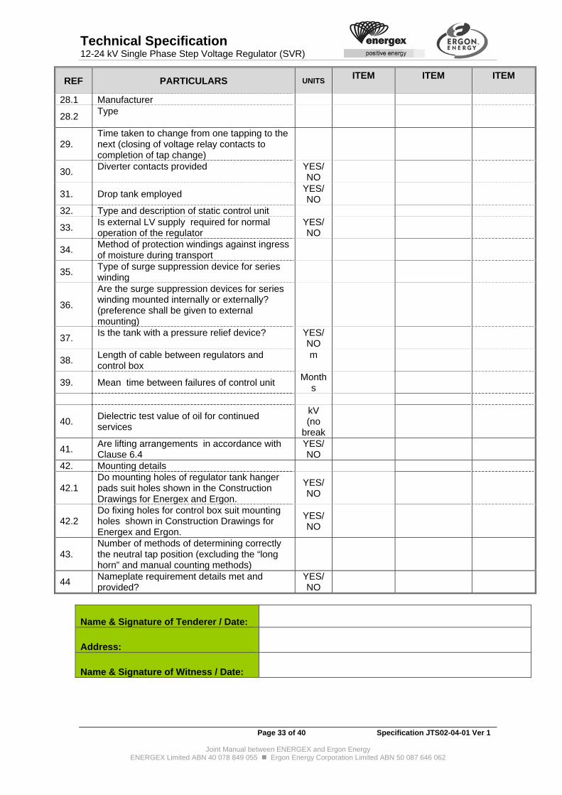
Technical Specification 12-24 kV Single Phase Step Voltage Regulator (SVR)
Page 33 of 40 Specification JTS02-04-01 Ver 1
Joint Manual between ENERGEX and Ergon Energy ENERGEX Limited ABN 40 078 849 055 Ergon Energy Corporation Limited ABN 50 087 646 062
REF PARTICULARS UNITS ITEM
ITEM
ITEM
28.1 Manufacturer
28.2 Type
29. Time taken to change from one tapping to the next (closing of voltage relay contacts to completion of tap change)
30. Diverter contacts provided
YES/NO
31. Drop tank employed YES/NO
32. Type and description of static control unit
33. Is external LV supply required for normal operation of the regulator
YES/NO
34. Method of protection windings against ingress of moisture during transport
35. Type of surge suppression device for series winding
36.
Are the surge suppression devices for series winding mounted internally or externally? (preference shall be given to external mounting)
37. Is the tank with a pressure relief device?
YES/NO
38. Length of cable between regulators and control box
m
39. Mean time between failures of control unit Month
s
40. Dielectric test value of oil for continued services
kV (no
break
41. Are lifting arrangements in accordance with Clause 6.4
YES/NO
42. Mounting details
42.1 Do mounting holes of regulator tank hanger pads suit holes shown in the Construction Drawings for Energex and Ergon.
YES/NO
42.2 Do fixing holes for control box suit mounting holes shown in Construction Drawings for Energex and Ergon.
YES/NO
43. Number of methods of determining correctly the neutral tap position (excluding the “long horn” and manual counting methods)
44 Nameplate requirement details met and provided?
YES/NO
Name & Signature of Tenderer / Date:
Address:
Name & Signature of Witness / Date:
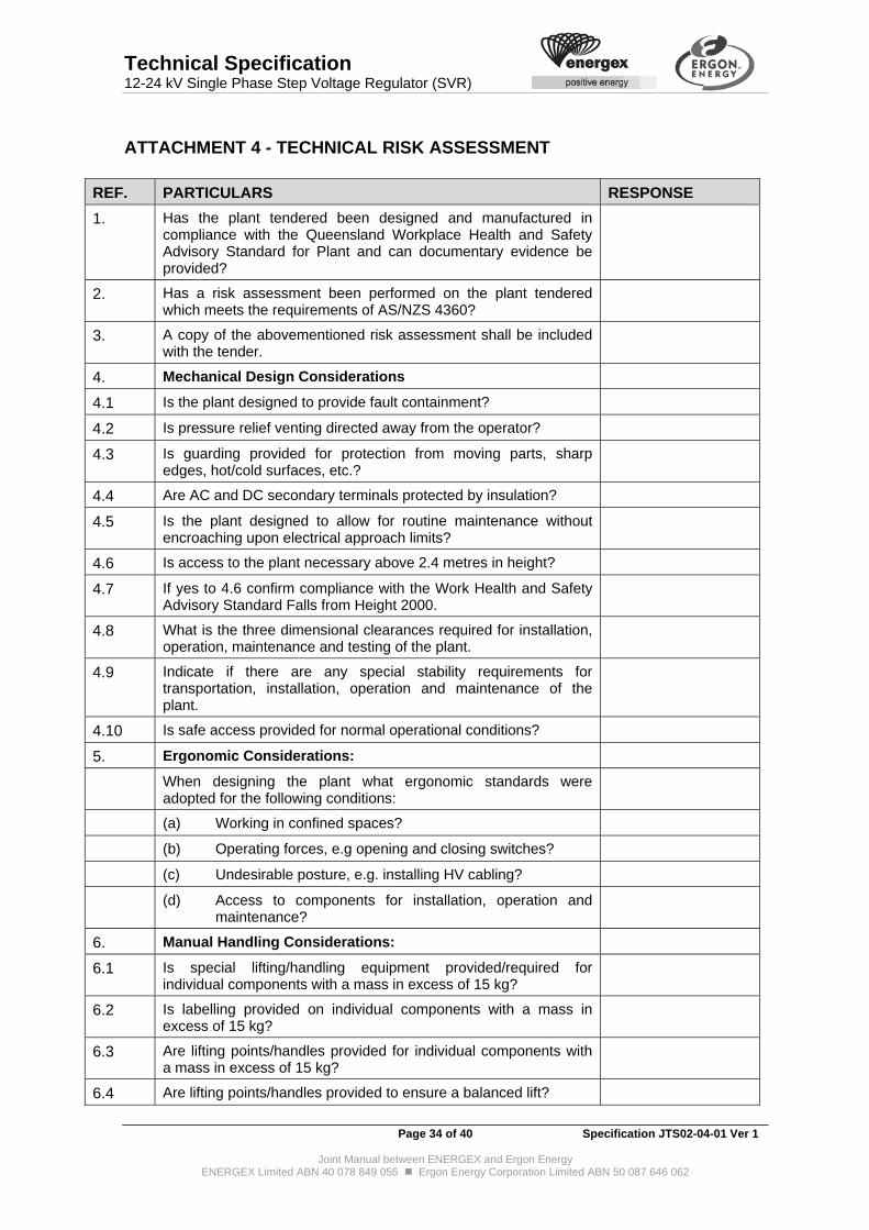
Technical Specification 12-24 kV Single Phase Step Voltage Regulator (SVR)
Page 34 of 40 Specification JTS02-04-01 Ver 1
Joint Manual between ENERGEX and Ergon Energy ENERGEX Limited ABN 40 078 849 055 Ergon Energy Corporation Limited ABN 50 087 646 062
ATTACHMENT 4 - TECHNICAL RISK ASSESSMENT
REF. PARTICULARS RESPONSE
1. Has the plant tendered been designed and manufactured in compliance with the Queensland Workplace Health and Safety Advisory Standard for Plant and can documentary evidence be provided?
2. Has a risk assessment been performed on the plant tendered which meets the requirements of AS/NZS 4360?
3. A copy of the abovementioned risk assessment shall be included with the tender.
4. Mechanical Design Considerations
4.1 Is the plant designed to provide fault containment?
4.2 Is pressure relief venting directed away from the operator?
4.3 Is guarding provided for protection from moving parts, sharp edges, hot/cold surfaces, etc.?
4.4 Are AC and DC secondary terminals protected by insulation?
4.5 Is the plant designed to allow for routine maintenance without encroaching upon electrical approach limits?
4.6 Is access to the plant necessary above 2.4 metres in height?
4.7 If yes to 4.6 confirm compliance with the Work Health and Safety Advisory Standard Falls from Height 2000.
4.8 What is the three dimensional clearances required for installation, operation, maintenance and testing of the plant.
4.9 Indicate if there are any special stability requirements for transportation, installation, operation and maintenance of the plant.
4.10 Is safe access provided for normal operational conditions?
5. Ergonomic Considerations:
When designing the plant what ergonomic standards were adopted for the following conditions:
(a) Working in confined spaces?
(b) Operating forces, e.g opening and closing switches?
(c) Undesirable posture, e.g. installing HV cabling?
(d) Access to components for installation, operation and maintenance?
6. Manual Handling Considerations:
6.1 Is special lifting/handling equipment provided/required for individual components with a mass in excess of 15 kg?
6.2 Is labelling provided on individual components with a mass in excess of 15 kg?
6.3 Are lifting points/handles provided for individual components with a mass in excess of 15 kg?
6.4 Are lifting points/handles provided to ensure a balanced lift?
Technical Specification 12-24 kV Single Phase Step Voltage Regulator (SVR)
Page 35 of 40 Specification JTS02-04-01 Ver 1
Joint Manual between ENERGEX and Ergon Energy ENERGEX Limited ABN 40 078 849 055 Ergon Energy Corporation Limited ABN 50 087 646 062
REF. PARTICULARS RESPONSE
7. Hazardous Substance Considerations:
7.1 What hazardous substances are used/produced (including after failure) such as:
(a) Insulating mediums, e.g. oils, etc.
(b) Gas, e.g. SF6, Halogen, etc.
(c) Other
7.2 Are normal hazardous substance controls compatible with operational requirements?
7.3 Is a Material Safety Data Sheet available for all hazardous substances contained within the plant?
7.4 What are the expected hazardous substance changes/by products associated with the deterioration of a substance?
7.5 What are the hazards associated with handling hazardous substances after plant failure?
8. Environmental Considerations:
8.1 Does the plant contain components which could cause an environmental hazard should plant failure occur?
8.2 If yes to 8.1 please list these components
8.3 Can the tenderer demonstrate that the plant is designed to limit the extent of environmental hazard should plant failure occur?
9. Do all symbols and labels provided on the plant conform to the requirements of the Queensland Workplace Health and Safety Advisory Standard for Plant?
10. What hazards, if any, are created should the plant be left in short or long term storage?
11. Indicate if special training, unique for this plant, is required.
12. For plant supplied with pressure vessels containing gas, etc. is clear indication given about the contents and pressure of such vessels.
13. Is the plant supplied with any stored energy components, e.g. charged springs?
14. If yes to 13, are these components clearly identified? Name & Signature of Tenderer / Date:
Address:
Name & Signature of Witness / Date:
Technical Specification 12-24 kV Single Phase Step Voltage Regulator (SVR)
Page 36 of 40 Specification JTS02-04-01 Ver 1
Joint Manual between ENERGEX and Ergon Energy ENERGEX Limited ABN 40 078 849 055 Ergon Energy Corporation Limited ABN 50 087 646 062
12. ATTACHMENT 5 – COMMENTS ON PRODUCT RELIABILITY Please provide comments regarding reliability of the product offered and provide evidence to substantiate the claims.
Name & Signature of Tenderer / Date:
Address:
Name & Signature of Witness / Date:

Technical Specification 12-24 kV Single Phase Step Voltage Regulator (SVR)
Page 37 of 40 Specification JTS02-04-01 Ver 1
Joint Manual between ENERGEX and Ergon Energy ENERGEX Limited ABN 40 078 849 055 Ergon Energy Corporation Limited ABN 50 087 646 062
ATTACHMENT 6 - RATING PLATE DETAILS
Attachment 6A - Rating Plate Details for the SVR - Energex The successful Tenderer shall complete the spreadsheet provided by the Purchaser as per the format below and return to the Purchaser with the first delivery of the plant item under contract or as requested by the Purchaser.
PLANT TECHNICAL DATA
STOCK CODE
Attribute ID Attribute Description VS Example Units Val Obj
BASE-KVA Base kVA Impedances are calculated upon S 200 kVA KVA-BASE
CONTROL-BOX Type of control unit D -
COOLNG-INSULNT-TYPE
Type of cooling/insulation medium S OIL
-
INSUL-MEDIUM
INSUL-MASS-VOL Mass SF6 gas - Oil volume S 2.6 Kg/Litre
DMS-TRMNL-CT No of Recognised Terminals S 2 Count TRMNL-CT
LOAD-LOSS-PRNCPL-TAP
Full load loss on principle tap – Cu losses S 1.325 kW
IMPED-MAX-TAP Impedance on max tap S 4.0 %
IMPED-MIN-TAP Impedance on min tap S 3.2 %
IMPED-PRNCPL-TAP Impedance on principle tap S 3.6 %
MAG-A-100PC Excitation Current at 100% load S 0.25 A
MANUFR-TYPE Manufacturer’s type S
NO-LOAD-LOSS-PRNCPL-TAP
No load loss on principle tap – Fe losses S 0.6 kW
PHASE Number of Phases S 1 Count PHASE-COUNT
RATED-VLTGE Maximum voltage rating S 12000 V VLTGE-RATED
TAPCHG-MANUFR Tapchanger manufacturer S -
TAPCHG-MAX-OPS Maximum number of Tapchanger Operations S 2,000,000 Count
TAPCHG-NO-OF-TAPS Number of taps S 32 Count
TAPCHG-RANGE-BOTTOM
Tapchanger Range Bottom (Boost) S -10 %

Technical Specification 12-24 kV Single Phase Step Voltage Regulator (SVR)
Page 38 of 40 Specification JTS02-04-01 Ver 1
Joint Manual between ENERGEX and Ergon Energy ENERGEX Limited ABN 40 078 849 055 Ergon Energy Corporation Limited ABN 50 087 646 062
PLANT TECHNICAL DATA
STOCK CODE
Attribute ID Attribute Description VS Example Units Val Obj
TAPCHG-RANGE-TOP Tapchanger Range Top (Buck) S 10 %
TAPCHG-RATING Rating of tapchanger S 350 kVA
TAPCHG-SERIAL-NO Tapchanger serial number AS 49336 -
TAPCHG-STEP-SZ Tapchanger step size S 0.625 %
TAPCHG-TYPE Tapchanger type or model S 928C -
WINDNG-CONFIG Winding arrangement S - VECTOR-
GRP
Energex will also require a running summary of all deliveries cross referencing the Energex Plant ID, SVR Serial Number, Control Box Serial Number, despatch date and manufactured date in the form of an excel spreadsheet via email (template as shown below) to [email protected]
Single Phase Step Voltage Regulators (SVRs)
SC_____________ Manufacturer _________________
Energex Plant ID
SVR Serial Number
Control Box Serial Number
Despatch Date Manufactured Date
Please note that the email addresses will be confirmed by the Purchaser at the time of contract negotiation.

Technical Specification 12-24 kV Single Phase Step Voltage Regulator (SVR)
Page 39 of 40 Specification JTS02-04-01 Ver 1
Joint Manual between ENERGEX and Ergon Energy ENERGEX Limited ABN 40 078 849 055 Ergon Energy Corporation Limited ABN 50 087 646 062
Attachment 6B - Rating Plate Details for the SVR – Ergon The successful Tenderer shall complete the spreadsheet provided by the Purchaser as per the format below and return to the Purchaser by electronic mail to: [email protected] with each delivery as applicable. Please note that the schedule provided will be confirmed at the time of contract negotiation. TEMPLATE FOR SINGLE PHASE STEP VOLTAGE REGULATOR (SVR)
SPN STRUCTURED PLANT NUMBER
CONTRACT-NO CONTRACT NO
MAKE-TX MANUFACTURER OF THE TX
MASS-TOTAL TOTAL WEIGHT (KG) MODEL MODEL NO PHASE-NO NUMBER OF PHASES SERIAL_NUMBER SERIAL NUMBER
TX-HV-MAX-A TX HV MAX CURRENT (A)
TX-TAP-NO NUMBER OF TAPS IN TX
TX-TAP-RANGE TAPPING RANGE FOR TX TAP RANGE
VOLT-PRI-KV PRIMARY VOLTAGE (KV)
YOM YEAR OF MANUFACTURE
CONTROL BOX TYPE OF CONTROL UNIT
CONTROL BOX SERIAL NUMBER

Technical Specification 12-24 kV Single Phase Step Voltage Regulator (SVR)
Page 40 of 40 Specification JTS02-04-01 Ver 1
Joint Manual between ENERGEX and Ergon Energy ENERGEX Limited ABN 40 078 849 055 Ergon Energy Corporation Limited ABN 50 087 646 062
ATTACHMENT 7 - TECHNICAL DOCUMENTATION CHECKLIST * Please complete the technical documentation checklist below and provide remarks as applicable.
Clause Ref Particulars *Specified Response (Yes or No)
Technical Requirements Schedule of Technical Clauses Compliance
Completion of the Schedule of Technical Clauses Compliance. Please submit both electronic (excel spreadsheet) and hard-copy with signature.
5.1 Comments on Design and service life of the product provided? 4 Suitability to the Purchaser's Network 5.1.9 Conformance with Firmware Revisions Requirement 6.3.2 Compliance with Plant number marked on the regulator's tank 6.12 Surge Arrester Mounting Bracket Details provided? 6.13 Compliance with Nameplate Requirements 6.14 Details of the optional bio-degradable insulation oil 6.15 & Error! Reference source not found.
Compliance with optional SVR construction material requirement using Stainless Steel for all items. Details provided.
6.9 Compliance with the Regulator Pole Mounting Requirements. Please provide details including drawings.
10.7 Test Certificates provided? 11.3 Completion of Risk Assessment 11.8 Availability of samples and delivery time 11.10 Drawings and Information to be submitted by the Tenderer? Are the
documents requested by the Purchaser submitted? Particular attention is drawn to the product manuals.
Attachment 1 Compliance with Specific Technical Requirement? Attachment 2 Details provided? Attachment 3 Details provided? Attachment 4 Details provided? Attachment 5 Details provided? Attachment 6 Requirements noted and details provided? Attachment 7 The Tenderer shall note the Rating Plate details as stipulated in the
Attachment.
Annexure A Details provided? Technical Schedule completed? All clauses applicable
Completion of Technical Departures. Please state the non-compliance to any of the clauses stated within this Technical Specification and remarks as appropriate.
As applicable Any further information to form part of Tender Submission? If so, please briefly provide a list.
General Requirements 11.1 Special tools, gauges or accessories 11.2 Quality Assurance system certification 11.5 Environmental Consideration 11.6 Reliability of the equipment. 11.7 Traceability 11.9 Training materials As applicable Any further information to form part of Tender Submission? If so, please
briefly provide a list.

1
ANNEXURE A
SCADA AND AUTOMATION REQUIREMENTS
FOR SINGLE PHASE STEP VOLTAGE REGULATOR (SVR)

2
Annexure A – SCADA and Automation 1. INTRODUCTION 1.1. This document outlines the purchaser’s requirements for SCADA and automation to be
provided by tenderers for single-phase Step Voltage Regulators (SVRs).
1.2. Information security is an increasing concern in an era of software-based functions and shared communications media built to open standards. In the remainder of this document, the term “security architecture” refers to the design and implementation of security measures such as
Physical security,
Management/updating of security credentials such as passwords and keys,
User-to-machine, machine-to-machine and machine-to-communications-network authentication,
Role-based control of access to functions and data,
Encryption of data on communications media,
Non-repudiation,
Apportionment of bandwidth between real-time and non-real-time functions on shared communications media,
Failure detection, failsafe operation and recovery mechanisms,
Auditing of firmware and configuration,
Logging of access, e.g. time, date, by whom and for what purpose.
2. GENERAL REQUIREMENTS 2.1. The RTU/controller and regulator shall be parts of an integrated SVR design. The local
and remote control functions shall be seamlessly integrated. 3. HARDWARE, SOFTWARE AND FIRMWARE 3.1. The Supplier shall have formal change control procedures for its hardware, software and
firmware. Such procedures shall maintain a complete revision history and allow the full revision details of any delivered RTU/controller to be provided on demand.
3.2. For the duration of the contract, the purchaser shall not be supplied with changes or
upgrades to hardware, software or firmware without its explicit permission. 3.3. Protocols for the notification and escalation of hardware, software or firmware problems
and the testing and application of associated fixes shall be agreed by the purchaser and the supplier prior to the commencement of the contract.
3.4. The Supplier shall indemnify the Purchaser against the deployment costs of hardware,
software and firmware upgrades, should they be necessary for any reason other than purchaser-requested or purchaser-approved enhancements.
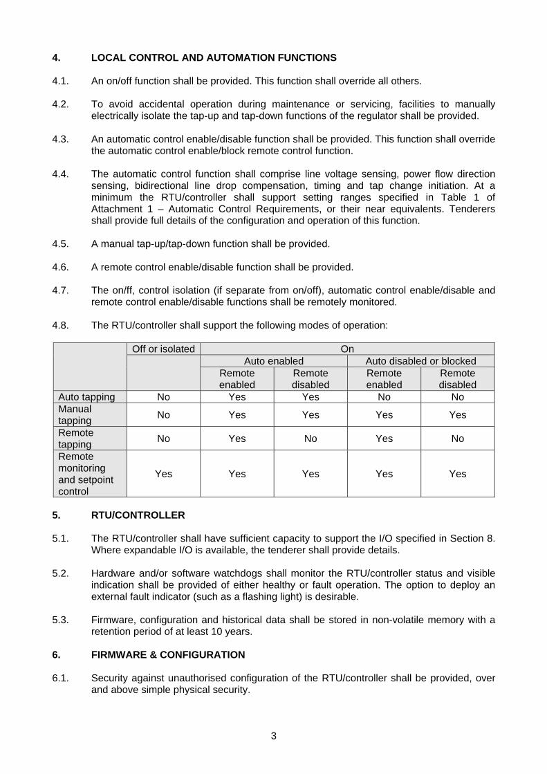
3
4. LOCAL CONTROL AND AUTOMATION FUNCTIONS 4.1. An on/off function shall be provided. This function shall override all others. 4.2. To avoid accidental operation during maintenance or servicing, facilities to manually
electrically isolate the tap-up and tap-down functions of the regulator shall be provided. 4.3. An automatic control enable/disable function shall be provided. This function shall override
the automatic control enable/block remote control function. 4.4. The automatic control function shall comprise line voltage sensing, power flow direction
sensing, bidirectional line drop compensation, timing and tap change initiation. At a minimum the RTU/controller shall support setting ranges specified in Table 1 of Attachment 1 – Automatic Control Requirements, or their near equivalents. Tenderers shall provide full details of the configuration and operation of this function.
4.5. A manual tap-up/tap-down function shall be provided. 4.6. A remote control enable/disable function shall be provided. 4.7. The on/ff, control isolation (if separate from on/off), automatic control enable/disable and
remote control enable/disable functions shall be remotely monitored. 4.8. The RTU/controller shall support the following modes of operation:
Off or isolated On
Auto enabled Auto disabled or blocked
Remote enabled
Remote disabled
Remote enabled
Remote disabled
Auto tapping No Yes Yes No No Manual tapping
No Yes Yes Yes Yes
Remote tapping
No Yes No Yes No
Remote monitoring and setpoint control
Yes Yes Yes Yes Yes
5. RTU/CONTROLLER 5.1. The RTU/controller shall have sufficient capacity to support the I/O specified in Section 8.
Where expandable I/O is available, the tenderer shall provide details. 5.2. Hardware and/or software watchdogs shall monitor the RTU/controller status and visible
indication shall be provided of either healthy or fault operation. The option to deploy an external fault indicator (such as a flashing light) is desirable.
5.3. Firmware, configuration and historical data shall be stored in non-volatile memory with a
retention period of at least 10 years. 6. FIRMWARE & CONFIGURATION 6.1. Security against unauthorised configuration of the RTU/controller shall be provided, over
and above simple physical security.

4
6.2. The local user interface of the RTU/controller should be capable of displaying the version numbers and free-text descriptions of the currently active hardware, firmware and configuration(s) and should immediately refresh this information upon updating of any/all of these components.
6.3. Tenderers shall provide details of RTU/controller firmware and configuration and include
information on
The security architecture, including levels of user access that can be configured by a system administrator,
Local user interfaces,
Communications interfaces,
The ability to accept configuration datasets and firmware from external (PC-based or centralised) management software,
The ability to accept configuration subsets for different functions such as communications, SCADA, automation and protection,
The ability to accept multiple, successive configuration changes in advance of their requirement, and selectively activate them when required ,
The ability to revert to earlier versions of configuration datasets and the capacity of the system to retain earlier versions of the datasets,
The ability to automatically enforce configuration dataset version-compatibility with the underlying firmware,
The ability to automatically enforce firmware (operating system and/or application) version compatibility with the underlying platform,
The ability to keep a log of changes to configuration datasets including date, time, user identification and a free text field to describe the change,
The ability to provide hardware, firmware, and configuration version information as well as configuration datasets, diagnostic logs, historical analog and event data to external (PC-based or centralised) management software.
6.4. Configuration datasets and firmware shall be transferable to and from the RTU/controller
via a laptop PC. Tenderers shall describe
The type of interface and if serial, how the phasing out of serial ports by PC manufacturers will be accommodated, and
Any hardware or software constraints on interfacing laptops that might affect their procurement.
6.5. Tenderers shall provide details of the application software used to manage the
RTU/controller, and include information on
The required operating environment and the Tenderer’s plans to accommodate future operating environments,
The security architecture, including levels of user access that can be configured by a system administrator,
The availability of an intuitive, graphical user interface,

5
The ability to transfer configuration datasets and firmware to and from the RTU/controller,
The ability to separately apply configuration subsets for different functions such as communications, SCADA, automation and protection,
The ability to transfer multiple, successive configuration changes in advance of their requirement, and selectively activate them when required,
The ability instigate reversion to earlier versions of configuration datasets,
The ability to upload and display hardware, firmware, and configuration version information as well as configuration datasets, diagnostic logs, historical analog and event data, and export such data in common formats such as CSV, XLS, XML, COMTRADE and COMFEDE,
The ability to act as a console for online diagnostic and administrative functions.
6.6. There is a strong preference for the ability to remotely manage the RTU/controller via the
SCADA communications network. Tenderers shall provide details on
Whether such functionality is offered,
What superset or subset of the functions listed in section 6.5 is supported,
How the functions are securely undertaken within the communications network proposed (refer section 7),
Whether the functions can be remotely exercised by the management software described in section 6.5. If so, how this software is designed to integrate with the SCADA communications network,
Whether the functions can be remotely exercised by enterprise systems via a middleware interface such as SOAP/XML. If so, details of the software which implements the interface, and of how this software is designed to integrate with the SCADA communications network.
An example of a realistic configuration dataset size, based on the details provided herein, together with estimated transfer time to the RTU/controller over a 2400 baud link should be provided.
6.7. Tenderers shall describe the measures used during firmware upgrades to prevent an
unrecoverable loss off functionality. Indicative requirements can be found in NEMA Meter Upgradability Standard: SG-AMI 1-2009.
6.8. Tenderers shall provide details of the application software used to prepare configuration
datasets and include information on
The required operating environment and the Tenderer’s plans to accommodate future operating environments,
The security architecture, including levels of user access that can be configured by a system administrator,
The availability of an intuitive, graphical user interface,
The ability to prepare separate configuration subsets for different functional domains such as communications, SCADA, automation and protection,
The ability to prepare multiple, successive configuration changes in advance of their requirement,
6
Whether configuration datasets can be prepared expeditiously using user-defined templates rather than starting from scratch for each new SVR,
Whether the software can import data in common formats such as CSV, XLS and XML in order to instantiate and populate templates automatically,
Whether the software can import data in common formats such as CSV, XLS and XML, in order to import complete configuration datasets that have been created by an external application,
Whether the software can export configuration datasets in common formats such as CSV, XLS and XML,
Whether the software can be integrated with enterprise systems via a middleware interface such as SOAP/XML.
6.9. Tenderers shall provide details of the structure of the configuration data, as used for
import, export and transfer.
There is a strong preference for an XML-based structure with an accompanying XML schema definition incorporating schema version information.
The structure should include a user-supplied free-text version description which can be displayed on the local user interface of the RTU/controller.
7. COMMUNICATIONS 7.1. At least two independent RS-232 or one RS-232 and one USB communication ports that
allow for simultaneous operation shall be provided and shall be used as follows:
For engineering functions (e.g. diagnostic, configuration and programming) from a personal computer via RS-232 or USB.
To interface to remote SCADA communications equipment (e.g. modem or radio) via RS-232.
7.2. The RS232 ports shall be configurable over the full range between 1200 - 9600bps.
Tenderers should indicate whether higher speeds are supported. 7.3. The RS-232 ports shall support full asynchronous V.24 functionality. 7.4. Tenderers shall indicate whether the two RS232 ports can be configured as RS485 ports
to offer extended range multidrop communications. Tenderers shall provide details. 7.5. Energex generally applies SVRs in pairs for three-phase voltage regulation by adjustment
of two phase-phase voltages. Tenderers shall indicate whether the communications can be configured for multi-drop operation enabling remote control and monitoring of both SVRs with a single radio or modem. Tenderers shall provide details.
7.6. Equipment shall communicate using the DNP3 communications protocol. The minimum
requirements for DNP3 are:
The protocol shall be DNP3 compliant to a minimum of level 2.
DNP3 objects for setting analog deadbands shall be supported.
The slave device shall support the sending of unsolicited responses.

7
The implementation shall comply with the latest DNP3 IED Certification Procedures.
The points list shall be configurable such that only the desired points can be selected for monitoring with flexibility to number them consecutively from point 0.
7.7. Extended datasets such as hardware, firmware, and configuration version information, configuration datasets, diagnostic logs, security logs, oscillograms, analog historical logs and digital event logs should be accessible via a standard DNP3 mechanism.
7.8. Tenderers shall supply a DNP3 Device Profile explaining the message and command
structure, to allow the Purchaser to assess the compatibility of the RTU/controller with its existing SCADA system.
7.9. Tenderers should provide any evidence of DNP3 conformance testing that has been
carried out. 7.10. Although not a requirement, the purchaser is interested in the option of supporting
redundant communication links to improve reliability and reduce risk. Tenderers should indicate whether the RTU/controller can support two DNP3 ports (RS-232) such that each is independently configurable to allow the configuration of primary and backup communications together with a failover algorithm to transfer DNP3 communications to the backup port (or vice versa) automatically and in response to appropriate local or remote controls. Such a feature shall not restrict the utilisation of the second port for engineering functions.
7.11. The RTU/controller should be equipped for IP-based communications. The minimum
requirement for IP-based communications is as follows:
IPv4
10/100/1000-baseT (RJ45) connection, and/or serial (ITU-T V.24) connection at a minimum speed of 9 600 bits per second (asynchronous)
Static and DHCP/PPP (as appropriate) IP configuration
DNP3 in TCP and DNP3 in UDP complying with the dnp.org specification
Other network protocol support – TFTP, ICMP (ping), FTP and NTP
Telnet and/or TCP socket and/or HTTP/HTML access to management services
TFTP and/or FTP and/or HTTP download and upload of firmware and configuration datasets
TFTP and/or FTP and/or HTTP upload of historical analog and event data
Compatible management/remote management software for Windows and/or Linux
7.12. Additional, strongly preferred features of IP-based communications include:
Secure versions of Telnet, FTP, TCP sockets and HTTP, viz. SSH, SFTP, SSL/TLS and HTTPS
Ability to define standard DSCP markings for logical groupings of traffic types (e.g. controls and management)
DNP3 secure authentication complying with the dnp.org specification
Time synchronisation via (S)NTP or IEEE 1588v2
8
7.13. Additional, desirable features of IP-based communications include:
IPv6
Stateless auto-configuration and/or DHCPv6
Redundancy / failover mechanism (Clause 7.10) extended to include IP-based SCADA communications
SNMPv3 management with free vendor-supplied MIBs
Terminal server for additional serial ports
Ability to route IP traffic via additional 10/100/1000-baseT or serial PPP ports
8. SCADA I/O 8.1. At a minimum the RTU/controller shall support all DNP3 points specified in Table 2 of
Attachment 2 – SCADA I/O Requirements, or their functional equivalents. 8.2. A comprehensive list of DNP3 I/O points supported by the RTU/controller shall be
provided. 8.3. Tenderers shall describe the capability of the RTU/controller to capture and store
cumulative data such as averaged voltage(s), current, real power, reactive power and harmonics, also event-based data such as maxima, minima, sags, surges, spikes, oscillograms and digital events.
8.4. Data will be time stamped to a resolution of 10ms or better. 8.5. The minimum requirements for cumulative and event-based data storage are three
months of 15 minute average voltage(s) and current, 1000 events, maximum and minimum voltage(s) since last reset, and maximum and minimum tap position since last reset. Local display and resetting functions shall be provided.
8.6. Units when configured for bidirectional regulation shall store data for the forward and
reverse power flow directions separately. 8.7. Contact Wear Monitor: A desirable feature is a tapchanger contact wear monitor to
provide information that can be used to plan the maintenance for the equipment. It should be based on an algorithm that at least incorporates the number of operations and the interrupted current. Tenderers shall advise whether such facilities are offered and provide details including means of resetting after maintenance.
8.8. Any contact wear monitor should provide a remotely monitored alarm configurable by the
user at an appropriate setpoint and analog measures of wear. Tenderers shall advise what features are offered.
8.9. Analog Accuracy: Tenderers shall detail the accuracy of measured analog quantities with
particular attention to the following issues:
VT accuracy (%)
CT accuracy (%)
ADC conversion accuracy (%)
Digital resolution (no of bits)
9
Overall voltage accuracy (%)
Overall current accuracy (%)
8.10. Tenderers shall state whether the RTU/controller can synchronise time to an IRIG-B time
signal. Interface details shall be provided. 9. AUXILIARY POWER SUPPLY 9.1. The regulator shall provide an AC auxiliary supply capable of supporting all loads
including motors/actuators, environmental control devices, the RTU/controller and a radio or modem for SCADA communication.
9.2. The nominal voltage of the AC auxiliary supply for the radio or modem shall be in the
range 120-270Vac with a capacity of at least 15V.A peak, 5V.A average. Tenderers shall supply details.
9.3. The AC auxiliary supply for the radio or modem shall be on dedicated circuit with an
isolation switch and protective fuse and wired to customer-accessible terminals. 10. CONTROL CABINET 10.1. The control cabinet shall be made from 3CR12 or 316-grade stainless steel. 3CR12 shall
receive the same paint treatment as the regulator tank. 316-grade stainless steel may be left unpainted.
10.2. Access to the RTU/controller, control panel and power supply shall be by means of a
latchable, hinged door that can be locked with a padlock incorporating an 8.7mm diameter shackle.
10.3. All controls and indications shall be readily accessible by the operator when working from
any normal control position, including from a ladder against the pole. Any display shall be visible day and night – backlighting shall be provided as necessary.
10.4. All controls and indications shall be labelled/displayed in English so as to clearly indicate
their respective function and operation. Day-month-year formatting shall be used for dates.
10.5. The control cabinet shall be waterproof and sealed against access by ants or other
vermin. 10.6. Electronic equipment should be protected with IP65 integrity (against all dust and low
pressure jets) in accordance with AS60529. 10.7. Other control equipment should be protected with at least IP44 integrity (protection
against 1 mm objects and sprayed water) to AS60529 if cabinet ventilation is required and the equipment is not adversely affected.
10.8. Environmental control devices such as fans, heaters and dust filters will add significantly
to the lifecycle costs of the equipment. Such devices, if part of the design, must operate only as required (e.g. under thermostatic control) and must be self-monitoring. Tenderers shall list and describe these devices and the associated spare parts and consumables requirements.
10.9. Two complete sets of spare fuses used in the control cabinet shall be supplied, suitably
and safely stowed, with the control cabinet.

10
10.10. The Tenderer shall provide a nominated serial number corresponding with the
Purchaser’s SPN or Plant Number. The SPN or Plant Number will be nominated by the Purchaser at the time of order.
11. TEST EQUIPMENT 11.1. A test bench RTU/controller for the purpose of testing RTU/controller configurations in an
office environment shall be quoted as a separate option. It is anticipated that several such devices will be required to allow technicians to train, test configurations and fault find under laboratory conditions.
11.2. Test bench RTU/controllers should preferably accept a nominal 240Vac supply. If other
voltages are standard, then suitable 240Vac power supplies shall be included. 11.3. Test bench RTU/controllers should include facilities to allow full simulation of the
regulators to which they may be mated, in order to allow configuration functionality to be tested as far as practicable. Tenderers shall provide full details of the test equipment offered, and specifically listing any included and excluded features described here.
11.4. The test bench RTU/controller shall be functionally identical in all key aspects to the
tendered equipment, particularly with respect to the local user interface, communications protocols and laptop interfacing software.
11.5. Suitable equipment to allow simulation of the regulator for the purposes of in situ testing of
protection and operation functions as described in Sections 4 and 8 shall be offered as an option. Whether this equipment is also required to supplement the test bench RTU/controller shall be clarified by the Tenderer.
12. PERFORMANCE AND TESTING 12.1. Type Test Compliance
12.1.1. All Equipment offered shall be fully Type Tested as required by the relevant Australian and/or International Standards at the time of tendering and Type Test Certificates complete with supplementary documentation shall be included with the tender regardless of whether such equipment has previously been supplied to the Purchaser.
12.1.2. Where the equipment offered is Type Tested to Standards other than those specified in this technical specification, full details of these Standards are to be provided at the time of tendering.
12.1.3. Where equipment is offered of a similar design to that previously tested, consideration may be given to accepting previous Type Test Certificates if they are submitted with a detailed engineering evaluation substantiating why they should be accepted. Such an evaluation shall provide all relevant details so that the Purchaser can establish the validity of existing Type Tests.
12.1.4. Where company names have changed since the submitted Type Test Certificates were originally issued, the name change details shall be detailed in the tender submission for every change up to the tender date.
11
12.1.5. Type Tests should be certified by a laboratory accredited by an Accreditation Entity, such as the National Association of Testing Authorities, Australia (NATA), that is a signatory to the International Laboratory Accreditation Cooperation Mutual Recognition Arrangement (ILAC MRA). Full accreditation details of the Type Testing laboratory and the certifying Accreditation Entity shall be provided by the Tenderer.
12.1.6. Where Type Tests are performed in unaccredited laboratories or supplier facilities, the tests shall be witnessed by an independent or Purchaser-endorsed witness. Where applicable, details of the independent witness shall be provided with the Tender. Such Type Test reports shall be to the same standard as expected from an independent accredited laboratory.
12.2. Routine Tests
12.2.1. All Equipment shall be Routine Tested in accordance with the relevant Australian and/or International Standards.
12.2.2. Where the equipment offered will be Routine Tested to Standards other than those specified in this technical specification, full details of these Standards are to be provided at the time of tendering.
12.3. Acceptance Tests
12.3.1. The purchaser may carry out acceptance tests on equipment to prove it conforms to the requirements of this Technical Specification. Any equipment showing evidence of failure to comply with the requirements of this specification will be liable to rejection.
12.4. Witnessing of Tests
12.4.1. The purchaser reserves the right to witness all testing.
12.4.2. The Supplier shall give the purchaser reasonable notice of when testing will be carried out and if requested, shall provide appropriate test plans with the notice.
12.5. Test Certificates
12.5.1. All test certificates shall include the manufacturer’s serial number(s) and upon allocation; the purchaser’s order number, contract/item number and specification number.
13. ELECTROMAGNETIC COMPLIANCE 13.1. Electromagnetic Compliance with respect to both emissions and immunity is an area of
growing concern due to the proliferation of electronic equipment such as mobile phones, GPSs, mobile computing equipment and PDAs. Any supplied equipment shall have high immunity to radio frequency emissions, magnetic fields, electrostatic discharge, fast transients, voltage surges, voltage sags and voltage interruptions as defined in the AS 61000 series of Standards.
13.2. Tenderers shall list which of the AS 61000 series of immunity standards have been tested
against, or provide details of other equivalent testing carried out including referenced standards. The equipment performance should be classified according to one of the

12
following categories for each of the immunity tests. Equipment offering higher immunity levels will be favoured.
Normal performance as per equipment specifications
Temporary loss of function or degradation of performance which ceases after the disturbance ceases and from which the equipment under test recovers its normal performance without human intervention
Temporary loss of function or degradation of performance, the correction of which requires operator intervention
Loss of function or degradation of performance which is not recoverable due to damage due to hardware failure, data corruption or other causes.
13.3. The Australian Communications and Media Authority has introduced the Electromagnetic
Compatibility (EMC) regulatory arrangements under the Radio Communications Act 1992. The purpose of the regulation is to minimise electromagnetic interference between electronic products. Suppliers shall ensure that equipment that falls within the scope of the regulation complies with the requirements and is appropriately labelled (i.e. “C-Tick” and a unique supplier identification).
14. RELIABILITY 14.1. Tenderers shall state the reliability of the equipment and the performance of the materials
offered during its service life under the specified system and environmental conditions. 14.2. Such statements shall include evidence in support of the reliability and performance
claimed including a Failure Mode and Effect Analysis. Any FMEA analysis should include the identification of all system components, identification of all system functions and a description of how components are combined to realise those functions. The failure modes and failure rates for each component of each system function should be assessed. Component failure rate data should be sourced from in service performance, MIL-HDBK-217F calculations or otherwise derived with supporting justification from similar equipment.
15. MAINTENANCE 15.1. Tenderers shall indicate the frequency and degree of maintenance required for the
RTU/controller. 16. SPARES 16.1. Tenderers shall provide a priced list of all the smallest user replaceable component (line
replaceable unit or LRU) of the offered equipment and any accessories. This may include such items as:
Electronics modules,
Cables.
16.2. Tenderers shall provide a recommendation as to the quantity of spares that should be
held by the Purchaser based on anticipated equipment order quantities, component failure rates and the Tenderer’s policy of holding spares in stock.
16.3. It is critical to the Purchaser that equipment can be operated and maintained for several
decades. Given that microelectronics technology is rapidly evolving it is imperative

13
therefore that installed regulators do not become incompatible with later developments. Tenderers should advise whether they have any internally approved plans to ensure that new RTU/controllers are backwardly compatible with existing units and can therefore be retrofitted to installed regulators without loss of functionality. Relevant excerpts of such documents should be provided where possible.
16.4. There is a reasonable probability that the regulator life could be limited by the
RTU/controller. If for whatever reason, the Supplier were to cease or change its operations such that RTU/controllers were no longer available or compatible, it would be beneficial to the Purchaser if 3rd party RTU/controllers could be fitted. Tenderers should advise what information they would be prepared to supply about the regulator/controller interface to facilitate such remedial action.
17. SUPPORT SOFTWARE 17.1. Tenderers shall list all application software required to support the deployment of the
offered equipment and included in the Tender price. This shall include any laptop software required to configure the RTU/controller, transfer firmware or otherwise communicate with the equipment.
17.2. Tenderers shall detail the minimum hardware and operating system requirements
necessary to support the application software. 17.3. Any application software should be available for multiple use and any software End Use
Licensing Agreement (EULA) should reflect this. If multiple use is not an option due to third party licensing or other constraints, Tenderers shall clearly identify this limitation and provide pricing for additional copies.
18. SAMPLES 18.1. Tenderers may be required to submit a sample RTU/controller of the type offered for the
Purchaser’s evaluation. Such samples should be functionally identical in all key aspects to the tendered equipment, particularly with respect to the local user interface, communications protocols and support software.
18.2. Samples shall be delivered freight free, suitably crated and packaged and labelled with
the following information:
Name of Tenderer and this Contract No
Contract Item Numbers
Supporting data on features and characteristics
18.3. The Purchaser shall at its discretion, either purchase the items at the tender price or
return the samples to the respective Tenderer after the contract has been awarded. Property remains with the Tenderer until the items are purchased.
18.4. The purchaser reserves the right to carry out integration testing with its SCADA and
automation systems, and to require the resolution of integration problems, prior to the commencement of the contract.
19. TRAINING 19.1. Training material in the form of drawings, instructions and/or audio visuals and sample
equipment shall be provided for the items accepted under the offer. The Tenderer shall
14
provide an optional price for the provision of training to the Purchaser’s staff and Contractors at a venue local to the Purchaser. Brief details of the training offered shall be provided in the tender documents. This material shall include but is not limited to the following topics:
Handling
Storage
Application (particularly in areas of heavy coastal pollution)
Installation
Maintenance
Operation
Environmental performance
Electrical performance
Mechanical performance
Disposal
Software
Commissioning
19.2. The Purchaser may require RTU/controllers for training, development and testing
purposes. These devices should be neatly packaged with one or more regulator simulators to enable realistic training, and the development and testing of RTU/controller configuration datasets, SCADA system software and the like.

15
ATTACHMENT 1 – AUTOMATIC CONTROL REQUIREMENTS Table 1 – Setting ranges required
SETTING PARAMETERS SETTING RANGE
PARAMETER UNITS LOW HIGH
Set Voltage (Forward) V 100 135 Bandwidth (Forward) V 1 6 Time Delay (Forward) sec 5 180 LDC, Resist (Forward) V -96 96 LDC, React (Forward) V -96 96 Regulator Configuration (note 1) - Note 1 Control Operating Mode (note 2) - Note 2 System Line Voltage V 1200 36000 Potential Tr Ratio - 10 300 Current Tr Prim Rating A 25 2000 Demand Time Interval min 3 60 Set Voltage (Reverse) V 100 135 Bandwidth (Reverse) V 1 6 Time Delay (Reverse) sec 5 180 LDC, Resist (Reverse) V -96 96 LDC, React (Reverse) V -96 96 Reverse Sensing Method - Note 3 Voltage Limiting Mode - Note 4 Vmin (Forward) V 120 135 Vmax (Forward) V 105 120 LDC Pmin (Forward) W Note 5 Rating LDC Pmax (Forward) W Note 5 Rating Vmin (Reverse) V 120 135 Vmax (Reverse) V 105 120 LDC Pmin (Reverse) W Note 5 Rating LDC Pmax (Reverse) W Note 5 Rating
Notes 1 Setting options required: Star, Delta Lagging or Delta Leading 2. Setting options required: Sequential (Standard), Time Integrating or Voltage Averaging 3. Setting options required: Locked Forward, Locked Reversed, Reversed Idle, Bidirectional, Neutral Idle,
Cogeneration, Reactive Bidirectional 4. Setting options required: Off, High limit active only or High & low limits active 5. The option to use a real-power-based LDC algorithm using the characteristic shown in Figure 1 is
desirable
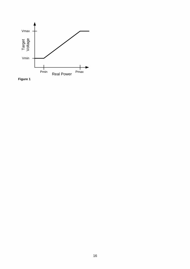
16
Real Power
Tar
get
V
olta
ge
Pmin Pmax
Vmin
Vmax
Figure 1

17
ATTACHMENT 2 – SCADA I/O REQUIREMENTS Table 2 –DNP3 point set required
POINT TYPE DESCRIPTION
DIGITAL At Neutral Tap
Reverse Power Flow
Control Off
Control Isolated (if separate from Control Off)
Automatic Control Disabled (locally)
Automatic Control Blocked (remotely)
Remote Control Disabled
Regulator Alarm
Controller Alarm
ANALOGUE Primary Load Voltage
Secondary Compensated Voltage
Primary Load Current
Calculated Source Voltage
Tap Position
Percent Regulation
Regulator Error Code
Controller Error Code
CONTROL Lower Tap
Raise Tap
Go to Neutral Tap
Enable/Block Automatic Control (latched)

18
ATTACHMENT 3 – TECHNICAL DETAILS Note: Where the Unit is “Described” and the tenderer offers a conforming tender, the response must include a reference to the relevant product documentation including the relevant section number or page number. If the tenderer does not offer a conforming tender, the response must be “No.”
Ref. Particulars Unit (see Note)
Specified Value/ Response
Guaranteed Performance
SCADA and Automation
1 INTRODUCTION 1.2 Information security concepts
understood Yes/No
2 GENERAL REQUIREMENTS 2.1 Integrated design Yes/No 3 HARDWARE SOFTWARE AND FIRMWARE 3.1 Formal change control
procedures Complete revision history available Revision details of delivered RTU/controllers able to be provided on demand
Described Yes/No Yes/No
3.2 No changes or upgrades to hardware, software or firmware during contract without explicit permission
Yes/No
3.3 Problem escalation procedures
Described
3.4 Indemnification of Energex against costs of upgrades
Yes/No
3.4 LOCAL CONTROL AND AUTOMATION FUNCTIONS 4.1 On/off function
Overrides all others
Yes/No Yes/No
4.2 Manual electrical isolation facilities for the tap-up and tap-down functions
Yes/No
4.3 Automatic control enable/disable function Overrides automatic control enable/block remote control function
Yes/No Yes/No
4.4 Automatic control function Described 4.5 Manual tap-up/tap-down
function Yes/No
4.6 Remote control enable/disable function
Yes/No
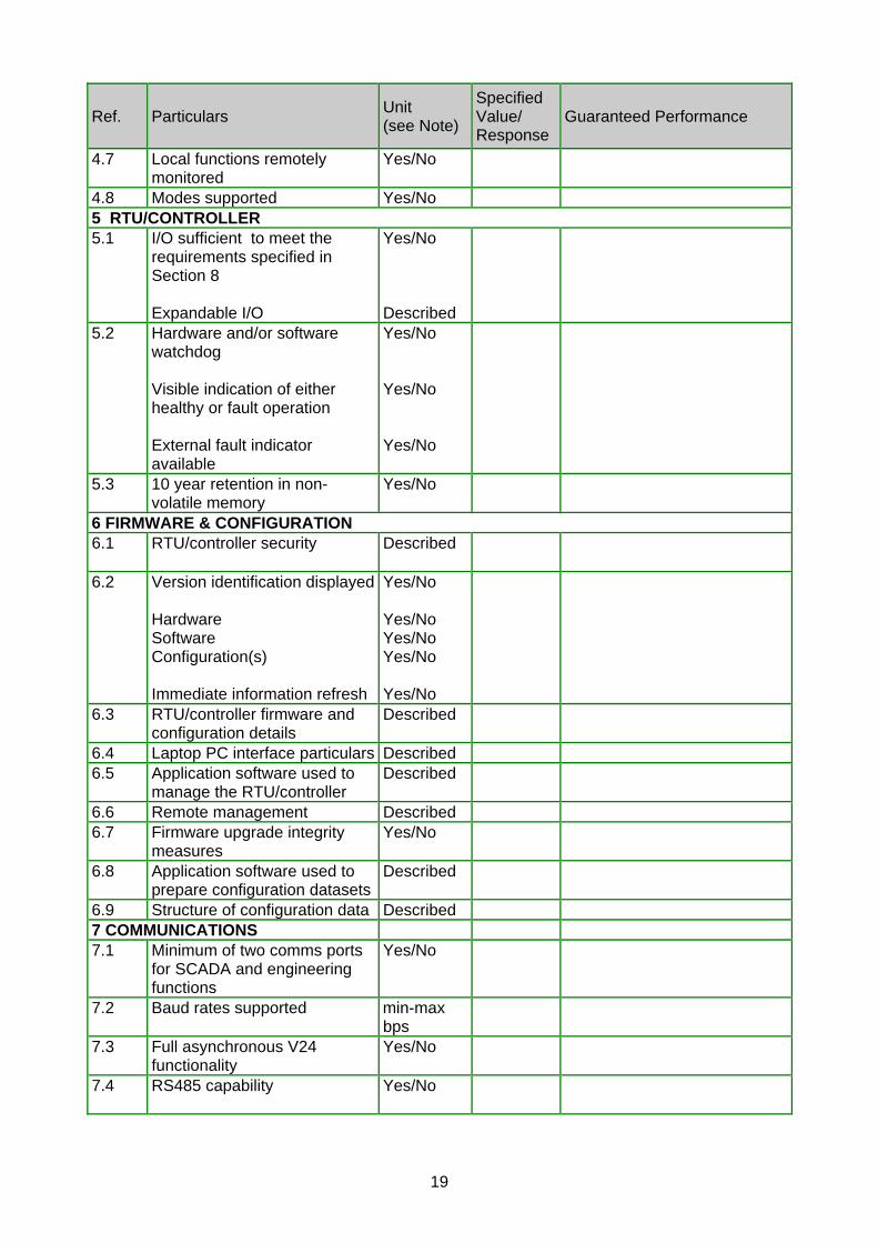
19
Ref. Particulars Unit (see Note)
Specified Value/ Response
Guaranteed Performance
4.7 Local functions remotely monitored
Yes/No
4.8 Modes supported Yes/No 5 RTU/CONTROLLER 5.1 I/O sufficient to meet the
requirements specified in Section 8 Expandable I/O
Yes/No Described
5.2 Hardware and/or software watchdog Visible indication of either healthy or fault operation External fault indicator available
Yes/No Yes/No Yes/No
5.3 10 year retention in non-volatile memory
Yes/No
6 FIRMWARE & CONFIGURATION 6.1 RTU/controller security Described
6.2 Version identification displayed Hardware Software Configuration(s) Immediate information refresh
Yes/No Yes/No Yes/No Yes/No Yes/No
6.3 RTU/controller firmware and configuration details
Described
6.4 Laptop PC interface particulars Described 6.5 Application software used to
manage the RTU/controller Described
6.6 Remote management Described 6.7 Firmware upgrade integrity
measures Yes/No
6.8 Application software used to prepare configuration datasets
Described
6.9 Structure of configuration data Described 7 COMMUNICATIONS 7.1 Minimum of two comms ports
for SCADA and engineering functions
Yes/No
7.2 Baud rates supported min-max bps
7.3 Full asynchronous V24 functionality
Yes/No
7.4 RS485 capability Yes/No

20
Ref. Particulars Unit (see Note)
Specified Value/ Response
Guaranteed Performance
7.5 Remote control of two SVRs with one radio or modem
Described
7.6 Minimum DNP3 requirements met
Yes/No
7.7 Extended datasets remotely accessible via a standard DNP3 mechanism
Yes/No
7.8 DNP3 Device Profile Described 7.9 Evidence of DNP3
conformance testing provided Yes/No
7.10 Redundant DNP3 communications
Described
7.11 Minimum requirements for IP-based communications supported
Yes/No
7.12 Additional, strongly preferred features of IP-based communications
Described
7.13 Additional, desirable features of IP-based communications
Described
8 SCADA I/O 8.1 Minimum DNP3 point set
supported Yes/No
8.2 Comprehensive DNP3 points list
Described
8.3 Cumulative and event-based data
Described
8.4 Time stamps to a resolution of 10ms or better
Yes/No
8.5 Minimum requirements for cumulative and event-based data supported
Yes/No
8.6 Separate data for forward and reverse power flow directions
Yes/No
8.7 Contact wear monitor Described 8.8 Contact wear alarm Described 8.9 Analog accuracy:
Details provided VT accuracy CT accuracy ADC conversion accuracy Digital resolution (no of bits) Overall current and voltage accuracy
Yes/No % % % % %
8.10 IRIG-B time synchronisation Interface
Yes/No Described
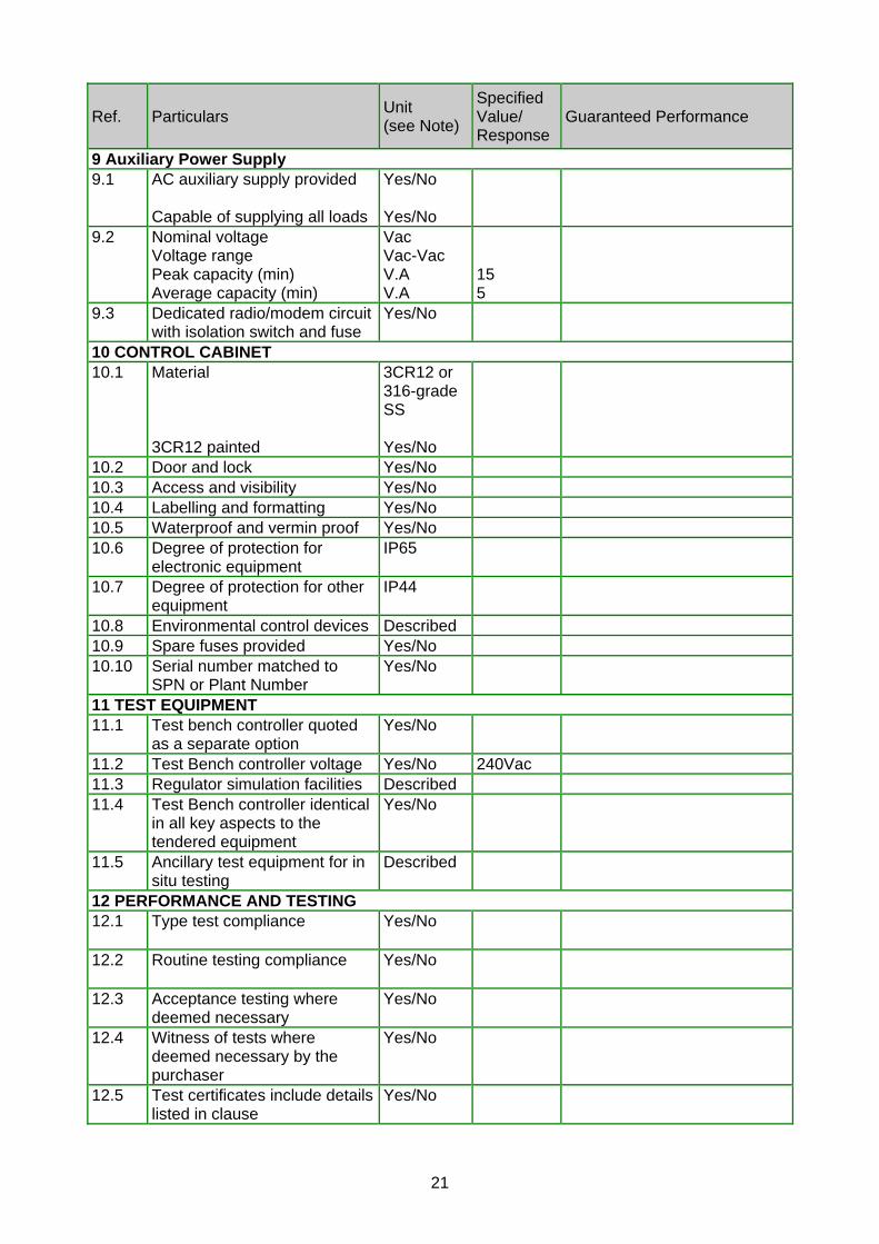
21
Ref. Particulars Unit (see Note)
Specified Value/ Response
Guaranteed Performance
9 Auxiliary Power Supply 9.1 AC auxiliary supply provided
Capable of supplying all loads
Yes/No Yes/No
9.2 Nominal voltage Voltage range Peak capacity (min) Average capacity (min)
Vac Vac-Vac V.A V.A
15 5
9.3 Dedicated radio/modem circuit with isolation switch and fuse
Yes/No
10 CONTROL CABINET 10.1 Material
3CR12 painted
3CR12 or 316-grade SS Yes/No
10.2 Door and lock Yes/No 10.3 Access and visibility Yes/No 10.4 Labelling and formatting Yes/No 10.5 Waterproof and vermin proof Yes/No 10.6 Degree of protection for
electronic equipment IP65
10.7 Degree of protection for other equipment
IP44
10.8 Environmental control devices Described 10.9 Spare fuses provided Yes/No 10.10 Serial number matched to
SPN or Plant Number Yes/No
11 TEST EQUIPMENT 11.1 Test bench controller quoted
as a separate option Yes/No
11.2 Test Bench controller voltage Yes/No 240Vac 11.3 Regulator simulation facilities Described 11.4 Test Bench controller identical
in all key aspects to the tendered equipment
Yes/No
11.5 Ancillary test equipment for in situ testing
Described
12 PERFORMANCE AND TESTING 12.1 Type test compliance Yes/No
12.2 Routine testing compliance Yes/No
12.3 Acceptance testing where deemed necessary
Yes/No
12.4 Witness of tests where deemed necessary by the purchaser
Yes/No
12.5 Test certificates include details listed in clause
Yes/No

22
Ref. Particulars Unit (see Note)
Specified Value/ Response
Guaranteed Performance
13 ELECTROMAGNETIC COMPLIANCE 13.1 Electromagnetic compliance
provided to AS61000 series of standards
Yes/No
13.2 List of AS61000 standards tested against provided. Immunity of equipment classified according to categories provided
Yes/No Yes/No
13.3 Equipment falls within scope of EMC regulations and is appropriately labelled (i.e. C-Tick and a unique supplier identification)
Yes/No
14 RELIABILITY 14.1 Reliability of equipment and
performance of the materials stated
Yes/No
14.2 FMEA analysis provided Yes/No
15 MAINTENANCE 15.1 Frequency and degree of
maintenance required for RTU/controller stated
Yes/No
16 SPARES 16.1 Price list of spares provided Yes/No 16.2 Recommended quantities of
spares Yes/No
16.3 Tenderers to advise of any internal plans to ensure future units are backwards compatible
Yes/No
16.4 Details provided of information tenderer is prepared to supply about the switchgear controls interface
Yes/No
17 SUPPORT SOFTWARE 17.1 List of application software
provided Yes/No
17.2 Minimum hardware and operating system requirements
Described
17.3 End Use Licensing Agreement Described 18 SAMPLES 18.1 Sample of RTU/controller can
be provided for evaluation Yes/No
18.2 Samples to be delivered as required
Yes/No
18.3 Purchase or return of samples Yes/No 18.4 Integration problems to be
resolved Yes/No

23
Ref. Particulars Unit (see Note)
Specified Value/ Response
Guaranteed Performance
19 TRAINING 19.1 Training offerings Described 19.2 RTU/controllers available for
training purposes Yes/No
Name & Signature of Supplier / Date:
Address:
Name & Signature of Witness / Date: