Embed Size (px)
Citation preview

TECHNICAL SERVICE MANUAL
VIKING® HELICAL GEAR REDUCERS "A", "B", AND "C" SIZES
SECTION TSM 610 PAGE 1 OF 9 ISSUE E
VIKING PUMP INC. • A Unit of IDEX Corporation •
CONTENTS Special Information 2 Lubrication 2 Installation 3 Operation 3 Disassembly 3 Assembly "A" 4 "B" 5 "C" 6 Technical Data 7 INTRODUCTION The illustrations used in this manual are for identification purposes only and cannot be used for ordering parts. Obtain a parts list from the factory or a Viking® representative. Always give complete name of part, part number and material with model number and serial number of Reducer when ordering repair parts. The Reducer model number and serial number are on the nameplate. REDUCER NUMBER CHART
"A", "B" AND "C" SIZE REDUCERS SIZE PART NUMBER RATIO
3-551-049-224 2.24:1
3-551-050-276 2.76:1
3-551-051-343 3.43:1 A
3-551-052-417 4.17:1
3-551-054-187 1.87:1 3-551-055-224 2.24:1 3-551-001-276 2.76:1 3-551-002-340 3.40:1 3-551-003-419 4.19:1 3-551-004-506 5.06:1 3-551-005-627 6.27:1
B
3-551-007-765 7.65:1
3-551-056-221 2.21:1
3-551-032-280 2.80:1
3-551-008-331 3.31:1
3-551-009-421 4.21:1
3-551-010-508 5.08:1
3-551-011-624 6.24:1
C
3-551-012-795 7.95:1
FIGURE 1 "A" SIZE HELICAL GEAR REDUCER
FIGURE 2 "B" SIZE HELICAL GEAR REDUCER
FIGURE 3 "C" SIZE HELICAL GEAR REDUCER
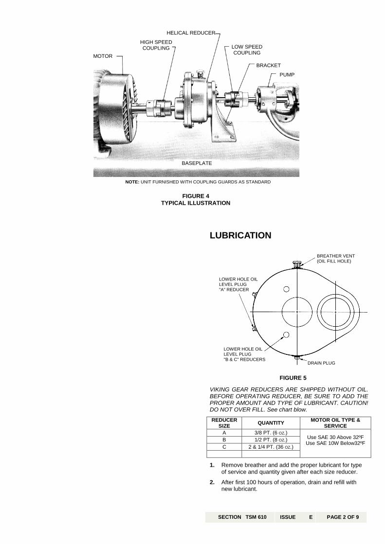
MOTOR
HIGH SPEED COUPLING
HELICAL REDUCER
LOW SPEED COUPLING
BRACKET
PUMP
BASEPLATE
NOTE: UNIT FURNISHED WITH COUPLING GUARDS AS STANDARD
FIGURE 4 TYPICAL ILLUSTRATION
LUBRICATION VIKING GEAR REDUCERS ARE SHIPPED WITHOUT OIL. BEFORE OPERATING REDUCER, BE SURE TO ADD THE PROPER AMOUNT AND TYPE OF LUBRICANT. CAUTION! DO NOT OVER FILL. See chart blow. REDUCER
SIZE QUANTITY MOTOR OIL TYPE & SERVICE
A 3/8 PT. (6 OZ.) B 1/2 PT. (8 OZ.) C 2 & 1/4 PT. (36 OZ.)
Use SAE 30 Above 32ºF Use SAE 10W Below32ºF
1. Remove breather and add the proper lubricant for type
of service and quantity given after each size reducer. 2. After first 100 hours of operation, drain and refill with
new lubricant.
LOWER HOLE OIL LEVEL PLUG "A" REDUCER
BREATHER VENT (OIL FILL HOLE)
LOWER HOLE OIL LEVEL PLUG "B & C" REDUCERS
DRAIN PLUG
FIGURE 5
SECTION TSM 610 ISSUE E PAGE 2 OF 9

3. Check lubricant level every 2000 hours of operation orevery six months, which ever occurs first. Add lubricantas necessary.
4. Once each year drain and refill. If reducer is outdoors,
change to proper lubricant each spring and fall. INSTALLATION Viking helical gear reducers are shipped completelyassembled and ready for installation except for the additionof lubricant. 1. Fasten pump securely to baseplate. 2. Mount reducer on reducer bracket finger tight. The
breather cap should be located on the upper side of thereducer and drain plug on the bottom.
3. Place coupling halves on high and low speed reducer
shafts. 4. Align low speed shaft coupling half with coupling half on
pump or driver shaft. Use straight edge to align couplingas in figure 6. A C-clamp, clamped over pieces ofkeystock, may be used to hold this alignment until themounting bracket is securely bolted to the base plate. Itmay be necessary to shim bracket to extract centerheight of pump or driven shaft. For additional informationon coupling alignment, refer to Engineering ServiceBulletin #ESB 61.
5. Rotate the Reducer in "banana" slots of bracket until
high speed coupling half is at the exact center height ofmotor coupling half.
6. Tighten reducer to bracket securely. 7. Align high speed shaft coupling and fasten motor s securely to base plate. CAUTION : DO NOT EXCEED RECOMMENDED MAXIMUMHORSEPOWER, SEE CATALOG SPECIFICATION SHEET.DO NOT OPERATE BEFORE ADDING LUBRICANT. OPERATION After the first few hours of operation, inspect reducer forleaks. If leakage between gear case and cover cannot bestopped by tightening of nuts or capscrews, the gasketshould be replaced. Leakage around either shaft indicates adamaged lip seal which should be replaced. The operating temperature on the outside of the reducercase, after a few hours operation, should not be more thanapproximately 75º F higher than surrounding air temperature.The oil within the Reducer should never exceed 200º F.
Gear Ratios Four different gear ratios are available for the "A" size Reducers. Eight ratios are available for "B" size reducers and seven ratios for "C" size reducers. Complete reducers within a size may be interchanged on a Viking pump unit to obtain desired pump speeds and capacities. Gear ratios may be changed in all reducers within each size by selecting the proper pinion and gear of a common ratio. A pinion from one ratio cannot be used with a gear from a different ratio. Certain "B" and "C" reducers require additional or different parts besides the pinion and gear to make the ratio change. See chart below for changes required.
SIZE RATIO CHANGES REQUIRED 6.27 to 1 Snap ring for pinion and shaft
B 7.65 to 1 Two spacers (Larger O.D. than used on
other ratios) and gear shaft
C 7.95 to 1 Gear shaft and longer key, also snap ring.
NOTE: SNAP RING FURNISHED WITH "C" 7.95 to 1PINION AND SHAFT.
When changing reducer ratio, nameplate should also be changed to new ratio reducer part number. After making any output or input speed change (complete reducer or gear ratio changes), a check should be made to ensure couplings are of sufficient size for conditions which reducer will be operating. For ratios available see page 1 of this manual, catalog specification sheet or consult factory or Viking representative. DISASSEMBLY Before starting disassembly, study the exploded view (see Fig. 7, 8 or 9) for the particular size reducer that is being disassembled to help determine parts relationship. The parts are indexed in a logical sequence of disassembly and will prove to be a valuable aid in dismantling the reducer. 1. Disconnect couplings and remove capscrews holding
mounting bracket to base. Remove coupling halves and bracket from reducer.
2. Remove breather and drain plugs. Drain all lubricant
from reducer. 3. Remove capscrews from the gear case halves. 4. Tap firmly and alternately on the gear shaft and pinion
shaft. This will separate the reducer halves. 5. With two screwdrivers at opposite sides, carefully pry the
reducer cover loose from internal ball bearings. DO NOT FORCE. Be careful not to damage gasket or gasket surface.
6. Grasp pinion and gear shafts and pull both assemblies
simultaneously from the case or cover. 7. Use a conventional gear or bearing puller to remover
bearing from gear shaft. Remove bevelled spacer on "B" and "C" size reducers. Press shaft from gear.
8. Use puller and remove bearings from pinion shaft.
Remove spacer from "B" size 7.65 to 1 ratio from pinion shaft.
9. Remove lip seals from gear case halves (cover and
case) only if they show signs of deterioration or damage. Lip seals must be pressed or driven out from the inside of gear case and cover on "B" and "C" reducers. "A" size reducer may have lip seals pressed in or out from either side of gear case half.
USE STRAIGHT EDGE. THESE SURFACES MUST BE PARALLEL.
CHECK WIDTH BETWEEN THESE SURFACES WITH INSIDE CALLIPERS TO BE CERTAIN THE FACES ARE EQUAL DISTANCE APART AND PARALLEL
COUPLING ALIGNMENT
FIGURE 6
SECTION TSM 610 ISSUE E PAGE 3 OF 9
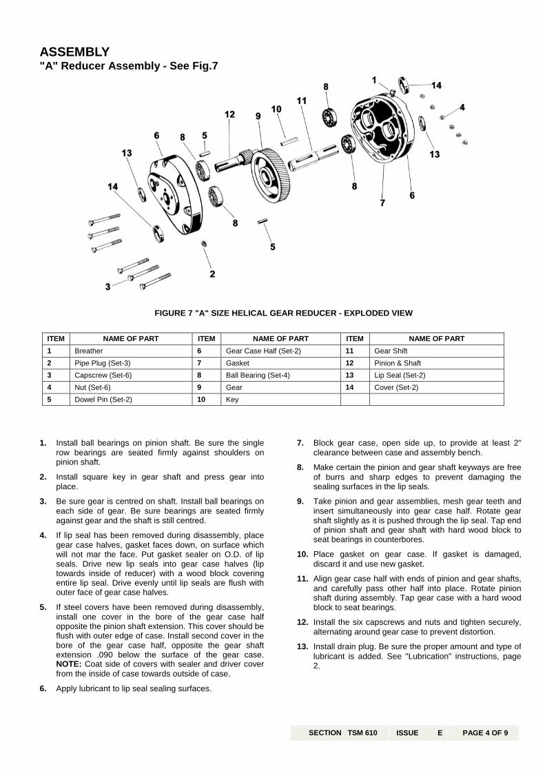
ASSEMBLY "A" Reducer Assembly - See Fig.7
FIGURE 7 "A" SIZE HELICAL GEAR REDUCER - EXPLODED VIEW
1
2
3
4
5
6
ITEM NAME OF PART ITEM NAME OF PART ITEM NAME OF PART 1 Breather 6 Gear Case Half (Set-2) 11 Gear Shift 2 Pipe Plug (Set-3) 7 Gasket 12 Pinion & Shaft 3 Capscrew (Set-6) 8 Ball Bearing (Set-4) 13 Lip Seal (Set-2) 4 Nut (Set-6) 9 Gear 14 Cover (Set-2) 5 Dowel Pin (Set-2) 10 Key
. Install ball bearings on pinion shaft. Be sure the singlerow bearings are seated firmly against shoulders onpinion shaft.
. Install square key in gear shaft and press gear intoplace.
. Be sure gear is centred on shaft. Install ball bearings oneach side of gear. Be sure bearings are seated firmlyagainst gear and the shaft is still centred.
. If lip seal has been removed during disassembly, placegear case halves, gasket faces down, on surface whichwill not mar the face. Put gasket sealer on O.D. of lipseals. Drive new lip seals into gear case halves (liptowards inside of reducer) with a wood block coveringentire lip seal. Drive evenly until lip seals are flush withouter face of gear case halves.
. If steel covers have been removed during disassembly,install one cover in the bore of the gear case halfopposite the pinion shaft extension. This cover should beflush with outer edge of case. Install second cover in thebore of the gear case half, opposite the gear shaftextension .090 below the surface of the gear case.NOTE: Coat side of covers with sealer and driver coverfrom the inside of case towards outside of case.
. Apply lubricant to lip seal sealing surfaces.
7. Block gear case, open side up, to provide at least 2"clearance between case and assembly bench.
8. Make certain the pinion and gear shaft keyways are free
of burrs and sharp edges to prevent damaging thesealing surfaces in the lip seals.
9. Take pinion and gear assemblies, mesh gear teeth and
insert simultaneously into gear case half. Rotate gearshaft slightly as it is pushed through the lip seal. Tap endof pinion shaft and gear shaft with hard wood block toseat bearings in counterbores.
10. Place gasket on gear case. If gasket is damaged,
discard it and use new gasket. 11. Align gear case half with ends of pinion and gear shafts,
and carefully pass other half into place. Rotate pinionshaft during assembly. Tap gear case with a hard woodblock to seat bearings.
12. Install the six capscrews and nuts and tighten securely,
alternating around gear case to prevent distortion. 13. Install drain plug. Be sure the proper amount and type of
lubricant is added. See "Lubrication" instructions, page2.
SECTION TSM 610 ISSUE E PAGE 4 OF 9

ASSEMBLY "B" Reducer Assembly - See Fig. 8
1
2
3
4
FIGURE 8 "B" SIZE HELICAL GEAR REDUCER - EXPLODED VIEW
ITEM NAME OF PART ITEM NAME OF PART ITEM NAME OF PART 1 Drain Plug 9 Ball Bearing 17 Snap Ring (for 6.27 to 1 ratio only) 2 Breather 10 Ball Bearing 18 Pinion and Shaft 3 Pipe Plug (Set-2) 11 Spacer (7.65 to 1 Ratio - 2 Req'd) 19 Snap Ring (Set-2) 4 Capscrew (Set-7) 12 Gear 20 Lip Seal (Set-2) 5 Nut (Set-7) "B" only 13 Key 21 Gear Case 6 Dowel Pin Locating (Set-2) 14 Gear Shaft 7 Gear Case Cover 15 Ball Bearing 8 Gasket 16 Ball Bearing
. Install ball bearing on pinion and shaft. Be sure bearingsare seated firmly against the shoulders on the shaft.
NOTE: "B" reducer with 6.27 to 1 ratio requires a snapring. This snap ring must be installed in the groove onshaft prior to bearing assembly. The bearing should beseated against the snap ring. "B" reducer with 7.65 to 1 ratio requires two spacers, oneon the pinion and shaft and one on the gear shaft. Thespacer for the pinion and shaft should be installed withbevelled edge toward bearing. Install ball bearing onpinion and shaft seating the bearing firmly against thespacer.
. Install square key in gear shaft and press gear into place.Be sure gear seats against shoulder on the shaft.
. Place spacer on gear shaft with bevelled edge toward thegear. Install bearing over gear shaft and seat firmlyagainst spacer. Install a second bearing on large end ofgear shaft and seat bearing firmly against the shaftshoulder.
. If lip seals have removed during disassembly place gearcase and cover, gaskets face down on surface, which willnot mar this face. Be sure snap rings are in the face andcover. Put gasket sealer on the O.D. of lip seals. Drivenew lip seals with lip toward the inside of Reducer, inplace against the snap rings. Use a wood block coveringentire lip seal and drive evenly. Apply lubricant to lip sealsurfaces.
5. Block gear case, open side up, to provide at least 3¼"clearance between case and assembly bench.
6. Make certain the pinion and gear shaft keyways are free
of burrs and sharp edges to prevent damaging the lipseal sealing surfaces. Take pinion and gear assemblies,mesh gear teeth, and insert simultaneously into gearcase half. Rotate gear shaft slightly as it is pushedthrough lip seal. Tap end of pinion shaft and gear shaftwith hardwood block to seat bearings in counter bores.
7. Place gasket on gear case. If gasket is damaged,
discard it and use new gasket. 8. Align gear case cover with ends of pinion and gear
shafts, and carefully push cover into place. Rotate pinionshaft during assembly. Tap cover with a hardwood blockto seat bearings in cover.
9. Install the seven capscrews and nuts and tighten
securely, alternating around gear case to preventdistortion.
10. Install drain plug. Be sure the reducer is filled with proper
lubricant. See "Lubrication" instructions, page 2.
SECTION TSM 610 ISSUE E PAGE 5 OF 9

ASSEMBLY "C" Reducer Assembly - See Fig. 9
1.
2.
3.
4.
ITEM NAME OF PART ITEM NAME OF PART ITEM NAME OF PART 1 Drain Plug 7 Gasket 14 Gear Shaft 2 Breather 9 Ball Bearing (Double Row) 15 Ball Bearing (Double Row) 3 Pipe Plug (Set-2) 10 Ball Bearing (Single Row) 16 Ball Bearing (Single Row) 4 Capscrew (Set-2) 11 Spacer 17 Pinion and Shaft 5 Dowel Pin Locating (Set-2) 12 Gear 18 Snap Ring (Set-2) 6 Gear Case Cover 13 Key 19 Lip Seal (Set-2)
Install ball bearing on pinion small diameter end, and singlBe sure bearings are seated on the shaft.
NOTE: Pinion and shaft for "Cfurnished with a snap ringinstalled in the groove on assembly. The bearing shouldring.
Install square key in gear shaBe sure gear seats against sh
Place spacer on gear shaft wgear. Install bearing over gagainst spacer. Install a secogear shaft and seat bearinshoulder.
If lip seals have removed durincase and cover, gaskets face not mar this face. Be sure snacover. Put gasket sealer on thnew lip seals with lip toward thplace against the snap rings. Uentire lip seal and drive evenlysurfaces.
FIGURE 9 "C" SIZE HELICAL GEAR REDUCER - EXPLODED VIEW
shaft double row bearing one row bearing on large end.firmly against the shoulders
" reducer (7.95 to 1 ratio) is. This snap ring must bethe shaft prior to bearing be seated against the snap
ft and press gear into place.oulder on the shaft.
ith bevelled edge toward theear shaft and seat firmlynd bearing on large end ofg firmly against the shaft
g disassembly place gear down on surface, which will p rings are in the face and e O.D. of lip seals. Drive e inside of Reducer, in se a wood block covering
. Apply lubricant to lip seal
5. Block gear case, open side up, to provide at least 3¾"clearance between case and assembly bench.
6. Make certain the pinion and gear shaft keyways are free
of burrs and sharp edges to prevent damaging the lipseal sealing surfaces. Take pinion and gear assemblies,mesh gear teeth, and insert simultaneously into gearcase half. Rotate gear shaft slightly as it is pushedthrough lip seal. Tap end of pinion shaft and gear shaftwith hardwood block to seat bearings in counter bores.
7. Place gasket on gear case. If gasket is damaged,
discard it and use new gasket. 8. Align gear case cover with ends of pinion and gear
shafts, and carefully push cover into place. Rotate pinionshaft during assembly. Tap cover with a hardwood blockto seat bearings in cover.
9. Install the seven capscrews and nuts and tighten
securely, alternating around gear case to preventdistortion.
10. Install drain plug. Be sure the reducer is filled with proper
lubricant. See "Lubrication" instructions, page 2.
SECTION TSM 610 ISSUE E PAGE 6 OF 9

1. Determine ratio to obtain desired output speed. 2. Determine actual horsepower requirements of application. 3. Determine equivalent horsepower for the application by
multiplying the actual horsepower to be transmitted by the appropriate service factors, which can be obtained in the Service Facto Table below.
This service factor takes into account the time length ofservice per day, the load classification (uniform, moderateshock, heavy shock), and the type of drive.
4. Refer to the recommended maximum reducer horsepower
line in the horsepower tables below and make sure theequivalent horsepower for a given input speed and ratio isless than or equivalent to the maximum recommendedhorsepower shown in the chart.
SELECTING THE CORRECT VIKING HELICAL GEAR REDUCER
POWER SOURCE 1 3 CHARACTER OF DRIVEN LOAD 2 3
Electric Motor, Steam Turbine, or Hydraulic Motor
Uniform Moderate Shock
Heavy Shock Multi-Cylinder
Internal Combustion Engine
Uniform Moderate Shock
Heavy Shock
1. For applications driven by single cylinder e2. Rotary pump applications are considered a3. Use of belt or chain type drives to either re "A" Size Helical Reducer HorsePart No./Ratio (3-551-049-224/2.24:1) (
VIKING GHIGH SPEED SHAFT
INPUT RPM 1 2.24:1 2780
1750 6.1 640
1450 5.2 520
1150 4.3 420
950 3.6
1 For input speeds higher than 1750 RPM, consu
"B" Size Helical Reducer HorPart No./Ratio (3-551-054-187/1.87:(3-551-003-419/4.19:1) (3-551-004-5
VIKING GHIGH SPEED SHAFT
INPUT RPM 1 1.87:1 2.24:1 2.76:1 950 780 640
1750 19.0 17.0 15.0 780 640 520
1450 17.3 15.5 13.4 640 520 420
1150 16.5 14.0 11.6 520 420 350
950 15.5 12.8 10.1
1 For input speeds higher than 1750 RPM, consu
Service Factor Table
INTERMITTENT UP TO 3 HRS. A DAY
8-10 HRS. A DAY
24 HRS. A DAY
.8 1.0 1.5
1.0 1.25 1.75
1.25 1.5 2.0
1.0 1.25 1.5
1.25 1.751.5 2.0
1.75 2.25
ngines, refer to factory for other service factors.s uniform loads. ducer input or output shaft is not recommended.
power Table 3-551-050-276/2.76:1) (3-551-051-343/3.43:1) (3-551-052-417/4.17:1)
EAR REDUCER RATIOS "A" SIZE .76:1 3.43:1 4.17:1
640 520 420 LOW SPEED SHAFT RPM 4.9 3.8 3.1 MAXIMUM REDUCER HP 520 420 350 LOW SPEED SHAFT RPM 4.2 3.2 2.7 MAXIMUM REDUCER HP 420 350 280 LOW SPEED SHAFT RPM 3.4 2.6 2.2 MAXIMUM REDUCER HP 350 280 230 LOW SPEED SHAFT RPM 2.9 2.2 1.8 MAXIMUM REDUCER HP
lt the factory.
sepower Table1) (3-551-055-224/2.24:1) (3-551-001-276/2.76:1) (3-551-002-340/3.40:1) 06/50.6:1) (3-551-005-627/6.27:1) (3-551-007-765/7.65:1)
EAR REDUCER RATIOS "B" SIZE 3.40:1 4.19:1 5.06:1 6.27:1 7.65:1
520 420 350 280 230 LOW SPEED SHAFT RPM 13.0 11.0 9.5 7.6 6.4 MAXIMUM REDUCER HP 420 350 280 230 190 LOW SPEED SHAFT RPM 11.6 9.9 8.5 6.4 5.4 MAXIMUM REDUCER HP 350 280 230 190 155 LOW SPEED SHAFT RPM 10.1 8.5 7.3 5.3 4.4 MAXIMUM REDUCER HP 280 230 190 155 125 LOW SPEED SHAFT RPM 9.0 7.6 6.0 4.3 3.7 MAXIMUM REDUCER HP
lt the factory.
SECTION TSM 610 ISSUE E PAGE 7 OF 9
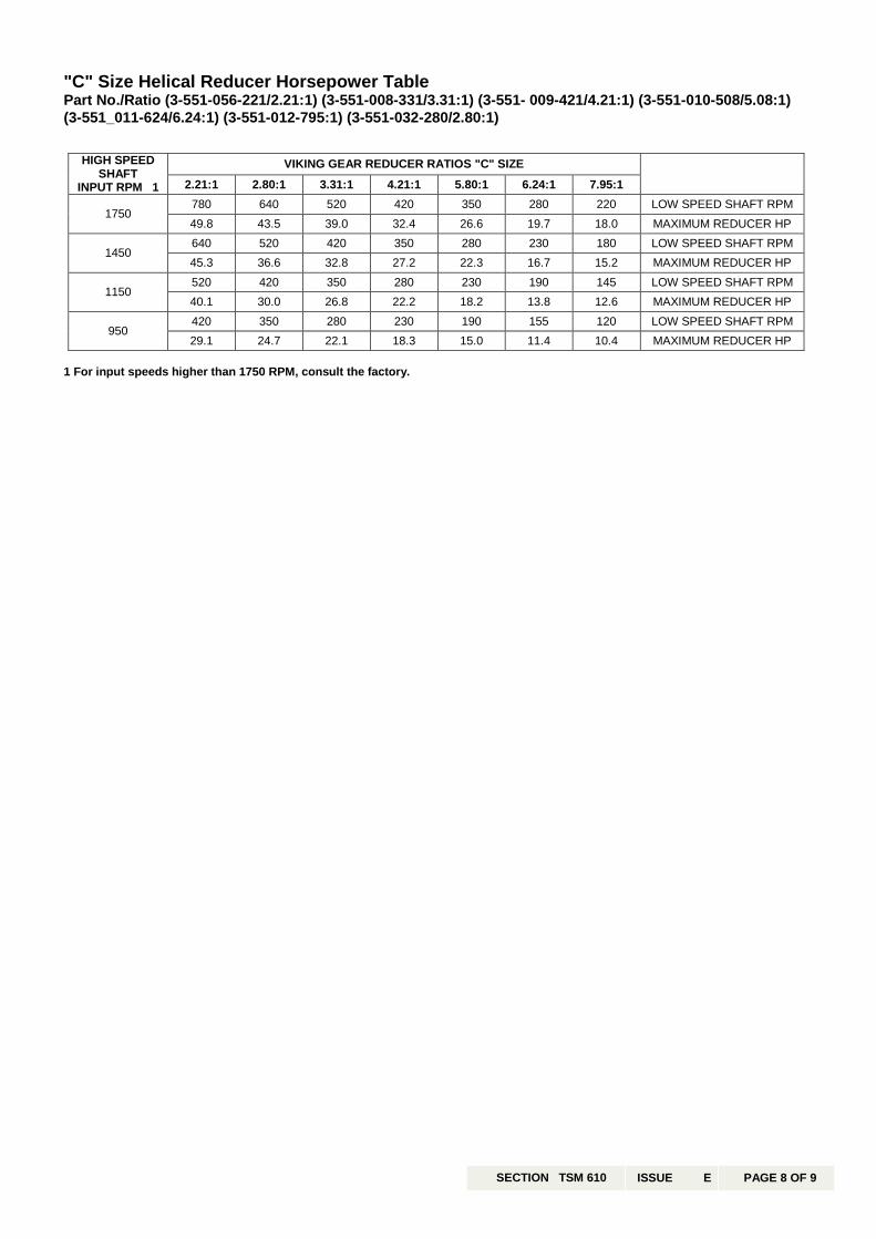
"C" Size Helical Reducer Horsepower TablePart No./Ratio (3-551-056-221/2.21:1) (3-551-008-331/3.31:1) (3-551- 009-421/4.21:1) (3-551-010-508/5.08:1)(3-551_011-624/6.24:1) (3-551-012-795:1) (3-551-032-280/2.80:1)
VIKING GEAR REDUCER RATIOS "C" SIZE HIGH SPEED SHAFT
INPUT RPM 1 2.21:1 2.80:1 3.31:1 4.21:1 5.80:1 6.24:1 7.95:1
780 640 520 420 350 280 220 LOW SPEED SHAFT RPM 1750
49.8 43.5 39.0 32.4 26.6 19.7 18.0 MAXIMUM REDUCER HP 640 520 420 350 280 230 180 LOW SPEED SHAFT RPM
1450 45.3 36.6 32.8 27.2 22.3 16.7 15.2 MAXIMUM REDUCER HP 520 420 350 280 230 190 145 LOW SPEED SHAFT RPM
1150 40.1 30.0 26.8 22.2 18.2 13.8 12.6 MAXIMUM REDUCER HP 420 350 280 230 190 155 120 LOW SPEED SHAFT RPM
950 29.1 24.7 22.1 18.3 15.0 11.4 10.4 MAXIMUM REDUCER HP
1 For input speeds higher than 1750 RPM, consult the factory.
SECTION TSM 610 ISSUE E PAGE 8 OF 9

VIKING PUMP INC. • A Unit of IDEX Corporation •
SECTION TSM 610 PAGE 9 of 9 ISSUE E
WARRANTY
Viking warrants all products manufactured by it to be
free from defects in workmanship or material for aperiod of one (1) year from date of startup, providedthat in no event shall this warranty extend more thaneighteen (18) months from the date of shipment fromViking. If, during said warranty period, any productssold by Viking prove to be defective in workmanship ormaterial under normal use and service, and if suchproducts are returned to Viking’s factory at Cedar Falls,Iowa, transportation charges prepaid, and if theproducts are found by Viking to be defective inworkmanship or material, they will be replaced orrepaired free of charge, FOB. Cedar Falls, Iowa.
Viking assumes no liability for consequentialdamages of any kind and the purchaser by acceptanceof delivery assumes all liability for the consequences ofthe use or misuse of Viking products by the purchaser,his employees or others. Viking will assume no fieldexpense for service or parts unless authorized by it inadvance.
Equipment and accessories purchased by Vikingfrom outside sources which are incorporated into anyViking product are warranted only to the extent of andby the original manufacturer’s warranty or guarantee, ifany.
THIS IS VIKING’S SOLE WARRANTY AND IS INLIEU OF ALL OTHER WARRANTIES,EXPRESSED OR IMPLIED, WHICH AREHEREBY EXCLUDED, INCLUDING INPARTICULAR ALL WARRANTIES OFMERCHANTABILITY OR FITNESS FOR APARTICULAR PURPOSE. No officer or employee of IDEX Corporation orViking Pump, Inc. is authorized to alter thiswarranty.
TECHNICAL SERVICE MANUALVIKING® HELICAL GEAR REDUCERS
"A", "B", AND "C" SIZES
VIKING PUMP INC.∙ Copyright 2000∙