Embed Size (px)
Citation preview

TECHNICAL REVIEWDanish Primary Laboratory of AcousticsMicrophone Reciprocity CalibrationCalculation Program for ReciprocityCalibration
Brüel B K7/6-'89& Kjær
NO. 1 1998
BV
0051
–11
ISSN
000
7–26
21omslag.qxd 19/08/98 19:01 Page 2

TechnicalReviewNo. 1 – 1998
Contents
Danish Primary Laboratory of Acoustics (DPLA) as Part ofthe National Metrology Organisation ........................................................ 1Kim Carneiro
Pressure Reciprocity Calibration – Instrumentation, Resultsand Uncertainty .............................................................................................. 5Erling Frederiksen and Jørgen I.Christensen
MP.EXE, a Calculation Program for Pressure ReciprocityCalibration of Microphones ....................................................................... 27Knud Rasmussen
Copyright © 1998, Brüel & Kjær Sound & Vibration Measurement A/S
All rights reserved. No part of this publication may be reproduced or distributed in any form, or by any means, without prior written permission of the publishers. For details, contact: Brüel & Kjær Sound & Vibration Measurement A/S, DK-2850 Nærum, Denmark.Editor: Harry K. Zaveri Photographer: Peder DalmoLayout: Helle Smidt Printed by SLM Grafisk

Previously issued numbers ofBrüel & Kjær Technical Review1–1997 A New Design Principle for Triaxial Piezoelectric Accelerometers
A Simple QC Test for Knock SensorsTorsional Operational Deflection Shapes (TODS) Measurements
2–1996 Non-stationary Signal Analysis using Wavelet Transform, Short-time Fourier Transform and Wigner-Ville Distribution
1–1996 Calibration Uncertainties & Distortion of Microphones.Wide Band Intensity Probe. Accelerometer Mounted Resonance Test
2–1995 Order Tracking Analysis1–1995 Use of Spatial Transformation of Sound Fields (STSF) Techniques in the
Automative Industry2–1994 The use of Impulse Response Function for Modal Parameter Estimation
Complex Modulus and Damping Measurements using Resonant and Non-resonant Methods (Damping Part II)
1–1994 Digital Filter Techniques vs. FFT Techniques for Damping Measurements (Damping Part I)
2–1990 Optical Filters and their Use with the Type 1302 & Type 1306 Photoacoustic Gas Monitors
1–1990 The Brüel&Kjær Photoacoustic Transducer System and its Physical Properties
2–1989 STSF — Practical Instrumentation and ApplicationDigital Filter Analysis: Real-time and Non Real-time Performance
1–1989 STSF — A Unique Technique for Scan Based Near-Field Acoustic Holography Without Restrictions on Coherence
2–1988 Quantifying Draught Risk1–1988 Using Experimental Modal Analysis to Simulate Structural Dynamic
ModificationsUse of Operational Deflection Shapes for Noise Control of Discrete Tones
4–1987 Windows to FFT Analysis (Part II)Acoustic Calibrator for Intensity Measurement Systems
3–1987 Windows to FFT Analysis (Part I)2–1987 Recent Developments in Accelerometer Design
Trends in Accelerometer Calibration1–1987 Vibration Monitoring of Machines4–1986 Field Measurements of Sound Insulation with a Battery-Operated
Intensity AnalyzerPressure Microphones for Intensity Measurements with Significantly Improved Phase PropertiesMeasurement of Acoustical Distance between Intensity Probe Microphones
(Continued on cover page 3)

Previously issued numbers ofBrüel & Kjær Technical Review(Continued from cover page 2)
Wind and Turbulence Noise of Turbulence Screen, Nose Cone and Sound Intensity Probe with Wind Screen
3–1986 A Method of Determining the Modal Frequencies of Structures with Coupled ModesImprovement to Monoreference Modal Data by Adding an Oblique Degree of Freedom for the Reference
2–1986 Quality in Spectral Match of Photometric TransducersGuide to Lighting of Urban Areas
1–1986 Environmental Noise Measurements4–1985 Validity of Intensity Measurements in Partially Diffuse Sound Field
Influence of Tripods and Microphone Clips on the Frequency Response of Microphones
3–1985 The Modulation Transfer Function in Room AcousticsRASTI: A Tool for Evaluating Auditoria
2–1985 Heat StressA New Thermal Anemometer Probe for Indoor Air Velocity Measurements
1–1985 Local Thermal Discomfort4–1984 Methods for the Calculation of Contrast
Proper Use of Weighting Functions for Impact TestingComputer Data Acquisition from Brüel&Kjær Digital Frequency Analyzers 2131/2134 Using their Memory as a Buffer
Special technical literatureBrüel&Kjær publishes a variety of technical literature which can be obtained from your local Brüel&Kjær representative.The following literature is presently available:
❍ Acoustic Noise Measurements (English), 5th. Edition❍ Noise Control (English, French)❍ Frequency Analysis (English), 3rd. Edition❍ Catalogues (several languages)❍ Product Data Sheets (English, German, French, Russian)
Furthermore, back copies of the Technical Review can be supplied as shown in the list above. Older issues may be obtained provided they are still in stock.

Danish Primary Laboratory of Acoustics (DPLA) as Part of the National Metrology Organisation
Kim Carneiro*
When the Danish Government, in 1989, nominated the Danish Primary Labo-ratory of Acoustics (DPLA), it was probably the first time that an instrumentmanufacturer (Brüel&Kjær) became involved in the maintenance of nationalmeasurement standards. Even if this action is uncommon, it was part of adeliberate strategy for building a viable Danish metrology organisation; andafter several years of operation it is fair to conclude that it has worked outvery well. The present article describes some of the thoughts that went behindit and some of the factors that have contributed to its success.
In the early 1980’s Denmark found itself without a national metrology insti-tute that could meet the present and foreseen needs of Danish industry. Anational accreditation scheme was in place, but measurement traceability wasnot taken care of in a way that foreign trading partners would accept as ade-quate for an industrial country. A parliamentary commission was chargedwith a report and as a result it was decided to establish the Danish Institute ofFundamental Metrology (DFM) as well as a decentralised organisation of com-petent primary and national reference laboratories. DPLA was the first pri-mary laboratory to be nominated outside DFM.
The reason for this decision was the same as the reason that had led to theestablishment of the accreditation service some ten years earlier. As a smallcountry (5 million inhabitants) with an industry consisting of mainly smallenterprises with a widespread need in measurements and testing, it was real-ised that the state budget could not sustain a metrology infrastructure thatwould satisfy even a significant fraction of the needs. On the other hand some-thing had to be done to change the reputation of Danish metrology from beingmediocre to good. It was therefore decided to privatise and liberalise measure-ment and testing through accreditation and to establish a decentralisedmetrology organisation which, apart from DFM, was built on expertise availa-ble at institutions or companies outside the traditional metrology circles.Brüel&Kjær was immediately recognised as a candidate for a national labora-tory for acoustics and vibrations.
In accordance with overall plans for development of metrology in Denmark,DPLA maintains standards for airborne acoustics and vibrations in Denmark.
* Director of Danish Institute of Fundamental Metrology (DFM) Byg. 307;Anker Engelunds vej 1; 2800 Lyngby
1

Being a joint operation between the Technical University of Denmark andBrüel&Kjær, DPLA combines academic science with the manufacture of preci-sion instruments; although an unorthodox establishment it has been able toperform as a respected national laboratory, with the following tasks:
1) Participation in international comparisons. DPLA compares its pri-mary standards on a regular basis with NIST, it has taken part inEUROMET comparisons and is being proposed as a pilot laboratory forEAL-comparisons.
2) Dissemination of traceable measurements within Denmark. DPLAoffers accredited calibration with traceability to its primary standards.
3) Participation in international metrology collaboration. DPLA is repre-sented in a number of standardisation committees and DPLA has beena valued partner, when other countries were looking for help to estab-lish metrology facilities to meet their needs.
4) Teaching. The unique mix of expertise in DPLA has made it possible toteach at all levels in metrology, from the highest academic level to downto earth industrial level.
Of course, entrusting a commercial enterprise with the maintenance ofnational measurement standards, cannot be granted without conditions, if thenational credibility is to be accepted by the foreign trading partners with verydifferent policies for the deployment of measurement standards. Thereforevery stringent principles are applied before a Danish primary laboratory isnominated by the National Agency for Trade and Industry. These are:
a) International evaluation. Before nomination, candidates are evaluatedby an international team, ensuring the adequate competence withrespect to all functions as a national laboratory. Particular attention isgiven to whether the applicant possesses primary standards in whichcase it is nominated primary laboratory. Otherwise, if the candidate istraceable to a foreign laboratory, the nomination is for national refer-ence laboratory.
b) Dissemination of accredited calibration. The calibration of the nationallaboratory must be performed under a DANAK accreditation. Thisensures the quality of the traceability to the national standards, be pri-mary or secondary; and it also ensures the impartiality of the laboratoryas manifested in clause 4 of EN45001.
The nomination of DPLA was a landmark in Danish metrology, since it wasthe first nomination involving a private production industry. It has later beenfollowed by several other examples, so that the Danish organisation of metrol-ogy laboratories presently consist of 9 participants. They represent Universi-ties, state-operated laboratories, independent research organisations. Theyare assembled in DANIAmet and closely supervised by the National Agency.
2

3

4

Pressure Reciprocity Calibration – Instrumentation, Results andUncertainty
Erling Frederiksen and Jørgen I. Christensen.
AbstractThis article is written in connection with the release of a new automatedMicrophone Reciprocity Calibration System for national and other high levelcalibration laboratories. The accuracy of practically all acoustic measure-ments is based on pressure reciprocity calibrations. The principle of this pri-mary calibration method is briefly described together with a more detaileddescription of the past and present reciprocity measurement instruments andsystems which have been produced by Brüel&Kjær for more than 40 years.To cover the need for calibrations within the company, Brüel&Kjær has notonly produced such instruments but has also for about 30 years operated itsown primary calibration laboratory and used the instruments for periodic cal-ibrations. The article describes calibration comparisons and spread of resultsobtained during this time. It also describes the calculated uncertainty validfor customer calibrations performed since 1991 when Brüel&Kjær's primarylaboratory got status of a technically independent department and was nomi-nated by the government as the Danish Primary Laboratory of Acoustics.
RésuméCet article accompagne la présentation d’un nouveau Système automatiséd’Etalonnage de microphones par réciprocité destiné aux centres d’étalonnageprimaires à l’échelon national. La précision de la plupart des mesures acous-tiques est basée sur un étalonnage primaire par réciprocité en pression. Leprincipe de cette procédure y est décrit brièvement. Cette description s’accom-pagne d’une rétrospective plus détaillée de l’instrumentation et des systèmesBrüel&Kjær consacrés aux mesures par réciprocité depuis plus de quaranteans. Pour couvrir les besoins internes à l’entreprise, la société Brüel&Kjærgère également depuis trois décennies son propre laboratoire d’étalonnage pri-
5
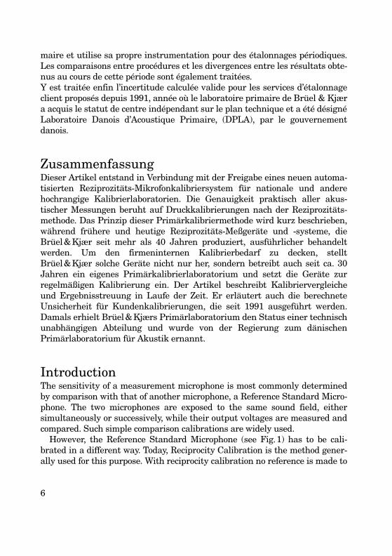
maire et utilise sa propre instrumentation pour des étalonnages périodiques.Les comparaisons entre procédures et les divergences entre les résultats obte-nus au cours de cette période sont également traitées.Y est traitée enfin l’incertitude calculée valide pour les services d’étalonnageclient proposés depuis 1991, année où le laboratoire primaire de Brüel & Kjæra acquis le statut de centre indépendant sur le plan technique et a été désignéLaboratoire Danois d’Acoustique Primaire, (DPLA), par le gouvernementdanois.
ZusammenfassungDieser Artikel entstand in Verbindung mit der Freigabe eines neuen automa-tisierten Reziprozitäts-Mikrofonkalibriersystem für nationale und anderehochrangige Kalibrierlaboratorien. Die Genauigkeit praktisch aller akus-tischer Messungen beruht auf Druckkalibrierungen nach der Reziprozitäts-methode. Das Prinzip dieser Primärkalibriermethode wird kurz beschrieben,während frühere und heutige Reziprozitäts-Meßgeräte und -systeme, dieBrüel&Kjær seit mehr als 40 Jahren produziert, ausführlicher behandeltwerden. Um den firmeninternen Kalibrierbedarf zu decken, stelltBrüel&Kjær solche Geräte nicht nur her, sondern betreibt auch seit ca. 30Jahren ein eigenes Primärkalibrierlaboratorium und setzt die Geräte zurregelmäßigen Kalibrierung ein. Der Artikel beschreibt Kalibriervergleicheund Ergebnisstreuung in Laufe der Zeit. Er erläutert auch die berechneteUnsicherheit für Kundenkalibrierungen, die seit 1991 ausgeführt werden.Damals erhielt Brüel&Kjærs Primärlaboratorium den Status einer technischunabhängigen Abteilung und wurde von der Regierung zum dänischenPrimärlaboratorium für Akustik ernannt.
IntroductionThe sensitivity of a measurement microphone is most commonly determinedby comparison with that of another microphone, a Reference Standard Micro-phone. The two microphones are exposed to the same sound field, eithersimultaneously or successively, while their output voltages are measured andcompared. Such simple comparison calibrations are widely used.
However, the Reference Standard Microphone (see Fig.1) has to be cali-brated in a different way. Today, Reciprocity Calibration is the method gener-ally used for this purpose. With reciprocity calibration no reference is made to
6

any acoustic quantity like microphone sensitivity (V/Pa) nor sound pressure(Pa) but only to fundamental electrical, mechanical and physical parameterslike DC voltage, frequency, length, air density, temperature, static pressureetc. Such a method of calibration is called an absolute or primary calibrationmethod while comparison calibration is a secondary method.
Primary calibration methods are used by relatively few laboratories, such asNational Calibration Laboratories and few large automotive, space or govern-mental organizations which work at a high technological level. Secondarymethods are used by several laboratories for calibration and verification ofcommonly used measurement microphones.
Like other measurement probes and transducers the microphone due to itspresence disturbs the field and therefore influences the quantity to be meas-ured, the sound pressure. This influence depends partly on the microphoneitself and partly on the type of sound field. Thus microphones have differentsensitivities for the three principal types of field, i.e. pressure-field, free-fieldand diffuse-field.
In principle, the three different types of sensitivity may be found by perform-ing pressure-field, free-field and diffuse-field reciprocity calibrations. However,diffuse-field reciprocity calibration especially is associated with serious techni-cal problems and is therefore not used in practice. Free-field reciprocity cali-
Fig. 1. The Brüel & Kjær Laboratory Standard Microphones Type 4160 (23.77 mm diame-ter – named one inch) and Type 4180 (half inch diameter) are the Reference StandardMicrophones which are most commonly used by national and other well established cali-bration laboratories. The microphones meet the requirements valid for types LS2p andLS1p of the international standard IEC 61094-1
7

bration is technically less complicated and works well, especially at higherfrequencies, but it is quite costly to perform. It requires an anechoic room andgreat care needs to be taken to avoid noise and cross-talk problems.
Pressure-field reciprocity calibration is in practice the most easy and lesscostly method. By proper instrumentation a high accuracy and repeatabilitymay be reached and a wide frequency range may be covered with this method.
The pressure reciprocity calibration leads to the pressure sensitivity only.However, for a specific type of microphone the free-field and diffuse-field sensi-tivities differ from the pressure-field sensitivity only by essentially fixed fre-quency dependent constants. Therefore, if these constants are known, free-field and diffuse-field sensitivities may be obtained by correcting measuredpressure sensitivities.
Today, pressure calibrations are performed by several laboratories in theworld while only few laboratories are able to make free-field calibrations. Someleading acoustic calibration laboratories have published corrections whichmake it possible to determine free-field and diffuse-field sensitivities frommeasured pressure sensitivities. This has contributed towards making thepressure reciprocity calibration the most widely used method for primarymicrophone calibration.
Pressure Reciprocity Calibration PrincipleReciprocity calibration can be made with reciprocal transducers only. The con-denser microphone which can work in two different modes, either as areceiver or a transmitter of sound is a reciprocal transducer. It emits sound ifcurrent is fed through its electrical terminals.
More specifically for a microphone to be reciprocal it must behave like a pas-sive, linear two-port network with a ratio of response to excitation which is thesame for the two operation modes. For a condenser microphone this meansthat the ratio of output voltage to acoustic volume velocity (receiver operation)must be equal to the ratio of pressure on diaphragm to electrical input current(transmitter operation). The conditions are to be valid with unloaded electricalterminals and with blocked diaphragm respectively.
The reciprocity theorem is not only valid for the condenser microphone itselfbut also for the combined electrical, mechanical and acoustical network whichis made up of a transmitter and a receiver microphone coupled to each othervia an acoustic impedance. This makes reciprocity calibration possible. Duringpressure reciprocity calibration the microphones are coupled together by theair (gas) enclosed in a cavity. One microphone operates as transmitter and
8

emits sound into the cavity which is detected by the receiver microphone. Thedimensions of the cavity and the acoustic impedance of the microphones mustbe known while the properties (pressure, temperature and composition) of thegas (air) in the coupler must be controlled or monitored in connection with themeasurement. These parameters are used for the succeeding calculations ofAcoustic Transfer Impedance and microphone sensitivity. Three microphones (A, B and C) are used, see Fig.2. They are pair-wise (AB,BC and CA) coupled together. For each pair the receiver output voltage andthe transmitter input current are measured and their ratio which is called theElectrical Transfer Impedance is calculated. After having determined the elec-trical impedance and calculated the acoustic transfer impedance for eachmicrophone combination, the sensitivities of all the three microphones may becalculated by solving the equations below.
(Eq.1,2and3)
where
Fig. 2. Principle of Pressure Reciprocity Calibration. The 3 microphones (A, B and C) arecoupled 2 at a time together by the air (or gas) enclosed in a cavity while the three ratios ofoutput voltage and input current are measured. Each ratio equals the Electrical TransferImpedance valid for the respective pair of microphones
B
A
iAB
uAB
Receivers
Coupler
Transmitters
C
B
iBC
uBC
A
C
iCA
uCA
980200e
Mp A, Mp B,×Ze AB,Za AB,----------------- Mp B, M×
p C,
Ze BC,Za BC,----------------- Mp C, Mp A,×
Ze CA,Za CA,-----------------=;=;=
Ze AB,uABiAB----------- Ze BC,
uBCiBC----------- Ze CA,
uCAiCA-----------=;=;=
9

The international Pressure Reciprocity Calibration Standard IEC61094-2(renamed from IEC1094-2) gives much more information and details, espe-cially on the determination of the Acoustic Transfer Impedance. In the middleof the frequency range this is essentially determined by the volume of the cou-pler cavity and of the properties of the enclosed air (gas) but it is also influ-enced by the acoustic impedance of the microphone diaphragms.
In the lower part of the frequency range the acoustic transfer impedance isin addition also influenced by the heat conduction process which occurs at thecoupler surfaces and leads to a decreasing pressure with decreasing frequency.The calibration results have to be corrected for the influence of this effectwhich today is carefully analyzed and described in the IEC standard.
At higher frequencies, where the wavelengths approach the dimensions ofthe coupler cavity the acoustic transfer impedance becomes highly influencedby wave motion in the cavity. This complicates an accurate determination ofthe impedance. In principle there are two ways to overcome this problem. Oneway is to minimize the wave motion by replacing the air in the coupler by a gashaving a high speed of sound, like Helium or Hydrogen. Another possibility isto shape the coupler in such a way that the influence of the wave motionbecomes predictable by simple and reliable calculations. As the first method
Mp,A , Mp,B, Mp,C : Pressure Sensitivities of microphones A, B and C
Za,AB, Za,BC, Za,CA : Acoustic Transfer Impedances of coupler with micro-phones AB, BC and CA
Ze,AB, Ze,BC, Ze,CA : Electrical Transfer Impedances of coupler with micro-phones AB, BC and CA
Fig. 3. Plane Wave Coupler and its model. The model uses a transmission line to representthe coupler cavity. This is terminated by acoustic impedances which represent the micro-phone diaphragms
MicrophoneX
MicrophoneY
Diaphragm
Front Cavity
Diaphragm
Front Cavity
TransmissionLineZa,X Za,Y
980201e
CouplerCavity
10

implies several practical problems the second method is today the most com-monly used. With this method the coupler cavity is shaped like a cylinder withsame diameter as the microphone diaphragms. Wave motion will occur in suchcouplers but essentially only in the axial direction. Such couplers are calledplane wave couplers, see Fig.3. Their shape and dimensions make it possibleto calculate the acoustic transfer impedance by using the theory of transmis-sion lines. The expression below originates from IEC61094-2 and defines theacoustic transfer impedance.
The transfer impedance Za, XY is given by:
(Eq.4)
where
Za,0: Characteristic impedance of acoustic transmission line with crosssection area like the coupler cavity
Za ,X , Za,Y : Acoustic diaphragm impedance of the microphones (X and Y ): Complex propagation coefficient
lXY : Coupler cavity length
To summarize the above description, a reciprocity calibration requires meas-urement of electrical transfer impedance and determination of acoustic trans-fer impedance for each pair of microphones followed by a sensitivitycalculation involving solution of the above shown equations 1, 2 and 3.
History of Pressure Reciprocity Calibration InstrumentsIn the Fourties the reciprocity calibration method was invented and initiallyanalysed at the National Bureau of Standards USA by RichardK.Cook. In theFifties the first standard instrument for reciprocity calibration was developedby Brüel&Kjær. It was basically an instrument with facilities for mountingthe microphones and coupler and for measurement of the transmitter micro-phone current. An external generator and a measurement amplifier whichserved as a voltmeter were connected to the instrument.
1Za XY,-----------------
1 Za 0,------------
Za 0,Za X,------------- a 0,Z
Za Y,-------------
γ( lXY )⋅cosh+
=
1Za 0,Za X,-------------+
+Za 0,Za Y,-------------⋅
γ lXY )⋅(sinh
γ
11

In this type of instrument the current of the transmitter microphone wasdetermined by measuring the voltage across a calibrated capacitor which wasconnected in series with the transmitter. Proper selection of capacitancemakes this voltage (which represents the transmitter current) of the sameorder of magnitude as the receiver output voltage, independent of the fre-quency. Thus the determination of the electrical transfer impedance becomes ameasurement of a voltage ratio which can be carried out easily and accurately.This method is still being used with B&K reciprocity calibration instruments.
The first types of instruments measured the combined sensitivity of themicrophone and the applied preamplifier. In some cases this was afterwardscorrected for the loading and for the gain of the preamplifier to obtain the opencircuit sensitivity. Later preamplifiers with insert voltage facility becameavailable. The insert voltage calibration technique makes it possible to correctfor the loading and determine the open circuit sensitivity directly. Today this isthe sensitivity which is generally measured and stated by primary calibrationlaboratories. The open circuit sensitivity is valid for a standardized configura-tion and dimensions of preamplifier terminals and is not related to any specificpreamplifier, see IEC61094-1.
In the beginning of the Seventies Brüel&Kjær developed a self-containedcalibration instrument Reciprocity Calibration Apparatus Type 4143 whichonly needed an external generator, see Fig.4. This instrument which is stillwidely used, represented a great step forward with respect to accurate deter-mination of the electrical transfer impedance.
The instrument which contains a precision voltage comparator and attenua-tor reduced the uncertainty of the measured electrical transfer impedances bya factor of five to ten and made future improvements of accuracy a question ofbetter determination of the acoustic transfer impedance.
In the past reciprocity calibration systems were manually operated. Thismade the measurements and succeeding calculations a very time consumingtask. Therefore, it was common to limit the number of calibrations as much as
Fig. 4. Reciprocity Calibration Apparatus Type 4143. Manual instrument for reciprocitycalibration of microphones which is widely used today
12

possible by having long time intervals between the periodic calibrations and bymeasuring at only a few frequencies.
Even though this type of instrument was faster than its predecessors it wasstill quite slow. This was changed when Brüel&Kjær modified some of themfor automatic PC controlled operation. The first modifications were made foruse within the company itself in 1991 when Brüel&Kjær was officially nomi-nated as the Danish Primary Laboratory of Acoustics.
The experience with this type of system finally lead to the development andrelease of a completely new PC controlled calibration system in 1997. The fea-tures of this fast and accurate system is described in the following.
New Pressure Reciprocity Calibration SystemThe new pressure reciprocity calibration system Type 9699 consists of the fol-lowing main parts:
1) An automated system for measurement of voltage ratio (electricaltransfer impedance).
2) A pair of plane wave couplers for each microphone dimension (one inchand half inch).
3) A sensitivity calculation program developed according to IEC61094-2(MP.exe).
4) A measurement chamber for noise reduction, static pressure stabiliza-tion and pressurization.
Automated Voltage Ratio Measurement SystemA block diagram of the measurement system is shown in Fig. 5. The coreinstrument, the Reciprocity Calibration Apparatus Type 5998 contains twomeasurement channels with identical signal conditioning amplifiers andselectable high pass filters for low frequency noise reduction. The receivermicrophone is mounted on a preamplifier with insert voltage facility which isconnected to one of the channels. The transmitter microphone is mounted on atransmitter unit and is connected to the other channel. This unit contains aknown series capacitor for measurement of the transmitter microphone cur-rent. Both preamplifier and transmitter units have low output impedancewhich make it possible to place the microphones being calibrated remote fromthe measurement system itself.
The signal generator supplies the driving signal to the transmitter micro-phone via an amplifier contained in Type 5998 and via the transmitter unit.The output voltage of the two measurement channels is measured by the dig-
13
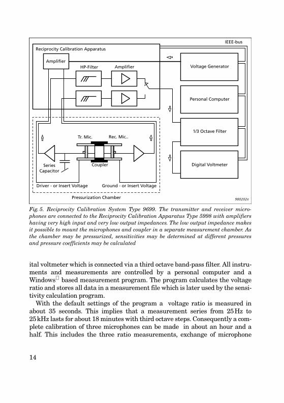
ital voltmeter which is connected via a third octave band-pass filter. All instru-ments and measurements are controlled by a personal computer and aWindows based measurement program. The program calculates the voltageratio and stores all data in a measurement file which is later used by the sensi-tivity calculation program.
With the default settings of the program a voltage ratio is measured inabout 35 seconds. This implies that a measurement series from 25Hz to25kHz lasts for about 18 minutes with third octave steps. Consequently a com-plete calibration of three microphones can be made in about an hour and ahalf. This includes the three ratio measurements, exchange of microphone
Fig. 5. Reciprocity Calibration System Type 9699. The transmitter and receiver micro-phones are connected to the Reciprocity Calibration Apparatus Type 5998 with amplifiershaving very high input and very low output impedances. The low output impedance makesit possible to mount the microphones and coupler in a separate measurement chamber. Asthe chamber may be pressurized, sensitivities may be determined at different pressuresand pressure coefficients may be calculated
Reciprocity Calibration Apparatus
AmplifierHP-Filter Amplifier
Tr. Mic. Rec. Mic..
SeriesCapacitor
Coupler
Driver - or Insert Voltage Ground - or Insert Voltage
Voltage Generator
Personal Computer
1/3 Octave Filter
Digital Voltmeter
IEEE-bus
Pressurization Chamber 980202e
14

pairs and time for the succeeding sensitivity calculation. With the previousmanual systems such a calibration would have taken several days.
High reproducibility and high absolute accuracy of the voltage ratio meas-urements have been main design goals for Type 9699. Therefore, special atten-tion has been paid to reduction of environmental and inherent noise and ofcross-talk which may disturb the measurements.
The design of the measurement chamber and the low-pass and band-passfilters give a good signal to noise ratio also under laboratory conditions whereno specific attention has been paid to background noise. This implies a repeat-ability of the voltage ratio measurements better than 0.004dB above 31.6Hzand better than 0.002dB above 125 Hz, see Fig.6. It also means that this ran-dom error has only minor influence on the overall calibration uncertainty.
Systematic errors may occur due to gain difference between the receiver andtransmitter measurement channels of the Reciprocity Apparatus and due tonon-linearity of the voltmeter. Therefore, a high quality voltmeter is chosenand the minor gain difference which may occur is automatically measured bythe insert voltage calibration technique and is incorporated in the calculationsat each frequency.
Fig.6. Random error of Voltage Ratio measurements obtained with Type 9699. The graphshows 2 values (95% confidence level) determined from 10 measurements at each frequency
Fig. 7. Systematic error of Voltage Ratio measurement. The error is measured by using anelectrical reference standard which is developed by National Physical Laboratory (UK).The result is obtained with a system similar to Type 9699 used by DPLA (explained later)
Type 4180,Random error (2σ)of Voltage Ratio Measurement
0.00010
0.005
dB
0.010
100 1000 10000 Hz 100000980193e
σ
Systematic error (2σ) ofVoltage Ratio Measurement
– 0.005
0.005
dB
0.015
10 100 1000 10000 Hz 100000980194e
15
A few years ago an internal Brüel&Kjær calibration system (which is simi-lar to this new system) was tested by using an electrical reference standardwhich simulates a coupler with two microphones. This reference which wascalibrated by the National Physical Laboratory in London replaced the acous-tic parts during the test. The result showed that the systematic error of themeasured voltage ratio was very small and also that the principle of theapplied system was quite adequate, see Fig.7.
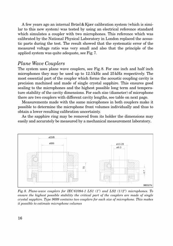
Plane Wave CouplersThe system uses plane wave couplers, see Fig.8. For one inch and half inchmicrophones they may be used up to 12.5kHz and 25kHz respectively. Themost essential part of the coupler which forms the acoustic coupling cavity isprecision machined and made of single crystal sapphire. This ensures goodsealing to the microphones and the highest possible long term and tempera-ture stability of the cavity dimensions. For each size (diameter) of microphonethere are two couplers with different cavity lengths, see table on next page.
Measurements made with the same microphones in both couplers make itpossible to determine the microphone front volumes individually and thus toobtain a lower resulting calibration uncertainty.
As the sapphire ring may be removed from its holder the dimensions mayeasily and accurately be measured by a mechanical measurement laboratory.
Fig. 8. Plane-wave couplers for IEC 61094-1 LS1 (1") and LS2 (1/2") microphones. Toensure the highest possible stability the critical part of the couplers are made of singlecrystal sapphire. Type 9699 contains two couplers for each size of microphone. This makesit possible to estimate microphone volumes
ø18.6
ø23.85
7.5
ø9.34.
7ø13.28
980327e
16

Measurement ChamberType 5998 includes a measurement chamber which encloses the microphonesand the coupler; see Fig.9. As mentioned above the chamber attenuates theambient noise around the microphones by about 30dB and makes valid meas-urements possible even in quite noisy laboratory environments. The chambermay also be used for stabilization of the static pressure around the coupler andmicrophones. This means that highly repeatable measurements can be madealso on days with non-stable weather. Finally the chamber may be pressurizedpermitting measurements at different ambient pressures. This facility is espe-cially important for accurate comparison of calibration results between labora-tories located at different heights above sea level.
The same facility may also be used for determination of static pressure coefficientsof Reference Standard Microphones. The sensitivity coefficients shown in Fig.10were thus calculated after reciprocity calibrations at two different static pressures.
Today it is common to accept the performance of calibration at the presentambient static pressure. This measurement chamber makes it possible to cali-brate at the reference pressure itself (usually 101.325 kPa).
CouplerType
MicrophoneType
Volume(mm3)
Length(mm)
Diameter(mm)
FrequencyRange
(Hz)UA1413 (1")UA1429 (1")UA1414 (1/2")UA1430 (1/2")
IEC-LS1p (4160)IEC-LS1p (4160)IEC-LS2p (4180)IEC-LS2p (4180)
40762038639319
15.07.59.44.7
18.618.69.39.3
20 – 700020 – 1250020 – 1300020 – 25000
Fig. 9. The sound isolating measurement chamber of Type 9699. The chamber may bepressurized to any value between that of sea level and Mexico City
17

Sensitivity Calculation ProgramThe system includes a program for calculation of the microphone sensitivities(MP.exe). This program is developed by the Department of Acoustic Technol-ogy of the Danish Technical University, Lyngby in accordance with the stand-ard for pressure reciprocity calibration (IEC61094-2). The standard and theprogram contain the necessary detailed information about the determinationof the acoustic transfer impedance (see Eq. 1, 2 and 3) of the couplers. The pro-gram gets its input data from the measurement file and from files which storethe coupler dimensions and acoustic impedance of the microphones.
The program calculates the sensitivities of the three microphones at themeasurement conditions. The sensitivity at the commonly applied referenceambient conditions (101.325kPa, 23°C and 50%RH) is also calculated. Thisadditional calculation is based on average values of measured temperatureand pressure sensitivity coefficients of several Brüel&Kjær Laboratory Stand-ard Microphones. A description of the program is given in a separate article.
The automated measurements and PC calculations have simplified the cali-bration process and made it applicable also for less specialized acoustic cali-bration laboratories. The calibration uncertainty which can be expected for theType 9699 system is described below.
Fig. 10. Individual Static Pressure Coefficients of Laboratory Standard Microphones Type4160. The Coefficients are determined from reciprocity calibrations made at two differentambient pressures by using the measurement chamber
0
– 0.01
dB/kPa
– 0.03
– 0.02
100001000 Hz10010980338e
Type 4160 873975 873982 512330
18
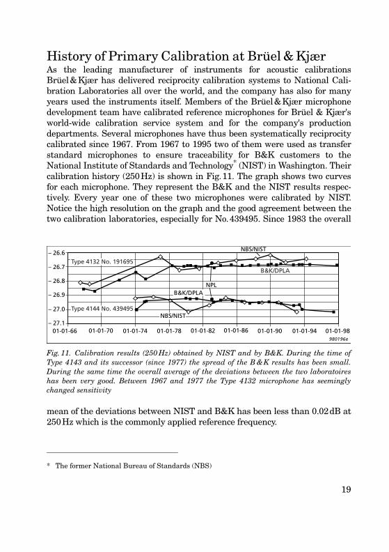
History of Primary Calibration at Brüel & KjærAs the leading manufacturer of instruments for acoustic calibrationsBrüel&Kjær has delivered reciprocity calibration systems to National Cali-bration Laboratories all over the world, and the company has also for manyyears used the instruments itself. Members of the Brüel&Kjær microphonedevelopment team have calibrated reference microphones for Brüel & Kjær'sworld-wide calibration service system and for the company's productiondepartments. Several microphones have thus been systematically reciprocitycalibrated since 1967. From 1967 to 1995 two of them were used as transferstandard microphones to ensure traceability for B&K customers to theNational Institute of Standards and Technology* (NIST) in Washington. Theircalibration history (250Hz) is shown in Fig.11. The graph shows two curvesfor each microphone. They represent the B&K and the NIST results respec-tively. Every year one of these two microphones were calibrated by NIST.Notice the high resolution on the graph and the good agreement between thetwo calibration laboratories, especially for No.439495. Since 1983 the overall
mean of the deviations between NIST and B&K has been less than 0.02dB at250Hz which is the commonly applied reference frequency.
* The former National Bureau of Standards (NBS)
Fig. 11. Calibration results (250 Hz) obtained by NIST and by B&K. During the time ofType 4143 and its successor (since 1977) the spread of the B &K results has been small.During the same time the overall average of the deviations between the two laboratoireshas been very good. Between 1967 and 1977 the Type 4132 microphone has seeminglychanged sensitivity
NBS/NIST
B&K/DPLANPL
B&K/DPLA
NBS/NIST
Type 4144 No. 439495
– 26.6
– 26.8
– 27.0
– 26.9
– 27.1
– 26.7
01-01-66 01-01-70 01-01-74 01-01-78 01-01-82 01-01-86 01-01-90 01-01-94 01-01-98980196e
Type 4132 No. 191695
19

During the years comparisons have been made with several other calibra-tion laboratories. After the international round robin calibration which wascompleted in 1983 a comparison was made with National Physical Laboratory(NPL) in London. This result is also shown in Fig.11.
For microphone No.191695 the graph shows a change in the sensitivityresults between 1969 and 1978. This change of nearly 0.2dB was detected byboth laboratories. Therefore, the change is most probably due to a mechanicalchange in the microphone and not due to uncertainty of the calibrations. Suchmechanical changes may occur but they rarely cause sensitivity changes aslarge as this. When such changes are seen with laboratory standard micro-phones they are typically of the order of 0.01dB to 0.02dB. Even if most refer-ence microphones stay stable it is thus recommended to use a set of at leastthree microphones for all important standards like National Reference Stand-ards.
Since 1967 B&K has used three different reciprocity calibration systems andinstruments. Type 4142 was used until 1975-76. At that time it was replacedby Type 4143 which can measure voltage ratios much more accurately by usinga precision attenuator and an accurate meter. This improvement is clearlyreflected in the much better reproducibility of the results from 1976 to 1990,see Fig. 11.
In 1991 the Danish Government nominated Brüel&Kjær as the Danish Pri-mary Laboratory of Acoustics (DPLA). The nomination was based on the com-pany's know-how and experience with microphone and accelerometercalibration. Due to the nomination and the generally increasing need for cali-bration, B&K made an automated calibration system for DPLA (an independ-ent department of B&K). The operation principle of this Type 4143 basedsystem is similar to that of the newly released Type 9699 system. This systemhas been used during the Nineties. As can be seen the automated calibrationsmade since 1990 are in good agrement with the previous results, see Fig. 11.
Fig. 12. Reciprocity calibration results (250 Hz) obtained with a one inch microphone Type4160. The deviation from a linear regression line is < 0.01 dB (2 ) over a period of 14years
250 Hz
– 26.68
– 26.72
– 26.7601-01-84 01-01-86 01-01-88 01-01-90 01-01-92 01-01-94 01-01-96 01-01-98
980197e
Type 4160 No. 873982
σ
20
Today, the above-mentioned microphone types (Type 4132 and Type 4144)are not used as NIST transfer standards. For this and most other referenceapplications these types have been replaced by Type 4160. This type is pro-duced within more narrow tolerances, is better documented and has a fixedcavity in front of the diaphragm which is formed by a non-removeable ring.Type 4160 is, therefore, better suited for accurate and repeatable calibrationsthan the previous types. See 250Hz results from 1984 to 1998 in Fig.12. Today,Type 4160 is routinely calibrated from 31.5Hz to 10kHz.
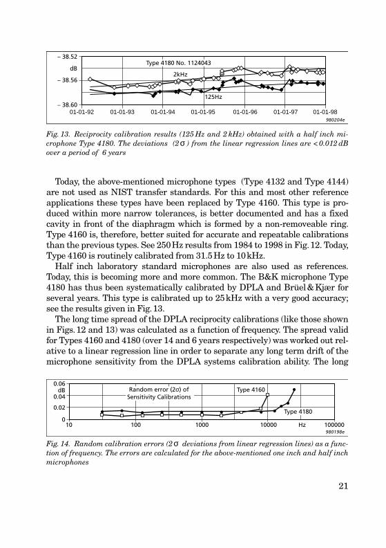
Half inch laboratory standard microphones are also used as references.Today, this is becoming more and more common. The B&K microphone Type4180 has thus been systematically calibrated by DPLA and Brüel&Kjær forseveral years. This type is calibrated up to 25kHz with a very good accuracy;see the results given in Fig.13.
The long time spread of the DPLA reciprocity calibrations (like those shownin Figs.12 and 13) was calculated as a function of frequency. The spread validfor Types 4160 and 4180 (over 14 and 6 years respectively) was worked out rel-ative to a linear regression line in order to separate any long term drift of themicrophone sensitivity from the DPLA systems calibration ability. The long
Fig. 13. Reciprocity calibration results (125 Hz and 2 kHz) obtained with a half inch mi-crophone Type 4180. The deviations (2 ) from the linear regression lines are < 0.012 dBover a period of 6 years
Fig. 14. Random calibration errors (2 deviations from linear regression lines) as a func-tion of frequency. The errors are calculated for the above-mentioned one inch and half inchmicrophones
2kHz
– 38.60
– 38.56
– 38.52
dB
01-01-9301-01-92 01-01-94 01-01-95 01-01-96 01-01-97 01-01-98980204e
Type 4180 No. 1124043
125Hz
σ
0.06dB
0.04
0.02
0
Type 4160
980198e10 100 1000 10000 Hz 100000
Random error (2σ) ofSensitivity Calibrations
Type 4180
σ
21

term spread (2 ) which contains random errors of both the acoustical and theelectrical transfer impedances and of the ambient microphone corrections wasfound to be close to 0.01dB for both types. It was slightly lower for Type 4160than for Type 4180 and increased for both types above 4kHz, see Fig.14.
Calibration Results Obtained with Type 9699The calibration system Type 9699 is new. Therefore, no historical sensitivityresults have been produced to create confidence in the system. To overcomethis problem a series of measurements were made to compare the results ofthe new system with those of the old DPLA system which has produced highlyreproducible and reliable results over the last 6 years.
Series of measurements were made with both half inch and one inch micro-phones and with both short and long plane-wave couplers. All measurementswhich were made with a certain set of microphone and a specific coupler wereperformed on the same day with both calibration systems. No differencesbetween the results could be traced back to the two systems. An example of aresult valid for a half inch microphone is shown in Fig.15. This shows compar-ison of microphone sensitivity as measured with the two systems with a longcoupler (31.6Hz to 2kHz) and with a short coupler (31.6kHz to 25kHz). Allresults are displayed relative to their average value.
The series of measurements made to test the new system showed that thisproduces reproducible and reliable results which are comparable with those ofthe well-documented and established DPLA system.
Fig. 15. Calibration result (example) obtained for microphone Type 4180 No. 1124043with a Type 9699 system (new) and with the well-documented Type 4143 system. A series ofmeasurements have shown that no difference can be traced back to system differences
σ
0.04
dB
0
– 0.04
980199e10 100 1000 10000 Hz 100000
Comparison of Type 4180 calibrations made with Types 9699 and 4143
Type 4143: Solid dotsType 9699: Open dots
22

Uncertainty of DPLA’s Primary Pressure CalibrationsIn connection with the formation of DPLA the Danish government requiredthat DPLA should achieve an accreditation from the Danish AccreditationBody DANAK. Therefore, the uncertainty of the primary microphone reciproc-ity calibration had to be further analysed and evaluated. The required analy-sis which was made in 1991 did not lead to any significant changes, neither ofthe measurement nor of the calculation procedures. No step change can,therefore, be seen on the long term sensitivity graphs; see example in Fig.12.The uncertainty of DPLA calibrations is claimed to be ±0.03dB (2 ) for oneinch microphones in the best frequency range (125Hz to 4kHz) while it is±0.04dB for half inch microphones. NIST stated ±0.08dB for their calibra-tions. The uncertainty calculations are discussed below.
This section deals with calculation of DPLA’s calibration uncertainty. It brieflydescribes the applied calculation method and shows the results obtained forthe Types 4160 and 4180. The sensitivity of a microphone (A) is determinedfrom acoustical and electrical transfer impedances (Za and Ze) which are validfor the three pairs of microphones (AB, BC, CA). It is defined by the equationbelow which is derived from Equations 1, 2 and 3.
(Eq. 5)
According to general uncertainty calculation principles and to the Guide to theExpression of Uncertainty in Measurement which is issued by BIPM, ISO, IECand other organizations the overall uncertainty of the sensitivity determina-ton is given by the square-root of the sum of variances valid for the acousticaland electrical impedances. Each of them are influenced by the uncertainty ofseveral input quantities.
It should be noted that a systematic error of a specific quantity influences alleletrical or all acoustical impedances equally (see Eq.5) while a random errorinfluences them differently. A systematic error is thus partly equalized due toits correlated influence on the numerator and the denominator. The effect of asystematic error corresponds to influencing one parameter only while all threeare influenced by a random error. The ratio between influences of equally largesystematic and random errors is thus 1: . After determination of the system-
σ
Mp A,Za BC,
Za AB, Za CA,×----------------------------------------
Ze AB, Ze CA,×Ze BC,
---------------------------------------×=
3
23

atic and the random error of each specific input parameter they are combinedby using the above weighting factors, see Eq.6.
(Eq.6)
(Eq.7)
: Calculated uncertainty (dB) of microphone pressure sensitivity: Systematic uncertainty of input quantity (i) influencing the
pressure sensitivity: Random uncertainty of input quantity (i) influencing the pres-
sure sensitivity1.. .N : Identification numbers of input quantities
: Change of sensitivity for change of input quantity (i)
The influence of an input parameter error depends on the parameter itselfand on the frequency. Its contribution to the uncertainty of the calculated sen-sitivity was found by multiplying the error by a coefficient which representsthe frequency dependent sensitivity to a change in the specific parameter.
Fig. 16. Calculated and specified uncertainty for customer calibrations performed byDPLA. It was considered that the values and equations stated in IEC 61094-2 are correct.The uncertainty belongs to the best in the world of National Laboratories
Qi Qi sys,2
3( Qi ran, )2∆×
0,5+∆
=∆
Mp f( ) dB[ ] ∆Qi
dMp f )(dQi
--------------------× dB ][ 2
i 1=
i N=
∑≅∆
∆Mp f )(∆Qi sys,
∆Qi ran,
dMp f )(dQi
-------------------
0
0.04
0.08
dB
0.12
10 100 1000 10000 Hz 100000980203e
Type 4160
Type 4160
Type 4180
24

The coefficients were determined by using the reciprocity sensitivity calcula-tion program. Variations in calculated sensitivity were related to variations ininput parameters.
The uncertainty of the microphone sensitivity which is valid at measure-ment conditions were found in accordance with Equation 7. The sensitivity atambient reference conditions is found by correcting that valid for measure-ment conditions. The uncertainty of the corrections were calculated andincluded in the overall uncertainty of the sensitivity shown in Fig.16.
For this calculation it was considered that the contents of the InternationalStandard IEC61094-2 is correct. The calculation therefore does not take possi-ble errors in the standard and its principles into account.
The uncertainty of DPLA is low and among the very best in the world. Thisis partly due to the experience and routine gained with the high calibrationactivity of the laboratory and partly due to the modern calibration systemwhich works with a high reproducibility and small systematic errors.
However, there is always a risk of human errors. To keep this risk low DPLAalways includes at least one own reference microphone with a long term cali-bration history when reciprocity calibrations are made for customers. If a cali-bration error should occur the calibration result of this microphone will mostprobably differ from those of the history and indicate that something is wrong.
Possible future efforts to improve the calibration uncertainty should be con-centrated on parameters which influence the acoustic transfer impedance. Thepressure and temperature of the coupler gas would be important together withthe impedance of the microphone diaphragms and front cavities. Also micro-phone coefficients for static pressure and temperature should be further ana-lyzed. The measurement chamber of Type 9699 which may be pressurized canbe used for that.
ConclusionIntensive research, new international standards and new improved instru-ments for pressure reciprocity calibration have lead to microphone sensitivityresults which today are 5 to 10 times better than they were 30 years ago. Theresults of today are better with respect to reproducibility and to overall uncer-tainty.
Furthermore, the new calibration systems which are automated haveimproved the productivity of reciprocity systems by at least 10 times and thusmade calibrations over wide frequency ranges possible in practice. The risk of
25
operator errors is also reduced with the new system as both measurementsand calculations are controlled by PC software.
The measurement chamber which is a part of the Calibration System Type9699 eases inter-laboratory comparison calibrations and measurement ofmicrophone pressure coefficients as it may be pressurized to any pressurebetween that at sea level and that at a high altitude city such as Mexico City.
Today, half inch microphones are increasingly used as Reference StandardMicrophones but long series of calibration results have shown that the repeat-ability obtainable with one inch microphones is slightly better. Therefore, oneinch microphones will probably also be used in the future, especially for themost accurate calibrations below 4 to 8kHz while half inch microphones willcover the full range up to 25kHz.
Uncertainty calculations are made for one and half inch microphone calibra-tions. Below 10kHz the results are practically equal for the two sizes and theyare close to 0.02dB (2 ). For these uncertainty calculations the considerationsof the international standard IEC61094-2 were assumed to be correct. TheDanish Primary Laboratory of Acoustics specifies tolerances for customer cali-brations which are approximately twice as large.
References[1] "Measurement microphones", International Standard, IEC61094-1,
1992–05
[2] "Primary method for pressure calibration of laboratory standard micro-phones by the reciprocity technique", International Standard,IEC61094-2, 1992-03
[3] "Primary method for free-field calibration of laboratory standard micro-phones by the reciprocity technique", International Standard,IEC61094-3, 1995-11
σ
26

MP.EXE, a Calculation Programfor Pressure Reciprocity Calibrationof Microphones
Knud Rasmussen*
A computer program is described which calculates the pressure sensitivity ofmicrophones based on measurements of the electrical transfer impedance in areciprocity calibration set-up. The calculations are performed according to theInternational Standard IEC61094-2. In addition a number of options allowsthe user to improve his calculations by introducing corrections not yet imple-mented in IEC61094-2 such as corrections for the influence of radial wave-motion in the couplers. A special feature, the ability to refer the calculatedsensitivities to reference environmental conditions by means of the complexstatic pressure- and temperature coefficients for B&K Types 4160 and 4180microphones, is included in the program.
RésuméLe logiciel pour PC décrit ici calcule la sensibilité en pression des microphonessurla base de l’impédance électrique de transfert entre deux microphonesplacés dans un montage de mesure d’étalonnage par réciprocité. Les calculssont effectués selon la Norme internationale CEI61094-2. Un certain nombrede fonctions permet d’améliorer les calculs par l’introduction de correctionsnon encore mises en œuvre par cette Norme, telles que la correction de l’influ-ence du déplacement des ondes radiales dans les coupleurs. Une caractéris-tique spéciale a été incluse au logiciel : la possibilité de lier les sensibilitéscalculées aux conditions environnementales de référence par le biais des coef-ficients de température et de pression statique pour les Microphones B&KType 4160 et 4180.
* Danish Primary Laboratory of Acoustics, DTU Branch, Department of Acoustic Technology, Danish Technical University
27

ZusammenfassungEs wird ein Computerprogramm beschrieben, das den Druck-Übertragungs-faktor von Mikrofonen auf der Basis von Messungen der elektrischen Über-tragungsimpedanz in einer Einrichtung zur Reziprozitätskalibrierungberechnet. Die Berechnungen werden nach der internationalen NormIEC61094-2 ausgeführt. Darüber hinaus erlauben mehrere Optionen demBenutzer, seine Berechnungen durch Korrekturen zu verbessern, die nochnicht in IEC61094-2 implementiert sind, z.B. für den Einfluß radialer Wellen-bewegung in den Kupplern. Eine Besonderheit des Programms ist die Mög-lichkeit, die berechneten Übertragungsfaktoren auf Bezugs-Umgebungs-bedingungen zu beziehen. Dies erfolgt mit Hilfe der komplexen statischenDruck- und Temperaturkoeffizienten für die Brüel&Kjær-Mikrofone 4160und 4180.
IntroductionMP.EXE is a computer program which calculates the pressure sensitivity oflaboratory standard microphones as defined in IEC Publication 61094-1,1992, ref.[1], based on measurement results obtained by a reciprocity calibra-tion in a closed coupler, performed as laid down in IEC Publication 61094-2,1992, ref.[2].
The program is originally developed at the Department of Acoustic Technol-ogy, Technical University of Denmark for research purposes and later devel-oped into a more universal program covering virtually all possible aspects forperforming a reciprocity pressure calibration using three microphones, mutu-ally coupled by a passive cylindrical coupler as described in ref.[2].
The program is written so that it can be executed without user communica-tion if the measurement data filename is given as a parameter when callingthe program and provided that the necessary microphone and coupler datafiles are available. This means that the program can be called from other pro-grams, like a database or spreadsheet and hence be integrated in a completemeasurement system such as B&K Reciprocity Calibration System Type 9699.
The present version is particularly useful for Calibration Laboratories hold-ing an accreditation on pressure reciprocity calibration of microphones. Forthis reason the default mode of the program follows the procedure prescribedin IEC61094-2, ref.[2] very closely. Other options allows the user to benefitfrom various improvements not yet implemented in IEC61094-2.
The program is designed to work on all IBM PC compatible computers withMS/PC DOS version 3.00 or later.
28

Principles of Reciprocity Calibration TechniqueThe basic principles of performing a pressure reciprocity calibration aredescribed in IEC61094-2, ref.[2]. Two microphones (1) and (2) are coupled by aclosed cavity using one as a sound source and the other as a sound receiver.The electrical transfer impedance of the coupled microphones Ze,12, i.e. theratio of the open-circuit voltage of the receiver microphone to the driving cur-rent through the transmitter microphone is then measured as function of fre-quency. Next the acoustical transfer impedance Za,12, i.e. the ratio of thesound pressure over the diaphragm of the receiver microphone to the volumevelocity of the transmitter microphone is calculated from the dimensions ofthe coupler and the acoustical impedance of the microphones as described inIEC61094-2, clause 5. According to the reciprocity theorem the product of thepressure sensitivities of the two microphones is then determined by the ratioof the said two transfer impedances:
Mp,1 × Mp,2 = Ze,12 /Za,12
When three microphones are coupled successively, three such products can bedetermined from which the pressure sensitivity of each microphone can bederived.
To measure the electrical transfer impedance the open-circuit voltage of thereceiver microphone is determined by the insert-voltage technique, while thecurrent through the transmitter microphone generally is measured by thevoltage across a known impedance connected in series with the transmittermicrophone. Thus the electrical transfer impedance is generally expressed bya voltage ratio and a measurement impedance. The measurement impedancecan be a fixed capacitor in parallel with a large resistance (losses) as is used inB&K Type 5998 Reciprocity Calibration Apparatus. A decade resistance inparallel with a small capacitance (cable- and stray capacitances) is often usedin non-commercial equipment. The program accepts both types of measuringimpedance.
Description of the ProgramIn order for the program to calculate the sensitivities resulting from a calibra-tion three types of datafiles are necessary:
1) A file for each microphone specifying the individual parameters for thatmicrophone, such as front volume, front cavity depth, equivalent vol-
29

ume, resonance frequency, loss factor etc. If the individual data for agiven microphone is unknown, typical data for B&K Types 4160 or4180 may be used. Also information of the complex static pressure-,temperature- and humidity coefficients can be given.
2) A file for each coupler specifying the coupler dimensions, volume, sur-face area, number and dimension of capillary tubes etc. Also informa-tion on a particular correction for wave-motion effects can be given.Only two kinds of couplers, viz. Plane-wave couplers and Large volumecouplers as defined in IEC61094-2, Annex C are handled by the pro-gram.
3) A measurement datafile containing all necessary information on themeasurements, i.e. identification of microphones, couplers, environ-mental conditions and the measured electrical transfer impedance interms of the complex voltage ratio and measuring impedance for eachmeasurement frequency etc.
These files are all ASCII-files in order to make them easily readable andaccessible for editing by any ordinary editor. When executing the program thecontent of the individual coupler and microphone data files are shown and thedata can be modified thereby allowing the user to study the influence of thevarious parameters on the calculated pressure sensitivity of the microphones.
When the calculations have finished, the results can be viewed on the screenbefore being printed or saved in a file. The present version of MP.EXE has fourdifferent output formats ranging from a comprehensive file for each measure-ment containing the results and all information given in the data files used, toa small “spreadsheet friendly” result file in a fixed format for each microphoneand with a short information of the measurement and calculation conditions.
The results of the calculations are given as the complex pressure sensitivity,in terms of modulus (in dB re 1V/Pa) and phase (degrees) under the actualenvironmental conditions during the measurements and at reference environ-mental conditions (23°C, 101.325 kPa, 50 %RH).
In order to obtain the sensitivities at reference environmental conditions thecorresponding static pressure- and temperature coefficients for each micro-phone must be available as function of frequency. If data for the individualmicrophone is not available the program contains typical data for B&K Types4134/4144/4160/4180 microphones.
30

Calculation of the Acoustic Transfer ImpedanceThe methods for calculating the acoustic transfer impedance for Plane-waveand Large volume couplers are given in IEC61094-2, ref.[2]. In the defaultmode the program performs the calculation according to this standard, i.e.heat conduction and capillary tube corrections are applied in accordance withAnnex A and B in the standard and the acoustic properties of the air in thecoupler are calculated in accordance with Annex F.
In addition it is possible to apply a correction for radial wave-motion forplane-wave couplers. The effects of radial wave-motion is described in ref.[2],clause 6.4 but no corrections or method for deriving a correction is given. How-ever, a theory for this correction is described by Rasmussen, 1993 ref.[3] andimplemented in the program.
In the optional mode of the program the acoustic properties of the air in thecoupler are calculated using the latest available equations for calculating thespeed of sound, density, ratio of specific heats etc. for humid air, see Rasmus-sen 1997, ref.[4]. In this calculation mode a further improvement is introducedby applying the theories described by Ballagh and Jarvis, 1987 ref. [5,6] for theheat conduction and viscosity losses at the cylindrical surface of plane-wavecouplers. The option for applying radial wave-motion corrections is alsopresent in this mode.
In both modes of the program it is further possible to disable capillary tubeand heat conduction corrections which gives the user an opportunity to studythe magnitude of these corrections.
Static Pressure- and Temperature Coefficients of MicrophonesIt is often impractical or not possible to perform a reciprocity calibrationunder or very close to the reference environmental conditions. In order to com-pare results obtained over longer periods or between laboratories it is neces-sary to refer the calibration results to the same environmental conditions, viz.the reference conditions. To accomplish this, the normalized complex staticpressure- and temperature coefficients, as described in IEC61094-2, 1992Annex D, have been experimentally determined for B&K Types 4160 and4180 microphones and included as default values in the program. The coeffi-cients are based on measurements on about 30 different microphones of eachtype manufactured over a period of more than 10 years. Figs.1 and 2 show thenormalized complex coefficients for B&K Types 4160 and 4180 microphones.
31

Fig.1. Complex static pressure coefficients for B & K Types 4160 and 4180 microphones,normalized by the low frequency values and as function of frequency normalized by theresonance frequency of the microphone ( modulus, - - - - - - phase)
Fig.2. Complex temperature coefficients for B & K Types 4160 and 4180 microphones, nor-malized by the low frequency values and as function of frequency normalized by the reso-nance frequency of the microphone ( modulus, - - - - - - phase)
0.02
0.01
dB/kPa
0
– 0.01
– 0.02
– 0.03
– 0.040.1 1
f/fo10
0.2
0.1
°/kPa
0
– 0.1
Modulus
– 0.2
– 0.3
– 0.4
980306
BK 4180
BK 4160
Phase
0.02
0.01
dB/K
0
– 0.01
– 0.020.1 1
f/fo10
0.2
0.1
°/K
0
– 0.1
– 0.2
980307e
BK 4180BK 4160
Modulus
Phase
32

At present reliable data for these coefficients are only available for B&KTypes 4160 and 4180. For constructional reasons the same coefficients alsoapply for Types 4144 and 4134 respectively. However, the frequency depend-ency is quite different for other types of microphones and thus these coeffi-cients should not be used. It is the intention to include data for other type ofmicrophones as well in the program as soon as reliable data is available.
Final RemarksThe program is developed at the Department of Acoustic Technology, DTUand is based on the experience gained over several years. A very early pro-gram was developed and written by the author of this article, while the code ofthe present, heavily extended version is written by Erling Sandermann Olsen.
The program can be purchased through DPLA (Danish Primary Laboratoryof Acoustics) or through Brüel&Kjær.
References[1] IEC Publication 61094-1, 1992: “Measurement microphones – Part 1 –
Specifications for laboratory standard microphones”
[2] IEC Publication 61094-2, 1992: “Measurement microphones – Part 2 –Primary method for pressure calibration of laboratory standard micro-phones by the reciprocity technique”
[3] Rasmussen, K., “Radial wave-motion in cylindrical cavities”, Acta Acus-tica, 1, pp. 145-151, 1993.
[4] Rasmussen, K., “Calculation methods for the physical properties of airused in the calibration of microphones”, Report PL-11b, 1997. Depart-ment of Acoustic Technology, Technical University of Denmark.
[5] Ballagh, K.O., “Acoustical admittance of cylindrical cavities”, Journal ofSound and Vibration 112, pp.567-569, 1987
[6] Jarvis, D.R., “Acoustical admittance of cylindrical cavities”, Journal ofSound and Vibration 117, pp. 390-392, 1993
33

Brüel B K7/6-'89& KjærHEADQUARTERS: DK-2850 Nærum · DanmarkTelephone: +45 45 80 05 00 · Fax: +45 45 80 14 05Internet: http://www.bk.dk · e-mail: [email protected]
BV
0051
–11
ISSN
000
7–26
21
omslag.qxd 19/08/98 18:58 Page 1