Embed Size (px)
Citation preview

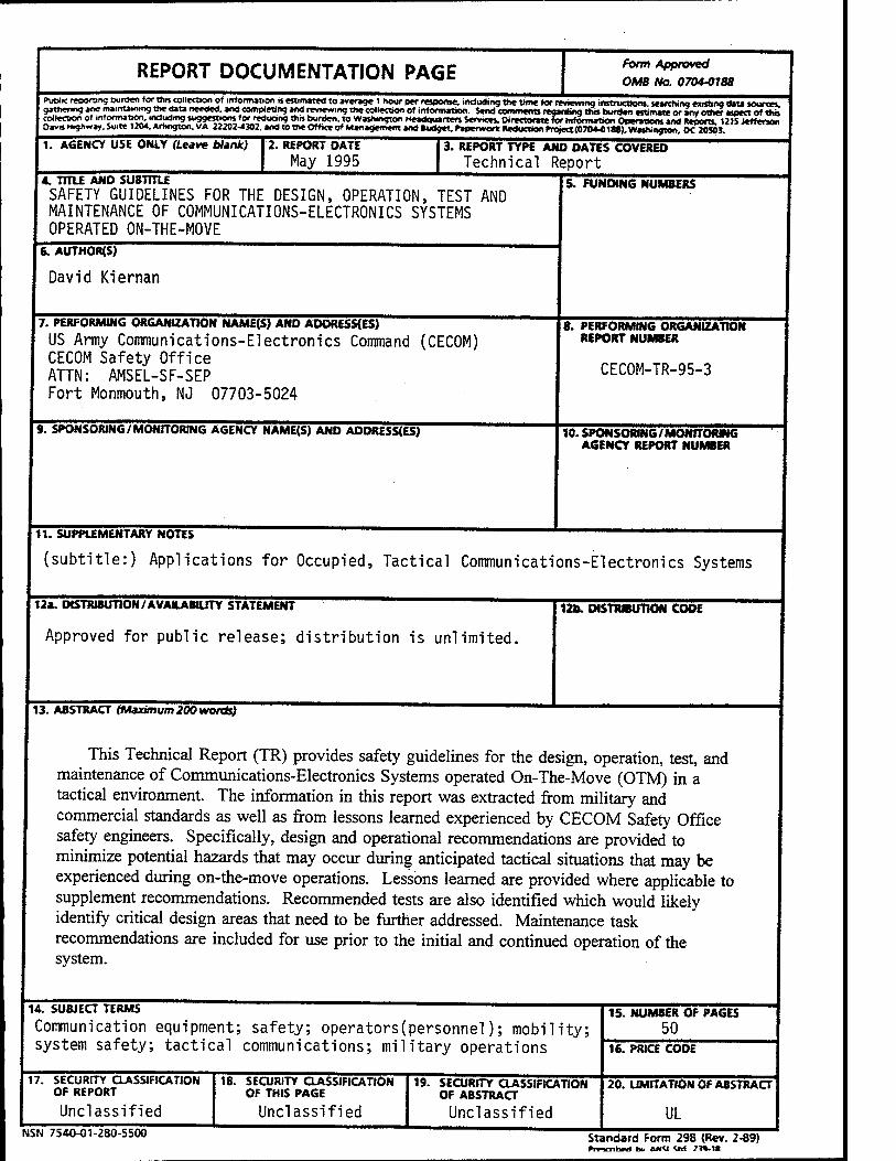
Technical Report CECOM-TR-95-3
Safety Guidelines for the Design, Operation, Test and Maintenance of Communications-Electronics Systems Operated On-The-Move
Applications for Occupied, Tactical Communications-Electronics Systems
David Kiernan CECOM Safety Office
May 1995
DTIC ELECTE JUt 1 8 1995
DISTRIBUTION STATEMENT: Approved for public release;
distribution is unlimited.
Dili QUALITY INSPECTED 5
CECOM Ü.S. ARMY COMMUNICATIONS-ELECTRONICS COMMAND CECOM SAFETY OFFICE, ATTN: AMSEL-SF-SEP FORT MONMOUTH, NEW JERSEY 07703-5024
19950710 025
NOTICES
Disclaimers
The findings in this report are not to be construed as an official Department of the Army position, unless so desig- nated by other authorized documents.
The citation of trade names and names of manufacturers in this report is not to be construed as official Government endorsement or approval of commercial products or services referenced herein.
REPORT DOCUMENTATION PAGE Form Approved
OMB No. 07044188
Put*« mxxting Durden Icow collection of mtormaLon n est.mated to average I »our ptr response, .ndudtng the time for revwvrmg .nstrucoons. search.ng existing UU sources, gathering ana manuaimng the data needed, and completing and reviewing the collection of information. Send comments regarding tha burden estimate or any other aspect of thb collection of mtormaiso^ .ndudrng suggestions for.reduang th» burden, to Washington Headquarters Services. Directorate for information Operations and Reports. 12tSJ«ffenon OavaM.ghv.ay.Su.te 1204. Arlington. VA Z2202-4X2. and to the Office of Management and Budget. Paperwork l^ucticwrYoyeaCOTO^Iaffwashmg^oTSsoa
1. AGENCY USE ONLY (Leave blink) 2. REPORT DATE
May 1995 3. REPORT TYPE AND OATES COVERED
Technical Report 4. TITLE AND SUBTITLE SAFETY GUIDELINES FOR THE DESIGN, OPERATION, TEST AND MAINTENANCE OF COMMUNICATIONS-ELECTRONICS SYSTEMS OPERATED ON-THE-MOVE
6. AUTHORS)
David Kiernan
7. PERFORMING ORGANIZATION NAME(S) AND ADDRESSES)
US Army Communications-Electronics Command (CECOM) CECOM Safety Office ATTN: AMSEL-SF-SEP Fort Monmouth, NJ 07703-5024
5. FUNDING NUMBERS
9. SPONSORING/MONITORING AGENCY NAME(S) AND ADDRESSES)
8. PERFORMING ORGANIZATION REPORT NUMBER
CECOM-TR-95-3
10. SPONSORING/MONITORMG AGENCY REPORT NUMBER
11. SUPPLEMENTARY NOTES
(subtitle:) Applications for Occupied, Tactical Communications-Electronics Systems
12a. DISTRIBUTION/AVAILABUJTY STATEMENT
Approved for public release; distribution is unlimited.
13. ABSTRACT (Maximum 200 words)
12b. DISTRIBUTION CODE
This Technical Report (TR) provides safety guidelines for the design, operation, test, and maintenance of Communications-Electronics Systems operated On-The-Move (OTM) in a tactical environment. The information in this report was extracted from military and commercial standards as well as from lessons learned experienced by CECOM Safety Office safety engineers. Specifically, design and operational recommendations are provided to minimize potential hazards that may occur during anticipated tactical situations that may be experienced during on-the-move operations. Lessons learned are provided where applicable to supplement recommendations. Recommended tests are also identified which would likely identify critical design areas that need to be further addressed. Maintenance task recommendations are included for use prior to the initial and continued operation of the system.
14. SUBJECT TERMS ~~""~"~—"~—"""
Communication equipment; safety; operators(personnel); mobility; system safety; tactical communications; military operations
17. SECURITY CLASSIFICATION OF REPORT
Unclassified NSN 754O-01-280-S500
18. SECURITY CLASSIFICATION OF THIS PAGE
Unclassified
19. SECURITY CLASSIFICATION OF ABSTRACT
Unclassified
15. NUMBER OF PAGES 50
16. PRICE CODE
20. LIMITATION OF ABSTRACT
UL Standard Form 298 {Rev. 2-89) Prrvnlnt hv AMU «d 71». t«
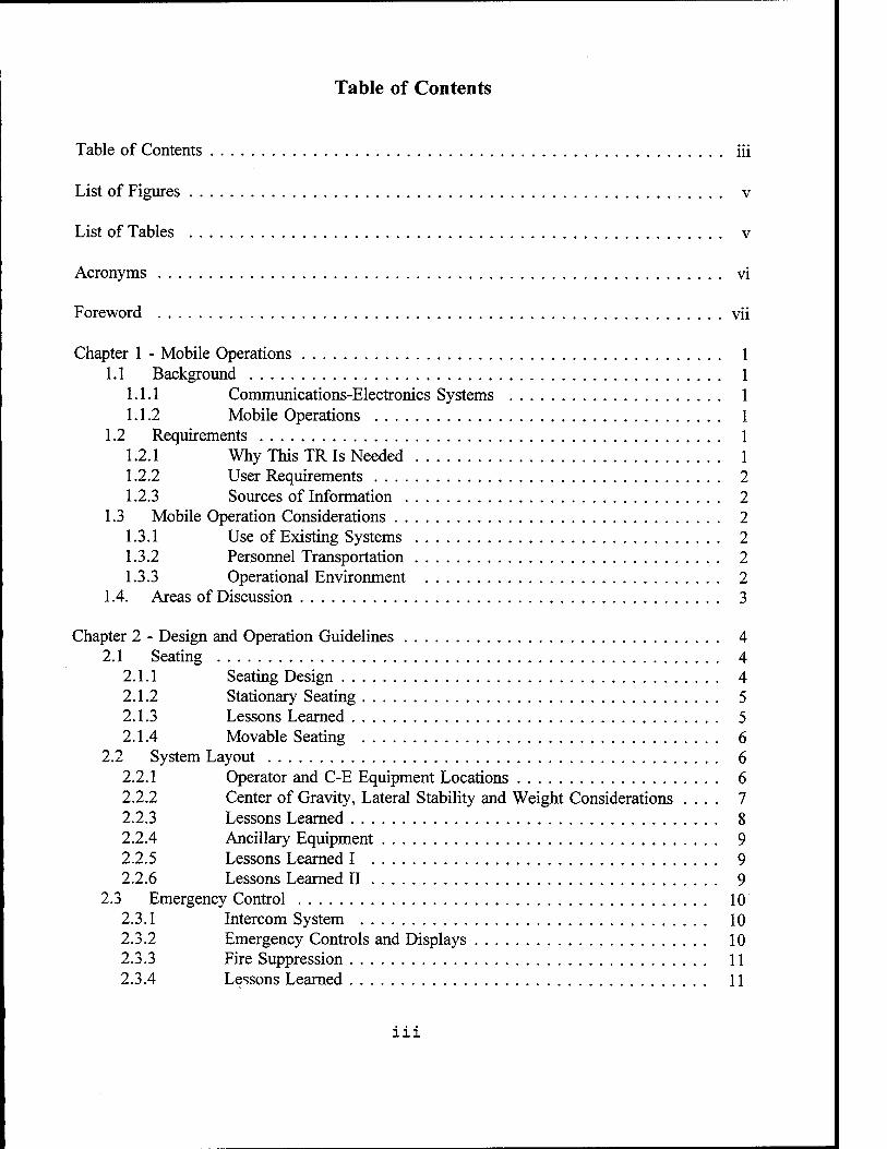
Table of Contents
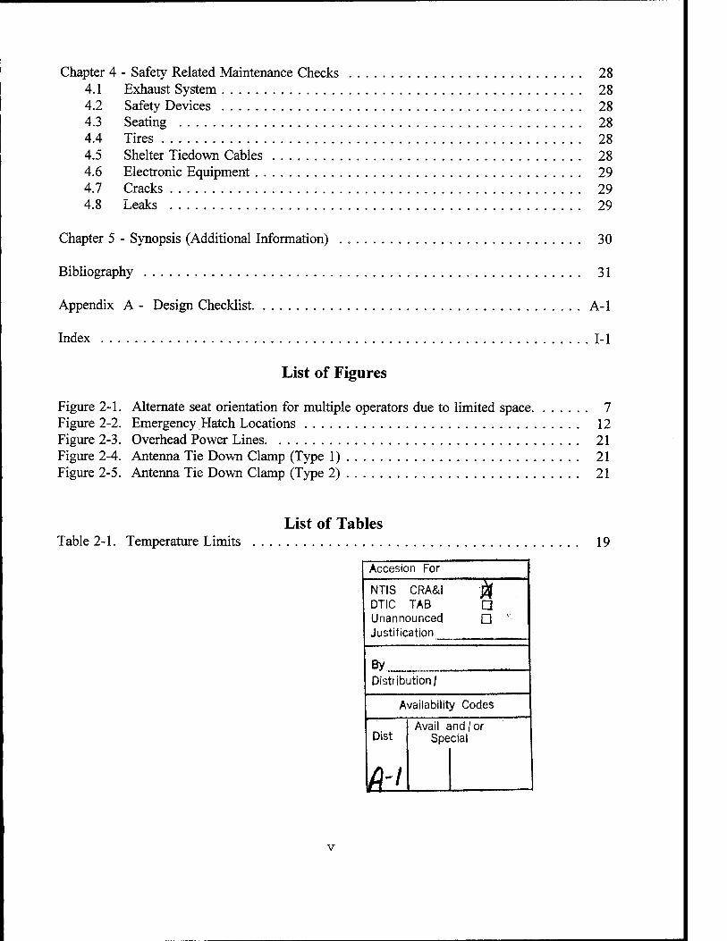
Table of Contents iii
List of Figures v
List of Tables v
Acronyms vi
Foreword vii
Chapter 1 - Mobile Operations 1.1 Background
1.1.1 Communications-Electronics Systems 1.1.2 Mobile Operations
1.2 Requirements 1.2.1 Why This TR Is Needed 1.2.2 User Requirements 2 1.2.3 Sources of Information 2
1.3 Mobile Operation Considerations 2 1.3.1 Use of Existing Systems 2 1.3.2 Personnel Transportation 2 1.3.3 Operational Environment 2
1.4. Areas of Discussion 3
Chapter 2 - Design and Operation Guidelines 4 2.1 Seating 4
2.1.1 Seating Design 4 2.1.2 Stationary Seating 5 2.1.3 Lessons Learned 5 2.1.4 Movable Seating 6
2.2 System Layout 6 2.2.1 Operator and C-E Equipment Locations 6 2.2.2 Center of Gravity, Lateral Stability and Weight Considerations .... 7 2.2.3 Lessons Learned 8 2.2.4 Ancillary Equipment 9 2.2.5 Lessons Learned I 9 2.2.6 Lessons Learned II 9
2.3 Emergency Control 10 2.3.1 Intercom System 10 2.3.2 Emergency Controls and Displays 10 2.3.3 Fire Suppression 11 2.3.4 Lessons Learned 11
in
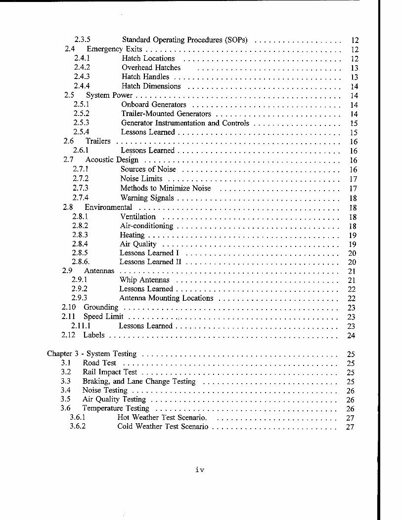
2.3.5 Standard Operating Procedures (SOPs) 12 2.4 Emergency Exits 12
2.4.1 Hatch Locations 12 2.4.2 Overhead Hatches 13 2.4.3 Hatch Handles 13 2.4.4 Hatch Dimensions 14
2.5 System Power 14 2.5.1 Onboard Generators 14 2.5.2 Trailer-Mounted Generators 14 2.5.3 Generator Instrumentation and Controls 15 2.5.4 Lessons Learned 15
2.6 Trailers 16 2.6.1 Lessons Learned 16
2.7 Acoustic Design 16 2.7.1 Sources of Noise 16 2.7.2 Noise Limits 17 2.7.3 Methods to Minimize Noise 17 2.7.4 Warning Signals 18
2.8 Environmental 18 2.8.1 Ventilation 18 2.8.2 Air-conditioning 18 2.8.3 Heating 19 2.8.4 Air Quality . 19 2.8.5 Lessons Learned I 20 2.8.6. Lessons Learned II 20
2.9 Antennas 21 2.9.1 Whip Antennas 21 2.9.2 Lessons Learned 22 2.9.3 Antenna Mounting Locations 22
2.10 Grounding 23 2.11 Speed Limit 23
2.11.1 Lessons Learned 23 2.12 Labels 24
Chapter 3 - System Testing 25 3.1 Road Test 25 3.2 Rail Impact Test 25 3.3 Braking, and Lane Change Testing 25 3.4 Noise Testing 26 3.5 Air Quality Testing 26 3.6 Temperature Testing 26
3.6.1 Hot Weather Test Scenario 27 3.6.2 Cold Weather Test Scenario 27
IV
Chapter 4 - Safety Related Maintenance Checks 28 4.1 Exhaust System 28 4.2 Safety Devices 28 4.3 Seating 28 4.4 Tires 28 4.5 Shelter Tiedown Cables 28 4.6 Electronic Equipment 29 4.7 Cracks 29 4.8 Leaks 29
Chapter 5 - Synopsis (Additional Information) . 30
Bibliography 31
Appendix A - Design Checklist A-l
Index 1-1
List of Figures
Figure 2-1. Alternate seat orientation for multiple operators due to limited space 7 Figure 2-2. Emergency Hatch Locations 12 Figure 2-3. Overhead Power Lines. 21 Figure 2-4. Antenna Tie Down Clamp (Type 1) 21 Figure 2-5. Antenna Tie Down Clamp (Type 2) 21
List of Tables Table 2-1. Temperature Limits 19
Accesion For
NTIS CRA&i DTIC TAB Unannounced Justification
□
By Distribution/
Availability Codes
Dist
m Avail and /or
Special
v
Acronyms
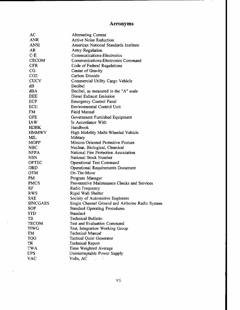
AC ANR ANSI AR C-E CECOM CFR CG C02 CUCV dB dBA DEE ECP ECU FM GFE IAW HDBK HMMWV MIL MOPP NBC NFPA NSN OPTEC ORE) OTM PM PMCS RF RWS SAE SINCGARS SOP STD TB TECOM TIWG TM TQG TR TWA UPS VAC
Alternating Current Active Noise Reduction American National Standards Institute Army Regulation Communications-Electronics Communications-Electronics Command Code of Federal Regulations Center of Gravity Carbon Dioxide Commercial Utility Cargo Vehicle Decibel Decibel, as measured in the "A" scale Diesel Exhaust Emission Emergency Control Panel Environmental Control Unit Field Manual Government Furnished Equipment In Accordance With Handbook High Mobility Multi-Wheeled Vehicle Military Mission Oriented Protective Posture Nuclear, Biological, Chemical National Fire Protection Association National Stock Number Operational Test Command Operational Requirements Document On-The-Move Program Manager Preventative Maintenance Checks and Services Radio Frequency Rigid Wall Shelter Society of Automotive Engineers Single Channel Ground and Airborne Radio System Standard Operating Procedures Standard Technical Bulletin Test and Evaluation Command Test, Integration Working Group Technical Manual Tactical Quiet Generator Technical Report Time Weighted Average Uninterruptable Power Supply Volts, AC . • '-
VI
Foreword
The information in this TR is presented in several chapters which are arranged to facilitate use of the TR. Chapter 1 describes the background and requirements of these mobile systems, in addition to a summary of the topics to be further discussed in the TR. Chapter 2 provides specific safety design guidelines and recommendations. Chapter 3 provides testing recommendations to verify that the system has been designed for safe mobile operations. Chapter 4 identifies specific maintenance tasks that may be required to ensure the safe condition of the system prior to mobile operation. The synopsis of this TR is provided in Chapter 5. A design checklist is provided in the Appendix.
VI1
Chapter 1 - Mobile Operations
1.1 Background
1.1.1 Communications-Electronics Systems
An entire tactical Communications-Electronics (C-E) system cannot, in general, be housed solely in conventional ground vehicles (i.e., Commercial Utility Cargo Vehicles (CUCV), High Mobility Multi Wheeled Vehicles (HMMWV), etc.) due to their space limitations. Therefore, complete systems are more readily housed in transportable shelters. Depending on the quantity and weight of the equipment, different size shelters and prime movers are available for use. However, the use of specific vehicles will be dictated by the user, as outlined in the Operational Requirements Document (ORD).
1.1.2 Mobile Operations
Until recently, shelterized C-E systems have primarily been operated when stationary. However, as the need for continuous communications on the battlefield increases, On-The- Move (OTM) operations of these systems will become more essential. All systems that will be used for OTM operations must be designed for such operation, and evaluated and tested following the recommendations of the Test Integration Working Group (TIWG), and guidelines contained in this TR. Any potential hazards identified as a result of the testing and evaluation must then be evaluated by the appropriate program manager In Accordance With (IAW) AR-385-16 to determine if the system is acceptable for mobile operations or if modification is required.1
1.2 Requirements
1.2.1 Why This TR Is Needed
This TR provides the necessary safety guidelines for the design, operation, test and maintenance of C-E systems that will be occupied by personnel during OTM operations. However, the incorporation of the recommendations provided in this TR will reduce but may not eliminate some of the discomforts or hazards to personnel.
Design guidelines address both newly developed systems and existing systems that may require modification to allow mobile operation. These guidelines can be applied to the design of C-E systems installed in shelters, HMMWVs, track vehicles, or other vehicles or enclosures that can be occupied by one or more soldiers during mobile operations.
xRef. 1, AR 385-16
1.2.2 User Requirements
Before a system can be designed, the user community must clearly define the soldier's tasks and related performance requirements that must be performed OTM, in order to satisfy operational and safety requirements. The Program Manager (PM) will evaluate these requirements and inform the users of any increased safety risks associated with OTM operation that cannot be designed out of the system. The users will then decide if OTM operations are acceptable for their mission.
1.2.3 Sources of Information
The information contained in this TR is derived from the sources identified in the bibliography and CECOM lessons learned, as experienced by CECOM Safety Office safety engineers.
1.3 Mobile Operation Considerations
1.3.1 Use of Existing Systems
It is important to note that existing communications systems may not have been designed to provide adequate protection to personnel occupying these shelters during mobile operation. OTM operation of systems not designed for such operation may cause serious personal injury or death. Therefore, these systems must be tested to determine acceptability of mobile operations or if modification is required.
1.3.2 Personnel Transportation
To minimize injury, personnel should only be transported inside shelters when such action is mission essential for operation of the system. Remote operation of the C-E system from the vehicle cab should be considered when extensive modifications to the shelter would be required to allow transportation of personnel. Also, from the soldier's perspective, being transported inside a confined space, such as a shelter, is less desirable than in a typical vehicle due to a higher likelihood of motion sickness and fatigue. The severity of these will depend on several factors such as the size of the shelter, type of work being performed, vibration levels operators are subjected to, amount of ventilation, heat and cold stress, operator orientation (e.g., person not sitting in the direction of travel), and lack of external visual references (e.g., no windows).
1.3.3 Operational Environment
The system must be designed to provide maximum personnel and equipment protection for operation under all environmental conditions (i.e., arctic or desert) required by the user. However, it is recommended that the system be designed for all conditions which could be experienced in a tactical situation to provide the user with a more versatile system which may be required in the future.
1.4. Areas of Discussion
The following topics are discussed in detail in this TR:
• Seating. The type of seating that should be used in a mobile shelter.
• System Layout. How equipment layout and operator location within the shelter can affect personal safety and overall safety of the system.
• Emergency Control. What should be used to control emergency situations in a shelter during mobile operations.
• Emergency Exits. Why two separated emergency exits should be incorporated.
• System Power. Sources of power used with mobile shelters.
• Trailers. Precautions to minimize hazards when pulling generators behind the shelter.
• Acoustic Design. How to control hazardous noise that may exist within the shelter and vehicle cab to prevent hearing damage.
• Environmental. How to provide the operator with a safe and comfortable work environment.
• Antennas. How to prevent and protect the shelter and operators from contact with overhead power lines.
• Grounding. Why earth grounding is only necessary during stationary operation.
• Speed Restrictions. Why speed limits may not always be acceptable.
• Labels. When caution labels are required.
• Testing. What testing should be performed to determine if the system will be safe for OTM operations.
• Maintenance. What maintenance procedures must be performed prior to OTM operations.
Chapter 2 - Design and Operation Guidelines
The design and operational guidelines of mobile, shelterized C-E systems are presented in this chapter.
2.1 Seating
Properly designed seating will minimize potential injury that is possible during mobile operation. Seating design must take into consideration the operation of the system during all possible conditions of travel, such as operation on primary and secondary roads, and events such as sudden braking, turning, and collision. During mobile operation, riding personnel must not be required to leave their seats since injury may result from being bounced about the shelter. For example, personnel may be thrown into equipment or other occupants during sudden stopping, acceleration, or motor vehicle accidents. This requirement must be trained to shelter occupants and addressed in Technical Manuals (TMs) and Standard Operating Procedures (SOPs).
2.1.1 Seating Design
The dimensions and adjustments for the design of seating should be in accordance with SAE J899. Seating must also comply with the following:
• Incorporate a five point, adjustable and quick-release harness to secure the operator to the seat. The harness must not interfere with or entangle the operator during emergency egress from the shelter. The harness must also accommodate all percentile of users.
• Incorporate adjustable head rests and arm rests. Headrests and arm rests must be usable by all percentile of the user population to prevent neck injury, reduce effects of motion sickness, and to provide the greatest comfort.
• Incorporate a high seat back. The use of high back seats will minimize back and neck injury that would likely occur with low back seats and the five point harness restraint system during sudden braking, acceleration, and/or motor vehicle accidents.
• Have adequate seat padding. Padding must keep the operator's body from hitting the seat frame during mobile operation.2 The seat must also withstand personnel from stepping on it to access the emergency hatch and to exit the shelter through the hatch.
• Orient the operator towards (or opposite) the direction of travel as much as possible. Operators facing forward or backwards will be less likely to receive neck injury/strain associated with the side-to-side head and body motion that will exist when facing the side
2Ref. 2, MIL-STD-1472D, Paragraph 5.12.2.6.
4

walls of a mobile shelter. In addition, motion sickness may be less severe. It is likely that neck injury/strain will be compounded by operation of the shelter over poor roads, sudden stopping, quick acceleration, and improperly isolated seating.
• A lock to prevent unintended rotation/movement.
• Seats and arm rests must not obstruct personnel from exiting the shelter in emergency situations.
• Seats must be securely mounted on the shelter floor and tested.
• Depending on the size of the shelter, it may be necessary to temporarily remove the seat for equipment installation, removal, and maintenance.
• Must allow personnel wearing arctic or Mission Oriented Protective Posture (MOPP) gear to sit comfortably and safely and quickly egress from the shelter.
In addition to the above requirements, the seat should be adjustable with respect to height, fore/aft direction, and angle of seat back (e.g., reclining) for human factor considerations.
2.1.2 Stationary Seating
Stationary seating is the preferred seating arrangement in mobile shelters in which all equipment to be operated can be safely reached by a fixed operator. Stationary seats should rotate and swivel for maximum equipment access, comfort and ease of entry and exit. Movable seating should be considered if not all equipment can be placed within reach of the fixed operator.
2.1.3 Lessons Learned
During the development of the Rigid Wall Shelter (RWS) it was found that seating restraint hardware (e.g., eyebolts) was mounted on the ceiling and floor near the exit. Since these shelters have low ceilings, personnel leaving their seats in an emergency situation, to exit the shelter, would likely bump their heads on the eye bolts causing injury. In addition, personnel could trip on the floor mounted hardware and fall out of the shelter and onto the ground.
Early in the system design phase, head bumping, tripping hazards, and protrusions into the aisle must be minimized to prevent injury and to allow unimpeded emergency egress from the shelter.
2.1.4 Movable Seating
Since personnel are not permitted to leave their seats during OTM operations, movable seating would allow access to all necessary C-E equipment that could not be reached when seated in a stationary seat.
Movable seating may be achieved by utilizing seats that slide on tracks on the shelter floor. The track seating system:
• Must not present tripping hazards. Recessed tracks should be used to minimize tripping hazards.
• Must allow the seat to automatically lock in place when the locking mechanism is released by the seated occupant. This will reduce the possibility of injury during accidents or unexpected stopping and acceleration. An inertial type of locking mechanism, to allow more freedom of movement within the shelter, may be desirable. This mechanism would not require the operator to disengage the locking mechanism each time movement about the shelter is required while automatically engaging during accidents or sudden/abnormal braking.
• Must be tested as required in chapter 3 to ensure that the seating can withstand the forces experienced during OTM operations.
When movable seating is employed, the use of radio headsets should be considered to eliminate entanglement of the wiring with the operator. However, Radio Frequency (RF) interference with other equipment and systems must be evaluated.
2.2 System Layout
Guidelines are presented in this section for system layout considerations and how the Center of Gravity (CG), lateral stability, and loading of the shelter are effected. Equipment and operator locations within a mobile shelter must be based on such aspects as the necessary orientation of the operator to the equipment for ease of use and safety, size of controls and displays, and the amount of time each equipment is to be operated during mobile operation.
2.2.1 Operator and C-E Equipment Locations
All equipment must be oriented such that the operators will face forward to the greatest extent possible and not perpendicular to the direction of travel, to minimize injury and side effects of motion, such as motion sickness. The system must be evaluated/tested to determine the acceptability of seat orientation with respect to mission performance (i.e., minimize motion sickness) and ease of egress from the seating and shelter.
A wraparound console containing all equipment to be operated during OTM operations, facing forward or backward to the direction of travel, should be considered to minimize seat
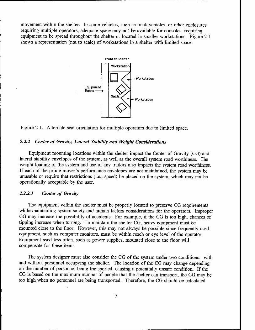
movement within the shelter. In some vehicles, such as track vehicles, or other enclosures requiring multiple operators, adequate space may not be available for consoles, requiring equipment to be spread throughout the shelter or located in smaller workstations. Figure 2-1 shows a representation (not to scale) of workstations in a shelter with limited space.
Front of Shelter
Equipment Racks
Workstation
Workstation
Figure 2-1. Alternate seat orientation for multiple operators due to limited space.
2.2.2 Center of Gravity, Lateral Stability and Weight Considerations
Equipment mounting locations within the shelter impact the Center of Gravity (CG) and lateral stability envelopes of the system, as well as the overall system road worthiness. The weight loading of the system and use of any trailers also impacts the system road worthiness. If each of the prime mover's performance envelopes are not maintained, the system may be unusable or require that restrictions (i.e., speed) be placed on the system, which may not be operationally acceptable by the user.
2.2.2.1 Center of Gravity
The equipment within the shelter must be properly located to preserve CG requirements while maintaining system safety and human factors considerations for the operators. Improper CG may increase the possibility of accidents. For example, if the CG is too high, chances of tipping increase when turning. To maintain the shelter CG, heavy equipment must be mounted close to the floor. However, this may not always be possible since frequently used equipment, such as computer monitors, must be within reach or eye level of the operator. Equipment used less often, such as power supplies, mounted close to the floor will compensate for these items.
The system designer must also consider the CG of the system under two conditions: with and without personnel occupying the shelter. The location of the CG may change depending on the number of personnel being transported, causing a potentially unsafe condition. If the CG is based on the maximum number of people that the shelter can transport, the CG may be too high when no personnel are being transported. Therefore, the CG should be calculated
without personnel occupying the shelter, minimizing the need for counterpoises. Testing or analysis must be performed to verify proper CG under both scenarios.
2.2.2.2 Lateral Stability
Equipment weight must be distributed evenly between the road and curbside walls of the shelter to maintain the lateral stability. As with improper CG, accidents are more likely to occur in shelters in which the lateral stability is not maintained. The lateral stability of the shelter must also be considered with and without personnel being transported. The system must be designed so that operator seats are situated in the middle of the shelter so that one side of the shelter will not be loaded down when carrying the maximum number of occupants.
Testing or analysis is required for verification of proper weight distribution before OTM operations are permitted. If it is determined that the shelter is not properly balanced, restrictions (i.e., speed or slope) will be required or equipment must be relocated. The latter choice is recommended since restrictions cannot always be adhered to during a wartime environment. Also, the use of counterpoises should be avoided to minimize possible overweight conditions and the resultant limitations on additional cargo or equipment that can be stowed in the shelter. Therefore, it is necessary to carefully plan equipment layout early in the design process to minimize costly modifications which may be required following testing.
2.2.2.3 Weight
Systems weighing in excess of the prime mover's maximum payload may cause potentially hazardous conditions due to possible brake, engine, tire, and suspension failure. The maximum allowable payload of the shelter's prime mover shall include the weight of the shelter and all items installed or stored in the shelter, trailer tongue weight, the weight of the crew plus personal equipment, and spare fuel and water cans. If the vehicle's payload is exceeded, restrictions may then be required as determined through system testing.
2.2.3 Lessons Learned
During a system design review, it was determined that the curbside of the shelter was 350 pounds greater than the roadside. Left uncorrected, a potential safety hazard could exist during OTM operations.
The contractor did not evaluate the lateral stability of the shelter until after all the equipment was installed. To correct the problem, the contractor proposed adding a 150- pound counterpoise to the roadside of the shelter. This proposal was rejected since the weight of the system would be increased to the maximum limit, which would limit the amount of extra equipment that could be carried in the shelter. The contractor was required to rearrange the equipment within the shelter, which impacted the program schedule and budget.
To minimize costly redesign, the CG, lateral stability, and weight considerations must be evaluated throughout the design process and corrected as required. The system must also be
designed to allow the soldiers to carry additional gear that may be required to sustain operations during a wartime environment.
2.2.4 Ancillary Equipment
Ancillary equipment such as ground rods, antennas, technical manuals, firearms, transit/transport cases, ladders, personal gear, etc. must be securely mounted prior to mobile operations. It is recommended that ladders be mounted on the outside wall of the shelter near the main entrance. These items must not block access to safety equipment or aisle way leading to the exits. No equipment shall be stowed between the shelter exit and vehicle tailgate or on top of the roof or roof emergency hatch which would obstruct personnel from exiting the shelter in an emergency situation. In addition, the tailgate must be removed if it obstructs the main entrance or presents a tripping hazard. Fuel cans or hazardous chemicals must always be stowed outside the shelter during OTM operations to minimize spillage and subsequent exposure to shelter occupants. These requirements must be identified in system Technical Manuals and trained to operators.
2.2.5 Lessons Learned I
During operational testing of a mobile communications system utilizing an S-280 shelter, an accident occurred due to the inadequate mounting of antenna mast sections inside the shelter. The mast sections were stowed above C-E equipment racks and secured in place using adjustable tiedown straps. During mobile operation, several mast sections fell off the mounting shelf, with one hitting the operator's head. No injuries were sustained since the required head protection was used.
A safety evaluation concluded that the tiedown straps were installed incorrectly, allowing the straps to loosen during mobile operation. In addition to using easy to install tiedown straps, a redundant safety measure should be incorporated to further prevent this type of accident from occurring. For example, safety netting could be used to prevent any loose mast sections from falling out of the storage area.
This accident shows why helmets must always be worn by shelter occupants and that nothing can be left loose during OTM operations. In addition, testing (IAW chapter 3) must be performed to verify that equipment mountings and tiedowns can withstand an impact without dislodging.
2.2.6 Lessons Learned II
Prior to OTM operations of a C-E shelter, an aluminum cooking pan was left unsecured on top of a battery compartment. During shelter movement the pan fell between the shelter wall and the battery box, contacting the exposed battery terminals and creating a short circuit, causing damage to the battery and the shelter.
The unprotected battery terminals also presented a safety hazard to personnel who could reach behind the battery compartment. To avoid equipment damage and personal injury, all battery terminals must be provided with protective covers and all loose equipment secured.
2.3 Emergency Control
The requirement for constant communications between shelter occupants and vehicle driver, as well as the necessary emergency control guidelines for use during OTM operations, are presented in this section.
2.3.1 Intercom System
An intercom system between the vehicle driver and shelter occupants must be provided for constant communications during OTM operations and for emergency situations. The intercom will allow the shelter occupants to alert the vehicle driver of any emergency situations that may occur within the shelter or external to the shelter of which the driver may be unaware, and vice versa. The use of Active Noise Reduction (ANR) headsets should be considered to filter out noise within the shelter while allowing clear communications. ANR headsets should also be considered for use by vehicle drivers who may be exposed to excessive engine noise (i.e., operation of the HMMWV above 25 mph).
2.3.2 Emergency Controls and Displays
It is recommended that an Emergency Control Panel (ECP), located in both the vehicle cab and shelter, be provided as a backup to the intercom system. The ECP would be used to warn personnel of hazardous conditions which may be either life threatening or capable of causing system loss. Situations such as equipment overtemperature conditions, fire, power shutdown, or a Nuclear, Biological, or Chemical (NBC) event would be indicated on the panel and punctuated with an audio alarm.
The ECP in the shelter would alert shelter occupants of emergencies external to the shelter which have been identified by cab occupants or external sensors. The ECP in the cab would alert cab occupants of emergencies within the shelter or situations external to the vehicle.
All emergency controls and displays in the shelter should be physically grouped together on the ECP and separated from noncritical controls and indicators. The ECP must be located near the operator's main workstation at eye level to allow the operator to quickly focus attention in only one area and to allow a quicker response than if the controls/displays were spread throughout the work area.
During mobile operation, controls may be difficult for the operator to use due to road vibrations and bouncing that will be encountered. Therefore, it is recommended that emergency controls be enlarged to provide a better grip. Controls should be located such that they will not be inadvertently actuated. If a control must be located where it is likely to be
10
hit or brushed against, inherently "bump" resistant controls (e.g., rotary switches, locking toggle switches, recessed pushbuttons, etc.) should be used. Guards should always be avoided on emergency controls since they may impede their use.
Visual warnings (e.g., red lamp) may be effective in noisy environments but may not be practical if they are outside the operator's field of view. Therefore, audio warnings will likely be more effective in systems that require high operator concentration. Audio warning signals must always be perceivable by operators who may be wearing headsets.
2.3.3 Fire Suppression
Fire extinguishers must always be within reach of the seated operator. If space exists, the extinguisher should be mounted under or behind each operator's seat and be easily reached in an emergency. If a fire extinguisher cannot be mounted to the operator's seat, then two fire extinguishers are required in large shelters, such as the S-280. One extinguisher must be located near the front of the shelter and the other near the exit. The front fire extinguisher would allow an operator seated in front of the shelter to fight a fire anywhere in the shelter, particularly a fire blocking the exit. The rear fire extinguisher would allow an operator seated in the rear (or located outside) of the shelter to fight a fire in the front of the shelter without passing through the fire to access the front fire extinguisher. One fire extinguisher will be required in smaller shelters (e.g., S-250), mounted as close to the exit as possible, and within reach of the seated operator.
The use of Carbon Dioxide (C02) fire extinguishers can cause oxygen deprivation in confined spaces, such as shelters. If C02 extinguishers are used, the effects of its use must be identified in both training and in TMs. It is recommended that dry chemical fire extinguishers be used in this environment.
Fire axes should also be included and located near the shelter exit. Axes may aid in unblocking obstructed exits or emergency exits. These items must be located to allow for unimpeded removal and use.
2.3.4 Lessons Learned
During the development of the RWS, the fire extinguisher was found to obstruct the operator when exiting the shelter, as well as interfering with the installation and replacement of equipment in the racks.
To allow unobstructed emergency egress from the shelter the fire extinguisher was relocated to another readily accessible location. This new mounting location also eliminated the requirement to remove the fire extinguisher and brackets prior to equipment removal/replacement, which minimized their possible loss when removed.
11
2.3.5 Standard Operating Procedures (SOPs)
Personnel must be trained how to react to emergency situations that may occur during OTM operations. Therefore, SOP for emergencies must be developed and trained to the operators. The procedures need to provide the necessary steps to be taken to reduce equipment and shelter damage in addition to personal injury. The SOP must also provide instructions on the use of all control and display panels, including the interpretations of all indicators and alarms.
2.4 Emergency Exits
The incorporation of emergency hatches provides an alternate means of escape from the shelter when the main entrance is obstructed. Emergency exits shall not require a key or tool to open from the inside.3 In addition, all hatches must be illuminated during blackout conditions using backup batteries and labeled providing any necessary opening instructions. Hatches must remain closed during OTM operation to maintain system cooling and heat dissipation, prevent infiltration of Diesel Exhaust Emissions (DEE) and to maintain protection provided by the NBC filtration system. This precaution must be identified during training and in system TMs.
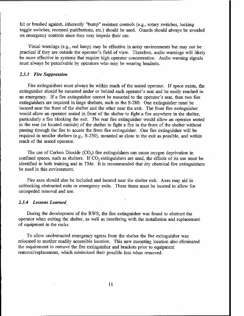
2.4.1 Hatch Locations
Many existing shelters utilize single escape hatches, incorporated on the main entrance. This emergency hatch is likely to be obstructed if the main entrance is blocked or damaged by a rear-end collision. Therefore, shelters operated OTM shall have two exits located remote from each other and so arranged as to provide unobstructed egress (see figure 2- 2).4 Limited space is available on shelter walls for a second emergency hatch, therefore, the second hatch can be located overhead.
Hatches must open out from the shelter, so that, in the event of
Generator Compartment
Power/Signal Entry Panel
Emergency Hatch
Figure 2-2. Emergency Hatch Locations
3Ref. 3, NFPA 501C, Paragraph 3-2.4
4Ref. 3, NFPA 501C, Paragraph 3-2.1,
12

an accident, any equipment within the shelter that becomes loose does not prevent the hatch from opening. In addition, door-mounted hatches must open with less than 20 pounds of force5.
Vehicles must not utilize raised tailgates during mobile operation which may obstruct personnel from safely exiting the shelter in an emergency. These tailgates must be removed from the vehicle, kept in the horizontal position, or modified (i.e., notched) to allow unobstructed opening of the door or emergency hatch when raised. Also, operators must be informed of any trip hazards that may exist when exiting the shelter in an emergency situation.
2.4.2 Overhead Hatches
The overhead hatch will provide an alternate means of escape if the rear of the shelter is blocked during an accident. If the shelter rolls over onto its roof, then the rear exit can be used. If both exits are blocked, the crew can use the axe to tear open a wall or the floor.
The overhead hatch must be designed to allow opening with less than 50 pounds of force and be easily opened in the dark6. In addition, these hatches should be located in the center of the shelter aisle, above a seat. The seat can be used as a step to allow easier emergency egress. Use of equipment racks as steps shall not be relied upon to exit through the overhead hatch since slipping and falling is possible which may impede emergency egress from the shelter.
Hinges should be incorporated to allow complete removal of the overhead hatch from the shelter in the event of blockage. For example, roof hatches could be slid to the right or left and then lifted entirely out of the shelter.
2.4.3 Hatch Handles
Handles on emergency exits must be visible under blackout conditions. Considerations must be made to prevent finger-pinching hazards when closing the hatches. Overhead hatch handles must be located such that head injuries will be minimized when walking inside the shelter (e.g., utilize recessed handles).
5 'Ref. 2, MIL-STD-1472D, Paragraph 5.7.8.2.
6Ref. 2, MIL-STD-1472D, Paragraph 5.7.8.2.
13
2.4.4 Hatch Dimensions
Emergency hatch dimensions are identified in MIL-STD-1472D, figure 37.7 The larger dimensions (i.e., "bulky" columns) should be used to allow personnel wearing arctic or MOPP gear to exit the shelter in an emergency situation.
2.5 System Power
The system should be designed to operate from vehicle power only, for weight, space, and safety considerations. However, if vehicle power (i.e., including the use of a larger capacity alternator) is inadequate to operate the entire system, the use of generators will be required. An onboard generator should be considered before using a trailer-mounted generator.
2.5.1 Onboard Generators
Onboard generators may be mounted on either the prime mover's bed (e.g., between the shelter and vehicle cab) or in an exterior shelter compartment (e.g., tunnel).
Generators must be located and mounted to minimize excessive noise and DEE in the shelter or vehicle. Sound insulation may be required around the generator compartment or between the generator and shelter/vehicle cab to reduce personnel exposure to noise.
Generator compartments must be vapor-tight to the shelter interior so that DEE will not be introduced into the shelter.8 Figure 2-2 shows a shelter with a tunnel in which a generator can be installed. Exhaust pipes must be located so that they do not allow exhaust into the shelter's Environmental Control Units (ECUs) or fan intakes.
2.5.2 Trailer-Mounted Generators
These generators can be operated either when towed behind the shelter for mobile operations or remoted for stationary operations.
Approval for mobile operation of the generators must be granted by the generator set's materiel developer since modifications or an alternate generator set may be required if damage could occur during OTM operations. For example, during operation over steep terrains engine lubrication may be interrupted causing engine failure.
Cable routing between the generator and the shelter must not introduce tripping hazards for personnel exiting the shelter. Excess cable must be minimized or contained on the
7Ref. 2, MIL-STD-1472, Page 164.
8Ref. 3, NFFA 501C, Paragraph 2-6.2.5
14
generator to reduce tripping hazards and obstructions to prime mover's tailgate and shelter's exit.
The generator trailer must not be overloaded and equipment must not be stowed on it which could interfere with the generator controls or hand brakes, or be located where combustion or electrical shorting is possible.
2.5.3 Generator Instrumentation and Controls
For systems utilizing onboard and trailer-mounted generators, the following must be provided:
• A generator instrumentation panel The panel would, as a minimum, indicate power on/off status, low fuel, oil pressure, and engine temperature.
• A manual generator shutdown within reach of the operator and collocated with the main system power switch.
• Automatic engine shutdown for low oil pressure or high operating temperatures. This should be incorporated if it may not be possible for the operator to continuously monitor the generator instrumentation panel. A battle short should be provided to override the automatic shutdown feature.
• An audio warning (e.g., buzzer/bell), with a visual cue, to inform operators of the loss of primary power, low oil pressure, and high operating temperature.
• Emergency backup power. Backup provided by an Uninterruptable Power Supply (UPS) will allow use of lights and radios, for a limited time, in the event of a power
failure.
2.5.4 Lessons Learned
In a system utilizing an S-280 shelter and a trailer-mounted generator, the interconnecting power cable (50 ft.) was routed such that personnel exiting the shelter would be required to cross the cables, causing a possible tripping hazard. The 50 ft. cable was required for stationary operation to remote the generator for operational and diesel exhaust considerations. For this system, the cable was rerouted to minimize the amount of cable exposed to personnel exiting the shelter.
In newly designed systems for OTM operations it is recommended that shelters be provided with a main entrance door that opens towards the power entrance panel as shown in figure 2-2. This will help to reduce the chances of tripping due to the generator power cable. However, this should only be incorporated if the door, when opened, will not damage the cables and connectors connected to the panel. It is also recommended that a shorter cable, specifically for mobile operations, be used.
15
2.6 Trailers
In addition to the use of generator-mounted trailers, cargo trailers may be utilized with the system. These trailers are primarily used to transport and/or store additional C-E or other equipment, such as tents, antenna masts, grounding systems, food, etc. The weight capacity of the trailer and towing limits of the prime mover must not be exceeded, as determined by the materiel developer, and shall be verified through testing. Safety chains must be provided to ensure that the trailer will not become separated from the vehicle during movement. If the trailer is overweight, speed limitations may be required which may not be operationally acceptable by the user.
2.6.1 Lessons Learned
During the use of a system consisting of a HMMWV, S-250 shelter, and a PU-753/G generator, it was found that the suspension and tires of the generator trailer began failing prematurely. An evaluation determined that the generator trailers were being overloaded beyond their design limits with personal gear, transport cases, fuel cans, etc. The suspension systems were bottoming out, causing damage to the springs and tires. The tires were rubbing against the trailer fenders.
To prevent damage from overloading, suffer springs were installed on the generator trailer. In addition, enlarged fuel tanks, which increase the operating time of the generators by 10 hours, eliminated the need for spare fuel cans.
Systems must be designed to prevent overloading which could contribute to equipment failure. Adequate space and weight must be allocated so that the soldier can carry what is needed into the field.
2.7 Acoustic Design
Prolonged unprotected exposure to hazardous noise levels may cause loss of hearing. The shelter must be designed to eliminate or reduce excessive noise levels that may reach the ears of occupants. Operational requirements (e.g., radio use, person-to-person speech) may require lower noise levels that are more stringent than that required for safety reasons.
2.7.1 Sources of Noise
Possible sources of steady state noise that exist within the shelter are vehicle engines, road noise from tires, onboard or trailer-mounted generators, shelter ECUs and ventilation fans, equipment rack blowers, vibrations, and from the C-E equipment (e.g., internal equipment cooling fans, printers, etc.). Noise will likely increase in intensity in the shelter as the vehicle engine and road speed increases. Impulsive noise (i.e., artillery fire) is not discussed in this TR since it is not as prevalent as steady state noise within C-E systems.
16
2.7.2 Noise Limits
Personnel exposure to noise levels exceeding an 8-hour Time Weighted Average (TWA) of 85 dBA is considered hazardous.9 Testing must be performed to verify conformance with this requirement as detailed in chapter 3.
Where it can be documented as being clearly beyond the state-of-the-art to reduce the noise below 85 dBA through design, hearing protection must be provided. ANR helmets/headsets should be incorporated to reduce the noise reaching the ear, while maintaining constant communications with the driver. The use of any new headset must be approved by the Army Surgeon General.
2.7.3 Methods to Minimize Noise
This section provides recommendations for controlling or eliminating excessive noise levels within communications shelters or vehicle cabs.
2.7.3.1 Noise From Diesel Engines
It must be noted that prime movers provided as Government Furnished Equipment (GFE) may subject drivers to hazardous noise levels when driven above certain speeds (i.e., HMMWV driven above 25 mph). Noise warnings will be identified in vehicle TMs and labels incorporated within the cab. If the use of hearing protection within the cab is required, ANR headsets should be utilized to allow constant communications with shelter occupants. It may also be desirable to reduce the noise within the vehicle's cab using sound attenuating insulation on the engine cover and/or fire wall. However, any changes must be coordinated with and approved by the vehicle developer.
In addition to the noise produced by the vehicle engine, personnel may be subjected to noise from generator engines. The two most common methods to reduce this noise is with the incorporation of sound reduction kits or use of Tactical Quiet Generators (TQG). Vibrations from onboard generators are another source of noise that should be minimized. It is recommended that low frequency shock isolators be incorporated between the generator and shelter/vehicle to minimize the vibration and resulting noise.
2.7.3.2 Road Noise
Road noise, from tires, is unlikely to be reduced at the source since specific tires may be required for safe operation of the vehicle. However, the vehicle developer should be consulted in the event replacement tires are available. To control road noise within the shelter, sound attenuating insulation may be required in the shelter walls and/or floors as determined through test.
9Ref. 4, 29 CFR 1910.95.
17
2.7.3.3 Equipment Noise
ECUs, ventilation fans, rack blowers, and C-E equipment may produce high noise levels at the operator workstations. This equipment should either be installed in sound-insulated racks or be replaced by lower noise producing equipment.
2.7.4 Warning Signals
Equipment caution signals must be 20 dB above the ambient noise within the shelter, and have the capability to be either automatically or manually shut off.10 In addition, when an operator is wearing a headset that covers both ears, emergency signals must be directed to the headsets and to the work area11.
2.8 Environmental
The shelter must maintain an interior temperature between 65 and 85°F to provide a safe and comfortable work environment. To meet this requirement, air-conditioning and heating may be required. In addition, air within the shelter must not cause any health hazards to occupants. Testing will be required to verify that adequate heating and cooling are provided, and that air contaminants will not be subjected to users, as detailed in chapter 3.
2.8.1 Ventilation
Ventilation of the shelter is required for fresh air circulation. The ventilation fan may be part of the ECU or a stand alone item. Fresh-air intakes must be located to minimize the introduction of contaminated air into the shelter. Of particular concern is the proximity of the intakes to the prime mover and generator exhaust pipes.
2.8.2 Air-conditioning
Due to the potential heat generated by equipment within the shelter and external environmental conditions, including solar loading (heating), internal shelter temperatures may exceed a safe or comfortable level. This heat may not be adequately reduced by using ventilation fans alone.
Prolonged exposure to high temperatures may cause health problems (e.g., heat stroke) to personnel. Table 2-1 identifies the maximum amount of time that a person can work safely for a given temperature (this is the Effective Temperature which considers air temperature, humidity, and air movement)12. The maximum temperature at which a person can work safely
10Ref. 2, MIL-STD-1472D, Paragraph 5.3.4.1.
lxRef. 2, MIL-STD-1472D, Paragraph 5.3.
12Ref. 5, MIL-HDBK-759A, Paragraph 3.2.
18
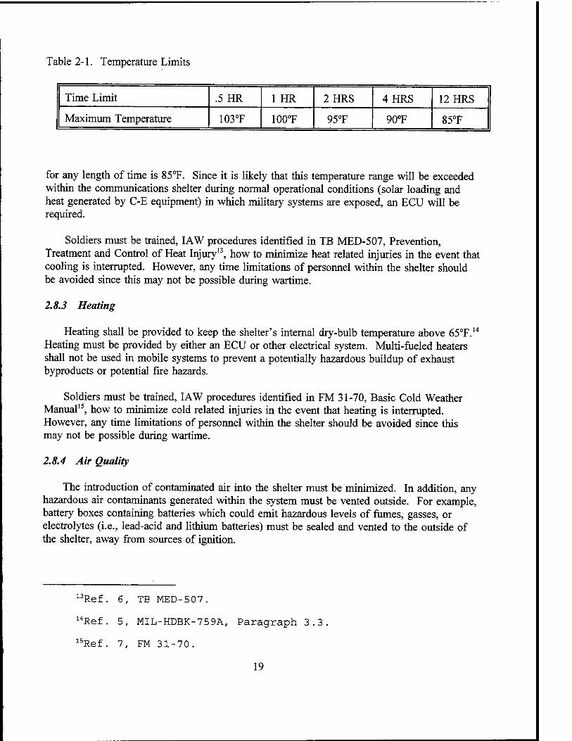
Table 2-1. Temperature Limits
Time Limit .5HR 1 HR 2HRS 4HRS 12HRS
Maximum Temperature 103T 100°F 95°F 90°F 85°F
for any length of time is 85°F. Since it is likely that this temperature range will be exceeded within the communications shelter during normal operational conditions (solar loading and heat generated by C-E equipment) in which military systems are exposed, an ECU will be required.
Soldiers must be trained, IAW procedures identified in TB MED-507, Prevention, Treatment and Control of Heat Injury13, how to minimize heat related injuries in the event that cooling is interrupted. However, any time limitations of personnel within the shelter should be avoided since this may not be possible during wartime.
2.8.3 Heating
Heating shall be provided to keep the shelter's internal dry-bulb temperature above 65°F.14
Heating must be provided by either an ECU or other electrical system. Multi-fueled heaters shall not be used in mobile systems to prevent a potentially hazardous buildup of exhaust byproducts or potential fire hazards.
Soldiers must be trained, IAW procedures identified in FM 31-70, Basic Cold Weather Manual15, how to minimize cold related injuries in the event that heating is interrupted. However, any time limitations of personnel within the shelter should be avoided since this may not be possible during wartime.
2.8.4 Air Quality
The introduction of contaminated air into the shelter must be minimized. In addition, any hazardous air contaminants generated within the system must be vented outside. For example, battery boxes containing batteries which could emit hazardous levels of fumes, gasses, or electrolytes (i.e., lead-acid and lithium batteries) must be sealed and vented to the outside of the shelter, away from sources of ignition.
13Ref. 6, TE MED-507.
14Ref. 5, MIL-HDBK-759A, Paragraph 3.3
15' Ref. 7, FM 31-70
19
2.8.5 Lessons Learned I
Additional equipment was added to an existing C-E system. The existing ECU did not have adequate cooling capacity to reduce the additional heat generated within the shelter. It was determined that personnel occupying the shelter could be subjected to potentially hazardous levels of heat under relatively mild, outside ambient temperatures.
The incorporation of a larger capacity ECU, or a second ECU, was not possible due to space and weight constraints. Several other options were considered to reduce the interior shelter temperature, but none (i.e., solar blanket, stand-alone ECU) could be used during OTM operations.
To minimize costly redesign, other equipment was removed, reducing the heat exposed to personnel and the functionality of the system. To maintain complete functionality, the shelter and/or prime mover would have to have been replaced. In new systems, it is recommended that the largest capacity ECU that can safely fit in a shelter be used to minimize costly redesign in the future.
2.8.6. Lessons Learned II
During operational testing of a C-E system in an S-280 shelter, carried by a 5-ton carrier, test personnel identified the presence of diesel exhaust within the shelter when the vehicle engine was running. Air sampling was subsequently performed to determine the source and concentration of DEE entering the shelter. It was determined that hazardous levels of DEE were entering the shelter through the ECU near the vehicle exhaust pipe. Further evaluation found that both ECU's fresh air vents were open and that the vehicle exhaust pipes were misaligned, directing exhaust toward the shelter.
Since a single ECU could provide adequate fresh air into the shelter, the curbside ECU fresh air vent was closed and air sampling was repeated. Air quality was then found to be acceptable. Subsequently, all of these shelter's curbside ECU fresh air vents were then closed, eliminating the hazard.
A costly redesign could have been required if it was determined that adequate levels of fresh air could not be provided in the shelter using one ECU, or that closing the fresh air vents could not prevent the DEE from entering the shelter.
The 5-ton vehicles that were being used were new. However, they were delivered with exhaust pipes pointing toward the shelter which contributed to the problem. It is therefore necessary to completely inspect the vehicle and shelter prior to operation and correct any hazardous conditions (see chapter 4).
20

2.9 Antennas
Mobile C-E systems must be designed to avoid contact with overhead obstacles such as power lines (see figure 2-3). It must be noted that high voltage power lines may be lower outside the U.S. (i.e., a height of 13 ft. in Germany).
2.9.1 Whip Antennas
DO NOT STOP YOUR VEHICLE UNDER POWER LINES
Figure 2-3. Overhead Power Lines.
During OTM operations, tie- down clamps (see figure 2-4 and 2-5) and ropes will be required to lower any whip antennas that could possibly strike overhead power lines or cause injuries to crewmembers or pedestrians when deflected. For maximum personnel protection, it is recommended that a two point tiedown assembly be used to minimize both the front-to-back and the side-to-side antenna movements. Antenna tip caps (NSN: 5895-00-930-7223) are required on the end of whip antennas to reduce the possibility of puncture wounds.16 For example, when antennas are tied down, personnel could inadvertently walk into the sharp ends, causing eye injuries.
Figure 2-4. Antenna Tie Down Clamp (Type 1)
Figure 2-5. Antenna Tie Down Clamp (Type 2)
Whenever mission permits, antennas which could come into contact with overhead power lines should be lowered prior to OTM operations. This would eliminate the need for the vehicle driver to stop each time a power line is encountered to determine if there is adequate clearance between the power line and the antenna. However, since the communication range of the system may be adversely impacted when the antennas are tied down, it is recommended that low profile antennas be used for OTM operations. Low profile antennas will minimize contact with overhead power lines, but may not protect crewmembers when the antennas are struck by other overhead obstacles, such as tree branches. For maximum personnel protection, antenna restraint boots should be incorporated to limit the forward rebound of the antenna
16 Ref. 8, TB 43-0129
21
after striking an obstacle. Hinged antenna mountings should be considered to lower antennas when constant communications during OTM operations is not required.
For maximum system protection from accidental contact with power lines or from a lightning strike, it is recommended that high voltage protection be integrated into the antennas (i.e., the SINCGARS AS-3900 whip antenna provides protection up to 20,000 VAC). However, in situations that permit, the antennas must always be lowered beneath power lines to minimize system damage or personal injury.
TMs, SOPs, and training must identify the vehicle profile and any requirements that the operators must follow to safely proceed beneath power lines. For example, operators must be instructed to lower antennas before passing under power lines if there is any doubt about overhead clearance and to turn off transmitters before handling antennas to attach tiedown ropes. Warning labels must be incorporated into vehicle cabs to remind the user of the tiedown requirement. In addition, the driver must be instructed to check that the system is not in contact with overhead power lines before allowing system operators to exit from the shelter.
2.9.2 Lessons Learned
A C-E system, with roof-mounted whip antennas, passed under and made contact with an overhead, high voltage power line. Since the antenna did not utilize high voltage protection, contact of the antenna with the power line caused extensive system damage.
Drivers must be trained to be alert to the dangers that may exist during OTM operations. They must ensure that antennas are tied down if there is any chance of contact with power lines. In addition, in the event that power lines are struck, personnel must not exit the shelter until contact with the power line is broken, to prevent electrical shock and death. The system SOP must address this concern. For example, before exiting the shelter, the driver should inform the shelter occupants that it is safe to proceed.
2.9.3 Antenna Mounting Locations
Antennas may have to be accessed for maintenance purposes and prior to traveling beneath power lines for attachment of tiedown ropes. Therefore, it is important to locate antennas where they are easily and safely reached by operators and/or maintainers, preferably without the use of a ladder.
Antennas should be mounted on a side wall or part of the shelter roof that is accessible by personnel standing on the vehicle tailgate or bed of the prime mover (e.g., between the cab and shelter). If a ladder is required, it is recommended that one ladder (i.e., adjustable) be used for both shelter and antenna access for weight and space constraints.
Antennas must also be located to minimize RF hazards to personnel during transmission. Antennas mounted near the shelter exit may effect personnel entering or exiting the shelter or
22
Standing on the vehicle tailgate. In addition, personnel standing near an open overhead hatch could also be exposed to dangerous levels of RF radiation. A label is required on hatches to warn personnel of any RF radiation hazards that may exist when the hatch is open. Since hatches must be closed prior to mobile operation this hazard would only occur during stationary operation.
If provisions to allow safe access to antennas are not provided, a permanently attached tiedown rope must be utilized. When the antennas are deployed, the rope must be secured so that it will not swing freely which could strike pedestrians, causing injury.
2.10 Grounding
Earth grounding of the system is only necessary during certain stationary modes of operation. For example, earth grounding is necessary when the system is interconnected with antenna masts, or other systems via field wire or other metallic cabling. Internal to the shelter, single point grounding (i.e., a single point in the system is designated as a ground reference point in which all ground connections are made17) must be employed. This method of grounding will provide a quick and reliable earth ground during stationary operation. Specific grounding requirements are identified in MIL-STD-1857, Grounding, Bonding, and Shielding Design Practices'8, which must be used during system design.
2.11 Speed Limit
The system must be designed to minimize speed restrictions due to the integration of the shelter on the prime mover. Speed restrictions could be required if the shelter performance envelopes (i.e., CG, weight, etc.) are not maintained, as determined through testing and analysis (see chapter 3). The possibility that the user will overload the system must be taken into consideration in determining any operational restrictions.
2.11.1 Lessons Learned
The use of vehicles with speed restrictions may present a hazardous condition when operated in a convoy of faster moving vehicles. Slower vehicles that ignore speed restrictions to keep up with the convoy may become unstable and crash, causing equipment damage and personal injury. Therefore, speed limitations of the prime mover, due to the integration of a shelter and trailer must always be avoided. However, any restrictions must be identified in system training, SOPs, TMs, and with a label in the vehicle cab, in addition to being approved by the user.
17Ref. 9, MIL-STD-1857, Paragraph 3.1.
18Ref. 9, MIL-STD-1857.
23

2.12 Labels
Caution and warning labels shall be incorporated in the shelter to inform the occupants of any hazardous conditions that could occur as a result of mobile operation. Label design, including size, color, and application requirements shall be in accordance with the American National Standard, ANSI Z535.4-1991, Product Safety Signs and Labels.19 Each equipment safety label must be identified in system TMs.
19Ref. 10, ANSI Z535.4-1991.
24
Chapter 3 - System Testing
This chapter summarizes tests that may be required by Army test agencies (e.g., Test and Evaluation Command (TECOM), Operational Test Command (OPTEC), etc.) and the TIWG to determine if the shelter will allow safe mobile operations while occupied. Test agencies will ensure that the necessary test plans have been developed for each system, and perform the testing.
3.1 Road Test
Road testing will help to determine the overall roadability of the system and suitability of the seating system. The typical road test area (i.e., Munson) consists of paved roads, improved gravel roads, sand course, abrasive mud course, Belgian block course, cross country, and other conditions (i.e., various terrain slopes and grades) that may be expected during normal mobile operation of a tactical system.
Testing will be performed at various vehicle speeds. Any trailers (e.g., generator) that are part of the system, must be towed behind the shelter during the test. Test dummies must be used and harnessed into the seats. It is recommended that a video camera be utilized within the shelter to monitor the test.
3.2 Rail Impact Test
This is a transportability test which subjects the system to severe impacts. Although personnel will not occupy a shelter during rail transport, this is an ideal test to simulate a collision and will help to determine if equipment and seating are adequately secured in the shelter. The entire system, including the prime mover and generator trailer, are placed on a flat bed railroad car. The flat bed car is towed and then released from the train, ramming into a fixed object. This test is performed several times at various speeds. A test dummy, appropriately weight-distributed for the 95th percentile male, must be harnessed into the seat to properly test the seat crash safety.
3.3 Braking, and Lane Change Testing
Testing must be performed to confirm braking of the vehicle is not degraded with the incorporation of the C-E system. In addition, lane change testing must be performed to verify proper CG and lateral stability. During testing, generators must be towed behind the shelter (as required to simulate actual operational scenarios), and test dummies strapped into the seats. If performance envelopes are not maintained, alternative vehicles may be required. For example, the heavy HMMWV variant has been designed to carry more weight than the standard HMMWV.
25
3.4 Noise Testing
Noise testing must be performed to determine if excessive noise levels exist in the shelter and vehicle cab that may degrade system performance and operator hearing. Testing (IAW MIL-STD-1474B, Noise Limits for Army Materiel20) will be performed by qualified personnel.
Noise measurements must be taken at each of the representative operator positions which includes the positions that may be encountered when movable seating is employed (e.g., in front of computers). For mobile operational testing, the vehicle will be operated under normal load and at various speeds.21 All auxiliary equipment within the shelter that is used during normal system operation shall be operated during noise testing.22
3.5 Air Quality Testing
Air sampling is required to determine if hazardous levels of toxic gasses exist in the shelter from sources within and external to the shelter. Gasses that are most likely to accumulate are from external sources such as from DEE, which may enter the shelter through air intakes and ECUs. Any gasses produced in the shelter will likely be caused by such sources as batteries.
Hazardous levels of diesel exhaust are usually intolerable, requiring personnel to take the necessary actions (i.e., evacuate shelter) to prevent injury. However, evacuation of the shelter to escape the gasses during OTM operations may not always be possible in a wartime environment. Therefore, testing by qualified personnel must always be performed to verify that system occupants will not be subjected to hazardous levels of DEE.
Air sampling must be performed under worst case operational scenarios. Areas of consideration for testing include various engine speeds (half/quarter) of the prime mover and generators, closed emergency hatches and main entrance, various modes of ECU operation, use of an NBC system, operation of ventilation fans, and various weather conditions.
3.6 Temperature Testing
Testing must be performed to verify that a safe and comfortable temperature range exists within an occupied shelter under all conditions of operation.
20Ref. 11, MIL-STD-1474B.
21Ref. 11, MIL-STD-1474B, Paragraph 5.1.2.3.1.1.
22Ref. 11, MIL-STD-1474B, Paragraph 5 .1. 2 . 3 .1. 3 .
26
3.6.1 Hot Weather Test Scenario
This testing must be performed in a controlled environment, such as an environmental chamber, to determine if the shelter ECUs provide adequate cooling capacity. At the beginning of the test, with the shelter door open, the internal shelter temperature will be allowed to reach the outside ambient temperature (i.e., 120°F). At this time all equipment will be powered up and the shelter door and emergency hatches will be closed and ECU(s) turned on. Temperature readings will be taken at regular time intervals at each of the representative operator locations, at both the head and foot level. The temperature of the air between the head and foot levels must not differ more than 10°F.23
3.6.2 Cold Weather Test Scenario
This testing must be performed in a controlled environment, such as an environmental chamber, to determine if the heating system will adequately heat the shelter. At the beginning of the test, with the shelter door open, the internal shelter temperature will be allowed to reach the outside ambient temperature (i.e., -30°F). At this time (with all equipment turned off) the shelter doors and emergency hatches will be closed and heaters turned on. After a certain point, the equipment will be turned on to determine its impact on shelter heating. Temperature readings will be taken at regular intervals at each of the representative operator locations, at both the head and foot level. The temperature of the air between the head and foot levels must not differ more than 10°F.24
23Ref. 2, MIL-STD-1472D, Paragraph 5.8.1.5.
24Ref. 2, MIL-STD-1472D, Paragraph 5.8.1.5.
27
Chapter 4 - Safety Related Maintenance Checks
This chapter provides maintenance information that will be required for the safe operation of mobile systems in addition to the standard Preventative Maintenance Checks and Services (PMCS) requirements. Refer to TB 385-4 for the maintenance of electrical and electronic equipment.25
4.1 Exhaust System
The vehicle exhaust system must initially be inspected for design or construction defects and leaks. Also, the exhaust pipe must be periodically checked to ensure that exhaust is directed away from the shelter air intakes and that it contains no cracks or holes.
4.2 Safety Devices
Fire extinguishers must be accounted for and properly stowed prior to mobile operation. In addition, pressure may be required to be checked on a regular basis. Fire axes must also be accounted for and properly stowed. Also, these items must be checked to ensure that they are not obstructed which may impede use during emergencies.
4.3 Seating
The seating restraint system must be checked for frayed belts and any loose hardware. Seats must also be checked to ensure that they are securely mounted to the shelter. The overall condition of the seating must be inspected. For movable seating systems, locking mechanisms and tracks must be inspected. Tracks must be cleaned of any dirt or debris that may obstruct the seat.
4.4 Tires
The prime mover and trailer tires must be checked for proper air pressure, tread depth, or damage. Overinfiated tires may not provide adequate traction, especially on wet roads. Underinflated tires may not allow proper maneuverability and may wear prematurely.
4.5 Shelter Tiedown Cables
Shelter tiedown cables which secure the shelter to the prime mover must be checked for fraying and proper tension. If the cables fail, the shelter may move about the prime mover's bed or tip over during cornering or accidents.
25Ref. 12, TB 3 85-4, Paragraph 3. a.
28
4.6 Electronic Equipment
C-E equipment that is slide mounted in the shelter racks must have locking mechanisms to secure the equipment in place and to ensure that the equipment does not fall out of the racks when fully extended for maintenance. Following maintenance and prior to mobile operation or transport, all equipment must be checked to ensure that it is adequately secured in the racks.
4.7 Cracks
The shelter walls and floors must be inspected for cracks; for example, the walls where racks mount, and the floor where seats mount.
4.8 Leaks
The ECUs must be checked to ensure that refrigerant is not leaking into the shelter. All seals must be checked to ensure that infiltration of NBC contaminants, rain, etc., will not occur.
29
Chapter 5 - Synopsis (Additional Information)
This Technical Report was prepared to provide Army communication system engineers and contractors with comprehensive safety guidelines for the design, test, and maintenance of occupied, mobile communications systems. In the event that additional information is required, it is requested that the CECOM Safety Office be contacted at the following address:
Commander US Army Communications-Electronics Command Fort Monmouth, NJ 07703 ATTN: AMSEL-SF-SE
Voice: DSN: 992-0084 Commercial: (908) 532-0084
Facsimile: Commercial: (908) 542-7161
MILNET: [email protected]
30
Bibliography
References
1. AR 385-16, System Safety Engineering and Management, Department of the Army, Washington, DC, 3 May 1990.
2. MIL-STD-1472D, Human Engineering Design Criteria for Military Systems, Equipment and Facilities, U.S. Army Missile Command, 14 March 1989.
3. NFPA 501C, Standard on Recreational Vehicles, National Fire Protection Association, Technical Committee on Recreational Vehicles, 1990.
4. 29 CFR 1910.95, Occupational Noise Exposure, Code of Federal Regulations, 1995.
5. MIL-HDBK-759A, Human Factors Engineering Design For Army Materiel, 30 June 1981.
6. TB MED-507, Prevention, Treatment and Control of Heat Injury, Technical Bulletin, 25 July 1980.
7. FM 31-70, Field Manual, Basic Cold Weather Manual, 12 April 1968.
8. TB 43-0129, Safety Measures to be Observed When Installing and Using Whip Antennas, Field Type Masts, Towers, Antennas, and Metal Poles that are used with Communication, Radar, and Direction Finder Equipment, U.S. Army Communications- Electronics Command, 15 June 1986.
9. MIL-STD-1857, Grounding, Bonding, and Shielding Design Practices, 30 June 1976.
10. ANSI Z535.4-1991, Product Safety Signs and Labels, American National Standards Institute, 1991.
11. MIL-STD-1474B, Military Standard, Noise Limits for Army Materiel, Department of Defense, Washington D.C., 18 June 1979.
12. TB 385-4, Safety Requirements for the Maintenance of Electrical and Electronic Equipment, U.S. Army Communications-Electronics Command, 25 March 1983.
Other Sources
SAE J899, Operator's Seat Dimensions for Off-Road Self-Propelled Work Machines, Society of Automotive Engineers Standard, December 1988.
31
Appendix A - Design Checklist
This checklist was designed for use as a guide to ensure that the system designer and program manager address all major areas affecting the safety of the soldier and equipment during OTM operations.
A.l SEATING
(1) The seat restraint system will not interfere with or entangle the operator during emergency situations.
(2) Adjustable head and arm rests are provided.
(3) A seat with an adjustable, high back is incorporated.
(4) Adequate seat padding is provided and can withstand stepping on.
(5) Arm rests do not obstruct emergency egress from the shelter.
(6) Seat height, fore/aft direction, and angle of seat back, are adjustable.
(7) A seat suspension system is incorporated.
(8) Seats are removable to allow unobstructed equipment removal and replacement.
(9) Seats face (or are opposite to) direction of travel.
(10) A five-point, adjustable and quick release harness is provided.
(11) A lock is provided to prevent unintended movement.
(12) Provisions should be incorporated to reduce operator's head and body movement.
(13) Allows seated occupant access to all equipment requiring operation when OTM.
A.2 STATIONARY SEATING
(1) Stationary seats allow easy entry and exit from the shelter, and operation of all equipments as required.
(2) Seats can be temporarily removed to aid in equipment installation and removal.
A-l
(3) The seating restraint system does not impede the operator from exiting the shelter in an emergency.
(4) Seat restraint hardware will not cause head injury or tripping hazards.
A3 MOVABLE SEATING
(1) Utilizes recessed tracks in shelter floor to minimize tripping hazards.
(2) Tracks that are not recessed do not present tripping hazards.
(3) As a minimum, a locking mechanism, operated by the riding personnel, is incorporated.
(4) Incorporates an automatically locking seat to allow more freedom of the operator within the shelter.
(5) Utilizes headsets that minimizes entanglement of operator during movement within the shelter.
A4 SYSTEM LAYOUT
(1) The most frequently used equipment is located in the front of the shelter.
(2) Equipment mounting hardware does not impede egress from the shelter.
(3) Center of Gravity, lateral stability, and weight envelopes are maintained for each prime mover and verified through test.
(4) Government human factors and safety engineers evaluated and approved equipment layout plan.
(5) ECU and heater controls can be reached by at least one shelter occupant while seated.
A.5 EMERGENCY CONTROL
(1) Indicators, displays, and audio warnings are utilized to warn the operator of hazardous conditions.
(2) Emergency controls and displays are physically grouped together and separated from non-critical control and indicators, and located near the operator's station.
(3) Emergency displays and controls are located where they can be seen and reached with minimum delay.
A-2
(4) The user is not required to perform any unnecessary actions which could result in additional hazardous conditions.
(5) Emergency controls are large enough to be operated during mobile operation.
(6) Controls can be operated by personnel wearing arctic or MOPP gear if required.
(7) Guards are not provided over emergency controls which could prevent operation in an emergency situation.
(8) An intercom system is provided between vehicle driver and shelter occupants.
A.6 FIRE SUPPRESSION
(1) Fire extinguishers are within reach of the seated operator.
(2) A dry chemical type of fire extinguisher is provided.
(3) Halon fire extinguishers are not provided.
(4) Fire axes are provided and are located near the shelter exit.
(5) Fire axes are not obstructed.
(6) Fire extinguishers and axes do not interfere with emergency egress.
A.7 GENERAL
(1) Ancillary equipment such as ground rods, antennas, technical manuals, fire arms, transit/transport cases, etc. can be securely mounted.
(2) Ladders are securely mounted or stowed and do not obstruct the operator or exit.
(3) Equipment is not stowed between the shelter exit and vehicle tailgate which would obstruct personnel from exiting the shelter in an emergency situation.
(4) Overhead shelter lighting is provided.
(5) Chemical stowage in the shelter is avoided. If chemicals are required Safety and Health Data Sheets are provided.
(6) Cathode Ray Tubes (CRT) are protected to minimize personal injury in the event of an implosion.
A-3

(7) Tuned shock isolators are used within the equipment racks and seating.
(8) Floor padding is used to reduce the vibration level at the operator's feet.
A.8 EXITS AND EMERGENCY HATCHES
(1) Shelters have a minimum of two exits remotely located from each other and so arranged as to provide a means of unobstructed egress from the shelter.
(2) The vehicle tailgate does not block the exit or emergency hatch.
(3) Hatches open out of the shelter and are labeled, providing opening instructions and hazards.
(4) Overhead hatches can be opened with less than 50 pounds of force.
(5) Door mounted hatches can be opened with less than 20 pounds of force.
(6) The overhead hatch handle is recessed and/or will not cause head injury.
(7) Handles on emergency exits are colored red.
(8) Emergency exits are marked with the word "EXIT" in red letters on a contrasting background.
(9) Emergency exits do not require a key or tool to open from the inside.
(10) Hatches are illuminated.
(11) Emergency hatches allow personnel wearing arctic or MOPP gear to safely exit the shelter in an emergency.
(12) Exits are simple to locate and operate in the dark.
(13) Emergency exits are quick opening in three seconds or less.
(14) Emergency exits are not blocked.
(15) Equipment racks are not used as an access to roof hatches.
(16) Overhead hatches are located in the middle of shelter aisle, above a seat.
(17) Overhead hatch can be completely removed from shelter.
A-4
A.9 SYSTEM POWER
(1) A generator control panel is provided in the shelter to allow emergency shutdown.
(2) An automatic engine shutdown for low oil pressure or high operating temperatures is provided.
(3) A generator instrumentation panel indicating power on/off status, low fuel, oil pressure, and engine temperature, as a minimum, is provided in the shelter.
(4) Onboard generators shall be mounted such that they will not introduce excessive noise into the shelter.
(5) The generator compartment is vapor-tight to the interior of the shelter so that toxic gasses will not be introduced into the shelter.
(6) Generator exhaust pipes are located so that they do not allow exhaust into the shelter's ECU or fan intakes.
(7) The generator does not cause excessive noise within the shelter or vehicle cab.
(8) Approval has been granted for mobile operation of a trailer-mounted generator by the materiel developer.
(9) Cables between the generator and shelter do not present tripping hazards.
(10) Approval for hot refueling has been granted by the CECOM Safety Office.
(11) An UPS is provided to allow operation of emergency lighting during a power failure.
A. 10 TRAILERS
(1) Trailers have not been overloaded.
(2) Provisions have been provided for equipment stowage.
(3) Safety chains are provided.
All ACOUSTIC DESIGN
(1) Noise testing has been performed to verify that the noise level is below a TWA of 85 dBA.
(2) Noise levels are reduced or hearing protection is provided as determined though testing.
A-5
(3) Equipment caution signals are perceivable above the noise within the shelter.
(4) Caution signals are perceivable by the operator when wearing headsets.
(5) Labels are provided to warn of any excessive noise levels operators or vehicle driver may incur.
(6) Onboard generators are shock-isolated to minimize noise vibrations.
(7) Low noise producing equipment rack blowers are utilized.
(8) Sound dampening equipment racks are utilized for high noise producing equipment.
A. 12 ENVIRONMENTAL
(1) The shelter air temperature does not exceed 85°F or fall below 65°F.
(2) Time limitations on operators due to temperature conditions are not required.
(3) Adequate shelter fresh air ventilation is provided.
(4) Air intakes are located to minimize the introduction of contaminated air.
(5) Testing has been performed to verify that shelter air is free of contaminants.
(6) Air-conditioning and heating have been provided.
(7) The temperature differential between the ceiling and floor does not exceed 10°F.
(8) Heating is provided by an electric heater and not a fuel heater.
(9) TB MED-507 and FM 31-70 requirements are trained to operators and incorporated into system SOP.
(10) Batteries that could emit hazardous levels of gasses are vented to the outside of the shelter.
A. 13 ANTENNAS
(1) Antennas can be lowered below overhead power lines.
(2) Tiedowns are provided for whip antennas.
(3) Antenna tip caps are provided on whip antennas.
A-6

(4) Tiedowns allow the antenna to be released if struck by obstacles which could damage the antenna.
(5) Safe access to antennas is provided.
(6) TMs, Training, and labeling are provided to minimize accidents with antenna use.
(7) High voltage protection is incorporated.
(8) Labels are incorporated on hatches warning of hazardous levels of RF radiation.
A. 14 GROUNDING
(1) Earth grounding system has been provided if the system can be connected to commercial power, antenna masts (not whip antennas), or another system through signal lines during stationary operation.
(2) Single point grounding is maintained within the system.
A. 15 SPEED LIMIT
(1) Speed restrictions due to the incorporation of the system on a prime mover are minimized.
(2) The maximum allowable speed limit of the prime mover and the shelter has been determined through testing.
(3) A label has been affixed to the vehicle dashboard to caution the driver of required speed limits as required.
(4) The stowage of additional equipment within the shelter has been considered in determining maximum allowable speed.
A. 16 TMs, TRAINING, and SOP. The following items must be addressed in the system TMs, training, and/or SOP for OTM operations:
(1) Use of seat restraint.
(2) The use of helmets.
(3) The operators shall not leave their seat.
(4) How to extinguish a fire.
(5) Hatches must remain closed.
A-7
(6) Noise warnings and hearing protection requirements.
(7) Equipment stowage prior to movement.
(8) Restrictions
(9) Use of emergency controls and displays.
(10) Emergency shelter egress.
(11) Identification of any tripping or head bumping hazards.
(12) Proper heater and ECU operation.
(13) Generator operation and system power-up procedures.
(14) Hot refueling.
(15) How to minimize infiltration of contaminated air into shelter and how to use the NBC system, if applicable.
(16) Antenna tiedown procedures and requirements.
A-8
Index
Acoustic Design 3 Air contaminants 18 Air sampling 26 Air-conditioning 18 ANR 10, 17 ANSI Z535.4-1991 24 Antenna tip cap 21 Antennas 3, 9, A-3 AR-385-16 1 Army Surgeon General 17 Artillery fire 16 AS-3900 whip antenna 22 Belgian block course 25 Braking 25 C-E 1, 2, 4, 6, 9, 16, 18-20, 22, 25, 29 Cargo trailer 16 Caution signals 18 CECOM 2, 30 CG 6-8, 25 C02 11 Controls and Displays 10 CUCV 1 DEE 12, 14, 26 Diesel Engines 17 ECP 10 ECU 14, 16, 18-20, 27, 29, A-2, A-5 Emergency Control Panel 10 Emergency controls 10 Emergency Exits 3 Engine speed 26 Environment 2 Environmental 3 Equipment Noise 18 Fatigue 4 Fire arms 9 Fire axes 11, 28 Fire extinguisher 11, 28 Fire Suppression 11 FM 31-70 19 Fuel cans 9 Gasses 14, 26, A-5 Generator 13, 16
1-1

Generator Instrumentation and Controls 15 GFE 17 Gradeability .25 Ground rod 9, A-3 Grounding 3, 23 Halon A-3 Heating 18, 19 HMMWV 1, 10, 16, 17, 25 Labels 3, 24 MIL-STD-1472D 14 MTL-STD-1474 26 MIL-STD-1857 23 Mobile operation vii, 9, 25 MOPP 5, 14 Movable Seating 6 Munson 25 NBC 10, 12, 26 Noise 14, 16, 17, A-5 Noise limits 17 Noise sources 16 Noise test 26 OPTEC 25 ORD 1 OTM 1-3, 6, 8-10, 12, 14, 15, 20-22, 26 PM 2 PMCS 28 PU-753/G 16 Road Noise 17 Road test 25 RWS 5, 11 S-250 11, 16 S-280 . 9, 11 Seating 3, 4 SINCGARS 22 SOP 12, 22 Speed limit A-7 Speed Restrictions 3, 7, 8, 23 System Layout 3, 6 System Power 3, 14, 15 TB 385-4 28 TB MED-507 19 TECOM 25 Tie down clamps 21 Tires 16, 17, 28 TIWG 1, 25
1-2

TQG 17 Trailers 3, 7, 15, 16 Transportability test 25 Tunnel generator 14 TWA 17 UPS 15 Ventilation 18 Weight 8
1-3


![GUIDELINE - moh.gov.myjknj.moh.gov.my/farmasi/garispanduan/[2009] Guidelines On... · towards increasing patient safety. The formation of the Medication Safety Technical Advisory](https://img.dokumen.tips/doc/110x75/5cbc713388c993e62f8c4aa8/guideline-mohgov-2009-guidelines-on-towards-increasing-patient-safety.jpg)