Embed Size (px)
Citation preview

Technical Report of Solar Power Plant For
NRN Holdings, Bangalore By
InSolare Energy Pvt. Ltd Solar Power Unleashed
www.insolare.com
Solar Engineering EPC Services in India (An ISO 9001:2008 Certified Company)

Confidential Page 2 of 22
Table of Contents
Contents 1. INSOLARE INTRODUCTION ............................................................................................................... 3
2. INSOLARE QUALITY POLICY .............................................................................................................. 4
3. SITE DETAILS .................................................................................................................................... 5
3.1 Solar PV Array Layout ............................................................................................................... 5
4. Solar PV Plant Capacity and Energy Generation................................................................................ 6
4.1 Table per Building .................................................................................................................... 6
5. WEATHER REPORT ........................................................................................................................... 7
6. ENERGY GENERATION ...................................................................................................................... 8
6.1 Power Evacuation: ................................................................................................................... 8
6.2 Energy Generation table for 25 years ....................................................................................... 8
7. PVSYST REPORT ............................................................................................................................... 9
8. ELECTRICAL SLD (Reference Only) .................................................................................................. 12
9. MODULE MOUNTING STRUCTURE ................................................................................................. 13
9.1 RCC flat roof ........................................................................................................................... 13
9.2 Slope metal roof.......................................................................... Error! Bookmark not defined.
10. COMPONENT MAKE ................................................................................................................... 14
11. TECHNICAL SPECIFICATION OF MAJOR COMPONENTS OF SOLAR PV POWER PLANT ................... 15
11.1 Solar PV modules and array .................................................................................................... 15
11.2 Module mounting structure ................................................................................................... 15
11.3 Power Conditioning Unit/Inverter .......................................................................................... 15
11.4 ACDB (LT Panel)...................................................................................................................... 15
11.5 DC & AC Switches ................................................................................................................... 15
11.6 Cables and installation accessories ......................................................................................... 16
11.7 Earthing and lightning protection ........................................................................................... 16
12. TECHNOLOGY DIFFERENTIATION ................................................................................................ 17
12.1 Comparison of InSolare Offered solution vsOthers ................................................................. 17
13. SOLAR EDGE SYSTEM OVERVIEW ............................................................................................... 18
13.1 POWER OPTIMIZERS............................................................................................................... 19
13.2 INVERTER ............................................................................................................................... 19
14. WHY SOLAR EDGE ...................................................................................................................... 20

Confidential Page 3 of 22
1. INSOLARE INTRODUCTION
Established Market Leader since 2009
Team of Technology Leaders
50 +Patents, PhD in Solar Technology
Installed Over 300MW Power Plants Worldwide and 7500+KW in India
InSolare is a solar energy EPC solutions provider with the mission to create and integrate competitive solar energy technology so as to delight our customers by bringing best in class, optimal, end to end solar energy solutions. InSolare boasts an experienced management team that has delivered projects worth multi crores in India. The engineering team has unmatched expertise in design through commissioning of PV Systems. InSolare is leveraging global system suppliers for best value for the project. InSolare also provides customized solutions matching the needs of the customer to the best possible and cost effective solution. Our team has over 40 man years experience in driving quality & reliability of solar power components and system for reliable power generation.
OUR CLIENTS

Confidential Page 4 of 22
2. INSOLARE QUALITY POLICY
We are committed to consistently meet our customers’ aspirations and deliver products & services of
the highest possible standards so as to satisfy our customer needs, quality expectations and reliability.
InSolare team works incessantly to assure Quality in its systems by ensuring the choice design, use of
right technologies, ensuring highest quality components, use of qualified vendors, systematically
adhering to execution of established processes and extensive testing methodologies.
Value Offerings InSolare provides a complete team which will deliver the project starting from planning stage, leading
the project development with focus on quality and discipline through commissioning finally training
personnel on operations.

Confidential Page 5 of 22
3. SITE DETAILS
Location: Bangalore
Latitude: 12.58N
Longitude: 77.34E
Capacity: 20.7kWp
Site Description: Roof Top
3.1 Solar PV Array Layout
The modules will be laid in an array facing South direction. The schematic layout is as follows:-

Confidential Page 6 of 22
4. Solar PV Plant Capacity and Energy Generation
As per Solar PV Array layout we estimate following installable capacity at site.
4.1 Table per Building
Building Orientation No. of Modules Capacity(kWp) Specific
Generation (kWhr/kWp/Year)
Roof over chiller Plant S 70 11.9 1588
Roof over Guest House S 52 8.84 1588

Confidential Page 7 of 22
5. WEATHER REPORT
Location: Bangalore Latitude: 12.58 Longitude: 77.34
Monthly Averaged Insolation Incident On A Horizontal Surface (kWh/m2/day)
Lat 12.58 Jan Feb Mar Apr May Jun Jul Aug Sep Oct Nov Dec
Annual
Lon 77.34 Average
22-year Average 5.36 6.06 6.56 6.38 6.03 4.84 4.50 4.47 5.03 4.63 4.50 4.74 5.25
Minimum And Maximum Difference From Monthly Averaged Insolation (%)
Lat 12.58 Jan Feb Mar Apr May Jun Jul Aug Sep Oct Nov Dec
Lon 77.34
Minimum -11 -11 -7 -5 -19 -11 -16 -12 -11 -13 -15 -17
Maximum 10 8 8 11 10 14 14 17 12 21 14 17
Meteorology (Temperature):
Monthly Averaged Air Temperature At 10 m Above The Surface Of The Earth (°C)
Lat 12.58 Jan Feb Mar Apr May Jun Jul Aug Sep Oct Nov Dec
Annual
Lon 77.34 Average
22-year Average 22.3 24.9 27.5 27.2 26.7 24.8 24.3 24.4 25.0 24.1 22.7 21.9 24.6
Minimum 17.4 19.7 22.6 23.2 22.9 21.7 21.3 21.2 21.3 20.6 18.6 17.3 20.7
Maximum 27.3 29.9 32.4 31.9 31.0 28.3 27.6 27.9 28.9 27.9 27.0 26.5 28.9
Meteorology (Wind):
Monthly Averaged Wind Speed At 50 m Above The Surface Of The Earth (m/s)
Lat 12.58 Jan Feb Mar Apr May Jun Jul Aug Sep Oct Nov Dec
Annual
Lon 77.34 Average
10-year Average 2.85 2.77 2.58 2.33 2.70 3.71 3.70 3.29 2.54 2.18 2.36 2.85 2.82

Confidential Page 8 of 22
6. ENERGY GENERATION
6.1 Power Evacuation:
Solar generated power evacuated to grid and synchronized to a grid parameter.
6.2 Energy Generation Table for 25 years
End of year Yearly Degradation Performance Ratio (%) Estimated Yearly Generation
(KWh)
1 97.0 80.2% 32935
2 96.3 77.8% 31947
3 95.6 77.2% 31714
4 94.9 76.7% 31481
5 94.2 76.1% 31248
6 93.5 75.5% 31014
7 92.8 75.0% 30781
8 92.0 74.4% 30548
9 91.3 73.8% 30315
10 90.6 73.3% 30082
11 89.9 72.7% 29848
12 89.2 72.1% 29615
13 88.5 71.6% 29382
14 87.8 71.0% 29149
15 87.1 70.4% 28916
16 86.4 69.9% 28683
17 85.7 69.3% 28449
18 85.0 68.7% 28216
19 84.3 68.2% 27983
20 83.5 67.6% 27750
21 82.8 67.0% 27517
22 82.1 66.4% 27283
23 81.4 65.9% 27050
24 80.7 65.3% 26817
25 80.0 64.7% 26584
Confidential Page 9 of 22
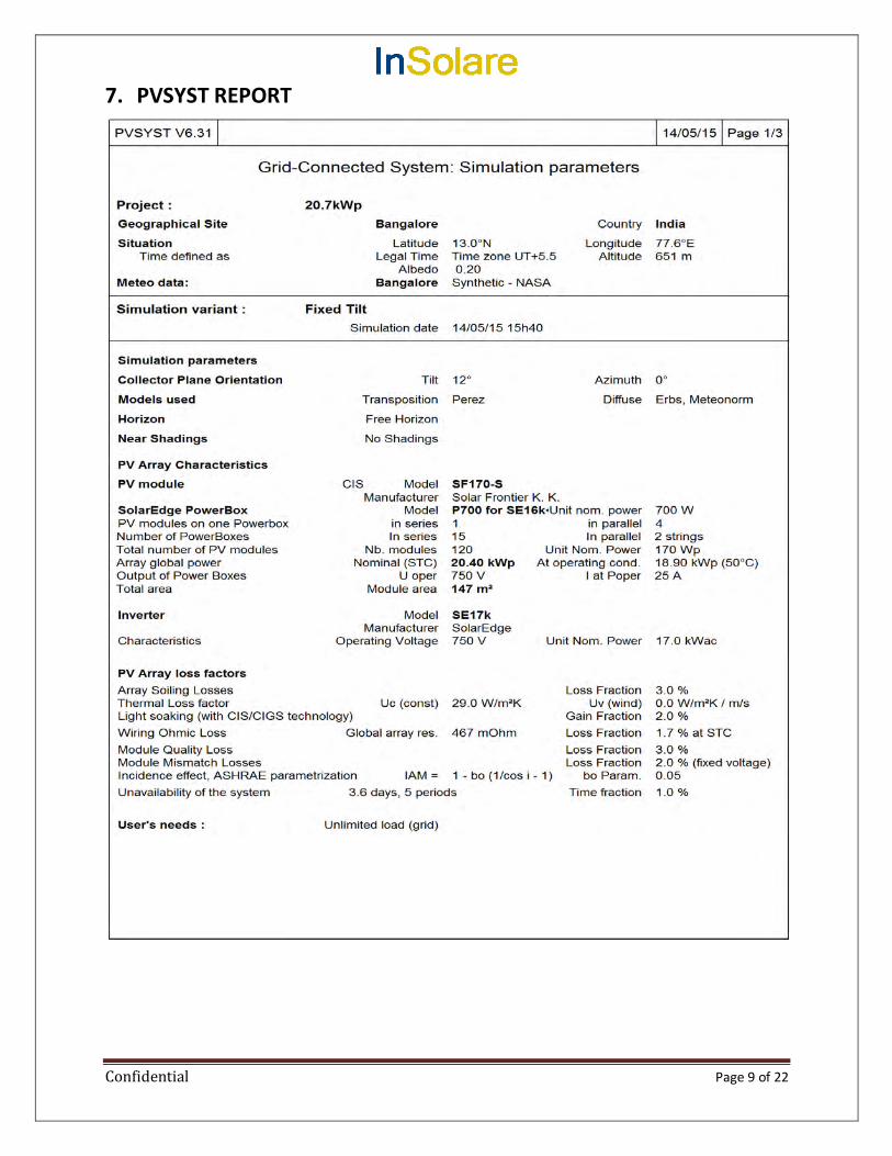
7. PVSYST REPORT

Confidential Page 10 of 22

Confidential Page 11 of 22

Confidential Page 12 of 22
8. ELECTRICAL SLD (Reference Only)

Confidential Page 13 of 22
9. MODULE MOUNTING STRUCTURE
9.1 RCC Flat Roof
The modules will be mounted on the RCC roof on a non-penetrative method. The structure will be supported by placing counter weights against lifting force. Photographs of the envisaged mounting are as below:-
Counter Ballast Weight

Confidential Page 14 of 22
10. COMPONENT MAKE
InSolare offers reputed tier-1 components in Solar system. Following table covers major components and their make.
InSolare Component List and Make
S.no Component name Manufacturer Name Description Remark
1 PV module Reputed make – 170Wp CIS
2 Inverter Solar edge or Equivalent String Inverter
3 Control Cable RR/polycab/SBEE PVC insulation
4 AC cable Polycab/KEI/SBEE 1.1KV level, XPLE aluminum armored
5 DC cable Lapp cable/Leoni/Polycab UV Protected Solar cables
6 LT panel InSolare Design IP*5 enclosure NA
7 DC Connector Nordic/R&X/Pntech/Elmex MC4 connector, UV protected
8 DC SPD JMV/Hakkel/Dehn/Citel Isolator Box, 3 Pole(+, -, E)
9 AC SPD JMV/Hakkel/Dehn/Citel Lt Panel, 4 pole(R,Y,B,E),
10 DC Fuse Mersen/Little fuse 1000Vdc, 15A fuse
11 MCCB Schneider/ABB/Siemens 415V, 4P - Thermal trip based NA
12 ELCB/RCCB Schneider/ABB/Siemens 230V, 2 pole
13 MCB Schneider/ABB/Siemens 415V, 4P - Thermal trip based
14 CT KALPA/Rishab/Elemex/AE Resin Cast Type./ tape wound NA
15 Indication Lamps Siemens/ Technick/schneider LED type
16 Busbar Reputed make Aluminum bus bars NA
17 Terminal Blocks Elemex/Connectwell
18 kWh Meter Schneider/ Secure / L&T
19 Glands & Lugs BRACCO/ Dowells/ Comet GI / PVC
20 Cable Tray Reputed make Hot Dip GI/FRP
21 Junction Box Reputed make FRP
22 Conduits Reputed make PVC/GI
23 Lighting arrester JMV/OBO Conventional
24 Concrete blocks Buildmat/ACC Ltd

Confidential Page 15 of 22
11. TECHNICAL SPECIFICATION OF MAJOR COMPONENTS OF SOLAR PV POWER PLANT
11.1 Solar PV modules and array
1. CIS PV modules type.
2. The mechanical structure to withstand gusts of wind / cyclonic wind up to 120km/hr.
3. The offered modules conform to the latest edition of any of the following IEC/ equivalent BIS
Standards for PV module design qualification and type.
4. PV modules also qualify Salt Mist Corrosion Testing as per IEC61701/IS61701.
5. PV modules used in solar power plants warranted for output wattage, which should not be
less than 90% at the end of 10 years and 80% at the end of 25 years.
11.2 Module mounting structure
The PV modules will be mounted on fixed metallic structures of adequate strength and
appropriate design, which can withstand load of modules and high wind velocities up to 120 km
per hour. The support structure used in the power plants will be hot dip Galvanized Iron (G.I).
11.3 Power Conditioning Unit/Inverter
As SPV array produce direct current electricity, it is necessary to convert this direct current into
alternating current and adjust the voltage levels to match the grid voltage.
Conversion shall be achieved using an electronic Inverter and the associated control and
protection devices. All these components of the system are termed the “Power Conditioning Unit
(PCU)”.
11.4 ACDB (LT Panel)
1. All outdoor devices/equipment to be IP65 as minimum
2. All panels/boards to be provided with LOTO facility
11.5 DC & AC Switches
1. DC SIDE
a. FUSE of suitable rating shall be provided for array input to PCU.
2. AC SIDE
a. MCB/MCCB of suitable rating shall be provided for connection and disconnection of
PCU & load
b. Fault level at each distribution/sub-distribution panel/board to be calculated. CPD
(Circuit protective device) should be MCCB if the fault level is greater than 10kA.
Current limiting enabled MCCBs will not be deemed sufficient to deviate from the
requirement and MCCBs cannot be replaced with MCB where the fault level at any
part of the panel/board is greater than 10kA.
c. MPCB to provide protection to the instrumentation circuits where the fault level is
greater than 10kA.

Confidential Page 16 of 22
11.6 Cables and installation accessories
All the cables shall be supplied as per InSolare preferred Vendor list. The size of the cables
between array interconnections, array to junction boxes, junction box to PCU, PCU to AC
Distribution Box etc shall be so selected to keep the voltage drop and losses to the
minimum. Permissible Wire Drop on DC side shall be <= 2%
All cabling on the roof to be provided with suitable mechanical protection (i.e. cable trays
with top cover or metal conduits). PVC conduits or pipes are not be used.
11.7 Earthing and lightning protection
Earthing:
The array structure of the PV yard shall be grounded properly using adequate number of
earthing kits.
All metal casing or shielding of the power plants shall be thoroughly grounded to ensure
safety of the solar power plants.
Lightning:
The SPV power plants shall be provided with lightning & over voltage protection.
Lightning protection to be as per Indian or relevant IEC standard.
SPD of Type2 to be used on DC side (on each string) if the separation distance from LA is
achieved as per IEC/IS.
SPD of Type1-2 to be used on AC side.

Confidential Page 17 of 22
12. TECHNOLOGY DIFFERENTIATION
InSolare is proud to offer unique Inverter Technology which allows Module level power optimization with monitoring. Our system offers substantial benefit over regular grid tie systems.
12.1 Comparison of InSolare Offered solution vs Others

Confidential Page 18 of 22
13. SOLAR EDGE SYSTEM OVERVIEW

Confidential Page 19 of 22
13.1 POWER OPTIMIZERS
13.2 INVERTER

Confidential Page 20 of 22
14. WHY SOLAR EDGE

Confidential Page 21 of 22

Confidential Page 22 of 22
____________________________________________________________________________________
Regd Office: G35, 1st
Floor, Green Park Market Main, New Delhi-110016, India
Head Office: 5A, ASK Towers, 5th Floor, ITPL Road, AECS Layout, Bangalore 560037, INDIA

SL /TR- STP / NRN HOLDINGS PVT LTD. Date – 16.07.2015
Sobha Limited, Bangalore Page 1 of 9
SOBHA LIMITED, Bangalore
TECHNICAL REPORT
ON
SEWAGE TREATMENT PLANT
50 KLD
Prepared By:
Sobha Limited Sarjapur-Marthahalli Outer Ring Road Devarabisanahalli, Bellandur Post
Bangalore-560103 Tel: + 91-80-49320000

SL /TR- STP / NRN HOLDINGS PVT LTD. Date – 16.07.2015
Sobha Limited, Bangalore Page 2 of 9
TECHNICAL REPORT ON SEWAGE TREATMENT PLANT
NRN Holdings Pvt. Ltd., Bangalore
The treatment philosophy and the parameters for 50 m3 per day Sewage Treatment Plant at NRN Holdings
Pvt. Ltd., is given as follows.
The Sewage Treatment Plant is designed for treating sewage generating from the complex consist of Office
block, training centre and food court at NRN Holdings and to comply with local pollution control board norms.
1. BASIS OF DESIGN & TREATMENT SCHEME
QUANTITY OF SEWAGE
The sewage quantity from domestic sources is considered at a maximum 50 m3/day.
QUALITY OF SEWAGE
The Sewage treatment plant is designed taking the following parameters into account as mentioned below.
Characteristics of wastewater:
S.No Description Unit Influent Treated Effluent
1 Odor - Objectionable Unobjectionable
2 Color Hazen Objectionable <5
3 Turbidity NTU Typical Sewage <2
4 pH - 6.5 – 8.5 6 - 8
5 Oil & Grease mg/l < 10 <10
6 COD mg/l 200 - 600 <50
7 BOD5 mg/l 150 - 450 < / = 10
8 TSS mg/l 70 – 400 <10
9 Turbidity NTU NA < / = 2
10 Total Coliforms No./100ml 107 – 1010 Absent
11 Fecal Coliforms No./100ml 105 – 108 Absent
12 Residual free chlorine Mg/l NA 1 to 3 mg/l

SL /TR- STP / NRN HOLDINGS PVT LTD. Date – 16.07.2015
Sobha Limited, Bangalore Page 3 of 9
PROCESS DESIGN BASIS
Basis of Design
Based on the inputs given by M/s.NRN Holdings the proposed Sewage treatment plant is designed for MBR
technology.
Hydraulic Loading Rate
The total Design hydraulic loading rate for the proposed sewage treatment plant is considered as 50
M3/day. This will be achieved over a period of time as per phase wise development of entire proposed
project at NRN Holdings building.
Hydraulic loading rate calculations are based upon the water demand per Capita per day, assuming 90 % of total
water is converted to sewage
Sewage generation sources are assumed to be from human wastes from Office block, training centre and
food court. Overall estimated sewage generation volume is 50 M3/Day.
PROCESS DESCRIPTION
Treatment Technology
The process description of the sewage treatment facility as follows:
a) The out fall sewer main from the last manhole, (up to 50 m3 per day) will be let into bar screen
chamber thru’ gravity and as well as pumping. Sewage water passes through a stainless steel bar
screen with 20 & 10 mm spacing, where coarse particulate matter is arrested and cleaned
manually.
b) In equalization tank, the sewage is kept in mixed condition in order to avoid septic condition, by
means of coarse bubble grid through twin lobe air blower.
c) The equalized sewage is then pumped to aeration tank through gravity. In Aeration tank where
organic load reduction is achieved by virtue of aerobic microbial activities. Sufficient air shall be
provided with the help of diffused aeration system consisting of tubular EPDM diffusers and twin
lobe air blowers.

SL /TR- STP / NRN HOLDINGS PVT LTD. Date – 16.07.2015
Sobha Limited, Bangalore Page 4 of 9
d) The mixed aerated liquor shall flow through the Membrane Bio Reactor tank. Clear water is
separated out through the membrane filtration. The sludge from the bottom of the tank will be re-
circulated to aeration tank and excess sludge will be transferred to sludge holding tank.
e) After Membrane filtration the treated water is collected in treated water tank and used for
flushing.
f) After treatment in Reverse Osmosis system, STP treated water tank is used cooling tower make
up.
g) Necessary instrumentation is built in to keep process parameters for optimum performance, and to
facilitate smooth operations.
3. DESIGN DETAILS
BAR SCREEN CHAMBER
Bar screen of size 0.75 m X 0.6 m X 0.8 m depth is provided with 20mm and 10 mm screen for screening
the coarse particulate matters
OIL & GREASE TRAP CHAMBER
Oil & grease trap chamber of size 2.1 m X 0.6 m X 1.0 m liquid depth is provided for separation of oil &
grease from the incoming sewage.
EQUALIZATION TANK
Design Flow 50 M3/Day
Retention period 14 Hr
Volume of tank required 29.16 M3
Side Water Depth of Eq. Tank (SWD) 3.0 M
Volume of tank provided 30 M3
No. of tanks provided 1 Nos.
EQUALIZATION TRANSFER PUMP
Purpose: For Pumping from equalization tank to Aeration tank
Flow 50 M3/Day
Pumping hours - 24 hours 24 Hr
Capacity of Pump 2.08 M3/Hr
Add 5% extra capacity
Rev capacity of pumps 2.2 M3/Hr
Approximately 2.5 M3/Hr
Head of Pump = Static Head + Losses 10 M
No of Pumps = 2 Nos. (1W + 1S) (1W+1S) Nos.
Capacity of each pump 2.5 M3/Hr

SL /TR- STP / NRN HOLDINGS PVT LTD. Date – 16.07.2015
Sobha Limited, Bangalore Page 5 of 9
AIR BLOWER FOR EQUALIZATION TANK
Volume of EQT 30
Cu.m/Cu.m.
min
Mixing Air Requirement: 0.01 to 0.015 Cu.m/Cu.m. min 0.015
Cu.m/Cu.m.
min
Blower Capacity 0.45 Cu.m/Min
Blower Capacity in Cu.m /hr 27 Cu.m/Hr
Add 10% extra capacity
Rev capacity of pumps 29.7 M3/Hr
Approximately 30 M3/Hr
Head of Blower = SWD of Equalisation Tank + Losses
(MWC) 3.5 M
No of Blowers = 2 Nos. (1W + 1S) (1W+1S) Nos.
Capacity of each blower 30 M3/Hr
DESIGN OF AERATION TANK
Aeration tank volume = (Q x BOD) / (f/m x MLSS)
= (50 X 350) / (0.1 X 10000)
= 17.5 m3
Actual volume of aeration tank provided = 18 m3
DESIGN OF AIR BLOWER FOR AERATION TANK
Oxygen Demand without de-nitrification (Kg/Day) 1.67 Kg/Day
Air Flow Requirement (m3/Hr) 60.6 m3/Hr
Add 5% extra capacity
Rev capacity of blower 63.6 M3/Hr
Approximately 65 M3/Hr
Head of Blower = SWD of Equalisation Tank + Losses (MWC) 4.5 M
No of Blowers = 3 Nos. (2W + 1S) (1W+1S) Nos.
Capacity of each blower 65 M3/Hr
O2 Required
Sp. Gravity of air x % of Oxygen in Air x α Coefficient x β Coefficient x Oxygen Transfer efficiency of membrane
Where
Sp. Gravity of air 1.2
% Of Oxygen in air
0.232
α Coefficient 0.65
β Coefficient 0.95
Oxygen Transfer Efficiency of Membrane 0.16

SL /TR- STP / NRN HOLDINGS PVT LTD. Date – 16.07.2015
Sobha Limited, Bangalore Page 6 of 9
Sludge re-circulation pump
Design flow = 2.5 m3/hr
4 times of design flow = 10 m3/hr Total No. of pumps provided = 2 Nos. (1W + 1S)
Flow of each pump = 10 m3/hr
MBR permeate pump
Design flow = 4.5 m3/hr
Total No. of pumps provided = 2 Nos. (1W + 1S) Flow of each pump = 4.5 m3/hr
MBR back pulse pump
Design flow = 6.5 m3/hr Total No. of pumps provided = 2 Nos. (1W + 1S)
Flow of each pump = 6.5 m3/hr
MBR
Flow = 50 m3/day
Chlorine Dosing System (HPS Outlet)
Pump Capacity provided = 15 LPH
Dosing tank capacity = 200 litres
Quantity = 1 No.
Sludge Holding Tank
Volume of the tank = 4 m3
Centrifgue feed pump
Pump capacity = 2000 liters/hr
Centrifuge
Centrifuge capacity = 2 m3/hr
Treated Water Tank – I (for flushing)
Volume of the Tank = 15 m3
Treated Water Tank – II (for Landscaping)
Volume of the Tank = 12 m3
Treated Water Tank – II (for HVAC)
Volume of the Tank = 11 m3

SL /TR- STP / NRN HOLDINGS PVT LTD. Date – 16.07.2015
Sobha Limited, Bangalore Page 7 of 9
Equalization
Tank
Sewage Generation from buildings
Aeration Tank MBR Tank
Sludge Digestion
Tank
Centrifuge
Dried Sludge as Fertilizer to Garden
Sludge Recirculation line
Sludge Drain line
Centrifuge feed pump
MBR process
pump
Blower
BSC
Treated Water Tank - 01
Treated Water
Tank 02
O & G
Gardening
Chlorine dosing
System
Ultraviolet
Blower
Reverse Osmosis
system For HVAC
For Flushing Ultraviolet
Blow down to Landscaping
4. PROCESS FLOW CHART

SL /TR- STP / NRN HOLDINGS PVT LTD. Date – 16.07.2015
Sobha Limited, Bangalore Page 8 of 9
5. STP CIVIL SPECIFICATIONS ARE SUMMARIZED AS FOLLOWS
SL.
No. DESCRIPTION QTY MOC Volume
1 Bar Screen Chamber
1
RCC 0.36 Cum
2 Oil & Grease trap chamber 1 RCC 1.26 Cum
3 Equalization Tank 1 RCC 30 Cum
4 Aeration Tank 1 RCC 18 Cum
5 Sludge Holding Tank 1 RCC 4 Cum
6 Treated Water Tank – I (Flushing) 1 RCC 15 Cum
7
Treated Water Tank – II
(Landscaping) 1 RCC 12 Cum
8 Treated Water Tank – III (HVAC) 1 RCC 11 Cum

SL /TR- STP / NRN HOLDINGS PVT LTD. Date – 16.07.2015
Sobha Limited, Bangalore Page 9 of 9
STP MECHANICAL SPECIFICATIONS ARE SUMMARIZED AS FOLLOWS
SL.
No. DESCRIPTION QTY STATUS MOC Size
1 Bar Screen 2
- MSEP 20 & 10 MM
2 Raw sewage transfer pump 2 1W + 1S CI / CI 2.5 m3/hr @ 10
mWC
3 Air blower – EQT 2 1W +1S CI / CI 30 m3/hr @ 0.3
Kg/cm2
4 Air blower for Aeration tank 2 1W + 1S CI / CI 65 M3/HR @ 0.45 Kg/cm2
5 Membrane 1
1W Polyether Sulphonate
-
6 Sludge re-circulation pump 2 1W + 1S CI / CI 10 m3/hr @ 1
Kg/cm2
7 MBR permeate pump 2 1W +1S CI / CI 4.5 m3/hr @ 0.5
Kg/cm2
8 MBR backpulse pump 2 1W +1S CI / CI 6.5 m3/hr @ 0.5
Kg/cm2
9 Chlorine dosing pump –
Treated water pump Outlet 1 1W PP
15 LPH @ 2
Kg/cm2
10 Centrifuge feed pump 2 1W +1S CI / CI 2 m3/hr @ 1
Kg/cm2
11 Centrifuge 1 1W CI / SS -
12 Poly electrolyte dosing pump 1 1W PP 45 LPH @ 2
Kg/cm2

TOTAL WATER REQUIREMENT
78.64 KLD
RECYCLED WATER
REQUIREMENT 39.14 KLD
FRESH WATER
REQUIREMENT 39.50 KLD
HVAC BLOW
DOWN 3 KLD
OFFICE & FOOD
COURT
DOMESTIC USE
39.50 KLD
HVAC 12
KLD
FRESH WATER
REQUIREMENT
FROM AUTHORITY
39.50 KLD
RAIN WATER HARVESTED
(DURING RAINY DAYS)
36 KLD
Water Balance Diagram NRN HOLDINGS PVT LTD @ BANGALORE
SEWAGE TREATMENT
PLANT CAPACITY
50 KLD
OFFICE & FOOD
COURT
FLUSHING
14.48 KLD
LANDSCAPE
APPLICATIO
N 12.66 KLD
TREATED WATER TANK
IN STP
43.59 KLD
START UP
REQUIREMENT
39.14 KLD
TOTAL WATER
REQUIREMENT
78.64 KLD
SURPLUS WATER
AVAILABLE FROM STP
7.45 KLD
36.14 KLD
RO PLANT
20 KLD
8 KLD
1.66 KLD 14.48 KLD
3 KLD


▪SOIL INVESTIGATION ▪SLOPE PROTECTION▪GROUTING▪GROUND ANCHORS▪PILE FOUNDATION▪GROUND IMPROVEMENT ▪ NON‐DESTRUCTIVE TESTING ▪SOIL RESISTIVITY TEST
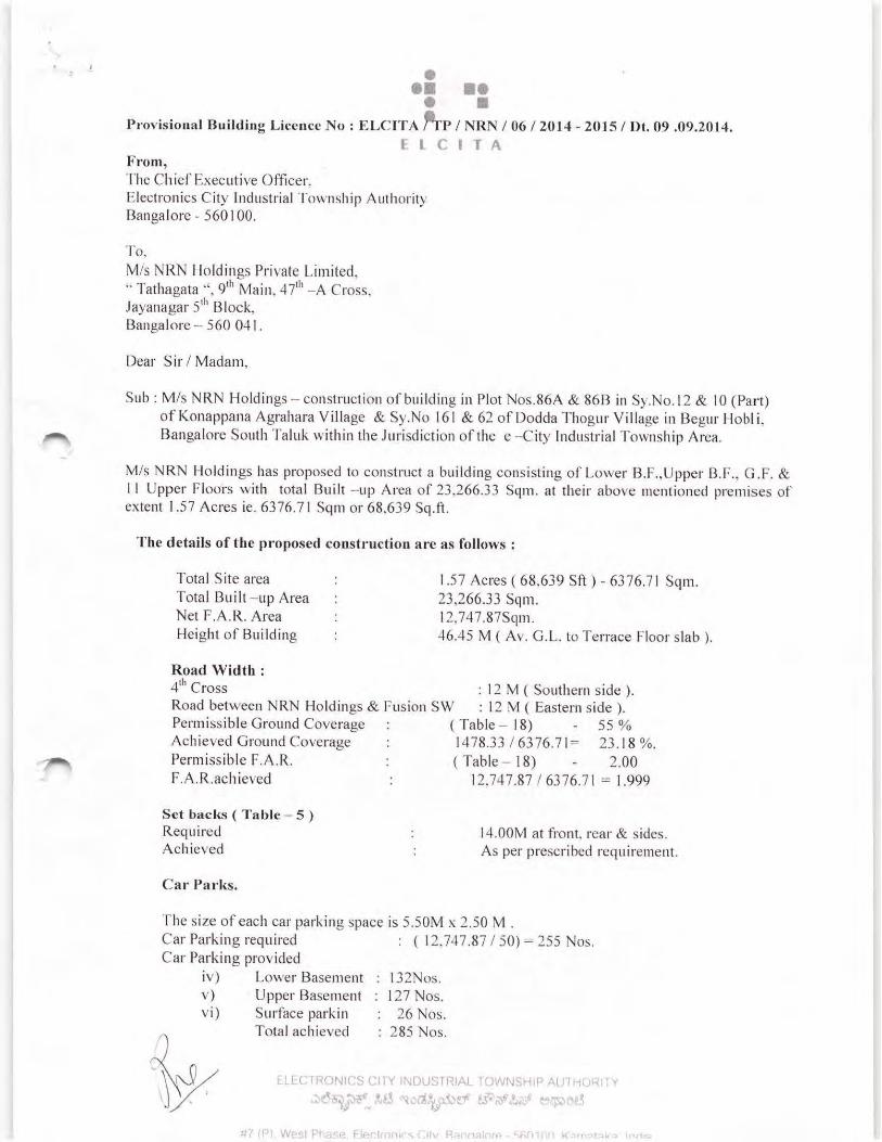
GEOTECHNICAL ENGINEERING REPORT
PROPOSED OFFICE BUILDING AT BEGUR HOBLI,
ELECTRONIC CITY, BANGALORE
CLIENT:
M/s. NRN HOLDINGS PVT. LTD.
BANGALORE
ARCHITECTS:
M/s. RSP ARCHITECTS
BANGALORE
CONSULTANTS:
M/s. TRC ENGINEERING
BANGALORE
August – September 2014
PROJECT NO. GL‐GEO‐14‐093
Geotechnical Investigation By:
GEOLOGICS, #40, Sri Sri Venkatadri, V.Nagenahalli Main
Road, R.T. Nagar Post,Bangalore‐560032
In Association with:
ICON CADSOFT & SURVEYORS INDIA PVT LTD,# 329, 1st Floor,
7th cross, Bangiappa Garden,Lakshmi Road
Shantinagar, Bangalore ‐ 560 027

PROPOSED OFFICE BUILDING ▪BEGUR HOBLI, BANGALORE▪ PROJECT NO. GL‐GEO‐14‐093
Page 2 of 9
8th September 2014 Project No. GL‐GEO‐14‐093 ‐ Draft M/s. NRN Holdings Pvt. Ltd., Bangalore Subject: Geotechnical Investigation Report Project: Proposed Office Building at Begur Hobli, Electronic City, Bangalore
Geologics and Icon Cadsoft & Surveyors India Pvt. Ltd. are pleased to present the attached
geotechnical investigation report for the Proposed Office Building at Begur Hobli, Electronic City,
Bangalore. The purpose of our investigation was to explore and evaluate the subsurface conditions
at various locations on the site in order to develop geotechnical engineering recommendations for
project design and construction.
Recommendations regarding the geotechnical aspects of project design and construction are
presented in the following report. Recommendations provided herein are contingent on the
provisions outlined in the Limitations section of this report. The project
Owner/Designer/Consultant should become familiar with these provisions in order to assess further
involvement by Geologics and other potential impacts to the proposed project.
We appreciate the opportunity of providing our services for this project. If you have questions
regarding this report or if we may be of further assistance, please contact the undersigned.
Sincerely, For GEOLOGICS, Shankar Narayanan.K (M.E. Geotech) Geotechnical Engineer

PROPOSED OFFICE BUILDING ▪BEGUR HOBLI, BANGALORE▪ PROJECT NO. GL‐GEO‐14‐093
Page 3 of 9
Document history and status
Issue No.
Revision No. Date Document/Revision
Type Approved By
1 0 08/09/2014 ENGINEERING REPORT –Draft
KSN
PROPOSED OFFICE BUILDING ▪BEGUR HOBLI, BANGALORE▪ PROJECT NO. GL‐GEO‐14‐093
Page 4 of 9
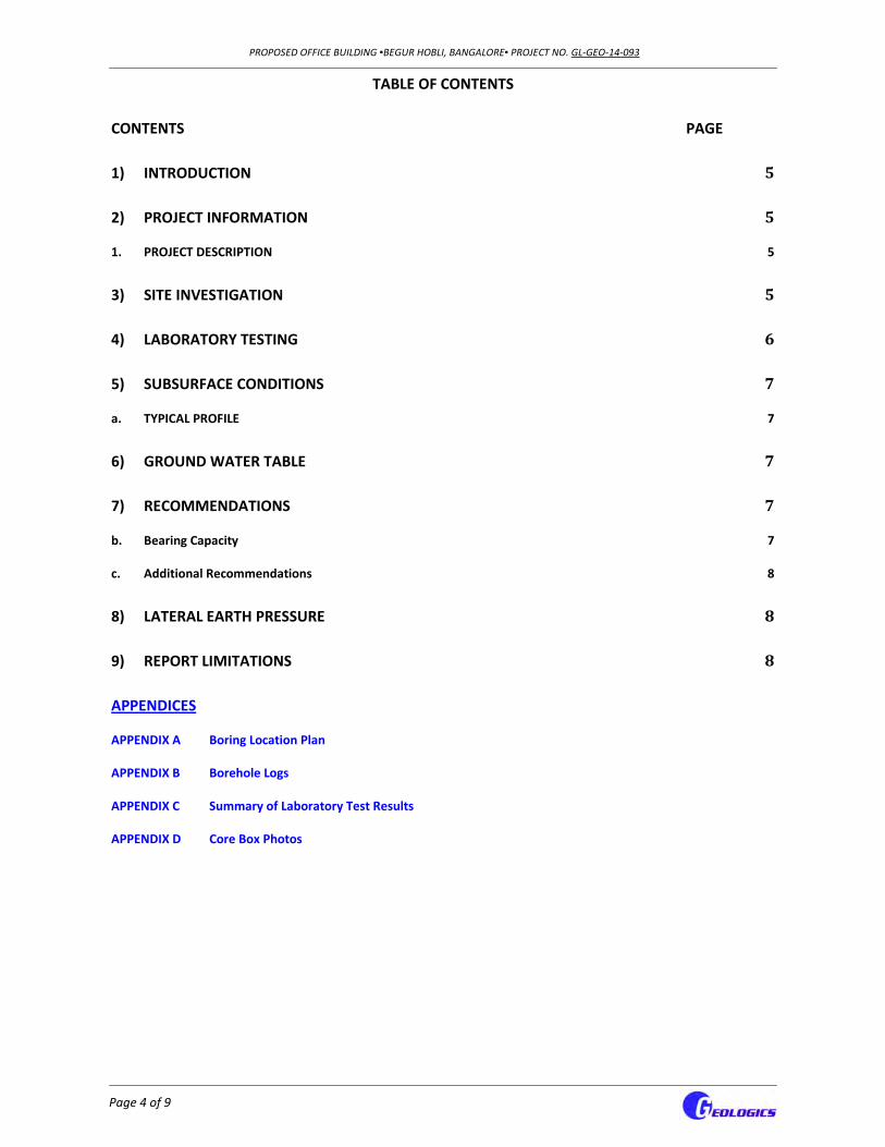
TABLE OF CONTENTS
CONTENTS PAGE
1) INTRODUCTION 5
2) PROJECT INFORMATION 5
1. PROJECT DESCRIPTION 5
3) SITE INVESTIGATION 5
4) LABORATORY TESTING 6
5) SUBSURFACE CONDITIONS 7
a. TYPICAL PROFILE 7
6) GROUND WATER TABLE 7
7) RECOMMENDATIONS 7
b. Bearing Capacity 7
c. Additional Recommendations 8
8) LATERAL EARTH PRESSURE 8
9) REPORT LIMITATIONS 8
APPENDICES
APPENDIX A Boring Location Plan
APPENDIX B Borehole Logs
APPENDIX C Summary of Laboratory Test Results
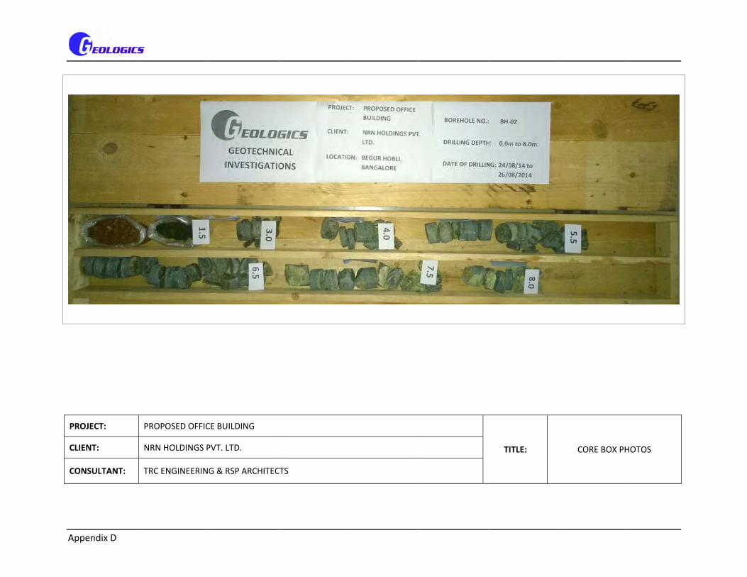
APPENDIX D Core Box Photos

PROPOSED OFFICE BUILDING ▪BEGUR HOBLI, BANGALORE▪ PROJECT NO. GL‐GEO‐14‐093
Page 5 of 9
1) INTRODUCTION
The Geotechnical Engineering Report has been completed for the Proposed Office Building at
Begur Hobli, Electronic City, Bangalore. A total of 05 boreholes designated BH‐01 thorough BH‐
05 was drilled to depths of 8.0m/13.0m below existing ground surface.
The purpose of this Geotechnical Investigation work is to provide information and geotechnical
engineering recommendation as described below:
To determine the nature, depth and
extent of the different soils underlying
the site
To determine the engineering
properties of the soils
To determine if the soil materials are
suitable for construction purposes
To assess founding conditions for the
construction of the facility
To comment on shallow groundwater
or seepage, if any, and
To identify any other geotechnical
aspects that may be relevant to the
construction of the facility.
This draft report provides the details of field and laboratory tests conducted and
recommendations for type and depth of foundation.
Boring location plan is presented in Appendix – A, the borehole logs are presented in Appendix –
B and the Summary Laboratory Test Results are presented in Appendix – C.
2) PROJECT INFORMATION
1. PROJECT DESCRIPTION
Site Layout Refer Appendix – A, Boring Location Plan
Site Location Begur Hobli, Near Electronic City, Bangalore
Structure Details G+11 Floors + Terrace, 2 Basement, Commercial Building
Existing Structures NIL
Current Ground Cover/Site Condition
Covered with sandy SILT/CLAY
Existing Topography Flat
3) SITE INVESTIGATION
The field work for the geotechnical investigation works were carried out from 21st August 2014
to 28th August 2014. Altogether 05 boreholes were drilled to investigate the subsurface in the
area of the planned development. The locations of all the drilled boreholes were identified and
marked on the site by Geologics as per the drawing provided. Drilling was performed using

PROPOSED OFFICE BUILDING ▪BEGUR HOBLI, BANGALORE▪ PROJECT NO. GL‐GEO‐14‐093
Page 6 of 9
rotary method with mud circulation. Field test data and observations of all boreholes are
presented in Appendix B.
During drilling of boreholes, Standard Penetration Tests; SPT were conducted in accordance with
IS 2131 – 1981. The test uses a thick‐walled sample tube, with an outside diameter of 50 mm
and an inside diameter of 35 mm, and a length of around 650 mm. This is driven into the ground
at the bottom of a borehole by blows from a slide hammer with a weight of 63.5 kg falling
through a distance of 760 mm. The sample tube is driven 150 mm into the ground and then the
number of blows needed for the tube to penetrate each 150 mm up to a depth of 450 mm is
recorded. The sum of the number of blows required for the second and third 150mm of
penetration is termed the "standard penetration resistance" or the "N‐value". In cases where 50
blows are insufficient to advance it through a 150 mm (In a very dense and/or cemented soil
layers), the penetration after 50 blows is recorded. The blow count provides an indication of the
density of the ground, and it is used in many empirical geotechnical engineering formulae.
SPT was performed wherever the soil conditions are appropriate for SPT and the N‐values are
reported. Disturbed SPT and bulk samples collected during drilling were retained in sealed,
labeled plastic bags. Relatively undisturbed soil samples, if available, were taken from cohesive
soils using Shelby tube samplers, later transported to our laboratory for further sample
descriptions and determination of engineering properties.
4) LABORATORY TESTING
After classification and carrying out the geological description on the obtained samples, a
laboratory tests program was issued; this program contained the required tests on selected
samples in order to determine the physical and mechanical properties of the ground materials.
The performed tests were performed according to the relevant parts of Indian Standards as
follows.
Water content IS 2720 : Part 2 : 1973 Grain Size Analysis IS 2720 : Part 4 : 1985 Liquid and Plastic Limit IS 2720 : Part 5 : 1985 Point Load Index Strength of rock samples IS 8764: 1998, Reaffirmed 2008 Chemical Analysis of soil Samples
The summary of Laboratory tests of the borehole samples are presented in Appendix C.
*Note: The chemical analysis results will be furnished in the final report as the analysis is still in progress.

PROPOSED OFFICE BUILDING ▪BEGUR HOBLI, BANGALORE▪ PROJECT NO. GL‐GEO‐14‐093
Page 7 of 9
5) SUBSURFACE CONDITIONS
a. TYPICAL PROFILE
The boreholes drilled shows that there are general similarities and continuities of the subsurface
materials with local variations. In boreholes BH‐01 to BH‐04, sandy SILT/CLAY or silty/clayey
SAND was observed from GL to an average depth of 2.5m followed by whitish grey SOFT ROCK
down to an average depth of 3.8m after which whitish grey HARD ROCK was encountered till the
termination depth of the boreholes. BH‐05 revealed presence of sandy SILT/CLAY from GL down
to an average depth of 4.0m followed by silty/clayey SAND till 8.0m after which brownish black
silty SAND (highly disintegrated rock) was observed till 11.8m. This layer was followed by Whitish
grey soft rock till the termination depth of the borehole. BH‐01, BH‐02 and BH‐03 were
terminated at 8.0m bgl, BH‐04 was terminated at 9.0m bgl and BH‐05 was terminated at 13.0m
bgl.
6) GROUND WATER TABLE
The boreholes were observed while drilling and immediately after completion for presence of
groundwater/seepage water. Water table/seepage water was not observed in any of the
boreholes during the time of investigation within the exploration depth. However, during some
periods of the year there may be variation in the levels of groundwater/seepage water.
Fluctuations in ground water levels/seepage water are affected by the variations in the amount
of rainfall, runoff, evaporation and other hydrological factors not apparent at the time of drilling.
Longer monitoring would be required to evaluate long term groundwater conditions.
7) RECOMMENDATIONS
Based on the conditions encountered in borings and engineering analysis, the proposed
structure can be supported on footings bearing on the native soil at the site provided that the
following recommendations are followed. Recommendations regarding design and construction
of foundations are given below.
b. Bearing Capacity
For the proposed double basement structure (depth of basement considered as 7.0m bgl) the
foundation can be placed at a depth of 8.0m bgl. A competent engineer will be required during
footing construction to verify the bearing stratum. The foundation depth and the net allowable
SBC for the proposed structure is given below.
PROPOSED OFFICE BUILDING ▪BEGUR HOBLI, BANGALORE▪ PROJECT NO. GL‐GEO‐14‐093
Page 8 of 9
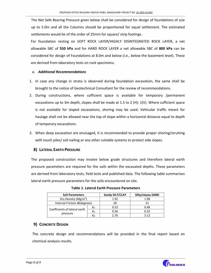
The Net Safe Bearing Pressure given below shall be considered for design of foundations of size
up to 5.0m and all the Columns should be proportioned for equal settlement. The estimated
settlements would be of the order of 25mm for square/ strip footings.
For foundation resting on SOFT ROCK LAYER/HIGHLY DISINTEGRATED ROCK LAYER, a net
allowable SBC of 550 kPa and for HARD ROCK LAYER a net allowable SBC of 800 kPa can be
considered for design of Foundations at 8.0m and below (i.e., below the basement level). These
are derived from laboratory tests on rock specimens.
c. Additional Recommendations
1. In case any change in strata is observed during foundation excavation, the same shall be
brought to the notice of Geotechnical Consultant for the review of recommendations.
2. During constructions, where sufficient space is available for temporary /permanent
excavations up to 3m depth, slopes shall be made at 1.5 to 2 (H): 1(V). Where sufficient space
is not available for sloped excavations, shoring may be used. Vehicular traffic meant for
haulage shall not be allowed near the top of slope within a horizontal distance equal to depth
of temporary excavations.
3. When deep excavation are envisaged, it is recommended to provide proper shoring/strutting
with touch piles/ soil nailing or any other suitable systems to protect side slopes.
8) LATERAL EARTH PRESSURE
The proposed construction may involve below grade structures and therefore lateral earth
pressure parameters are required for the soils within the excavated depths. These parameters
are derived from laboratory tests, field tests and published data. The following table summarizes
lateral earth pressure parameters for the soils encountered on site.
Table 1. Lateral Earth Pressure Parameters
Soil Parameters Sandy SILT/CLAY Silty/clayey SAND
Dry Density (Mg/m3) 1.92 1.98
Internal Friction Φ(degrees) 28 31
Coefficients of lateral earth pressure
Ko 0.53 0.48
Ka 0.36 0.32
Kp 2.76 3.12
9) CONCRETE DESIGN
The concrete design and recommendations will be provided in the final report based on
chemical analysis results.

PROPOSED OFFICE BUILDING ▪BEGUR HOBLI, BANGALORE▪ PROJECT NO. GL‐GEO‐14‐093
Page 9 of 9
10) REPORT LIMITATIONS
This report is based on local experience and the findings at the exploratory locations. If different
subsoil conditions are encountered, the same may be brought to our notice and
recommendations submitted herein will be reviewed and revised as required. This report has
been prepared for the exclusive use of the client and their approved agents for specified
application to this project. It has been prepared in accordance with generally accepted soil and
foundation engineering practices.
APPENDIX – A
Borehole Location Plan

E+
49
70
E+
50
00
E+
50
40
E+
50
80
E+
50
80
E+
49
70
E+
50
40
E+
50
00
N+2970
N+3000
N+3040
N+3080
N+3120 N+3120
N+2970
N+3080
N+3040
N+3000
61.914m (203'2")
96.6
87m
(31
7'3"
)62.651m (205'7")
110.
277m
(36
1'10
")
1
9
SCALE
99.43
To Electronic City 1st Gate
To Hosur Road

APPENDIX – B
Borehole Logs

BH-01
U+T,fs
0.90
Greyish brownsandy SILT/CLAY
fS+U,t
2.90
Yellowish/greyish brown silty/clayey, SAND
Z
4.50
Whitish Grey, moderately to highly fracturedModerately weak, SOFT ROCK, obtained inhighly fractured form TCR-23%, SCR-18%, RQD-0%
Z
6.00
Whitish Grey, moderately to highly fractured, moderately weak, HARD ROCK, obtained inhighly fractured form, TCR-50%, SCR-22%, RQD-0%
Z
7.00
Whitish Grey, moderately to highly fractured,moderately weak, HARD ROCK, obtained in highly fractured form TCR-69%, SCR-62%, RQD-0%
Z
8.00
Whitish Grey, moderately to highly fractured,moderately weak,HARD ROCK, obtained in highly fractured form, TCR-82%, SCR-80%, RQD-0%
4.50
6.00
7.00
8.00
DS 0.50
SPT - 5/8/13=21 1.50
SPT - 29-6cm = >100 3.00
1.00
2.00
3.00
4.00
5.00
6.00
7.00
8.00
U, Silt
T, Clay
fS, Fine sand
Z, Rock
Core sample
Special sample
DRILLING METHOD: ROTARY DRILLING WITH MUD CIRCULATIONDATE: 22/08/2014 to 23/08/2014 BOREHOLE DIA: 150mm
BOREHOLE TERMINATED AT 8.0m bgl MAXIMUM DEPTH OF EXPLORATION - NO WATER TABLE
M/s. GEOLOGICS, # 41, SRI SRI VENKATADRIV.NAGENAHALLI MAIN ROAD, RT NAGAR POST, BANGALORE
Scale 1:50 Title: PROPOSED OFFICE BUILDING
Date: 08/09/2014File: BH-1
Page No.: Project: GL-GEO-14/093

A
BH-02
A+T,u,fs
0.50
Yellowish redsandy SILT/CLAYFilled up soil
fS+U,t
1.80
Greyish brownsilty/clayey, SAND with gravelVery dense
Z
3.00
Whitish Grey, moderately to highly fracturedModerately weak, SOFT ROCK, obtained inhighly fractured form TCR-<10%, SCR-<10%, RQD-0%
Z
4.50
Whitish Grey, moderately to highly fracturedModerately weak, SOFT ROCK, obtained inhighly fractured form TCR-18%, SCR-<10%, RQD-0%
Z
5.50
Whitish Grey, moderately to highly fractured, moderately weak, HARD ROCK, obtained inhighly fractured form, TCR-33%, SCR-12%, RQD-0%
Z
6.50
Whitish Grey, moderately to highly fractured,moderately weak, HARD ROCK, obtained in highly fractured form TCR-47%, SCR-22%, RQD-0%
Z
7.50
Whitish Grey, moderately to highly fractured,moderately weak,HARD ROCK, obtained in highly fractured form, TCR-46%, SCR-9%, RQD-0%
Z
8.00
Whitish Grey, moderately to highly fractured,moderately weak,HARD ROCK, obtained in highly fractured form, TCR-20%, SCR-0%, RQD-0%
3.00
4.50
5.50
6.50
7.50
8.00
DS 0.50
SPT - 30-5cm=>100 1.50
1.00
2.00
3.00
4.00
5.00
6.00
7.00
8.00
A A, Filling
T, Clay
U, Silt
fS, Fine sand
Z, Rock
Core sample
Special sample
DRILLING METHOD: ROTARY DRILLING WITH MUD CIRCULATIONDATE: 24/08/2014 to 26/08/2014 BOREHOLE DIA: 150mm
BOREHOLE TERMINATED AT 8.0m bgl MAXIMUM DEPTH OF EXPLORATION - NO WATER TABLE
M/s. GEOLOGICS, # 41, SRI SRI VENKATADRIV.NAGENAHALLI MAIN ROAD, RT NAGAR POST, BANGALORE
Scale 1:50 Title: PROPOSED OFFICE BUILDING
Date: 08/09/2014File: BH-2
Page No.: Project: GL-GEO-14/093

A
BH-03
A+T,u,fs
0.50
Yellowish brownsandy SILT/CLAYFilled up soil
fS+U,t
2.00
Yellowish brownsilty/clayey, SANDVery dense
fS+U,t
3.00
Yellowish brownsilty, SAND (fragments of soft rock)Running sample
Z
3.80
Whitish Grey, moderately to highly fracturedModerately weak, SOFT ROCK, obtained inhighly fractured form TCR-33%, SCR-0%, RQD-0%
Z
5.00
Whitish Grey, moderately to highly fracturedModerately weak, SOFT ROCK, obtained inhighly fractured form TCR-32%, SCR-14%, RQD-0%
Z
6.00
Whitish Grey, moderately to highly fractured, moderately weak, HARD ROCK, obtained inhighly fractured form, TCR-36%, SCR-5%, RQD-0%
Z
7.00
Whitish Grey, moderately to highly fractured,moderately weak, HARD ROCK, obtained in highly fractured form TCR-44%, SCR-32%, RQD-0%
Z
8.00
Whitish Grey, moderately to highly fractured,moderately weak,HARD ROCK, obtained in highly fractured form, TCR-36%, SCR-7%, RQD-0%
4.00
5.00
6.00
7.00
8.00
DS 0.50
SPT - 32-5cm=>100 1.50
1.00
2.00
3.00
4.00
5.00
6.00
7.00
8.00
A A, Filling
T, Clay
U, Silt
fS, Fine sand
Z, Rock
Core sample
Special sample
DRILLING METHOD: ROTARY DRILLING WITH MUD CIRCULATIONDATE: 26/08/2014 to 27/08/2014 BOREHOLE DIA: 150mm
BOREHOLE TERMINATED AT 8.0m bgl MAXIMUM DEPTH OF EXPLORATION - NO WATER TABLE
M/s. GEOLOGICS, # 41, SRI SRI VENKATADRIV.NAGENAHALLI MAIN ROAD, RT NAGAR POST, BANGALORE
Scale 1:50 Title: PROPOSED OFFICE BUILDING
Date: 08/09/2014File: BH-3
Page No.: Project: GL-GEO-14/093

BH-04
U+T,fs
0.75
Brownish redsandy SILT/CLAY
fS+U,t
2.00
Brownish/yellowish redsilty/clayey, SANDVery dense
fS+U,t
3.00
Brownish blacksilty, SAND (fragments of soft rock)Running sample
Z
4.00
Whitish Grey, moderately to highly fracturedModerately weak, SOFT ROCK, obtained inhighly fractured form TCR-26%, SCR-10%, RQD-0%
Z
5.00
Whitish Grey, moderately to highly fracturedModerately weak, SOFT ROCK, obtained inhighly fractured form TCR-<10%, SCR-<10%, RQD-0%
Z
6.00
Whitish Grey, moderately to highly fractured, moderately weak, HARD ROCK, obtained inhighly fractured form, TCR-18%, SCR-6%, RQD-0%
Z
7.00
Whitish Grey, moderately to highly fractured,moderately weak, HARD ROCK, obtained in highly fractured form TCR-26%, SCR-9%, RQD-0%
Z
8.00
Whitish Grey, moderately to highly fractured,moderately weak,HARD ROCK, obtained in highly fractured form, TCR-21%, SCR-6%, RQD-0%
Z
9.00
Whitish Grey, moderately to highly fractured,moderately weak,HARD ROCK, obtained in highly fractured form, TCR-37%, SCR-7%, RQD-0%
4.00
5.00
6.00
7.00
8.00
9.00
DS 0.50
SPT - 7/19/45=>50 1.50
1.00
2.00
3.00
4.00
5.00
6.00
7.00
8.00
9.00
U, Silt
T, Clay
fS, Fine sand
Z, Rock
Core sample
Special sample
DRILLING METHOD: ROTARY DRILLING WITH MUD CIRCULATIONDATE: 21/08/2014 to 22/08/2014 BOREHOLE DIA: 150mm
BOREHOLE TERMINATED AT 9.0m bgl MAXIMUM DEPTH OF EXPLORATION - NO WATER TABLE
M/s. GEOLOGICS, # 41, SRI SRI VENKATADRIV.NAGENAHALLI MAIN ROAD, RT NAGAR POST, BANGALORE
Scale 1:50 Title: PROPOSED OFFICE BUILDING
Date: 08/09/2014File: BH-4
Page No.: Project: GL-GEO-14/093

A
BH-05
A+T,fs
0.75
Brownish redsandy SILT/CLAYFilled up soil
U+T,fs
3.80
Yellowish/brownish redsandy SILT/CLAYStiff to very stiff
fS+U,t
6.60
Whitish/yellowish brown silty/clayey SANDDense
fS+U,t
8.00
Yellowish brownsilty/clayey SAND with gravelDense to very dense
fS+Zv,t
11.80
Blackish brownsilty SAND (highly disintegrated rock)Dense to very dense
Z
13.00
Whitish Grey, moderately to highly fracturedModerately weak, SOFT ROCK, obtained inhighly fractured form TCR-22%, SCR-5%, RQD-0%
DS 0.50
SPT - 5/6/8=14 1.50
SPT-7/11/12=23 3.00
SPT-6/13/17=30 4.50
SPT-11/14/19=33 6.00
SPT-29-5cm=>100 7.50
1.00
2.00
3.00
4.00
5.00
6.00
7.00
8.00
9.00
10.00
11.00
12.00
13.00
A A, Filling
T, Clay
fS, Fine sand
U, Silt
Zv, Rock, weathered
Z, Rock
Special sample
DRILLING METHOD: ROTARY DRILLING WITH MUD CIRCULATIONDATE: 27/08/2014 to 28/08/2014 BOREHOLE DIA: 150mm
BOREHOLE TERMINATED AT 13.0m bgl MAXIMUM DEPTH OF EXPLORATION - NO WATER TABLE
M/s. GEOLOGICS, # 41, SRI SRI VENKATADRIV.NAGENAHALLI MAIN ROAD, RT NAGAR POST, BANGALORE
Scale 1:65 Title: PROPOSED OFFICE BUILDING
Date: 08/09/2014File: BH-5
Page No.: Project: GL-GEO-14/093

APPENDIX – C
Summary of Laboratory Test Results

Boulders %
Cobbles %
Gravel %
Sand %
Silt %
Clay %
Liquid Lim
it %
Plastic Lim
it %
PI
Point Load
Index
Mpa
UCS Mpa
1.5m 23.5 0.0 0.0 4.9 54.4 52 30 31 ‐ ‐
8.3 ‐ ‐ ‐ ‐ ‐ ‐ ‐ ‐ 0.22 4.8
1.5m 9.5 0.0 0.0 11.6 45.3 ‐ ‐ ‐ ‐ ‐
6.0m ‐ ‐ ‐ ‐ ‐ ‐ ‐ ‐ 0.11 2.4
4.0m ‐ ‐ ‐ ‐ ‐ ‐ ‐ ‐ 0.07 1.6
6.5m ‐ ‐ ‐ ‐ ‐ ‐ ‐ ‐ 0.07 1.6
1.5m 19.1 0.0 0.0 24.2 21.5 ‐ ‐ ‐ ‐ ‐
7.0m ‐ ‐ ‐ ‐ ‐ ‐ ‐ ‐ 0.11 2.4
1.5m 18.2 ‐ ‐ ‐ ‐ ‐ ‐ ‐ ‐ ‐
4.5m 13.7 ‐ ‐ ‐ ‐ ‐ ‐ ‐ ‐ ‐
13.0m ‐ ‐ ‐ ‐ ‐ ‐ ‐ ‐ 0.04 0.8‐
BH‐03
2 BH‐02
3
Summary of Lab Test Results Boreholes
Sl. No BH no. Depth ( m )
Natural
Moisture
Content (%)
Particle Size Analysis Atterberg Limits
4 BH‐04
5 BH‐05
40.7
43.1
54.3
‐
‐
‐
‐
‐
‐
‐
1 BH‐01

APPENDIX – D
Core Box Photos

A
C
C
Appendix D
PROJECT:
CLIENT:
CONSULTANT:
PROPOSED OFFIC
NRN HOLDINGS P
TRC ENGINEERING
CE BUILDING
PVT. LTD.
G & RSP ARCHITECCTS
TITLE: CORE BOX PH
HOTOS
A
C
C
Appendix D
PROJECT:
CLIENT:
CONSULTANT:
PROPOSED OFFIC
NRN HOLDINGS P
TRC ENGINEERING
CE BUILDING
PVT. LTD.
G & RSP ARCHITECCTS
TITLE: CORE BOX PH
HOTOS

A
C
C
Appendix D
PROJECT:
CLIENT:
CONSULTANT:
PROPOSED OFFIC
NRN HOLDINGS P
TRC ENGINEERING
CE BUILDING
PVT. LTD.
G & RSP ARCHITECCTS
TITLE: CORE BOX PH
HOTOS

A
C
C
Appendix D
PROJECT:
CLIENT:
CONSULTANT:
PROPOSED OFFIC
NRN HOLDINGS P
TRC ENGINEERING
CE BUILDING
PVT. LTD.
G & RSP ARCHITECCTS
TITLE: CORE BOX PH
HOTOS

A
C
C
Appendix D
PROJECT:
CLIENT:
CONSULTANT:
PROPOSED OFFIC
NRN HOLDINGS P
TRC ENGINEERING
CE BUILDING
PVT. LTD.
G & RSP ARCHITECCTS
TITLE: CORE BOX PH
HOTOS

TOTAL WATER REQUIREMENT
78.64 KLD
RECYCLED WATER
REQUIREMENT 39.14 KLD
FRESH WATER
REQUIREMENT 39.50 KLD
HVAC BLOW
DOWN 3 KLD
(1500 mg/l)
OFFICE & FOOD
COURT DOMESTIC
USE 39.50 KLD
(200 mg/l)
HVAC 12
KLD
(100 mg/l)
FRESH WATER
REQUIREMENT
FROM AUTHORITY
39.50 KLD
(200 mg/l)
RAIN WATER HARVESTED
(DURING RAINY DAYS)
36 KLD
Mass Balance Diagram NRN HOLDINGS PVT LTD @ BANGALORE
SEWAGE TREATMENT
PLANT CAPACITY
50 KLD
OFFICE & FOOD
COURT FLUSHING
14.48 KLD
(400 mg/l)
LANDSCAPE
APPLICATION
12.66 KLD
(945 mg/l)
TREATED WATER TANK
IN STP
43.59 KLD
(400 mg/l)
START UP
REQUIREMENT
39.14 KLD
TOTAL WATER
REQUIREMENT
78.64 KLD
SURPLUS WATER
AVAILABLE FROM STP
7.45 KLD
(400 mg/l)
36.14 KLD
(400 mg/l)
20 KLD
(400 mg/l)
8 KLD
(850 mg/l)
1.66 KLD
(400 mg/l)
14.48 KLD
(400 mg/l)
RO PLANT
3 KLD
(1500 mg/l)