Embed Size (px)
Citation preview

AD-A261 699
AD
TECHNICAL REPORT ARCCB-TR-92049
APPLICATIONS OF ADVANCEDMATERIALS TO CANNON PRODUCTION
EDWARD TROIANO
DTICS ARO 3 1993;
DECEMBER 1992
US ARMY ARMAMENT RESEARCH,DEVELOPMENT AND ENGINEERING CENTER
CLOSE COMBAT ARMAMENTS CENTERBENtT LABORATORIES
WATERVLIET, N.Y. 12189-4060
APPROVED FOR PUBLIC RELEASE; DISTRIBUTION UNLIMITED
93-04406 2 074

DISCLAIMER
The findings in this report are not to be construed as an official
Department of the Army position Unless so designated by other authorized
documents.
The use of trade name(s) and/or manufactuTer(s) does not constitute
an official indorsement or approval.
DESTRUCTION NOTICE
For classified documents, follow the procedures in DoD 5200.22-M,
Industrial Security Manual, Section 11-19 or DoD 5200.1-R, Information
Security Program Regulation, Chapter IX.
For unclassified, limited documents, destroy by any method that will
prevent disclosure of contents or reconstruction of the document.
For unclassified, unlimited documents, destroy when the report is
no longer needed. Do not return it to the originator.

IFarm ApprovedREPORT DOCUMENTATION PAGE 0MB No. 0704-0188
Punbk reporting burdenfl or this collection of information is estimated to average I hour per response. including the time for reviewing instructions. searchiing existing data sources.gaheig n maintaining the data needed, and completing and reviewing the collection of information. Send comments regarding this burden estimate or any other aspect Of thiscolcinof information Including suggestions for reducing this burden. to Washington Headq1iuartersl Services. Directorate for Information Operations and Reports. 1215 Jefferson
Oavis Highway. Suite 1204. Arlington. VdA 22202-4302. and to the Office of Management and Budgert. Paperworkc Reduction Project (0704.0188). Washington. OC 20503.
1. AGENCY USE ONLY (Leave blank) 12.JPO ýD 3.J-BEKRT TYPE AND DATES COVERED
4. TITLE AND SUBTITLE 5. FUNDING NUMBERSAPPLUCAT1ONS OF ADVANCED MATERIALS AMCMS No. 72801 1E620035TO CANNON PRODUCTION 1' PRON No. M76F2023M71A
6. AUTHOR(S)
Edward Trojano
7. PERFORMING ORGANIZATION NAME(S) AND ADORESS(ES) 8. PERFORMING ORGANIZATIONU.S. Army ARDEC ARCCB-TR-92049Benet, Lbabratories SMCAR-CCB-TLWatervijet. NY 12189-4050
9. SPONSORING/ MONITORING AGENCY NAME(S) AND ADORESS(ES) 10. SPONSORING iMONITORINGAGENCY REPORT NUMBER
U.S. Army ARDECClose Combat Armaments CenterPicatimy ArsenaL NJ 07806-5000
11. SUPPLEMENTARY NOTES
12a. DISTRIBUTION /AVAILABIUITY STATEMENT t2b. DISTRIBUTION CODE
Approved for public release; distribution unlimited.
13. ABSTRACT (Maximumn 200 words)
This report summarizes various techniques that were investigated as possible manufacturing methods to produce advanced alloy gun tubes.Three mataials, ftaizuim alloy (Ti 38644). inunbae alloy (AF 1410), and alwumium, ratrix-silicori carbide fiber Metal matrix composites(Al-SiC MMC). were studied for possible application to cannon productiont techniques. Techniques of manufacture included induictioni coilshrink* fitting, cold rotary forgig. and onamifacture in place Material Prop811eY investigations were unkderam in order to determine keycritcal parmeters necessay to design gum tubas with dhe previously mentioned materials.
14. SUBJECT TERMS 15. NUMBER OF~gAGES
TI138644. AP 1410. Al-SiC MMCII Induction Coil. Shrink Fining.,Cold Rowy Forging., Stiffariera. Lmas Welding., Typing Mowmem 16. PRICE CODE
17. SECURIT CLASSIFICATION 1B. SECURITY CLASSIFICATION 19. SECURITY CLASSIFICATION 20. LIMITATION OF ABSTRACTOF REPOXT OF THIS PAGE OF ABSTRACT
UNCLASSDUD I~ AW UNLSU I ULNSN 75A00O1.2W0SS00 Standard Forrm 298 (Rtv. 2-89)
Preecr*01d bV ANSI Stil. Z39-18290-102

TABLE OF CONTENTSPage
PROJECT BACKGROUND/OBJECTIVE ................................................. I
MATERIALS INVESTIGATED ....................................................... 1
PROBLEM AREAS ................................................................ 1
APPROACH ..................................................................... 2
Method of Manufacturing with Ti 38644 ........................................... 2
Method of Manufacturing with Al-SiC MMC ........................................ 3
Property Measurement of Ti 38644 ............................................... 4
Property Measurement of AF 1410 ............................................... 4
CONCLUSIONS .................................................................. 4
REFERENCES ................................................................... 5
APPENDIX A ................................................................... 24
TABLES
1. Results of High Temperature Tensile Testing of Ti 38644 ............................... 7
2. Comparison of Pre- and Post-Forging Mechanical Properties of Ti 38644 ..................... 8
3. Results of High Temperature Tensile Testing of AF 1410 ............................... 9
LIST OF ILLUSTRATIONS
1. Laser 105 proof-of-principle gun tube with stiffeners .................................. 10
2. Induction coil shrink fit tower .................................................. 11
3. Prototype test fixture used to cold rotary forge Ti 38644 ............................... 12
4. Forging Ti 38644 with water quench bath being applied ................................ 13
5. Ultimate tensile strength versus temperature for Ti 38644 ............................... 14
6. 0.1 percent yield strength versus temperature for Ti 38644 .............................. 15
7. Percent reduction in area versus temperature for Ti 38644 .............................. 16
8. Ultimate tensile strength of pre- and post-forged conditions for Ti 38644 .................... 17
i

9. 0.1 percent yield strength of pre, and post-forged conditions for Ti 38644 ................... 18
10. Percent reduction in area of pre- and post-forged conditions for Ti 38644 ................... 19
11. Charpy v-notch of pre- and post-forged conditions for Ti 38644 .......................... 20
12. Ultimate tensile strength versus temperature for AF 1410 ............................... 21
13. 0.1 percent yield strength versus temperature for AF 1410 .............................. 22
14. Percent reduction in area versus temperature for AF 1410 .............................. 23
ii
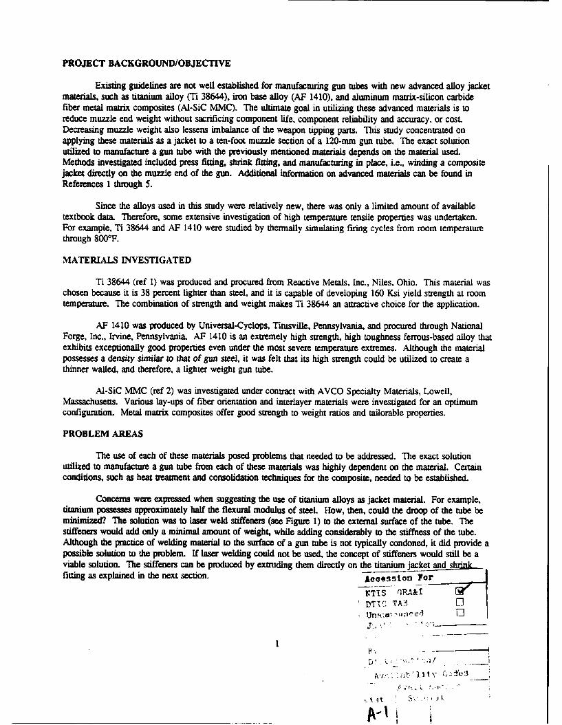
PROJECT BACKGROUND/OBJECTIVE
Existing guidelines are not well established for manufacturing gun tubes with new advanced alloy jacketmaterials, such as titanium alloy (Ti 38644), iron base alloy (AF 1410), and aluminum matrix-silicon carbidefiber metal matrix composites (AI-SiC MMC). The ultimate goal in utilizing these advanced materials is toreduce muzzle end weight without sacrificing component life, component reliability and accuracy, or cosLDecreasing muzzle weight also lessens imbalance of the weapon tipping parts. This study concentrated onapplying these materials as a jacket to a ten-foot muzzle section of a 120-mm gun tube. The exact solutionutilized to manufacture a gun tube with the previously mentioned materials depends on the material used.Methods investigated included press fitting, shrink fitting, and manufacturing in place, i.e., winding a compositejacket directly on the muzzle end of the gun. Additional information on advanced materials can be found inReferences 1 through 5.
Since the alloys used in this study were relatively new, there was only a limited amount of availabletextbook data. Therefore, some extensive investigation of high temperature tensile properties was undertaken.For example, Ti 38644 and AF 1410 were studied by thermally simulating firing cycles from room temperaturethrough 800*F.
MATERIALS INVESTIGATED
Ti 38644 (ref 1) was produced and procured from Reactive Metals, Inc., Niles, Ohio. This material waschosen because it is 38 percent lighter than steel, and it is capable of developing 160 Ksi yield strength at roomtemperature. The combination of strength and weight makes Ti 38644 an attractive choice for the application.
AF 1410 was produced by Universal-Cyclops, Titusville, Pennsylvania, and procured through NationalForge, Inc., Irvine, Pennsylvania. AF 1410 is an extremely high strength, high toughness ferrous-based alloy thatexhibits exceptionally good properties even under the most severe temperature extremes. Although the materialpossesses a density similar to that of gun steel, it was felt that its high strength could be utilized to create athinner walled, and therefore, a lighter weight gun tube.
Al-SiC MMC (ref 2) was investigated under cont-act with AVCO Specialty Materials, Lowell,Massachusetts. Various lay-ups of fiber orientation and interlayer materials were investigated for an optimumconfiguration. Metal matrix composites offer good strength to weight ratios and tailorable properties.
PROBLEM AREAS
The use of each of these materials posed problems that needed to be addressed. The exact solutionutilized to manufacture a gun tube from each of these materials was highly dependent on the material. Certainconditions, such as heat treatment and consolidation techniques for the composite, needed to be established.
Concerns were expressed when suggesting the use of titanium alloys as jacket material. For example,titanium possesses approximately half the flexural modulus of steel How, then, could the droop of the tube beminimized? The solution was to laser weld stiffeners (see Figure 1) to the external surface of the tube. Thestiffeners would add only a minimal amount of weight, while adding considerably to the stiffness of the tube.Although the practice of welding material to the surface of a gun tube is not typically condoned, it did provide apossible solution to the problem. If laser welding could not be used, the concept of stiffeners would still be aviable solution. The stiffeners can be produced by extruding them directly on the titanium jacket and s!nk__fitting as explained in the next section. AcoesSion For
riiTS_ qrA&IDTIC TA- l
I i1, ¢., i i,, , . - "

Another problem with Ti 38644 is its complex time and temperature heat treatment profiles and itsiucompatibility with gun steel. Gun steel is typically tempered in the 10000 to 1100°F range, while the titaniumalloy is an age-hardened material, typically aged at 900°F for 11 hours. This aging treatment would have adetrimental effect on the steel properties if the two were heat treated together after manufacturing. Therefore,the two materials need to be heat treated separately to their respective optimum levels. Such a complexity addsto the problem of machining because the materials need to be fully hardened prior to machining.
A negative feature when considering AF 1410 is that the density of the material is approximately thesame as the gun steel it will be replacing. Since the goal is to attain a lighter weight tube, why then would onereplace the gun steel with a material of the same density? Since the strength and toughness of AF 1410 aresuperior to that of gun steel, the possibility exists for a thinner-walled tube, and hence, a lighter weight tube.However, due to program cutbacks initiated at this stage of the project, the jacketed AF 1410 tube was nevermanufactured.
Many areas of concern were expressed when considering MMC. For example, how would an MMCjacket be fabricated on a steel liner? Two possible methods were investigated, shrink fitting and fabricating inplace. Unfortunately, both of these methods pose problems. Shrink fitting is difficult to accomplish because ofthe minimal coefficient of thermal expansion (CTE) of SiC. Since the CTE is minimal, the material must beheated to a higher temperature in order to attain the needed expansion. However, at higher temperatures, thealuminum will have a tendency to flow more easily, making thermal fabrication difficult. The second methodof fabricating the jacket on the steel liner also poses problems. MMC must be consolidated after fabricating inorder to reduce voids. Typically, consolidation techniques are done under high pressure and high temperature.As previously mentioned, the CTE of the Al-SiC MMC is magnitudes of times smaller than the steel portions.When the material is heated (during consolidation), the steel and MMC jacket expand, and the steel is actuallyforced into the MMC jacket. At this elevated temperature, there is intimate contact at the interface between thetwo materials. On cooldown the steel returns to its original dimensions, and all voids, etc. that were removedfrom the MMC during consolidation accumulate at the interface. This is an undesirable condition, since there isno contact at the interface after cooldown, and therefore, the load-canying capability of the tube is greatlyreduced.
APPROACH
Method of Manufacturing with Ti 38644
Traditionally, jacketed tubes have been produced by placing the jacket on a liner in order to providethick-walled sections and favorable residual stresses. The objectives of this project, as previously stated, are toaddress tube weight as well as tipping moment considerations. In the past, gun tubes have been shrunk fittogether by heating the jacket in a conventional oven until a desired temperature is reached. This temperatureprovides enough radial dilation of the jacket material to slide it over the liner. Once this temperature is reached,the jacket is wrapped in insulating material and transported to the liner, where they are shrunk together. Duringthe time when the jacket is removed from the oven until the actual shrink fitting takes place, a considerableamount of heat is lost from the jacket. This loss of heat causes the radial expansion of the jacket to decrease,and increases the potential for the jacket to "bind up" on the liner during manufacturing.
In order to minimize the possibility of "bind up," an induction coil shrink fit tower was designed (seeFigure 2). The apparatus utilizes induction heating as opposed to conventional oven heating. Also, the heatedjacket remains in place, that is, it does not need to be transported to the liner. As opposed to the hot jacketbeing transported to the colder liner, the colder liner is transported to the hot jacket. This minimizes any thermal
2

losses caused as a result of transportation, and maintains the desired amount of radial dilation needed formanufacturing. A uniform soak temperature was obtained by cycling the current on and off during heating. Thecyclic heating of the titanium jacket took approximately 4 hours (at 325 amps) to reach a temperature of 750°F.This temperature provided sufficient radial dilation of the jacket to easily slide over the liner. The method anddetails of the shrink fitting process are outlined in Appendix A.
Cold rotary forging the titanium jacket onto the steel liner was the second method of manufacturing withTi 38644 investigated. The text fixture in Figure 3 was designed so a full-size prototype could be forged. Sincethe CTEs (the time/temperature profiles) of steel and titanium are not compatible, cold rotary forging of the testfixture was accomplished at room temperature, as seen in Figure 4. During forging, a water bath was applied tothe woa qece to minimize any thermal effects caused by working. A 30 percent reduction in area wasaccomplished in a single pass on an SPF 55 GFM rotary forge. Property measurements were evaluated in thepre- and post-forged conditions, and are discussed below. Evaluation of the steel/titanium interface after coldrotary forging indicated that this method of manufacturing could not be used because only random contact wasmade at the interface. As mentioned earlier, if intimate contact is not made at the stee/titanium interface, theload-carrying capability of the composite tube is greatly reduced.
Previously, the concept of a stiffened tube was evaluated as a possible solution to the question offlexural stability. Under contract with EBTEC, Agawam, Massachusetts, several short tube segments werefabricated with stiffeners welded to them. During this contract, specific guidelines were to be established forlaser welding stiffeners to tube sections. The development of processing parameters was to commence with theproduction of a full-length (105-mm M68) all steel, proof-of-principle, L A S E R (Long Axially StiffenedExperimental Rifle) gun tube, Figure 1. A 105-mm tube was selected because of economic reasons and becauseEBTECs proposed workstation would have difficulty accepting the size and weight of a 120-mm tube.Specification LCB 8-85 was submitted and went out for quotation to procure a 5 kW, CO2 pulsed laser. Thelaser would be capable of welding, heat treating, cutting, and drilling. The specification received fourprospective bidders. However, due to ManTech Program cutbacks, a majority of the funding needed to purchasethe laser was reracted and the procurement action terminated.
Method of Manufacturing with Al-SiC MMC
Two methods of manufacturing with Al-SiC MMC were investigated. The first method involved pressfitting the MMC jacket onto the liner, followed by mechanical autofrenage. The contactor supplied a jacket thatwas three thousandths of an inch larger in inside diameter than the steel liner it was going to be pressed onto.Although the jacket was larger at the contacting interface than the liner, frictional effect and the fact that thejacket was not perfectly straight, dictated that it would need to be pressed rather than simply slid onto the liner.The liner and jacket were then aligned, and a hydraulic press was used in an attempt to press the two together.A lead-based lubricant was applied to the steel in order to minimize friction at the interface. Uponmanufacturing, the AI-SiC jacket was pressed several inches before binding on the steel liner. Further attemptsto continue pressing resulted in severe deformation of the Al-SiC jacket. This test proved that press fittingwould not be feasible at least under these conditions.
Manufacturing the Al-SiC in place (on a liner) was also investigated on fifteen small-scale prototypespecimens. In this method, the AI-SiC jacket was actually wound on the steel liner, and consolidation of theAI-SiC took place while the jacket was on the steel liner. As stated previously, a gap was created at thejacket/liner interface during consolidation. It was felt that autofrettage after consolidation would aid inminimizing or eliminating this gap. Although this did help to minimize the gap, it did not eliminate it. Twofull-scale prototype tubes were manufactured and fired at Aberdeen Proving Ground, Maryland. Because of the
3

difficulties encountered in manufacturing the fifteen small-scale prototypes (ref 2), both tubes were wrapped withonly hoop windings and no consolidation technique was utilize. The fifteen small-scale prototypes weremanufactured with various lay-ups of hoop and axial plies, as well as different plasma-sprayed interlayermaterials. These provided an array of manufacturing options that were evaluated for application to the full-scalemodel
Property Measurement of Ti 38644
Under contract with Rensselaer Polytechnic Institute (RPI), Troy, New York, Ti 38644 was exposed toelevated temperature tensile testing by a Gleeble Model 1500. The Gleeble machine was originally designed atRPI to investigate the thermal effects caused by welding, however, it simnulat the effects of thermal cyclingquite well. The results of high temperature tensile testing are outlined in Table 1 and are presented graphicallyin Figures 5 through 7. Both longitudinal and transverse samples were investigated. The data suggest that thematerial exhibits adequate strengths up to the maximum working temperature of 8000F. Charpy v-notch (CVN)specimens were also tested in this phase of the project. Samples were tested at -400F from the transverse andlongitudinal directions. Results of the transverse and longitudinal CVN testing indicated values ranging from 8.5to 10.5 ft-lbs. As mentioned above, the titanium alloy was cold forged to investigate rotary forging as a possiblemethod of manufacturing. Properties were measured to compare the pre-cold forged condition with the post-coldforged condition (ref 4). The ultimate tensile strength, yield strength, reduction in area, and CVN are outlined inTable 2 and shown graphically in Figures 8 through 11.
Property Measurement of AF 1410
AF 1410 was also studied under contract with RPI. The contract included investigation of tensileproperties at elevated temperatures, age-hardening response, and microstructure (ref 5). Test results indicate thatspecimen orientation has little or no effect on the ultimate tensile strength, yield strength, and true fracture stress;however, it does have a significant effect on the percent reduction in area and the true fracture strain. Thetemperature dependency of Young's modulus was also investigated for the transverse and longitudinal directions.Young's modulus was shown to be dependent on the specimen orientation (longitudinal higher than transverse)and test temperature. Results of high temperature tensile testing of AF 1410 can be seen in Table 3, as well asFigures 12 through 14. Age-hardening testing indicates that optimum aging response takes place after 6 hourswhen held between 800°F and 1000°F.
CONCLUSIONS
This study has concentrated on investigating three materials, Ti 38644, AF 1410, and Al-SiC MMC, forfuture use in cannons and cannon components. Several important conclusions can be drawn from this programas follows:
We have successfully demonstrated that induction coil shrink fitting can be utilized tomanufacture jacketed cannon tubes.
Although the impact strength of Ti 38644 is lower than desired, it can be used with areasonable degree of confidence as a jacket material.
Cold rotary forging of Ti 38644 is possible on the SPF 55 GFM rotary forge at WatervlietArsenal. This method of manufacturing is a viable way of producing a titanium jacket to nearnet shape. If rotary forging is considered for producing titanium jackets, additional work isneeded to assess the possibility of hot rotary forging, followed by heat treatment.
4

AF 1410 possesses extremely high strength and ductility and is ideally suited not only forjacketed tubes but also for a mono-block design. This material should be given specialconsideration in the future if a more advanced material than gun steel is desired for gun tubes.
Al-SiC MMC should also be considered as a candidate for a mono-block design. Its specialfeatures, such as high strength and low weight, make it extremely desirable for use in guntubes. Although this material has many good features, no successful method of manufacturehas been demonstrated. If this obstacle can be overcome, Al-SiC MMC should also be givenspecial consideration in advanced gun tube designs.
5
REFERENCES
1. R. Hasenbein, E. Hyland, and G. Cunningham, Titanium-Jacketed Cannon Tube Program, ARDECTechnical Report ARCCB-TR-89009, Benet Laboratories, Watervliet, NY, April 1989.
2. R. Hasenbein, E. Hyland, and G. Cunningham, Laboratory Tests of Metal Matrix Composite-JacketedCylinders, ARDEC Technical Report ARCCB-TR-91016, Benet Laboratories, Watervliet, NY,April 1991.
3. R. Hasenbein, G. Cunningham, and E. Hyland, Metal Matrix Composite-Jacketed Cannon TubeProgram, ARDEC Technical Report ARCCB-TR-91027. Benet Laboratories, Watervliet, NY,August 1991.
4. E. Troiano, Effects of Cold Forging on the Mechanical Properties of Titanium Alloy 38644, paperpresented at the 31st Mechanical Working and Steel Processing Conference, Chicago, IL,23-25 October 1989.
5. D.N. Peek and E.F. Nippes, Evaluation of Elevated-Temperature Mechanical Properties of AF 1410Steel for Ballistic Application, Rensselaer Polytechnic Institute Internal Report, Troy, NNY, May 1989.
6

Table 1. Results of High Temperature Tensile Testing of Ti 38644
Orientation Temperature Ultimate Tensile 0.1% Yield % Reduction(OF) Strength Strength in Area
(Ksi) (Ksi)
Transverse 77 161 134 14.3
Transverse 400 160 132 11.6
Transverse 600 158 127 9.8
Transverse 600 157 123 11.6
Transverse 800 141 96 27.8
Transverse 800 144 111 29.4
Longitudinal 77 180 157 10.8
Longitudinal 200 167 140 21.4
Longitudinal 200 166 152 17.2
Longitudinal 4ou 171 142 25.3
Longitudinal 400 155 131 13.5
Longitudinal 600 144 114 13.5
Longitudinal 600 144 138
Longitudinal 800 162 130 23.7
Longitudinal 800 140 106 26.0
7

Table 2. Comparison of Pre- and Post-Forging Mechanical Properties of Ti 38644
Orientation Ultimate Tensile 0.1% Yield % Reduction CVNStrength Strength in Area (ft-lbs)
(Ksi) (Ksi)
Pre-Forged Room Temperature Properties of Ti 38644
Longitudinal 179 161 14 9.0
Longitudinal 178 159 13 8.5
Longitudinal 180 162 12 8.5
Longitudinal 177 159 12 9.0
Longitudinal 183 168 8
Longitudinal 182 168 10
Transverse 181 164 5 9.5
Transverse 179 162 6 11.0
Transverse 185 168 6 10.5
Transverse 184 165 5 10.0
Transverse 179 168 7
Transverse 182 169 6
Post-Forged Room Temperature Properties of Ti 38644
Longitudinal 186 171 13 5.0
Longitudinal 193 177 13 5.0
Longitudinal 200 191 13 4.5
Longitudinal 191 180 10 5.5
Longitudinal 195 182 9
Longitudinal 198 186 9
Transverse 201 168 4 4.0
Transverse 188 152 10 4.0
Transverse 175 140 15 4.5
Transverse 179 145 13 4.0
Transverse 178 146 6
Transverse 189 155 11
8

Table 3. Results of High Temperature Tensile Testing of AF 1410
Orientation Temperature Ullmnate Tensile 0.1% Yield % Reduction(OF) Strength Strength in Area
(Ksi) (Ksi)
Transverse 77 256 205 66.4
Transverse 77 251 207 66.9
Transverse 77 253 210 66.8
Transverse 200 240 188 67.2
Transverse 200 235 194 67.0
Transverse 400 229 179 67.9
Transverse 400 220 181 67.4
Transverse 600 210 164 68.3
Transverse 600 208 160 67.7
Transverse 800 198 138 68.8
Transverse 800 201 144 67.7
Longitudinal 77 246 71.6
Longitudinal 77 244 194 70.6
Longitudinal 77 264 208 71.4
Longitudinal 200 232 181 71.8
Longitudinal 200 232 196 71.7
Longitudinal 400 220 191 72.8
Longitudinal 400 222 192 73.0
Longitudinal 600 208 164 73.1
Longitudinal 600 210 166 72.9
Longitudinal 800 196 72.9
Longitudinal 800 192 134 73.0
9

40
4L
100

Figure 2. Induction coil shrink fit tower.

4.0
122

Cu
0�
Cu
.5
S0
4)
13

U.0
0
.0
go
a.a
I-
LU 0
0I.- UU .
W) -a)
14

cnco
U..
0
*U U * U
w
0 49

CL,
U.U
CL_ _ _ _ _ _ _ __n_ _ _ _ _ _ _ _ .0
0j
Ao
0M
0a
w1

cia
c.c
0 0
cm C,,
I- ~17

Cl,
U...
z
UU
oeU
U N V- W
18

* 11 * 0 cc
(0
z
0 c
cu~0 0o c tc
* a19

* UL
0,
z
- I-C
CV))
UL-1 o
20

CO
IgI
m 0
mmb 0
co
LLU
0. >U. cc -5
-~ LUI- - 0.
CM.
U))
21

Cbcfo
010
co-
w C
LL LU<
I.-
40 0
CflM
00
49 8M Of
22~

0•0
z0
U cc0
Co
ww
go LLo
0- 0
0
ono
cLU
23.. a.j
0 -
U, 0
p *0
23

APPENDIX ATITANIUM SLEEVE SHRINK FIT
1. Raise titanium sleeve WTV-D31612 using a swiveled lifting device, lower and dhre-d into plate
WTV-D30672.
2. Lower induction coil WTV-F31363 into position around titanium sleeve and make necessary hookups.
3. Insert insulation blanket between induction coil and titanium sleeve.
4. Place circular water quenching device on top of induction coil for later use.
5. Raise carrier assembly Wr/-31365 using a swiveled lifting device, lower and thread into plateWTV-30673 (hold with crane until Part 6 is finished).
6. Place stabilizers WTV-31367 into position by sliding them into contact with carrier and bolting down.
7. Turn power to induction coil and heat titanium sleeve to 7501F.
8. When 750°F is achieved, turn off power to induction coil.
9. Raise liner WTV-F31610 using swiveled lifting device, align on carrier assembly until muzzle end isapproximately one inch above stabilizers.
10. Loosen bolts holding stabilizers and slide back as far as possible.
11. Lower liner into titanium sleeve until steel jacket WTV-31611 comes into contact with titanium sleeve.
12. Immediately water quench steel/titanium interface with previously mentioned water quenching device.
13. Quench until steel/titanium interface reaches 100"F.
14. Unthread titanium and steel liner as one piece and remove from induction coil.
24

TECHNICAL REPORT INTERNAL DISTRIBUTION LIST
NO. OFCOPIES
CHIEF, DEVELOPMENT ENGINEERING DIVISIONATTN: SMCAR-CCB-DA 1
-OC 1-0I 1-DR 1-DS (SYSTEMS) 1
CHIEF, ENGINEERING SUPPORT DIVISIONATTN: SMCAR-CCB-S 1
-so 1-SE 1
CHIEF, RESEARCH DIVISIONATTN: SMCAR-CCB-R 2
-RA 1-RE 1-RM 1-RP 1-RT 1
TECHNICAL LIBRARY 5ATTN: SMCAR-CCB-TL
TECHNICAL PUBLICATIONS & EDITING SECTION 3ATTN: SMCAR-CCB-TL
OPERATIONS DIRECTORATE 1ATTN: SMCWV-ODP-P
DIRECTOR, PROCUREMENT DIRECTORATE 1ATTN: SMCWV-PP
DIRECTOR, PRODUCT ASSURANCE DIRECTORATE 1ATTN: SMCWV-QA
NOTE: PLEASE NOTIFY DIRECTOR, BENET LABORATORIES, ATTN: SMCAR-CCB-TL, OFANY ADDRESS CHANGES.

TECHNICAL REPORT EXTERNAL DISTRIBUTION LIST
NO. OF NO. OFCOPIES COPIES
ASST SEC OF THE ARMY COMMANDERRESEARCH AND DEVELOPMENT ROCK ISLAND ARSENALATTN: DEPT FOR SCI AND TECH 1 ATTN: SMCRI-ENMTHE PENTAGON ROCK ISLAND, IL 61299-5000WASHINGTON, D.C. 20310-0103
DIRECTORADMINISTRATOR US ARMY INDUSTRIAL BASE ENGR ACTVDEFENSE TECHNICAL INFO CENTER 12 ATTN: AMXIB-PATTN: OTIC-FDAC ROCK ISLAND, IL 61299-7260CAMERON STATIONALEXANDRIA, VA 22304-6145 COMMANDER
US ARMY TANK-AUTMV R&D COMMANDCOMMANDER ATTN: AMSTA-DDL (TECH LIB)US ARMY ARDEC WARREN. MI 48397-5000ATTN: SMCAR-AEE 1
SMCAR-AES, BLDG. 321 1 COMMANDERSMCAR-AET-O, BLDG. 351N 1 US MILITARY ACADEMYSMCAR-CC 1 ATTN: DEPARTMENT OF MECHANICSSMCAR-CCP-A 1 WEST POINT, NY 10996-1792SMCAR-FSA 1SMCAR-FSM-E 1 US ARMY MISSILE COMMANDSMCAR-FSS-0, BLDG. 94 1 REDSTONE SCIENTIFIC INFO CTR 2SMCAR-IMI-I (STINFO) BLDG. 59 2 ATTN: DOCUMENTS SECT, BLDG. 4484
PICATINNY ARSENAL, NJ 07806-5000 REDSTONE ARSENAL, AL 35898-5241
DIRECTOR COMM4ANDERUS ARMY BALLISTIC RESEARCH LABORATORY US ARMY FGN SCIENCE AND TECH CTRATTN: SLCBR-OD-T, BLDG. 305 1 ATTN: DRXST-SDABERDEEN PROVING GROUND, MO 21005-5066 220 7TH STREET, N.E.
CHARLOTTESVILLE, VA 22901DIRECTORUS ARMY MATERIEL SYSTEMS ANALYSIS ACTV COMMANDERATTN: AMXSY-MP 1 US ARMY LABCOMABERDEEN PROVING GROUND, M4 21005-5071 MATERIALS TECHNOLOGY LAB
ATTN: SLCMT-IML (TECH LIB) 2COMMANDER WATERTOWN, MA 02172-0001HQ, ANCCOMATTN: AMSNC-IMP-L 1ROCK ISLAND, IL 61299-6000
NOTE: PLEASE NOTIFY COMMANDER, ARMAMENT RESEARCH, DEVELOPMENT, AND ENGINEERINGCENTER, US ARMY AMCCOM, ATTN: BENET LABORATORIES, SMCAR-CCB-TL,WATERVLIET, NY 12189-4050, OF ANY ADDRESS CHANGES.

TECHNICAL REPORT EXTERNAL DISTRIBUTION LIST (CONT'D)
NO. OF NO. OFCOPIES COPIES
COMMANDER COMMANDERUS ARMY LABCOM, ISA AIR FORCE ARMAMENT LABORATORYATTN: SLCIS-IM-TL 1 ATTN: AFATL/MN2800 POWDER MILL ROAD EGLIN AFB, FL 32542-5434ADELPHI, MO 20783-1145
COMMANDERCOMMANDER AIR FORCE ARMAMENT LABORATORYUS ARMY RESEARCH OFFICE ATTN: AFATL/MNFATTN: CHIEF, IPO 1 EGLIN AFB, FL 32542-5434P.O. BOX 12211RESEARCH TRIANGLE PARK, NC 27709-2211 MIAC/CINDAS
PURDUE UNIVERSITYDIRECTOR 2595 YEAGER ROADUS NAVAL RESEARCH LAB WEST LAFAYETTE, IN 47905ATTN: MATERIALS SCI & TECH DIVISION 1
CODE 26-27 (DOC LIB) 1WASHINGTON, D.C. 20375
DIRECTORUS ARMY BALLISTIC RESEARCH LABORATORYATTN: SLCBR-IB-M (DR. BRUCE BURNS) 1ABERDEEN PROVING GROUND, MO 21005-5066
NOTE: PLEASE NOTIFY COMMANDER, ARMAMENT RESEARCH, DEVELOPMENT, AND ENGINEERINGCENTER, US ARMY AMCCOM, ATTN: BENET LABORATORIES, SMCAR-CCB-TL,WATERVLIET, NY 12189-4050, OF ANY ADDRESS CHANGES.