Embed Size (px)
Citation preview

SOCIALIST REPUBLIC OF VIETNAM Ministry of Industry and Trade (MOIT)
Technical Regulation Volume 3
Construction and Installation of Power Network
(Final Draft for Revision)
(Updated)
June 2013
Japan International Cooperation Agency
Electric Power Development Co., Ltd. Shikoku Electric Power Co., Inc.
West Japan Engineering Consultants, Inc.
IL
CR(2)
13-099

Table of Contents CHAPTER 1 GENERAL ................................................................................................................... 1
CHAPTER 2 GENERAL PROVISIONS ......................................................................................... 2 Section 1 General .......................................................................................................................... 2 Section 2 Industrialization of Construction and Installation Practices ......................................... 3 Section 3 Preparations for Construction and Installation Practices .............................................. 4 Section 4 Requirements on Construction Works for Installation of Electrical Equipment ........... 8 Section 5 Technology and Automation for Power Installation Work ............................................ 9
CHAPTER 3 INSTALLATION OF POWER DISTRIBUTION SYSTEM AND SUBSTATIONS ......................................................................................................... 12
Section 1 Installation of Power Distribution Systems................................................................. 12 Section 2 Power Transformers .................................................................................................... 16 Section 3 Gas Insulated Switchgear (GIS) .................................................................................. 16 Section 4 Panels and Boxes ........................................................................................................ 18 Section 5 Secondary Circuits ...................................................................................................... 19 Section 6 Stationary Battery System ........................................................................................... 21 Section 7 The Capacitors to Improve the Coefficient ................................................................. 22 Section 8 Fire Prevention Measurements .................................................................................... 22
CHAPTER 4 ELECTRICAL LIGHTING EQUIPMENT ............................................................ 25 Section 1 General ........................................................................................................................ 25 Section 2 Lights .......................................................................................................................... 25 Section 3 Equipment of Lighting Systems .................................................................................. 27 Section 4 Distribution Boards ..................................................................................................... 28
CHAPTER 5 EARTHING SYSTEMS ............................................................................................ 29 Section 1 General ........................................................................................................................ 29 Section 2 Laying Earthing Wires ................................................................................................ 31 Section 3 Earthing Distribution Equipment ................................................................................ 33 Section 4 Earthing Power Equipment ......................................................................................... 33 Section 5 Earthing in Circuits and Cable Lines .......................................................................... 34 Section 6 Methods of Painting and Marking............................................................................... 35
CHAPTER 6 METHOD OF LAYING WIRES AND CABLES ................................................... 36 Section 1 General ........................................................................................................................ 36 Section 2 Laying Wires on Insulating Stands (Pulleys, Insulators) ............................................ 38 Section 3 Suspended Wires ......................................................................................................... 40 Section 4 Laying Protective Cables and Rubber-Insulated Cables ............................................. 40
i

Section 5 Open and Underground Layout of Conductor............................................................. 42 Section 6 Underground Wires in Non-Metal Sleeves ................................................................. 45 Section 7 Laying Underground Wires in Glass Pipes ................................................................. 48 Section 8 Open and Underground Layout of Conductor in Steel Pipes with Thin Wall ............. 50 Section 9 Wires Bare and Covered with the Voltage Less than 1kv ........................................... 53 Section 10 Terminals Marking and Jointing with Insulators and Cables ...................................... 53 Section 11 Laying Wires in Inflammable and Explosive Rooms.................................................. 55 Section 12 Painting and Marking .................................................................................................. 57
CHAPTER 7 UNDERGROUND CABLE LINES ......................................................................... 57 Section 1 General ........................................................................................................................ 57 Section 2 Installation Cable in Cable Trenches........................................................................... 59 Section 3 Required Dimensions for Installation ......................................................................... 59 Section 4 Cable Installation inside Culvert, Canal and Production Area .................................... 60 Section 5 Cable Installation inside Block and Pipe .................................................................... 61 Section 6 Cable Installation at Swamp, Muddy Region and Under Water ................................. 62 Section 7 Cable Connection and Cable Head Making ................................................................ 63 Section 8 Cable Installation in Explosive Room and Explosive Outdoors Equipment............... 64 Section 9 Painting and Marking .................................................................................................. 66
CHAPTER 8 OVERHEAD POWER TRANSMISSION LINES ................................................. 66 Section 1 General ........................................................................................................................ 66 Section 2 Foundation Works ....................................................................................................... 69 Section 3 Installation and Poles Erection .................................................................................... 71 Section 4 Installation of Insulator and Wiring Accessories ........................................................ 72 Section 5 Installation of Conduction Wire and Lightning System .............................................. 73 Section 6 Numbering and Painting ............................................................................................. 74
ii

List of Tables
Table 96 Motion direction of the steering wheel or the crank on the actuating system of the disconnector and circuit breakers ........................................................................................ 14
iii

CHAPTER 1 GENERAL
Article 1. Purpose
This Technical Regulation defines the necessary terms and procedures for the construction and installation of power projects.
Article 2. Scope of application
The stipulation in the Technical Regulations shall be applied to the construction, installation and repair of electric facilities for network of its voltage up to 500kV.
Article 3. Definitions
The following definitions apply to this technical standard.
1. “Authority” represents the Ministry in charge or organizations authorized by the Ministry in charge with specified competence in construction and repair of technical facilities or electric facilities connected to the national grid.
2. “The Owner” means any agency, organization, individual, or joint-venture thereof that owns power plants and has a legal responsibility for the operation of those power plants.
3. “The Consultant” represents any agency, organization, individual, or joint-venture that is committed to be in charge of design of construction or repair work by the Owner.
4. “The Contractor” represents any agency, organization, individual, or joint-venture that is successful tender of construction or repair work and often plays a role of practical enforcement of them.
5. The Sub-contractor” represents any agency, organization, individual, or joint-venture that is committed to be in charge of practical enforcement of construction or repair work by the Contractor.
6. Design materials” represents essential design documents including instruction of construction or repair work for contractors or sub-contractors to proceed their work accurately.
7. “Prefabricated Method” represents the use of electrical equipment that is assembled in the factories in advance.
8. “Phase identification” represents phase color allocation, where phase A is yellow, phase B is green, and phase C is red.
9. “The testing cable” represents control cable for lines, busbar, generation facilities, and so on. Its main role is sending signals such as switching on or off to circuit breakers and others related to controlling power system.
1
CHAPTER 2 GENERAL PROVISIONS
Section 1 General
Article 4. Scope of application
These regulations are applied to the construction, repair and installation of electrical equipment with voltage up to 500kV.
Article 5. General provisions
These provisions are legal documents which are compulsory for application. Power designers, contractors and acceptance agencies of power construction works as well as equipment suppliers and equipment manufacturer must strictly follow these provisions.
Article 6. Technical conditions and methods
Technical conditions and methods other than what stipulated in this technical regulation could be adopted, only if certain level of safety can be ensured by other conditions and methods that have adequate technical evidence.
Article 7. Applicable related regulations
During the installation of electrical equipment, the work shall be done in accordance with the following items.
(1) These technical standards
(2) The present construction standards and rules
(3) The rules for safety in construction, the requirements for safety-working as well as for prevention of fire, and explosion
(4) The design proposals approved by the authorities, manuals from manufacturers
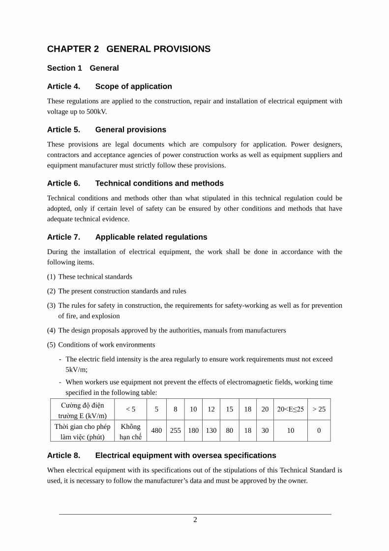
(5) Conditions of work environments
- The electric field intensity is the area regularly to ensure work requirements must not exceed 5kV/m;
- When workers use equipment not prevent the effects of electromagnetic fields, working time specified in the following table:
Cường độ điện trường E (kV/m)
< 5 5 8 10 12 15 18 20 20<E≤25 > 25
Thời gian cho phép làm việc (phút)
Không hạn chế
480 255 180 130 80 18 30 10 0
Article 8. Electrical equipment with oversea specifications
When electrical equipment with its specifications out of the stipulations of this Technical Standard is used, it is necessary to follow the manufacturer’s data and must be approved by the owner.
2

Article 9. Requirements for qualifying persons
For types of work such as: the installation of batteries, welding, binding, installation with pneumatic and drop hammers used or other installation tools etc, only qualified persons who are trained and have mastered the technical rules, procedures for technical process and safety rules shall be employed.
Article 10. Construction site patrol
Construction site patrol means that Engineering Manager shall patrol the construction site according to the construction progress. Engineering Manager shall confirm the compliance for Technical Regulation and the proper condition for the construction. If an Engineering Manager would find an inappropriate condition, he/she should give proper instructions to improve and adjust it. Additionally, Engineering Manager should be the engineer who knows the Technical Regulation / Guideline and management of construction.
Article 11. Site quality management training
Site quality management training means that an Engineering Manager shall conduct training for all workers before starting construction from the view point of improving quality and safety at the worksite.
Additionally, an Engineering Manager should explain to all the workers about outline of construction works, the important points of work quality and the safety measure against the expected dangers.
Section 2 Industrialization of Construction and Installation Practices
Article 12. Accelerated adoption of industrialized methods
During electrical construction, it is essential to apply industrialized methods as much as possible. This means the use of newly developed construction method and prefabricated method as well. Electrical equipment must be installed into sets, into blocks, in clusters at the processing plant before installation.
Article 13. Computerization of design materials
Designs for electrical installation and construction practices shall be computerized as much as possible.
Article 14. Construction steps
Practices of electrical construction and installation must be followed the two steps below:
Step 1: all construction structures relating to the later installation of electrical equipment must be finished.
Step 2: combined electrical equipment, shall be installed into blocks or in clusters. The installation practices of electrical equipment must be implemented with construction methods approved by authorities.
3

Article 15. Assembling process
For construction structures of assembly, parts to be assembled shall have slots, gaps, hollows for junction boxes, and holes to install conductors in accordance with requirements in design materials.
Article 16. Installation of bus bars
Prefabricated construction methods should be applied to the installation of conductors (both indoor and outdoor) in each cluster in assembly or processing plant as much as possible.
Article 17. Encouragement of prefabricated methods
All the construction and installation production of heavy duty equipment such as conductors, bus bars, and distribution equipment shall be made in factories
Article 18. Test, adjust the measurement mounted on construction equipment
The metering and counting equipment shall be tested at factories during in installation practices.
Article 19. Grounding stakes and their accessories
Grounding stakes and its accessories of grounding systems shall be prefabricated and manufactured in factories.
Article 20. Poles
Poles for overhead lines shall be prefabricated in processing and manufacturing factories
Section 3 Preparations for Construction and Installation Practices
1. Requirements for design materials
Article 21. Design materials
Design materials shall comply with state requirements in terms of designs and estimates of industrial structures
Article 22. Design documents for agencies in charge of installation site
Design material for agencies of installation practices must receive approval from relevant agencies.
Article 23. Applied conditions to the design materials
Design materials for agencies of installation practices shall have a official document of applied conditions.
4

Article 24. Regulation for content, procedures of construction design materials
If the owners do not make construction design materials by themselves, they shall hire a consultant or other professional agency. Components and content procedures of construction design materials as well as installation plans must be implemented in accordance with present state requirements.
Article 25. Design consultancy works
Consultants that make construction design materials are required to meet the deadlines of the installation practices.
Industrialization and new techniques shall be applied at the highest level in order to successfully complete the duties, reduce necessary work force and its cost.
Article 26. Hand over materials
An owner shall provide manufacturer’s design materials to the contractors, sub-contractors, or successful tenders.
(1) Documentation of the construction drawing design by consultancy company for this project.
(2) Technical materials (record or passport) of machines, accessories and meters of complete equipment.
(3) Assembly drawings of electrical equipment and complete equipment, complete equipment diagrams for principles and assembly.
(4) List of all items attached to equipment or accessories
(5) Manufacturers’ manuals methods of installation and start-up of electrical equipment. Manufacturers’ certified documents of assembly, balance tests, initial run, and checking and taking over the equipment.
(6) Profiles must be clearly mentioned in manufacturers’ assembly and test trials at testing blocks (test bed).
Article 27. Foreign manufacturer’s design
Foreign manufacturer’s design materials, if any, shall be translated into Vietnamese and the required number of these documents shall be handed over to successful tenders.
2. Requirements of equipment supply
Article 28. Materials from manufacture
The owners are required to ensure that contractors obtain design materials from manufacture.
Article 29. Electrical equipment supply for power of construction
Provide electrical equipment in order to have pre-installation of electric supply systems, it is necessary to give priority to pre-supply of electrical equipment and required materials.
5

3. Procedures and conditions for acceptance, maintenance, and handover of electrical equipment as well as construction and installation materials
Article 30. Process of hand-over of electrical equipment
Sequence and condition of receipt and preservation of electrical equipment, cable accessories and materials stored must follow the manufacturer’s instruction.
Article 31. Unloading equipment
Blank storages, indoor storages and yards for keeping electrical equipment must have enough facilites of loading and unloading to move the equipment.
Article 32. Checking at handover process
When handing over equipment, it shall be checked in accordance with inspection regulations.
Article 33. Equipment in warehouse
Electrical equipments in warehouse must be kept in a safe place and convenient for transportation and installation. If symbols or marking is faded or missing, it is required to re-check before installation.
Article 34. Classification of equipment at yard
It is required to hang the signboard with clear indication of name of item group of electrical equipment in the preservation place, if equipment is placed in outdoor yard, it is required to put the pile for hanging the above signboards. The weight must be clearly indicated on large and heavy equipments (counted in tons).
Article 35. Outdoor storages (store openings)
Equipment must be placed on racks in yards or blank stores to avoid contacting with the ground.
In outdoor or semi-outdoor stores, equipment must be arranged and protected from stagnancy of water and the damp.
Large and heavy components and equipment must be arranged so as to avoid deformation. Equipment is placed fixed to avoid downfall and breakdown.
Article 36. Indoor storages (sealed storage)
Indoor storages that storage the vulnerable devices for the environment should be taken care as follows. Electronics devices such as relays and digital meters, electrical panel needs to be stored in closed warehouses fitted with air conditioning if it is long-term storage.
Article 37. Condition of stored equipment
Electrical equipment must be kept in clean, dry and well-ventilated place. Electronics devices such as relays and digital meters should be stored carefully. Equipment must be protected to avoid noxious fumes and carbon dust. Racks must be rust-proofed.
6

Article 38. Preservation of capacitor
Static capacitors, oil soaked capacitors must be preserved in dry indoor place at temperature not higher than +35deg C. Do not preserve capacitors in warehouses affected by vibration (such as near working machines). When capacitors are kept in house with dryer, it is required to avoid placing them near heat generating sources and being directly exposed to the sunlight. Capacitors must be vertically placed, porcelain insulator must be turned upwards, and not be piled one stack to another.
Article 39. Preservation of battery
Lead storage battery plates must be preserved in package and placed in dry indoor place, alkaline storage batteries must be kept in dry and ventilated indoor place (without dramatic change in temperature). It is prohibited to place lead storage batteries together with alkaline storage batteries.
Article 40. Maintenance of equipment in warehouse
When the electrical equipment is kept in warehouse for a long time, it is required to consider and open periodically for maintenance and lubricate according to a definite term and technical condition of manufacturer. The above work shall be carried out at least every 9 months.
The above-mentioned work shall be carried out in house to avoid dirt and dust on equipment.
Article 41. Delivery Units Responsibilities
Units in charge of transportation (delivery) shall be responsible for reporting in writing for defects and failures of the equipments.
Article 42. Preservation of metal structure
Metal structures of overhead line poles, steel poles, precast concrete poles, and accessories must be preserved and arranged according to each type, at each separate place, and must be supported by pallet or board to avoid the damp.
Article 43. Sort by category
Forging items, bolts and accessories of overhead lines must be divided into each category and placed in warehouse. It is required to ensure good water drainage, threads of bolts, and forging items to be lubricated by oil.
Article 44. Damaged equipment in warehouse
Damaged items must be separated to settle and avoid wrong supply.
Article 45. Storage of Conductor and insulators
Conductors and insulation porcelains must be divided into description of marking and preserved in yard with good water drainage system.
7

Article 46. Storage of Cement
Cement provided must be packed. Cement storage must have roof and floor which must be hollowed under the floor for ventilation. It is not allowed to place cement with different brand and of different lots in the same place.
Cement discrete is poured into the container with each different label.
Article 47. Storage of Explosive materials and warhead
Storage of explosive materials and warhead type of guns used for construction and installation must comply with the regulations on preservation and transportation of explosive materials.
Section 4 Requirements on Construction Works for Installation of Electrical Equipment
Article 48. Plan preparation before installation of equipment
Before installation of electrical equipment at construction worksite, it is required to carry out preparation works as follows:
(1) Construction of permanent and temporary roads. The road must be wide enough for transportation of electrical equipment (including heavy duty equipment), types of materials and components for installation at place of installation and position of installation shall be considered for the maintenance.
(2) Construction of temporary office and tents for installation of electrical equipment;
(3) Installation of temporary and fixed gas compression, water supply and power system as well as equipment for connecting them with construction machines;
(4) Construction of roads for fire engines, installation of pipes and equipment necessary for firefighting;
(5) Installation of ladders and scaffoldings at positions where cranes can not be operated;
(6) Ensuring drinking water supply.
Article 49. Preparatory order of construction
Power supply works (transformer, cable tunnel) and cranes must be installed before starting main construction works.
Article 50. Works inspection and acceptance report
Reports on inspection and acceptance of buildings and works must be implemented by construction companies, Contractors, or Sub-contractors for installation of electrical equipment in compliance with the regulations of these standards.
Article 51. Basis for acceptance of works
Acceptance of works shall be carried out based on approved design document.
8

Article 52. Acceptance of order
When acceptance of building work, machine, equipment foundation, pole, beam, cable trough, etc. are carried out, it is required to check dimension and quality of structures built according to the design documents that have been approved.
Article 53. Prefabricated construction items
Construction of storage for of pre-assembled distribution equipment such as control panel, electrical board, underground transformer room and other electrical chambers must be carried out before installation.
Construction items must be completed by ensuring safety and not affecting installation of electrical equipment. Protection for electrical equipment is required during the period of installation so as to avoid rain, sunlight, underground water and dust, damage and failures due to continual completion of construction works.
Article 54. Appropriate size of hole on wall and conduit
Size of inlets of conduit chambers and holes on wall, ceiling, etc. must be conformed the design document, and comply with equipment installation option.
Article 55. Underground part of electrical projects
All underground parts in concrete structures of overhead lines or transformer, must have sufficient technical data, technical acceptance record in accordance with the design document before installation to a certain position.
Article 56. Installation of construction machines
For the installation of electrical equipment relates to installation of other types of machines, it is required to install them according to the suitable schedule.
Article 57. Other items in the design document
The pipe boxes, ducts, recesses for installing conductors and electrical equipment including telecommunication equipment are indicated in the design document, the installation must be carried out during construction.
Article 58. Machine foundation
Machine foundations completed for installation of machine must be inspected before installing them, and the related report shall be handed. by sub and main contracting agencies.
Section 5 Technology and Automation for Power Installation Work
Article 59. Assembly at workshop
Assembling units in fabrication workshop should be carried out on mounting bracket.
9

Article 60. Welder
Welders of mounting platform in overhead must have sufficient standard of stipulated professional qualification
Article 61. Installation of main busbars
Installation of main busbar should be carried out by crane and with fixed supports
Article 62. Working overhead without crane
When working overhead without crane, it is necessary to use moveable platforms with guard rails.
Article 63. Tensioning of electric wire
When tensioning electric wire, especially wire with large cross section, it is better to use special winch or machine to have enough tensions.
Article 64. Transportation of large equipment
Transportation of large equipment in control rooms such as switch board and built-in distribution equipment, it is better to carry out by special lifting equipment
Article 65. Installation of electric switchboard and cubicles
Installation of electric switchboard and cubicles should be carried out by crane, pulley or winch, etc.
Article 66. Transportation and preservation of high voltage oil soaked insulators
Discharging, moving and preservation of high voltage oil soaked insulators of transformers must always be kept in vertical state.
Article 67. Installation of earthing equipment
Installation of earthing equipment should be done by using special machines and means used for pile driving. When it is necessary to have deep earthing holes, it is better to use steel drilling head.
Article 68. Transportation of transformer
It is possible to transport transformer with rated capacity of up to 1,000kVA by truck or special means of transport in combination such as sliding carriage and trailer, etc.
Normally, transformer with rated capacity over 1,000kVA must be transported by railway. When there is no railway, it is possible to use trailer together with tractor. It is required to use suitable load crane to lift and load transformer on the foundation. When there is no crane, it is required to use lifting jack, tie pulley and hoist or hauling winch to move a transformer to the foundation.
Article 69. Installation of electrical equipment
It is necessary to use crane or other lifting means for the installation of electric equipment. If it is impossible to use crane, it is allowed to use winch and lifting jack.
10

Article 70. Discharging and transportation of cables
Discharge and transportation of reels and cables should be carried out by special means of transportation. It is better to use crane to discharge cable reels.
Article 71. Cables crossing railway and national road
When cable lines cross railway or national road, it should use method of penetration excavation or use transverse boring machine (if any).
Article 72. Construction of underground cables
All construction of cables should be mechanized.
Article 73. Mechanization in construction of transmission line
For construction of transmission line, it should be mechanized for discharge, transportation, earthwork, installation and other heavy work as much as possible.
For construction of electric wire, specialized installation wires should be used.
Article 74. Transportation of concrete poles
Transportation of concrete poles is to be ensured safety and good quality.
Article 75. Construction of pole foundation
The equipment or vehicle which can drill and put up a pole can be utilized. As a concrete pole is heavy, it should be handled carefully.
Article 76. Construction of pole foundation in rocky mountainous areas
It is better to use steam hammer, drill, blasting, etc. for constructing areas where the soil is mixed with many rocks.
Article 77. Installation of electric poles
It is better to use mechanized method for installation of poles. It is prohibited to bind cables on bar to lift poles.
Article 78. Anchor poles when pulling wire
During wiring installation between the first two poles, temporally anchor must be ensured to prevent from turnover the poles.
Article 79. Construction of steel tower
When jointing steel tower, it is better to use crane or climbing crane.
Article 80. Laying conductor and earthing wire
It is better to use truck, tractor or hoist to lay conductor and earthing wire.
11

CHAPTER 3 INSTALLATION OF POWER DISTRIBUTION SYSTEM AND SUBSTATIONS
Section 1 Installation of Power Distribution Systems
Article 81. Scope of application
All the requirements in this chapter are applied to installation of indoor and outdoor electrical equipment for power distribution systems with voltage from 1,000V to 500kV.
1. General requirements
Article 82. Installation of equipment
Equipment and busbars shall be securely fixed with weld, bolts, compression, etc.
Article 83. Oil level in the equipment
Oil in the equipment shall be filled up to the level as indicated by the manufacturer.
It is not allowed that oil leaks through welds, flanges, joint valves, taps, joints, oil indicators, etc.
2. Joining the busbars of the indoor distribution equipment
Article 84. Conducting busbars
The busbars shall be stretched, and shall not be warped and cracked at location where busbars are bent.
Article 85. Fixation of the busbars
The busbars can be expanded along its axis according to the temperature change. Thus, it is required to fix the busbar on the insulator in consideration of this thermal contraction and expansion.
Article 86. System fixing the busbars
All the fixtures of the busbars and their cramps shall not be formed a magnetic circuit around the busbars. So one of cramps or all the bolts on one side of the busbars must be made by non-magnetic materials (brass, aluminum and its alloy, etc.) or it is necessary to apply the type of fixing the busbars which does not form a closed magnetic circuit.
Article 87. The Joints of the busbars
Regarding the joints of busbars, it is required to have sufficient strength against vibration from the equipment connected, own gravity of the conductor, wind pressure, electromagnetic force generated between conductors at the time of short-circuit fault, etc.
The joints of busbars shall be used weld, bolts or compression joint.
The joints of busbars are required not to be greater than the resistance than the busbar.
12

3. The installation of busbars of the outdoor distribution equipment
Article 88. The bending deflection of the flexible busbars
The bending deflection of the flexible busbars may be deviated ±5% from the design materials.
Article 89. The Flexible busbars
On the whole length of the flexible busbars, it is not allowed to have any wrings, twists, chips, nicks or any damaged separated line.
Article 90. Jointing of the hard busbars with poles of the equipment
During joining the hard busbars with poles of the equipment, thermo-expansion shall be considered.
Article 91. Jointing of the flexible busbars with poles of the equipment
When flexible busbars or their branches are jointed, and when they are jointed to poles of the equipment, types of clamps or caps shall be suitable for the line's cross sections and materials.
Article 92. Joints of busbars
When jointing busbars, it is necessary to take countermeasures against corrosion at the joints including bolts, nuts, and washers in consideration of the environment. When jointing different metals, such as aluminum busbar and copper busbar, it is necessary to take countermeasures against electric corrosion at the joints.
Article 93. Install distribution system outdoors
The outdoor installation of distribution equipments must comply with the following requirements:
(1) Equipment must be placed on a level plane at minimum height of 0.3m, and it is at least 0.5m for electrical panel.
(2) In electrical cabinets, if it is needed, on-site drying out must be enabled in order to ensure normal operation of the components, relays, measuring tools and electric meters which shall be followed by the Vietnam Standards.
4. Circuit breakers of the voltage 1kV or more and their transmission systems
Article 94. Inspection of circuit breakers
The transmission system of circuit breaker and all other practical systems shall work smoothly and precisely after the adjustment according to manufacturers manual. The installation shall be done according to manufacturers manual.
5. Disconnector and its transmission system
Article 95. Disconnectors
The transmission system of disconnectors and all other practical systems shall work smoothly and precisely.
13

Disconnectors and accompanied equipment shall be fixed securely in accordance with article 82.
Article 96. Actions close-cut
When operating the disconnector and the circuit breaker, the steering wheel of the transmission system (lever type) shall have the motion direction as shown in the following table.
Table 96 Motion direction of the steering wheel or the crank on the actuating system of the disconnector and circuit breakers
Operation Direction of motion Steering wheel Crank
Switching on Clockwise Going up or to the
right Going up or to the right
Switching off Counterclockwise Going down or
to the left Going down or to the left
Article 97. Actuating detent
Detent parts in the actuating system with the disconnector of three phases shall be operated smoothly, precisely and reliably. In the end positions, actuating system must be stopped automatically.
Article 98. Adjustment for disconnector
The state of contact when the disconnector is closed shall be adjusted appropriately according to the manufacturer's manual.
Article 99. Signaling and locking transmission system
Angles of the contact of actuating systems for signaling and locking transmission, the position of a disconnector shall give the signal of cutting after the blade has passed 75% of its whole way and only give the signal of switch on when the blade has touched the fixed contact jaw.
Article 100. Interlock
It is necessary to interlock between disconnector and circuit breaker as well as between main blade and grounding blade of a disconnector.
6. Instrument current transformers
Article 101. Short-circuit ends of wires unused
Ends of wires unused for secondary windings in current transformers need to be short-circuited. In any case, (except cases indicated in designs) one terminal of the ends of the secondary windings in current transformers of the circuit with the voltage of at least 500V as well as it of voltage transformers shall be grounded.
14

7. Prefabricated distribution equipment and compact substations
Article 102. Requirement for boxes’ doors
Boxes' doors shall operate smoothly and require locks. Every compartment shall have enough keys for all boxes.
Article 103. Specifications of compact switchgear cubicle
The specifications of all equipment of compact switchgear cubicles shall comply with technical requirements and manufacturers' manual.
8. Painting and Markings
Article 104. Painting and markings
Painting shall be carried out appropriately for the purpose of corrosion prevention in consideration of the environment.
Warning signs shall be displayed at a dangerous place appropriately in consideration of safety.
Equipment number signs, color of phases must be presented in accordance with the provisions. .
Do not paint the location to measure temperature earthing and mounting joints mobile. The charged portion connected by bolts painted only after complete installation to ensure conductivity.
9. Installation of compartment
Article 105. Corridor in electrical room
In electrical compartment (see Chapter I.1 – Volume I), operation control corridors in front and at the back of electrical panel board must satisfy the appropriate specifications.
Article 106. Installation of meshwork fence
In order to protect bare live components, it is allowable to use meshwork fence according to the IEC 60529.
In the compartment that non-electrical workers can enter, all live components must be fenced up with tight boards.
Removable type fence must be securely fastened in order that it cannot be removed without specialized tools. Doors must be locked by a key.
The detail of protective barrier is stipulated in the article 333 of Vol.1 of Technical regulation.
Article 107. Outlet in the room of the distribution equipment
If length of distribution panel board is up to 7m, one outlet must be installed. If the length is over 7m, two outlets must be installed on two sides.
It is not mandatory to build the second exit in case that operation corridor is wider than 3 m and there is no oil-filled equipment in the electrical compartment.
15

Article 108. Installation of Ending parts of conductor and cable
Ending parts of conductors and cables must be stored inside the equipment.
Section 2 Power Transformers
Article 109. Scope of application
The requirements in this section are used for the installation of transformers (including autotransformers and oil-filled induction coils) with the voltage up to 220kV.
Article 110. Dryness of transformers
It depends on the manufacturer's requirements and insulator standards of transformers whether or not the transformer is dried, and must keep a record with representatives of assembly and contract agencies involved.
Article 111. Arrangement of expansion compartment
The expansion compartment shall be cleaned dirt and rinsed with clean transformer oil
The layout in the expansion compartment shall be arranged so that nearby cable ends, conductor bars, and equipment are not splashed with oil when a problem arises.
Article 112. Transformer fixation
It is necessary to chock steadfastly all of the transformer's wheels.
Holder of the transformers directly on the foundation must be necessary to chock steadfastly all of the wheels.
Article 113. Prevention from flood and collapse
Distribution systems and substations must be built in accordance with in-force regulations on construction in order to avoid being flooded or collapsed down or etc. under the current regulations.
Article 114. Signing transformers
Transformers and accompanied equipment shall be painted and signed in accordance with article 104.
Section 3 Gas Insulated Switchgear (GIS)
Article 115. Scope of application
The requirements in this section shall be applied to all installation works of GIS.
Article 116. Condition of assembling work of GIS
In order to prevent water condensation inside the equipment, infiltration of foreign substance into the equipment, etc., assembly work of GIS for outdoor substation shall not be carried out in the rainy weather and strong wind.
16

However, if a rain-cover and countermeasures against dust are set adequately in working area, and temperature and humidity are kept adequate with dry air, it is acceptable to carry out assembly work regardless of weather.
Article 117. Against dust during the assembly work
During the assembly work, countermeasures against dust such as dustproof partition, dustproof net and dustproof sheet shall be taken sufficiently.
Article 118. Apparel for worker
Worker shall wear dustproof uniform, cap, and shoes. They shall be non-conductive for preventing adhesion of metal fiber due to static electricity.
Article 119. Check before starting assembly
Before starting assembly and connection work, besides cleaning the inside of a tank, the following points shall be checked:
(1) Breakage in flange surface and spacer;
(2) Drop-off of bolt and pin inside the tank;
(3) Adhesion of foreign substance or stain to the conductor, protrusion on the conductor;
(4) Scratch, peeling of plating, etc. on the contact;
(5) Scratch on the surface where O-ring is fitted.
Article 120. The time of unit connection
At the time of unit connection, centering shall be carried out so that internal conductor is connected appropriately without excessive load.
Article 121. Grease for the connecting part
Conductive grease shall be applied to the connecting part of conductors and, grease for seal shall be applied to the surface where O-ring is fitted and airtight surface.
Article 122. Tightening bolts Use of torque wrench
When tightening bolts, torque wrench shall be used.
Article 123. The duration of exposure of adsorbent to atmosphere
The duration of exposure of adsorbent to the atmosphere (from the time the seal is broken until the time of producing vacuum) shall not exceed 30 minutes.
Whenever a tank is vacuum drawing or opened, the absorbent shall be changed to a new one before filling it up with SF6 gas.
Article 124. Making vacuous and filling up SF6
Before filling up SF6 gas, the tank shall be fully vacuumed.
17

Article 125. SF6 gas analysis
One or two days after filling up of SF6 gas, SF6 gas analysis shall be carried out.
Article 126. SF6 gas leakage test
After filling up SF6 gas, SF6 gas leakage test shall be carried out.
After checking gas leakage by implementation of airtight test, waterproofing process shall be performed to the sealing parts.
Article 127. Gas valves in SF6 gas tank
When extracting SF6 gas from the tank, gas valve shall be operated after confirming gas partition with gas distribution diagram so that the gas may not be extracted from the other tank.
At the end of the work, gas valves shall be checked to be in the appropriate state according to the gas distribution diagram.
Article 128. SF6 gas recovery
When extracting SF6 gas from the tank, gas recovery equipment shall be used, and the gas shall not be emitted outside.
Article 129. Inspection of GIS
Every component of GIS shall be inspected according to the contents of Vol.5.
Section 4 Panels and Boxes
Article 130. Scope of application
The requirements in this section are used to assemble the boxes and plates and accompanied equipment.
1. Assembly of structures, meters, equipments and busbar systems
Article 131. Earthing non insulated systems to cubicle cover
Metal equipment, which is not insulated from the boxes or the plates used to fix equipment and the main pipes, is required to be connected to cubicle cover.
Article 132. Rubber mattress for a number of equipments
The circuit breakers, self-recording meters, and the high sensitive relays shall be put on the elastic mattress rubber.
Article 133. Installation of disconnector and fuse
The disconnectors are required to be installed in order to ensure that blades of them work smoothly and tightly.
18

Article 134. Protection for charged parts
When the electric equipment, clip used to connect wires, and the wires that have 380V/220V of voltage are located on the shelf next to the equipment with the voltage lower than 220V, it is required to protect all of the electrically charged parts to avoid being touched by people. It is also required to warn the danger in different colors.
Article 135. Fitting of switches
The assembling of switches, starters from conductor bars of the secondary circuit and groundings of the boxes and panels are required to follow the design specifications.
Article 136. Connection of the equipment and the busbars of the cubicle
Equipment and busbars of a cubicle as well as the main conductors and the branch conductors shall be connected in accordance with Article 87 and 92
Article 137. Fixation of switchgear
Bolts and split screws used to fix switchgear of a cubicle compartments are required to be measured to avoid being loosened naturally.
2. Painting and signing
Article 138. Painting panels and accompanied equipment
The panels, boxes and accompanied equipment shall be painted and sighed in accordance with article 104.
Section 5 Secondary Circuits
Article 139. Scope of application
The requirements in this section are widely adopted for electric wire installation of the control circuits, measurement circuits, protection circuits, transmission, and signal circuits. This means the applications are for all of the secondary circuits that are put in the compartments of distribution equipment, control boxes and panels.
1. Electric wires
Article 140. Installation of wires and cables
When the electric wires and passing cables are laid, it is required to meet the following requirements:
(1) For concrete walls or stone walls, it is required to cover these wires and cables by steel pipes or insulated pipes or pass the wires through the holes that are surrounded by an iron box.
(2) For the metal box compartments, it is required to put the wires and cables into insulated pipes or brushlooked rods.
19

(3) For the insulated box compartments, it is acceptable to put directly the wires and the cables on their surfaces.
Article 141. Wires connection of wires to the oil-filled equipment
The wires connecting to oil-filled equipment (i.e. gas relays) are required to have an insulated layer that is not damaged by oil and have a protection in order to avoid physical damages.
Article 142. Connection to crips
The multi copper core wires and cables connected to clips and equipment shall have heads and rings. It is acceptable to curve the cables' edge into ring shape in order to weld it.
Article 143. Extra length of wires and cables
It is required to have an extra length in each wire or cable core so that it can be reconnected in case the wires are broken.
Article 144. Use of soft-copper core wires
In case of wires passing through the doors or other opening-closing doors (box doors), it is required to use soft-copper core wires.
2. The rows of the clips for wire connection
Article 145. For distribution equipment above 1kV
The clips for wire connection of the distribution equipment must have the voltage of 1000V or above. The group of contacts of circuit breaker and disconnector shall be arranged so that the primary circuit will not be cut off during the maintenance.
Article 146. Condition of the clips for wire connection
The clips for wire connection shall not be damaged, dusty or rusty, and shall be securely fixed. The rows of the clips for wire connection the box compartments of the distribution equipment are required to be covered by boxes.
3. Markings
Article 147. Secondary circuit
The wires of the secondary circuit shall be connected to the clip rows, to the contact points of meters, equipment in accordance with cable splicing map.
Article 148. Materials used at the ends of wires
The small plates at the ends of wires for notations and the pipe for covering the wire heads shall be made from insulating materials.
20
Section 6 Stationary Battery System
Article 149. Scope of application
The requirements in this section are applied to the installation of sealed lead acid storage battery and sealed alkali battery.
1. The conductor bar system
Article 150. Materials of the conductor bars
The conducting bars made from steel, copper or aluminum shall be used.
Article 151. Fixation of the conductor bars
The conducting bars shall be securely fixed with the pulleys or insulators.
2. The installation of batteries
Article 152. Cells of batteries
The conducting bars, branches and cells of batteries shall be securely connected in accordance with article 87 and 92
Article 153. Installation of Battery System
Stationary battery system must be placed in a separate compartment or cabinet. It is allowed to place several battery systems in the same compartment. If battery is placed in enclosed room or compartment, these compartments must comply with appropriate specifications, and proper ventilation system must be installed.
Article 154. Transportation of Battery
During the transporting process, batteries must be kept stable with the ventilating. Additionally, all the actions related to the installation, operation, maintenance and safety of the battery must be done by following specific instructions and requirements of its manufacturer.
Article 155. Ventilation System of Battery
The compartment of acid battery where discharging process is implemented must be equipped with permanent compulsory ventilation system. The battery compartment where sub-charging operation is regularly done must be equipped with permanent compulsory ventilation system, or portable system shall be accepted if the charging is finished or over-charging testing.
Additionally, natural ventilation system must be utilized as well in order to ensure the exchanging of air volume of the compartment at least once in every one hour.
In case the natural ventilation system is not sufficient for the air exchange, then compulsory system must be utilized.
21

Article 156. Leak of electrolyte solution
The vessels of lead acid storage batteries and alkali storage batteries shall not leak electrolyte solution.
Article 157. Charging procedures for batteries
The charging procedures for the lead acid storage batteries and alkali storage batteries shall comply with the manufacturer's manuals. The batteries must not be overcharged.
3. Painting and marking
Article 158. Painting and marking
The batteries and accompanied equipment shall be painted and signed in accordance with article 104.
Section 7 The Capacitors to Improve the Coefficient
Article 159. Scope of application
The requirements in this section are applied to the installation of the groups of oil paper insulating capacitors or each capacitor tank in order to improve the capacity coefficient of alternating current machines with the frequency of 50Hz and voltage up to 10kV.
Article 160. Grounding of capacitors
The grounding of the capacitors shall comply with the requirements in Chapter 5, Earthing Systems. As a special caution, each cover of the capacitors shall be grounded by connecting the cover to the stand for the capacitor or to the grounding line.
The grounding wires shall be arranged in a way that it is convenient to replace the capacitors during operation.
Article 161. Painting and marking
The capacitors shall be painted and signed in accordance with article 104.
Section 8 Fire Prevention Measurements
Article 162. Floor of the compartment for transformers
Floor of the compartment where an oil-filled transformer is installed must have gradient downwards to the oil-collecting sump according to the requirement of the transformer.
Article 163. Door (gate) of transformer compartment
Door (gate) of transformer compartment must satisfy the requirements described in Vol.1, Chapter 4-2-1.
22

Article 164. Equipment in transformer compartment
In the compartment where transformer is installed, it is allowed to place blade-type disconnect switch, disconnector on load, fuse, circuit breaker, lightning arrester, arc suppression coil and cooling equipments which belong to that transformer.
Article 165. Exit to the outside in transformer compartment
Every compartment of oil-filled transformer must have its own exit to the outside or to the adjacent compartment where floor, wall, partitions are fireproof and explosion-prone or inflammable equipment and materials are not available.
Article 166. Horizontal distance from door in transformer compartment
Horizontal distance from door of transformer compartment in adjoining substation or indoor substation to the nearest window or door in the same compartment must be not less than 1m.
Article 167. Ventilation system of transformer compartment
Ventilation system of transformer compartment must be capable of discharging the heat radiated by transformers (see Vol.1, Chapter 4-2-2). It is not allowed to connect with other ventilation systems.
Article 168. Ventilation pipe of transformer compartment
Ventilation pipe of the transformer compartment adjoined to other house, where the walls are fireproof but the roof is made of inflammable materials, must be placed at least 1.5m away from walls or separated by a barricade wall that is made of nonflammable materials and at least 0.6m higher than the roof of the house.
Article 169. Compulsory cooling system in inside transformer
Compulsory cooling system installed inside transformer must be automatically controlled over its start-up and pause.
The cooling system must be automatically started up according to the temperature of the uppermost of oil layer or load current value of the transformer Windings.
Article 170. Cooling system installed apart from transformer
Cooling system installed away from transformer so that it will not cause obstacle when moving the transformer out of the platform, and its repairing can be implemented while the transformer is operating. Heating air discharged from the cooling system must not flow towards the transformer’s body.
Article 171. Valves of the cooling system
Valves of the cooling system must be arranged in good places to be reached. The cooling system must be installed in good way in order that it can be removed from transformer or disassembled into parts, and the moving of the transformer might not require discharging oil out of the cooling system.
23

Article 172. The exposed oil pipeline of the cooling system
The exposed oil pipeline of the cooling system must be made of stainless steel or corrosion resistant materials.
The oil pipelines run near the transformer must not hinder the operation and maintenance of the transformer and the cooling system as well. Also, the pipelines must be placed so that it will not take much effort when it is required to move the transformer. Upon needs, necessary standing board and ladder should be installed to facilitate the approach to valves and blowers.
Article 173. Inspection of oil and water pump
For the inspection of oil pump and water pump of the compulsory cooling system, pressure gauge must be installed in every pump. If pump is equipped with filter, pressure gauge must be placed in both input and output of the filter.
Article 174. Foundation of the cooling system
Single type or double type cooling system that is arranged into a bank apart from transformer must be placed on the same foundation.
Group type cooling system can be placed directly on the foundation or on rails if it can be moved on wheels.
Article 175. Resistant of vibration of control panel board
It shall be allowed to mount control panel board on the body of transformer if the panel is resistant to vibration caused by the transformer.
Article 176. Alarm signal of compulsory cooling system
Transformer with compulsory cooling system must be equipped with alarm signal for emergency cases such as: oil circulating system, cooling water system or flower is halted, alarm automatic backup cooling system or backup the reserved power source.
Article 177. Absorbing of compulsory cooling system
Absorbing cylinders attached in the compulsory cooling system for cleaning transformer oil must be placed indoors if required by the manufacturer. The absorbent must be able to be replaced on site.
Article 178. Electric drying system
Electric drying system must be installed in the engine cabinet of the under-voltage regulator.
Article 179. Nitrogen containing flexible bags
Nitrogen containing flexible bags used for protecting transformer oil must be shielded from sunshine.
Article 180. Consideration of repairing of the transformer
If transformer is placed outdoors along the installation compartment of the power plant, it must be ensured the possibility of transportation to the repairing area without necessary actions such as:
24

disassembly of the transformer, removing the porcelain parts of the inlet, or removing structure supporting to conductors, gantry, etc.
CHAPTER 4 ELECTRICAL LIGHTING EQUIPMENT
Article 181. Scope of application
Installing electrical equipment for indoor and outdoor lighting systems shall be conformed to these current regulations.
Section 1 General
Article 182. Terminal of cables and wires
Terminals of cables, and copper and aluminum-unit wires connected to equipment, cubicles, lamps, etc. must comply with rules given in this chapter and chapter 6(Methods of laying wires). Terminals of wires connected to equipment, cubicle and lamps shall have a short section available for reconnection in case wires are broken.
Article 183. Structure parts of lightning equipment
Structure parts of lighting equipment such as stands, hooks, boxes, rods as well as fixed components, etc must be plated or painted for rust prevention.
Section 2 Lights
Article 184. Requirement for installation of lights
It is required to check installation of lights with wires and pre-determined heights given in the design materials. When installing lights in places where architectural structures exist with patterns and aesthetic decoration, etc, it is essential to comply with requirements given in the design materials.
Lighting directions of lights must be downward if there are not particular requirements of the design materials.
Article 185. Strength of structures of lighting equipment
Fixed structures of equipment must be computed to stand the weight of five times equipment’s weight as well as to stand the suitable weight with a standing person on it to do installation and maintenance. For the stand or poles that hang up decorated chandelier, it is necessary to add the weight of 80 kilograms.
Article 186. Adjustment of headlight
Each headlight must be adjusted its focus according to shapes of light spots on a vertical plate. If the vertical plate is not available, take light spots’ shapes in horizontal plates in condition that light’s body
25

is sloped to the largest angle, then re-corrected sloping angle and light according to the design materials. The headline shall be fixed firmly into revolving parts.
Article 187. Lights of hermitic types and dust prevent types
The lights such as hermitic type lights, dust prevent type and other similar types of lights, if they do not have caps, must have holes with washers for passing wires through. The hole must be stuffed up hermetically with pads.
Article 188. Installation of lights in explosive room
Lighting equipment in the explosive room must be explosion-proof. Lights in a explosive room must be installed securely with close washers. Bolts and nuts with thimble-bolt etc. must be tightened. The places through which wires pass must be stuffed hermitically and fixed suitably with light’s structure.
Article 189. Connection of lights to wires in doors
When connecting lights with wires in houses, public houses, or manufactories, it is essential to use coupling clips.
Article 190. Earthing Light’s body
For grids that require earthing light’s body with neuter wires, it must not be connected to phase wires. These stipulations are not for mobile belongings and table lamps (because they shall be connected by male plugs).
For earthed neuter wires, earthing of light’s body is implemented as follows:
(1) When wires are laid on the surface, the earth wires between lamps and neuter wires shall be flexible wires and the grounding point shall be on the closest fixed post of the lamp.
(2) When wires with insulating covers are laid in a steel duct fixed into light’s body at the specialized part, light’s body shall be connected with neuter wires at the light.
Article 191. Wire at lamp socket
The points where wires pass through shall be prevented from being damaged. Contact points of lamp socket must not be mechanically forced.
Article 192. Prohibition of connection of wires inside stands and ducts
It is prohibited to connect wires inside stands or ducts used for lamp installation.
Article 193. Rods for hanging lamps
Rods for hanging lamps must be made from steel ducts which have suitable width in order to bear mechanical forces, and it must be fixed firmly into lamp’s stands.
Article 194. Wires supplying for public lights
Wires supplying for public lights must be flexible wires with the cross section of 0.4mm2 for indoor lights, and 1 mm2 for outdoor lights.
26

Article 195. Insulation of wires supplying for lightning equipment
Wires supplying for lighting equipment must have insulation that can bear the alternating voltage of 500V and the direct voltage of 1,000V.
Article 196. Wires used for local lightning equipment
For wires used for local lighting equipment which are placed in fixed structures, it shall be two flexible cooper wires with cross sections of 1mm2 or above.
Article 197. Use of hermetic washers
Holes which the wires and cables pass through to lights and outdoor equipment must have hermetic washers.
Article 198. Lighting equipment on cranes
Lighting equipment on shaken facility such as cranes is required to be hung up by its resilient parts.
Article 199. Light for prevent of explosion
In places which inflammable, explosive and dangerous materials are placed (including indoor and outdoor), it is required to prevent people from touching with wires, lamp socket and light bulbs by accident.
Indoor metal lights hung on fixed metal hooks are required to have insulating ring cushions.
Section 3 Equipment of Lighting Systems
Article 200. MCCB and fuses
Step-down voltage MCCB and control-button fuses shall be connected into the grids so that, the other side of fuses or MCCB will be dead when the buttons are unbound.
Article 201. Arrangement of light switches
Point switches shall be placed on alley side of a house (inside or outside) but must be arranged in the way that they will not be hidden when the door is opened. Switches placed in a bath-room or restroom must be outside of the door.
Article 202. Installation of electricity meters
Electricity meters placed on boards or cubicles must be fixed securely. The height of the meters must follow standard designs.
Article 203. Laying wires on the surface of equipment
When wires are laid on the surface, equipment must be placed on the insulating plates whose thickness is at least 10 mm in case the structures of equipment do not have the special supports for installing directly to the wall.
27

Section 4 Distribution Boards
Article 204. Requirement for installation of distribution boards
It is required to place a distribution board in a steel cubicle that has locks and steel doors or it with joined glasses. Also, the holes where wires pass through must be hermetically sealed. This requirement applies to the following objects:
(1) Boards that are installed in an electric room and laboratory.
(2) Boards that are placed at the height of 2.5 meters and above (this excludes boards placed in an elevator or house).
(3) Boards in the cubicles which is partly made from steal.
(4) Boards with the electricity meter installed in houses.
(5) Boards that are placed in niches.
Article 205. Place the Board between current-carrying parts
When boards are placed between current-carrying bare parts and non-current caring metal parts, it is required to make certain that the minimum clearance distance of 20 mm for insulating faces, and 12 mm for gaps.
It is required to make certain that the distance between light bulbs and coupling points is large enough so that power shuts down in mobile parts of cut-out equipment when they are in the off position by checking connection diagrams.
Article 206. Locations for connecting input and output to distribution boards
Connection points to input and output to the boards must be installed at the locations that are convenient for testing and maintenance. Boards with contact points placed in the back must be hinge types. .
Article 207. Positions for wires passing to cubicles
Holes through which wires pass to steel cubicles and drawers with conductor materials shall have insulated bolted ducts.
Article 208. Painting and signing
The boards shall have notations indicating: signs, board’s functions and signs of outputs. When there are different phases of electricity, it is required to have clear signs and different color paints for each phase.
Article 209. Equipment connected to distribution boards
Connecting equipment to boards shall be in accordance with the design materials. Load shall be equally distributed between phases.
28
CHAPTER 5 EARTHING SYSTEMS
Article 210. Earthing requirement
When setting up the earthing systems for alternating and direct equipment, it is required to comply with stipulations given in this chapter.
Section 1 General
Article 211. Grounded in positions explosive, explosive devices
In explosive rooms and outdoor installation, it is necessary to comply with additional requirements
(1) Alternating installation with the voltage more than 42V AC and more than 110V DC must be earthed.
(2) It is essential to use bare wires or specially insulating covered wires for earth wires as well as neuter wires when earthing. Exploiting other structures such as rafter pipes, metal covers (except aluminum covers of cables) and leaden covers of cables etc. is only considered as an additional method.
(3) Main grounded lines must be coupled to earthed objects at least two points and should be connected at gable of the house.
Article 212. Parts to be earthed
Parts that must be earthed are as follows:
(1) Covers of electrical machines, transformer, equipment, , etc.
(2) Static parts of electrical rotational instruments.
(3) Secondary wire’s coils of measurement alternating machines.
(4) Frames of distribution cubicles, control cubicles, boards and others.
(5) Metal structures of transformer substations and outdoor distribution equipment, metal covers of cable cubicles, and cable’s metal covers (including testing cables and wires), metal pipes on which wires are passed through and etc.
(6) Blocking fences, nets or plates made of metal to protect conductor parts, girders, and beams, floors made up of metal and other parts that are electrified.
(7) Metal and concrete reinforced poles of overhead lines. Earthing of structures shall be conformed by requirements of the design materials.
Article 213. Objects not needed to be earthed
Objects that do not need to be earthed are as follows:
(1) Spare parts and equipment set up on a wooden pole of overhead lines and on the wooden structures of outdoor transformer substations if protective requirements are not essential to prevent from exceeding the voltage of atmospheres. These substations are as follows:
29

a. Spare parts of hung insulators.
b. Insulating stands.
c. Stands, light’s rod and lamp shades.
(2) Equipment placed on a metal structure that is earthed but their contact faces between equipment and these structures must be cleaned and not be painted.
(3) Covers of a meter and relay etc. set up on a board, cubicle, and the wall of distribution equipment.
(4) Rails in an electrical plant, substations and industrial manufactories.
(5) Parts that are normally removed or opened such as at distribution cubicles, fences, cubicles, doors as well as metal frames etc., which are already earthed.
(6) Electrical instruments with duplicate insulation.
Article 214. Replace earthing of equipment
It is possible to replace earthing of each engine and other equipment placed on main machines by directly earthing the machine’s body, but it is required to make certain the good contact between the equipment body and the base.
Article 215. Earthing of equipments
Safety grounding system, grounding work system, lightning grounding system must be connected to the grounding grid by separate branch wire. Allows each serial grounding system with many elements required together with a grounding wire to the grounding grid.
Article 216. Adopting objects as earthing equipment
When earthing, if the necessary resistance is satisfied, it is possible to adopt objects as earthing equipment such as:
(1) Water pipes and other metal ducts that are installed underground, except liquid fuel pipes, explosive gas pipes.
(2) Pipes for watering.
(3) Metal structures of construction works that are installed partly underground.
(4) Metal blocking plates of irrigational works, etc.
(5) Leaden cover of a cable that are laid underground (except that aluminum covers of cables must be insulated from the ground). In case that cable’s cover is the only object for earthing, at least two cables are required.
Article 217. Connection of Natural earthing and mainly earthing system
Natural earthing devices must be connected with mainly earthing systems at more than two different points.
This requirement is not applied to repeating earthing of neuter wires and cable’s metal covers.
30

Article 218. Digging, fill grounding system
Earthing devices should be installed underground. These devices are made up during executing bases of civil and industrial construction works. This stipulation is the same as that of overhead lines.
Excavation, fill earthing system must satisfy the technical requirements.
Section 2 Laying Earthing Wires
Article 219. Materials used for earthing system
Grounding conductor and grounding pole are normally used with steel wire or copper wire, aluminum wire, but the use of long-term durability must be taken into account. Ground wire and grounding pole shall be hot dip galvanized steel.
Using aluminum bare wires that are fixed in the ground for earthing devices or wires is prohibited.
Minimum size of grounding conductors and neutral conductor are decided according to the article 576 of Technical regulation Volume 1.
Article 220. Earthwires of mobile electrical tools
Earthwires of mobile electrical tools must be in the common cover with phase wires and have the same cross section as that of phase wires.
Units of wires and cables that are used for mobile tools must be flexible and have minimum cross section of 1.5mm2.
Article 221. Protection of earthwires
Earthwires must be protected from mechanical and chemical influences. At the locations where earthwires cross over cables, pipelines, rails and other places that can cause mechanical failures, it is all required to have protective methods.
Article 222. Earthwires in trough-wall
Earthwires at through-wall places must be located in niches, ducts or devices with hard covers.
Article 223. Coupling of earthwires
When coupling earthwires, it is essential to make certain that contact points are in good condition. The best way for it is solid welding.
Connecting neuter lines of circuits and overhead lines could be done in the same way as methods of connecting phase lines.
In rooms which are wet and have noxious (eroding) gases, connections of wires should be done by welding. In case welding is impossible, it could be done by using bolts, The contact surface of the plate bolted shall be two times of cross-sections of the grounding wire and junctions must have a protective coating.
31

Article 224. Connection of earthwires with long earthing devices
Connecting earthwires with long earthing devices (such as water pipeline or steel structural of construction) is done outdoor by welding or tightened by bolts . Places of installing collar with pipe must be cleaned.
Connecting locations and methods must be selected so that it still ensures necessary earthing resistances by using convenient methods when pipes are removed to be repaired. Water meters, valves, etc. must have earthed sections.
Article 225. Bare earthwires
For bare earthwires that are exposed, they could be laid vertically, horizontally or paralleling with slope structures of rooms. For earthwires whose cross section is rectangular, it is essential to place flatten faces parallel with faces of the structures. On the wires’ sections that are laid directly, it shall not be bended at zigzag places, and bare earth wires should be covered with insulated material in order to avoid persons touching them.
Article 226. Earthwires on concrete or brick plates
For earthwires that are laid on concrete or brick plates, it is required to fit tightly on a stand that is at least 5 millimeter away from the wall in a wet room, and 10 millimeter in a room which have eroding gas. In dry rooms without eroding environment, it is possible to lay earthwires made of flatten steel on concrete or cast iron plates. To fix earthed bars, using nails with special guns will give high productivity.
In gutters, earthwires must be placed at least 50mm away from the back of concrete plates. The distance between earthwire’s stands in direct sections shall be 600-1000 mm.
Article 227. Wires intersecting with gutters
When wires are laid openly indoor intersect with gutters (at the locations where mobile heavy weights pass by), wires must be protected securely from any mechanical damages.
Article 228. Temporary connection with mobile earthwires
Plates or corners to connect temporarily with mobile earthwires must be cleaned.
These plates or corners must be welded with earthwires or earthed with metal structures of main bar systems on distribution cubicles and outdoor substations.
Article 229. Soil for filling cable trenches
Soil used for filling up cable trenches must not be mixed with stones and rubbish.
Article 230. Prohibition of use of water pipelines
It is prohibited to use water pipelines to feeding troughs and milking equipment in livestock feeding camps for earthing.
32

Article 231. Use of welding or bolts
Coupling earthwires with earthed structures must be done by welding. However, when connecting earthwires with covers of equipment, electrical machines, etc., it is possible to use weld or bolts to fit tightly. At unstable places, it is required to have protective methods from the phenomenon of removing bolts by themselves (such as using braking bolts-nuts or cushion rings).
Article 232. Contacting faces of connecting places
Contacting faces of connecting places of earthwires and structures and equipment, etc. must be cleaned.
This requirement must also be done with faces of equipment’s cover, controlling rods, mobile parts and other parts of equipment, placed on steel structures, drawers, steel frames of distribution equipment, and stands, etc.
Notes: (1) To avoid emission of wastes, steel ducts to make manmade earthing should not be used . Angle or
round steels should be used.
(2) The minimum diameter of earth wires must also be applied to neutral lines of the networks and these of overhead lines to be used for earthing. At that time the diameter of neutral lines with single wire must be the same as that of phase lines.
Section 3 Earthing Distribution Equipment
Article 233. Earthing for distribution equipment
All equipment racks, bracket of the device, cover panel must be connected to the main earthing grid. The number of grounding wires of each device to the main earthing grid shall be in accordance with the design of the grounding system. Grounding of each device is subject to requirements by the equipment manufacturers. Grounding system for each device can be placed directly on the device or on the insulators.
Earthwires that are made up of steel must not be connected to form closed circuits around equipment
Section 4 Earthing Power Equipment
Article 234. Earthing for machines on sliding stands
When machines are placed on sliding stands, it is required to connect earthwires with these stands for earthing. Contacting faces between machine and stands must follow the requirements in Section 2, Laying Earthing Wires.
Article 235. Earthing of instrument machines
To earth instrument machines (main machines, etc), earthed wires or steel ducts must be connected with the cover. At that time, it is required to ensure the good energization between equipment’s cover and instrument’s cover, including duct’s connection points.
33

Equipment placed on mobile parts of machines must be energized by using flexible cables earthed by a dedicated core in these cables.
It is possible to use rails and girders of cranes in factories as earthwires for equipment of cranes.
Article 236. Earthing of rail cranes
Rail girder cranes that are used for earthing equipment of crane indoor or outdoor (except the explosive rooms) must be firmly earthed with earthing systems at two points. In the connection points of crane’s girders, it is essential to use flexible butt welding links to ensure short-circuit.
In rooms which have non-conductive dusts (such as cements, ash, soil to make patterns etc.), it is essential to place brushes in front of wheels of cranes to remove dusts out of rails before cranes start moving.
Section 5 Earthing in Circuits and Cable Lines
Article 237. Earthing of metal covers
After earthing metal covers of cables, metal covers and steel bands are connected, it should be coupled with the cubicle’s covers, cable funnels and connection boxes by flexible cooper wires. It is not necessary to use earthwires of which conduction is larger than that of cable cover.
Article 238. Use of aluminum cover
In installation that exploits aluminum cover of 3-unit cables for neuter wires, it is required to follow requirements of installing neuter lines.
Article 239. Terminal with earth wires
The terminal of earthwires must be installed by pressing or welding.
Article 240. Earthing of flexible links
For earthing flexible links, a steel wire must be used at the one end, tied tightly with steel cover and bands, and then welded. The other end shall be connected to earthed cables and metal structures by bolts.
Connection points of links with aluminum cover of cables must be coated with asphalts, goliptan paint or oil paints after welding. In the wet rooms and tunnels as well as gutters, welding points must be coated with hot bitumen.
Cross sections of flexible links must be commensurate with those of earthwires of the installation.
Article 241. Use of steel conduits
Steel conduits through which wires are passing are used for earthing devices or to earth securely. When these conduits are laid openly, it is possible to use coupling conduits that are coated with lead or other structures with good contacts.
34
When these conduits are laid underground, only the coupling conduits that are coated with lead shall be used. To ensure the electrical continuity of earthing circuits, following requirements must be satisfied:
(1) In any case that wire passes through conduits and cases that there are earthed neutral grids but conduits are laid openly, it is required to weld additional points on sides of coupling conduits. It is possible to weld metal links that are conductible enough.
(2) For connectors of conduits with boxes, instrument and equipment covers, it is required to use “couple bolts nuts” for earthing or apply other methods to ensure good contacts or to connect with boxes, such as cubicles, covers, by weld metal links with enough conductance.
Article 242. Lighting grouped grids
In lighting grouped grids, using metal covers of wires passing through conduits or wire’s leaden covers for earthwires is prohibited. In rooms which require the earthing of these covers, they must be earthed securely for their whole lengths.
Sleeve and terminal boxes must be coupled with metal cover of pipes by welding or bolts.
Article 243. Supplying or distribution cubicles
Metal cover of pipes, leaden cover of cables must be earthed with grouping, supplying or distribution cubicles by twisted cooper multi-unit wires whose cross section is 1.5-2.5 mm2 or by steel collar clipped tightly with earthed covers or butt welding into covers.
Article 244. Joint of earthwires with metal covers
For joint earthwires with metal covers of boxes, cubicles and boards, etc, they are required to be welded or used screws. In case the screws are used, the connected point must be cleaned.
Section 6 Methods of Painting and Marking
Article 245. Protection of grounding wire
In places where earthwires pass through into rooms, marking is required for easy differentiation.
Article 246. Painting of earthing system
All the Earthwires laid openly, structures, wires as well as flatten steel bars of earthing grids must be painted in black, except neuter lines.
Earthwires laid openly could be painted in other colors suitable to the color of the wall, but at least two black lines must be drawn 150 mm apart at such places as joints and branch joints.
Article 247. Use the bare earthed wires
Before installing bare earthed wires that are laid openly with fixed parts, all sides of wires expect welding point must be cleaned and painted. The joint points are painted after welding is done.
In rooms which are wet and have eroding gases, it is essential to paint by corrosion proof types.
35

Article 248. Places Joints with mobile earthwires
At places jointing with mobile earthwires, it is required to mark by painting the wall with letters of “earthing” and earthing symbols.
Article 249. Earthing devices and underground earthing
It is not essential to paint earthing devices and wires that are laid underground. After checking and taking over, welding points must be coated every side with bitumen.
CHAPTER 6 METHOD OF LAYING WIRES AND CABLES
Article 250. Scope of application
The requirements in this chapter shall be applied to indoor and outdoor installation of power and lighting lines with the direct and alternating voltage up to 1,000V by insulating wires and cables without steel covers and of which cross section is small.
Section 1 General
Article 251. Wires stipulated by the design materials
Styles, cross section and types of wires shall be stipulated by the design materials in accordance with the load and location.
Article 252. Insulation of cable joints
Joint and branch points of a wire and cable shall not bear mechanical pressures. Joints and branch joints of cable’s core and wires must be insulated and thermal insulated equivalent to insulation and thermal insulation of intact places.
Article 253. Use of terminal and distribution boxes
It is required to use terminal and distribution boxes for joint as well as branch wires in hermitic boxes, in sleeves and flexible pipes when the wires are laid openly or underground.
Structures of terminal and distribution boxes must be suitable for methods and environment of laying wires.
Internal boxes shall have lids. Conduits must be connected with branching wires by special clips with the insulating cover.
Article 254. Protection of wires at the output of boxes, conduits
The output area of boxes, conduits, hard ducts and flexible metal pipes, wires must be protected from any damage. In the places where wires cross over elastic joints, it is required to use elastic materials’ complement.
36

Article 255. Height of installation wires
There are no requirements of the height of installation above the floor for insulated wires, wires in pipes with the insulated metal cover, wires and cables passed through steel pipes and flexible metal pipes as well as flexible cables under heavy conditions. In the places where wires and cables may be damaged by mechanical forces, additional protective methods are required.
Article 256. Wires in high temperature place
When laying wires near high temperature pipes, the wires and cables must be protected from the heat or they must be suitable type to bear the heat.
Article 257. Terminal boxes set up vertically or upside down
When terminal boxes are set up vertically or upside down, it is required to fix them tightly.
In the case that earthing is required indoor, boxes and conduits must be laid to form an uninterrupted circuit for its whole length.
Article 258. Wires laid openly
Wires that are laid openly must be combined with the architecture of the houses to ensure the aestheticism.
Article 259. Wires in wet rooms
Length of wires placed on wet rooms (toilet, bathroom, etc.) must be as short as possible. Wires should be laid outside of these rooms and lights should be placed near wires on the wall.
Article 260. Wires on flammable structures
Wires laid along the surface of structures that are flammables (gas lines, oven gas line etc) must not be hidden.
When wires are laid openly on surfaces of gas lines or oven gas lines, etc., the temperature of surrounding air must not exceed 35deg C.
Article 261. Clamps used for fixing wires
On the direct sections of lines, clamps used for fixing wires, cables and pipes shall be placed equidistantly on the surfaces. On sections and ring places, clamps must be placed perpendicularly with lines.
Article 262. Insulating soft cushions
When using metal hoops and clamps to fix wires, it is required to use the soft cushions for insulating.
Article 263. Fixing wires and structures
Nails used for fixing wires on work’s structures, shall normally be used by using special guns or using other suitable methods. Nails must be selected and fixed on stand’s surface according to manufacturer’s instructions.
37

Article 264. Use of metal clamps
All metal clamps used for fixing wires, cables and steel pipes must be coated with rusty protective paints.
Article 265. Standby section
Wires installed in underground and connected to a tap box, light, switch and socket must have a standby section at least 50 mm from the connection point.
Article 266. Terminal boxes of underground wires
When wires are laid underground, terminal boxes and boxes with switches or/and sockets must be hidden in construction structures so that the surface of boxes (surface of switches and sockets) does not project out from the walls.
Article 267. Prefabricated building components
For prefabricated building components, formed from large plates and blocks of dwelling works made from factories and construction sites, it is essential to make conduits for placing wires, niches for switches, sockets and tap boxes and light bulbs suitable to these components.
Conduits and niches must be flat. The thickness of protective layers must be at least 10 mm.
Section 2 Laying Wires on Insulating Stands (Pulleys, Insulators)
Article 268. Position of laying wire
The height of laying wire or the distance between insulated wires should be in compliance with design materials.
Article 269. Insulating bases, etc.
Insulating bases of curved types, stands with insulators must be fixed securely into main material of the wall. Pulleys and insulators for the wire’s section less than 4mm2 can be fixed on mortar layer or wooden wall.
Article 270. Insulated 1-unit wires
Insulated 1-unit wires without protection must be tied tightly to pulleys or insulators by flexible steel wires. In wet rooms or outdoor, these steel wires must be coated by rust protective paints. Places where wires are tied must be bounded by insulating bands for protection. It is possible to use rings or flexible plastic wires (poli-colovinhit) to tie unprotective wires with pulleys or insulators (except corners or terminals).
Places where wires are clipped tightly must be lined to prevent from damaging insulators.
38

Article 271. Placing on insulators
Placing on insulators must be conformed to the following requirements:
(1) Intermediary insulation – lay wires on necks or tops of insulators.
(2) Angle insulation: lay it on necks of insulators.
(3) Tightening terminal insulation: Use braking locks.
Stipulations for tap places must be done at pulleys or insulators.
Article 272. Fixing wires in some position
For insulated wires in corners, ends, branching girders, etc, it is essential to use cloth bands or ropes to tie wires to pulleys.
Article 273. Intersection of wires with pipelines
When insulated wires are intersected with pipelines, the distances between them should be in compliance with design materials.
When intersecting with pipelines that have temperature higher than normal level, it is required to employ suitable methods for insulating.
Article 274. Wires passing through wall
When un-protective insulated wires are passing through wall, relevant wires must be passed through the adequate protective pipes according to the humidity condition and the kind of walls.
Article 275. Wires passing through different floors
When insulated wires and cables pass through different floors of buildings, it is required to have reserved pipes or holes in components to lay wires. Using entangled wires laid between two floors is prohibited.
Article 276. Wires laid through between two floors
When wires are laid through between two floors, it is possible to use insulating pipes placed under mortar layers of wall. Insulating pipes must be placed consecutively with lined conduits and laid to the surface.
Article 277. 2 or 3-core wires
For 2 or 3-core entangled wires, when these wires are laid circularly around dry rooms and blocked by obstacles, it is possible to pass wires through the same insulating pipes without splitting.
Article 278. Curving radius of wires
Curving radius of un-protective insulated 1-unit wires must be at least three times the outer diameter of wires.
39

Section 3 Suspended Wires
Article 279. Hanging special wires and cables
Special wires, cables as well as other wires shall be hung from the pulling wire which is reinforced steel cables by special clips or suitable binding methods to prevent these wires and cables from tensioning.
Article 280. Hanging cable
Pulling wires used for hanging up cables must be galvanized by hard steel strand wires. Selection of pulling wires must be complied with the design requirement, which is considered sag, wind load and weight of hung cables.
Section 4 Laying Protective Cables and Rubber-Insulated Cables
Article 281. Distance between protective wires and cables
The distances between fixed points of protective wires and cables should be in compliance with design materials.
Article 282. Wires passing into terminal boxes or cable funnels
It is essential to use hooks to keep wires and cables in places through which wires pass into terminal boxes or cable funnels and must be placed from 50 to 70 mm away from their edges.
Distances from initial wire’s bending to the closest hooks must be from 10 to 15 mm.
Article 283. Horizontally laid wires
When wires or single cables are laid horizontally, intermediary points must be fixed by using 1-handle clamps, and their handles must be placed lower than wires or cables.
When wires or cables are laid vertically along the wall, ceiling and corners, it is essential to use 2-handle clamps or flanges with buttons to keep wires.
Article 284. Bending radius of wires
Bending radius of wires must be larger than manufacturer specification.
Article 285. Cables and wires laid through wall
When protective cables and insulating wires are laid through brick and concrete wall, they must be laid in metal conduits or insulating pipes in reversed holes with mortars.
It is possible to lay multi wires in the same circuit or many cables in the same pipes.
For insulated wires and rubber insulating conduits going through brick or concrete wall, both two ends, for passing wires, must have stuffed pipes.
40

Article 286. Wires passing through floors and ceiling
When wires are passing through floors; it is required to pass them through pipes whose ends shall be 1.5 meters away from the end of floors. When going through the ceilings, lower ends of pipes must also be 1.5 meters far from floors. Sections, at which wires may be damaged, must be protected by suitable methods.
Article 287. Intersection of cables and wires
When two cables or wires intersect, one of them must be protected by:
(1) Passing through insulating conduits.
(2) Building gutters.
(3) Laying in metal pipes.
Article 288. Joints of metal pipes
Joints of metal pipes must be faced to standing surface. When pipes are laid horizontally along the wall, the joints must be faced down to avoid moisture.
Article 289. Prevent insulators from damages
Splitting places of ends with metal covers must be bound at their outside in order to prevent insulators from damages. Wires with slippery material cover must have bands or plugs at the ends to avoid slipping.
Article 290. Avoid aging insulation
To avoid aging of insulation of wires’ cores with highly eroding, it is essential to use suitable types of paint. These requirements do not apply to wires’ cores and cable laid into terminal boxes of electrical machines or closed instruments or dust- protective types or water resistance types.
Article 291. Use of quick-dry paint
Laying Cable on the places, where paint or lime are new and wet, is prohibited. In case it is required to lay wires immediately, it is essential to coat quick-dry paint in advance.
Article 292. Coupling and branching of wires
Coupling or branching cables and protective wires must be done in cubicles. When putting wires in cubicles and instruments as well as meters, it is necessary to pass wires through protective covers.
Article 293. Earthing of metal covers of cables
If metal covers of cables and wires as well as metal cubicles need to be earthed, it is possible to connect them with the common earthed neuter lines, but the consecutiveness of lines must be ensured.
All parts must be connected consecutively and painted on metal covers without any damage.
41

Section 5 Open and Underground Layout of Conductor
Article 294. Requirements of Laying of wires indoor
It is possible to lay wires indoor except the following cases;
(1) Open layout:
a. In inflammable rooms
b. On upper ceiling.
(2) Open and underground layout
a. In explosive rooms.
b. In specially wet rooms.
c. In rooms which have high eroding environment.
d. On wooden floors of kindergartens, hospitals, clubs, schools and dormitories.
e. To supply electricity for suspended lighting equipment.
f. On stages and audience’s seats.
Article 295. Laying openly wires
It is possible to layout wires openly at the following places:
(1) Directly on the wall, partitions, floors coated with dry plasters or wet mortar.
(2) On the wall that are made up of uninflammable materials, partitions that are stuckby pasteboards (right on the surface of boards).
Article 296. Lying wires under walls
Laying wires under the wall or partitions by granites or mortar shall normally conform with the following conditions:
(1) If walls or partitions are made up of nonflammable materials, it is essential to install wires in conduits with mortar or under wet mortar.
(2) Shall be in gutters and empty construction structures.
(3) Shall be laid on prefabricated building components in advance from manufactories.
Article 297. Underground layout of wires on ceilings
Underground layout of wires on ceilings must follow one of the following methods:
(1) Laying under mortar layers of the ceiling with nonflammable materials.
(2) Laying in gaps between prefabricated concrete plate and plate coated with fine plastic outside.
(3) Laying in reversed gutters in large reinforced concrete plates, and coated outside with fine plaster mortar.
(4) Laying in walls and niches of reinforced concrete plates of the panel and in gutters between special plates of houses of larger-plate types.
42

(5) Advance laying on prefabricated building components from manufactories (following special instructions).
(6) Laying on dry floors, ceiling with uninflammable material of final floor (including basements), under sand cement mortar or plaster with the thickness of 10 mm. In this case, if it is impossible to apply the requirements 1., 2., 3. , it is essential to use 2. and 5. For wires laid hidden in the ceiling, general requirements are to lay these wires in places which can prevent from mechanical damages.
Article 298. Wires insulated by plastics
For wires insulated by plastic that does not colored (transparent – brown yellow), it is possible to lay it underground.
Article 299. Laying wires underground
When laying wires underground, the lines shall be selected as follows:
(1) Normally, it is essential to lay parallel with intersecting lines through wall and ceiling when laying horizontally along wall. The distances between wires and ceiling shall be 100 – 200 mm, or between edges, eaves or horizontal girders from 50 to 100 mm. Sockets must be placed horizontally.
(2) When laying wires to lights, switches and sockets, it is essential to install wires vertically. In large-plate prefabricated houses, it is possible to install along available gutters.
(3) When installing ceiling suspended wires (in mortar layer, gaps, empty layer of floors), it is possible to lay it at the distances between tap boxes and lights as small as possible.
Article 300. Laying wires over-cross with solid fuel or gas pipelines
When laying wires over-cross with solid fuel or gas pipelines, it is essential to install wires in the distances that is in compliance with design materials.
Article 301. Intersection of wires
Laying wires that intersect with each other is prohibited. If intersection of wires is necessary, intersected points must be reinforced by 3-4 layers of sticking plastic or rubber bands.
Article 302. Use of 3-core wires
When using 3-core wires in lighting networks, it is possible to use outer cores to be phase lines and the middle one to be the neuter line.
Article 303. Bending of wires
When bending wires to 90 degrees angle on the wall or ceiling is necessary, it is essential to follow one of the following methods:
(1) If bending to an angle of 90 degrees along flat side of the wall or ceiling, it is not necessary to split insulating band, but contacts between cores must be avoided.
(2) If bending along edge side, it is essential to split insulating bands and one core bound round inside.
43

(3) If wires do not have insulating bands, they shall be bound along the sides with suitable radius to prevent the bends from breaking.
Article 304. Wires passing through partitions and floors
Wires openly passing through partitions or floors must be installed in an insulating sleeve whose two ends must be stuffed with rubber, porcelain or plastic.
Article 305. Underground wires coming out from wall or floor
Only underground wires coming out from surfaces of the floor or wall (such as connecting to lights, switches, etc) must pass through insulating sleeve or funnels.
Article 306. Joints and taps of wires
All joints or taps of wires must be welded or tied by using clips in tap boxes.
Tap boxes must be made up of insulating material or metal of insulating stuffs.
When wires are laid underground, tap parts of tap boxes, switches, sockets as well as lights in dry or moist rooms and branching boxes could be niches with caps in wall or existing floors.
When joining and branching underground wires, it is essential to leave standby sections of least 50 mm in length.
Article 307. Prohibition of suspension of light on wires
It is prohibited to suspend lighting equipment by wires directly.
Article 308. Metal boxes near wires
Metal boxes, through which wires pass, must have insulating stuffing sleeves or enforcedly insulating bound by 3-4 layers of stick plastic or rubber bands.
Article 309. Connecting wires to sockets, switches, etc
When connecting wires’ terminal to sockets, switches, etc., it is required to split a necessary small section of insulating bands between cable cores.
Article 310. Fixing wires laid open
Fixing wires laid openly shall be carried out by the following methods:
(1) For wires with insulating bands, it could be done by using methods of sticking, or driving nails by using plastic or rubber clips.
(2) For wires without insulating bands, it could be done by sticking and using clips.
(3) Using metal wires to fit into clamp and stands.
(4) Nails shall be used for driving on insulating bands of wires. It is required to select the type of nails that have diameters of 1.4 – 1.8mm and the length of 20-25mm and its cap’s diameter shall be 3 mm.
44

The nails must be driven in distances of 200-300mm apart, and it should be driven at the middle of the bands as well.
Hammer for nailing must be a small type. When driving nails, it is essential to use buffer to prevent wires from being smashing by hammer.
In wet rooms, it is essential to use rubber or plastic buffers placed under nail caps. When using clamps, the distances between two clamps must not exceed 400 mm.
Article 311. Underground wires in wall
When using underground wires, it is necessary to use fine plaster to fit wires temporarily before coating with mortar. In addition, clamps or bands of insulating material (such as rubber, plastic, etc) could be used to fix wires.
Article 312. Prohibition of use of nails
Using a nail to fix underground wires is prohibited.
Article 313. Storage of wires
When carrying and maintaining wires, it is required to prevent wires from mechanical damages or sunlight.
Section 6 Underground Wires in Non-Metal Sleeves
Article 314. Prohibition of pipelines intersecting gas pipes, etc.
Pipelines in this case must not be coincided or intersected with gas pipes and burnt structure’s surfaces.
Article 315. Selecting the Pipelines on walls
Pipelines on the wall must be parallel with architectural structures (door frames, edge, eaves, etc.).
Article 316. Line's sections roundabout obstacles
Line’s sections roundabout obstacles in horizontal sections must not be moistened.
Article 317. Wire sleeves installed on walls
Wire sleeves installed in uninflammable walls must be placed in conduits coated with mortar. It is essential to use fine plaster to fix wires temporarily at located points.
Article 318. Wires under floors of hot factories
It is necessary to use non-metal pipes (including hard plastic pipe, soft plastic pipe, drapery plastic pipe, hard rubber pipe, soft rubber pipe, drapery rubber pipe) under the floor of hot factories such as casting, welding, forging, etc.
45
Article 319. Temperature of environment
Prohibits the use of soft rubber pipe, soft plastic pipes (soft pipe) when temperature around the lines is higher than +35 deg C.
Article 320. Use soft pipes under floors
When using soft pipes under the floor, it is required to install sleeves under concrete mortar layers with the thickness at least 50 mm but not exceeding 400 mm.
Article 321. Use soft pipes cross the road transport
In places where soft pipes come out from wall or floor, it is required that they pass through metal sleeves. In case that there are concrete layers, above sleeves which are thicker than 100 mm, using metal sleeves is not required.
Article 322. Protection of soft pipes coming out from base, wall, floor
In the places where soft pipes come out from the base, wall or floor, it is essential to use light metal sleeves as protective covers, and sleeve’s terminals must be stuffed closely. In the place where soft pipes come out from base or floors to be laid on nonflammable wall, these sleeves must be protected by steel or angle iron to the height of 1.5 meters.
Article 323. Jointing of insulating pipes
Each insulating pipe must be made by the same materials when they are jointed each other, also, the ends of the two sleeves must be fixed firmly.
Article 324. Coupling of sections of soft pipes
When coupling two soft tube sections, it is required to use sleeve with the same material and diameters larger than or equal to 100 mm. The sleeve can be made of metal, and it must be stuffed sufficiently and coiled tightly by steel wires.
Article 325. Use of steel pipes connected to soft pipes
It is possible to use light steel pipes to joint soft pipes conduits. These joints with steel pipes must be stuffed in the same way as coupling by sleeve.
Article 326. Joints between metal and hard pipes
Joints between metal and hard rubber, hard plastic pipes (hard pipes) must be coupled by using special sleeves made of thin pipe sections and placed on coupling boxes.
Article 327. Coupling and tap boxes in non-metal pipes and hard pipes
Branching and coupling wires in non-metal pipes and hard pipes must be done in coupling and tap boxes.
Structures of the above boxes must be suitable to laying methods and environment of the wire.
46

Article 328. The Different conduits
It is possible to install hard conduits and soft conduits with wires on condition that wires could be replaced.
Article 329. Diameters of insulating pipes
Internal diameters of insulating pipes must be large enough to replace wires easily when it is necessary. These diameters must also be suitable to the number and diameters of wires which is 11mm or more.
Article 330. Distance between boxes
To ensure that wires and pipes can be easily pulled and replaced, the distances between two coupling boxes must not exceed values given in design materials
Article 331. Distance between boxes of hard pipes
For hard pipes, the distances between two boxes must not exceed 9 meters.
Article 332. In long sections of pipes
In case it is impossible to install joint boxes in sections with the length less than 20 meters due to the structures of works (such as section in the middle of floors of elevators in large plate prefabricated buildings), radius of bending pipes could be 15 times of the outer diameter of pipes. The number of bending points must not exceed 2.
Article 333. Bending radius of the non-metallic pipes
Non-metallic pipe bending radius is equal to or greater than the bending radius bend allows the cable inserted in the tube.
Article 334. Non-metallic pipe bending
Not allow the natural bend of the hard non-metallic pipe is not the kind of drapery. Places changing directions or lines and corners need to be installed with coupling boxes or medium hard rubber pipes and other similar types.
Article 335. Protection of bends of soft non-metallic pipes
For soft non-metallic pipes, bends must be protected from breaking down by using 1.5 mm steel wires to coil outside with flange step of 8-10mm.
Article 336. Insulating pipes with wires passing through wall and floor
Insulating pipes out of which insulated wires pass through wall and floor must be solid and not be coupled. When laying pipes on surface coated mortar, it shall be avoided to use sleeve to joint insulating pipes in sections between two boxes.
47

Article 337. Stuffing sleeves and insulating funnels when jointing pipes with boxes, cubicles, boards for pipe terminals
For pipes that are not made of metal, and paper-metal pipes, when jointing pipes with boxes, cubicles, boards as well as protective boxes with conductor materials, terminals of pipes must have stuffing sleeve or insulating funnels.
Article 338. Terminals of Insulating pipes
When insulating pipes are not connected to boxes or instrument’s covers, meters, pipe’s terminals, it must have insulating stuffing in sleeves or funnels.
Section 7 Laying Underground Wires in Glass Pipes
Article 339. Requirement of Glass pipes
Glass pipes must be designed according to the standards which are set for passing wires easily when they are laid underground.
Article 340. Wires laid underground in glass pipes
Wires laid underground in glass pipes must satisfy requirements applied to lighting and power networks with the voltages under 500V, as well as telephone and broadcasting networks. These wires could be laid under the wall or nonflammable floors, in rooms with preventing fire including basement and other houses. It is possible to lay in basements of above mentioned buildings when their ceilings are made of nonflammable material.
Article 341. Laying wires in area without vibration
It is possible to lay wires according to requirements given in article 342 in the class rooms, cultural houses with preventing fire and industrial factories without exposable and vibration equipment.
Article 342. Prohibition of laying wires
It is prohibited to lay wires in places such as: any type of explosive rooms, special wet rooms, audients’ seats (including stages) of theaters, exhibition halls, clubs, cultural clubs, etc, and dwellings in area where earthquake of above seven on the Richter scale may occur, and area with risk of settlement.
Article 343. Conductors in the same pipes
It is impossible to parallel coincide wires of high current circuits with that of low current (such as telecommunication) in the same pipes.
Article 344. Pipes laid on floors or on the wall
Pipes shall be laid on the floor by the shortest path, but they shall be laid vertically or horizontally on the wall.
48

Pipes must be placed on stuffing plates that are shorter than the pipes in length. The thickness of protective layers (concrete, cement, asphalt) over pipes must be at least 10 mm. When laying pipes on nonflammable stuffing plates on the highest floor, the thickness must be at least 20 mm.
Article 345. Glass pipes installed in brick wall and concrete-cinder-plaster partition
When glass pipes are installed in brick wall or concrete-cinder-plaster partition, it is necessary to place pipes in conduits coated with wet mortar. It is essential to pour plaster or cement over the whole length of pipes to level of surface of wall or partition. Conduits must have the depth of about 10 mm or 20 mm greater than outer diameter of laid pipes for basements or upper floors.
Article 346. Pipes laid parallel
Pipes laid parallel must be spaced at least 5 millimeter apart.
Article 347. Prohibition of laying glass pipes
It is impossible to lay glass pipes directly in the ground, under the base of the first floor or in basement if the buildings have it.
Article 348. Conduits for main lines
When laying conduits for main lines to supply power to an elevator’s room, it is essential to lay these conduits on the base of the first floor or installed directly on enforced nonflammable walls.
Article 349. Direction of pipe being changed
In case where the direction of a pipe needs to be changed or sections should be circled around girders and posts, it is essential to use prefabricated round glass conduits. If these types are not available, it is possible to use supportive sleeves that are made of firm material or other similar material.
Article 350. Joints of glass pipes
To joint glass pipes each other or with other material pipes, it is required to use sleeves made of medium firm rubbers, plastic or metal sleeves. When jointing a glass pipe with a metal pipe, it is essential to use metal sleeves.
Article 351. Terminal of glass pipes must have stuffing sleeves
In places where glass pipes are jointed with input or tap boxes as well as meters, boards, lights, switches, exposed sockets, and terminals of pipes must be stuffed by rubber pipe sections. In places where pipes come out from niches of boards, terminals of pipes must have stuffing sleeves.
Article 352. Mounting lights
Hooks for mounting lights must be fixed independently on the wall. It shall not be fixed at the terminals of glass pipes and output wires.
49

Article 353. Intersecting with elastic gaps
When glass pipes intersect with elastic gaps, it is essential to use transition sleeves made of rubber or other similar flexible sleeves.
Section 8 Open and Underground Layout of Conductor in Steel Pipes with Thin Wall
Article 354. General
Steel pipes (water pipeline, gas pipes) for laying conductors shall only be used in accordance with given range and design.
It is essential to file edges of pipes. Pipes must not be out of shape. If pipes do not have rust protective layers (plating layers), they should be cleaned and painted outer and internal sides. Pipes laid in concrete need to be painted inside only.
If pipes laid indoor are eroded, it is required to paint according to instructions.
Article 355. Bending radius
When pipelines need to be branched, it is essential to bend the pipes and the bend radius must not be smaller than 10 times pipe’s diameters in the following cases:
(1) When laying pipes in concrete blocks (in particular case, bend radius could be 6 times the diameter).
(2) When wires with aluminum, leaden and plastic covers are laid in pipes, in any way of exposed or underground types, bend radius must not be smaller than 6 times diameter.
(3) In other underground cases, with the condition that laying underground does not cause any special difficulty.
(4) When pipes with the diameter above 0.9 meters are exposed, except the cases given in (2), bend’s radius must not be smaller than 4 times diameters.
(5) When laid pipes are with the diameter up to 0.75 meters except the cases given in (2).
Article 356. Fixed distances of pipes
Fixed distance of exposed pipes must not exceed 2.5 meters for pipes with the diameter under 0.2 meters; and 3 meters for pipes with diameter under 0.45 meters; as well as 4 meters for pipes with the diameter above 0.6 meters.
Article 357. Fixing exposed steel pipes
Fixing exposed steel pipes could be done by using hooks, flange, etc. Water pipelines, gas pipe (without zinc-plate) can be fixed by welding into structure of rooms such as light poles, etc. It is essential to weld pipes before laying since the pipes must be prevented from burning.
50

Article 358. Distances between tightening boxes
Distances between tightening boxes must not be larger than the following values:
(1) 1 bend point : 50 meters
(2) 2 bend point : 40 meters
(3) 3 bend point : 20 meters
Article 359. Pipes laid on base of technological equipment
Pipes laid on base of technological equipment must be fixed into stand structures or steel structures before pouring concrete.
Places where pipes come out of base to the ground must be constructed according to the design materials to prevent pipes from breaking off when ground or base is sunk.
Article 360. Pipes intersecting with elastic gaps
In places where pipes intersect with elastic gaps, it is essential to lay pipes in special boxes with elastic parts or joint pipes with flexible elastic stuffing parts.
Article 361. Jointing pipes in dry rooms
Jointing pipes each other in dry rooms with dusts (except explosive, inflammable or oil rooms, where water or emulsion could be fallen in pipes) could be done by using pipes, sleeves without hermitic stuff of joints.
Article 362. Jointing pipes in conditions
When jointing pipes in rooms which are explosive, inflammable, damp, fragile, have steam and gas hat that may harm insulation of wires in places where water and emulsion may be fallen in pipes or outdoor equipment, it must be done by using sleeves with bolting and hermitic stuff in joints. In dusty rooms, joints must be stuffed to protect dust.
Article 363. Jointing underground pipes
In any case of laying the cable underground and in concrete, it is required to joint pipes by sleeves with bolts and to stuff closely in joints.
Article 364. Sleeves of steel pipe
Quality of bolts at pipe terminals must be ensured that tightening sleeves must be done sufficiently. Sleeves must be tightened one out of two with each direction. The length of cog’s section must be equal to summation of that of sleeves and thickness of stopped bolts-nuts.
Article 365. Working for terminal pipes
Terminals of pipes must be cleaned its edge.
Article 366. Installation of stuffing pipes
Stuffing pipes are required to prevent damages before pulling wires in pipes.
51

Article 367. Proper installation
Laying to boxes, cubicles, instruments and installation could be done by using proper methods to ensure the good contacts between them.
Article 368. In wet places
At places which are wet, hot, dusty, and eroding chemical etc., it shall be avoided to install terminal of pipes to instrument boxes etc. Using insulating plastic for hermetic stuff between pipes and wires is required.
Article 369. Fixing steel pipes
Wires laid in vertical pipes must be fixed securely. Distances between fixed points of wires must not be larger than the regulation prescribed in design materials.
Article 370. Wires in steel pipes
Every wire in the same alternating circuits, including neuter lines must be laid in the same pipes.
In alternating circuits, it is possible to lay wires of the same phase in the common steel pipes if they are protected so that normal currents do not exceed 25A.
Article 371. Use of steel pipes
This steel pipe types are only used in specific places in the design materials.
(1) When open layout, it is not necessary to stuff closely joints of pipes and places where pipes are installed into coupling boxes for normal dry rooms.
(2) Open and underground layout with hermitic stuff in joints and places where pipes are laid to niches in the wall, floor, or stuffing mortar layers or stuffing layers in bases and other structures of projects for normal rooms which are moist, hot, dusty, and inflammable. Particularly in normal rooms, it is possible to lay pipes in the ground. It is impossible to use these pipes in:
(3) Rooms which are wet or specially wet.
(4) Rooms which are explosive and have machines prone to erode.
(5) Outdoor installation.
(6) Outdoor underground.
Note: In explosive installation, it is possible to use steel pipes with thin wall, having thickness 0.5 mm smaller than that of normal pipes on condition that it is needed to use sleeves with bolts to joint pipes.
Article 372. Thin steel pipes
It is impossible to use welding to fix steel pipes with thin wall into metal structures.
Article 373. Joints
When joints do not need to be stuffed closely, it is essential to use standard sleeves with bolts.
52

Article 374. Earthing steel pipes
When earthing pipes with thin wall or using them to be earthed devices, it is required to meet requirements of techniques given in chapter 5, Earthing systems.
Section 9 Wires Bare and Covered with the Voltage Less than 1kv
Article 375. Permanent joints of wires
Joints of wires, without the need of opening or closing, are generally done by using methods of welding. At the joints by different metal, it is required to have the methods to prevent conductor parts from eroding.
Article 376. Requirements of Gap between bare conductors and pipes
Indoors, the gap between parts of bare conductors and pipes must not be less than the regulation prescribed in design materials.
Article 377. Conductors placed in the factories
The conductors placed in the factories, where people not in charge may approach, must be placed at the height prescribed in design materials. For indoor equipment in case of having protective layers, there are not any stipulations when they are covered with insulating safety covers. The composition structures, which install the conductors, must be made of nonflammable materials.
Article 378. Arrangement of Instruments
The instruments that are laid on supplying or distribution conductors must be placed next to the tap points and ones where they can be approached to check and repair. They must be laid or covered in order to prevent workers from touching live parts accidentally.
If laying the instruments in high places causes difficulties for the operators, they can be laid on the lower places.
In order to control switchgears that are laid too high compared with the height of people, it is necessary to have the appropriate equipment to operate switchgears. These instruments must have signs for indicating places of circuit breakers. These signs must be visible from the back as well.
Article 379. Covered conductors
Covered conductors must be laid or mounted at the same height. Posts and stands for conductors must be solid. The distances of fixed points of conductors must follow the instruction of design materials.
Section 10 Terminals Marking and Jointing with Insulators and Cables
Article 380. General
When connecting, tapping and making ends for wires or cores made up of aluminum or copper; the following methods can be used: welding, pressing, tin welding, and special clips.
53

Article 381. Joints and taps
At joints or taps, wires must be wound by rubber insulating bands or plastic; they must be painted or coated with industrial Vaseline before winding in moist rooms.
Article 382. Terminals and sleeves
Terminals, sleeves must be suitable to the cross section of wires.
Article 383. Terminal wing holes
Hole’s diameter of terminal’s wings must be appropriate for sleeve’s diameter or pipe’s section of terminals. Pressing bolts must be placed at the middle of pipes and laid in front of terminals. It is required to check the depth of pressing in comparison with requirements of producers.
Article 384. Pressing terminals in the wet environment
In the wet environment, it is required to cover the traces by insulating bands after pressing terminals done.
Article 385. Terminals
If the cable funnels are laid at different heights and oil could be leaked at terminals, the terminals must be covered closely by winding the insulating bands round cable’s cores and cylinder piece of terminals at the joints.
Article 386. Pressing terminal of cable
It is required to use tin welding, or plastic or epoxy to cover hermitic connectors of the flat pressed sides of terminal’s wings of pipe type, fixed with cable’s cores by pressing.
Article 387. Coupling aluminum wires of steel core
When coupling or branching by using 1-unit or multi-unit aluminum wires with cross section of 20mm2, it is required to use methods of aluminum welding or pressing.
Article 388. Welding of aluminum wires of steel cores
The welds that form terminals of multi-aluminum cores of wires or cables shall be done so that all cores are covered by metal, but wire’s bowel is not shrunk and there are not crack, melt, or combustion in surface of wires.
Cooling object must be put on the core of welding cable into terminal to prevent overheating of insulated wire of cable-core.
When welding aluminum, it is essential to use complement material.
After welding is done, solder and welding polish of joints and terminals must be cleaned by alcohol (water shall be avoided) and coated with moist-protective plastic as well as wound by insulating bands. When making terminals for cable’s cores, it is necessary to cover pipe parts of terminals and insulators of cores by insulating bands. Except contacts, terminals must be coated with plastic.
54

Article 389. Contacts to instruments
If meters or instruments have points of contact, or are connected to aluminum directly, it is possible to joint wire or aluminum-core cables with them solidly.
Article 390. Making terminals in explosive rooms
In the outdoor explosive equipment and explosive and inflammable rooms at all levels of floors, connecting and making terminals of wire or aluminum-core cables must be done by welding or pressing (excluding the places where using aluminum-core cables is prohibited).
Article 391. Restriction for Laying of line
It is not allowed to lay lines of any line up to 1,000V on lamppost, chimney, water tower, as well as to lay such lines in exposable halls.
These lines must be either cables with metal sheath or wires covered with metal tube hidden underground.
Article 392. Coupling copper wires
With the copper wires that have a section of less than 10mm2, it is essential to couple them by using pressing methods with sleeve or thin sheet copper plates. In exception cases, it could be done by using brass plates. The height of the plates, number of layers, distance and height of pressing trace must be conformed to the instruction manual. It must not have gaps between copper plates and wires’ cores in joints.
Article 393. Coupling multi-unit copper wires
When jointing multi-unit cooper wires with a cross section up to 10mm2 and instruments, it is required to press a terminal or curve the wire’s end into ear-ring forms.
Article 394. Making the terminal with multi-unit copper wires
For wires or copper core cables with the cross section larger than 10mm2, it is required to use step-pressing or continuous-pressing methods to joint and make the terminal. It can be done by using tin welding methods if necessary.
Section 11 Laying Wires in Inflammable and Explosive Rooms
Article 395. General
When laying wires on the explosive equipment, it is required to pass those though metal pipes and satisfy particular requirements:
There shall be at least five original bolts at the connection; the connection shall be filled up by cotton threads that are soaked with paint oil mixed with leaded powder. Welding is forbidden.
The tap boxes in levels B-I, B-II must be anti-explode types, and for the rooms at the other levels, anti-explode or anti-dust types can be used.
55

There must be water-letting out points on sleeves. When passing wires, laid in sleeves, through covers of engines, instruments, meters, parts for connecting wires in and out to the explosive rooms, or installing wires from explosive rooms to others, it must be passed through inside pipes. The pipes must be chocked hermetically section by section. It is prohibited to exploit parts of linking sleeves to connect or tap wires
The rubber and the other materials used for chocking up hermetically or insulated must not be contacted with the liquid to prevent any damage.
The joints of pipes must be tested by pressure: 2.5atmospheres for rooms with level B-I, 0.5atmospheres for rooms with level B-Ia, B-II, B-IIa. After 3 minutes, test pressure must not be reduced to 50%.
Places through which wires are passing wall point must be chocked by uninflammable materials.
Article 396. Conductors in explosive rooms
When laying the aluminum or copper bare conductors in the explosive rooms of level and inflammable rooms of all level, the following requirements must be satisfied:
(1) Joints of conductor bars without the need of disassembling must be welded.
(2) Joints of busbar with instruments by bolts must be done securely and provided with countermeasures against natural disassembling itself
(3) There shall be protective boxes and breathers with a diameter at most 6 millimeter on the conductor bars.
(4) In the explosive rooms, the metal protective boxes must be made and it can only be opened by locks.
(5) In the inflammable rooms, with level n-I, n-II, the protective boxes must be anti-dusty type.
Article 397. Coupling and tap boxes in inflammable house
The coupling and tap boxes that are laid in the inflammable house must be the anti dust type, made up of steel or durable materials, have the suitable dimensions for securely connecting and easily seen. If the box is made by steel, it must have internal insulating stuff layers.
If it is made by plastic, it must be uninflammable plastic.
In the rooms with level n-II and n-IIa, it is possible to use joint boxes, tap boxes as the closed boxes.
Article 398. Earthing
Installing earthing systems, it is required to apply requirements of earthing in chapter 5.
Article 399. Wires laid underground
When wires are laid underground in the inflammable rooms where joints of wires with places without coupling boxes, it is required to connect through transitional boxes placed on the ceiling.
56

Section 12 Painting and Marking
Article 400. Rust protection
All metal parts must be protected against rusts, suitable to the environment conditions.
(1) Indoors in the normal conditions: It can be painted by oil, asphalt.
(2) Indoors in corrosive chemical environment: Suitable paints must be used.
(3) Outdoors: It must be painted by asphalt or equivalence
Article 401. Exposed conductive parts
The protected and exposed conductive parts must be painted except ones made up of wires.
This procedure shall comply with phase identification prescribed in the general provision in this standard.
All conductive parts of covered conductors must be painted in red color. In places where wires come out of boxes, it is essential to paint different phases in different colors over a section of least 0.3m long.
All boxes laid outdoors must be painted in grey color if the maximum electric current is less than 1,500A, and in bright silver color if the electric current is greater than 1,500A.
Article 402. Marking
if the area is complex with many wires, the pipes and wires must be numbered following the cable diary, and wires in the tap boxes and joints of instruments, or equipment must be marked at the same time. Pipes shall be marked at the ends.
Article 403. Marking wires and cables
Wires and cables laid in the boxes or gutters shall be all marked.
CHAPTER 7 UNDERGROUND CABLE LINES
Article 404. Scope of application
The regulations in this Chapter are applicable for installation of underground power cables up to 220kV and control cables.
There are special norms for cables of special locations (subway, tunnel…).
Section 1 General
Article 405. Requirement of cable
Cable type, cross section area and number of cable’s core, cable line route and installation method should be in compliance with design materials.
57

Article 406. Inspection before installing
Before installing cable, conditions of cable winding on the roller should be checked. It is prohibited to install damaged cables.
Article 407. Cable cover
The lead cover of cable must not be cracked, scratched or sunken. In case treatment for those above-mentioned defects is necessary, thickness of cable’s cover after treatment must not be smaller than the specified value.
Article 408. Cable installation
The cable should be installed in order to avoid mechanical stretch or damage when it is put into operation.
Article 409. Cable fixing
Cable fixing point must be near a cable box and cable funnel.
Article 410. Uncovered cable
Uncovered cable should be protected so that heat radiation will not directly affect the cable.
Article 411. Bending radius
Inner bending radius of the cable in comparison with the outer diameter must comply with inspection regulation.
Article 412. Pressure of Oil-filled cable
To provide oil supply system must comply with the provisions of the manufacturer.
Article 413. Cable head box, connection box, and distribution box
Installation of cable terminal box, connection box, and branch box of neutral working cable with triple-core and aluminum cover should be in accordance with particular regulations.
Then, the connection of cable-cover inside connection box, distribution box as well as connection of outside neutral wire with the cable-cover inside the connection box should be carried out by a connector. The connector shall be made by flexible copper wire tightly welded to cable-cover. The welded area must be well insulated so that it will not be eroded.
Terminal block, connector box and branching on one cable box must be shown on the completed drawing, coordinates and mark the position on the field.
Article 414. Cable trench
Cable trenches shall be completed before cables are laid. The bottoms of cable trenches must be clean. The pipes for passing through cables shall be placed at the positions where cables intersect underground structures or routes (according to design materials). Tiles and protective plates must satisfy design materials requirements.
58

Article 415. Cable cellars and wells
Entrances of cable cellars and wells are required to have doors and locks. When cable cellars are designed, it is necessary to use underground items to install accessories of cable supports. It is required to use ladders and nets for preventing litters. Cable cellars and wells shall be able to be completely drained. Before installation, the cable must be tested.
Section 2 Installation Cable in Cable Trenches
Article 416. Directly installed cable
When a cable is installed directly in the soil, the cable must be lined underneath and covered by fine and soft soil layer. There should be caution tapes on the every cable system to prevent cable system from outer damage like one caused by heavy machine.
Article 417. Cable installation in chemical erosion soil
Cable must not be installed in chemical erosion soil (salted soil, swamp, cinder soil, soil with rubbish…) and with stray current. In unavoidable cases, a lead or aluminum covered cable with protective plastic cover should be used. In case the protective plastic cover is not available, the cable should be put inside the insulation pipe.
Article 418. Compliance with cable installing route
Cable should be installed in designed route. There must be marking poles at the important junction points. The drawings should be done at the completion time.
Section 3 Required Dimensions for Installation
Article 419. Depth of buried cable
The depth of buried cable shall comply with items in Vol.1, Chapter 3-2-4.
Article 420. Parallel cables
When the cable is installed in parallel, the distance between two cables shall comply with items in Vol.1, Chapter 3-2-4.
Article 421. Clearance trees
The clearance from trees must comply with design materials.
Article 422. Special cases
When cables are installed near electrical railways, a cable pipe should be insulated by cement etc.
59

Article 423. Cable corridor
The clearance between cable and other structure (railway ,motorway, tramlines, building, oil and gas pipe line etc.), must comply with design materials.
Article 424. Crossing each other
When the cable lines intersect each other, the clearance between each cable must comply with design materials.
Article 425. Prohibition of installing cables in the same vertical plane
It is prohibited to install direct-buried cable in parallel above or under a pipe in the same vertical plane.
Section 4 Cable Installation inside Culvert, Canal and Production Area
Article 426. General
For cable installation inside culvert, canal and production area, it is prohibited to use protective cover. For exceptional cases, protective cover shall be used in wet condition, extremely wet area and with special environment condition, which may cause chemical erosion to cables’ metal cover.
Article 427. Clearance between cable shelves
Normally the horizontal straight lines, the distance between the cable brackets must be 0.5-1m or in accordance with the design for each type of cable.
If the distance between the cable brackets is greater than 1 m, there must be trough cable.
Article 428. Soft pad for cables
Cable without aluminum or lead sheath must be attached to soft pads when they are installed on the shelves.
Article 429. Cables go along the wall
If an aluminum unarmored cable goes along the brick wall with mortar plastering or concrete wall, there must be a gap between wall and cable. It is permitted to install the cable close to the wall in case the wall is oil painted.
Article 430. Cables installation inside foundation
When the cable is installed inside foundation or inlaid floor, the cable must be inserted into pipe or canal. It is prohibited to install cable directly into construction structures.
60

Article 431. Cables on wooden floor
When the cable is installed on the ground or un-plastering wooden structure, there must be a gap between cable and floor. In compartment with wooden ceiling, cable without metallic sheath must be inserted into pipe or box made of non-flammable material.
Article 432. Cables go through wall
When the cable is installed on the ground or un-plastering wooden structure, there must be a gap between cable and floor. In compartment with wooden ceiling, cable without metallic sheath must be inserted into pipe or box made of non-flammable material.
Article 433. Cable installation inside cable canal
Inside the cable canal, the cable must be placed on shelf. If depth of the canal is not over 0.5m, it is permitted to install cable on the bottom of canal.
Article 434. Cables installed on the cables canal
If all the cables are installed on bottom of canal, the distance between power cable group above 1kV and testing cable group must be kept enough distance for avoiding harmful influence or there must be a non-flammable partition between them.
Article 435. Prohibition of sand used as covering cables
It is prohibited to use sand for filling power cable line installed inside canal, except in explosive room.
Article 436. Requirement of installation cables
Cable installation inside culvert, canal as well as in other rooms must meet the following requirements:
Normally, control cables must be installed under a power cable. As for power cable under 1kV, it is permitted to install in similar level with testing cable.
Article 437. Cable installation structure
Size and height of the cable installation structures, width of corridor and distance between cables and other structures must keep enough distance for construction works.
Section 5 Cable Installation inside Block and Pipe
Article 438. Progress inspection
Before filling soil into cable canal, it has to be carefully inspected.
At the inspection, the following should be checked:
(1) Designed cable line
(2) Depth of cable installation
(3) Water-proofing work for cable
61

(4) Distance between cable block surface and ground level
Article 439. Works for connecting points
At connection of blocks or connection between pipes, heads of pipe and block must be made smooth to avoid affecting cable when pull in the cable and during the operation.
Article 440. Duct Cable size limitation
The outer diameter of a cable must be at least smaller than 85% of the inner diameter of the duct.
Article 441. Cables installation in cables pipes
When install cable-inserted pipe into ground, the distance between the cable-inserted pipe and other structure shall be similar to those when install cable directly into the ground
Article 442. Cable installation on cable pit
In cable pits, cables and cable boxes must be placed on a shelf or platform
Article 443. Inserting cable into block
Treatment of neutral line shall be applied before inserting cable into block or pipe.
Article 444. Inspection before cable installation
Before new cables are installed, it should be confirmed that the test pipe can pass through the ducts smoothly.
Article 445. Inspection of duct
Drag test with test tube with a prey cablethrough the ducts smoothly before the cable installation, visual inspection with video camera is essential to prevent new cables from damage due to duct defect. When huge water leakage from the ducts is detected, there is high possibility of duct defect. In this case, visual inspection with video camera shall be conducted, need to measures early recovery.
Section 6 Cable Installation at Swamp, Muddy Region and Under Water
Article 446. General
When the cable intersects streamline, alluvial sand, and water gutter… the cable must be inserted into pipes.
Article 447. Requirement of cable installation place
Bottom of canal, river, etc., where the cable is installed, must be smooth without any sharp place, which may cause damage to cable or cause mechanical force on cable. If there is any obstacle (carved stone etc.) the cable line must go around, clearance of obstacle or install the cable though it.
62

Article 448. The depth of installed cables
When the cable line intersects river, canal etc. the cable must be installed with enough clearance for ships and water conditions of the area.
Article 449. The distance between the cable
The distance between cable lines must keep enough distance for conservation. At the place where cable comes out from water, the cable must be installed deep into the ground or inserted into pipe for protection.
Article 450. Installation cables at collapsed position
At bank of streamline, river where collapse often happens, cable protection method by construction of stone embankment, small surrounding dike, and stake is necessary.
Article 451. Prohibition of cable intersection in the water
It is prohibited for cables to intersect each other under the water.
Article 452. Notice sign
At the intersection points between cable and river or canal, there must be notice sign in accordance with regulations of waterway transportation.
Section 7 Cable Connection and Cable Head Making
Article 453. Cable head making
For head of cable insulated by paper soaked in oil, voltage up to 10kV should be made by appropriate materials.
Article 454. Material of connection box
For cables with voltage from 3kV and more with a lead or aluminum cover, it is necessary to use a connection box made by appropriate materials.
For cables with voltage less than 1kV, depending on the cover and the installation position, it is permitted to use a special connection box.
Article 455. Cables installed directly which have a joint
If there is a joint on a cable which directly installed in the ground, the distance between edge of connection box and the cable must keep enough distance for conservation. If the enough distance is not guaranteed, there must be several protection methods applicable for connection boxes close to other cables.
A connection box must be installed so that the cable core will not cause mechanical stretch to the connection pipe and damage to the joint.
63

It is prohibited to install a connection box at where cable lines installed vertically or at canal with water erosion. When installation at such location is really necessary, a horizontal plane must be made for the connection box.
Article 456. Connection of cable in blocks
Do not connect the cable placed in the block that necessarily make the connection box located in the cable hole.
Article 457. Cable joint with rubber cover
For cable with voltage from 2kV and more with rubber covered and inserted into soft rubber pipe, the connection must be made by heat vulcanization, and then added coating damp-proof bitumen.
Article 458. Plastic for cable joint
Temperature of the cable with bitumen or pine resin when pouring into cable box must not exceed allowable value:
Article 459. Cable head
Head of the cable insulated by rubber can be made by steel or plastic funnel filled with paraffin. Dry cable head wrapped by plastic or fabric tape can be used for indoor cable head.
Article 460. Connection, distribution of cable insulated by rubber
Connection, distribution of cable insulated by rubber must use connection box made by lead or cast iron filled with paraffin. In case of indoor installation, it is permitted that dry junction is made by electrical insulation tape, then painted. Connection box is not required if there is no risk of mechanical damage.
Article 461. Cable core insulated by paper
For cable core insulated by paper, ends of funnel must be wrapped by plastic tape or damp-proof painted fabric tape or vulcanized rubber pipe or light and heat resistance plastic pipe.
Article 462. Cable core insulated by rubber
For cable core insulated by rubber, the same method of end wrapping is applicable beside that it is possible to paint.
Section 8 Cable Installation in Explosive Room and Explosive Outdoors Equipment
Article 463. General
Requirements in this section are applicable for installation of all types of direct and alternating current power cable in explosive room and explosive outdoor installations.
64

Article 464. Prohibited places for cable joints setup
It is prohibited to place cables in a connection box and branch box in explosive room, near technology equipment of explosive outdoors installation.
Article 465. Place that have condenser equipment
Cable must be installed far away from valves, condenser and other equipment in accordance with design materials’ instruction.
It is prohibited to cover cable with flammable material.
Article 466. Intersection with corrosive chemical pipe
At intersection between cable and corrosive chemical pipe, the cable must be inserted into steel pipe (thin bar type) and tightly fixed.
Article 467. Cable go in floor
A Hole in floor to insert the cable and pipe must be filled with non-flammable material.
Article 468. In explosive room
In rooms where gas and hot air with high specific weight, cable canal shall be filled with sand.
If cable is installed in a canal close to the wall of explosive room, it is requested to fill the canal with sand.
Article 469. Protection to prevent erosive
For part where cable goes from component of the house to static equipment where during its operation erosive chemical can touch the cable, non-flammable materials must cover part of cable. Size of that cover box must be suitable to any changing of cable part leading to equipment and easy connection for the part leading to the wall.
Article 470. Cable joints to electric equipment
Where cable enters electric equipment, with electrical instrument, it is required to use cable connection box (except for low voltage equipment) and firmly checked.
Article 471. Use of cable funnel and dry pit
In explosive rooms for high capacity machine without entering box can use cable funnel or dry pit for cable inserting which is put into dust resistance box placed at a location where only authorized person can access.
Article 472. Cable installation outdoor
For explosive outdoors installation, where cable-inserted steel pipe and steel fastening belt placed on the same connector with other technology pipe, the following cases are permitted:
(1) Installation on the same side with non-flammable technology pipe.
(2) Installation under pipes of gas or hot air with low specific weight.
65

(3) Installation above pipes of gas or hot air with high specific weight.
Section 9 Painting and Marking
Article 473. Painting for cables
When installing unexposed cable with lead or aluminum cover without steel fastening belt or with steel fastening belt but without cover, all cable structure, cable box and cable funnel must be painted.
Article 474. Display of cable information
Each power cable from 2kV and up should have its number sign or name on it. For cable lines with many parallel cables, each cable should have the same number sign but different supplemental notation such as A, B, C, etc.
Uncovered cables and all cable boxes, cable funnel must have small sign clearly mentioning: voltage, section, number sign or name.
As for connection box and funnel, the sign must clearly mention: cable number sign, date of execution, and name of maker.
As for pit for cable inserting, the sign must mention: cable number sign, sign of beginning and ending of cable. The sign must be durable in the surrounding environment.
Article 475. Place of sign
The sign of cable installed inside canal, culvert underground or indoor must be installed at the place where the cable changes its direction, on both sides where the cable goes though floor, wall, where the cable entering the canal, at cable pit, on connection box, cable funnel etc..
Article 476. Fixing the sign
The sign must be tied tightly except special cases which particular regulation is applicable.
Article 477. Sign of cable in the ground
The sign of cable and connection box installed in the ground must be wrapped with 2-3 layers of plastic tapes to avoid damage.
CHAPTER 8 OVERHEAD POWER TRANSMISSION LINES
Section 1 General
Article 478. Scope of application
For installation of overhead power transmission lines with voltage up to 500kV, this norm and related norms shall be strictly observed. Electrifying traffic network and other types of specialized power network must be in compliance with norms stipulated separately.
66

Article 479. Requirement of installation
Installation of overhead power transmission lines should be carried out in accordance with design materials state construction standards.
Any variation works other than design, and specified cases shall be subject to consent of the owner.
Article 480. Principal works
For an effective implementation of principal works of overhead power transmission lines, the following requirements shall be observed:
(1) To set up execution plan
(2) To prepare proper materials, technology and manpower
(3) To improve the density of machine execution and application of advanced technology in construction
(4) To prepare appropriate execution organization.
Article 481. Execution schedule
Arrangement of execution schedule for overhead power transmission lines shall include the contents concerning management of execution schedule, quality and safety.
Article 482. Adoption of standard method
For the installation of overhead power transmission lines with voltage up to 35 kV without complicated technical characteristics, a simpler execution method shall be applied but all necessary dossiers for the execution should be prepared for an effective performance. As for the lines with voltage 110 kV and over, the methods of construction shall be considered from the aspect of site and cost condition comprehensively including the methods stipulated in this chapter.
Article 483. Providing the dossiers, materials
The owner should provide the followings dossiers to construction and installation unit:
(1) Approved design materials (including design and execution schedule)
(2) Land use permit
(3) Other legal dossiers with approval of project relevant functional authorities.
(4) The land area requisition for the execution on site.
(5) Other relevant permits clearance and felling of trees in the area.
Article 484. Submitting reports
The owner should make constructor to submit reports concerning centerline and benchmarks of overhead power transmission lines at least 1 month prior to the commencement. The owner shall check the site clearance and the foundation based on the report.
67

Article 485. Checking for pole
It should be checked if concrete pole, pier and reinforced piles satisfy the required specifications based on purchase specification or data documents in factory.
Article 486. Painted or galvanized the metal accessories
All metal accessories of reinforced concrete poles should be painted or galvanized to antirust in accordance with design materials.
Article 487. Re-bar structure
The fabrication and installation of re-bar structure shall be in compliance with design materials by proper procedure.
Article 488. Inspection of insulators and accessories
Upon receiving insulators and wiring accessories, it should be checked they satisfy required specification by exterior inspection or document inspection based on purchase specification, manufacture specification, or quality-testing dossiers for each lot of insulators.
Article 489. Stockyard for material of structure
All structure of steel pole, reinforced concrete poles, foundation piers, reinforced concrete piles for foundation gathering at stockyards must be well maintained.
Article 490. Execution nearby running power network
When the execution is carried out at the location such as nearby running power network, crossing river, crossing power and communication cable, crossing railways network, crossing roadway etc. , work schedule, security plan and related documents shall be submitted to the agencies concerned including:
- Dates and hours of construction, dates and hours of forbidding operation of ships, boats, vehicles and so on, dates and hours of power cut-off, methods of protection for works adjacent to overhead lines so as to avoid damages, technical method for safety of each main construction work item, full name of construction foreman of construction and installation agency. Full name of representative of supervision agency, method of implementation organization of specific work items from the commencement to completion;
- When construction of overhead lines are installed in mountainous region with its complex terrain as well as special crossings construction and installation areas, it is required to make roads at the time of starting basic works for ensuring supply of construction materials, equipment and machinery for each position.
- Excavating and casting foundation and installation of poles must be carried out in accordance with the technological diagram prepared in the design material of construction organization. For each distance, it is required to have a technological diagram for laying and tensioning wires in compliance with the specific terrain of each area.
68

Section 2 Foundation Works
Article 491. Excavation work of foundation
Excavation work of foundation should be done in compliance with regulation on excavation and technology outline by setting up on execution schedule. The foundation location should be exactly defined prior to the excavation.
Article 492. Checking of foundation bottom
Foundation bottom after being excavated should be cleaned; level and proper elevation of foundation bottom comparing with axis of pole should be checked. It is necessary to adjust foundation bottom by cutting soil level aiming not to affect to the natural structure of foundation bottom. It is allowable to embank foundation bottom.
Article 493. Foundation bottom
Foundation bottom for tensile poles should be cleaned and leveled in accordance with design materials.
Article 494. Dimension of foundation
The cylinder shaped foundation uses for concrete centrifugal poles which directly erect should be excavated by driller; in case of manual excavation, the foundation dimensions and strengthening method should be in compliance with design materials.
Article 495. Exploding mine to make foundation
The performance of the mine exploding method should be subject to approval of and under strict supervision of relevant agencies.
Article 496. Mine exploding for correct foundation
It is allowable to do finishing works for foundation at the location with mixture of stone and soil by mine exploding method; safety limitation of the exploding area shall be in accordance with norms on mine exploding safety.
Article 497. Qualification for exploding work
Mine exploding workers should get through technical test and safety qualified in mine exploding; simultaneously it is necessary to have the exploding record.
Article 498. Requirement of exploding
The mine exploding works should be carried out in daytime; it is prohibited to carry out at nighttime or in rainy and stormy weather conditions.
Article 499. Management and control for exploding work
The mine exploding should be carefully carried out under an exact and unique control of a sole person in charge.
69

Article 500. Countermeasure of submergence
In case foundation is filled by water prior to installation, casting foundation or backfilling works, the water should be pumped out and only return when construction pit recovery quality before flooded water.
Article 501. Depth of foundation
The depth of foundation must be in compliance with design materials. In case it is impossible to reach the requirement in design requirements, those should be reported to the owner for approval.
Article 502. Process of foundation and reinforced concrete foundation
During the process of foundation and reinforced concrete foundation, it must be complied to base and foundation standards.
All welding joints or jointing bolts of foundation piers shall be painted with anti-rust coating layer. Prior to welding works, rust at welding points should be cleaned. The protective method shall be applied to reinforce concrete foundation with appropriate thickness of protective concrete coating, and those foundations are located at the places with possibility of environment violence.
Article 503. Foundation concrete
In case environmental pollution caused by cement mortar and waste water caused there is possibility of water and soil pollution, the concrete shall be tested by relative agency by chemical experiments. The position of pole on overhead transmission line that have erosion environment must be showed in designed materials.
Article 504. Acceptance after foundation casting
After the foundation casting and installation in compliance with design materials, the minutes on inspection and acceptance should be made and then foundation backfilling works are carried out.
Article 505. Backfilling
The use of soil for foundation backfilling should be in compliance with design materials and tightly compacted per layer.
Article 506. Installation of foundation pier
The maintenance for installation of foundation pier using installation method should be removedafter backfilled elevation reaches to a half of excavated elevation .
Article 507. Leveling after backfilling
The leveling after backfilling should be implemented by considering settlement possibility of backfilling soil.
Article 508. Foundation casting
On site concrete foundation casting shall be in accordance with norms of construction of concrete structures.
70

Section 3 Installation and Poles Erection
Article 509. Site condition
Site condition at each pole foundation should be suitable for erection. Moreover, route and equipment for transportation during installation period should be considered carefully.
The installation of poles shall be carried out in proper steps and in compliance with technology outline to set up an execution schedule.
Article 510. Checking the pole before installation
Prior to installation of reinforced concrete poles, the pole should be checked carefully to ensure that there is no break, crack or oversize break.
Article 511. Checking of steel pole
The quality of welding joint of steel poles on site shall be checked visually and acoustically by knocking welding joints. The allowable error value during installation of steel poles shall be referred to norms on installation of steel structure.
Article 512. Poles wiring
Steel cable to be used for poles tensile wiring should have an anti-rust coating layer; the cable should be numbered on each poles and they shall be transported to the site.
Article 513. Steel cable using for execution
For steel cable used for execution, the cable ends should be compacted round with proper calculation in accordance with technical requirements.
Article 514. The insertion for centrifugal concrete poles
The insertion for centrifugal concrete poles for cylinder shaped foundation shall be filled directly after erecting and adjusting poles in compliance with design location. The insertion layer shall be in compliance with design materials and tightly compacted by professional tools. The insertion of reinforced concrete poles or steel poles into glass-shaped foundation shall be done after erecting and adjusting poles in compliance with design location. checking poles by inserting precast concrete supporters, mortar to be filled into pole’s foot should be in compliance with design materials and done on the same day when mortal is filled.
Article 515. Prior to erection of pole
Prior to the erection of poles by hinge rotation method, mushroom shaped foundation piers and foundation piles, diagonal support against propulsive force of foundation should be prepared. It is prohibited to erect poles prior to the completion of foundation formation, foundation filling and the installation of above diagonal support.
Article 516. Pole erection
Erection of concrete poles can be used crane in areas favorable or by hinge rotation method. Steel tower can be used crane in areas favorable or climbing cranes.
71

In case the site records on execution of foundation and poles’ erection has satisfied technical requirements and the foundation has been inspected and accepted, it is allowed to start erecting poles into the foundation., The following items shall be checked prior to the erection:
(1) Check foundation, re-measure and check position of bolt for foundation and poles foot whether there is any difference from design materials
(2) Check screw of bolts for foundation is clean and has no breaks, and it is smooth to screw up and vice versa.
(3) Check quality of pole erection, quality, and condition of welding joints and tightness of bolts.
Article 517. Poles erection technical plans
Technical plans for poles erection should be inclusive of force bearing capacity of a pole as well as other structure details in compliance with execution force in order to prevent damage and deformation of poles during execution.
Article 518. Fixing poles
For poles erected into reinforced concrete foundation or foundation piles, bolts shall be tightly fixed on those poles’ feet in order to prevent self-loosening phenomenon.
Footing bolts for all kind of poles shall be fixed with double screw nuts and those shall be covered by concrete in accordance with design materials.
When fixing poles with its foundation, it is requested to put them between base and poles foot and foundation pier plane, elevation errors value should not be over allowable value. Dimension and outside figure of a pad shall be determined in accordance with the design of poles’ base structure.
Article 519. Checking pole after erection
For poles without tensile wire, the pole shall be checked vertically. For П shaped poles, checking by plumb is the most popular method, and, checking by a theodolite shall be applicable for steel tower shaped poles.
Article 520. Lightning and grounding Wire
Lightning equipment and ground wire shall be carried out in accordance with installation requirements of lightning equipment stated in this norm.
Section 4 Installation of Insulator and Wiring Accessories
Article 521. Installation of insulator
The installation of beam shall be carried out during erecting period of poles as usual, and insulators shall be installed during erecting period of poles or wire tensioning.
Standing insulators should be installed firmly to beams or poles.
72

Section 5 Installation of Conduction Wire and Lightning System
Article 522. Protection of wire
When install cables with supporting lock or tensile wires, aluminum wires with steel conductor, which is made of aluminum, shall be used to protect it. Copper wires are used for the cable made of copper.
It is necessary to tie wire with standing insulators in accordance with technology outline on installation in design materials.
Article 523. Requirements for specification of wire
Codes and cross sectional area of supporting wire shall be in accordance with design materials. Aluminum wire or aluminum wire with steel core shall be compressed and connected with the same material.
Article 524. Connection of wire
For one section, there should not be over one connection point.
It is not allowable to connect wire and lightning wiring within the area where it crosses on high density roadway. For cables with voltage not over 1,000V, such s communication wiring network, roadways network and railways network. The wire with appropriate cross-sectional area shall be applicable.
Minimum distance from a jointing point to supporting bolts should be sufficient distance to ensure appropriate state each other. Grip strength of the wire in sleeve and lock must be approximate endurance limit of connected wires. The difference in dimension of connecting pipes shall not be over the allowable errors value. If any crack is found on jointing pipes after being pressed or twisted, they should be omitted.
Article 525. Jointing pipe
Jointing pipe and tensile bolts as well as joint sleeve should match with wire code. The ends of two joint pipes should be of the same code, diameter of the jointing sleeve should be in compliance with the circulation of wire changes, and allowable error value applicable for joint sleeve should not be over specification.
Article 526. Heat fusion welding method
Heat fusion welding method applicable to wiring connection shall be done in accordance with technical process. The following is not acceptable:
It must not be burn the wires.
- Holes at the position of welding joint with depth exceeding 1/3 diameter of power wire.
- To bend power wires at the position of welding joint. If the welding is unsatisfied, it must be removed and redone.
73

Article 527. Wiring work
When power wires are arranged, those should be put on pulley hanging on poles, protection method is applied in order to protect power wire from being damaged by soil, stone and other obstacle on site at its touching surface.
When power wires are arranged crossing over/under a roadway, the construction shall be conducted on scaffoldings with specified elevation.
Article 528. Installation of power wire and lightning wire
Installation of power wire and lightning wire shall be in accordance with design materials.
Article 529. The distance from power wire to ground
The distance from power wire to ground level and other constructions should satisfy requirements of Technical Regulations.
The distance from power wire to poles as well as with other power wire on poles at the phase switching position or transposition should be not smaller than design dimension excessively specified in the Technical Regulations.
Section 6 Numbering and Painting
Article 530. Painting for anti-rust
Before commissioning, all towers must be attached name and mark's number in accordance with the Technical Regulations Volume 1. Steel towers, steel beams, other metal parts of foundation pier and foundation of reinforced concrete shall be mainly covered with anti-rust coating layer at the factory. Amendment is allowed to be carried out only on site.
The welding and connection of steel poles should be repainted after being welded.
It is unacceptable to paint the connection point between poles and ground wire. It is unacceptable to paint unexposed parts buried in concrete structure, which is used for jointing. The surface of jointing details between parts of poles shall not be painted.
It is prohibited to re-paint the area which anti-rust coatings are damaged and metal parts on line under raining conditions and on wet and dirty metal’s surface.
74