Embed Size (px)
Citation preview

Page 1 (33)
TECHNICAL REQUIREMENTS FOR ELECTRICAL EQUIPMENT
Title
User Guide for TBE/KBE
Document
TBE/KBE HI
Issue
2 (E)
Contents
0 FOREWORD ...................................................................................... 2 1 INTRODUCTION .............................................................................. 2 1.1 Document owners ............................................................................... 2 1.2 The purpose of TBE/KBE .................................................................. 2 1.3 The TBE/KBE group .......................................................................... 3 2 DEFINITIONS.................................................................................... 3 2.1 Terms and expressions ....................................................................... 3 2.2 Abbreviations ..................................................................................... 4 3 GENERAL/PRECONDITIONS ......................................................... 6 4 REQUIREMENTS ............................................................................. 8 5 FUNCTION CLASSIFICATION ....................................................... 10 5.1 Function classification according to IEEE and Swedish
practice ............................................................................................... 10 5.2 Function classification according to IEC 61226 ................................. 10 6 DOCUMENT DESCRIPTION ........................................................... 11 6.1 The document package ....................................................................... 11 6.2 Enquiry documentation ....................................................................... 11 6.3 Procurement documentation ............................................................... 12 7 WORK DESCRIPTION ..................................................................... 13 7.1 Main design ........................................................................................ 13 7.2 Specifying, including preliminary scope of inspection ...................... 14 7.3 Enquiry and tender evaluation ............................................................ 14 7.4 Inspection preparation and ordering ................................................... 15 7.5 Manufacturing inspection and pre-delivery inspection ...................... 16 7.6 Release note ........................................................................................ 16 7.7 Receiving inspection .......................................................................... 17 7.8 Review of the inspection documentation ........................................... 17 7.9 Documentation ................................................................................... 17 8 DETAILED COMPLETION INSTRUCTIONS ................................ 18 8.1 TS form “Plant Requirement Specification” ...................................... 18 8.2 Manufacturers Specification ............................................................... 30 8.3 Inspection Plan ................................................................................... 31
Document Issue Date Supersedes
TBE/KBE HI 2 (E) 2013-08-20 1 (E)

TBE/KBE HI Issue 1 (E) Page 2 (33)
0 FOREWORD Chapter 2 contains definitions, explanations of terms and abbreviations that occur in the document.
The guide deals only with electrical equipment, instrumentation and control equipment. Mechanical equipment is only dealt with where it occurs in conjunction with electrical equipment, instrumentation and control equipment. Requirements to be met by system design, installation, commissioning, etc, in the event of changes and upgrading are stated in the plant-specific instructions. Requirements concerning separation, redundancy, etc., and function are not dealt with in this document. Comments on the document may be submitted to contact persons in the TBE/KBE group.
1 INTRODUCTION This user guide describes the principles governing the use of the TBE/KBE documents in connection with the acquisition of electrical equipment, instrumentation and control equipment for nuclear power plants. The guide also describes how to fill in forms for technical specifications and inspection plans. The guide is intended for personnel at the nuclear power plants (Purchaser) and at suppliers who work with technical specification, inspection preparation, procurement and the documentation of electrical components and equipment.
1.1 Document owners The documents are produced and jointly owned by the swedish nuclear power plant owners.
1.2 The purpose of TBE/KBE The TBE/KBE documents have been produced to simplify the specification of requirements to suppliers in connection with the procurement of components and equipment. The requirements in the documents are common to the Swedish nuclear power plants and are set on a level that allows their use in safety-classified applications or applications that are significant for safety. To satisfy nuclear-power-specific requirements for equipment important to safety, the requirements in the TBE/KBE documents must always be met on procurement of electrical equipment with function class 1E/Cat A and B.

TBE/KBE HI Issue 1 (E) Page 3 (33)
According to practice, the TBE/KBE requirements are also applied to equipment with function class 2E, 3E/Cat. C and O, i.e. equipment that is important for production availability. In these cases, TBE/KBE requirements are applied according to plant-specific instructions. With the aid of these instructions, the Purchaser decided in each instance how to apply the requirements. In general this mainly means that the requirements for documented verification according to KBE are not applied equally strictly.
1.3 The TBE/KBE group The TBE/KBE documents are updated by the TBE/KBE group with representatives of the power companies in accordance with an agreed activity description. Comments on and questions about the TBE/KBE documents may be passed to the appointed contact person for the group at each plant. The TBE/KBE group evaluates received comments and suggestions for changes twice a year on an ongoing basis.
Figure 1: Organisation chart and manning for the TBE/KBE group
2 DEFINITIONS Definitions of terms and expressions as they are used in this document. (They may occur in other documents with a different meaning). See also sections containing definitions in the various TBE/KBE documents.
2.1 Terms and expressions
Control equipment Equipment to control and monitor the plant.
Detailed design In this document, the design phase in which manufacturing and assembly documentation (drawings, wiring tables, specifications, etc) is produced, on the basis of documentation from main design.
Principal
Document manager
Contact at FKA Contact at OKG
Contact at RAB
TBE/KBE HI Issue 1 (E) Page 4 (33)
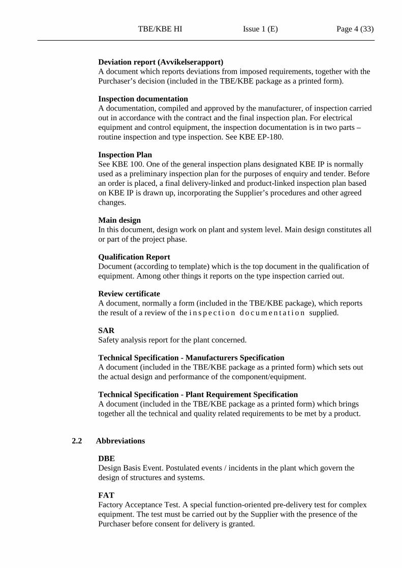
Deviation report (Avvikelserapport) A document which reports deviations from imposed requirements, together with the Purchaser’s decision (included in the TBE/KBE package as a printed form).
Inspection documentation A documentation, compiled and approved by the manufacturer, of inspection carried out in accordance with the contract and the final inspection plan. For electrical equipment and control equipment, the inspection documentation is in two parts – routine inspection and type inspection. See KBE EP-180.
Inspection Plan See KBE 100. One of the general inspection plans designated KBE IP is normally used as a preliminary inspection plan for the purposes of enquiry and tender. Before an order is placed, a final delivery-linked and product-linked inspection plan based on KBE IP is drawn up, incorporating the Supplier’s procedures and other agreed changes.
Main design In this document, design work on plant and system level. Main design constitutes all or part of the project phase.
Qualification Report Document (according to template) which is the top document in the qualification of equipment. Among other things it reports on the type inspection carried out.
Review certificate A document, normally a form (included in the TBE/KBE package), which reports the result of a review of the i n s p e c t i o n d o c u m e n t a t i o n supplied.
SAR Safety analysis report for the plant concerned.
Technical Specification - Manufacturers Specification A document (included in the TBE/KBE package as a printed form) which sets out the actual design and performance of the component/equipment.
Technical Specification - Plant Requirement Specification A document (included in the TBE/KBE package as a printed form) which brings together all the technical and quality related requirements to be met by a product.
2.2 Abbreviations
DBE Design Basis Event. Postulated events / incidents in the plant which govern the design of structures and systems.
FAT Factory Acceptance Test. A special function-oriented pre-delivery test for complex equipment. The test must be carried out by the Supplier with the presence of the Purchaser before consent for delivery is granted.
TBE/KBE HI Issue 1 (E) Page 5 (33)
FSE Functions, systems and equipment.
IP Inspection Plan.
KBE (Kontrollbestämmelser för elektrisk utrustning) Inspection requirements for electrical equipment. General requirements for the inspection procedure. See TBE/KBE document list.
LOCA Loss of coolant accident. A DBE that involves major environmental stresses on equipment located in the reactor containment.
PIE Postulated initial event.
SAT Site Acceptance Test. A special function-oriented test at the Purchaser’s site before complex equipment is handed over. Normally done with the equipment connected and operating as far as possible. Compare FAT.
SSE Safe Shutdown Earthquake. An earthquake of specified strength, after which it must be possible to bring the reactor to a safe state.
TBE (Tekniska bestämmelser för elektrisk utrustning) Technical requirements for electrical equipment. General requirements for environmental compatibility and functionality. See TBE/KBE document list.
TBE/KBE HI Issue 1 (E) Page 6 (33)
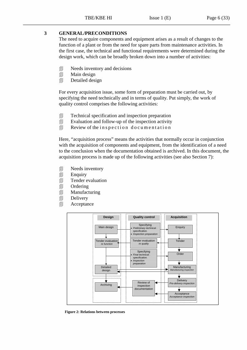
3 GENERAL/PRECONDITIONS The need to acquire components and equipment arises as a result of changes to the function of a plant or from the need for spare parts from maintenance activities. In the first case, the technical and functional requirements were determined during the design work, which can be broadly broken down into a number of activities: Needs inventory and decisions Main design Detailed design For every acquisition issue, some form of preparation must be carried out, by specifying the need technically and in terms of quality. Put simply, the work of quality control comprises the following activities: Technical specification and inspection preparation Evaluation and follow-up of the inspection activity Review of the i n s p e c t i o n d o c u m e n t a t i o n Here, “acquisition process” means the activities that normally occur in conjunction with the acquisition of components and equipment, from the identification of a need to the conclusion when the documentation obtained is archived. In this document, the acquisition process is made up of the following activities (see also Section 7): Needs inventory Enquiry Tender evaluation Ordering Manufacturing Delivery Acceptance
Figure 2: Relations between processes
Main design Enquiry
Tender evaluation re function
Tender
Detailed design
Order
Design Quality control Acquisition
Delivery Pre-delivery inspection
Acceptance Acceptance inspection
Manufacturing Manufacturing inspection
Archiving Review of inspection
documentation
Specifying • Preliminary technical .
specification. • Inspection preparation
Tender evaluation re quality
Specifying • Final technical .
specification. • Inspection
preparation
TBE/KBE HI Issue 1 (E) Page 7 (33)
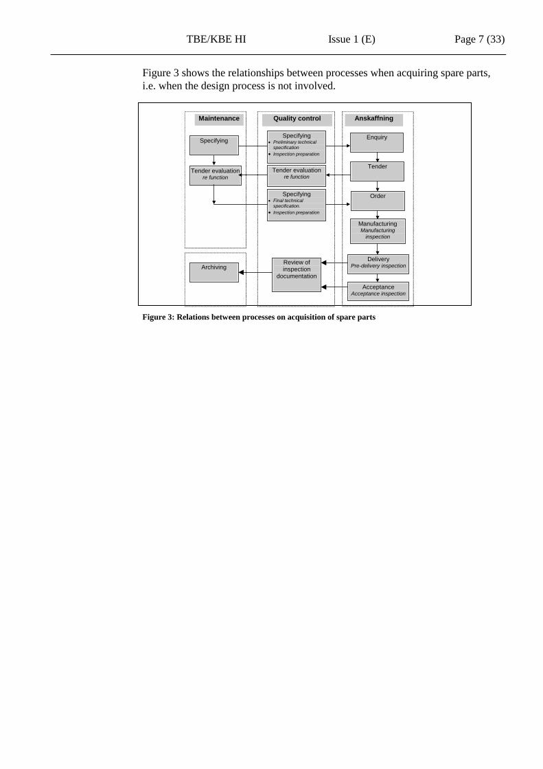
Figure 3 shows the relationships between processes when acquiring spare parts, i.e. when the design process is not involved.
Figure 3: Relations between processes on acquisition of spare parts
Specifying Enquiry
Tender evaluation re function
Tender
Order
Maintenance Quality control Anskaffning
Delivery Pre-delivery inspection
Acceptance Acceptance inspection
Manufacturing Manufacturing
inspection
Archiving Review of inspection
documentation
Specifying • Preliminary technical
specification • Inspection preparation
Tender evaluation re function
Specifying • Final technical
specification. • Inspection preparation

TBE/KBE HI Issue 1 (E) Page 8 (33)
4 REQUIREMENTS The TBE/KBE documents constitute the collected requirements package of the Swedish nuclear power owners regarding the acquisition of components and equipment. In addition to conventional requirements, the package includes requirements that govern nuclear engineering activity. Design, manufacture and inspection of components and equipment must comply with current legislation and regulations and with associated standards. Laws and regulations are mandatory and must be complied with. Certain standards must be complied with to meet official requirements in the regulations. Other standards are applied voluntarily as an aid to specifying. See Figure 4 below.
Figure 4: Requirement hierarchy
Regulations e.g. SSMFS
Standards e.g. IEC, IEEE, SS etc
Swedish laws
Plant requirements
Nuclear-power-specific requirements
Regulations e.g. ELSÄK-FS Standards
e.g. IEC, IEEE, SS etc
Conventional requirements
Sector requirements e.g. EL-AMA
Swedish laws
TBE/KBE HI Issue 1 (E) Page 9 (33)
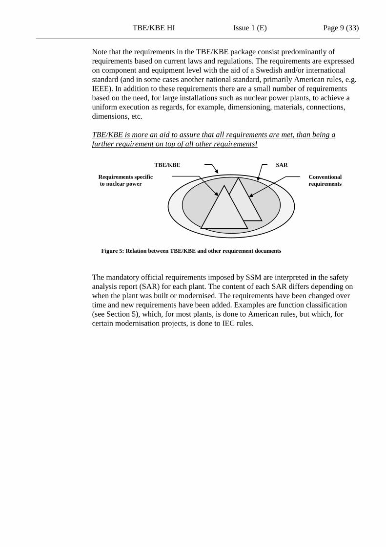
Note that the requirements in the TBE/KBE package consist predominantly of requirements based on current laws and regulations. The requirements are expressed on component and equipment level with the aid of a Swedish and/or international standard (and in some cases another national standard, primarily American rules, e.g. IEEE). In addition to these requirements there are a small number of requirements based on the need, for large installations such as nuclear power plants, to achieve a uniform execution as regards, for example, dimensioning, materials, connections, dimensions, etc. TBE/KBE is more an aid to assure that all requirements are met, than being a further requirement on top of all other requirements!
Figure 5: Relation between TBE/KBE and other requirement documents The mandatory official requirements imposed by SSM are interpreted in the safety analysis report (SAR) for each plant. The content of each SAR differs depending on when the plant was built or modernised. The requirements have been changed over time and new requirements have been added. Examples are function classification (see Section 5), which, for most plants, is done to American rules, but which, for certain modernisation projects, is done to IEC rules.
Requirements specific to nuclear power
Conventional requirements
TBE/KBE SAR

TBE/KBE HI Issue 1 (E) Page 10 (33)
5 FUNCTION CLASSIFICATION The functions of a nuclear power plants are divided into safety classes depending on their importance for safety. Electrical function classification can be done according to American rules and IEEE or according to IAEA and IEC standards. This description is general. A detailed description of how to carry out classification is given in the relevant safety analysis report (SAR).
5.1 Function classification according to IEEE and Swedish practice
Electrical function class 1E Functions in function class 1E - Electrical safety functions - may give an increase in radioactive emissions from the plant in the event of a malfunction after disturbances or incidents.
Electrical function class 2E Functions that belong to functional class 2E - Operational functions - cannot cause an increase in radioactive emissions to the environment in the event of a fault, but are important for the trouble free operation of the plant.
Electrical function class 3E Functions in function class 3E - Service functions - have no effect on reactor safety or production availability.
5.2 Function classification according to IEC 61226
Class A Class A includes the functions, systems and equipment (FSE), which play an important part in maintaining nuclear safety. FSEs according to Class A prevent postulated initial events (PIE) that lead to significant sequences, or that mitigate the consequences of PIE. Class A also includes FSE whose malfunction may lead directly to a significant sequence.
Class B Class B includes the FSE that supplements Class A FSEs in maintaining nuclear safety. The implementation of a Class B FSE may make a Class A FSE unnecessary. Class B also includes FSEs whose malfunction may generate or worsen a PIE.
Class C Class C includes the FSE that plays an alternative or indirect part in maintaining nuclear safety. Class C includes FSE that are important for safety but do not belong to Class A or B. They may form part of the plant’s total response to a transient (or failure) but do not contribute directly to mitigation of the consequences.
Class O Unclassified FSE have no importance for safety and are therefore not subject to any particular nuclear requirements.

TBE/KBE HI Issue 1 (E) Page 11 (33)
6 DOCUMENT DESCRIPTION
6.1 The document package The TBE/KBE package to which this user guide belongs consists of a TBE part containing technical requirements and a KBE part containing verification requirements. TBE 100 General Technical Requirements and explanations TBE 101 Environmental Specification for Normal Operation TBE 102 Environmental specification for Accident Conditions TBE 103 – 122 Product-linked requirements TS Product-linked forms for technical specifications KBE 100 General Quality and Inspection Requirements KBE IP 103 – 122 Product-linked inspection plans KBE EP 101 – 194 Inspection procedures to which KBE IP refers Forms for deviation reporting
Figure 6: The TBE/KBE documents
6.2 Enquiry documentation After an initial inspection preparation, technical documentation (TU) for the enquiry consists of: TS Preliminary product-linked Technical Specification 1 TBE 100 General Technical Requirements and explanations TBE 101-102 Environmental specification according to TS TBE 103-122 Technical Provisions according to TS KBE 100 General Quality and Inspection Requirements KBE IP General product-linked inspection plan according to TS KBE EP 101-194 Inspection procedures according to KBE IP
1 1) Printed TS form (with unique identity) possibly with an attachment in the form of a technical report with description of requirements or, 2) Separate technical requirement specification with unique identity. See also Section 7.2.
KBE KBE TBE 102
TBE TBE 101
TBE TBE 100
TBE TBE
TBE TBE
TBE KBE
TBE 103-122
KBE 100 KBE IP
KBE EP
TBE/KBE HI
User manual
TS forms
Deviation report

TBE/KBE HI Issue 1 (E) Page 12 (33)
6.3 Procurement documentation After assessment of the tender documentation and renewed inspection preparation according to Section 7.5, the procurement documentation consists of the following documents: TS Final product-linked Technical Specification 1 TBE 100 General Technical Requirements and explanations TBE 101-102 Environmental specification according to TS TBE 103-122 Technical Provisions according to TS KBE 100 General Quality and Inspection Requirements Final product-linked
inspection plan stated in TS above (with unique identity) Inspection procedures KBE EP and/or the Supplier’s inspection procedures to
which KBE IP refers.
Figure 7: Procurement documentation
When procurement is complete, TS is used as a basis for plant documentation of both component type and individual components (C-doc.). The final inspection plan with resulting inspection report from the Supplier is used for the i n s p e c t i o n d o c u m e n t a t i o n of the plant (K-doc.).
1 1) Printed TS form (with unique identity) possibly with an attachment in the form of a technical report with description of requirements or, 2) Separate technical requirement specification with unique identity. See also Section 7.4.
Manufacturer’s plan
KBE-EP KBE IP
TBE 100 TBE 101 TBE 102 TBE 10n TBE 11m
Tech. spec.
Tech. report (if any)

TBE/KBE HI Issue 1 (E) Page 13 (33)
7 WORK DESCRIPTION The acquisition process is described very briefly in Section 3. A more detailed description is given here. The expression “acquisition process” is used to mean all necessary activities for acquiring a component or equipment, from the identification of a need and the defining of overall requirements to approval of its delivery, including i n s p e c t i o n d o c u m e n t a t i o n . For repetitive re-acquisition of electrical components of standard nature it is practical to simplify acquisition by means of a type approval within the framework of the installation in question or the current routines for the unit. The purpose of type approval must be to qualify the component for the broadest possible use in the plant, i.e. preferably without restrictions on function class or siting. It is important to use as far as possible the documentation that was produced in previous stages of the process. Do not re-write the documents for every stage in the process. Add new information to existing documents as the work progresses.
7.1 Main design
Changes to a plant and associated acquisition requirements are managed and documented in accordance with the Purchaser’s instructions and routines. M a i n d e s i g n is done on the basis of the requirements laid down at the time of the change decision. In this phase preconditions for specification of components and equipment are produced (among other things), to be used in acquisition (or later on acquisition at the time of detailed design). Examples of such preconditions are: system/equipment number type of equipment function dimensioning electrical function class environmental requirements
Main design
Design Quality control Acquisition
Specifying • Preliminary technical .
specification. • Inspection preparation

TBE/KBE HI Issue 1 (E) Page 14 (33)
7.2 Specifying, including preliminary scope of inspection
See also Section 8, which gives detailed instructions for filling in a TS (Sections 8.1-8-2) and inspection plan (Section 8.3). Specifying is done on a printed TS form. Alternatively a separate technical specification may be used, based on needs and prerequisites. The TS is the top document for the component/equipment. On the TS form the Purchaser specifies the details in the header of the form, as well as the function requirements. Often it is necessary to refer to a separate specification of requirements which was produced in the main design stage. Where the choice is made to produce separate technical specification it is important that the same details are dealt with as in the printed form. When specifying, consideration must be given to the requirements and preconditions from the mechanical design, e.g. the mechanical connection of sensors (thread size etc). These requirements are normally specified in the TS for mechanical equipment. It is very important that these requirements/specifications are coordinated.
7.3 Enquiry and tender evaluation The technical documentation (tekniska underlaget, TU) for the enquiry (see Section 6.2) is sent to various suppliers so that they can submit tenders. Tenders received must therefore be evaluated.
This involves technical, quality-related and financial evaluation of the tenders. In conjunction with enquiry and evaluation, an assessment of the Supplier shall be carried out. The Supplier is assessed in terms of, among other things, quality system, previous experience, product quality, stability and ability to supply in the future.
Main design
Design Quality Control Acquisition
Enquiry Specifying
• Preliminary technical specification
• Inspection preparation
Design Quality control Acquisition
Enquiry Specifying
• Preliminary technical specification
• Inspection preparation
Tender
Tender evaluation re function
Tender evaluation re function
TBE/KBE HI Issue 1 (E) Page 15 (33)
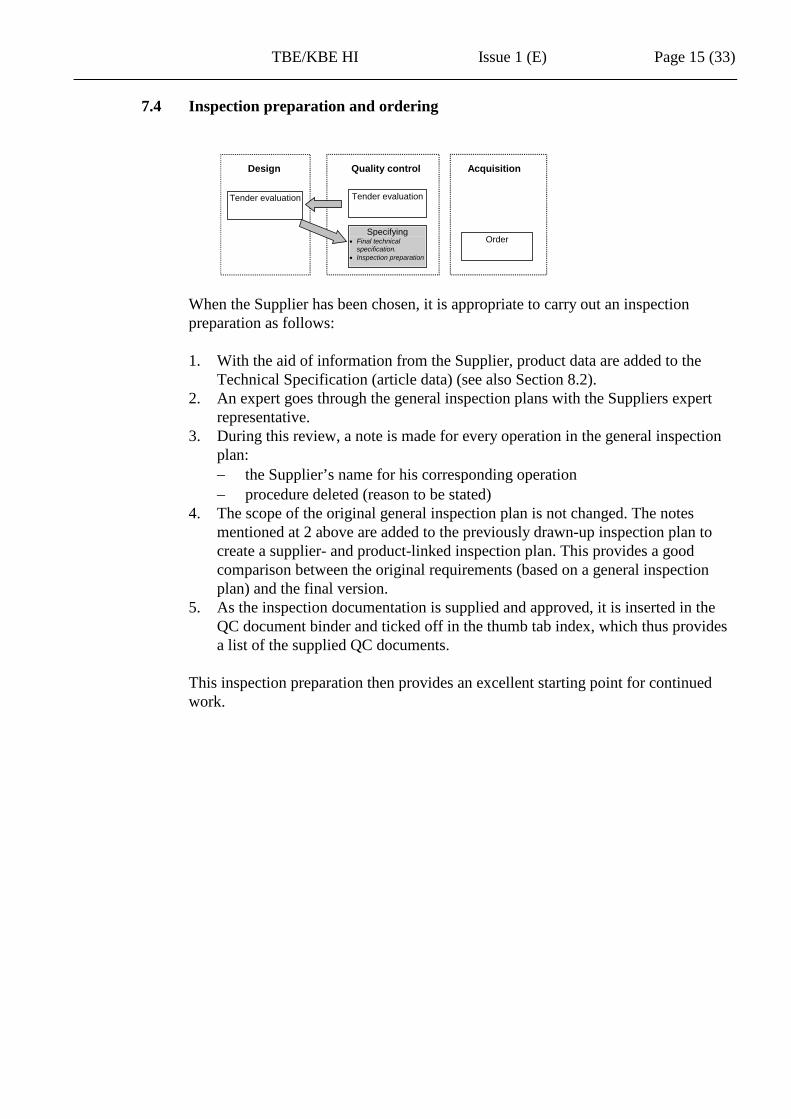
7.4 Inspection preparation and ordering
When the Supplier has been chosen, it is appropriate to carry out an inspection preparation as follows: 1. With the aid of information from the Supplier, product data are added to the
Technical Specification (article data) (see also Section 8.2). 2. An expert goes through the general inspection plans with the Suppliers expert
representative. 3. During this review, a note is made for every operation in the general inspection
plan: − the Supplier’s name for his corresponding operation − procedure deleted (reason to be stated)
4. The scope of the original general inspection plan is not changed. The notes mentioned at 2 above are added to the previously drawn-up inspection plan to create a supplier- and product-linked inspection plan. This provides a good comparison between the original requirements (based on a general inspection plan) and the final version.
5. As the inspection documentation is supplied and approved, it is inserted in the QC document binder and ticked off in the thumb tab index, which thus provides a list of the supplied QC documents.
This inspection preparation then provides an excellent starting point for continued work.
Tender evaluation
Order
Design Quality control Acquisition
Tender evaluation
Specifying • Final technical
specification. • Inspection preparation
TBE/KBE HI Issue 1 (E) Page 16 (33)
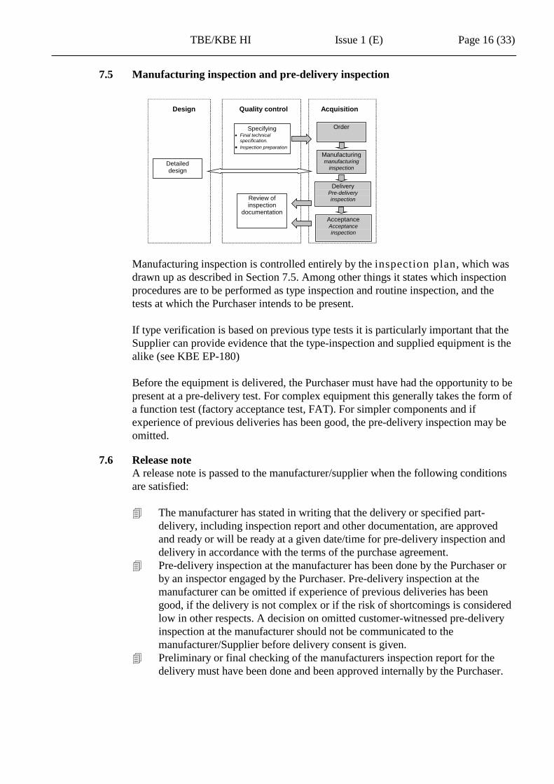
7.5 Manufacturing inspection and pre-delivery inspection
Manufacturing inspection is controlled entirely by the inspection plan, which was drawn up as described in Section 7.5. Among other things it states which inspection procedures are to be performed as type inspection and routine inspection, and the tests at which the Purchaser intends to be present. If type verification is based on previous type tests it is particularly important that the Supplier can provide evidence that the type-inspection and supplied equipment is the alike (see KBE EP-180) Before the equipment is delivered, the Purchaser must have had the opportunity to be present at a pre-delivery test. For complex equipment this generally takes the form of a function test (factory acceptance test, FAT). For simpler components and if experience of previous deliveries has been good, the pre-delivery inspection may be omitted.
7.6 Release note A release note is passed to the manufacturer/supplier when the following conditions are satisfied: The manufacturer has stated in writing that the delivery or specified part-
delivery, including inspection report and other documentation, are approved and ready or will be ready at a given date/time for pre-delivery inspection and delivery in accordance with the terms of the purchase agreement.
Pre-delivery inspection at the manufacturer has been done by the Purchaser or by an inspector engaged by the Purchaser. Pre-delivery inspection at the manufacturer can be omitted if experience of previous deliveries has been good, if the delivery is not complex or if the risk of shortcomings is considered low in other respects. A decision on omitted customer-witnessed pre-delivery inspection at the manufacturer should not be communicated to the manufacturer/Supplier before delivery consent is given.
Preliminary or final checking of the manufacturers inspection report for the delivery must have been done and been approved internally by the Purchaser.
Detailed design
Order
Design Quality control Acquisition
Manufacturing manufacturing
inspection
Specifying • Final technical
specification. • Inspection preparation
Delivery Pre-delivery inspection
Acceptance Acceptance inspection
Review of inspection
documentation

TBE/KBE HI Issue 1 (E) Page 17 (33)
7.7 Receiving inspection When the arrival inspection against the order (correct goods and quantity) has been done, receiving inspection can be done. The scope of the receiving inspection varies depending on the type of component and may, for instance cover visual inspection, insulation inspection, calibration, function check and the like. The scope is governed by instructions at the particular plant.
7.8 Review of the inspection documentation
The purpose of this review is to check that the Supplier provides the agreed i n s p e c t i o n d o c u m e n t a t i o n , and that the documentation verifies that the agreed tests have been done. The review will be very much easier a good inspection preparation has been done, in accordance with Section 7.5.
7.9 Documentation On the basis of the i n s p e c t i o n d o c u m e n t a t i o n supplied, the Purchaser can write a q u a l i f i c a t i o n r e p o r t , a r e v i e w c e r t i f i c a t e and, where applicable, a d e v i a t i o n r e p o r t . These documents, together with the Suppliers documentation are then included in the final documentation.
Detailed design
Design Quality control Acquisition
Manufacturing manufacturing
inspection
Delivery Pre-delivery inspection
Acceptance Acceptance inspection
Review of inspection
documentation
Archiving

TBE/KBE HI Issue 1 (E) Page 18 (33)
8 DETAILED COMPLETION INSTRUCTIONS This section describes in detail how to fill in: Section 8.1: TS form “Plant Requirement Specification” Section 8.2: TS form “Manufacturer’s Specification” Section 8.3: form for scope of inspection: “Inspection plan”
8.1 TS form “Plant Requirement Specification” This document is filled in by the Purchaser and constitutes the Purchaser’s requirements to be fulfilled by the Supplier. The TS form for “Electrical Equipment” and “Field Mounted Component” are used below as examples. Section 8.1.1: Form header (the same for all TSs) Section 8.1.2: Requirement Specification Section 8.1.3: Process Data (the same for all TSs) Section 8.1.4: Service Conditions (the same for all TSs) Section 8.1.5: General Technical and Quality Requirements (the same for all
TSs) Section 8.1.6: General Technical and Quality Requirements – Mechanical parts Section 8.1.7: Surface treatment, Painting system (the same for all TSs) In some cases it may be appropriate to refer to a separate requirement specification. Write the requirement specification so that it can be used with more than one supplier. Requirements not stated in the applicable TBE must be stated. On the other hand, it is not appropriate to state here requirements that are included generally in the TBE. It is important that the administrator should be thoroughly familiar with the requirements imposed in TBE 100, KBE 100 and in the product-specific TBEs that apply to the equipment.
TBE/KBE HI Issue 1 (E) Page 19 (33)
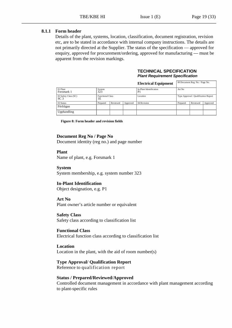
8.1.1 Form header Details of the plant, systems, location, classification, document registration, revision etc, are to be stated in accordance with internal company instructions. The details are not primarily directed at the Supplier. The status of the specification — approved for enquiry, approved for procurement/ordering, approved for manufacturing — must be apparent from the revision markings.
Figure 8: Form header and revision fields
Document Reg No / Page No Document identity (reg no.) and page number
Plant Name of plant, e.g. Forsmark 1
System System membership, e.g. system number 323
In-Plant Identification Object designation, e.g. P1
Art No Plant owner’s article number or equivalent
Safety Class Safety class according to classification list
Functional Class Electrical function class according to classification list
Location Location in the plant, with the aid of room number(s)
Type Approval/ Qualification Report Reference to qualification report
Status / Prepared/Reviewed/Approved Controlled document management in accordance with plant management according to plant-specific rules
TECHNICAL SPECIFICATIONPlant Requirement Specification
Electrical Equipment 00 Document Reg. No. / Page No.
01 PlantForsmark 1
System323
In-Plant IdentificationP1
Art No
02 Safety Class (SC)SC 3
Functional Class1E
Location Type Approval / Qualification Report
03 Status Prepared Reviewed Approved 04 Revision Prepared Reviewed ApprovedFörfrågan
Upphandling
TBE/KBE HI Issue 1 (E) Page 20 (33)
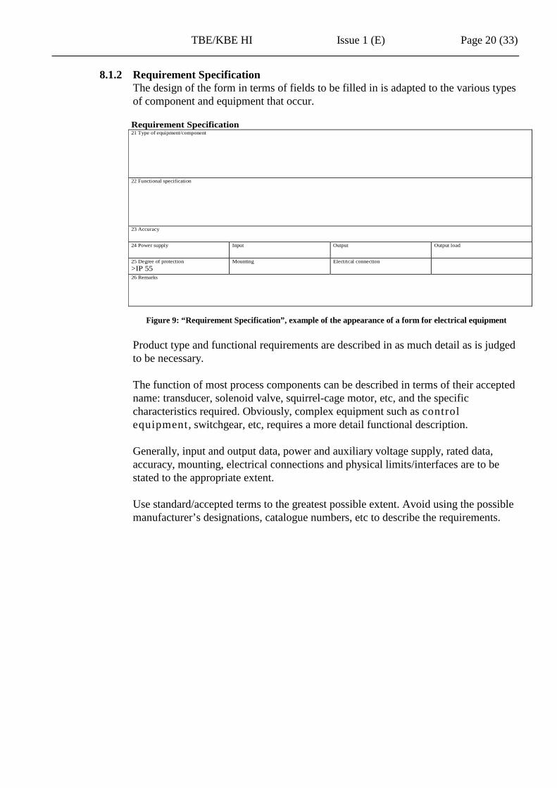
8.1.2 Requirement Specification The design of the form in terms of fields to be filled in is adapted to the various types of component and equipment that occur.
Figure 9: “Requirement Specification”, example of the appearance of a form for electrical equipment Product type and functional requirements are described in as much detail as is judged to be necessary. The function of most process components can be described in terms of their accepted name: transducer, solenoid valve, squirrel-cage motor, etc, and the specific characteristics required. Obviously, complex equipment such as control equipment, switchgear, etc, requires a more detail functional description. Generally, input and output data, power and auxiliary voltage supply, rated data, accuracy, mounting, electrical connections and physical limits/interfaces are to be stated to the appropriate extent. Use standard/accepted terms to the greatest possible extent. Avoid using the possible manufacturer’s designations, catalogue numbers, etc to describe the requirements.
Requirement Specification21 Type of equipment/component
22 Functional specification
23 Accuracy
24 Power supply Input Output Output load
25 Degree of protection>IP 55
Mounting Electrical connection
26 Remarks

TBE/KBE HI Issue 1 (E) Page 21 (33)
Power and auxiliary voltage If the equipment is to receive power or auxiliary voltage from networks in the plant with a rated voltage of 220 V or 380 V, these values must be stated, not 230 V or 400 V respectively.
Degree of protection In the process areas, the lowest permitted degree of protection is IP54 to IEC 60529. For components that may be exposed to sprinkling or hosing in connection with decontamination, IP55 must be specified. For components located in reactor containment, IP55 is generally applicable. However, according to the assembly instructions, certain enclosures in addition to these must be provided with drain holes at the low point to prevent condensation collecting in normal service owing to humidity cycling. For components to be placed in enclosures (equipment cabinets and boxes), IP20 must be specified.

TBE/KBE HI Issue 1 (E) Page 22 (33)
8.1.3 Process Data The process data needed to be able to specify the component/equipment must be stated.
Figure 10: “Process data”. Example of a form for a Field Mounted Component
Process Connection Type of connection to the process, e.g. thread, weld, flange
Dimension E.g. thread size
Material E.g. stainless steel, grade 2333
Medium Medium in contact with the component, e.g. reactor water, air
Design Pressure Design pressure (state unit)
Design Temperature Design temperature in degrees Celsius
Operating Pressure Operating pressure (state unit)
Operating Temperature Operating temperature in degrees Celsius
Transients E.g. pressure surges (magnitude/duration)
Process Data41 Process connection Dimension Material Medium
42 Design Pressure (abs) Design Temperature Operating Pressure (abs) Operating Temperature
43 Transients
44 Remarks

TBE/KBE HI Issue 1 (E) Page 23 (33)
8.1.4 Service Conditions Components and equipment must continue to function under the actual environmental conditions to which they are subjected in normal operation and in extreme/accident operation of the plant. For equipment that is subjected to raise environmental stresses due to internal temperature rise, process impact, other local factors or extreme/accident operation of the plant, the actual expected values must be stated. For example, pressure and temperature transients in the process, loss of power supply, loss of ventilation, etc. For safety-classified equipment and equipment that is important for safety it is important that such deviations are identified and analysed.
Figure 11: “Service Conditions” It is important that the user of TBE/KBE knows which environmental factors are specified in the three basic severity levels in TBE 101 so that any additional stresses can be can be specified here. The additional requirements not covered by TBE 100 – 102 are specified under “Service Conditions”; see also Section 8.1.4.2.
Service Conditions51
Normal operation52
Extreme operation53
Accident ConditionsEnligt TBE 101 Stränghet C Funktionskrav enligt nedanAdditional Additional Accident Transients
Amb Temp. (long term) C: Amb Temp. (short term) C: Seismic SSE SL3Amb Temp. (short term) C: Seismic Category 1AHumidity, % RH:Vibration, m/s2, Hz LOCA BWR/PWR genericRadiation, kGy/year: Time: days
Radiation dose: kGy54 Remarks

TBE/KBE HI Issue 1 (E) Page 24 (33)
8.1.4.1 Normal Operation NOTE: This section also gives instructions for filling in Section 8.1.5 “General Technical and Quality Requirements”. “Normal operation” is the state of the plant in power production, routine shutdowns, startup, etc, without faults in cooling functions and within the design values for outdoor temperature and cooling water. The conditions that prevail during the operation of systems that include the component or equipment are controlling, even if the system is not normally in operation. For the majority of components and for most equipment, the standardised environment descriptions (severity levels) stated in TBE 101 can be used without special additions. Note that TBE 101 does not describe requirements to be met by e.g. equipment installed under water, nor the specific environmental requirements that apply in computer rooms. The basic severity levels A, B, C and D describes generally the environment that is expected to exist in the stated areas including certain margins. Severity levels A and B excluding the environmental factor ionising radiation agree to a large extent with the practice that prevails in the process industry. TBE 101 – Severity A Control rooms, electrical rooms, corridors,
passageways, etc. Process rooms outside the reactor containment without hot or active process systems
TBE 101 – Severity B Process rooms outside the reactor containment with hot and/or active process systems
TBE 101 – Severity C The reactor containment TBE 101 – Severity D Non weatherprotected locations
Figure 12: Examples of severity in different types of room: Severity A shall not be used for areas where ionising radiation occurs. Severity B is appropriate in “red” areas if expected radiation doses are low.

TBE/KBE HI Issue 1 (E) Page 25 (33)
8.1.4.2 Additional requirements
Figure 13: Known actual values for temperature, radiation, mechanical stresses, transients etc are to be stated each on a separate line under “Additional” or “Accident Conditions”. The dose rate must always be stated for severity levels B and C. The dose rate must be based on known actual values in the area or based on decisions about requirement level.
Ambient temperature The basic severity levels in TBE 101 dealt with in the previous section cover continuous ambient temperatures up to 40 °C in A-areas and up to 55 °C in B- and C-areas. 1 Additional requirements according to severity B (55 °C) or a higher value with regard to heat are to be specified for equipment that is subjected to a higher ambient temperature due to internal heating, the impact of nearby process parts or by other local causes. If the temperature rise is short-term, the expected time and frequency are to be stated. Generally, an additional requirement of least 70 °C must be specified for components intended to be installed close to hot process parts. Components located inside enclosures (equipment cabinets and boxes) must be assumed to have an ambient temperature 15 degrees C above the temperature that applies to the enclosure unless other values are known (based on population rules, for example). Ambient temperature plus 15 degrees therefore determines which severity is to be specified.
Humidity Additional requirement severity C concerning humidity is to be specified if the humidity in A-areas significantly exceeds 50% RH.
1 From the point of view of aging, it is assumed that the mean temperature around safety-classified equipment in A-areas is of the order of 20 °C and that the highest internal temperature ("hot spot") is 35 °C.
Service Conditions51
Normal operation52
Extreme operation53
Accident ConditionsEnligt TBE 101 Stränghet C Funktionskrav enligt nedanAdditional Additional Accident Transients
Amb Temp. (long term) C: Amb Temp. (short term) C: Seismic SSE SL3Amb Temp. (short term) C: Seismic Category 1AHumidity, % RH:Vibration, m/s2, Hz LOCA BWR/PWR genericRadiation, kGy/year: Time: days
Radiation dose: kGy54 Remarks

TBE/KBE HI Issue 1 (E) Page 26 (33)
EMC Immunity and emission requirements according to TBE 101, Tables 5 is generally applicable. For equipment containing electronics located in areas with a higher interference level (e.g. some switchgear) additional requirements are specified as regards immunity to interference.
Ionising radiation It is a general rule that one should avoid locating electrical equipment in "hot/red" areas. Components that must be located close to a process (e.g. valve actuators, transducers, etc, including associated wiring) must be located as far as technically possible from the parts of the process that cause the radiation (and also heat). The total radiation loading for a single component or piece of equipment is calculated from actual operating dose rates and design life. If the total radiation dose does not exceed the order of 1 kGy, no special measures are required as regards the environmental factor ionising radiation. The dose is not specified in TS and verification is not needed in the environmental qualification. However, exceptions apply for components with modern electronics and for fibre-optic cables. If the total radiation dose is higher than of the order of 1 kGy, the environmental factor ionising radiation must be considered for components and equipment that contains polymer materials essential for correct operation. The radiation dose is stated in TS and verification of the radiation resistance must be included in the environmental qualification of the component type. The majority of temperature-resistant instrumentation components intended for installation in or adjacent to hot process parts can withstand doses up to 100 kGy (10E7 Rad) without major problems. However, as stated earlier, this does not apply for electronics and fibre-optic cable. For electronics, the maximum radiation dose is 10 Gy. If the total radiation dose exceeds 100 kGy, special measures should be taken, since the performance of polymer and other materials subject to aging may be reduced. The design life can be maintained by planned replacement of parts subject to aging. If the total radiation dose exceeds the order of magnitude of 10 MGy during the time for which the component is installed, the use of materials other than metallic and ceramic materials is excluded if the properties of the material are significant for safe operation or environmental protection. The operating dose rate is stated in the TS in kGy/service year or mGy/h according to station-linked preconditions. Primarily, the dose rates must be based on actual measurement data from the plant. In the individual case, an assessment of the dose loading in normal service and at DBE must be made.

TBE/KBE HI Issue 1 (E) Page 27 (33)
Obtain readings from radiation protection in every doubtful case. Do not accept “don’t know” answers. The DBE dose is added to the operating dose in accordance with any requirements in the relevant FSAR if operation of the component is required from the point of view of reactor safety in the DBE case. Verification of the immunity to ionising radiation for components located in the primary space of the reactor containment or in active process areas should generally be done in accordance with KBE EP-151, Severity C, 50 kGy, unless other more precise figures have been produced.
8.1.4.3 Extreme Operation
Figure 14: State any extreme external conditions that may apply in normal and abnormal system operation - but not DBE - and which are not covered by the basic severity levels in TBE 101. Note that requirements for function in extreme operation with 90 °C, 8 h, per year, are included in TBE 101, Severity C.
8.1.4.4 Accident Conditions
Figure 15:
Service conditions 51 Normal operation
52 Extreme operation
53 Accident conditions
According to TBE 101 Strictness C Functional requirements as below Additional Additional Accident Transients Ambient temp. (long-term) C: Ambient temp. (short-term) C: Seismic SSE SL3 Ambient temp. (short-term) C: Seismic Category 1A
Humidity, % RH: Vibration, m/s 2 , Hz LOCA BWR/PWR generic Radiation, kGy/year: Time: days
Radiation dose: kGy 54 Remarks
Service conditions 51 Normal operation
52 Extreme operation
53 Accident conditions
According to TBE 101 Strictness C Functional requirements as below Additional Additional Accident transients Ambient temp. (long-term) C: Ambient temp. (short-term) C: Seismic SSE SL3 Amb Temp. (short-term) C: Seismic Category 1A
Humidity, % RH: Vibration, m/s 2 , Hz LOCA BWR/PWR generic Radiation, kGy/year: Time: days
Radiation dose: kGy 54 Remarks

TBE/KBE HI Issue 1 (E) Page 28 (33)
DBE Conditions State in accordance with plant-specific preconditions the DBEs at which the equipment must operate. Normally this applies only to safety-classified equipment and equipment of importance for safety.
LOCA Additional requirements in accordance with TBE 102:1 Table 1. Any requirements for function at LOCA are to be stated, including the time requirement. Complete and undisturbed functioning in accordance with specification in conjunction with a pipe breakage environment is not possible for electrical components. The function that must be satisfied in conjunction with LOCA must therefore be separately specified in the function requirements. For example, one may specify measurement with greater permitted inaccuracy than normal, active function in both or only one direction, lowest insulation level, a particular fault function that is not permitted to occur, etc. These are important details for a correct accident test program and qualification at reasonable cost. Where equipment that is already qualified is purchased, this also makes it easier to evaluate the qualification level against the current application.
Earthquake – SSE Additional requirements in accordance with TBE 102:2. Requirements for function in the event of an earthquake are to be stated, including requirement level and seismic category, which defines the function requirements during and/or after an earthquake, or only passive requirements. Note that TBE 102:2 and KBE EP-147 are not sufficient as a basis for imposing seismic requirements / verification. The following are added: Actual floor response spectrum which is compared with seismic environmental
classes Reinforcing factors in cabinets Damning for relevant equipment The function to be fulfilled during and/or after the earthquake must be separately specified in the function requirements above. It must, for example, be clear whether malfunction can be accepted during but not after the earthquake (e.g. electromechanical components with moving parts). Compare the reasoning about function requirements at LOCA above.
External pipe breakage Additional requirements in accordance with TBE 102:1 Table 1. Any requirements for function on external pipe breakage are to be stated, including the time requirement. Requirements for mechanical resistance to missiles and jets are to be stated.

TBE/KBE HI Issue 1 (E) Page 29 (33)
Severe accidents The environment in the event of severe accidents is not described in TBE 102 and function requirements cannot be specified with the methods used in the sections above. Environment and function requirements must, if necessary, be specified in accordance with plant-specific preconditions. Severe accidents may include sequences of events with sever core damage “filter scenario” or a “beyond design” earthquake.
8.1.5 General technical and quality requirements This section specifies technical and quality-governing provisions, supplementary requirements with regard to environmental compatibility, and the scope of inspection/inspection plan.
Figure 16:
Technical and quality requirements TBE 100, KBE 100 (pre-printed on the form). Product-specific TBE from the series TBE 103 – 122 is to be stated. Certain equipment requires more than one TBE to be stated.
Environmental specifications TBE 101, Severity A, B, C or D. Accident curve, e.g. TBE 102:1 BWR 2
Additional requirements Seismic requirements, e.g. TBE 102:2 SL 4
Safety class Safety class
Functional class Electrical functional class (see Section 5)
General inspection plan General inspection plan from series KBE IP 103-122
Final inspection plan Delivery-linked inspection plan specified at procurement
General Technical and Quality Requirements71 Technical and Quality RequirementsTBE 100 KBE 100 TBE 10872 Environmental SpecificationsTBE 101, Severity: C TBE 102:1
Additional Environment severitiesHumidity, % RH: Radiation
73 Additional Requirements
74 Safety Class (SC)SC3
Functional Class1E
General Inspection PlanKBE IP
Final Inspection plan
75 Remarks

TBE/KBE HI Issue 1 (E) Page 30 (33)
8.1.6 General technical and quality requirements - mechanical parts
Figure 17: For components that contain pressurised parts in contact with media (e.g. a pocket for a Pt100 sensor, flow sensors, and other “in-line” components) the requirements that apply according to TBM/KBM are to be stated directly. It is permissible to refer, for example, to a separate specification for the mechanical component. Note that currently TBM/KBM does not impose requirements for measuring instrumentation connected via impulse pipes, e.g. pressure transducers with valve block.
8.1.7 Surface treatment, painting systems Any specific requirements for surface treatment and painting due to corrosive environment, for example, or the need for decontamination, must be stated. Normally, the TBE requirements indirectly provide sufficient requirements to be met by the manufacturer, i.e. the manufacturer’s standard methods can be accepted.
Figure 18: Surface treatment, painting systems State, for instance, the Manufacturers standard unless there are particular requirements.
8.2 Manufacturers Specification This form is used to specify data and performance of the equipment/component that has been evaluated against the requirements and is to be procured. The details are obtained from the Supplier and at the end of the procurement process they should have been verified by the Purchaser in accordance with the TBE/KBE requirements. It is a general rule that requirements specified higher up in TS should not be changed when the performance of the chosen equipment deviates from the requirements.
General Technical and Quality Requirements - Mechanical parts81 Technical Specification reference Inspection Plan Safety Class (SC)
82 Quality Class Tightness Class Cleanliness Class Inspection Class
83 Technical and Quality Requirements (TBM/KBM)
84 Remarks
Surface treatment, Painting system91 Surface treatment Painting system

TBE/KBE HI Issue 1 (E) Page 31 (33)
8.3 Inspection Plan
8.3.1 General Inspection plans are used as a tool for specifying the scope of inspection for purchased equipment (or for a defined part of a project) and to structure the inspection report in accordance with the requirements imposed for final approval and plant archiving. The inspection plan and the technical specification are the main documents required for enquiry and procurement and at inspection during and after manufacture.
General inspection plans There are general inspection plans KBE IP for different types of equipment and components. Normally, the same serial number applies for equipment-linked TBE and associated KBE IP, and only one KBE IP should be used as a basis for the scope of inspection. However, KBE IP-104, -105 and -106 deviate from this rule. General inspection plans KBE IP-xxx are normally used when inviting bids for equipment for which no final inspection plan has been produced before or where the inspection plan is obsolete. The manufacturer produces a draft final inspection plan for the component type or for the current delivery, in accordance with instructions in KBE 100, and encloses this, as well as applicable procedures, to the tender.
Final inspection plans After evaluation of the scope of inspection proposed in the tender, a final inspection plant is prepared. A final product-linked or order-linked inspection plan must always be produced before an order is placed. Interaction with the Manufacturer is described in KBE 100. Final inspection plans for electrical equipment are normally drawn up by the Purchaser on the basis of information supplied by the Manufacturer. On re-purchasing, the final inspection plan that was used for the main procurement procedure is used. However, the scope of inspection as regards type inspection must be clarified with the supplier. Normally the type inspection report is replaced with a certificate of identity from the Manufacturer.
TBE/KBE HI Issue 1 (E) Page 32 (33)
8.3.2 Abbreviations In the inspection plans, a number of codes are used to indicate the scope, responsibility, any independent monitoring, and documenting. The codes are explained in the inspection plan, but the following should be known for the operational work.
Type of inspection operation (first letter in the box)
A = Routine (100%) Inspection The operation must be carried out for all supplied units during the manufacturing process or a final inspection before delivery.
S = Sample Inspection The operation must be carried out on a selection from the delivery, using statistical methods. Parameters must be stated in the inspection plan. Normally applied only to components in delivered in large quantities and to sample pieces from cables.
T = Type Inspection This operation must be carried out on at least one component or piece of equipment representative of the delivery. Type verification of conventional requirements for standard components and equipment (environmental compatibility, performance) is normally done by the manufacturer at market launch of the product and in such cases this operation relates only to reporting of the documentation. Note that type-tested examples must not be included in the delivery. Code A, T or S must be stated for all procedures that involve an inspection activity for the delivery in question. The code may be omitted if the operation relates only to documentation or checking (desk activity).
Responsible for documented inspection (second letter) Inspection performed and documented by: E = Manufacturer D = Supplier B = Purchaser This code defined the responsibility for ensuring that the operation is carried out with a satisfactory result and documented. Normally, the responsibility rests with the Manufacturer (E).

TBE/KBE HI Issue 1 (E) Page 33 (33)
Inspection supervision (if any) (third letter) Inspection supervised by: B = Purchaser C = Inspector engaged by Purchaser D = Supplier This code indicates that the operation must be supervised by a body independent of the manufacturer. The person responsible for the inspection operation (normally the manufacturer) must engage this supervision in accordance with rules in KBE 100. The absence of the code (-) means that no independent supervision is required.
Documentation (fourth letter) R = Technical Report P = Inspection Record I = Certificate This code indicates particular requirements that apply to the process of documenting the operation. The absence of the code indicates that there is no need to document the inspection operation. The manufacturer’s internal methods have been judged by the Purchaser to be sufficient to ensure that the operation will be correctly performed. The code stated at Delivery Release Inspection or KBE EP-180 means that a summarising certificate/report on inspection procedures performed must be provided. R Technical Report means a more extensive report with analyses, assessments,
etc. P Inspection Record means the same as Certificate but with the necessary
measured values reported. I Certificate means certification that an inspection has been performed with a
satisfactory result.