Embed Size (px)
Citation preview

Technical Procedure for Firearm Examination North Carolina State Crime Laboratory Firearm and Tool Mark Section
Version 5 Effective Date: 05/10/2013
_____________________________________________________________________________________________________
___________________________________________________________________________________________________
Page 1 of 34
All copies of this document are uncontrolled when printed.
Technical Procedure for Firearm Examination 1.0 Purpose – To outline the procedures for examination of firearm evidence.
2.0 Scope – This procedure applies to cases submitted to the Firearm and Tool Mark Section that contain
firearms.
3.0 Definitions • Action – The working mechanism of a firearm. Examples include automatic, semiautomatic, lever,
bolt, etc. • Active safety – A safety system that requires direct manual manipulation by the user. • Ammunition – One or more loaded cartridges consisting of a primed case, propellant, and with one
or more projectiles. • Autoloading firearm – A firearm that uses the energy of discharge to perform the loading portion of
the operating cycle. • Automatic firearm – A firearm design that feeds cartridges, fires, extracts and ejects cartridge cases
as long as the trigger is fully depressed and there are cartridges in the feed system. • Barrel length – The distance between the end of the barrel and the face of the closed breechblock or
bolt. On revolvers, it is the length of the barrel including the threaded portion within the frame. • Breechblock – The locking and cartridge head support mechanism of a firearm that does not operate
in line with the axis of the bore. • Caliber (Firearm) – The approximate diameter of the circle formed by the tops of the lands of a
rifled barrel. • Cartridge – A single unit of ammunition consisting of the case, primer, and propellant with one or
more projectile(s). Also applies to a shotshell. • Cartridge case – The container for all other components which comprise a cartridge. • Chamber – The rear part of the barrel bore that has been formed to accept a specific cartridge. • Cock – To place a firing mechanism under spring tension. • Compensator – A device attached to or integral with the muzzle end of the barrel to utilize
propelling gases for counter-recoil. • Cylinder – The rotatable part of a revolver that contains the chambers. • Double action – A handgun mechanism in which a single pull of the trigger cocks and releases the
hammer. • Ejection pattern – The charting of locations where a particular firearm ejects fired cartridge cases. • Ejection port – An opening in the receiver and/or slide to allow ejection. • Ejector – A portion of a firearm’s mechanism which ejects or expels cartridges or cartridge cases
from a firearm. • Extractor – A mechanism for withdrawing the cartridge or cartridge case from the chamber. • Firearm – An assembly of a barrel and action from which a projectile(s) is propelled by products of
combustion. • Flare – The circular gray-black deposits around the face of the chambers of a revolver produced by
gunpowder residues upon discharge. • Flash suppressor – A muzzle attachment designed to reduce muzzle flash. • Gauge – The number of round lead balls of bore diameter that equal one pound. Thus 12 gauge is the
diameter of a round lead ball weighing 1/12 pound. • Groove – The lowered portion between the lands in a rifled bore. • Hammer – A component of the firing mechanism which gives impulse to the firing pin or primer.

Technical Procedure for Firearm Examination North Carolina State Crime Laboratory Firearm and Tool Mark Section
Version 5 Effective Date: 05/10/2013
_____________________________________________________________________________________________________
___________________________________________________________________________________________________
Page 2 of 34
All copies of this document are uncontrolled when printed.
• Hammer notch – A groove in a hammer which engages a firing or safety component. • Hand – The lever that rotates a revolver cylinder. • Land – The raised portion between the grooves in a rifled bore. • Lock – The action, either manual or automatic, of locking or supporting the bolt of a firearm
immediately prior to firing. • Magazine – A container for cartridges which has a spring and follower to feed cartridges into the
chamber of a firearm. • Muzzle – The end of a firearm barrel from which the bullet or shot emerges. • Muzzle velocity – The velocity of a projectile as it exits the muzzle of a firearm. • Ogive – The curved forward part of a bullet. • Overall length – The dimension measured parallel to the axis of the bore of a firearm from the
muzzle to a line perpendicular to the axis and tangent to the rearmost point of the butt plate or grip. • Passive safety – A safety system that does not require direct manual manipulation by the user. • Pistol – A handgun in which the chamber is part of the barrel. • Ratchet – A notched wheel on the rear of a revolver cylinder which causes the cylinder to rotate
when force is applied by a lever (hand). • Receiver – The basic unit of a firearm which houses the firing and breech mechanism and to which
the barrel and stock are assembled. • Revolver – A firearm, usually a handgun, with a cylinder having several chambers so arranged as to
rotate around an axis and be discharged successively by the same firing mechanism. • Sear – A component which retains the hammer or striker in the cocked position until the trigger is
pulled. • Semiautomatic firearm – A repeating firearm requiring a separate pull of the trigger for each shot
fired, and which uses the energy of discharge to perform a portion of the operating or firing cycle (usually the loading portion).
• Single action – An action requiring the manual cocking of the hammer before sufficient pressure on the trigger releases the firing mechanism.
• Slide – A component attached to and reciprocating with the breechblock. • Striker – A rod-like firing pin or a separate component which impinges on the firing pin. • Suppressor – A type of silencer which reduces muzzle blast by decreasing the velocity of escaping
gases, but maintains a bullet’s high velocity. • Trigger pull – The amount of force which must be applied to the trigger of a firearm to cause sear
release.
4.0 Equipment, Materials and Reagents • Stereomicroscope • Comparison microscope • Comparison microscope reference bullet • Sper Scientific Digital Sound Meter (located in the Raleigh Laboratory) • Sper Scientific Acoustical Calibrator (located in the Raleigh Laboratory) • Oehler Chronograph (located in the Raleigh Laboratory) • NRA approved weight set • Hott-Rods™ • NIST-traceable rulers • DMD-48 • DMD-48 calibration rod • Vertical water tank

Technical Procedure for Firearm Examination North Carolina State Crime Laboratory Firearm and Tool Mark Section
Version 5 Effective Date: 05/10/2013
_____________________________________________________________________________________________________
___________________________________________________________________________________________________
Page 3 of 34
All copies of this document are uncontrolled when printed.
• Horizontal water tank • Cotton boxes (5’ and 12’) • Kevlar bullet chamber • Firearm Reference Collection • Firearms Reference Table (Royal Canadian Mounted Police) • ATF Serial Number Structure Guide • NRA Fact Book • Ultrasonic cleaner (located in the Raleigh Laboratory) • Engraver • IBIS envelopes • Cotton-tipped swabs • Ethanol, acetone • White evidence tags • Dummy rounds • Shotshell firing pin tester kit, primers • Plastic/nylon tie • Tape measures • Protractor • 9-volt batteries • Alkaline 9-volt battery • Rubber block backstop • Snail® system bullet trap • Parachute or drop cloth • Plumb bob • Personal protective equipment
5.0 Procedure 5.1 Firearm Examination
5.1.1 Item Preparation
5.1.1.1 Prior to examination, ensure that any additional service requests (e.g., Forensic
Biology, Trace, Latent, etc.) that shall be completed before analysis by the Firearm and Tool Mark Section have been completed. This may be verified by examining one, or a combination, of the following:
5.1.1.1.1 The status of other case records in Forensic Advantage (FA).
5.1.1.1.2 The chain of custody.
5.1.1.1.3 Markings from other Forensic Scientists on the evidence packaging.
5.1.1.2 Wear personal protective equipment, such as gloves, lab coat, and/or safety
glasses, if the firearm may be contaminated with a biohazardous material (blood or other potentially infectious material).
5.1.1.3 Thoroughly examine all firearms to ensure they are unloaded and safe.

Technical Procedure for Firearm Examination North Carolina State Crime Laboratory Firearm and Tool Mark Section
Version 5 Effective Date: 05/10/2013
_____________________________________________________________________________________________________
___________________________________________________________________________________________________
Page 4 of 34
All copies of this document are uncontrolled when printed.
5.1.1.3.1 If the firearm is received loaded, and if the position of fired and live rounds is germane to the case, those positions shall be noted. On revolvers, mark the position of the chamber under the hammer by marking the cylinder on each side of the top strap, then note the relationship of the other cartridges/cartridge cases in relationship to the chamber under the hammer.
5.1.1.4 Visually inspect the firearm for possible trace evidence such as hair, fibers,
wood, etc. Note the location on the firearm where the trace material was found. Carefully remove the material and place in a container suitable for return to the submitting agency or submission to the appropriate Laboratory Section for further examination.
5.1.1.4.1 If the trace material is not to be retained, indicate such in the case
notes.
5.1.1.5 Firearms that are contaminated with blood, body matter or other biological material shall be cleaned with a soft bristle brush and a disinfectant such as Terg-A-Zyme, Hibiclens, and/or ethanol.
5.1.1.6 Firearms may generally be cleaned with a cotton-tipped swab saturated with
ethanol or acetone. Firearms may also be cleaned in an ultrasonic cleaner.
5.1.1.7 Mark all evidence firearms for identification.
5.1.1.7.1 Mark with the item designation number (K number), the Laboratory case number, and the Forensic Scientist’s initials away from surfaces that may contact ammunition components.
5.1.1.7.2 Do not engrave police officers’ service firearms. Use a white plastic numbered evidence tag for police officers’ firearms.
5.1.1.7.3 Other exceptions shall be approved by the Forensic Scientist Manager.
5.1.2 Safe Firearm Handling
5.1.2.1 Treat all firearms as if they were loaded.
5.1.2.2 Always point firearms in safe direction.
5.1.2.3 Never load live rounds in a firearm in an office or examination room. 5.1.3 Physical Characteristics Examination
5.1.3.1 A separate Firearms Worksheet shall be completed in FA for each evidence
firearm. Each worksheet shall contain the item designation number (K number) assigned to the firearm by the Forensic Scientist.
5.1.3.2 Features of firearms that shall be noted, if applicable, include:

Technical Procedure for Firearm Examination North Carolina State Crime Laboratory Firearm and Tool Mark Section
Version 5 Effective Date: 05/10/2013
_____________________________________________________________________________________________________
___________________________________________________________________________________________________
Page 5 of 34
All copies of this document are uncontrolled when printed.
• Make/manufacturer • Importer • Model • Serial number • Firearm type • Action type • Caliber/gauge (can measure bore diameter) • Finish and grip description • Magazine/cylinder capacity • Magazine type • Cylinder direction • Firing pin shape • Bore condition • General Rifling Characteristics (GRCs):
Number of lands and grooves Width of lands and grooves (see Technical Procedure for Fired Projectile Examination) Direction of twist
• Safeties and their conditions • Extractor and/or ejector position • Rust, wear, damage
5.1.3.2.1 The Forensic Scientist may use the Firearm Reference Collection,
the Royal Canadian Mounted Police Firearms Reference Table, firearm industry contacts, and/or the ATF Serial Number Structure Guide in an attempt to determine information such as make/manufacturer, importer, model, serial number location and structure, caliber, etc., that cannot be located on the evidence firearm.
5.1.3.2.2 If the serial number has been obliterated, this shall be noted and the Forensic Scientist shall attempt to restore the serial number according to the Firearm and Tool Mark Section Technical Procedure for Serial Number Restoration.
5.1.3.2.3 Use dummy rounds whenever possible for determining capacity.
5.1.3.2.4 The Forensic Scientist may assign a “K” number to submitted magazines. If a “K” number is assigned, it shall be recorded in the case notes.
5.1.3.2.5 The Forensic Scientist shall note if a magazine submitted with the firearm does not fit the firearm. If the Forensic Scientist determines the type/manufacturer of the firearm that the magazine does fit, it shall be noted in the case notes.
5.1.3.3 Bore/Chamber Casting

Technical Procedure for Firearm Examination North Carolina State Crime Laboratory Firearm and Tool Mark Section
Version 5 Effective Date: 05/10/2013
_____________________________________________________________________________________________________
___________________________________________________________________________________________________
Page 6 of 34
All copies of this document are uncontrolled when printed.
5.1.3.3.1 Occasionally, firearms are received for which the caliber may not be known or which may be different from that designated on the firearm and in the industry literature. In order to facilitate firing of test shots that are the correct caliber for a particular firearm, it may be necessary to make a bore and/or chamber cast. By measuring the cast, the correct cartridge may be determined for test firing.
5.1.3.3.2 If a firearm cannot be test fired or the land and groove impressions
of the test fired bullets cannot be accurately measured, it may be necessary to make a bore cast. The cast may then be measured to determine land and groove widths.
5.1.3.3.3 Casts can be made using various casting materials such as
Mikrosil™ and silicone rubber compounds.
5.1.3.4 Trigger Pull Determinations
5.1.3.4.1 Verify that the firearm is unloaded.
5.1.3.4.2 Measuring the trigger pull of a rimfire firearm shall not be performed on an empty chamber. Dummy rounds shall be used for this examination.
5.1.3.4.3 Using the NRA approved weight set provided to each Forensic Scientist, trigger pulls shall be measured using the dead weight method with the barrel of the firearm perpendicular to the floor.
5.1.3.4.4 Reset the sear connection after each attempt.
5.1.3.4.5 Single Action Trigger Pull 5.1.3.4.5.1 The firearm shall be cocked in the single action mode.
For revolvers, measure the trigger pull on every chamber.
5.1.3.4.5.2 Record in pounds the greatest amount of weight the
trigger can carry without releasing the hammer/striker from sear engagement. Record this number in the “greater than” (>) block in the case notes. This shall be recorded in no less than ¼ pound increments.
5.1.3.4.5.3 Record in pounds the least amount of weight the
trigger can carry that releases the hammer/striker from sear engagement. Record this number in the “less than or equal to” (≤) block in the case notes. This shall be recorded in no less than ¼ pound increments.
5.1.3.4.5.4 The difference between the “greater than” weight and
the “less than or equal to” weight shall be no less than one (1) pound. E.g., “greater than five (5.0) pounds

Technical Procedure for Firearm Examination North Carolina State Crime Laboratory Firearm and Tool Mark Section
Version 5 Effective Date: 05/10/2013
_____________________________________________________________________________________________________
___________________________________________________________________________________________________
Page 7 of 34
All copies of this document are uncontrolled when printed.
but less than or equal to six (6.0) pounds” or “greater than seven and a half (7.5) pounds but less than or equal to eight and a half (8.5) pounds.”
5.1.3.4.6 Double Action Trigger Pull
5.1.3.4.6.1 The firearm shall be in the double action mode with the
hammer at rest and the safeties disengaged. For revolvers, measure trigger pull on every chamber.
5.1.3.4.6.2 Record in pounds the greatest amount of weight the
trigger can carry without releasing the hammer/striker from sear engagement. Record this number in the “greater than” (>) block in the case notes. This shall be recorded in no less than ¼ pound increments.
5.1.3.4.6.3 Record in pounds the least amount of weight the
trigger can carry that actuates the internal mechanisms of the firearm and releases the hammer/striker from sear engagement. Record this number in the “less than or equal to” (≤) block in the case notes. This shall be recorded in no less than ¼ pound increments.
5.1.3.4.6.4 The difference between the “greater than” weight and
the “less than or equal to” weight shall be no less than one (1) pound (e.g., “greater than five (5.0) pounds, but less than or equal to six (6.0) pounds” or “greater than seven and a half (7.5) pounds, but less than or equal to eight and a half (8.5) pounds”).
5.1.3.5 Barrel and Overall Length Determinations
5.1.3.5.1 The barrel and overall lengths of any long gun that has had its barrel
or stock shortened shall be measured.
5.1.3.5.2 These lengths shall include compensators, flash suppressors, or any other permanently affixed attachments to the muzzle of a firearm.
5.1.3.5.2.1 If the compensator or flash suppressor is removable, it
shall be detached before measuring barrel length.
5.1.3.5.3 The barrel and overall lengths shall be measured using the DMD-48. Alternatively, with approval by the Forensic Scientist Manager or designee the barrel length may also be measured using a NIST-traceable rod (Hott-Rod™) and the overall length may be measured using a NIST-traceable ruler.
5.1.3.5.4 DMD-48 Procedure

Technical Procedure for Firearm Examination North Carolina State Crime Laboratory Firearm and Tool Mark Section
Version 5 Effective Date: 05/10/2013
_____________________________________________________________________________________________________
___________________________________________________________________________________________________
Page 8 of 34
All copies of this document are uncontrolled when printed.
5.1.3.5.4.1 The DMD-48 shall be zeroed and performance checked prior to being used in casework by the Forensic Scientist who will use it. The performance check shall be conducted prior to use by the Forensic Scientist each day it will be used in casework and for each separate case in which the DMD-48 will be used. If a performance check is conducted and the DMD-48 is subsequently powered off, the performance check shall be repeated by the Forensic Scientist before the DMD-48 is used in casework again. 5.1.3.5.4.1.1 Power on the DMD-48.
5.1.3.5.4.1.2 Using the attached handle, slide the rear
movable plate until it is flush with the front plate.
5.1.3.5.4.1.3 Zero the DMD-48 by pressing the “X0” button.
5.1.3.5.4.1.4 Remove the end caps from the 24” calibration rod and place it in the center of the unit, with one end against the front plate.
5.1.3.5.4.1.5 Using the handle, slide the rear movable plate until it contacts the end of the calibration rod.
5.1.3.5.4.1.6 The tolerance for this length shall be +/- 0.03 inches. If the measured length falls within this tolerance range, the successful performance check shall be recorded in Forensic Advantage (FA).
5.1.3.5.4.1.7 The DMD-48 may now be used to
measure barrel and overall length.
5.1.3.5.4.2 Barrel Length
5.1.3.5.4.2.1 The barrel length shall be measured after test firing and the subsequent microscopic comparison are completed. Care shall be taken when placing a rod down the barrel.
5.1.3.5.4.2.2 Measure the barrel length from the face of the closed breechblock or bolt to the farthest end of the barrel. For revolvers,

Technical Procedure for Firearm Examination North Carolina State Crime Laboratory Firearm and Tool Mark Section
Version 5 Effective Date: 05/10/2013
_____________________________________________________________________________________________________
___________________________________________________________________________________________________
Page 9 of 34
All copies of this document are uncontrolled when printed.
measure the barrel including the threaded portion within the frame.
5.1.3.5.4.2.3 Choose one of the three measuring rods
supplied with the DMD-48 (3/16” brass, ¼” aluminum, or ½” aluminum) as appropriate for the firearm to be measured.
5.1.3.5.4.2.4 Loosen the collar on the measuring rod and gently slide the rod into the barrel until it rests against the breechface.
5.1.3.5.4.2.5 Let the collar slide down until it
encounters the furthest point on the muzzle.
5.1.3.5.4.2.6 Lock the collar into place using the
thumb screw.
5.1.3.5.4.2.7 Using the black thumb screw, attach the retaining plate to the movable plate. The retaining plate can be rotated and centered for the appropriate sized rod.
5.1.3.5.4.2.8 Place the measuring rod through the
cutout in the movable plate, ensuring that the front of the collar is flush with the retaining plate.
5.1.3.5.4.2.9 Center the other end of the rod with the
recessed point in the front plate to ensure the rod is parallel when reading the digital measurement.
5.1.3.5.4.3 Overall Length
5.1.3.5.4.3.1 Measure the overall length of the
firearm parallel to the axis of the bore from the muzzle to a line perpendicular to the axis of the bore and tangent to the rearmost point of the firearm.
5.1.3.5.4.3.2 Using the attached handle, slide the movable plate away from the front plate far enough to allow the firearm to rest in the DMD-48.
5.1.3.5.4.3.3 Place the firearm in the unit with the butt against the front plate and the barrel

Technical Procedure for Firearm Examination North Carolina State Crime Laboratory Firearm and Tool Mark Section
Version 5 Effective Date: 05/10/2013
_____________________________________________________________________________________________________
___________________________________________________________________________________________________
Page 10 of 34
All copies of this document are uncontrolled when printed.
parallel to the side plate. For most firearms, this is best accomplished with the firearm resting on its right side.
5.1.3.5.4.3.4 Using the handle, gently slide the
movable plate until it contacts the furthest point on the muzzle.
5.1.3.5.4.4 The digital readout of the DMD-48 shows four digits
after the decimal point. Barrel and overall lengths shall be reported to two decimal places. Rounding for the DMD-48 shall be as follows:
5.1.3.5.4.4.1 If the third decimal place (thousandth
place) is a “0”, the second decimal place (hundredth place) shall not change. For example, 19.2604” would round to 19.26”.
5.1.3.5.4.4.2 If the third decimal place is any other digit, the second decimal place shall round up. For example, 19.2614” would round to 19.27”.
5.1.3.5.4.5 The uncertainty of measurement for barrel and overall
length measurements shall be reported. 5.1.3.5.4.5.1 For barrel lengths measured using the
DMD-48, the uncertainty of measurement is 0.14 inches.
5.1.3.5.4.5.2 For overall lengths measured using the DMD-48, the uncertainty of measurement is 0.13 inches.
5.1.3.5.4.5.3 For barrel lengths measured using a
Hott-Rod™, the uncertainty of measurement is ¼ inch.
5.1.3.5.4.5.4 For overall lengths measured using a
NIST-traceable ruler, the uncertainty of measurement is 17/32 inch.
5.1.3.5.4.5.5 The appropriate uncertainty budget shall
be imported into the Case Record Object Repository in FA.
5.1.3.5.4.5.6 The uncertainty of measurement shall be
evaluated annually and updated or revised as needed.

Technical Procedure for Firearm Examination North Carolina State Crime Laboratory Firearm and Tool Mark Section
Version 5 Effective Date: 05/10/2013
_____________________________________________________________________________________________________
___________________________________________________________________________________________________
Page 11 of 34
All copies of this document are uncontrolled when printed.
5.1.3.5.5 In the event that a firearm has been altered but the barrel or overall
length remains too long to be measured by the DMD-48, Hott-Rod™, or NIST-traceable ruler, as appropriate, the measurement shall be reported as “greater than X inches”, where “X” represents the maximum length measureable by the measuring device.
5.1.3.5.6 Pursuant to N.C. G.S. 14-288.8(c)(3), “any shotgun with a barrel or barrels of less than 18 inches in length or an overall length of less than 26 inches, and rifle with a barrel or barrels of less than 16 inches in length or an overall length of less than 26 inches” is a “weapon of mass death and destruction”.
5.1.4 Function Testing
5.1.4.1 No one procedure can sufficiently outline the steps necessary to examine all
firearms for any malfunction. However, the following list of examinations shall serve as a guideline for the Forensic Scientist.
5.1.4.1.1 Visual Abnormalities
• Loose or bulged barrel • Bore obstruction • Cracked receiver or slide • Broken or missing parts • Loose or missing screws • Frozen or protruding firing pin • Alterations or adaptations
5.1.4.1.2 Action (External)
• Correct assembly • Proper locking of the action on closing • Cylinder rotation (securely locks) • Hand relationship to the ratchet • Trigger pull and return • Hammer push off
5.1.4.1.3 Safeties
• Active and passive • The Forensic Scientist shall engage and disengage all safeties
and, by dry firing or other methods, determine if the safeties are functioning properly. Dummy rounds shall be used when dry firing a rimfire firearm.
5.1.4.1.4 Action (Internal)
• Worn hammer notch or sear

Technical Procedure for Firearm Examination North Carolina State Crime Laboratory Firearm and Tool Mark Section
Version 5 Effective Date: 05/10/2013
_____________________________________________________________________________________________________
___________________________________________________________________________________________________
Page 12 of 34
All copies of this document are uncontrolled when printed.
• Weak or broken springs
5.1.4.2 Attempt to render an inoperable firearm operable by performing simple repairs, such as substituting parts from the Firearm Reference Collection. After test firing, remove any reference parts that may have been used. List in the case notes any parts that were substituted.
5.1.4.2.1 A firearm submitted as an “IBIS only” case that does not function
and cannot be quickly repaired shall not be test fired for IBIS entry. An exception to this policy must be requested in writing by the appropriate District Attorney, US Attorney, Judicial Official, or Federal/State Official and approved by the Section Forensic Scientist Manager, Deputy Assistant Director or Laboratory Director.
5.1.4.3 Determine, when necessary, if the firearm will fire without applying force to
the trigger. Drop-tests, push off tests or other tests are performed using dummy rounds or an unloaded firearm in an exam office. When it is necessary to use a primed cartridge case or ammunition, testing can be performed on the range or shoot tank annex (Western Laboratory). Tests for accidental discharge shall be conducted when requested or when appropriate (e.g., a firearm is found to have a faulty safety mechanism or the potential to slam-fire). A drop-test or jar-off test may be performed using the SAAMI Standard ANSI/SAAMI Z299.5-1996 as a guideline. These tests shall be performed after the firearm has been test fired.
5.1.5 Pre-Test Firing Safety Examination
5.1.5.1 A visual examination of the firearm prior to test firing is needed to determine:
• The presence of an obstruction in the bore. • Any signs of cracks or weaknesses in the frame, slide, cylinder, or barrel. • The overall mechanism functioning. • The type of ammunition appropriate for use with the firearm. • The need to test fire the firearm remotely.
5.1.5.2 Before test-firing, the Forensic Scientist shall test all autoloading firearms to
ensure that they have not been altered to fire as automatic firearms either intentionally or through wear or damage.
5.1.5.2.1 Pursuant to N.C. G.S. 14-288.8(c)(3), “any firearm capable of fully
automatic fire” is a “weapon of mass death and destruction”.
5.2 Test Firing Protocol 5.2.1 Test firing recovery methods for bullet comparison specimens include the vertical water
tank, the horizontal water tank, the cotton boxes (5’ and 12’), Snail® System bullet trap, and the Kevlar bullet chamber. The type of firearm and ammunition tested will usually dictate the type of recovery method used.

Technical Procedure for Firearm Examination North Carolina State Crime Laboratory Firearm and Tool Mark Section
Version 5 Effective Date: 05/10/2013
_____________________________________________________________________________________________________
___________________________________________________________________________________________________
Page 13 of 34
All copies of this document are uncontrolled when printed.
5.2.1.1 If the test fired bullets/projectiles do not need to be recovered, the firearm may be fired downrange or into the rubber block backstop.
5.2.2 Ensure that the firearm is SAFE to fire including that the bore is unobstructed. Always
wear appropriate eye and ear protection. If available, ensure that the in-use warning lights of the indoor shooting areas are activated during test firing.
5.2.3 Use ammunition designed for the firearm.
5.2.3.1 There are exceptions to the above when ammunition components have been fired in a firearm that was not designed to fire them. e.g., 16 gauge shotshell in a 12 gauge shotgun or a 357 Magnum fired in a 30-30 rifle.
5.2.3.2 On those occasions where ammunition not designed for a firearm must be fired
in that firearm, extreme caution shall be maintained. Firing the firearm remotely may be the best option.
5.2.4 Evidence ammunition used to create comparison specimens shall be examined for pre-
existing cycling detail or manufacturing marks prior to test firing.
5.2.5 Tests shall be marked with a “T” or test number in sequential order, preferably before firing (e.g., test bullets fired from the K-1 pistol are marked T-1 and T-2 and their respective test cartridge cases are also marked T-1 and T-2). If there is a second firearm in the case, test bullets would be marked T-3 and T-4 and the cartridge cases likewise.
5.2.6 Fire at least two (2) rounds. Forensic Scientists shall load only one round at a time in a
magazine for semiautomatic/automatic firearms. However, if the firearm has been confirmed as semiautomatic only, the Forensic Scientist may load more than one round in the magazine.
5.2.7 In certain cases, it may be necessary to clean the bore after the first test shots before
firing any additional test shots. The firearm shall first be fired as it was received except when the bore is rusted, corroded, or blocked by mud/dirt such that it could not have been fired in that condition. Any cleaning of the bore shall be documented in the case notes.
5.2.8 The Forensic Scientist may choose to pre-mark the test cartridge cases with marks to
assist in phasing during microscopic examination or marks indicating sequence of fire. E.g., place a phase mark beginning on the ogive of the bullet and extending down onto the casing. Chamber the round with the phase mark at 12 o'clock.
5.2.9 Use proper safety equipment such as ear protectors and safety glasses.
5.2.10 Treat every barrel of multiple-barreled firearms separately.
5.2.11 Retrieve test bullets immediately after firing.
5.2.12 A small manila envelope shall be used to hold test shots for entry into the Integrated
Ballistics Identification System (IBIS). One side of the IBIS envelope shall be marked with the following information:

Technical Procedure for Firearm Examination North Carolina State Crime Laboratory Firearm and Tool Mark Section
Version 5 Effective Date: 05/10/2013
_____________________________________________________________________________________________________
___________________________________________________________________________________________________
Page 14 of 34
All copies of this document are uncontrolled when printed.
• Caliber – The caliber of the firearm. • State Crime Laboratory Case number. • Manufacturer – Manufacturer of firearm. • Model – Model of firearm, if known. • SN# – Serial number of firearm, if present. • Item# – The “K” number assigned to this firearm. • Test Fires – Include a description of the test ammo used and the “T” numbers
assigned to the test fired cartridge cases. • Date of offense. • County. • Type of case. • IBIS Entries – Which test fires are to be entered into IBIS. • Initials of the Forensic Scientist assigned to the case. • Agency – the agency that submitted the firearm. • File # – Agency OCA (case identifying number).
5.2.13 Test fires are considered only as reference items in the Laboratory.
5.2.13.1 Test fires created using Laboratory ammunition for comparison purposes shall
be returned to the submitting agency with the firearm in/from which they were test fired.
5.2.13.1.1 Test fires using Laboratory ammunition that are made solely for
entry into the NIBIN/IBIS database and test fires made for other purposes (e.g., distance determination, gun function, muzzle velocity, etc.) may be disposed of on a regular basis. Disposal may be accomplished by placing the items in the appropriate containers that are transferred to State Surplus or other acceptable means approved by the Forensic Scientist Manager.
5.2.13.2 Test fires that are made from evidence ammunition submitted by the agency
shall be returned in the same container in which the evidence cartridges were received. A statement shall be included in the Laboratory Report to reflect the fired condition of the evidence cartridges.
5.2.13.2.1 Bullets/projectiles from test fires using evidence ammunition that
are used for distance determinations, muzzle velocity examinations, and suppressor examinations are not typically returned to the submitting agency because these tests preclude recovery of the projectiles. A statement shall be included in the Laboratory Report to identify when such bullets/projectiles are consumed during testing.
5.2.13.2.2 Cartridge cases/shotshells from test fires using evidence ammunition that are used for distance determinations, muzzle velocity examinations, and suppressor examinations shall be returned in the original packaging. A statement shall be included in the Laboratory Report to identify when such cartridge cases/shotshells are returned in a fired condition.

Technical Procedure for Firearm Examination North Carolina State Crime Laboratory Firearm and Tool Mark Section
Version 5 Effective Date: 05/10/2013
_____________________________________________________________________________________________________
___________________________________________________________________________________________________
Page 15 of 34
All copies of this document are uncontrolled when printed.
5.2.14 After completion of examination and all necessary test firing, firearms shall be made safe
by blocking the action with a plastic or nylon band/tie before packaging.
5.3 Ejection Pattern Examination 5.3.1 Standard ejection pattern test
5.3.1.1 Ejection pattern testing is firearm and ammunition specific. Use the suspect firearm and the same manufacturer and type of ammunition used in the incident. This determination may be made by the Forensic Scientist based on the ammunition and ammunition components received from the requesting agency.
5.3.1.2 Fire all ejection pattern tests at the indoor or outdoor range.
5.3.1.3 Shoot the tests at shoulder height. With pistols, use the strong hand and a strong
grip and have the shooting arm extended. A measurement shall be made from the ejection port to a point on the ground directly below the ejection port (this point can be found using a plumb bob).
5.3.1.4 A minimum of five (5) rounds shall be fired.
5.3.1.5 A technician or second Forensic Scientist may be needed to locate and mark the
points on the ground where the fired cartridge cases initially land or the Forensic Scientist may elect to use a parachute or other large drop cloth to determine where the fired cartridge cases initially land.
5.3.1.6 Measurements
5.3.1.6.1 General – Measurements shall be taken from the point on the
ground directly below the ejection port to the ejected cartridge cases and the general direction (right/left of shooter, front/rear of shooter) of the ejected cartridge cases shall be noted.
5.3.1.6.2 Grid or Coordinate – A grid may be created from the point on the
ground directly below the ejection port and may consist of two tape measures extending perpendicular and parallel to the axis of the bore (X and Y axes, respectively). The measurements would then be taken from the location of the cartridge case initial hit at right angles to the X and Y axes.
5.3.1.6.3 Protractor – A protractor may be placed on the ground directly
below the ejection port with the muzzle pointing to the zero degree position. The distance to the location of the cartridge case initial hit may be measured and the approximate angle may be read from the protractor.
5.3.1.7 The Forensic Scientist may draw a sketch to illustrate the results.

Technical Procedure for Firearm Examination North Carolina State Crime Laboratory Firearm and Tool Mark Section
Version 5 Effective Date: 05/10/2013
_____________________________________________________________________________________________________
___________________________________________________________________________________________________
Page 16 of 34
All copies of this document are uncontrolled when printed.
5.3.2 A non-standard ejection pattern test
5.3.2.1 When information is provided to the Forensic Scientist about the conditions/situations of a shooting incident and the requesting agency asks that an ejection pattern test be conducted simulating those conditions/situations, the following protocol shall be followed:
5.3.2.1.1 First, conduct a standard ejection pattern test.
5.3.2.1.2 Next, using information provided by the submitting agency about
the reported conditions of the shooting incident (e.g., shooter was 6' 6" tall, using a two-handed grip with the gun canted to the right, or the shooter was aiming the gun down at a 45 degree angle), the Forensic Scientist shall devise a method that best simulates the reported conditions. Because the variables are infinite, no set procedures shall be established for simulating these variables. It shall be up to the Forensic Scientist to determine the best methodology to be used.
5.3.2.1.3 A minimum of five (5) rounds shall be fired.
5.3.2.1.4 A technician or second Forensic Scientist may be needed to locate and mark the points on the ground where the fired cartridge cases initially land or the Forensic Scientist may elect to use a parachute or other large drop cloth to determine where the fired cartridge cases initially land.
5.3.2.1.5 The same measurement method used for the standard ejection pattern test shall be used for the non-standard test.
5.3.2.1.6 The Forensic Scientist may draw a sketch to illustrate the results. 5.4 Suppressor Examination
5.4.1 Suppressor testing shall be performed at the indoor range or shoot tank annex using the
Sper Scientific Digital Sound Meter and the Sper Scientific Acoustical Calibrator.
5.4.2 If, as received, the suppressor device (“device”) is damaged to such a degree that it cannot be used again or may be unsafe to use, it shall be in the Forensic Scientist’s discretion as to whether sound level testing will be performed.
5.4.3 The sound meter shall be calibrated prior to testing. Calibrate the sound meter using the
acoustical calibrator as follows (the manual found inside the calibrator’s case contains these instructions).
5.4.3.1 Insert two (2) 9-volt batteries into the acoustical calibrator and one (1) 9-volt
battery into the sound meter.

Technical Procedure for Firearm Examination North Carolina State Crime Laboratory Firearm and Tool Mark Section
Version 5 Effective Date: 05/10/2013
_____________________________________________________________________________________________________
___________________________________________________________________________________________________
Page 17 of 34
All copies of this document are uncontrolled when printed.
5.4.3.2 Insert the microphone of the Digital Sound Level Meter into the Acoustical Calibrator Probe. Be sure the microphone fits snugly and is inserted completely.
5.4.3.3 Set the sound meter on a stable flat surface using the tripod stand built into the
back of the meter. Turn on the Sound Level Meter and select the 50 - 100 dB range. Turn the sound level “speed” selector switch to “slow.” Turn the calibration switch to the “C” position.
5.4.3.4 Move the switch on the Acoustical Calibrator to the “Battery Test” position. Be
sure the LED lights up indicating a good battery.
5.4.3.5 Move the switch to the “ON” position on both the acoustical calibrator and the sound meter.
5.4.3.6 Using the small screwdriver provided with the sound meter, turn the calibration
adjustment screw on the sound meter until the display reads 94 dB in the C scale. (Reading may vary slightly from A to C weighting scales, but should be within the accuracy specifications.)
5.4.3.7 Remove the microphone of the Digital Sound Level Meter from the Acoustical
Calibrator Probe. The meter is now calibrated and ready to use.
5.4.3.8 The Forensic Scientist shall document in the case notes in the Suppressor section of the Firearms Worksheet that the meter was calibrated immediately prior to use.
5.4.4 Set up the Digital Sound Level Meter.
5.4.4.1 Place the sound meter on a flat surface using the built-in tripod approximately 10 feet from where the firearm will be fired. Point the microphone toward the muzzle of the firearm.
5.4.4.2 Move the power switch to the “ON (DC)” position.
5.4.4.3 Place the A/C weighting selector switch into the “C” position for C scale
weighting.
5.4.4.4 Set the range selector the 80 - 100 dB range.
5.4.4.5 Set the speed selector to “PEAK.” 5.4.5 Test fire the firearm without the device.
5.4.5.1 After each test fire:
5.4.5.1.1 Read the LCD reading of the sound level and record. Accuracy is
+/- 1.5 dB.

Technical Procedure for Firearm Examination North Carolina State Crime Laboratory Firearm and Tool Mark Section
Version 5 Effective Date: 05/10/2013
_____________________________________________________________________________________________________
___________________________________________________________________________________________________
Page 18 of 34
All copies of this document are uncontrolled when printed.
5.4.5.1.2 Reset the “PEAK” reading by moving the speed selector to “FAST” and then back to “PEAK.” A minimum of five (5) tests shall be fired. Adjust the range selector if necessary.
5.4.6 Test fire the firearm with the device attached to the muzzle.
5.4.6.1 After each test fire:
5.4.6.1.1 Read the LCD reading of the sound level and record. Accuracy is
+/- 1.5 dB.
5.4.6.1.2 Reset the “PEAK” reading by moving the speed selector to “FAST” and then back to “PEAK.” A minimum of five (5) tests shall be fired if allowed by the design or materials of the device. Adjust the range selector if necessary.
5.4.7 These readings shall be included in the case notes in the Suppressor section of the
Firearms Worksheet.
5.4.8 Upon the conclusion of suppressor testing, remove the batteries from the acoustical calibrator and the sound meter and place them in their respective cases.
5.4.9 The order of testing (device/no-device) may be reversed if the device, due to materials or
method of attachment to the firearm, may be damaged by removal and re-attachment to the firearm.
5.4.10 If the sound level is reduced when the firearm is equipped with the device by an amount
greater than the sound meter’s accuracy limitations as defined below, the device functions to reduce the sound.
5.4.10.1 Calculate the average measurement of the five (5) test shots performed without
the device attached to the firearm (firearm-only) and the average measurement of the five (5) test shots performed with the device attached to the firearm (firearm-with-device).
5.4.10.2 The accuracy of the Sper Scientific Digital Sound Level Meter is 1.5 dB and
this shall be considered when determining the significance of the reduction. If the firearm-only average is more than 3dB greater than the firearm-with-device average, the device functions to reduce sound. The 3dB tolerance is the result of conservative application of the sound meter’s accuracy limitations.
5.4.10.3 Due to design or materials of the device, a series of five (5) test shots may not
be possible. In this case, the maximum value reading for the firearm-with-device testing shall be subtracted from the minimum value reading for the firearm-only testing. If this difference is more than 3dB, the device functions to reduce sound.
5.4.10.4 Any and all calculations related to sound testing shall be included in the
Suppressor section of the Firearms Worksheet.

Technical Procedure for Firearm Examination North Carolina State Crime Laboratory Firearm and Tool Mark Section
Version 5 Effective Date: 05/10/2013
_____________________________________________________________________________________________________
___________________________________________________________________________________________________
Page 19 of 34
All copies of this document are uncontrolled when printed.
5.5 Muzzle Velocity Examination 5.5.1 Muzzle velocity testing may be performed at the indoor or outdoor firing range using the
Oehler Chronograph.
5.5.2 For CO2-operated firearms, a new CO2 cartridge shall be used for muzzle velocity testing.
5.5.3 For pneumatic firearms, the maximum number of pumps as defined by the manufacturer shall be used for muzzle velocity testing.
5.5.4 The calibration of the chronograph shall be checked prior to testing. Check the
calibration of the chronograph as follows.
5.5.4.1 The calibration check shall be performed using the following rifle and ammunition:
5.5.4.1.1 U.S. Springfield Armory, caliber 22 Long Rifle, bolt action rifle,
serial number 666A, Model M2, Firearm Reference Collection #FA3280. This firearm shall be maintained in the Raleigh Laboratory Firearm Reference Collection.
5.5.4.1.2 Federal Gold Medal Target, caliber 22 Long Rifle, 40 grain solid lead, Lot #3AV141. This ammunition shall be maintained with the other reference standards in a designated area of the Raleigh Laboratory Firearm Section. Once this lot of ammunition is depleted, the chronograph shall be returned to the manufacturer for calibration and a new lot of ammunition shall be utilized upon return.
5.5.4.2 The Oehler chronograph shall be set up according to the manufacturer’s
instructions.
5.5.4.3 The spacing of the start/stop sensors (skyscreens) shall be placed at a four (4) foot interval. The lens surface of each skyscreen may need to be cleaned. Cleaning shall be performed with a swab and distilled water.
5.5.4.4 The muzzle of the test firearm shall be placed ten (10) feet from the start
sensor. The triangular light diffusers shall form a triangle-within-a-triangle sight picture looking down the barrel at the target from a normal shooting position.
5.5.4.5 Connect the cables from the skyscreens to the input jacks of the Oehler model
35P as described in the operating manual. Make sure the chronograph has an alkaline 9-volt battery installed and the plugs are pushed all the way into the jacks.
5.5.4.6 Place the chronograph at a convenient location well behind the muzzle to
protect it from muzzle blast.

Technical Procedure for Firearm Examination North Carolina State Crime Laboratory Firearm and Tool Mark Section
Version 5 Effective Date: 05/10/2013
_____________________________________________________________________________________________________
___________________________________________________________________________________________________
Page 20 of 34
All copies of this document are uncontrolled when printed.
5.5.4.7 A string of five (5) verification shots shall be made using the designated rifle and ammunition. The string of shots shall be considered sufficient if no error readings are obtained (indicated by “*” on the printout). If error readings are obtained, a second string of five (5) shots shall be made. No more than five (5) attempts shall be made to obtain an error-free string of verification shots. If five (5) attempts are made and no error-free string is obtained, the chronograph shall be pulled from service and returned to the manufacturer for calibration inspection.
5.5.4.8 Once an error-free string of verification shots is obtained, the Forensic Scientist
shall view the summary of the test shots.
5.5.4.8.1 If the given standard deviation (indicated by an “S” on the printout) is 25 or greater, the chronograph shall be considered to be “out of calibration” and shall be pulled from service and returned to the manufacturer for calibration inspection.
5.5.4.8.2 If the given standard deviation is less than 25, then the Forensic
Scientist may proceed with test firing of the questioned/evidence firearm.
5.5.4.9 A printout shall be made of each string of verification shots. The printout shall
be dated and initialed by the Forensic Scientist. The printouts shall then be electronically scanned and imported into the Case Record Object Repository and into the designated Firearm and Tool Mark Section shared folder.
5.5.5 After the calibration check, the display will read “- - - 0” to show that it is ready to begin
a new group. If it does not, push the RESET button.
5.5.6 The firearm shall be test fired a minimum of five (5) times consecutively without an erroneous reading. Allow the chronograph to print the result of each test fire before firing the next. If an erroneous reading occurs (indicated by “*”) press the OMIT button one (1) time to erase this reading from the memory. A minimum of five (5) valid readings shall be taken.
5.5.7 Upon completion of test firing, press the SUMMARY button to print a summary of the
test velocities. These figures shall be included in the Chronograph section of the Firearms Worksheet in the Forensic Scientist’s notes. The print summary will show:
• The high velocity denoted by + • The low velocity denoted by - • The extreme velocity spread denoted by E • The average velocity denoted by M • The standard deviation denoted by S
5.5.7.1 The printed summary shall be dated and initialed by the Forensic Scientist. The
printout shall then be electronically scanned and imported into the Case Record Object Repository.
5.6 Range of Conclusions

Technical Procedure for Firearm Examination North Carolina State Crime Laboratory Firearm and Tool Mark Section
Version 5 Effective Date: 05/10/2013
_____________________________________________________________________________________________________
___________________________________________________________________________________________________
Page 21 of 34
All copies of this document are uncontrolled when printed.
5.6.1 The suggested report wording listed below may be modified at the Forensic Scientist’s
discretion to reflect more accurately his/her conclusions. Any such modifications to report wording shall be reviewed and approved with the technical review.
5.6.2 Firearm Function and Trigger Pull Examinations
5.6.2.1 Proper function
• “The K-1 pistol functions properly.”
5.6.2.2 Malfunctioning Safety
• “The K-1 pistol will fire by pulling the trigger when the hammer is cocked
and the safety lever is either engaged or disengaged.”
5.6.2.3 Broken or Missing Parts • “As received, the K-1 pistol does not function. K-1 is missing a hammer
and recoil spring. Parts from a reference firearm were used to replace the missing parts in the K-1 pistol and K-1 then functioned properly.”
5.6.2.4 Trigger Pull
• “The K-1 pistol has a single action trigger pull of greater than five (5)
pounds but less than or equal to six (6) pounds and a double action trigger pull of greater than ten (10) pounds but less than or equal to eleven (11) pounds.”
5.6.3 Barrel and Overall Length Measurements
5.6.3.1 Barrel Length measured using the DMD-48
• “As received, the barrel of the K-1 rifle has been altered. The barrel length
of K-1 is 14.25 inches, +/- 0.14 inches.”
5.6.3.2 Barrel Length measured using a Hott-Rod™ • “As received, the barrel of the K-1 rifle has been altered. The barrel length
of K-1 is 14 ¼ inches, +/- ¼ inch.”
5.6.3.3 Overall Length measured using the DMD-48 • “As received, the stock of the K-1 shotgun has been altered. The overall
length of K-1 is 28.75 inches, +/- 0.13 inches.”
5.6.3.4 Overall Length measured using a NIST-traceable ruler • “As received, the stock of the K-1 shotgun has been altered. The overall
length of K-1 is 28 ¾ inches, +/- 17/32 inch.”

Technical Procedure for Firearm Examination North Carolina State Crime Laboratory Firearm and Tool Mark Section
Version 5 Effective Date: 05/10/2013
_____________________________________________________________________________________________________
___________________________________________________________________________________________________
Page 22 of 34
All copies of this document are uncontrolled when printed.
5.6.3.5 Overall Length too long to be measured using the DMD-48
• “As received, the stock of the K-1 shotgun has been altered. The overall
length of K-1 is greater than 39 inches.”
5.6.4 Ejection Pattern Examination
5.6.4.1 Standard ejection pattern test 5.6.4.1.1 Results shall be reported in general terms unless asked by the
requesting Agency for more specific information. • “Using the K-1 pistol and ammunition like the K-1A cartridges,
an ejection pattern test was conducted. The K-1 pistol was held at shoulder height (approximately 58 inches) [always include the approximate height in inches] with a firm grip in the Forensic Scientist’s strong hand. Fired cartridge cases landed or tended to land to the right and rear of the shooter.”
5.6.4.1.2 The Forensic Scientist may include distances in the results.
• “Using the K-1 SKS rifle and the K-2 ammunition, an ejection
pattern test was conducted. The rifle was held at shoulder height (approximately 58 inches) [always include the approximate height in inches] and fired cartridge cases were ejected to the right front of the shooter from 16 feet to 32 feet.”
5.6.4.2 Non-standard ejection pattern test
5.6.4.2.1 First, report the results of a standard ejection pattern test.
5.6.4.2.2 Next, report the results of the non-standard ejection pattern test
including an explanation of all the variables used to conduct the examination. • “With the K-1 pistol held at a height of approximately 60 inches
in a two handed grasp and with the pistol canted to the right at an approximate 45 degree angle, fired cartridge cases were ejected or tended to be ejected to the right of the shooter at distances from 2 feet to 4 feet.”
5.6.5 Suppressor Examination
5.6.5.1 Device reduces the sound level
• “The barrel attachment supplied with the K-1 pistol acts as a sound
suppression device.”
5.6.5.2 Device does not reduce the sound level

Technical Procedure for Firearm Examination North Carolina State Crime Laboratory Firearm and Tool Mark Section
Version 5 Effective Date: 05/10/2013
_____________________________________________________________________________________________________
___________________________________________________________________________________________________
Page 23 of 34
All copies of this document are uncontrolled when printed.
• “The barrel attachment supplied with the K-1 firearm does not act as a
sound suppression device.”
5.6.6 Muzzle Velocity Examination • “The K-1 pistol has an average muzzle velocity of 805 feet per second.”
5.7 Standards and Controls – N/A
5.8 Calibration
5.8.1 For comparison microscope calibration information, see the Firearm and Tool Mark
Section Technical Procedure for Instrument Calibration and Maintenance.
5.8.2 For sound meter calibration information, see 5.4.3.
5.8.3 For chronograph calibration information, see 5.5.4.
5.8.4 For Hott-Rod™ and NIST-traceable ruler calibration information, see the Firearm and Tool Mark Section Technical Procedure for Instrument Calibration and Maintenance.
5.9 Maintenance – For comparison microscope, sound meter, chronograph, Hott-Rod™, and NIST-
traceable ruler maintenance, see the Firearm and Tool Mark Section Technical Procedure for Instrument Calibration and Maintenance.
5.10 Sampling – N/A 5.11 Calculations – N/A 5.12 Uncertainty of Measurement – The uncertainty of measurement was calculated for barrel and
overall length measurements (see 5.1.3.5.4.5). For barrel length, the uncertainty of measurement is provided for the DMD-48 method and the Hott-Rod™ method. For overall length, the uncertainty of measurement is provided for the DMD-48 method and the ruler method.
6.0 Limitations – The ejection pattern examination is firearm and ammunition specific.
7.0 Safety – Examinations performed in the Firearm and Tool Mark Section are inherently dangerous. These
procedures involve hazardous chemicals, firearms, ammunition, and potential biohazards. All hazardous procedures shall be performed in compliance with the State Crime Laboratory Safety Manual. If the examination involves a biohazard, the Forensic Scientist shall use proper personal protective equipment such as eye protection, lab coat, and/or gloves.
8.0 References American National Standards Institute. “Criteria for Evaluation of New Firearms Designs Under Conditions of Abusive Mishandling for the Use of Commercial Manufacturers”. Voluntary Industry Performance Standards ANSI/SAAMI Z299.5-1996 Newtown, CT: Sporting Arms and Ammunition Manufacturers’ Institute Inc., 1996.

Technical Procedure for Firearm Examination North Carolina State Crime Laboratory Firearm and Tool Mark Section
Version 5 Effective Date: 05/10/2013
_____________________________________________________________________________________________________
___________________________________________________________________________________________________
Page 24 of 34
All copies of this document are uncontrolled when printed.
Association of Firearm and Tool Mark Examiners. Glossary. 4th ed. 2001.
Association of Firearm and Tool Mark Examiners. Procedures Manual. 2001.
Biasotti, A. A. “Vise/Rest for Remote Firing.” AFTE Journal Fall 1979: 16.
“Bullet and Cartridge Case Recovery.” AFTE Journal Spring 1984: 75.
Crum, Richard A., and Edward M. Owen. “Silencer Testing.” AFTE Journal Spring 1989: 433.
DeForest, Gaensslen, and Lee. Forensic Science: An Introduction to Criminalistics. New York: McGraw Hill, 1983.
Denio, Dominic. “Making a Rusted Gun Functional.” AFTE Journal Summer 1981: 29.
“Forensic Examination Guidelines for Silencers.” swggun.org. SWGGUN, n.d. Web. 14 Dec. 2011.
Gamboe, Tom. “MAFS Firearms Workshop: Trigger Pull Methods.” AFTE Journal Summer 1986: 77.
“Guidelines for Trigger Pull Analysis.” swggun.org. SWGGUN, n.d. Web. 14 Dec. 2011.
Haag, Michael, Jay Stuart, and Kim Haag. “Ejection Patterning – Standard Testing and Effects of Non-Standard Angles, Orientations and Maneuvers.” AFTE Journal Spring 2009: 111-129.
Howe, Walter, J. “Laboratory Work Sheets.” AFTE Newsletter, No 2 August 1969: 13.
Lyman Gun Sight Products. Lyman Reloading Handbook for Rifle, Pistol and Muzzle Loading. Middlefield, CT, 1971.
McBrayer, William S. “What? Another Water Tank and Bullet Stop!” AFTE Journal Spring 1978: 90.
National Rifle Association of America. A Guide to Firearms Safety. May 1994.
National Rifle Association of America. NRA Firearms Fact Book. 3rd ed. Fairfax, VA: National Rifle Association of America, 1989.
“New Ballistics Tank from Detroit-Armor Corporation Allows Fast Recovery Without Projectile Distortion.” AFTE Journal Summer 1984: 106.
Poole, Robert A. “Mikrosil Casting Material Information.” AFTE Journal Spring 1983: 80.
Precision Forensic Testing. DMD-48 Digital Measuring Device Instruction Manual. Ver. 3. October 2012. “The Proper Method for Measuring Weapons.” AFTE Journal Summer 1982: 10.
Rios, Ferdinand and Thornton, John. “Static vs. Dynamic Determination of Trigger Pull.” AFTE Journal Summer 1984: 84.
“Silencers - A Review and A Look At The State Of The Art.” AFTE Journal Spring 1991: 668.

Technical Procedure for Firearm Examination North Carolina State Crime Laboratory Firearm and Tool Mark Section
Version 5 Effective Date: 05/10/2013
_____________________________________________________________________________________________________
___________________________________________________________________________________________________
Page 25 of 34
All copies of this document are uncontrolled when printed.
Thompson, Roger C. “Firearms Malfunction Worksheets.” AFTE Journal Winter 1983: 100.
United States. Title 18, United States Code, Chapter 44. Section 921, paragraph 24 (Gun Control Act of 1968).
United States. Title 18, United States Code, Chapter 44. Section 923, paragraph I (Gun Control Act of 1968).
9.0 Records • FA Worksheets: Main, Firearms, Serial Number, and Disposition/Result • Chronograph Result Printout
10.0 Attachments • Uncertainty Budget, Barrel Length using the DMD-48 • Uncertainty Budget, Barrel Length using a Hott-Rod™ • Uncertainty Budget, Overall Length using the DMD-48 • Uncertainty Budget, Overall Length using a NIST-traceable ruler

Technical Procedure for Firearm Examination North Carolina State Crime Laboratory Firearm and Tool Mark Section
Version 5 Effective Date: 05/10/2013
_____________________________________________________________________________________________________
___________________________________________________________________________________________________
Page 26 of 34
All copies of this document are uncontrolled when printed.
Revision History
Effective Date Version Number Reason
09/17/2012
1
Original Document
10/17/2012
2
Removed an item from the list in 5.1.3.2; changed pounds to pound in 5.1.3.4.5.3; added parentheses in 5.1.3.4.6.4; added a phrase to 5.2.1 to specify that that section is referring to test firing for comparison specimens; added the last sentence to 5.2.5; removed items from the list in 5.2.11.
12/07/2012
3
5.1.3.2 – changed “Maximum capacity, including chamber” to “Magazine/cylinder capacity”
02/15/2013
4
Removed Raleigh from the header; 3.0 – added direct to the definition of active safety and changed the definition of passive safety; 4.0 – added seven items and specified items located in the Raleigh Laboratory; 5.1.3.2 – added text in parentheses for widths of lands and grooves; 5.1.3.2.1 – added firearm industry contacts; 5.1.4.1.1 – added bore obstruction; 5.1.4.3 – added shoot tank annex language; 5.2.1 – added bullet in beginning of first sentence and snail trap language; 5.2.1.1 – added rubber backstop language; 5.2.2 – added If available; 5.2.3.1 – removed perpetrator language; created new 5.2.4; 5.2.13.2.1 – added last sentence; added new 5.2.13.2.2; 5.4.1 – added shoot tank annex language; 5.4.3.7 – added first sentence; created new 5.4.3.8 from former last sentence of 5.4.3.7; 5.5.4.1.1 – added Raleigh Laboratory; 5.5.4.1.2 – added Raleigh Laboratory; created new 5.6.3, 5.6.3.1, and 5.6.3.2; created new 5.8.1; 5.9 – added comparison microscope.
05/10/2013
5
4.0 – added Hott-Rods™, DMD-48, and DMD-48 calibration rod, changed “NIST-traceable rods and rulers” to “NIST-traceable rulers;” created new 5.1.3.5.3, 5.1.3.5.4, and 5.1.3.5.5; changed 5.6.3.1 from “Legal Length” to “Barrel Length measured using the DMD-48” and changed the corresponding suggested report wording to reflect barrel length and uncertainty of measurement; changed 5.6.3.4 (formerly 5.6.3.2) from “Illegal Length” to “Overall Length measured using a NIST-traceable ruler” and changed the corresponding suggested report wording to reflect overall length and uncertainty of measurement; added new 5.6.3.2, 5.6.3.3, and 5.6.3.5; 5.8.4 – changed “NIST-traceable rod and ruler” to “Hott-Rod™ and NIST-traceable ruler;” 5.9 – changed “and NIST-traceable rod and ruler” to “Hott-Rod™, and NIST-traceable ruler;” 5.12 – removed “See the Plan for Estimating the Uncertainty of Measurement” and added paragraph; 8.0 – added instruction manual for the DMD-48; 10.0 – added four attachments.

Technical Procedure for Firearm Examination North Carolina State Crime Laboratory Firearm and Tool Mark Section
Version 5 Effective Date: 05/10/2013
_____________________________________________________________________________________________________
___________________________________________________________________________________________________
Page 27 of 34
All copies of this document are uncontrolled when printed.
Attachment A: Uncertainty Budget, Barrel Length using the DMD-48

Technical Procedure for Firearm Examination North Carolina State Crime Laboratory Firearm and Tool Mark Section
Version 5 Effective Date: 05/10/2013
_____________________________________________________________________________________________________
___________________________________________________________________________________________________
Page 28 of 34
All copies of this document are uncontrolled when printed.

Technical Procedure for Firearm Examination North Carolina State Crime Laboratory Firearm and Tool Mark Section
Version 5 Effective Date: 05/10/2013
_____________________________________________________________________________________________________
___________________________________________________________________________________________________
Page 29 of 34
All copies of this document are uncontrolled when printed.
Attachment B: Uncertainty Budget, Barrel Length using a Hott-Rod™

Technical Procedure for Firearm Examination North Carolina State Crime Laboratory Firearm and Tool Mark Section
Version 5 Effective Date: 05/10/2013
_____________________________________________________________________________________________________
___________________________________________________________________________________________________
Page 30 of 34
All copies of this document are uncontrolled when printed.
Technical Procedure for Firearm Examination North Carolina State Crime Laboratory Firearm and Tool Mark Section
Version 5 Effective Date: 05/10/2013
_____________________________________________________________________________________________________
___________________________________________________________________________________________________
Page 31 of 34
All copies of this document are uncontrolled when printed.
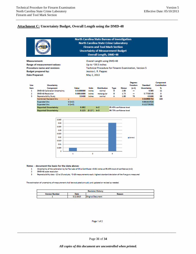
Attachment C: Uncertainty Budget, Overall Length using the DMD-48

Technical Procedure for Firearm Examination North Carolina State Crime Laboratory Firearm and Tool Mark Section
Version 5 Effective Date: 05/10/2013
_____________________________________________________________________________________________________
___________________________________________________________________________________________________
Page 32 of 34
All copies of this document are uncontrolled when printed.

Technical Procedure for Firearm Examination North Carolina State Crime Laboratory Firearm and Tool Mark Section
Version 5 Effective Date: 05/10/2013
_____________________________________________________________________________________________________
___________________________________________________________________________________________________
Page 33 of 34
All copies of this document are uncontrolled when printed.
Attachment D: Uncertainty Budget, Overall Length using a NIST-traceable ruler

Technical Procedure for Firearm Examination North Carolina State Crime Laboratory Firearm and Tool Mark Section
Version 5 Effective Date: 05/10/2013
_____________________________________________________________________________________________________
___________________________________________________________________________________________________
Page 34 of 34
All copies of this document are uncontrolled when printed.