Embed Size (px)
Citation preview

The University of Michigan 2011: It’s a Trap!
i
EXECUTIVE SUMMARY
A long time ago, in a galaxy far, far away, a great voice spoke, leaving the world trembling in their seats. Darth Vader’s eponymous voice reverberates in the minds of tens, if not hundreds, of millions people. From “I am your father” to “escape is not his plan,” we at the University of Michigan know all too well the true strength behind these words.
At the University of Michigan, we take great pride in our history, in the people who came before us and established the precedence for excellence and determination. The University established its College of Engineering in 1854, offering courses in civil engineering. Since its founding, the College has pioneered new technologies, theories, and groundbreaking research. The Michigan Concrete Canoe Team (MCCT) has had a presence within the Civil Engineering Department since 1992, just four years after the founding of the ASCE National Concrete Canoe Competition, and has been an active participant ever since. The team was revived by a group of dedicated civil engineering students, who had heard about the University of Michigan’s participation in several regional competitions in the 1970’s. During its years of competition, MCCT has
consistently placed fourth or fifth overall at regional competition.
This year, MCCT strove to incorporate more sustainable building practices during the fabrication of the canoe to reduce our impact on the environment. The team made use of a male mold for construction, which allowed for a reduction in foam sheets and thus waste. Haydite and Bionic Bubbles were selected as sustainable materials, as Haydite is expanded shale, and Bionic Bubbles are a by-product of coal-combustion. Through the use of more recycled materials, sustainable construction techniques and minimization of waste, MCCT hopes to be a strong contender at this year’s competition.
Table 1: Canoe Specifications
As hosts of this year’s North Central Regional Conference, we will not let up against the competition. The Alliance feared the power and cunning of the Dark Side, leading Admiral Ackbar to famously announce, “It’s a Trap!” It is after this statement that MCCT has named their 2011 canoe, whose specifications are listed in Table 1. This year, we will not sit idly by as other teams come into our house. Through exercise regimens and canoe training, we hope to present a real challenge to our opponents; may the force be with them.
TABLE OF CONTENTS Executive Summary……………………. i Analysis………………………………… 1 Development & Testing………………... 2 Project Management…………………… 3 Construction…………………………… 4 Innovation and Sustainability………….. 6 Organization Chart…………………….. 7 Project Schedule……………………….. 8 Design Drawing……………………….. 9 Appendix A: References………………. A1 Appendix B: Mixture Proportions……... B1 Appendix C: Bill of Materials…………. C1
It’s a Trap! Weight 258.3 lbs Length 20 ft Width 2 ft 7.2 in Depth 1 ft 4 in Hull Thickness 3/4 in Concrete Colors Grey / White Concrete Unit Weight 55.51 lb/ft3 / 64.22 lb/ft3 Compressive Strength 1461 psi / 1546 psi Reinforcement Fiber Glass Mesh
The University of Michigan 2011: It’s a Trap!
1
‐400
‐300
‐200
‐100
0
100
200
300
400
0 2 4 6 8 10 12 14 16 18 20
Moment (ft lbs)
Longitudinal Position (ft from bow)
Coed Sprint Men's SprintWomen's Sprint Men's EnduranceWomen's Endurance Stand
ANALYSIS
MCCT analyzed the primary bending stresses on It’s A Trap! using several different programs. The canoe was modeled by extrapolating from the provided lines drawing using Rhinoceros 4.0. The curves were imported from AutoCAD to create a hull surface. The hull was given an interior
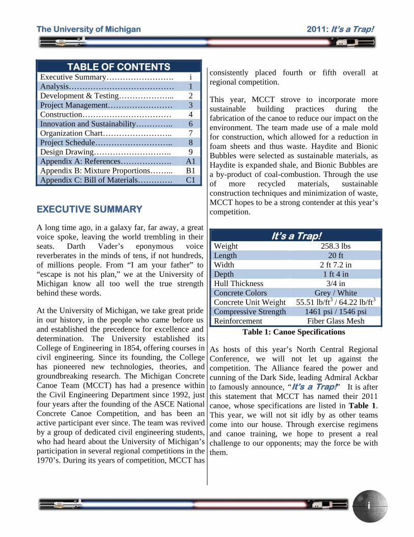
thickness of ¾ inch, a ¾ inch internal gunwale support, and a ¾ inch centerline rib, which extends along the innermost 8 feet of the canoe, a cross section of which is shown in Figure 1. The gunwale supports
and centerline rib increase the moment
of inertia of the canoe, thereby decreasing the stress on the points furthest from the neutral axis. Sectional areas and mass properties of the canoe were determined at 20 points along the length of the canoe. Using curves of best fit to interpolate values between the points, we calculated the section modulus and stresses on the gunwales and keel of the canoe. Mathematical models based on the curves of best fit approximated the mass distribution, neutral axis and moments of inertia. These models were also used to find the distance from the neutral axis to the gunwales and keel, and the section modulus as a function of position.
The canoe hull was imported from Rhinoceros into Formation Design Systems’ Maxsurf Pro Suite, which generated a hydrostatic model of the hull. In Hydromax Ultimate, part of the Maxsurf Suite, five individual load cases were defined, one for each of the race configurations. Male paddlers were conservatively approximated to weigh 180 pounds, and female paddlers approximated at 140 pounds. The canoe weight was calculated to be 258.3 pounds using the mass distribution obtained in Rhinoceros, with a longitudinal centroid of 10 feet
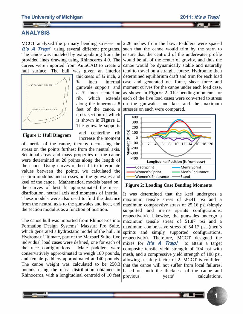
2.26 inches from the bow. Paddlers were spaced such that the canoe would trim by the stern to ensure that the centroid of the underwater profile would be aft of the center of gravity, and thus the canoe would be dynamically stable and naturally tend to travel on a straight course. Hydromax then determined equilibrium draft and trim for each load case and generated net force, shear force and moment curves for the canoe under each load case, as shown in Figure 2. The bending moments for each of the five load cases were converted to stress on the gunwales and keel and the maximum stresses on each were compared.
It was determined that the keel undergoes a maximum tensile stress of 26.41 psi and a maximum compressive stress of 25.16 psi (simply supported and men’s sprints configurations, respectively). Likewise, the gunwales undergo a maximum tensile stress of 51.87 psi and a maximum compressive stress of 54.17 psi (men’s sprints and simply supported configurations, respectively). Therefore, MCCT designed the mixes for It’s A Trap! to attain a target composite tensile yield strength of 104 psi with mesh, and a compressive yield strength of 108 psi, allowing a safety factor of 2. MCCT is confident that the canoe will not suffer from local failures, based on both the thickness of the canoe and previous years’ calculations.
Figure 1: Hull Diagram
Figure 2: Loading Case Bending Moments
The University of Michigan 2011: It’s a Trap!
2
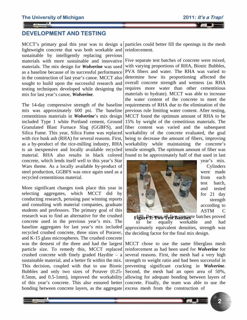
Figure 3: Two Test Batches
DEVELOPMENT AND TESTING
MCCT’s primary goal this year was to design a lightweight concrete that was both workable and sustainable by intelligently replacing previous materials with more sustainable and innovative materials. The mix design for Wolverine was used as a baseline because of its successful performance in the construction of last year’s canoe. MCCT also sought to build upon the successful research and testing techniques developed while designing the mix for last year’s canoe, Wolverine.
The 14-day compressive strength of the baseline mix was approximately 600 psi. The baseline cementitious materials in Wolverine’s mix design included Type 1 white Portland cement, Ground Granulated Blast Furnace Slag (GGBFS), and Silica Fume. This year, Silica Fume was replaced with rice husk ash (RHA) for several reasons. First, as a by-product of the rice-milling industry, RHA is an inexpensive and locally available recycled material. RHA also results in black colored concrete, which lends itself well to this year’s Star Wars theme. As a locally available by-product of steel production, GGBFS was once again used as a recycled cementitious material.
More significant changes took place this year in selecting aggregates, which MCCT did by conducting research, perusing past winning reports and consulting with material companies, graduate students and professors. The primary goal of this research was to find an alternative for the crushed concrete used in the previous year’s mix. The baseline aggregates for last year’s mix included recycled crushed concrete, three sizes of Poraver, and K-15 glass microspheres. The crushed concrete was the densest of the three and had the largest particle size. To remedy this, MCCT replaced crushed concrete with finely graded Haydite – a sustainable material, and a better fit within the mix. This decision, coupled with that to use Bionic Bubbles and only two sizes of Poraver (0.25-0.5mm, and 0.5-1mm), improved the workability of this year’s concrete. This also ensured better bonding between concrete layers, as the aggregate
particles could better fill the openings in the mesh reinforcement.
Five separate test batches of concrete were mixed, with varying proportions of RHA, Bionic Bubbles, PVA fibers and water. The RHA was varied to determine how its proportioning affected the overall concrete strength and wetness (as RHA requires more water than other cementitious materials to hydrate). MCCT was able to increase the water content of the concrete to meet the requirements of RHA due to the elimination of the previous rule limiting water content. After testing, MCCT found the optimum amount of RHA to be 15% by weight of the cemetitious materials. The fiber content was varied and the subsequent workability of the concrete evaluated, the goal being to decrease the amount of fibers, improving workability while maintaining the concrete’s tensile strength. The optimum amount of fiber was found to be approximately half of that used in last
year’s mix. Cylinders
were made from each test batch, and tested for 21 day
strength according to ASTM C
109. Because all five concrete batches proved to be equally workable and had
approximately equivalent densities, strength was the deciding factor for the final mix design.
MCCT chose to use the same fiberglass mesh reinforcement as had been used for Wolverine for several reasons. First, the mesh had a very high strength to weight ratio and had been successful in preventing significant cracking in Wolverine. Second, the mesh had an open area of 50%, allowing for adequate bonding between layers of concrete. Finally, the team was able to use the excess mesh from the construction of
The University of Michigan 2011: It’s a Trap!
3
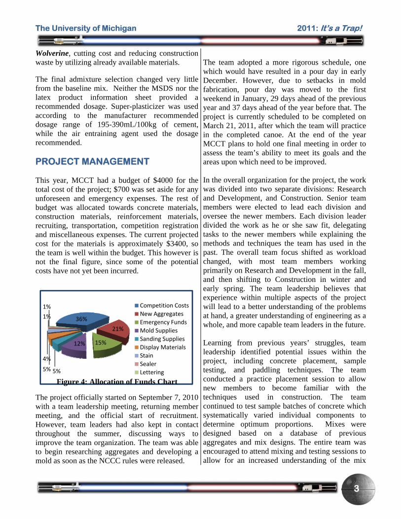
36%
21%
15%12%
5%5%
4%
1%
1% Competition Costs
New Aggregates
Emergency Funds
Mold Supplies
Sanding Supplies
Display Materials
Stain
Sealer
Lettering
Figure 4: Allocation of Funds Chart
Wolverine, cutting cost and reducing construction waste by utilizing already available materials.
The final admixture selection changed very little from the baseline mix. Neither the MSDS nor the latex product information sheet provided a recommended dosage. Super-plasticizer was used according to the manufacturer recommended dosage range of 195-390mL/100kg of cement, while the air entraining agent used the dosage recommended. PROJECT MANAGEMENT This year, MCCT had a budget of $4000 for the total cost of the project; $700 was set aside for any unforeseen and emergency expenses. The rest of budget was allocated towards concrete materials, construction materials, reinforcement materials, recruiting, transportation, competition registration and miscellaneous expenses. The current projected cost for the materials is approximately $3400, so the team is well within the budget. This however is not the final figure, since some of the potential costs have not yet been incurred.
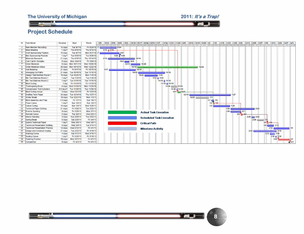
The project officially started on September 7, 2010 with a team leadership meeting, returning member meeting, and the official start of recruitment. However, team leaders had also kept in contact throughout the summer, discussing ways to improve the team organization. The team was able to begin researching aggregates and developing a mold as soon as the NCCC rules were released.
The team adopted a more rigorous schedule, one which would have resulted in a pour day in early December. However, due to setbacks in mold fabrication, pour day was moved to the first weekend in January, 29 days ahead of the previous year and 37 days ahead of the year before that. The project is currently scheduled to be completed on March 21, 2011, after which the team will practice in the completed canoe. At the end of the year MCCT plans to hold one final meeting in order to assess the team’s ability to meet its goals and the areas upon which need to be improved. In the overall organization for the project, the work was divided into two separate divisions: Research and Development, and Construction. Senior team members were elected to lead each division and oversee the newer members. Each division leader divided the work as he or she saw fit, delegating tasks to the newer members while explaining the methods and techniques the team has used in the past. The overall team focus shifted as workload changed, with most team members working primarily on Research and Development in the fall, and then shifting to Construction in winter and early spring. The team leadership believes that experience within multiple aspects of the project will lead to a better understanding of the problems at hand, a greater understanding of engineering as a whole, and more capable team leaders in the future. Learning from previous years’ struggles, team leadership identified potential issues within the project, including concrete placement, sample testing, and paddling techniques. The team conducted a practice placement session to allow new members to become familiar with the techniques used in construction. The team continued to test sample batches of concrete which systematically varied individual components to determine optimum proportions. Mixes were designed based on a database of previous aggregates and mix designs. The entire team was encouraged to attend mixing and testing sessions to allow for an increased understanding of the mix

The University of Michigan 2011: It’s a Trap!
4
6%
29%
9%15%
19%
8%
2%
2%
5%
5%
RecruitingMold FabricationR&DCanoe ConstructionCanoe FinishingPaddlingAnalysisDesign PaperPresentationPoster & Display
Figure 5: Man Hours Break Down
design process. Additionally, all team members were safety trained and familiarized with ASTM standard testing procedures. Canoe paddling practices and weekly workout sessions were held throughout the year, and will culminate in several paddling practices using It’s a Trap!. Major activities during the project could be classified into two groups: Milestone activities and Critical Path events. Milestone activities are considered to be those that, once initiated, mark the beginning of the change from one phase of the project to the next. The following Milestone activities were identified:
Recruit New Members Research Aggregate Materials Mix & Test Sample Batches Cut & Assemble Mold Place Canoe Demold & Sand Canoe Stain & Seal Canoe Create Display & Stand Competition
Critical Path activities were those constrained by the availability of certain facilities or the completion of a prior stage of construction. The critical path activities are as follows:
Mass Meeting Cut Foam Mold Place Canoe Demold Canoe Submit Technical Paper Paddling Practice
Cutting the foam mold, one of the most important critical path activities was heavily constrained by the availability of the CNC router used to cut the foam and the ensuing critical path activity “Place Canoe.” The activity “Place Canoe” was also considered critical and considered to have zero total float, since any delay would leave insufficient time for finishing work on the canoe.
The total number of man-hours is split into three major divisions and is summed up to the total man-hours spent by the team on the project:
Research and Development (includes aggregate, mesh, pigments and plasticizer research, testing, preparing test cylinders, and documenting research findings): 75 man hours
Construction (includes creating 3-D model of canoe, preparing cut-paths, scheduling foam cutting router, cutting foam sheets, assembling and finishing the mold, pouring the canoe, and finishing-testing): 540 man hours
Recruitment (includes work done during summer and prior to school re-opening, creating team website, scheduling MCCT’s presence in college events, editing sending out sponsorship letters, and arranging team-bonding events): 50 man hours
CONSTRUCTION
This year’s construction method differed from the previous two years in that the team chose to use a male mold. The male mold made the concrete easier to place, mitigating the effects of slump on canoe thickness while forcing the team to take special care in maintaining concrete thickness and exterior surface quality. A 3-D model of the canoe mold was created using Rhinoceros 4.0 and then
The University of Michigan 2011: It’s a Trap!
5
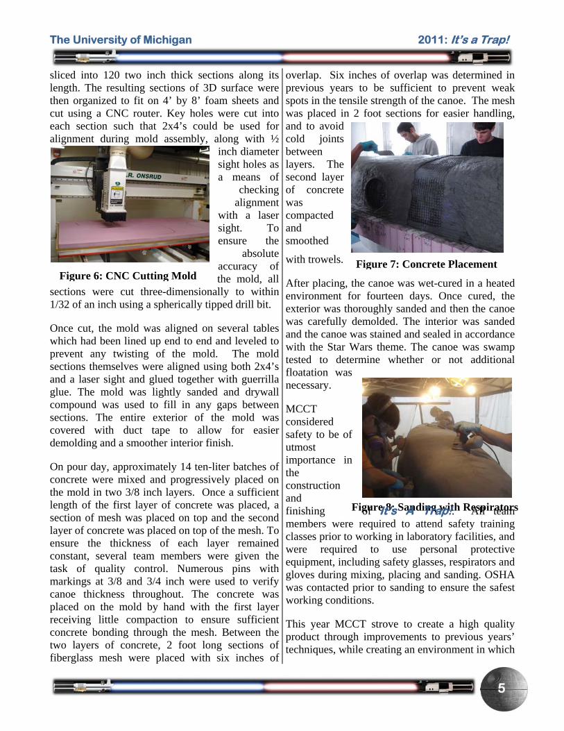
Figure 7: Concrete Placement
Figure 8: Sanding with Respirators
sliced into 120 two inch thick sections along its length. The resulting sections of 3D surface were then organized to fit on 4’ by 8’ foam sheets and cut using a CNC router. Key holes were cut into each section such that 2x4’s could be used for alignment during mold assembly, along with ½
inch diameter sight holes as a means of
checking alignment
with a laser sight. To ensure the
absolute accuracy of the mold, all
sections were cut three-dimensionally to within 1/32 of an inch using a spherically tipped drill bit.
Once cut, the mold was aligned on several tables which had been lined up end to end and leveled to prevent any twisting of the mold. The mold sections themselves were aligned using both 2x4’s and a laser sight and glued together with guerrilla glue. The mold was lightly sanded and drywall compound was used to fill in any gaps between sections. The entire exterior of the mold was covered with duct tape to allow for easier demolding and a smoother interior finish.
On pour day, approximately 14 ten-liter batches of concrete were mixed and progressively placed on the mold in two 3/8 inch layers. Once a sufficient length of the first layer of concrete was placed, a section of mesh was placed on top and the second layer of concrete was placed on top of the mesh. To ensure the thickness of each layer remained constant, several team members were given the task of quality control. Numerous pins with markings at 3/8 and 3/4 inch were used to verify canoe thickness throughout. The concrete was placed on the mold by hand with the first layer receiving little compaction to ensure sufficient concrete bonding through the mesh. Between the two layers of concrete, 2 foot long sections of fiberglass mesh were placed with six inches of
overlap. Six inches of overlap was determined in previous years to be sufficient to prevent weak spots in the tensile strength of the canoe. The mesh was placed in 2 foot sections for easier handling, and to avoid cold joints between layers. The second layer of concrete was compacted and smoothed
with trowels.
After placing, the canoe was wet-cured in a heated environment for fourteen days. Once cured, the exterior was thoroughly sanded and then the canoe was carefully demolded. The interior was sanded and the canoe was stained and sealed in accordance with the Star Wars theme. The canoe was swamp tested to determine whether or not additional floatation was necessary.
MCCT considered safety to be of utmost importance in the construction and
of It’s A Trap!. All team finishing members were required to attend safety training classes prior to working in laboratory facilities, and were required to use personal protective equipment, including safety glasses, respirators and gloves during mixing, placing and sanding. OSHA was contacted prior to sanding to ensure the safest working conditions.
This year MCCT strove to create a high quality product through improvements to previous years’ techniques, while creating an environment in which
Figure 6: CNC Cutting Mold

The University of Michigan 2011: It’s a Trap!
6
Figure 11: MCCT Working in the Wilson Center
newer members could learn from more experienced ones. This resulted in a more unified team, which worked together to solve problems better than any before.
INNOVATIONS AND SUSTAINABILITY
MCCT had specific goals for innovation this year. These goals included: developing a construction method that ensured the proper and accurate assembly of the canoe mold, centralizing the team’s construction and finishing activities, and increasing the amount of sustainable materials used in the concrete mix design.
MCCT made many strides this year in improving construction techniques, particularly to the process of mold assembly. In
past years, MCCT had erroneously assumed that the mold was being constructed on a level surface, aligned along a straight section of 2x4’s. This year, MCCT made
no such assumptions. Several tables were arranged end to end and leveled to create a flat, raised surface upon which to align the mold and construct the canoe. The individual mold sections were aligned using ½
inch diameter sight holes that ran the length of the mold, in conjunction with a laser sight. Having the canoe at waist level also increased productivity and quality control while placing concrete.
This year, instead of placing the canoe in the University of Michigan Civil Engineering structures lab, then transporting it to a separate location for finishing, MCCT utilized the University of Michigan’s Walter E. Wilson Student Team Project Center as the location for all canoe construction and finishing. This allowed the team to mix, place, sand, stain, and seal all in one location, cutting down on time spent transporting the canoe between buildings.
MCCT spent a great deal of time researching and testing materials for use in this year’s concrete mix; these efforts led to the incorporation of Bionic Bubbles, rice husk ash (RHA), and Haydite. Bionic
Bubbles are fine ceramic spheres made from a byproduct from coal combustion. RHA is the ash created from burning rice husk as a fuel for the processing of paddy. The ash is usually dumped in the surrounding environment, but can be used in
concrete as a pozzolan – thereby reducing waste and harm to the environment. Haydite is expanded shale and is considered sustainable as it reduces the volume of material needed to be mined, and the amount of energy used in transportation. These aggregates, in conjunction with the use of Poraver (a recycled glass microsphere), Ground Granulated Blast Furnace Slag (a locally available byproduct of steel production), allowed MCCT to create a mix with 92% sustainable aggregate and 50% sustainable cementitious materials.
Figure 9: Mold on Leveled Tables
Figure 10: Sight Holes
The University of Michigan 2011: It’s a Trap!
7
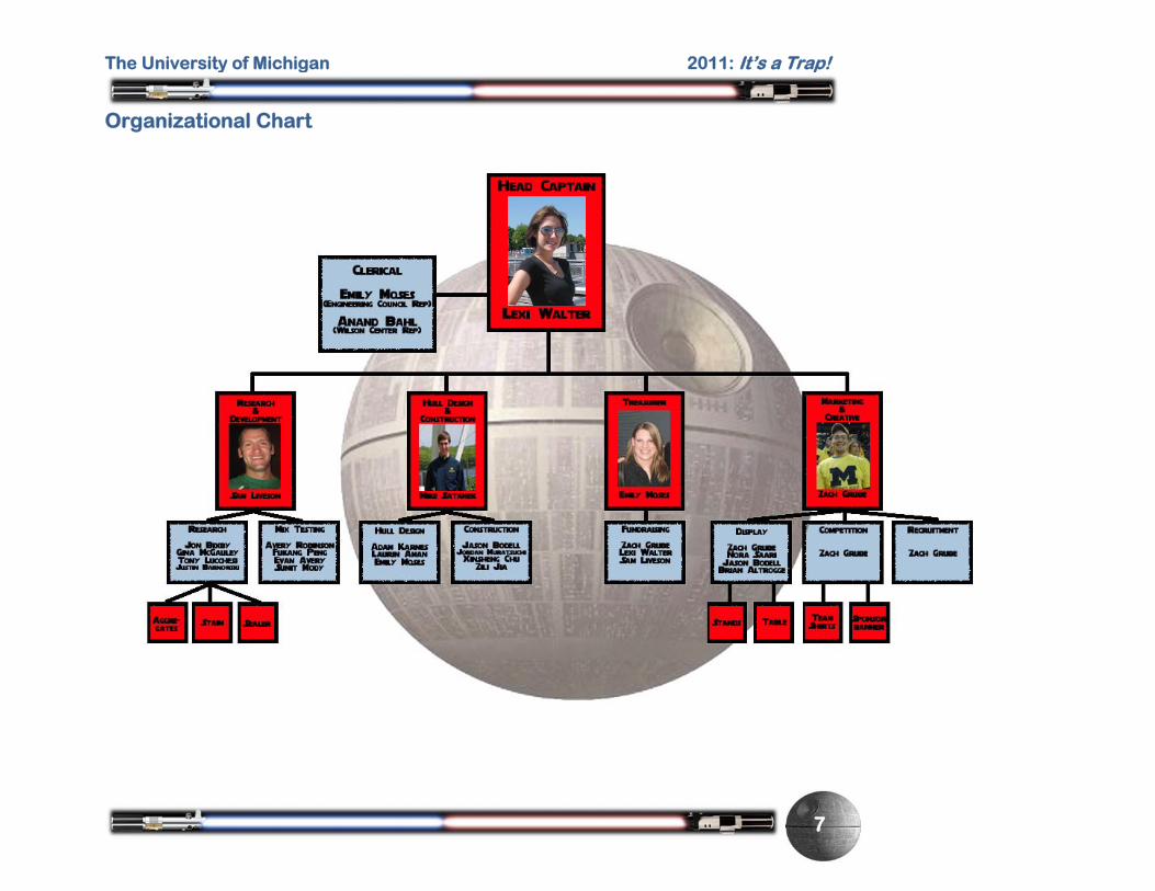
Organizational Chart
The University of Michigan 2011: It’s a Trap!
8
Project Schedule

The University of Michigan 2011: It’s a Trap!
9
Design Drawing

The University of Michigan 2011: It’s a Trap!
A1
Appendix A – References
ACI 318-08, “Building Code Requirements for Structural Concrete,” American Concrete Institute. (copyright 2008).
ASTM C 31/C 31M, “Standard Practice for Making and Curing Concrete Test Specimens in the Field,” ASTM International Book of Standards vol.04.02. (copyright 2005) ASTM C33-03, “Standard Specification for Concrete Aggregates,” ASTM International Book of Standards vol.04.02. (copyright 2005). ASTM C109/C109M-02, “Standard Test Method for Compressive Strength of Hydraulic Cement Mortars,” ASTM International Book of Standards vol.04.01. (copyright 2005). ASTM C496, “Standard Test Method for Splitting Tensile Strength of Cylindrical Concrete Specimens” ASTM International Book of Standards vol. 04.03 (copyright 2005) ASTM C150-04ae1, “Standard Specification for Portland Cement,” ASTM International Book of Standards vol.04.01. (copyright 2005). “Ferrocement and Laminated Cementitious Composites,” Antoine E. Naaman. (copyright 2000). “Poraver Product Specifications” (copyright Poraver North America, 2006) < http://www.poraver.com/02rohstoff/pdf/product_specifi cations.pdf> (accessed October 2009) “3M Scotchlite Glass Bubbles: K and S series Product Information.” (copyright 3M 2006). <http://www.3m.com/microspheres/s_k_1.html> (accessed October 2009).

The University of Michigan 2011: It’s a Trap!
B1
Appendix B – Mixture Proportions

The University of Michigan 2011: It’s a Trap!
B2

The University of Michigan 2011: It’s a Trap!
C1
Appendix C – Bill of Materials
Material Quantity Unit Cost Total Price
Portland Cement Type I 70.1 lbs $0.037/lb $2.59
GGBFS 49.1 lbs $0.025/lb $1.23
RHA 21.0 lbs $0.16/lb $3.36
PVA Fiber 1.3 lbs $2.27/lb $2.95
K15 4.9 lbs $7.77/lb $38.07
Haydite 9.3 lbs $0.05/lb $0.47
Bionic Bubbles 16.7 lbs $8.25/lb $137.80
Poraver 0.5-1 mm 18.5 lbs $0.85/lb $15.73
Poraver 0.25-0.5 12.3 lbs $0.85/lb $10.46
Dow Liquid Latex Modifier 21.0 lbs $8.41/lb $176.60
Glenium 7500 0.35 lbs $1.50/lb $0.53
AE90 0.29 lbs $0.50/lb $0.15
Fiberglass Mesh 83.9 sq ft $0.14/sq ft $11.75
Acid Wash 2 gal $9/gal $18.00
Stain 2 gal $82/gal $164.00
Sealer 2 gal $26/gal $52.00
Paint for Lettering 4 oz $2.50/oz $10.00
Foam Mold, Complete 1 mold $560/mold $560.00
Sand Paper 5 packs $30/pack $150.00
Total Production Cost $1,355.69