Embed Size (px)
Citation preview
Technical Note00840-0200-4408, Rev AA
Testing the Rosemount 5408 Level TransmitterFebruary 2018
Testing the Rosemount™ 5408 Level TransmitterHow to know a product will live up to its promises
The non-contacting radar Rosemount 5408 Level Transmitter was developed to meet many challenging expectations and application conditions while being safe, easy to use, and easy to specify. It is built on a power-efficient FMCW (Frequency Modulated Continuous Wave) platform that incorporates the depth of experience gained over five generations of FMCW-based technology. Our customers expect new devices to solve old problems and to be better than previous units. So how can we know that all the challenges are met?
It all goes back to testing. Starting with one little bit at a time, progressing to a subsystem and then the whole product. Lab tests eventually give way to field tests.
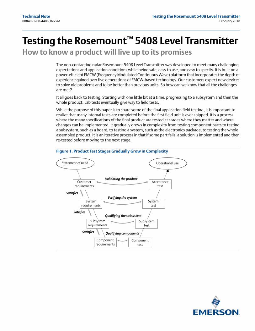
While the purpose of this paper is to share some of the final application field testing, it is important to realize that many internal tests are completed before the first field unit is ever shipped. It is a process where the many specifications of the final product are tested at stages where they matter and where changes can be implemented. It gradually grows in complexity from testing component parts to testing a subsystem, such as a board, to testing a system, such as the electronics package, to testing the whole assembled product. It is an iterative process in that if some part fails, a solution is implemented and then re-tested before moving to the next stage.
Figure 1. Product Test Stages Gradually Grow in Complexity
Statement of need Operational use
Acceptance test
System test
Subsystem test
Component test
Component requirements
Subsystem requirements
System requirements
Customer requirements
Satisfies
Satisfies
Satisfies
Validating the product
Verifying the system
Qualifying the subsystem
Qualifying components
Technical Note00840-0200-4408, Rev AA
Testing the Rosemount 5408 Level TransmitterFebruary 2018
2 Testing the Rosemount 5408 Level Transmitter
The physical product can be divided into three basic subsystems: wetted parts, electronics, and software. Testing of the whole product can be divided into: performance testing, environmental testing, and usability testing.
Much of the testing can be done in-house (List A: In-house functional and verification testing ) while a few tests require an independent lab (List B: External testing ). Internal testing allows parameters to be evaluated independently and under controlled conditions.
List A: In-house functional and verification testingPerformance tests
Accuracy and measurement range
Low DC
Pressure and temperature limits
Power requirements
Power consumption
Transient protection
Vibration
Startup times at temperature extremes
Compatibility with Emerson™ host systems (DeltaV™) and a few non-Emerson systems
Measuring performance can be divided into following categories:
Basic measuring performance in reference condition
Oil and water applications
Low DC products (including solids)
Environmental influence of performance
Long distance measurements > 30 m
Environmental tests
Vibration test
High temperature test
Corrosion test
Process temperature de-rating tests
Process pressure temperature rating
Pressure regulation tests (per required standards)
Process temperature impact on microwave performance
Competitive unit comparisons
List B: External testing EMC
HALT (Highly accelerated life testing)
SIL
Ingress protection
Compatibility with non-Emerson host systems

Technical Note 00840-0200-4408, Rev AA
Testing the Rosemount 5408 Level TransmitterFebruary 2018
1.0 Usability testsThe main strategy for usability tests are to verify the Reference manual, Quick Start Guide and Safety manual. All configurations shall be made by using Rosemount Radar Master Plus if applicable.
Installation tests
Configuration tests
Ease of use
These lists of tests are a simplification of their complexity. For example, the range and accuracy tests are completed on each type and size of antenna, over the intended range and at the normal, maximum, and minimum temperature limits. Numerous samples are used for each set. Similarly, the tests of the pressure and temperature limits include numerous excursions to both the minimum and maximum extremes of each waveguide and each O-ring with numerous samples. Nitrogen and helium leak tests are included to indicate the maximum possible limits beyond the specification limits.
Many application conditions can be tested individually and in a lab environment. This gives the advantage of isolating single potential application challenges and allows them to be addressed. If testing of these parameters were to be conducted in field testing, then other parameters would potentially influence the results. These include:
Measurement near bottom
Influence of polarization orientation
Near zone measurement
Measurement in pipes
Nozzles
Bridles
Influence under EMC disturbance
Mixer
Interface
Foam
Condensation clean/dirty antenna
Low dielectric constant
Bracket mounting
Plastic tank
Disturbance echo
2.0 Field testsWhile there are thousands of possible applications in the industrial world, time and resources do not permit testing of all. Thus, a more practical approach is to identify key parameters that are commonly encountered and to prioritize them. The various field tests of the Rosemount 5408 can be classified into easy, medium, and difficult applications. It is important to thoroughly check key functionality of the device. One function to evaluate is measurement supervision, which is a parallel or supplemental function to the basic level echo analysis. It monitors moving echoes as the level moves pass obstacles that could potentially interfere with the actual measurement. Since the unit includes several algorithms to determine its operational performance it is important to evaluate their functionality. These algorithms include how the unit operates near obstacles, near the bottom or top of the tank, during times when signal loss occurs, or when power is lost. All of these evaluations are included in field tests.
3Testing the Rosemount 5408 Level Transmitter
Technical Note00840-0200-4408, Rev AA
Testing the Rosemount 5408 Level TransmitterFebruary 2018
4 Testing the Rosemount 5408 Level Transmitter
Key questions to consider include:
Is the unit easy to use? Are the pictorial instructions easy to understand? Is the configuration software intuitive?
Will the Rosemount 5408 electronics work with Rosemount 5402 antennas?
Does the Rosemount 5408 work better than legacy units?
Does the Rosemount 5408 work better than competitive units?
Field testing begins when the unit is in an early prototype stage where modifications are expected. These tests often include simpler applications such as storage tanks, sumps, or waste water. Ensuring that the unit physically connects with the customer systems, communication is obtainable, alarms are appropriate, and instructions are easy to follow are all items that can be checked and easily modified during this stage. As the product development evolves, the complexity of the applications increases. An example of this level of testing may include very low dielectric materials such as hydrocarbons, mixing tanks with some small amount of turbulence, longer ranges, and vaporous coating materials such as bitumen.
The last phase of the field testing before production begins includes a more challenging combination of field tests. These would include reactors where turbulence, foam, pressure, and temperature challenges exist, or very long ranges with low dielectric materials, heavy turbulence, vapors, or rapid level changes.
Often, the field tests are done at sites where existing radar units are installed. This allows comparative testing against the legacy products in a field environment and allows the lab tests to be supplemented. In some cases, a different level technology was installed and comparisons were made to that. A summary of the field trials follows here.
3.0 Field test summaries
3.1 Simple but common applicationsFor a radar unit, an easy application would be a water-based fluid because the dielectric is high and thus the signal reflectivity is high. A Parshall flume and a lime dissolver tank falls into this category.
In the case of the Parshall flume, the range of the unit is short and there is only water to measure although it could be moving rapidly. There could be occasional debris or foam passing beneath the radar. To determine the flow rate through the Parshall flume, the measurement must be within a small accuracy band and responsive to rapid changes. In the test site, the Rosemount 5408 was compared to an existing Rosemount 5402 and performed well.
A slightly more complex but still easy application was found in the lime dissolver tank. In this case, the water contains some acid to help dissolve the lime. The crushed lime particles are suspended in the solution and slowly mixed. The mixing creates a small amount of turbulence, thus adding a slight challenge to the application.
Slightly more difficult, but still considered an easy application was a palm oil tank. The tank was heated to prevent solidification of the oil, which creates some vapors. Like many common fuel oils, palm oil is a low dielectric material (DC 1.8) and the storage vessel was tall –13 m (43 ft.), but the Rosemount 5408 performed as expected.
Technical Note 00840-0200-4408, Rev AA
Testing the Rosemount 5408 Level TransmitterFebruary 2018
3.2 A bit more complexMoving up in complexity are applications that have challenges such as lower dielectric materials, mild turbulence, more internal obstacles, and longer ranges. A field test that met this condition was a paper glue mixing vessel. It was a tall, narrow vessel with some agitation due to mixing. The level was run at a high level and with the agitation, splashing caused the antenna to become coated. The mixing also caused the surface to take on a slight conical shape resulting in an angled surface. The glue was a moderate dielectric material. There were usually some islands of foam present. The challenge here was to track the level during fill and empty cycles without locking on the mixing blades. In this case, performance compared well to the Rosemount 5402 even after the antenna became coated.
An example of a low dielectric material is lube oil. Rather than mixing blades, air is injected into the lube oil creating turbulence. Heating coils are in place for heating. Both items present obstacles that must be managed as the tank fills and empties. The heated lube oil gives off vapors and is moderately turbulent. This application triggered a few premature alarms due to some timing of the echo time-out function. Based on these results, refinements were made to the transmitter firmware to enhance the echo tracking function and to the configuration software to make it more intuitive. With the changes implemented, the unit has performed as it should.
In these earlier tests, there were some cases where the device did not correctly track the level for the whole empty sequence. This allowed some additional refinements to be made for improved tracking when the level nears empty tank conditions. The updates were implemented and verified.
Rapid level changes pose a different sort of challenge. While measuring the level accurately within a few millimeters is not crucial, tracking the target reliably is. An example of this challenge is a wet corn surge bin. In this application, wet corn kernels are deposited in the vessel with a level change rate of about 2 ft./min (0.6 m/min). In this case, the Rosemount 5408 outperformed the previous sonar-based technology and tracked the filling process over the full 26 ft. (8 m) range.
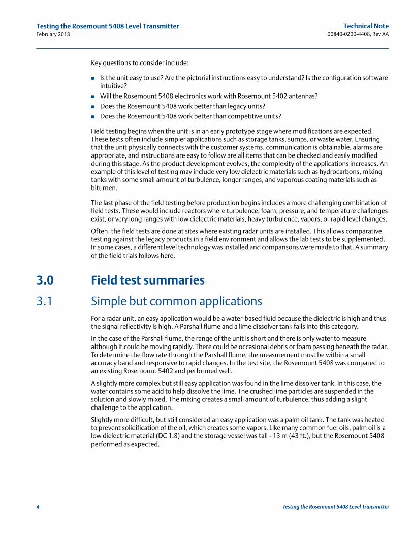
3.3 A new head for an old antennaAnother test challenge was to compare the performance of the Rosemount 5408 to the Rosemount 5402, and to test the ability to use the existing Rosemount 5402 process seal antenna. One example of this test was on a licorice tank. In this case, there are some vapors and there is a mixer blade/scraper that covers the full diameter of the tank. The Rosemount 5402 with a process seal antenna had been installed previously and it tended to lock on the top of the scraper.
Figure 2. Rosemount 5408 Installed with a Rosemount 5402 Process Seal Antenna
5Testing the Rosemount 5408 Level Transmitter
Technical Note00840-0200-4408, Rev AA
Testing the Rosemount 5408 Level TransmitterFebruary 2018
6 Testing the Rosemount 5408 Level Transmitter
The Rosemount 5408 was installed on the existing process seal antenna. When initially installed, the level surface and the top of the scraper were together. As the level slowly dropped, the Rosemount 5408 initially appeared to lock on the scraper. However, after a few minutes, the level measurement dropped to follow the surface. This was a clear indication that the supervision function had worked. As the level fill and empty cycles continued, the unit tracked the surface movement as if the scraper was not there. The supervision function combined with the configuration software guided set up to register echoes reinforced the ease of use functionality of the Rosemount 5408. Not only did it work well with the Rosemount 5402 process seal antenna, but with its enhanced measurement tracking function, it out-performed the Rosemount 5402.
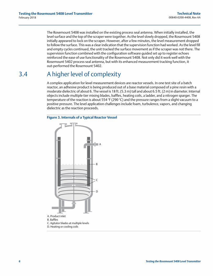
3.4 A higher level of complexityA complex application for level measurement devices are reactor vessels. In one test site of a batch reactor, an adhesive product is being produced out of a base material composed of a pine resin with a moderate dielectric of about 6. The vessel is 18 ft. (5.3 m) tall and about 6.5 ft. (2 m) in diameter. Internal objects include multiple tier mixing blades, baffles, heating coils, a ladder, and a nitrogen sparger. The temperature of the reaction is about 554 °F (290 °C) and the pressure ranges from a slight vacuum to a positive pressure. The level application challenges include foam, turbulence, vapors, and changing dielectric as the reaction proceeds.
Figure 3. Internals of a Typical Reactor Vessel
A. Product inletB. BafflesC. Agitator blades at multiple levelsD. Heating or cooling coils
A
C
D
B
Technical Note 00840-0200-4408, Rev AA
Testing the Rosemount 5408 Level TransmitterFebruary 2018
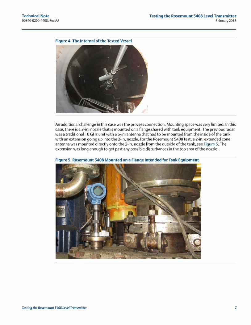
Figure 4. The Internal of the Tested Vessel
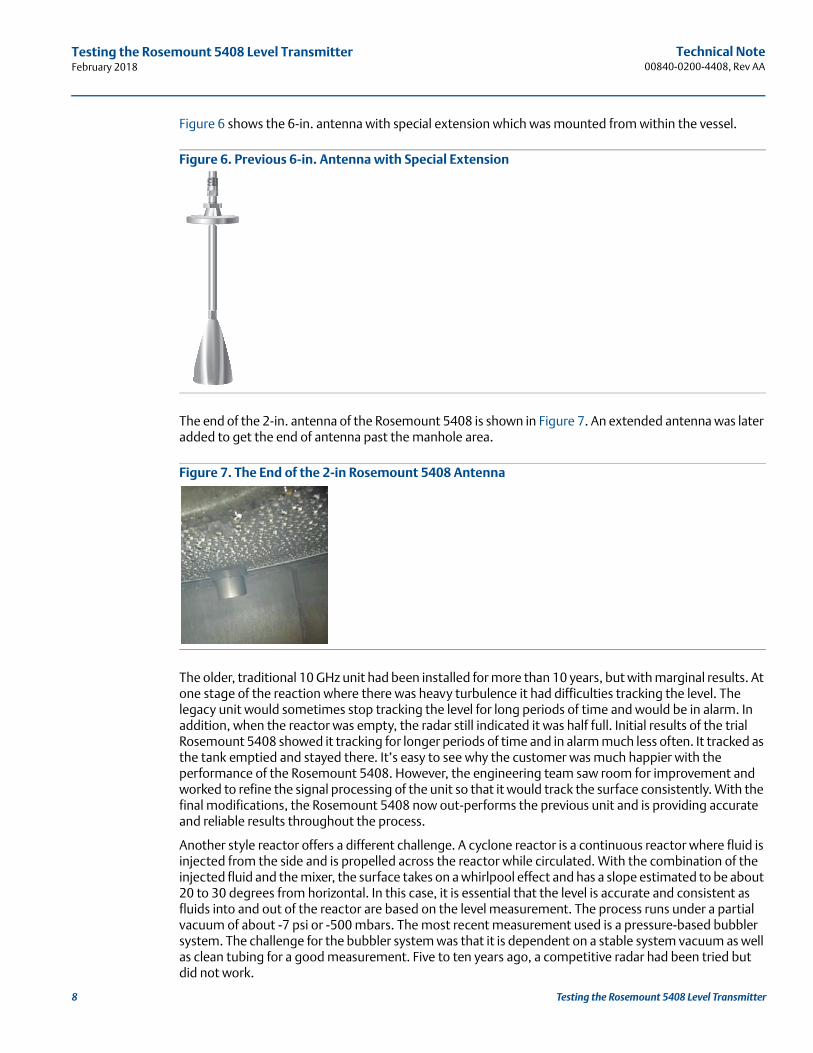
An additional challenge in this case was the process connection. Mounting space was very limited. In this case, there is a 2-in. nozzle that is mounted on a flange shared with tank equipment. The previous radar was a traditional 10 GHz unit with a 6-in. antenna that had to be mounted from the inside of the tank with an extension going up into the 2-in. nozzle. For the Rosemount 5408 test, a 2-in. extended cone antenna was mounted directly onto the 2-in. nozzle from the outside of the tank, see Figure 5. The extension was long enough to get past any possible disturbances in the top area of the nozzle.
Figure 5. Rosemount 5408 Mounted on a Flange Intended for Tank Equipment
7Testing the Rosemount 5408 Level Transmitter
Technical Note00840-0200-4408, Rev AA
Testing the Rosemount 5408 Level TransmitterFebruary 2018
8 Testing the Rosemount 5408 Level Transmitter
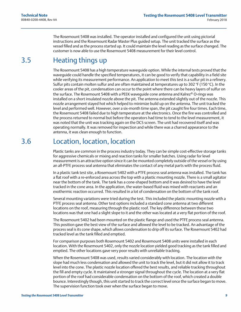
Figure 6 shows the 6-in. antenna with special extension which was mounted from within the vessel.
Figure 6. Previous 6-in. Antenna with Special Extension
The end of the 2-in. antenna of the Rosemount 5408 is shown in Figure 7. An extended antenna was later added to get the end of antenna past the manhole area.
Figure 7. The End of the 2-in Rosemount 5408 Antenna
The older, traditional 10 GHz unit had been installed for more than 10 years, but with marginal results. At one stage of the reaction where there was heavy turbulence it had difficulties tracking the level. The legacy unit would sometimes stop tracking the level for long periods of time and would be in alarm. In addition, when the reactor was empty, the radar still indicated it was half full. Initial results of the trial Rosemount 5408 showed it tracking for longer periods of time and in alarm much less often. It tracked as the tank emptied and stayed there. It’s easy to see why the customer was much happier with the performance of the Rosemount 5408. However, the engineering team saw room for improvement and worked to refine the signal processing of the unit so that it would track the surface consistently. With the final modifications, the Rosemount 5408 now out-performs the previous unit and is providing accurate and reliable results throughout the process.
Another style reactor offers a different challenge. A cyclone reactor is a continuous reactor where fluid is injected from the side and is propelled across the reactor while circulated. With the combination of the injected fluid and the mixer, the surface takes on a whirlpool effect and has a slope estimated to be about 20 to 30 degrees from horizontal. In this case, it is essential that the level is accurate and consistent as fluids into and out of the reactor are based on the level measurement. The process runs under a partial vacuum of about -7 psi or -500 mbars. The most recent measurement used is a pressure-based bubbler system. The challenge for the bubbler system was that it is dependent on a stable system vacuum as well as clean tubing for a good measurement. Five to ten years ago, a competitive radar had been tried but did not work.
Technical Note 00840-0200-4408, Rev AA
Testing the Rosemount 5408 Level TransmitterFebruary 2018
The Rosemount 5408 was installed. The operator installed and configured the unit using pictorial instructions and the Rosemount Radar Master Plus guided setup. The unit tracked the surface as the vessel filled and as the process started up. It could maintain the level reading as the surface changed. The customer is now able to use the Rosemount 5408 measurement for their level control.
3.5 Heating things upThe Rosemount 5408 has a high temperature waveguide option. While the internal tests proved that the waveguide could handle the specified temperatures, it can be good to verify that capability in a field site while verifying its measurement performance. An application to meet this test is a sulfur pit in a refinery. Sulfur pits contain molten sulfur and are often maintained at temperatures up to 302 °F (150 °C). In the cooler areas of the pit, condensation can occur to the point where there can be heavy layers of sulfur on the surface. The Rosemount 5408 with a PEEK waveguide cone antenna and Kalrez® O-rings was installed on a short insulated nozzle above the pit. The antenna extended slightly out of the nozzle. This nozzle arrangement stayed hot which helped to minimize build up on the antenna. The unit tracked the level and performed well. However, over a six-month time span, the pit caught fire four times. Each time, the Rosemount 5408 failed due to high temperature at the electronics. Once the fire was controlled and the process returned to normal but before the operators had time to tend to the level measurement, it was noted that the unit was tracking again on the DCS screen. The unit had recovered itself and was operating normally. It was removed for inspection and while there was a charred appearance to the antenna, it was clean enough to function.
3.6 Location, location, locationPlastic tanks are common in the process industry today. They can be simple cost-effective storage tanks for aggressive chemicals or mixing and reaction tanks for smaller batches. Using radar for level measurement is an attractive option since it can be mounted completely outside of the vessel or by using an all-PTFE process seal antenna that eliminates the contact of any metal parts with the process fluid.
In a plastic tank test site, a Rosemount 5402 with a PTFE process seal antenna was installed. The tank has a flat roof with a re-enforced area across the top with a plastic mounting nozzle. There is a small agitator near the bottom of the tank. The tank has a cone-shaped bottom and it was desired to have the level tracked in the cone area. In the application, the water-based fluid was mixed with reactants and an exothermic reaction occurred. This resulted in a lot of condensation on the bottom of the tank roof.
Several mounting variations were tried during the test. This included the plastic mounting nozzle with a PTFE process seal antenna. Other test options included a standard cone antenna at two different locations on the roof, measuring through the plastic roof. The key difference between these two locations was that one had a slight slope to it and the other was located at a very flat portion of the roof.
The Rosemount 5402 had been mounted on the plastic flange and used the PTFE process seal antenna. This position gave the best view of the surface and allowed the level to be tracked. An advantage of the process seal is its cone shape, which allows condensation to drip off its surface. The Rosemount 5402 had tracked level as the tank filled and emptied.
For comparison purposes both Rosemount 5402 and Rosemount 5408 units were installed in each location. With the Rosemount 5402, only the nozzle location yielded good tracking as the tank filled and emptied. The other locations gave very poor results with unreliable tracking.
When the Rosemount 5408 was used, results varied considerably with location. The location with the slope had much less condensation and allowed the unit to track the level, but it did not allow it to track level into the cone. The plastic nozzle location offered the best results, and reliable tracking throughout the fill and empty cycle. It maintained a stronger signal throughout the cycle. The location at a very flat portion of the roof had considerable condensation on the bottom of the roof, which created a double bounce. Interestingly though, this unit started to track the correct level once the surface began to move. The supervision function took over when the surface began to move.
9Testing the Rosemount 5408 Level Transmitter

Technical Note00840-0200-4408, Rev AA
Testing the Rosemount 5408 Level TransmitterFebruary 2018
10 Testing the Rosemount 5408 Level Transmitter
Conclusion: install the unit where it can see the surface throughout the whole cycle. The Rosemount 5408 can be used either with a process seal antenna installed in a flange connection or outside the roof installed with a standard cone antenna with a bracket.
When finding an appropriate location on the tank for the transmitter, the conditions of the tank must be carefully considered. Consider the following guidelines when mounting the transmitter:
For optimal performance, the transmitter should be installed in locations with a clear and unobstructed view of the product surface.
The transmitter should be mounted with as few internal structures as possible within the signal beam.
Do not install the transmitter in the center of the tank.
Do not mount close to or above the inlet stream.
Figure 8. Recommended Mounting Position
3.7 And what about foam?Foam is a constant source of questions for the radar user. Light foam over a highly reflective material surface may be manageable by many units. As the foam becomes more dense or thick, it becomes more difficult to handle. In the worst case, the foam can absorb the signal and very little is reflected to the transmitter. The other consideration is whether the signal is reflected from the top of the foam or the liquid surface. It can be difficult to know. Often though, the foam will sufficiently attenuate the signal such that very little signal remains for tracking purposes. In these cases, the key is to have a strong enough signal so there is sufficient margin to provide an echo for tracking. In the field testing discussed here, foam has played a part in some of the tests but most notably the batch reactor where it appears during certain stages and the Rosemount 5408 could track during its presence.
One other field test, chosen because of the constant presence of a foam layer, offered another opportunity. In this case, the application was in a filter backwater pit in a refinery. The water was dirty and had a constant, thick layer of foam. The Rosemount 5402 provided marginal results and would occasionally lose the signal. The Rosemount 5408 with its much higher signal amplitude could track the surface reliably despite the constant layer of foam.
Technical Note 00840-0200-4408, Rev AA
Testing the Rosemount 5408 Level TransmitterFebruary 2018
3.8 SummaryThe Rosemount 5408 has had excellent field test results. It is easy for a user to install with the pictorial guidelines and configuration software is intuitive for the newer user. With results and feedback from the field tests, improvement in both the transmitter software and configuration software were identified and implemented. Its measurement supervision function can ensure that the unit finds and tracks the correct target with minimal user intervention. It can be reliably used with Rosemount 5402 antennas and it out-performs both the 2-wire pulse units and the traditional 4-wire FMCW units.
11Testing the Rosemount 5408 Level Transmitter

Technical Note00840-0200-4408, Rev AA
February 2018
Global HeadquartersEmerson Automation Solutions 6021 Innovation Blvd.Shakopee, MN 55379, USA
+1 800 999 9307 or +1 952 906 8888+1 952 949 7001 [email protected]
North America Regional OfficeEmerson Automation Solutions 8200 Market Blvd.Chanhassen, MN 55317, USA
+1 800 999 9307 or +1 952 906 8888+1 952 949 7001 [email protected]
Latin America Regional OfficeEmerson Automation Solutions1300 Concord Terrace, Suite 400Sunrise, FL 33323, USA
+1 954 846 5030+1 954 846 [email protected]
Europe Regional OfficeEmerson Automation Solutions Europe GmbHNeuhofstrasse 19a P.O. Box 1046CH 6340 BaarSwitzerland
+41 (0) 41 768 6111+41 (0) 41 768 6300 [email protected]
Asia Pacific Regional OfficeEmerson Automation Solutions1 Pandan CrescentSingapore 128461
+65 6777 8211+65 6777 0947 [email protected]
Middle East and Africa Regional OfficeEmerson Automation Solutions Emerson FZE P.O. Box 17033Jebel Ali Free Zone - South 2Dubai, United Arab Emirates
+971 4 8118100+971 4 8865465 [email protected]
Linkedin.com/company/Emerson-Automation-Solutions
Twitter.com/Rosemount_News
Facebook.com/Rosemount
Youtube.com/user/RosemountMeasurement
Google.com/+RosemountMeasurement
Emerson Terms and Conditions of Sale are available upon request.The Emerson logo is a trademark and service mark of Emerson Electric Co. Rosemount is a mark of one of the Emerson family of companies. All other marks are the property of their respective owners.© 2018 Emerson. All rights reserved.