Embed Size (px)
Citation preview

TECHNICAL MANUAL OPERATOR AND FIELD MAINTENANCE MANUAL
FOR
DBAL-I² (DUAL BEAM AIMING LASER-INTELLIGENT²) P/N 40072___ <50mW IR Pointer & <50mW IR Pointer/Illuminator P/N 50410___ <50mW IR Pointer & <200mW IR Pointer/Illuminator
70 Garden Court • Monterey, CA 93940 U.S.A.
Tel 831-373-0701 / 800-235-2162 (outside CA) • Fax 831-373-0903 [email protected] • www.laserdevices.com


a
0 0
SAFETY SUMMARY
WARNING
INVISIBLE LASER RADIATION AVOID DIRECT EXPOSURE TO THE BEAM
INFRARED LASER POINTER (Class IIIb) <50mW | WAVELENGTH: 835nm (±2.5nm)
INFRARED LASER POINTER/ILLUMINATOR (Class IIIb) <50mW or <200mW | WAVELENGTH: 835nm (±2.5nm)
• DO NOT stare into the laser beam. • DO NOT look into the laser beam through binoculars or telescopes. • DO NOT point the laser beam at mirror-like surfaces. • DO NOT shine the laser beam into other individual’s eyes.

b
SAFETY SUMMARY, continued
Table 0-1 Safety Data
LASER Power Output
SAFETY CLASS
NOHD (m)
IR POINTER - Low Power IR POINTER - High Power
<1mW <5mW
IIIb 22.7m56.8m
IR POINTER - Low Power IR POINTER - High Power
<1mW <50mW
IIIb 22.7m
199.7mIR ILLUM - Low Power IR ILLUM - High Power
<1mW <50mW
IIIb 13.63mm
114mIR ILLUM - Low Power IR ILLUM - High Power
<5mW <200mW
IIIb 34.06mm
1231m DEFINITION OF THE FOLLOWING ALERTS THROUGHOUT THIS MANUAL:
WARNING
Identifies a clear danger to the person doing that procedure.
CAUTION Identifies risk of damage to the equipment.
NOTE Used to highlight essential procedures, conditions, statements, or convey important instructional data to the user.

c
WARNING
Be sure the weapon is CLEAR and on SAFE before proceeding.
WARNING
RISK OF DETECTION BY ENEMY To reduce the risk of detection by an enemy using a Night Vision Device (NVD), avoid prolonged activation of the DBAL-I2.
WARNING
The infrared beam is more detectable to an enemy using a NVD when used in smoke, fog and rain. Avoid prolonged activation of the DBAL-I2 in these conditions.
WARNING
DO NOT store the DBAL-I2 with the battery installed.
WARNING
The High Power Modes are blocked with a safety screw.
WARNING
To operate the DBAL-I2 in the High Power modes the blue safety screw must be removed from the back of the unit. The Armorer will remove and store the safety screw.

d
SAFETY SUMMARY, continued
WARNING
All directions, such as CW and CCW, are given from the shooter’s point of view, as though the DBAL-I² were weapon-mounted.
WARNING
The DBAL-I² is powered by one 3V CR123A Lithium Manganese Dioxide (Li/MnO2) battery, or by one 1.5V AA Alkaline battery. The following safety precautions apply when handling lithium batteries: DO NOT short circuit, puncture, or disassemble DO NOT attempt to recharge NEVER dispose of lithium batteries in a fire, or in any way
expose lithium batteries to excessive heat Batteries may explode if disassembled, crushed,
recharged, or exposed to high temperatures Avoid mechanical or electrical abuse Prior to use, inspect all batteries for cracks, leakage, or
bulging NEVER install a defective battery in the DBAL-I² DO NOT install incorrectly Store lithium batteries at room temperature Refer to applicable federal, state, and local laws and
regulations for proper disposal of the 3V CR123A Lithium Batteries
WARNING
Be sure the weapon is CLEAR and on SAFE before proceeding.

e
WARNING
Make sure the Activation Mode Selector Switch is in the OFF position before inspecting the Exit Port Lenses of the DBAL-I².
WARNING
If the Activation Selector Switch is not in the OFF position, the laser can be inadvertently activated by depressing the fire button on the top of the housing.
WARNING
If the Laser Borelight System (LBS) is used to boresight the DBAL-I², be sure to remove the LBS from the weapon prior to firing.
WARNING
NEVER boresight in the High Power mode of operation.
CAUTION
DO NOT over-adjust the laser adjusters by forcing them beyond their end of travel.
CAUTION
DO NOT defocus the infrared illuminator by forcing it beyond its normal end of travel.
CAUTION
DO NOT overtighten the Safety Screw when installing it into the DBAL-I² housing as you may strip the housing threads.

f
SAFETY SUMMARY, continued
CAUTION
Prior to submerging the DBAL-I², make sure the infrared illuminator focusing knob has been adjusted in a CCW direction to the focus point.
CAUTION Use ONLY authorized weapons cleaning supplies on the DBAL-I² or permanent damage may occur.
CAUTION DO NOT remove the Remote Cable Switch by pulling on the cable.
CAUTION
To prevent damage to the IR ILLUM Exit Port Cover, open the Dust Cover before turning the knob to adjust the focus.

i
TABLE OF CONTENTS
SAFETY SUMMARY........................................................................ a TABLE OF CONTENTS .................................................................... i LIST OF FIGURES........................................................................... ii HOW TO USE THIS MANUAL ........................................................ iv
CHAPTER I ........................................................................................1-1 GENERAL INFORMATION...........................................................1-1
CHAPTER II .......................................................................................2-1 EQUIPMENT DESCRIPTION .......................................................2-1
CHAPTER III ......................................................................................3-1 SECTION I OPERATING INSTRUCTIONS ..................................3-1 SECTION II MOUNTING PROCEDURES ..................................3-20 SECTION III ZEROING PROCEDURES.....................................3-24
CHAPTER IV......................................................................................4-1 SECTION I OPERATOR PREVENTIVE MAINTENANCE CHECKS .....................................................................................4-1 SECTION II OPERATOR TROUBLESHOOTING.........................4-7 SECTION III OPERATOR MAINTENANCE..................................4-9
CHAPTER V.......................................................................................5-1 SECTION I UNIT TROUBLESHOOTING......................................5-1 SECTION II UNIT MAINTENANCE...............................................5-3 SECTION III SERVICE/PACKING AND UNPACKING .................5-7 REPAIR PARTS ........................................................................... A-1

ii
LIST OF FIGURES
Figure 1-1 DBAL-I² in use...................................................................1-1 Figure 2-1 DBAL-I² Features ..............................................................2-2 Figure 2-2 DBAL-I² Major Components..............................................2-4 Figure 3-1 DBAL-I² Battery Installation...............................................3-3 Figure 3-2 Activation Mode Selector Switch.......................................3-5 Figure 3-3 Safety Screw Installed (Shown in Training Mode) ............3-7 Figure 3-4 Integrated Momentary Activation Switch ..........................3-8 Figure 3-5 Laser Activation/Low Battery LED ....................................3-9 Figure 3-6 Installation of Remote Cable Switch ...............................3-11 Figure 3-7 The IR ILLUM Focusing Knob ........................................3-13 Figure 3-8 OIR, or Pattern Generator...............................................3-14 Figure 3-9 Installation of OIR, or Pattern Generator ........................3-15 Figure 3-10 Adjusters for Illumination Beam ....................................3-17 Figure 3-11 Adjusters for Aiming Beam ...........................................3-17 Figure 3-12 Adjuster Guard Markings ..............................................3-17 Figure 3-14 Laser Borelight System 10m Zeroing Target ................3-32 Figure 3-15 Commercial 25m Zeroing Target ..................................3-36 Repair Parts ...................................................................................... A-1

iii
LIST OF TABLES
Table 1-1 Safety Data ........................................................................... b Table 2-1 DBAL-I² Features ...............................................................2-2 Table 2-2 Weight, Dimensions, and Performance .............................2-3 Table 2-3 DBAL-I² Major Components...............................................2-5 Table 3-1 Activation and Mode Selector Switch Functions ................3-6 Table 3-2 Adjuster Rotation and Shot Group Movement for the Aiming Lasers (Top Mounted)........................................................3-18 Table 3-3 Adjuster Rotation and Illumination Area Movement for the IR ILLUM (Right Mounted) .......................................................3-19 Table 3-4 Factory Neutral Preset .....................................................3-26 Table 3-5 DBAL-I² Mounting Configurations and Weapon Offsets ..3-27 Table 4-1 Preventive Maintenance Checks and Services..................4-4 Table 5-1 Unit Troubleshooting..........................................................5-2 Table A-1 Repair Parts List (DBAL-I²) ............................................... A-2

iv
HOW TO USE THIS MANUAL Usage You must familiarize yourself with the entire manual before operating the equipment. Read the complete maintenance task before performing maintenance and follow all WARNINGS, CAUTIONS and NOTES. Manual Overview This manual contains sections for Operating and Maintaining the DBAL-I². Appendix A Repair Parts

1-1
1 1
CHAPTER I GENERAL INFORMATION
Figure 1-1 DBAL-I² in use

1-2
GENERAL INFORMATION, continued 1.1.a Type of Manual: Operator and Field Maintenance Manual. 1.1.b Model Number and Equipment Name: DBAL-I², Dual Beam Aiming Laser-Intelligent². 1.1.c Purpose of Equipment: To covertly illuminate and direct fire using an infrared laser pointer (IR POINT) and an infrared laser illuminator (IR ILLUM) for operators equipped with a Night Vision Device (NVD). 1.2 REPORTING EQUIPMENT IMPROVEMENT RECOMMENDATIONS If your DBAL-I² needs improvement, let us know. Mail your comments to Laser Devices, Inc., 70 Garden Court, Monterey, CA 93940, USA, send a fax to 831-373-0903, or email [email protected]. 1.3 WARRANTY INFORMATION This item shall conform to design, manufacturing, and performance requirements and be free from defects in material and workmanship for one (1) year from the date of manufacture. This warranty does not protect against damage due to misuse or mishandling.

1-3
1.4 CROSS REFERENCES Common Name Official Name Allen Wrench................ Socket Head Screw Key Battery Cap .................. Battery Box Cover Shipping Case.............. Textile Bag Cotton Swab ................ Disposable Applicator Neoprene Jack Plug..... Plug Assembly O-Ring.......................... Gasket Safety Screw ................ Electrical Dial-Knob Lock Pattern Generator ........ Optical Instrument Reticle Lens Covers ................ Exit Port Covers Paddle Switch .............. Remote Cable Switch Battery.......................... 3V CR123A or 1.5V AA (depending on option purchased) Technical Manual Operator and Field Maintenance Manual Tape Fastener Loop..... Fastener, Loop Tape Tape Fastener Hook .... Fastener, Hook Tape

1-4
GENERAL INFORMATION, continued
1.5 LIST OF ABBREVIATIONS C......................Celsius (Centigrade) CCW................Counter-clockwise cm....................Centimeters CTA .................Common Table of Allowance CW...................Clockwise EA....................Each F ......................Fahrenheit HI .....................High ILLUM..............Illuminator in......................Inches IR.....................Infrared LBS..................Laser Borelight System LED..................Light Emitting Diode LO....................Low m .....................Meter Max..................Maximum Mfr ...................Manufacturer Min...................Minimum MOM................Momentary mm...................Millimeter mrad ................Milliradians mW ..................Milliwatts nm....................Nanometers No....................Number NOHD ..............Nominal Ocular Hazard Distance NSN.................National Stock Number NVD.................Night Vision Device O.D. ................Optical Density OIR .................Optical Instrument Reticle POINT..............Pointer PWR ................Power QTY .................Quantity RMA.................Return Material Authorization SR....................Service Representative TM ...................Technical Manual VIS...................Visible

2-1
2 2
CHAPTER II EQUIPMENT DESCRIPTION
2.1 SYSTEM DESCRIPTION The DBAL-I² is a Class IIIb laser device that features an IR POINT and IR ILLUM for use with a NVD. The IR beams can be operated individually or in combination, in both low power (LO PWR) and high power (HI PWR) settings. The DBAL-I² is equipped with an IR POINT for precise aiming of the weapon and a separate IR ILLUM for illumination of the target or target area. The IR ILLUM provides supplemental illumination of the target area and is equipped with an adjustable bezel to vary the size of the illumination beam. The DBAL-I² can be used as either a handheld pointer/illuminator or can be weapon mounted using a quick release mount. In the weapon mounted mode, the DBAL-I² can be used to accurately direct fire as well as illuminate and identify targets. When the Safety Screw is installed in the rear of the DBAL-I² housing, it prevents the operator from accessing the HIGH POWER modes of operation.

2-2
EQUIPMENT DESCRIPTION, continued 2.1 SYSTEM DESCRIPTION, continued
Figure 2-1 DBAL-I² Features
Table 2-1 DBAL-I² Features
ITEM DESCRIPTION 1 IR ILLUM Adjusters 2 IR ILLUM Laser Exit Port 3 3V CR123A Battery Cap and Compartment 4 IR POINT Laser Exit Port 5 Quick Release Mount 6 IR POINT Adjusters
5 3
1
4
2
6

2-3
2.2 GENERAL CHARACTERISTICS
Table 2-2 Weight, Dimensions, and Performance WEIGHT
7.2 oz with one 3V CR123A battery
201.3 grams DIMENSIONS
Length 3.5 in. / 8.9 cm Width 2.75 in. / 7 cm Height (including mount) 1.75 in. / 4.4 cm
PERFORMANCE Laser Wavelength
IR POINT or IR ILLUM 835nm (±2.5nm) Output Power
IR POINT or IR ILLUM <50mW IR ILLUM <200mW
Beam Divergence IR POINT 0.3 mrad IR ILLUM 0.5 - 75 mrad
5.5 Hours on Dual High (3V CR123A)Battery Life
1.0 Hours on IR Dual High (1.5V AA) POINT & ILLUM RANGE (Starlight Conditions)
IR POINT or IR ILLUM <50mW
2000m
IR ILLUM <200mW 5000m

2-4
EQUIPMENT DESCRIPTION, continued 2.3 DESCRIPTION OF MAJOR COMPONENTS
Figure 2-2 DBAL-I² Major Components

2-5
Table 2-3 DBAL-I² Major Components ITEM DESCRIPTION
1 Tape Fastener Loop 5/8” (Black)
2 Tape Fastener Hook ½" (Black) (attached to remote cable switch)
3 Remote Cable Switch, 7” 4 Optical Instrument Reticle (OIR) (set of 5) 5 Battery, 3V CR123A (must be used with associated battery cap) 6 Battery, 1.5-volt AA (must be used with associated battery cap) 7 DBAL-I² Assembly (shown with 1.5-volt AA battery cap) 8 Shipping Case 9 Operator and Field Maintenance Manual

2-6
EQUIPMENT DESCRIPTION, continued
2.3 DESCRIPTION OF MAJOR COMPONENTS, continued 2.3.a Tape Fastener Loop The Tape Fastener Loop is provided to secure the Remote Cable Switch to the weapon in a position convenient to the soldier. 2.3.b Tape Fastener Hook The Tape Fastener Hook is pre-attached by the manufacturer to the pressure pad switch. 2.3.c Remote Cable Switch The 7” Remote Cable Switch allows the user to activate the DBAL-I² in a momentary (MOM) mode by depressing the pressure pad once. Double-clicking the pressure pad will activate the DBAL-I² continuously for 5 minutes. Pressing the pressure pad again will return the unit to momentary activation. The pressure pad provides a tactile (silent) click that indicates when the switch has been activated. 2.3.d Optical Instrument Reticle (OIR) (Pattern Generators)
NOTE OIRs are not designed for accurate aiming of the weapon.
The Optical Instrument Reticles (OIR), also called Pattern Generators, are used for command and control. When an OIR is installed in front of the IR POINT or IR ILLUM that has been focused to a point, it will project the shape of a circle, triangle, plus sign, square, or T-shape. 2.3.e Battery One 3V CR123A battery or one 1.5V AA battery can be used as a power supply for operating the DBAL-I²(model dependent). The use of a high-quality battery is recommended.

2-7
2.3.f DBAL-I² Assembly The DBAL-I² device provides an IR POINT and adjustable focus IR ILLUM. The device is used for aiming, signaling, command and control, and for purposes of supplying supplemental IR illumination. 2.3.g Shipping Case The DBAL-I² is provided with a Shipping Case. 2.3.h Operator and Field Maintenance Manual
NOTE You must read the entire Operator and Field Maintenance Manual before operating the DBAL-I² and follow all WARNINGS, CAUTIONS and NOTES.
The Operator and Field Maintenance Manual provides safety information, equipment information, operating instructions, mounting procedures, zeroing procedures, and operator and unit maintenance procedures.


3-1
3 3
CHAPTER III SECTION I OPERATING INSTRUCTIONS
3.1 GENERAL
WARNING
INVISIBLE LASER RADIATION AVOID DIRECT EXPOSURE TO THE BEAM
INFRARED LASER POINTER (Class IIIb) <50mW | WAVELENGTH: 835nm (±2.5nm)
INFRARED LASER POINTER/ILLUMINATOR (Class IIIb) <50mW or <200mW | WAVELENGTH: 835nm (±2.5nm)
• DO NOT stare into the laser beam. • DO NOT look into the laser beam through binoculars or telescopes. • DO NOT point the laser beam at mirror-like surfaces. • DO NOT shine the laser beam into other individual’s eyes.

3-2
OPERATING INSTRUCTIONS, continued
3.2 DBAL-I² CONTROLS AND INDICATORS 3.2.a Battery Installation
NOTE Loss or removal of the O-ring from the battery cap may allow water to enter the DBAL-I².
Unscrew the battery cap in a CW direction. Remove and properly discard the spent battery. Inspect the battery compartment for dirt, moisture and corrosion. Clean the battery compartment as needed (refer to Paragraph 4.3.c). Inspect the O-ring seal on the battery cap to make sure it is free of sand and dirt particles and that it has not been damaged (see Paragraph 4.3.d). Install the battery (both 3V CR123A and 1.5V AA batteries are installed the same way) as indicated by the marking on the DBAL-I² housing. Reinstall the battery cap and hand tighten in a CCW direction.

3-3
Figure 3-1 DBAL-I² Battery Installation
Battery Orientation Marking

3-4
3.2.b Activation Mode Selector Switch
WARNING
The High Power Modes of operation are blocked with a blue Safety Screw.
NOTE The DBAL-I² will not operate if the rotary switch is not aligned with the marked switch position. In extreme cold temperatures the switch may offer more resistance.
The Activation Mode Selector Switch is located on the left rear of the DBAL-I² housing. It is used to select between the various modes of operation when the Remote Cable Switch or the Integrated Momentary Activation Switch is depressed. The Activation Mode Selector Switch has six (6) positions. See Table 3-1.

3-5
Figure 3-2 Activation Mode Selector Switch
Activation Mode Selector Switch

3-6
OPERATING INSTRUCTIONS, continued
3.2 DBAL-I² CONTROLS AND INDICATORS, continued
3.2.b Activation Mode Selector Switch, continued
Table 3-1 Activation and Mode Selector Switch Functions Switch Position
Marking Use Remarks
1 OFF OFF The DBAL-I² will not operate
2 A/L (AIM LO)
LOW IR POINT is activated when the Remote Cable Switch or Integrated Momentary Activation switch is pressed
Used for bore sighting and training
3 D/L (DUAL LO)
LOW IR POINT & LOW IR ILLUM are activated when the Remote Cable Switch or Integrated Momentary Activation switch is pressed
Primarily used to boresight the laser, in low light conditions, and for training.
4 A/H (AIM HI)
HIGH IR POINT is activated when the Remote Cable Switch or Integrated Momentary Activation switch is pressed
Used for pointing / aiming at long ranges. DO NOT use for bore sighting the weapon.
5 L/H (DUAL LO/HI)
LOW IR POINT & HIGH IR ILLUM are activated when the Remote Cable Switch or Integrated Momentary Activation switch is pressed
Illuminates the target area and provides an aiming point to accurately engage the target. For pointing /aiming indoors and outdoors at close range.
6 H/H
(DUAL HI/HI)
HIGH IR POINT & HIGH IR ILLUM are activated when the Remote Cable Switch or Integrated Momentary Activation switch is pressed
Illuminates the target area and provides an aiming point to accurately engage the target. For pointing /aiming indoors and outdoors and at long ranges.
3-7
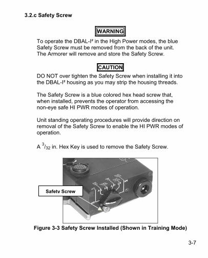
3.2.c Safety Screw
WARNING
To operate the DBAL-I² in the High Power modes, the blue Safety Screw must be removed from the back of the unit. The Armorer will remove and store the Safety Screw.
CAUTION
DO NOT over tighten the Safety Screw when installing it into the DBAL-I² housing as you may strip the housing threads. The Safety Screw is a blue colored hex head screw that, when installed, prevents the operator from accessing the non-eye safe HI PWR modes of operation. Unit standing operating procedures will provide direction on removal of the Safety Screw to enable the HI PWR modes of operation.
A 3/32 in. Hex Key is used to remove the Safety Screw.
Figure 3-3 Safety Screw Installed (Shown in Training Mode)
Safety Screw

3-8
OPERATING INSTRUCTIONS, continued
3.2 DBAL-I² CONTROLS AND INDICATORS, continued 3.2.d Integrated Momentary Activation Switch The Integrated Momentary Activation Switch is located on the top of the DBAL-I² housing below the word FIRE. Firmly pressing and holding the switch activates the DBAL-I² laser function selected by the Activation Mode Selector Switch. When the switch is released, the DBAL-I² turns off. Double-clicking the Integrated Momentary Activation Switch will activate the DBAL-I² in a continuous ON mode for 5 minutes. Pressing the Integrated Momentary Activation Switch once again will return the unit to the momentary mode.
Figure 3-4 Integrated Momentary Activation Switch
Integrated Momentary Activation Switch

3-9
3.2.e Activation Indicator A green LED is located on the rear housing between the Activation Mode Selector Switch and the remote cable receptacle. When lit, it indicates that the DBAL-I² is actively emitting laser energy. It also acts as a Low Battery Indicator. When the Activation Mode Selector Switch is turned to an operating position, the LED will light up if either the Remote Cable Switch or Integrated Momentary Activation Switch is pressed and held, indicating that the laser is ON. The LED will remain lit until the Integrated Momentary Activation Switch or Remote Cable Switch is released. When the Remote Cable Switch or Integrated Momentary Activation Switch has been double-clicked, the LED will light up indicating that the laser is functioning in a constant ON mode. The LED will remain lit for 5 minutes or until the Integrated Momentary Activation Switch or Remote Cable Switch is pressed once again to return the unit to momentary activation. If the LED starts to blink, the battery is low and should be replaced. The battery should be replaced as soon as the indicator starts to blink.
Figure 3-5 Laser Activation/Low Battery LED
Laser Activation/Low Battery LED

3-10
OPERATING INSTRUCTIONS, continued 3.2 DBAL-I² CONTROLS AND INDICATORS, continued 3.2.f Remote Cable Switch
CAUTION
DO NOT remove the Remote Cable Switch by pulling on the cable.
NOTE When installing the Remote Cable Switch, insert the plug into the remote cable port. The DBAL-I² Activation Mode Selector Switch must be turned to a laser setting to use the Remote Cable Switch. The DBAL-I² will not operate if the rotary switches are not aligned with the marked switch position.
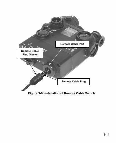
The Remote Cable Switch plugs into the back of the DBAL-I² for weapon mounted use as shown in Figure 3-6. Pressing the Remote Cable Switch activates the DBAL-I² in the operational mode and power level selected by the Activation Mode Selector Switch (e.g. A/L, D/L, A/H, etc). When the remote cable switch is released, the DBAL-I² turns off. In the Momentary Mode when the Remote Cable Switch has been double-clicked, the DBAL-I² will be activated in a constant ON mode for 5 minutes or until the Remote Cable Switch is pressed once again to return the unit to momentary activation. When the Remote Cable Switch is installed into the DBAL-I², it automatically locks in place. To remove it, pull back on the plug’s sleeve. DO NOT remove the Remote Cable Switch by pulling on the cable.
3-11
Figure 3-6 Installation of Remote Cable Switch
Remote Cable Plug Sleeve
Remote Cable Plug
Remote Cable Port

3-12
OPERATING INSTRUCTIONS, continued
3.2 DBAL-I² CONTROLS AND INDICATORS, continued 3.2.g IR ILLUM Focusing Knob
CAUTION Prior to submerging the DBAL-I² make sure the infrared illuminator focusing knob has been adjusted in a CCW direction to its stop. To prevent damage to the IR ILLUM Exit Port Cover, open the Exit Port Cover before turning the knob to adjust the focus.
NOTE Prior to exposing the DBAL-I² to extreme cold temperatures make sure that the IR ILLUM focusing knob has been adjusted to the focus point. In extreme cold temperatures the IR ILLUM focusing knob may offer more resistance. The IR ILLUM focus knob is marked with a white dot to use as a reference point. Direction of rotation and the corresponding beam size (spot to flood) is indicated on the DBAL-I² housing.
Turn the IR ILLUM CCW from the shooter’s perspective to mechanical stop, then CW to line up the white dots. This is optimal for a point or smallest diameter beam. Rotating the IR ILLUM CW adjusts the beam size from spot to flood, based on the range and size of the area to be illuminated.

3-13
Figure 3-7 The IR ILLUM Focusing Knob 3.2.h Optical Instrument Reticles (OIR) (Pattern Generators)
NOTE OIRs are not designed for accurate aiming of the weapon. Exit port covers are not intended for use over the Optical Instrument Reticles. When installing the OIR, the top loop is identified by an “ear” on one side.
If the OIR is installed in front of the IR ILLUM and the pattern appears blurry or is unrecognizable, focus the IR ILLUM to a point. To do this, turn the IR ILLUM CCW from the shooter’s perspective to mechanical stop, then CW to line up the white dots.
Focus Defocus
IR ILLUM Focusing Knob

3-14
OPERATING INSTRUCTIONS, continued
3.2 DBAL-I² CONTROLS AND INDICATORS, continued 3.2.h Optical Instrument Reticles (OIR) (Pattern Generators), continued The Optical Instrument Reticles (OIR), also called Pattern Generators, are used for command and control. When an OIR is installed in front of the IR ILLUM that has been focused to a spot, it will project the shape of a circle, triangle, plus sign, square, or T-shape as shown in Figure 3-8.
Figure 3-8 OIR, or Pattern Generator To use the OIR, select the appropriate pattern as marked on the front of the OIR. Remove the Exit Port cover, and replace it with the OIR. To remove the top Exit Port Cover, pull on the loose end of the Exit Port Cover retaining strap and stretch it over the top stud. Repeat the
Ear Top Loop
Bottom Loop
Pattern marked on
front

3-15
procedure to remove the bottom Exit Port Cover retaining strap from the DBAL-I². To install the OIR, stretch the end of the retaining strap over the retaining stud located on the bottom of the housing. Repeat the procedure by stretching the loose end of the retaining strap over the stud located on the top of the housing.
Figure 3-9 Installation of OIR, or Pattern Generator
3.2.i Adjusters
CAUTION
DO NOT over adjust the adjusters by forcing them beyond their end of travel.
NOTE Always move the adjusters slowly, once click at a time, to prevent the adjuster from jumping detents. In extreme cold temperatures the adjusters may offer more resistance.
Retaining Studs
Retaining Straps
OIR

3-16
The adjuster may offer resistance as you turn it in a CW direction from the factory neutral position. When the adjuster is harder to turn, it has reached the maximum CW travel. When the adjuster is at its maximum CW or CCW point of travel and turned in the opposite direction, the laser point may trace a small loop on the target. This is normal and does not indicate a failure condition. A positive load is required when zeroing the DBAL-I² to retain the set alignment. See paragraph 3.4. The adjuster knobs on the DBAL-I² may vary slightly in the force required to turn the adjusters. This is normal and does not indicate a failure condition. At the maximum CW or CCW travel the DBAL-I² lasers may not move a full 1cm per click at 25 m, or may jump squares on the target. If this happens the DBAL-I² should be returned to its factory neutral preset as described in Paragraph 3.5. DBAL-I² is for use on weapons where the MIL-STD-1913 rail is parallel with the bore of the weapon. In the factory neutral position the IR POINT should project on the same side of the target as the laser is mounted and must fall within 15 cm of the bore at 25 meters. See Paragraph 3.6.
The DBAL-I² is equipped with adjusters to zero the IR POINT and IR ILLUM. Each adjuster click will move the laser point by 1 cm at 25m.
OPERATING INSTRUCTIONS, continued 3.2 DBAL-I² CONTROLS AND INDICATORS, continued 3.2.i Adjusters, continued

3-17
The IR POINT adjuster guards are marked with arrows and the letters U/D and R/L, indicating the direction that the shot group will move if an adjuster is turned when the laser is mounted in the horizontal (top) position. The IR ILLUM adjuster guards are also marked with arrows and the letters U/D and L/R, indicating the direction that the ILLUM beam will move on the target if an adjuster is turned when the laser is mounted in the horizontal (top) position. The adjusters will move the IR POINT approximately 10” or 25 clicks in each direction from the factory neutral preset position at 25 meters. See Paragraph 3.5. Zero the IR POINT first then center the IR ILLUM on the IR POINT.
IR ILLUM Adjusters
Aiming Beam Adjusters Figure 3-10 Adjusters for
Illumination Beam Figure 3-11 Adjusters for Aiming
Beam
Figure 3-12 Adjuster Guard Markings

3-18
OPERATING INSTRUCTIONS, continued 3.2 DBAL-I² CONTROLS AND INDICATORS, continued 3.2.i Adjusters, continued
Aiming Laser Adjustment Table 3-2 indicates the direction of adjuster rotation and shot group movement for zeroing the IR POINT to the weapon when the DBAL-I² is TOP Mounted.
Figure 3-13 IR POINT Adjusters (Top Mounted)
Table 3-2 Adjuster Rotation and Shot Group Movement
for the Aiming Lasers (Top Mounted)
ZEROING THE AIMING LASER Adjuster Movement
Shot Group Movement
CW Up Top Adjuster Elevation (guard marked U/D) CCW Down
CW Right Side Adjuster Windage (guard marked R/L) CCW Left
When adjusting in a CCW direction, apply a positive load to the adjuster by turning an additional ¼ turn (12 clicks) CCW, then make the final adjustments by turning the adjusters in a CW direction. No positive load is required when adjustments are made in the CW direction.
Aiming Laser Adjusters

3-19
Figure 3-14 IR ILLUM Adjusters (Right Mounted)
IR ILLUM Adjustment Table 3-3 indicates the direction of adjuster rotation and resultant illumination beam movement for centering the illumination area on the aiming beam when the DBAL-I² is RIGHT mounted.
Table 3‐3 Adjuster Rotation and Illumination Area Movement for the IR ILLUM (Right Mounted)
ZEROING THE IR ILLUM Adjuster Movement
Shot Group Movement
CW Up Top Adjuster Elevation (guard marked U/D) CCW Down
CW Left Side Adjuster Windage (guard marked L/R) CCW Right When adjusting in a CCW direction, apply a positive load to the adjuster by turning an additional ¼ turn (8 clicks) CCW, then make the final zeroing adjustments by turning the adjusters in a CW direction. No positive load is required when adjustments are made in the CW direction.
IR ILLUM Adjusters

3-20
CHAPTER III SECTION II MOUNTING PROCEDURES
3.3 MOUNTING PROCEDURES
WARNING
Be sure the weapon is CLEAR and on SAFE before proceeding.
NOTE The DBAL-I² may be placed at any position (forward and aft) on the rail that is convenient for the operator. If the DBAL-I² is removed from the rail, the operator must take note of the position at which it was zeroed, and return it to the same position in order to ensure that zero is retained. Failure to fully tighten the Quick Release Mount will cause problems retaining the zero adjustment. Insure that the base of the Quick Release Mount is fully seated on the MIL-STD-1913 rail with NO front or rear overhang. The DBAL-I² is for use on weapons where the MIL-STD-1913 rail is parallel with the bore of the weapon. In the factory neutral position the IR POINT should project on the same side of the target as the laser is mounted and must fall within 15 cm of the bore at 25 meters. See Paragraph 3.5.
An integrated Quick Release Mount is used to attach the DBAL-I² to weapons equipped with a MIL-STD-1913 rail. Place the unit far enough back on the rail to allow for battery replacement without removal from the weapon. If removed, the DBAL-I² must be returned to the same position on the rail to retain zero.

3-21
Figure 3‐15 Quick Release Mount Configuration, Open
Figure 3-16 Quick Release Mount Configuration, Closed
Quick Release Mount Closed
Rail Clamp
Crossbar
Crossbar
Rail Clamp
Quick Release Mount Open

3-22
MOUNTING PROCEDURES, continued 3.3 MOUNTING PROCEDURES, continued 3.3.a M4/M16A4 Mounting Procedure
WARNING
Be sure the weapon is CLEAR and on SAFE before proceeding.
NOTE The DBAL-I² may be placed at any position (forward and aft) on the rail that is convenient for the operator. If the DBAL-I² is removed from the rail, the operator must take note of the position at which it was zeroed, and return it to the same position in order to ensure that zero is retained. Failure to fully close the Quick Release Mount will cause problems retaining the zero adjustment. The DBAL-I² is for use on weapons where the MIL-STD-1913 rail is parallel with the bore of the weapon. In the factory neutral position, the IR POINT should project on the same side of the target as the laser is mounted and must fall within 15 cm of the bore at 25 meters. See Paragraph 3.5.

3-23
Figure 3-17 DBAL-I² Top Mounted on M4/M16A
The DBAL-I² may be mounted on the TOP, LEFT, or RIGHT rail using the Quick Release Mount. Open the Quick Release Mount so that it is perpendicular to the DBAL-I² housing. See Figure 3-15. Align the crossbar on the bottom of the mount with a slot on the rail. Push forward on the DBAL-I² so that the crossbar contacts the front of the slot on the MIL-STD-1913 rail. Move the quick release arm so that
it is parallel with the body of the laser housing. See Figure 3-16. Install the Remote Cable Switch in a convenient location.

3-24
CHAPTER III SECTION III ZEROING PROCEDURES
This section provides zeroing instructions for the DBAL-I² using the MBS-1WE Laser Borelight System (LBS), LDI Part No. 3160635. 3.4 PLACING A POSITIVE LOAD ON THE ADJUSTERS
CAUTION
DO NOT over-adjust the adjusters by forcing them beyond their end of travel.
NOTE ALWAYS Zero starting with the Adjuster marked U/D. When moving the adjusters, make sure that the adjustment mechanism has engaged a detent and has not stopped between detents. Failure to properly engage a detent may impact accuracy as the laser may move when the weapon is fired.
Positive Load is required anytime an adjustment to IR POINT or IR ILLUM is made in a CCW direction. A Positive Load is not required when making a CW adjustment. Positive Load is the controlled compression of the spring within the adjuster mechanism to insure the highest level of accuracy is maintained after the weapon is zeroed. When adjusting in a CCW direction, apply a positive load to the adjuster by turning an additional ¼ turn (8 clicks) CCW, then make the final adjustment by turning the adjuster CW. For example, to move the adjuster one (1) click CCW, turn the adjuster CCW 8 clicks and then turn it CW 7 clicks to the new position.

3-25
3.5 FACTORY NEUTRAL PRESET
CAUTION
DO NOT over-adjust the adjusters by forcing them beyond their end of travel.
NOTE ALWAYS zero the DBAL-I² starting with the Adjuster marked U/D. When moving the adjusters, make sure that the adjustment mechanism had engaged a detent and has not stopped between detents. Failure to properly engage a detent may adversely impact accuracy as the laser may move to the next detent when the weapon is fired. The adjuster may offer some resistance as you turn it in a CW direction from the factory neutral position. When the adjuster is harder to turn, it has reached the maximum CW travel.
The DBAL-I² is preset at the factory to a neutral position. In the neutral position the laser beam is parallel to the bore of the weapon. The IR POINT can be returned to the factory alignment (neutral position) using the following procedure:
1. Turn the adjuster marked U/D CW to the natural stop.
2. Turn it CCW one and one-quarter turns (1 ¼) until the white dot on the adjuster aligns with the white dot on the adjuster guard.
3. Turn the adjuster marked R/L CW to the natural stop.
4. Turn it CCW one and three-quarter (1 ¾) turns until the white dot on the adjuster aligns with the white dot on the adjuster guard.

3-26
ZERIOING PROCEDURES, continued 3.5 FACTORY NEUTRAL PRESET, continued
Figure 3-18 Neutral Preset
Table 3‐4 Factory Neutral Preset
Adjuster Instruction
Adjuster Guard marked U/D for the IR POINT
Adjuster Guard marked R/L for the IR POINT
First, turn CW to end of travel. DO NOT force past mechanical stop. Next, turn CCW 1¼ turns. Finally, turn CW to align the dot on the adjuster with the dot on the adjuster guard.
Neutral Preset

3-27
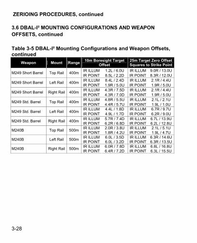
3.6 DBAL-I² MOUNTING CONFIGURATIONS AND WEAPON OFFSETS
NOTE
Offsets have been calculated using a specific barrel length, bullet weight, and rail adaptor. Offsets for differing combinations of equipment will require some adjustment.
Offssets have been calculated but have not been verified by live fire on a specific weapon. Always validate the offsets based on the specific weapon platform and cartridge.
Table 3-5 includes weapon type, mounting configurations and offsets used in conjunction with DBAL-I². The table includes the 10 Meter Laser Borelight Offsets as well as standard M16A2/M16A4 25 Meter Zeroing Target offsets. Table 3-5 DBAL-I² Mounting Configurations and Weapon Offsets
Weapon Mount Range 10m Boresight Target
Offset 25m Target Zero Offset Squares to Strike Point
IR ILLUM 2.1R / 2.9U IR ILLUM 2.1L / 0.0 M4 / M16A4 Top Rail 300m
IR POINT 1.9R / 3.0U IR POINT 1.9L / 0.0 IR ILLUM 5.0L / 1.2U IR ILLUM 5.0R / 2.0U
M4 / M16A4 Left Rail 300m IR POINT 5.1L / 1.1U IR POINT 4.6R / 1.8U IR ILLUM 4.4R / 3.6D IR ILLUM 5.0L / 7.0U
M4 / M16A4 Right Rail 300m IR POINT 4.5R / 3.3D IR POINT 4.6L / 6.5U IR ILLUM 2.2R / 3.7U IR ILLUM 2.1L / 0.0
M4 / M16 w / M203 Top Rail 300m IR POINT 2.0R / 3.9U IR POINT 1.9L / 0.0 IR ILLUM 4.3L / 0.8U IR ILLUM 4.8R / 3.0U
M4 / M16 w / M203 Left Rail 300m IR POINT 4.5L / 0.7U IR POINT 4.5L / 2.8U IR ILLUM 4.7R / 2.8D IR ILLUM 5.0R / 7.0U
M4 / M16 w / M203 Right Rail 300m IR POINT 4.8R / 2.4D IR POINT 4.6R / 6.5U
3-28
ZERIOING PROCEDURES, continued
3.6 DBAL-I² MOUNTING CONFIGURATIONS AND WEAPON OFFSETS, continued
Table 3-5 DBAL-I² Mounting Configurations and Weapon Offsets, continued
Weapon Mount Range 10m Boresight Target
Offset 25m Target Zero Offset Squares to Strike Point
IR ILLUM 1.2L / 6.0U IR ILLUM 9.0R / 13.0U M249 Short Barrel Top Rail 400m
IR POINT 8.5L / 2.2D IR POINT 8.3R / 12.0U IR ILLUM 8.4L / 2.4D IR ILLUM 2.1R / 4.4U
M249 Short Barrel Left Rail 400m IR POINT 1.9R / 5.0U IR POINT 1.9R / 5.0U IR ILLUM 4.3R / 7.5D IR ILLUM 2.1R / 4.4U
M249 Short Barrel Right Rail 400m IR POINT 4.3R / 7.0D IR POINT 1.9R / 5.0U IR ILLUM 4.8R / 5.5U IR ILLUM 2.1L / 2.1U
M249 Std. Barrel Top Rail 400m IR POINT 4.4R / 5.7U IR POINT 1.9L / 1.0U IR ILLUM 4.4L / 1.8D IR ILLUM 6.7R / 9.7U
M249 Std. Barrel Left Rail 400m IR POINT 4.9L / 1.7D IR POINT 6.2R / 9.0U IR ILLUM 5.7R / 7.4D IR ILLUM 6.7L / 13.9U
M249 Std. Barrel Right Rail 400m IR POINT 6.2R / 6.8D IR POINT 6.2L / 12.8U IR ILLUM 2.0R / 3.8U IR ILLUM 2.1L / 5.1U
M240B Top Rail 500m IR POINT 1.8R / 4.2U IR POINT 1.9L / 4.7U IR ILLUM 6.0L / 3.5D IR ILLUM 6.3R / 14.6U
M240B Left Rail 500m IR POINT 6.0L / 3.2D IR POINT 6.3R / 13.5U IR ILLUM 6.0R / 7.8D IR ILLUM 6.8L / 16.8U
M240B Right Rail 500m IR POINT 6.4R / 7.2D IR POINT 6.3L / 15.5U

3-29
3.6.a Boresight Using the Laser Borelight System (LBS)
WARNING
NEVER boresight in the High Power mode of operation.
CAUTION DO NOT over-adjust the adjusters by forcing them beyond their end of travel.
NOTE Always move the adjusters slowly, on click at a time, to prevent the adjuster from jumping detents. In extreme cold temperatures the adjusters may offer more resistance.

3-30
ZEROING PROCEDURES, continued
3.6 DBAL-I² MOUNTING CONFIGURATIONS AND WEAPON OFFSETS, continued
3.6.a Boresight Using the Laser Borelight System (LBS), continued
NOTE The adjuster may offer resistance as you turn it in a CW direction from the factory neutral position. When the adjuster is harder to turn, it has reached the maximum CW travel. When the adjuster is at its maximum CW or CCW point of travel and is turned in the opposite direction, the laser point may trace a small loop on the target. This is normal and does not indicate a failure condition. A positive load is required when zeroing the DBAL-I² for purposes of retaining the set alignment. See paragraph 3.4. The adjuster knobs on the DBAL-I² may vary slightly in the force required to turn the adjusters. This is normal and does not indicate a failure condition. At the maximum CW or CCW travel the DBAL-I² lasers may not move a full 1cm per click at 25 m, or may jump squares on the target. If this happens the DBAL-I² should be returned to its factory neutral preset as described in Paragraph 3.5. The DBAL-I² is for use on weapons where the MIL-STD-1913 rail is parallel with the bore of the weapon. In the factory neutral position the IR ILLUM / IR POINT should project on the same side of the target as the laser is mounted and must fall within 15 cm of the bore at 25 meters. See Paragraph 3.5.

3-31
This procedure is used to boresight the DBAL-I² on its weapon for a distance of 300, 400 or 500 meters using either the MBS-1WE LBS (LDI Part No. 3160635), or the MBS-AA LBS (LDI Part No. 3170635). Boresight Targets may be locally manufactured. Refer to the LBS Operator’s Manual for instructions on creating boresight targets. Each adjuster click moves the strike point 4mm on the 10 m boresight offset target. 1. Create the 10 Meter Boresight Target for the DBAL-I² weapon and
ammunition combination for which boresighting is required using the 10m Boresight Target Offsets in Table 3-5.
2. Position the target at 10 meters in a level, vertical position. Proper positioning of the target is critical for accurate boresighting results.
3. Stabilize the weapon so it does not move and insert the LBS Mandrel Interface assembly into the muzzle of the weapon.
4. Activate the LBS and verify that the LBS is properly aligned. Refer to LBS Operator’s Manual for zeroing procedures.
5. Adjust the target as required to place the laser dot on the target location marked “Laser Borelight.”
6. Activate the IR POINT by rotating the Activation Mode Selector Switch to the AIM LO (A/L) position. Adjust the Aiming Laser windage and elevation adjusters until the point is centered on the corresponding offset location.
7. A positive load is required on the adjustment mechanism when zeroing the DBAL-I² for purposes of retaining the set alignment. See Paragraph 3.4.
8. The DBAL-I² weapon combination is now boresighted. Rotate the DBAL-I² Activation Mode Selector Switch to OFF and remove the Borelight Mandrel Interface assembly from the weapon. Check the weapon barrel to make sure it is free and clear.
Repeat above steps to boresight the ILLUM beam.

3-32
ZEROING PROCEDURES, continued 3.6 DBAL-I² MOUNTING CONFIGURATIONS AND WEAPON OFFSETS, continued 3.6.a Boresight Using the Laser Borelight System (LBS), continued
Figure 3-14 Laser Borelight System 10m Zeroing Target

3-33
3.6.b Zeroing on a 25 Meter Range
CAUTION DO NOT over-adjust the adjusters by forcing them beyond their end of travel.
NOTE ALWAYS Zero the laser starting with the Adjuster marked U/D. Always move the adjusters slowly, on click at a time, to prevent the adjuster from jumping detents. In extreme cold temperatures the adjusters may offer more resistance. The adjuster may offer some resistance as you turn it in a CW direction from the factory neutral position. When the adjuster is harder to turn, it has reached the maximum CW travel. When the adjuster is at its maximum CW or CCW point of travel and is turned in the opposite direction, the laser point may trace a small loop on the target. This is normal and does not indicate a failure condition. The adjustment mechanism requires a positive load when zeroing the DBAL-I², for purposes of retaining the set alignment. See paragraph 3.4. The adjuster knobs on the DBAL-I² may vary slightly in the force required to turn the adjusters. This is normal and does not indicate a failure condition.

3-34
ZEROING PROCEDURES, continued 3.6 DBAL-I² MOUNTING CONFIGURATIONS AND WEAPON OFFSETS, continued 3.6.b Zeroing on a 25 Meter Range, continued
NOTE At the maximum CW or CCW travel the DBAL-I² lasers may not move a full 1cm per click, or may jump squares on the target. If this happens the DBAL-I² should be returned to its factory neutral preset as described in Paragraph 3.5. The DBAL-I² is for use on weapons where the MIL-STD-1913 rail is parallel with the bore of the weapon. In the factory neutral position the IR POINT should project on the same side of the target as the laser is mounted and must fall within 15 cm of the bore at 25 meters. See Paragraph 3.5.
This procedure is used to zero the DBAL-I² to the following weapons for the distances listed in Table 3-5. Refer to Table 3-2 and Table 3-3 for adjuster rotation and direction of shot group movement. Each adjuster click moves the strike point by approximately 1 cm on the M16A2/M16A4 25 meter zeroing target. 1. On a 25 meter zeroing target (Figure 3-20), mark the designated
strike point and designated 4 cm/6 cm strike zone based on the weapon you are using.
2. Mount the target on an “E” silhouette or other suitable surface at 25 meters.
3. Set the DBAL-I² adjusters to their factory neutral position as described in Paragraph 3.5.

3-35
4. Activate the IR POINT to be zeroed by rotating the Activation Mode Selector Switch to the desired position. Double-click the Integrated Momentary Activation Switch or the Remote Cable to activate the laser continuously. When aligning the IR POINT, leave the IR/ILLUM Exit Port Cover in place. Aim center mass of the target until the aiming laser disappears through the 3 cm cut out.
5. Fire a 3-round shot group and note the center of the shot group relative to the designated strike zone.
6. Adjust the aiming beam adjusters to move the center of the shot group to the designated strike zone.
7. Repeat steps 5 and 6 until the shot group falls within the strike zone.
8. When firing the M16, M4 series or M240 series of weapons, when 5
out of 6 consecutive rounds are in the designated 4 cm strike zone you are zeroed. When firing the M249 series of weapons, when 5 out of 12 non-consecutive rounds are within a 6 cm square, the weapon is zeroed.
Once the IR POINT is zeroed, open the Exit Port Cover in front of the IR ILLUM while aiming the weapon down range. If necessary, adjust the focus of the IR ILLUM so that it can be seen down range. Use the IR ILLUM adjusters to center the IR ILLUM on the IR POINT. Rotate the DBAL-I² Activation Mode Selector Switch to OFF.

3-36
ZEROING PROCEDURES, continued 3.6 DBAL-I² MOUNTING CONFIGURATIONS AND WEAPON OFFSETS, continued 3.6.b Zeroing on a 25 Meter Range, continued
Figure 3-15 Commercial 25m Zeroing Target

4-1
4 4
CHAPTER IV SECTION I OPERATOR PREVENTIVE MAINTENANCE CHECKS
4.1 GENERAL
WARNING
INVISIBLE LASER RADIATION AVOID DIRECT EXPOSURE TO THE BEAM
INFRARED LASER POINTER (Class IIIb) <50mW | WAVELENGTH: 835nm (±2.5nm)
INFRARED LASER POINTER/ILLUMINATOR (Class IIIb) <50mW or <200mW | WAVELENGTH: 835nm (±2.5nm)
• DO NOT stare into the laser beam. • DO NOT look into the laser beam through binoculars or telescopes. • DO NOT point the laser beam at mirror-like surfaces. • DO NOT shine the laser beam into other individual’s eyes.

4-2
OPERATOR PREVENTIVE MAINTENANCE CHECKS, continued
NOTE
Table 4-1 Preventive Maintenance Checks, has been provided so that you can keep your equipment in good operating condition. Perform functional tests in the order listed in Table 4-1. Operating Procedures are detailed in Chapter III, Section I. The Safety Screw must be installed in the Training Position. See Paragraph 3.2.c for Safety Screw operation. Functional testing of the DBAL-I² to ensure proper operation should be performed in a dark room or area away from light. Viewing of IR beams must be performed with a NVD, (AN/PVS-7 or AN/PVS-14).
4.1.a Warnings and Cautions Always observe the WARNINGS and CAUTIONS appearing in the table. 4.1.b Explanation of Table Entries 1. Item Number
Numbers in this column are for reference. Item numbers also appear in the order that you must perform the checks and services listed.
2. Interval This column tells you when you must do the procedure in the procedure column. BEFORE (B) PROCEDURES must be done before you operate or use the equipment. DURING (D) PROCEDURES must be done during the time you are operating or using the equipment. AFTER (A) PROCEDURES must be done immediately after you have operated or used the equipment.

4-3
3. Item to Check/Service This column provides the item to be checked or serviced.
4. Procedure This column gives the procedure you must do to check the item.
5. Not Fully Mission Capable If Information in this column tells you what faults will keep your equipment from being capable of performing its primary mission. Be sure to observe all special information and notes that appear in your table.

4-4
OPERATOR PREVENTIVE MAINTENANCE CHECKS, continued
Table 4-1 Preventive Maintenance Checks and Services Item No.
Interval Item to
Check/Service Procedure
Not Fully Mission Capable If:
1 B/D/A DBAL-I² Exterior -Check housing for separation between the
front and the rear section of the housing, missing screws
and missing switch knob, windage and elevation
adjuster.
A gap appears between the front and the rear section of the
housing, missing switch knob, or
adjuster.
WARNING: DO NOT STARE DIRECTLY INTO INFRARED LIGHT BEAM
2 B/A Exit Port Covers -Check for broken or missing covers, exit port
cover retention studs. -Move the Exit Port Covers
to the open position.
3 B/A Exit Port Lens -Check for cracked, dirty or broken lenses or missing
ILLUM focusing adjustment.
If cracked or missing lens or missing
ILLUM focusing knob.
4 B/A Adjusters -Check for broken, missing or stripped Adjusters.
Adjusters broken, missing or stripped or
laser fails to move.
5 B/D/A Quick Release Mount
-Check attachment to housing, broken, missing
parts. -Inspect rail clamp, crossbar and mount base for dirt and
corrosion. -If laser is loose on the rail: Move to a different position
on the rail; Move to a different rail on weapon;
Replace the rail on weapon.
Quick release mount loose, missing parts
or broken.
6 B/D/A Safety Screw -Broken or Missing Broken or Missing
7 B/D/A Remote Cable Port
-Check for mud or dirt and clean as needed.

4-5
Item No.
Interval Item to Check/Service
Procedure Not Fully Mission Capable If:
8 B/A Battery Compartment
-Check for corrosion, presence of O-ring, spring, battery cap lanyard. Inspect threads for dirt or damage.
Corroded or broken contacts.
9 B/A Battery Compartment
O-ring
-Check O-ring for cuts, cracks. –Lubricate with
silicone grease as needed.
10 B/A 3V CR123A Battery or 1.5V
AA Battery
-Install a known good battery
11 B/A Activation Mode Selector Switch and Integrated
Momentary Activation
Switch
-Select A/L (AIM LO) using the Activation Mode
Selector Switch. -Use the Integrated
Momentary Activation Switch and observe the beam spot on wall (NVD
necessary) -Select A/H (AIM HI) and
repeat the activation. -Repeat for each laser
activation position
Activation Mode Selector Switch
inoperative with the IR POINT or IR
ILLUM Beam Spot not visible
12 B Boresight Alignment
-Confirm that the IR POINT can be zeroed on the
weapon on which it will be mounted
-Check to make sure that the IR POINT projects on
the same side of the target as the laser is mounted and falls within 10.2 cm of the bore at 25 meters. See
Paragraph 3.5.
13 B/D/A LED Status Indicator
-Observe green LED is lit when lasing

4-6
OPERATOR PREVENTIVE MAINTENANCE CHECKS, continued
Table 4-1 Preventive Maintenance Checks and Services, continued
Item No.
Interval Item to
Check/Service Procedure
Not Fully Mission Capable If:
14 B/A Optical Instrument
Reticle
-Check for presence of cracks in the lens.
-Install and check pattern is visible using IR ILLUM.
-Focus IR ILLUM as needed to view pattern.
15 B/A Remote Cable Switch
-Insert the remote cable switch and activate the
laser.
16 B/A Flood Adjuster -Check that IR ILLUM adjusts from spot to flood
setting
17 B Exit Port Covers -Close exit port covers and press into place.
-Activate IR POINT and using NVD, check to make
sure no light is being emitted from around the
cover
18 A Textile Bag Check for torn fabric.
19 A Battery Remove battery

4-7
CHAPTER IV SECTION II OPERATOR TROUBLESHOOTING
4.2 GENERAL The purpose of troubleshooting is to identify the most frequent equipment malfunctions, probable causes, and corrective actions required. Table 4-2 lists the common malfunctions which may be found during the operation or maintenance of the DBAL-I² and accessory equipment. Perform the tests, inspections and corrective actions in the order listed. This manual cannot list all malfunctions that may occur; or all tests, inspections and corrective actions.
Table 4-2 Operator Troubleshooting
Malfunction Test / Inspection Corrective Action Ref.
Para.NOTE: DBAL-I² WILL NOT OPERATE IF THE ROTARY SWITCH IS NOT ALIGNED.
a. Ensure Activation Mode Selector Switch is in proper position
-Properly align switch 3.2.b
b. Verify Exit Port Cover is removed and that the Exit Port Lens is not
obscured by mud / dirt
-Remove Exit Port Covers
-Clean POINT & ILLUM Exit Port Lenses
4.3.b
c. Verify battery installation -Tighten battery cap -Install new battery
3.2.a
d. Inspect battery cap for damage or corrosion
-Notify Unit Maintenance -
e. Inspect battery contact spring in the battery compartment for damage
or corrosion.
-Notify Unit Maintenance -
1. POINT / ILLUM beams fail to come on
or stay on
f. Possible internal failure -Notify Unit Maintenance - a. Verify Exit Port Cover is removed
and that Exit Port Lens is not obscured by mud / dirt
-Remove Exit Port Cover -Clean POINT & ILLUM
Exit Port Lenses
4.3.b
b. Verify proper battery installation -Tighten battery cap -Install new battery
3.2.a
2. POINT / ILLUM beams have become weak (not as
bright)
c. Verify Exit Port Lens is not scratched or pitted
-Notify Unit Maintenance -

4-8
OPERATOR TROUBLESHOOTING, continued
Table 4-2 Operator Troubleshooting, continued
Malfunction Test / Inspection Corrective Action Ref.
Para.3. POINT /
ILLUM beams DO NOT move
Verify adjuster function -Clean as required -Notify Unit Maintenance
4.3.a
a. Verify Remote Cable Switch plug is fully seated
-Reconnect plug 3.2.f
b. Verify Remote Cable Port is free of mud / dirt
-Flush with water 4.3.g
c. Inspect Remote Cable Plug Contacts
-Clean as needed 4.3.g
4. Remote Cable Switch
inoperable, but Integrated Momentary Activation
Switch functions
d. Verify function of Remote Cable Switch
-Notify Unit Maintenance -
a. Verify Quick Release Mount is properly positioned/secured to
weapon
-Properly position and secure
3.3
b. If laser is loose on rail: -Move to different position on rail. -Move to different rail on weapon.
-Replace rail on weapon
-
c. Inspect mount base for corrosion or dirt
-Clean as required - Notify Unit Maintenance
4.3.a
d. Verify DBAL-I² is properly secured to Quick Release Mount
-Notify Unit Maintenance -
e. Verify Quick Release Mount is not damaged
-Notify Unit Maintenance -
5. POINT beam cannot be zeroed to weapon
f. Check for beam movement -Notify Unit Maintenance - 6. ILLUM knob turns, but beam
does not change
Verify knob is free of mud and dirt -Clean as required -Notify Unit Maintenance
4.3.a
7. OIR pattern is blurry or
unrecognizable
Verify IR ILLUM has been focused to a point
-Focus the IR ILLUM to a point
-Install different OIR -Notify Unit Maintenance
3.2.h

4-9
CHAPTER IV SECTION III OPERATOR MAINTENANCE
4.3 GENERAL
WARNING
DO NOT store the DBAL-I² with the battery installed.
CAUTION The use of gun cleaning agents that contain perchloroethylene or methylene chloride may permanently damage the DBAL-I² system.
The DBAL-I² is a rugged, compact laser device that is designed to operate in severe military environments. The exterior housing is made of aircraft grade aluminum and the outer components are made of chemically resistant materials that will not be harmed by chemicals normally encountered during military operations. Operator maintenance is limited to the inspection and cleaning of the DBAL-I² external surfaces, replacement of the battery before each mission, and removal of the battery after each mission. 4.3.a External Cleaning Clean the exterior of the DBAL-I² by flushing with water and wiping with a soft cloth. Such cleaning should be done whenever the DBAL-I² becomes dirty or after exposure to salt water. 4.3.b Exit Port Lens Cleaning To clean the POINT and ILLUM Exit Port Lenses, wipe clean using a soft cloth or disposable applicator dampened with water.

4-10
OPERATOR MAINTENANCE, continued
4.3.c Battery Compartment Before each use, inspect the battery and battery compartment for dirt, dust, or corrosion. If dirty, clean using a soft cloth or disposable applicator. 4.3.d Battery Cap Prior to water operations or immersion, inspect the O-ring seals in the battery cap to make sure they are free of sand or dirt particles. If the O-ring becomes cut, nicked or dried out, it should be replaced. If the battery cap is bent or scratched in the O-ring seating area, it should be replaced. 4.3.e IR ILLUM Prior to water operations or immersion, make sure that the IR ILLUM Focusing Knob has been tightened in a CCW direction so that it is seated on the housing. This will fully compress the internal O-rings to prevent the possibility of water infiltrating the housing. 4.3.f Battery Removal and Replacement Refer to Chapter III, Section I, Paragraph 3.2.a for Battery Installation procedures. No special tools or equipment are required to replace the battery. 4.3.g Remote Cable Port Before each use, inspect the remote cable port for dirt, dust, or corrosion. Thoroughly clean the receptacle by flushing with water, then wipe with a soft cloth or disposable applicator.

4-11
4.3.h Battery Compartment O-ring
NOTE Never use a sharp or metal object to remove O-rings, as they damage the O-ring or the O-ring groove contact surface.
Before each use, inspect the battery compartment O-ring for nicks, cuts or damage. Lubricate the O-ring as needed using silicone grease as follows:
1. Remove the O-ring. Be careful not to stretch the O-ring.
2. Check the O-ring for hair, sand, lint, or other debris and wipe clean as necessary. Be careful not to stretch the O-ring. If the O-ring is cut or cracked it must be removed and replaced with a new O-ring.
3. If possible, wash your hands prior to greasing the O-ring. Lubricate the O-ring using your fingertips and a small amount of silicone grease until there is a thin film covering the complete surface. DO NOT stretch the O-ring.
4. Before replacing the O-ring, visually inspect the groove in the battery compartment cap for hair, sand, lint, or other debris and wipe clean as necessary.
5. Install the O-ring in the groove at the base of the battery compartment cap, making sure that it is seated uniformly, with no twists or loose areas. Be careful not to stretch the O-ring.


5-1
5 5
CHAPTER V SECTION I UNIT TROUBLESHOOTING
WARNING
INVISIBLE LASER RADIATION AVOID DIRECT EXPOSURE TO THE BEAM
INFRARED LASER POINTER (Class IIIb) <50mW | WAVELENGTH: 835nm (±2.5nm)
INFRARED LASER POINTER/ILLUMINATOR (Class IIIb) <50mW or <200mW | WAVELENGTH: 835nm (±2.5nm)
• DO NOT stare into the laser beam. • DO NOT look into the laser beam through binoculars or telescopes. • DO NOT point the laser beam at mirror-like surfaces. • DO NOT shine the laser beam into other individual’s eyes.

5-2
UNIT TROUBLESHOOTING, continued 5.1 GENERAL Troubleshooting will identify equipment malfunctions, probable causes, and corrective actions. Table 5-1 lists common malfunctions that may occur. Perform the tests in the order they are listed.
Table 5-1 Unit Troubleshooting
Malfunction Test / Inspection Corrective Action Ref. Para.
a. Inspect battery compartment for corrosion
-Clean battery compartment
5.2.c
b. Inspect battery cap contact for corrosion
-Clean battery cap contact
5.2.d
c. Inspect battery cap and housing threads for contamination.
-Clean battery cap and housing threads
5.2.d
1. Beams fail to come on or stay on
d. Possible internal failure -Replace battery cap -Return for repair
5.7
a. Verify Exit Port Lens is not obscured by dirt
-Remove Exit Port Cover-Clean Exit Port Lenses
5.2.b
b. Verify battery installation -Tighten battery cap -Install new battery
3.2.a
2. Beams have become weak (not as bright)
c. Verify Exit Port Lens is not scratched or pitted
-Replace battery cap -Return for repair
5.7
3. Beams do not move Verify adjuster function -Clean as required -Return for repair
5.2.a 5.7
a. Inspect Remote Cable Port for dirt or debris
-Clean remote cable port 5.2.f
b. Inspect remote cable plug for damaged contacts
-Replace remote cable assembly
5.2.g
4. Remote Cable Switch inoperable, but the Integrated Momentary Activation Switch functions c. Possible remote cable
failure -Replace remote cable -Return for repair
5.2.g 5.7
5. Laser cannot be aligned, moves on rail, or when reset to factory neutral fails to project the IR POINT on the same side of the target as the laser is mounted.
Inspect weapon system rail. -Refer to appropriate weapons TM

5-3
CHAPTER V SECTION II UNIT MAINTENANCE
5.2 GENERAL
CAUTION
The use of gun cleaning agents that contain perchloroethylene or methylene chloride may permanently damage the DBAL-I² system.
Unit Maintenance Procedures consist of operational tests, inspections, troubleshooting and the replacement of a limited number of parts (paragraphs 5.2.a through 5.2.g). All authorized repair parts can be installed at the unit level. A DBAL-I² failing to meet the tests and inspections should be replaced. 5.2.a External Cleaning Clean the exterior of the DBAL-I² by flushing with water and wiping with a clean, soft cloth. Cleaning should be done whenever the DBAL-I² becomes dirty or after exposure to salt water. 5.2.b Exit Port Lens Cleaning Use a lens cleaning kit to clean the IR POINT and IR ILLUM lenses. 5.2.c Battery Compartment Before each use, inspect the battery and battery compartment for dirt, dust or corrosion. Clean the battery compartment by wiping with a soft, clean cloth. If a damp cloth is used to clean the battery compartment make sure to allow the compartment to air dry completely before reinstalling the battery cap.

5-4
UNIT MAINTENANCE, continued 5.4 REMOVAL AND REPLACEMENT OF PARTS, continued 5.2.d Battery Cap Prior to water operations or immersion, inspect the O-ring and the battery cap to make sure they are free of dirt, moisture or corrosion. Thoroughly clean the O-rings, battery cap and back of the battery compartment that seals against the O-ring using Isopropyl Alcohol. After cleaning, or if the O-ring becomes dried out, lubricate the O-ring using silicone grease. If the O-ring becomes cut or nicked, it should be replaced. 5.2.e Battery Compartment and Housing Threads Inspect threading on the battery cap and housing for contamination. If the threading appears to be oily or dirty, clean with Isopropyl Alcohol using a soft, clean cloth. 5.2.f Battery Removal and Replacement Refer to Chapter III, Paragraph 3.2.a for Battery Installation procedures. No special tools or equipment are required to replace the battery. 5.2.g Replace Remote Cable See Chapter III, Paragraph 3.2.f to replace the Remote Cable Switch. 5.3 TESTS AND INSPECTIONS See Preventive Maintenance Checks and Services Table 4-1. 5.4 REMOVAL AND REPLACEMENT OF PARTS Unit Maintenance is authorized for the removal and replacement of a limited number of assemblies. All repair parts can be installed at the unit level. Special tools or equipment are not required for maintaining the DBAL-I².

5-5
5.4.a Battery Removal and Installation See Chapter III, Paragraph 3.2.a for procedures.
5.4.b Remove and Replace Battery Cap To remove, stretch the end of the Retaining Strap over the stud on the Battery Cap. Unscrew the battery cap in a CCW direction. Install new battery cap and hand tighten in a CW direction. Reattached strap by stretching the end over the stud located on the battery cap. 5.4.c Removal and Replacement of Battery Cap Retaining Strap
NOTE Install the Battery Cap Retaining Strap below the Exit Port Cover Retaining Strap on the IR ILLUM. To remove the Battery Cap Retaining Strap it is necessary to remove the Exit Port Cover Retaining Strap first.
To install, stretch the end of the retaining strap over the stud located on the battery cap. Stretch the other end of the strap over the stud located below the IR ILLUM focusing assembly. To remove, stretch the end of the Strap over the stud on the Battery Cap then stretch the other end over the stud below the IR ILLUM. 5.4.d Remove and Replace Battery Cap O-ring
NOTE NEVER use a sharp or metal object to remove O-rings as they may damage the O-ring or the O-ring groove contact surface.Inspect the O-ring for nicks, cracks, cuts or abrasion. Also check to make sure that it feels soft. If damaged, replace the O-ring.

5-6
To remove pull the O-ring out of the groove at the base of the threaded portion of the battery cap and remove. Install the new O-ring by pulling it onto the battery cap so that it fits in the groove located at the base of the threaded portion of the battery cap. 5.4.e Remove and Replace Safety Screw
WARNING
In order to make the DBAL-I² operate in the High Power modes of operation the blue Safety Screw must be removed from the back of the unit. The Armorer will remove and store the Safety Screw.
CAUTION DO NOT over tighten the Safety Screw as it may strip the threads in the housing.
The Armorer will remove and store the Safety Screw using a 3/32 in.
hex key. The Armorer will install the Safety Screw using a 3/32 in. hex
key. 5.4.f Removal and Replacement of Exit Port Cover Retaining Straps To remove the top Exit Port Cover, pull on the loose end of the Exit Port Cover retaining strap and stretch it over the top stud. Repeat the procedure to remove the bottom Exit Port Cover retaining strap from the DBAL-I². To replace the Exit Port Cover Retaining Straps, stretch the end of the retaining strap over the retaining stud located on the bottom of the housing. Repeat the procedure by stretching the loose end of the retaining strap over the stud located on the top of the housing.

5-7
CHAPTER V SECTION III SERVICE/PACKING AND UNPACKING
5.5 Warranty Information Laser Devices, Inc. will furnish its standard form LIMITED WARRANTY in favor of its customers and the first end users of its products. The terms of the warranty are as follows: All LDI manufactured products (excluding flashlight bulbs, borelight inserts, batteries and other items that are ordinarily consumed during the normal use of the product) have a ONE (1) year limited warranty on parts and workmanship from the date of purchase. The warranty is void if the serial number or the manufacturer’s labels affixed to the product have been removed or if the product has been misused, modified, neglected or has been disassembled prior to return to the manufacturer. LDI will repair or replace defective products at its discretion. To the maximum extent permitted by law, LDI’s election to repair or replace the device shall constitute the purchaser’s sole remedy in the event of a defect. LDI disclaims all other warranties, expressed or implied, including but not limited to implied warranties of merchantability and fitness for a particular purpose. Moreover, to the maximum extent permitted by law, LDI on behalf of itself, its suppliers, distributors, dealers and agents disclaims any and all other liability for damages, including without limitation, actual damages, consequential damages and indirect damages, for personal injury, wrongful death, pecuniary loss and any other physical or financial loss arising out of the use or the inability to use any LDI product even if Laser Devices, Inc. has been advised of the possibility of such damages. This limited warranty gives the purchaser specific legal rights which may vary by state and jurisdiction. 5.6 Non-Warranty Information Non-warranty repairs are subject to an evaluation fee. DBAL-I² units that are not covered by the warranty will be tested and evaluated for failure. Customer permission and payment terms will be obtained prior to performing any repairs.

5-8
SERVICE/PACKING AND UNPACKING, continued
5.7 Return Instructions 5.7.a For service, repair or replacement: call 800-235-2162 (outside California) or 831-373-0701 (within California) and ask to speak with Service Representative (SR),or email [email protected]. 5.7.b To assist the SR with determining if the item is repairable, please provide the following information:
1. Serial Number of the defective item
2. Thorough description of the malfunction, defect or damage
3. An explanation as to how the malfunction, defect or damage occurred, if known.
If the SR determines that the item is under warranty or should be returned for repair, a Return Material Authorization (RMA) number will be provided. 5.7.c When returning the DBAL-I² for service or repair, the following procedures should be followed to prevent any additional damage:
1. Be sure that the DBAL-I² is free of all contaminants such as dirt or any other foreign material.
2. Remove the battery.
3. Place the Exit Port Covers over each of the lenses.
4. Place the DBAL-I² in the Shipping Case or Carrying Case if available. If the Shipping Case is not available, individually package each DBAL-I² unit being returned in a suitable container.
5.7.d Place the DBAL-I² and a copy of the test report or detailed description of the failure in a suitable packing/shipping container. Mark the package with the RMA number. Ship the fastest, traceable, prepaid means to Laser Devices, Inc., 70 Garden Court, Monterey, California 93940.
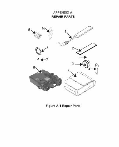
A APPENDIX A REPAIR PARTS
Figure A-1 Repair Parts

A‐2
REPAIR PARTS, continued
Table A-1 Repair Parts List (DBAL-I²) Item No.
Part No. Description QTY
1 FA05063-07 Remote Cable Switch, 7” 1 2 ITP-044 Loop Tape 1
3a FA06145 (AA Battery) Battery Cap 1 3b FA04533 (CR 123A Battery)
Battery Cap
4 FA6404 (AA Battery) F3693 (CR 123A Battery)
Strap, Battery Cap 1
5 A3186949 Bag, Textile 1
6 40072 / 50408 Assy, DBAL-I² 1 7 FC01223 Safety Screw, Hexagon Head 1 8 C02734 O-Ring 1 9 A05363-01 Assembly, Dust Cover, Clam 1
10 A05238-01 Assembly, 80 Deg Diffuser 1

A‐3
NOTES

A‐4
70 Garden Court • Monterey, CA 93940 Tel 831-373-0701 / 800-235-2162 (outside CA) Fax 831-373-0903 [email protected] • www.laserdevices.com
© 2009-2012 Laser Devices, Inc. PART NO. 100512