Embed Size (px)
Citation preview

TM 5-4310-378-14-—
TECHNICAL MANUAL
OPERATOR’S, UNIT, INTERMEDIATEEs=
DIRECT SUPPORT, ANDINTERMEDIATE GENERAL SUPPORT miiizll
MAINTENANCE MANUALFOR
- .
—
COMPRESSOR UNIT, RECIPROCATING,5 CFM 175 PSI, mm
GASOLINE ENGINE DRIVEN,HAND TRUCK MOUNTED
MODEL NUMBER ZPC175/5NSN 4310-01-190-0285
— .
HEADQUARTERS, DEPARTMENT OF THE ARMY1 JULY 1986


TM 5-4310-378-14C4
.-
,—
CHANGE
NO. 4
HEADQUARTERSDEPARTMENT OF THE ARMY
WASHINGTON, D.C., 30 APRIL 1993
Operator’s, Unit, Intermediate Direct support,and Intermediate General Support Maintenance Manual
forCOMPRESSOR UNIT, RECIPROCATING,
5 CFM 175 PSIGASOLINE ENGINE DRIVEN,
HAND TRUCK MOUNTEDMODEL NUMBER ZPC1’75/5NSN 4310-01-190-0285
DISTRIBUTION STATEMENT A: Approved for public release; c.istri.bution is unlimited.
TM 5-4310-378-14, 1 July 1986, is changed as fc~llows:
1. Remove and insert pages as indicated below. New or (hanged text material isindicated by a vertical bar in the margin. An illusl:raticln change is indicatedby a miniature pointing hand.
Remove pages Inse]”t pages
di and ii i an(l iiv 1-1 and 1-2 1-1 <md 1--2\2-13 and 2-14 2-13 and ;!-14..3-1 and 3-2 3-1 ;md 3--2“3-23 and 3-24 3-23 and 3-24‘43-37 and 3-38 3-37 and 3-38,4-5 and 4-6 4-5 ;md 4--6
2. Retain this sheet in front of manual for reference pllrposes.
By Order oftheSecretary oftheArmy:
Official:
44@??( wMILTON H. HAMILTON
AdministrativeAssistant totheSecretaryoftheArmy
040W
GORDONR.SULLIVANGenera/,Uni!edSta tesArmy
Chie!ofStaff
DISTRIBUTION:To be distributed in accordance with DA Form 12-25-E, “)lock no. 2437, require-ments for TM 5-4310-378-14.


. .CHANGE
NO. 3
TM 5431 0–378–14C3
HEADQUARTERSDEP/\RTMENT OF THE ARMY
WASHIN(iTON, D. C., 15 February1991
Operator’s, Unit, Intermediate Direct Support,and Intermediate General Support Maintenance Manual
for
COMPRESSOR UNIT, RECIPROCATINCi,5 CFM 175 PSI
GASOLINE ENGINE DRIVEN,HAND TRUCK MOUNTED
MODEL NUMBER ZPC1 75/5NSN 4310-01-190-0285
Approved for public release; distribution is unlimited
TM 54310–378–14, 1 July 1986, is changed as follows:
1. Remove and insert pages as indicated below. New or changelj text material is indicated by avertical bar in the margin. An illustration change is indicated by a mini~ture pointing hand.,-.
Remove pages Insert pages
2-5 and 2–62–1 3 and 2–143–1 through 3-43–7 and 3-83–1 5 through 3–183-37 and 3-383–47 through 3-503–67 and 3–68—-—
4–1 and 4–2———
4–1 7 and 4–185–7 and 5-8A-1/( A-2 blank)B-5 through B-8C-1 and C-2D-1 /( D-2 blank)E–1 and E–2Index 1 and Index 2
2–5 and 2–G2–1 3 and 2-143-1 through 3–4‘3_7 and 34
S-15 through 3–183-37 and 3-383-47 through 3–503-67 and 3--68:!–69/(3–70 blank)4-1 and 4—:!4-1 6.1/(4–1 6.2 blank)4-17 and 4--18!j–7 and 5–/]
,4-1/(A–2 blank)13–5 through B-8(~–l and C-.2D-1/( D-2 blank)E–1 and E-2Index 1 ancl Index 2
2. Retain this sheet in front of manual for reference purposes.

TM 5-4310-378-14C3
By Order of the Secretary of the Army:
CARL E. VUONOGtmeral, United States Army
Chief 0/Staff
Official:THOMAS F. SIKORA
Brigadier General, United States ArmyThe Adjutant General
DISTRIBUTION:To be distributed in accordance with DA Form 12–25E, (qty rqr block no. 2437)

- -
TM 5-4310-378-14C2
CHANGE
No. 2
HEADQUARTERSDEPARTMENT OF THE ARMY
WASHINGTON, D.C., 5 February 1990
Operator’s, Unit, IntermediateDirect Support, And
Intermediate General SupportMaintenance Manual
for
COMPRESSOR UNIT, RECIPROCATING,5 CFM 175 PSI
GASOLINE ENGINE DRIVEN,HAND TRUCK MOUNTED
MODEL NUMBER ZPC175/5NSN 4310-01-190-0285
Approved for public release. Distribution is unlimited.
TM 5-4310-378-14, 1 July 1986, is changed as follows:
1. Remove and insert pages as indicated below. New or changed text materialis indicated by a vertical bar in the margin. An illustration change is indicatedby a miniature pointing hand.
Remove pages Insert pages
1-1 through 1-82-1 through 2-62-9 through 2-123-1 and 3-23-7 and 3-83-143-15 through 3-183-21 and 3-224-9 through 4-165-3 and 5-45-7 and 5-8
1-1 through 1-82-1 through 2-62-9 through 2-123-1 and 3-23-7 and 3-83-143-15 through 3-183-21 and 3-224-9 through 4-165-3 and 5-45-7 and 5-8
2. Retain this sheet in front of manual for reference purposes.
TM 5-4310-378-14C2
By Order of the Secretary of the Army:
CARL E. VUONOGeneraL United States Army
Chief of Staff
Official:
WILLIAM J. MEEHAN, IIBrigadier Genera4 United States Army
The Adjutant General
DISTRIBUTION:To be distributed in accordance with DA Form 12-25A, Operator, Unit, Direct Support
and General Support Maintenance requirements for Compressor Unit, Reciprocal, ModelZPC 175/5.

CHANGE
No. I1
TM 5-4310-378-14c l
HEADQUARTERSDEPARTMENT OF THE ARMY
WASHINGTON, D.C., 16 September 1988
Operator’s, Unit, Intermediate Direct Support,and Intermediate General Support
Maintenance Manualfor
COMPRESSOR UNIT, RECIPROCATING, 5 CFM175 PSI, GASOLINE ENGINE DRIVEN, HAND TRUCK MOUNTED
MODEL NUMBER ZPC175/5NSN 4310-01-190-0285
TM 5-4310-378-14, 1 July 1986, is changed as follows:
1. Remove and insert pages as indicated below. New or changed text materialis indicated by a vertical ba~ in the margin. Anby a miniature pointing hand.
Remove pages
i and ii2-3 through 2-13/2-143-7 and 3-83-9 and 3-103-11 through 3-14A- l/A-2B-3 through B-8Index-1 through Index-3/Index-4
2. Retain this sheet in front of manual for
By orderoftheS ecretary oftheArmy:
official:
R.L.DILWORTH&igmfierGeneral, UnitedStatesA rmy
The Adjutant General
illustration change is indicated
Insert pages
i and ii2-3 through 2-163-7 and 3-83-93-14A-1/A-2B-3 through B-8Index-1 through Index-3/Index-4
reference purposes.
CARL E. WJONOGeneral, UnitedStatesArmg
ChiefofStat7
DISTRIBUTION:To be distributed in accordance with DA Form 12-25A, Operator, Unit, Direct Sup-
port and General Support Maintenance requirements for Compressor Unit, Reciprocal,Model ZPC 175/5 (TM 5-4310-378 Series).


.—.
TM 5-4310-378-14
WARNING PAGE
B
CARBON MONOXIDE
is produced by the internal combustion engine of this compressor.
DEATH
may result if personnel fail to observe safety precautions.
Carbon monoxide is a colorless, odorless, deadly poisonous gas which, whenbreathed, deprives the body of oxygen and causes suffocation. Exposure toair contaminated with carbon monoxide produces symptoms of headache,dizziness, loss of muscle control, or apparent drowsiness. Coma, permanentbrain damage, or death can result from severe exposure.
Carbon monoxide occurs in the exhaust fumes of internal combustion enginesand becomes dangerously concentrated under conditions of inadequateventilation. Observe the following safety precautions whenever the engine isrunning.
c Perform tests outdoors or in a well-ventilated area.
● Do not idle the engine for long periods without maintaining adequateventilation.
● Be alert at all times for exhaust odors and exposure symptoms.
● Be aware: the field protective mask for chemical-biological-radiological (CBR) protection will notmonoxide poisoning.
Expose victims to fresh air, keep warm, and doFor artificial respiration, refer to FM21-11.
protect you from ‘carbon
not permit physical exercise.

TM 5-4310-378-14
SEVERE BURNS
Illness, death, or injury may result if personnel fail toproperly. Observe the following safety precautions:
● Do not inhale vapor.
● Do not refuel a hot or running engine.
handle gasoline
● Do not refuel near open flame, sparks, or excessive heat.
● Be certain fuel lines and connections are secure.
● Do not overfill the fuel tank.
● Work in a well-ventilated area.
Allow an enginemaintenance.
and pump to cool before performing any service or
PERSONAL INJURY
may result if the engine cutoff switch is not pushed inmaintenance.
during service or
ELECTRICAL SHOCK
may result from performing maintenance while the engine is running. Theignition system of this engine contains dangerous voltages which can causesevere electrical shock.
HEALTH AND SAFETY HAZARD
Dry Cleaning Solvent(Stoddard Solvent)
P-D-680
e Combustible - do not use near open flames, near welding areas, or on hot surfaces.● Prolonged or repeated contact of skin with liquid can cause dermatitis. Repeated
inhalation of vapor can irritate nose and throat and can cause dizziness.6 If any liquid contacts skin or eyes, immediately flush affected area thoroughly with
water. Remove solvent-saturated clothing. If vapors cause dizziness, go to fresh air.● When handling liquid or when applying it in an air-exhausted, partially covered tank,
wear approved gloves.● When handling liquid or when applying it at an unexhausted, uncovered tank or
workbench, wear approved respirator, goggles, and gloves.
b

. . . ..
TM 5-4310-378-14
EYE INJURY
Compressed Air
● When using compressed air for any cleaning or drying operation, do not exceed 30 psigat the nozzle.
● Eyes can be permanently damaged by contact with liquid or large particles propelledby compressed air. Inhalation of air-blown particles or solvent vapor can damagelungs.
● When using air for drying or cleaning at an air-exhausted workbench, wear approvedgoggles or face shield.
● When using air for drying or cleaning at an unexhausted workbench, wear approvedrespirator and goggles.
c/(d blank)


TM 5-4310-378-14
TECHNICAL MANUAL
NO. 5-4310-378-14
HEADQUARTERSDEPARTMENT OF THE ARMY
WASHINGTON, D. C., 1 July 1986
Operator’s, Unit, Intermediate Direct Support,and Intermediate General Support
Maintenance Manual
for
COMPRESSOR UNIT, RECIPROCATING, 5 CFM175 PSI, GASOLINE ENGINE DRIVEN, HAND TRUCK MOUNTED
MODEL NUMBER ZPC175/5NSN 4310-01-190-0285
REPORTING ERRORS AND RECOMMENDING IMPROVEMENTS
You can help improve this manual. If you find any mistakes or if you know of a way to improve the procedures, pleaselet us know. Mail your letter, DA Form 2028 (Recommended Changes to Publications and Blank Forms), or DA Form2028–2 located in the back of this manual direct to: Commander, US Army Aviation and Troop Command, All_N:AMSAT-I-MTS, 4300 Goodfellow Blvd., St. Louis, MO 63120-1798. A reply will be furnished directly to you.
DISTRIBUTION STATEMENT A: Approved for public release; distribution is unlimited.
PageTABLE OF CONTENTS
CHAPTER 1. INTRODUCTION . . . . . . . . . . . . . . . . . . . . . . . . . . . . . . . . . . . . . . . . . . . . . . . . . . . . . . . . . . . . 1 –1
Section I. General Information . . . . . . . . . . . . . . . . . . . . . . . . . . . . . . . . . . . . . . . . . . . . . . . . . . . . . . . . l-lI Section Il. Equipment Description . . . . . . . . . . . . . . . . . . . . . . . . . . . . . . . . . . . . . . . . . . . . . . . . . . . . . . 1 –3
Section Ill. Technical Principles of Operation . . . . . . . . . . . . . . . . . . . . . . . . . . . . . . . . . . . . . . . . . . . . . 1 –7
CHAPTER 2. Operating lNSTRUCTIONS . . . . . . . . . . . . . . . . . . . . . . . . . . . . . . . . . . . . . . . . . . . . . . . . 2-1
Section I. Description and Use of Operator’s Controls and Indicators . . . . . . . . . . . . . . . . . . . . . . . 2-1ISection Il. Operator Preventive Maintenance Checks and Services (PMCS) . . . . . . . . . . . . . . . . . 2-4Section Ill. Operation Under Usual Conditions . . . . . . . . . . . . . . . . . . . . . . . . . . . . . . . . . . . . . . . . . . . 2+Section IV. Operation Under Unusual Conditions . . . . . . . . . . . . . . . . . . . . . . . . . . . . . . . . . . . . . . . . . 2-13
Change 4 i

——
TM 5-4310-378-14
TABLE OF CONTENTS (Continued)
Page
CHAPTER 3. UNIT MAINTENANCE INSTRUCTIONS.. . . . . . . . . . . . . . . . . . . . . . . . . . . . . . . . . . . . . . . 3-1
Section I. Lubrication Instructions . . . . . . . . . . . . . . . . . . . . . . . . . . . . . . . . . . . . . . . . . . . . . . . . . . . . . 3–1Section Il. Repair Parts, SpeciaITools, TMDE, and Support Equipment . . . . . . . . . . . . . . . . . . . . . 3–5Section lll. Service (Unusual) Upon Receipt of Equipment . . . . . . . . . . . . . . . . . . . . . . . . . . . . . . . . . 3-5Section IV. Unit Preventive Maintenance Checks and Services (PMCS) . . . . . . . . . . . . . . . . . . . . . 3-5Section V. Troubleshooting . . . . . . . . . . . . . . . . . . . . . . . . . . . . . . . . . . . . . . . . . . . . . . . . . . . . . . . . . . . . 3-14SectionVI. Maintenance Procedures ..,.... . . . . . . . . . . . . . . . . . . . . . . . . . . . . . . . . . . . . . . . . . . . . . 3-16Section VIl. Preparation for Storage or Shipment . . . . . . . . . . . . . . . . . . . . . . . . . . . . . . . . . . . . . . . . . . 3-68
CHAPTER4. INTERMEDIATE DIRECTSUPPORT . . . . . . . . . . . . . . . . . . . . . . . . . . . . . . . . . . . . . . . . . . 4–1MAINTENANCE INSTRUCTIONS
Sectionl. Troubleshooting . . . . . . . . . . . . . . . . . . . . . . . . . . . . . . . . . . . . . . . . . . . . . . . . . . . . . . . . . . . . 4–1Section Il. Maintenance Procedures . . . . . . . . . . . . . . . . . . . . . . . . . . . . . . . . . . . . . . . . . . . . . . . . . . . . 4-6
CHAPTER5. INTERMEDIATE GENERALSUPPORT . . . . . . . . . . . . . . . . . . . . . . . . . . . . . . . . . . . . . . . . 5-1MAINTENANCE INSTRUCTIONS
Sectionl. Troubleshooting . . . . . . . . . . . . . . . . . . . . . . . . . . . . . . . . . . . . . . . . . . . . . . . . . . . . . . . . . . . . 5–1Section Il. Maintenance Procedures . . . . . . . . . . . . . . . . . . . . . . . . . . . . . . . . . . . . . . . . . . . . . . . . . . . . 5–2
APPENDIXA. REFERENCES . . . . . . . . . . . . . . . . . . . . . . . . . . . . . . . . . . . . . . . . . . . . . . . . . . . . . . . . . . . . . . A-1
APPENDIXB. MAINTENANCE ALLOCATION CHART (MAC) . . . . . . . . . . . . . . . . . . . . . . . . . . . . . . . . . . B–1
APPENDIXC. COMPONENT OF END ITEM AND BASIC. ..... ..... .... . . . . . . . . . . . . . . . . . . C-1
APPENDIXD. ADDITIONAL AUTHORIZED LIST. . . . . . . . . . . . . . . . . . . . . . . . . . . . . . . . . . . . . . . . . . . . . D-1
APPENDIXE. EXPENDABLE SUPPLIES & MATERIALS LIST . . . . . . . . . . . . . . . . . . . . . . . . . . . . . . . . . E–1
GLOSSARY . . . . . . . . . . . . . . . . . . . . . . . . . . . . . . . . . . . . . . . . . . . . . . . . . . . . . . . . . . . . . . . . . . . . .. GLOSSARY-l
ALPHABETICAL INDEX . . . . . . . . . . . . . . . . . . . . . . . . . . . . . . . . . . . . . . . . . . . . . . . . . . . . . . . . . . . . . . . . . . . . . . INDEX-1
i i Change4
TM 5-4310-378-14
CHAPTER 1
INTRODUCTION
1Section 1. GENERAL INFORMATION
1-1, SCOPE
Type of Manual: Operator’s, Unit, Intermediate Direct Support, and Intermediate General Suppofl Maintenance
Model Number and Equipment Name: ZPC1 75/5 Reciprocating Compressor Unit, 5 cfm, 175 psi Gasoline EngineDriven.
Purpose of Equipment: Compresses Air
1-2. MAINTENANCE FORMS, RECORDS, AND REPORTS
Department of the Army forms and procedures used for equipment maintenance will be those prescribed by DA PAM738-750, The Army Maintenance Management System (TAMMS).
1-3. DESTRUCTION OF ARMY MATERIEL TO PREVENT ENEMY USE
Refer to TM 750-244-3, Procedures for Destruction of Equipment to Prevent Enemy Use.
1-4. PREPARATION FOR STORAGE AND SHIPMENT
Instructions for preparation for storage and shipment are in Chapter 3.
1-5. REPORTING EQUIPMENT IMPROVEMENT RECOMMENDATIONS (EIR)
If your air compressor needs improvements, let us know. Send us an EIR. You, the user are the only one who can tell uswhat you don’t like about your equipment, Let us know what you don’t like about the design or performance. Put it on anSF 368 (Quality Deficiency Report). Mail it to Commander, US Army Aviation and Troop Command, AlTN: AMSAT-I-MDO, ~4300 Goodfellow Blvd., St. Louis, MO 63120-1798. We’ll send you a reply.
1-6, WARRANTY INFORMATION
All components of the ZPC1 75/5 Reciprocating Compressor are warranted by Zwick Energy Research Organization fora period of 1 year. The warranty starts on the date of shipment as shown on the Material Inspection and Receiving Report(DD form 250), and Equipment Identification Plate.
Change 4 1-1

——-
TM 5-4310-378-14
1
1-2 Change 2

‘-
TM 5-4310-378-14
Section II. EQUIPMENT DESCRIPTION
1-7. PURPOSE OF AIR COMPRESSOR UNIT
Compresses air for inflating tires
1-8. CAPABILITIES AND FEATURES
● Handtruck mounted for portability
● Variable control of operating rate
● Engine cutoff switch for positive control
● Air cooled
1-9. LOCATION AND DESCRIPTION OF EXTERNAL COMPONENTS
1 AIR TANK. Steel tank that accumulates compressed air.
2 BELT GUARD. Protects operator, pulley, and flywheel.
3 ENGINE. Single cylinder, four-stroke, air cooled gasoline engine.
4 HAN DTRUCK. Welded steel frame with pneumatic tires.
5 COMPRESSOR. Two-stage, three-cylinder design.
6 AIR HOSE AND INFLATOR GAGE. Fifty-foot rubber hose. Inflator gage equippedwith regular and jumbo size air chucks.
1-3

— —.—
TN 5-4310-378-14
1-10. IDENTIFICATION
The compressor has two identification plates, as follows:
A. Operating Procedure Plate. The operating procedure plate is located on the fueltank.
123.4.56
7.8.9
10
11.12
1.2.
3.4.
II!2w-1CHECK ENGINE OIL LEVEL 1CHECK COMPRESSOR OIL LEVELCHECK FUEL LEVELTURN FUEL TANK VALVE ON 2OPEN FUEL TANK VENT VALVEPULL ENGINE CUTOFF SWITCH TO 3THE OUT POSITION.PLACE CHOKE TO ON POSITION 4RELEASE BELT TENSION IOLER.PULL STARTING ROPE SHARPLY 5UNTIL ENGINE STARTSALLOW ENGINE TO WARM THENMOVE CHOKE TO OFFsLOWLY ENGAGE IOLER.MOVE THROTTLE TO MAX POSITION 1
2Stop 3MOVE THROTTLE TO IOLE 4.
PUSH ENGINE CUTOFF SWITCHTO THE IN POSITIONCLOSE FUEL TANK VENT VALVET U R N F U E L T A N K VA L VE O F F
COLD WEATHEROPERATING PROCEDURES
MORAIN FuELTANKANDSEHVICEWITH FUEL IAW FE OSTOVVG 76CLASS BDRAIN ENGINE OIL AN LI SERVICEWITH 5W20W OIL IAw MI LL.46167OR AI N COMPRESSOR OIL AND SERVICEWITH ARCTIC OIL IAWMIL L46167FOLLOW ST EPS4-120F NORMALOPERATING PROCEDURESIF ENGINE FAIL ST OS TART SEErM54310378.13
LxxiMOVE THROTTLE TO IDLEPUSH ENGINE CUTOFF SWITCHTO THE IN POSITIONCLOSE FU E L T AN K VE N T V A L V E
TURN FUEL TAN KVALVE OFF
B. Identification Plate. Theidentification plate islocatedon the leftthe handle. It provides the compressor nomenclature, national stock number,engine serial numbers, contract number, weight, and dimension.
r .—
frame rail nearcompressor and
—10 PORTABLE AIR COMPRESSOR o 175 PSI 5CFM o
58328 /ZPC1000000 1 C O N T R N O . DAAJ1O.84-C-A161 ] W A R R A N T Y r] OR ~—~
“ R ~ CAPACITY 1 ‘ G A L 1 D A T E SHIPPEO [—1 D A T E I N S P ~—j
“ G ‘0 ~N E T W T 1~] LG ~]
NSN 4310-01.0285 ‘- mD A T E M F D [—1 H G T [;=] CUBAGE[~]
ENG=R~ s“’’w’~ MFD BY ZWICK ENERGY RESEARCH 1
0 U.S. PROPERTY o~ — .b& OOOO13d2
–-–l c)— — — . . .
1-4 Change .2

TM 5-4310-378-14
1-11. EQUIPMENT DATA—
I
A. Air CompressorManufacturer
Model NumberType
Unit
output (Maximum
Rated speedEngineCompressor
LengthWidthHeightWeight, netWeight, shipping
Capacities
rated speed)
Engine crankcaseCompressor crankcaseFuel tankAir receiver tank
B. EngineManufacturer
Model numberTypeHorsepowerCooling typeLubricating oilAir cleaner
c. CompressorManufacturerModel numberTypeCoolingLubricating oilAir cleaner
D. Spark plugGap
Zwick Energy ResearchHuntington Beach, CA
zPc175/5Two stage
5 cfm at 175 psig(0.14 m3/minute 12.3 kg/cm2)
3600 rpm60 strokes per minute
48 inches 0219 mm)24 inches (610 mm)26 inches (660 mm)148 pounds (67 kg)218 pounds (99 kg)
1-1/4 pints (0.6 litre)1-3/4 pints (0.8 litre)
2 gallons (7.6 litre)
Teledyne Wisconsin ‘Motor,Milwaukee, WI
W1-185Four cycle
4.6 (3.4 kW)Air
Per MIL-L-2104Oiled, wet
Curtis-Toledo, St. Louis ‘VIO.E23A
Three-cylinder, two-stageAir
Per MIL-L-2104Dry
MS35909-40.024 to 0.027 in. (0.6 to 0.7 mm)
—
1 -
1-5

k-
TM 5-4310-378-14
I
I
1-6 Change 2
.

!
TM 5-4310-378-14
- Section HL TECHNICAL P~CWL=OFOPERA~N
1-12. SECTION OVERVIEW
_ This section consists of a description of how the air compressor works. Paragraph 1-13describes the operation of the whole system. Paragraph 1-14 describes the operation of thecompressor.
1-13. AIR COMPRESSOR UNIT FUNCTION
1
2
3
4
5—
6
7
AIR DISCHARGE SYSTEM. Controls the discharge of air from the air receiver. A50-foot air hose, equipped with an inflator gage, is used to inflate tires and to readtire pressure.
AIR RECEIVER. Stores air compressed by the air compressor. It is equipped with agage to measure air pressure.
AIR COMPRESSOR. Compresses air in two stages to put out 5 cf m at 175 psig (O. 14m 3/minute at 12.3 kg/cm 3).
COMPRESSOR DRIVE. Transmits power from the engine to the air compressor bymeans of a pair of matched V-belts. A belt guard protects the operator from injuryand the engine pulley and compressor flywheel from damage.
GASOLINE ENGINE. Provides 4.6 horsepower (3. 4 kW) to run the compressor.
HANDTRUCK ASSEMBLY. Gives the air compressortwo pneumatic rubber tires to provide a soft ride.
BELT TENSION IDLER. Allows the compressor to beengine.
mobility. It is equipped with
disengaged during starting of
I
I
I
i––.
i.Change 2 1-7

TM 5-431O-378-14
1-14. AIR COMPRESSOIL Thepicture below shows thegeneral operation of the air compressor.The air compressor has two low pressure cylinders which both feed into the high pressurecylinder. Only one low pressure cylinder is shown here.
The compression cycle starts with the low pressure pistons (1) at the top of stroke.
When the pistons move down, they draw air through the air filters (2) and inlet valve (3) into thecylinders. The air filters keep dirt out of the compressor.
On the upstroke, inlet valve (3) closes and the pistons (1) push air out into the intercooler (5)through the exhaust valve (4).
Compressing the air heats it up. The intercooler (5) gets rid of some of that heat before passingthe air on to the high pressure stage.
The high pressure stage works the same EM the 10 w pressure stage except that the high pressurepiston goes up when the low pressure pistons go down. This way, the low pressure pistons aredrawing air in while the high pressure is pushing air out.
Compressed air from the high pressure stage goes to the air tank through a connecting tube.
AIRINLET
h 1~
-TO AIR TANK
I 6
1-8
.

r
TM 5-4310-378-14
CHAPTER2
OPERATING INSTRUC~ONS
Section I. DESCWPTION AND USE OF OPERATOR'S CONTROLS AND INDICATORS—
2-1. GENERAL.
Table 2-1 will show you the controls and indicators you will need to operate the air compressorunit.
Table 2-1. Compressor Assembly Controls and Indicator
CONTROL ORKEY INDICATOR FUNCTION
1 Choke lever Aids in starting a cold engine by enriching thefuel mixture.
2 Speed control lever Controls engine speed. Rotating lever fully
3 Fuel cock
4 Engine drain plug
5 Dipstick
6 Grease fitting
7 Fuel filler
I _
8 Ignition switch
!––.
1.
9 Recoil starter
10 Compressor drain
counterclockwise is high speed and fully clock-wise is low speed.
Controls fuel flow. Vertical position is fuel ONand horizontal position is fuel OFF.
Allows engine crankcase to be drained for periodicoil changes.
Measures oil in engine crankcase. Safe engineoperating level is indicated between upper andlower level marks on dipstick.
Grease fitting for wheel. One is installed on theinside of each wheel.
Provides opening for filling gas tank. A strainerinside the opening ensures clean fuel. The fueltank is translucent so the fuel level is visible.A fuel tank vent is located in the filler cap toallow fuel tank pressure to equalize. When the ventis rotated fully clockwise, it is closed.
Labeled TO STOP PUSH IN, this switch must be pulledout to start the engine. When any maintenance is beingperformed on the compressor assembly, this switchmust be pushed in to prevent the equipment fromstarting up.
Starts engine when rope is pulled.
plug Allows compressor crankcase to be drained forperiodic oil changes.
2-1

1?——.———.———— . .-—
TM 5-4310-378-14
Table 2-1. Compressor Assembly Controls and Indicator (Continued)
CONTROL ORKEY INDICATOR FUNCTION
11
12
13
14
15
16
17
18
19
20
‘1 21
Oil level sight gage
Oil filler/breathercap
Unloader valves
Interstage reliefvalve
Air tank drain valve
Pilot valve
Inflator gage
Air tank relief valve
Pressure gage
Dual foot air chucks
Belt tension idler
Indicates level of oil in compressor crankcase.
Keeps dirt out of the oil filler and relieves pressurebuildup in compressor crankcase.
Located in each cylinder head on the compressor,these valves vent excess pressure to the atmosphere.
Relieves excess interstage pressure.
Drains moisture from air tank. Manually operated.
Senses tank pressure and at 180 psi signals comp-ressor cylinder unloader valves to vent compressorto atmosphere.
Indicates air pressure in system being pressurized.
Releases compressed air in excess of compressor safetylimits. A pull ring is provided to check operation.
Indicates air pressure available for use.
Used to inflate tires. Two different sizes providedto accommodate different sized tire valves.
Used to disengage V-belts from engine to compressorduring starting.
I
i
2-2 Change z
.

4 —. . . ..— .
TM 5-4310-378-14
.—
—
—
I
Change 2 2-3
,
TM 5-4310-378-14
SECTION II. OPERATOR’S PREVENTIVE MAINTENANCECHECKS AND SERVICES (PMCS)
2-2. GENERAL. The operators PMCS table lists the inspections and service procedures to properly maintainthe air compressor in good operating condition. Items covered here are appropriate for operator level only. Alwayskeep in mind the CAUTIONS and WARNINGS before performing checks and services listed in the PMCS table.
2-3. PMCS TABLE FORMAT. The following columns makeup the PMCS table.
a. ltern No. Each maintenance check is identified by a separate item number. The item column will be usedas a source of item numbers for the “TM Number” column on DA Form 2404 Equipment Inspection andMaintenance Worksheet, in recording results of PMCS.
b. lnterva~ The interval column of the PMCS table identifies when to perform the service check or maintenance.A dot (*) appears underneath the appropriate column(s) abbreviation:
B —Before OperationD —During OperationA —After Operationw–weeklyM–MonthlyQ –Quarterly
C. Item To Be InspectecVPmcedure. This column identifies how to perform the required checks and services.Carefully follow these instructions, If appropriate tools are not available to operator, organizational maintenanceshould perform the work. If your equipment does not perform as required, refer to Chapter 3, Section V.Troubleshooting for possible problems. Report any malfunctions or failures to organizational maintenance.
d. Equipment Not Ready/Available Ifl This column indicates when and why equipment cannot be used aftercompleting the specific PMCS.
mThe terms ready/auaihble and mission capable refer to the same status: Equipment is on
/hand and is able to perform its combat missions (see DA PAM 738-750).
2-4. SPECIAL INSTRUCTIONS.
a. If the equipment must be kept in continuous operation, check and service only those items that can be check-ed and serviced without disturbing operation. Make the complete checks and services when the equipment canbe shut down.
b. “Before operation (B)” checks should be limited to those required for consecutive application by an assignedoperator. Perform ‘Weekly (W)” as well as “Before Operation (B)” PMCS if:
(1) Compresso~ has not been operated since the last weekly PMCS, or;
(2) Compressor is being operated for the first time.
c. Leakage definitions for operator PMCS are classified as follows:
Class I Seepage of fluid (as indicated by wetness or discoloration) not great enough to form drops.
Class II Leakage of fluid great enough to form drops but not enough to cause drops to drip from item beingchecked/inspected.
Class 111 Leakage of fluid great enough to form drops that fall from the item being checked/inspected.
EIEElEquipment operation is allowable with minor leakages (Class I or II). Consider the fluidcapacity in the item system being checked/inspected. When in doubt, notify your supervisor.
When operating with Class I or Class 11 leaks, continue to check fluid levels as requiredby PMCS table.
Class III leaks should be reported to your supervisor.. 2-4 Change 1

— —V’
TM 5-4310-378-14
—. Table 2-2. Operator Preventive Maintenance Checks and Services
B - Before D - During A - After W’ - Weekly M - Monthly Q - Quarterly
ITEM.NO.
1
2
3
4
5
6
7
.
7.11-
INTERVALi
D
D
B
●
w
m
8
j
8
D
8
L
I
1
i
I
ITEM TO BE INSPECTEDPROCEDURE:
Engine Recoil Starter. Inspect for completeness andsecure mounting. Inspect for signs of wear.
Belt Guard Assembly. Inspect for damage and securemounting.
Engine. Inspect for secure mounting, Inspect foroverheating.
Fuel Tank and Fuel Filter. Inspect for fuel level andsediment in fuel filter bowl.
Cooling System Ducts, Covers, and Deflectors.Inspect for secure mounting. Inspect for overheating.
Flexible Hoses and Rigid Tubing. Inspect for dam-age, loose connections, and air leakage.
Compressor Oil Sight Glass. Be sure that oil level isin center of sight gage (1). If oil is low, remove oilbreather cap (2) and add oil (Appendix E, Item 5) tobreather cap opening (3) until oil level is at center ofsight gage (1).
Frame Assembly. Inspect for sprung frame members,cracks in welds, loose mounting hardware for beltidler.
EQUIPMENT IS NOTREADY/AVAILABLE IF:
Any signs of damage.
Any signs of damage, loosemounting, or missing hard-ware.
Loose mounting or over-heating.
Overheating.
Cracked and/or leaking.
Oil level is low.
Frame bent; welds broken;idler mountings loose or bro-ken.
Change 3 2-5.

———— .—— —____e
TM 5-4310-378-14
Table 2-2. Operator Preventive Maintenance Checks and Services (Continued)
B—Before D–During A—After W–Weekly M–Monthly Q–Quarterly
[’1’EMNo.
8
9
INTERVAL ITEM TO BE INSPECTEDPROCEDURE:
Engine Oil Dipstick. Check that oil level is betweenLOWER LEVEL and UPPER LEVEL on dipstick.LJnscrew dipstick (1) from engine crankcase. Wipe]ff dipstick with clean rag and insert all the way in-;O the crankcase. Do not thread in place to checkil level. If oil is low, add oil (Appendix E, item 5);hrough dipstick opening (2). Screw dipstick ininger tight.
I)rain Valve. Open the drain cock (1) and allow all:ondensed moisture to drain off, Close the drainmlve.
EQUIPMENT IS NOTREADY/AVAILABLE IF:
Ul level is low, or dipstick ismissing.
Leaking or missing.
.2-6 Change 1

P —...———
TM 5-4310-378-14
Table 2-2. Operator Preventive Maintenance Checks and Services (Continued)
B—Before D—During A—After W–Weekly M–Monthly Q–Quarterly
TENNo.
10
11
[NTERT L ITEM TO BE INSPECTEDPROCEDURE
;ompressor Au Cleaners. Clean the air cleaners asollows: Remove wing nut (1), washer (2), and cover3). Remove filter (4) and screen (5). Clean filter (4)md screen (5) in a solution of mild soap and water.h-me thoroughly and allow to dry. Wipe the cover3) and body (6) clean with a clean cloth. Install~creen (5), filter (4), cover (3), washer (2), and wingmt (l).
6
Engine Air Cleaner. Take off cover (1) by pullingrlown and outward at clip (2). Remove element (3)md retainer (4). Wipe all metal parts clean andwash element in a solution of mild soap and water.Wrap element in clean toweling and squeeze dry.Soak element in kerosene (Appendix E, item 8),then squeeze out excess kerosene. Install retainer[4) and element (3) then cover (l). Make certain clip(2) is engaged.
EQUIPMENT IS NOTREADY/AVAILABLE IF:
Change 1 2-7

I
I
TM 5-4310-378-14
Table 2-2. Operator Preventive Maintenance Checks and Services (Continued)
B—Before D–During A—After W–Weekly M–Monthly Q–Quarterly
la-i[TEM INTERVAL ITEM TO BE INSPECTED EQUIPMENT IS NOT
‘O. B D AW Q PROCEDURE READY/AVAILABLE IF:
12
13
.5. ASSEMBLY AND PREPARATION FOR USE
a. This compressor comes fully assembled and is ready for use after draining preservation oil in the engine,hecking oil in the compressor, and filling the fuel tank. Refill engine crankcase and add to compressor crankcase
oil (Appendix E, item 5), as necessary.
b. Instructions for use are for information and guidance of personnel responsible for operation of the com-pressor assembly.
● Air Compressor Assembly. Clean the complete aircompressor (external) with a solution of mild soapand water. Rinse thoroughly and allow to dry.
● Air Tank Relief Valve, Pull the ring on the pressure Pressure valve does notrelief valve with the compressor running. The valve allow air to escape.should allow air to escape.
Section III. OPERATION UNDER USUAL CONDITIONS
C. The operator must know how to perform every operation of which the compressor assembly is capable.The following paragraphs contain instructions on starting and stopping the compressor assembly, on operationof the compressor assembly, and on coordinating the basic motions to perform the specific tasks for which theequipment is designed.
2-6. INITIAL ADJUSTMENTS
Inspect compressor assembly and engine for loose or missing hardware, corrosion, or obvious damage. Reportany problems to your supervisor.
2-7. OPERATING PROCEDURE
a. Selection and Preparation of Compressor Site.
(1) Locate the compressor on a level surface as close to the tires to be inflated as possible.
.2-8 Change 1

TM 5-4310-378-14
_ 2-5. STARTING
a. Check oil level in:
(1) The engine. Engine oil dipstick (l).
(2) The compressor. Compressor oil level sight glass (2).
Fill as required.
—
(--l
Change 2 2-9
.

TM 5-4310-378-14
2-8 STARTING (cont.)
I.xw!xJSevere burns, illness, or death may result if personnel fail to han-dle gasoline properly. Observe the following precautions:
. Do not inhale vapor.
. Do not refuel a hot or running engine.
s Do not refuel near open flame, sparks, or excessive heat,
. Be certain fuel lines and connections are secure.
● Do not overfill fuel tank.
. Work in a well-ventilated area.
1===1
Q Serious hearing loss or deafness could occur if this equipmentis operated without professionally-fitted ear protection f oroperating and maintaining personnel. The noise level for thisequipment exceeds the allowable limits for unprotected person-nel. Unprotected/unnecessary personnel must be kept out of theimmediate area.
I WARNING I
● Do not use this compressor for charging cylinders that requirebreathable air.
I b. Fill fuel tank. Fuel tank filler (3).
c. Open the drain valve and allow all pressure to drain from air receiver tank. Close drain valve.
I
.
2-10 Change 1

I
I
r
TM 5-4310-378-14
— 2-8. STARTING (cont.)
d. lhm fuel cock ON (turn to vertical position).
~1
e.
f.
—
Do not open fuel tank vent more than two turns to avoid 10SS ofscrew.
Open fuel tank vent in fuel tank cap (rotate two turns counterclockwise).
Prime fuel system if engine is new or seldom used.
(1) Push ignition switch (1) IN.
(2) Close choke.
(3) Rele=e belt tension idler.
(4) Pull starting rope (2).
(5) Allow starting rope to retract.
(6) Pull starting rope again.
(7) Allow to retract.
g. Pull ignition switch out. Set speed control at mid position.
h.
i.
j=
k.
1.
m.
Pull starting rope sharply.
Allow to retract.
When engine starts, gradually open choke and move speed control to m ax position.
Repeat steps e. and f., if necessary, until engine starts. (Cold engines are harder to start.)
Slowly engage belt tension idler.
If engine does not start after several attempts, see TROUBLESHOOTING procedures inChapter 3 of this manual.
Change 2 2-11

TM 5-4310378-14
2-9. OPERATION
Chetx pressure gage reading. It should read between 140 and 175 psi (9.8 and 12.3 kg/cm’).
As soon as the engine is runnin g) the compressor is ready to operate and inflate tires. If the compressor doesnot operate, see TROUBLESHOOTING procedures in Chapter 3 of this manual. Watch for any unusual noiseor vibration.
2-10. STOPPING
a. Set speed control lever to idle.
b. Push ignition switch (1) in (STOP)
c. Close fuel tank vent valve.
d. Turn fuel tank valve OFF.
2-11. PREPARATION FOR MOVEMENT
Stop the engine. Close fuel vent valve on fuel cap.
2-12.
I
a.
I
b.
c.
. 2-12
MOVEMENT TO A NEW WORK SITE
I C A U T I O N I
The wheels and axle of the compressor assembly are designedto move the compressor assembly into position at the worksite.They are not designed for use during road or highway movementof the compressor assembly.
Use a shipping dock or use wood planks as aramp to load the compressor assembly on thebed of a suitable truck to transport the com- !/7? ~presser assembly.
Grasp the handlespressor assembly.
(1) when moving the com-
Secure the compressor assembly to the side ofthe truck to prevent it from shifting.
\ \
Change 1

* . — .
TM 5-4310-378-14
—
Section IV. OPERATION UNDER UNUSUAL CONDITIONS
2-13. OPERATION IN EXTREME COLD
a.
b.
c.
d.
e.
f.
I
Keep entire unit free of ice and snow.
Cover unit when not in use.
Shelter unit from weather, if possible.
Use proper engine oil for cold weather operation (Appen-dix E, item 7).
Keep fuel tank full to prevent moisture condensation, whichcan freeze. Use FEPSTPW-G-76 Class B gasoline.
Ar--‘ 4!s3---,
f!iiil- 2
Check and clean fuel strainer before and after operating to prevent an accumulation of moisture, which canfreeze.
(1) Turn fuel cock lever (1) to OFF.
(2) Unscrew bowl (2), remove gasket (3) and screen (4) from strainer assembly,
(3) Clean parts with water and dry thoroughly.
(4) Reassemble strainer assembly.
(5) If unit is going into storage, leave fuel cock lever closed.
Drain air tank after use to prevent moisture in tank from freezing.
(1) Open tank drain valve, leave open until air no longer hisses.
(2) When tank is no longer pressurized, close tank drain valve.
NOTEIf the engine resists starting and the temperature is below O“F (–18”C), perform stepsin paragraph 2-13 to start a cold engine.
Change 4 2-13
TM 5-4310-378-14
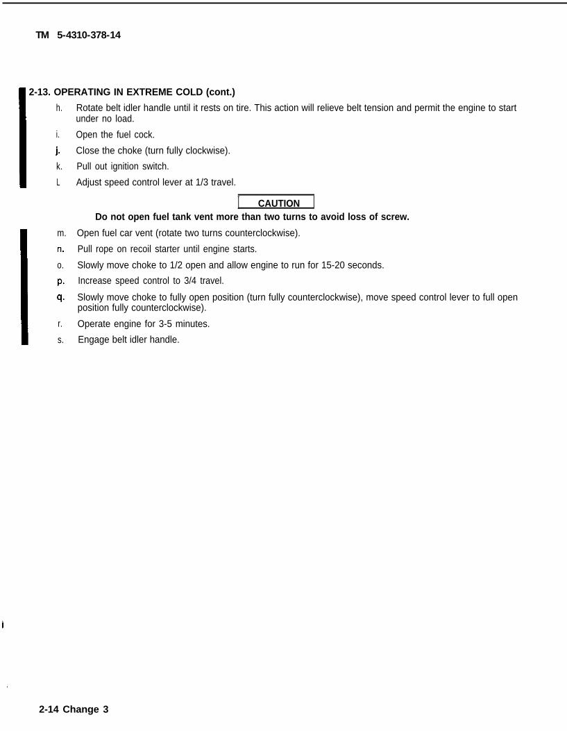
~ 2-13. OPERATING IN EXTREME COLD (cont.)
h.
i.
j.k.
L
m.
n.
o.
P.
q.
r.
s.
Rotate belt idler handle until it rests on tire. This action will relieve belt tension and permit the engine to startunder no load.
Open the fuel cock.
Close the choke (turn fully clockwise).
Pull out ignition switch.
Adjust speed control lever at 1/3 travel.
I CAUTION IDo not open fuel tank vent more than two turns to avoid loss of screw.
Open fuel car vent (rotate two turns counterclockwise).
Pull rope on recoil starter until engine starts.
Slowly move choke to 1/2 open and allow engine to run for 15-20 seconds.
Increase speed control to 3/4 travel.
Slowly move choke to fully open position (turn fully counterclockwise), move speed control lever to full openposition fully counterclockwise).
Operate engine for 3-5 minutes.
Engage belt idler handle.
.
2-14 Change 3

$ “ - - — . . . — — - . , - — . . — _ _ _
TM 5-4310-378-14
2-14. OPERATION IN EXTREME HEAT I—
a. If possible, protect the compressor assembly from direct rays of the sun.
b. Allow adequate space for ventilation. If the compressor is operated in an enclosure, use a fan to cir-culate air.
c. Keep the engine shrouding and compressor clean to provide proper heat transfer to the air.
d. Check drive belt for tension frequently. Improper drive belt tension often results in overheating.
e. Check that lubricants in the engine comply with Appendix E, item 5.
2-15. OPERATION IN HIGH ALTITUDES I
The operating efficiency of both engine and compressor diminishes at higher altitudes. Make sure that theengine is operating at peak efficiency to provide the highest possible compressor output.
2-16. OPERATION IN SANDY OR DUSTY AREAS I
a. When the compressor is operated under sandy or dusty conditions, service engine and compressor aircleaners frequently.
b. While filling the fuel tank, take care to prevent sand and dust from entering the fuel system.
c. Check fuel strainer bowl for accumulations of. dirt.
(1)
(2)
I
(3)
(4)
Turn fuel cock lever (1) to OFF. h
o
~>
Unscrew bowl (2), remove gasket (3), andscreen (4) from strainer assembly. Discard A
/ “gasket.Q
Clean parts with water and dry thoroughly. @.%
Reassemble strainer assembly. Use newgasket.
If unit is going into storage, leave fuel cock(5)I lever closed.
‘--4d. Protect unit with tarpaulin when not in use.
0=
fii3-02
Change 1 2-15

i-
TM 5-4310-37&14
~ 2-17.
a.
b.
12-18,
a.
b.
OPERATION UNDER RAINY OR HUMID CONDITIONS
Fill the fuel tank immediately after every operating period to prevent moisture in the air from condens-ing and entering the fuel system. Check the fuel strainer bowl frequently for collection of moisture.
Take special care to prevent rust and corrosion of exposed metal surfaces.
OPERATION IN SALT WATER AREAS
Salt water causes corrosion. Use fresh water to wash off any salt water that comes in contact with the equip-ment. Avoid using excess water around air cleaners, fuel tank vent, and electrical system. This will helpprevent the formation of rust and corrosion.
Take special care to prevent rust and corrosion of exposed metal surfaces.
.2-16 Change 1

TM 5-4310-378-14
CHAPTER 3
UNIT MAINTENANCE INSTRUCTIONS
Section l. LUBRICATION INSTRUCTIONS
3 - 1 . LUBRICATION METHODS.
a. General. Keep all Iubricants in closed containers and store in a clean, dry place away from external heat. Keepcontainer covers clean to prevent dirt, dust, or other foreign material from mixing with the lubricants. Keep alllubrication equipment clean and ready for use.
b. Cleaning. Keep all external parts not requiring Iubrication free of Iubricants. Before lubricating the equipment,wipe all lubrication points free of dirt and grease. Clean all lubrication points after servicing to prevent the accu-mulation of foreign matter.
c. L u b r i c a t i o n. Service the lubrication points at the proper intervals as specified in the lubrication proce-dures in this section. The interval specified is based on normal operation. Modifications of the recommendedinterval may be required when operating under unusual conditions.
Change 4 3-1

TM 5-4310-378-14
3-2. COMPRESSOR LUBRICATION PROCEDURE.
Perform the following procedure every 90 days or 1000 hours tolubricate the air compressor.
NOTEThese instructions are mandatory.
a.
b.
c.
Place a suitable container under the air compressor oildrain cap (1).
Remove the drain cap (1) and allow the oil to completelydrain from the crankcase
Install the drain cap (1). Properly dispose the used oil.
d. Remove the oil breather cap(1).
e. Fill the crankcase through the oil breather cap opening(2) with 1-3/4 pints (0.8 Iitre) of oil (Appendix E, item 5).
f. Check that oil level is in center of sight gage (3) to ensurethat crankcase is properly filled with oil.
g. Reinstall the oil breather cap(1).
3-2 Change 3

TM 5-4310-378-14
3-3. ENGINE LUBRICATION PROCEDURE
Perform the following procedure every 50 hours to lubricate the engine.
NOTE
These instructions aremandatory.
a. Place a suitable container under the engine oildrain plug (1).
b. Remove drain plug(1) and allow the oil tocompletely drain from the crankcase.
c. Install drain plug (1). Properly dispose of usedoil.
d . Remove oil dipstick (1). Unscrew handle torelease, and pull dipstick out.
Fill crankcase through the dipstick opening (2)with 1-1 /4 pints (0.6 litre) of oil (Appendix E,item 5).
NOTE
Do not thread dipstick inplace to check level.
Check oil level with dipstick. Level should bebetween marks on the dipstick.
Install dipstick and screw in finger tight.
Change 3 3-3

TM 5-4310-378-14
3-4. WHEEL BEARING LUBRICATIONPROCEDURE
Perform the following procedure every 90days to lubricate the wheel bearings.
NOTE
These instructions aremandatory.
a. Wipe grease fittings(1),located on inner side ofwheels, clean with a clean,l int- f ree cloth.
b. Lubricate grease fitting (1) with greasegun filled with automotive and artillerygrease (Appendix E, item 4).
c. Clean excess grease from greasefittings (1) and bearings.
3-4

TM 5-4310-378-14
Section II. REPAIR PARTS, SPECIAL TOOLS, TMDE, ANDSUPPORT EQUIPMENT
3-5. COMMON TOOLS AND EQUIPMENT
For authorized common tools and equipment ,Equipment (MTOE) applicable to your unit.
refer to the Modified Table of Organization and
3-6. SPECIAL TOOLS, TMDE, AND SUPPORT EQUIPMENT
No special tools and equipment are required to maintain the air compressor assembly at the unitma in tenance l eve l .
3-7. REPAIR PARTS
Repair parts are listed and illustrated in the repair parts and378-24P, Unit , Intermediate Direct Support and IntermediateRepair Parts and Special Tools List .
special tools list TM 5-4310-General Support Maintenance
Section III. SERVICE (UNUSUAL) UPON RECEIPT O F
No unusual service is required upon receipt of compressor assembly.
EQUIPMENT
Section IV. PREVENTIVE MAINTENANCE CHECKS AND SERVICES (PMCS)
3-8. GENERAL.
a. The best way to maintain the air compressor assembly is to inspect on a regular basis sominor faul ts can be discovered and corrected before they resul t in ser ious damage, fai lure , orinjury. This sect ion contains systematic instruct ions for inspect ion, adjustment , and correct ionof the compressor components to avoid cost ly repairs or major breakdowns. This is Prevent iveMaintenance Checks and Services.
b . Report shor tcomings on DA Form 2404, Equipment Inspect ion and Maintenance worksheet ,immediately af ter the PMCS and before taking correct ive act ion. They wil l a lso be reported inthe equipment log.
c. Do your
d . Do your
e. Do your
f . D o y o u r
g . Do your
Before (B) PREVENTIVE MAINTENANCE before operation.
During (D) PREVENTIVE MAINTENANCE during operation.
After (A) PREVENTIVE MAINTENANCE after operation.
Weekly (W) PREVENTIVE MAINTENANCE once each week.
Monthly (M) PREVENTIVE MAINTENANCE once each month.
h. Do your Quarterly (Q) PREVENTIVE MAINTENANCE once each quarter.
i. If something doesn’t work, troubleshoot it with the instructions in your manual or notifyyour supervisor .
3-5

TM 5-4310-378-14
j.
k.
1.
Always do your PREVENTIVE MAINTENANCE in the same order so it gets to be a habit.Once you have had some practice, you will spot anything wrong in a hurry.
If anything looks wrong and you can’t fix it, write in on your DA Form 2404. If you findsomething seriously wrong, report it to your supervisor RIGHT NOW.
When you do your PREVENTIVE MAINTENANCE, take along the tools you will need tomake all the checks. Take along a rag. You will always need at least one.
(1)
(2)
(3)
(4)
Dry Cleaning Solvent(Stoddard Solvent)
P-D-680
Combustible - do not use near open flames, near welding areas,or on hot surfaces.Prolonged or repeated contact of skin with liquid can cause der-matitis. Repeated inhalation of vapor can irritate nose andthroat and can cause dizziness.If any liquid contacts skin or eyes, immediately flush affectedarea thoroughly with water. Remove solvent-saturatedclothing. If vapors cause dizziness, go to fresh air.When handling liquid or when applying it in an air-exhausted, par-tially covered tank, wear approved gloves.When handling liquid or when applying it at an unexhausted, un-covered tank or workbench, wear approved respirator, goggles,and gloves.
Keep it clean: Dirt, grease, oil, and debris only get in the way and may cover up aserious problem. Clean as you work and as needed. Use cleaning solvent (Appendix E,item 2) on all metal surfaces. Use soap and water when you clean rubber or plasticmaterial.
Bolts, nuts, and screws: Check them all for obvious looseness, missing, bent, orbroken condition. You cannot try them all with a tool, of course, but look for chippedpaint, bare metal, or rust around bolt heads. If you find one you think is loose,tighten it or report it to your supervisor if you cannot tighten it.
Welds: Look for loose or chipped paint, rust, or gaps where parts are weldedtogether. If you find a bad weld, report it to your supervisor.
Electric wires and connectors: Look for cracked or broken insulation, bare wires, andloose or broken connections. Make sure wires are in good shape.
3-6

TM 5-4310-378-14
Table 3-1. Unit Preventive Maintenance Checks and Services
B - Before D - During A - After W - Weekly M - Monthly Q - Quarterly
ITEM TO BE INSPECTEDPROCEDURE:
Drive Belts. Inspect for damage or broken belts.With belt tension idler engaged, check belt (1) ten-sion for 3/8 to 1/2 inch deflection at mid-pointbetween pulleys. To adjust belt tension, loosen thefour engine hold-down bolts (2) and move engine (3)until belt tension is 3/8 to 1/2 inch. Tighten the fourhold-down bolts (2).
Drive Pulley. Check for tightness of mounting andcracks.
Governor. Inspect governor mechanism outside ofcrankcase for loose or missing springs, bolts, or nuts.Inspect for dents, bent parts, or other damage.
Engine Cylinder Head and Gasket. Inspect cylinderhead for secure mounting. Inspect gasket to ensure itdoes not have any holes.
Mounting Hardware. Check all hardware for securemounting and damage. Tighten all loose hardware.Replace all damaged hardware.
EQUIPMENT IS NOTREADY/AVAILABLE IF:
Cracked, frayed, or broken.
Loose or cracked.
Loose or missing hardware.
Looseness or holes in gasket.
Loose or missing hardware.
Change 3 3-7

TM 5-4310-378-14
Table 3-1. Unit Preventive Maintenance Checks and Services (Continued)
B - Before D - During A - After W - Weekly M - Monthly Q - Quarterly
ITEM TO BE INSPECTEDPROCEDURE:
Compressor Oil. Change the compressor oil as fol-lows: Remove the drain plug (1) and allow the oil tocompletely drain into a suitable container. Reinstalldrain plug (l). Remove oil breather cap (2). Fill thecrankcase through the breather cap opening (3) with1 3/4 pints of oil (Appendix E, item 5). Check sightgage (4) for proper oil level. Reinstall oil breathercap (2).
Belt Idler Assembly. Inspect all mounting hardwarefor secure mounting, worn parts and/or damage.
EQUIPMENT IS NOTREADY/AVAILABLE IF
Assembly worn or damagedsufficiently to prevent idlerfrom operating properly.
3-8 Change 3

TM 5-4310-378-14
Table 3-1. Unit Preventive Maintenance Checks and Services (Continued)
B—Before D–During A – A f t e r W–Weekly M—Monthly Q–Quarterly
ITEM TO BE INSPECTEDPROCEDURE
Engine Oil. Change the engine oil as follows:Remove the drain plug (1) and allow the oil to com-pletely drain into a suitable container. Reinstalldrain plug (l). Remove dipstick (2). Fill thecrankcase through the dipstick opening (3) with 1¼pints (0.6 l) of oil (Appendix E, item 5). Checkdipstick (2) do not thread in place for proper oillevel. Install dipstick and screw in finger tight.(Refer to para 3-3.)
EQUIPMENT IS NOTREADY/AVAILABLE IF:
A l l d a t a o n P a g e s 3 - 1 0 t h r o u g h 3 - 1 3 d e l e t e d .
Change 1 3 - 9


TM 5-4310-378-14
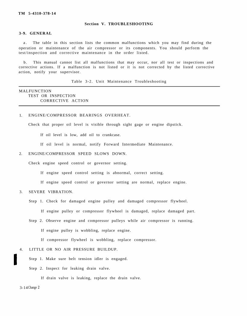
Section V. TROUBLESHOOTING
3-9. GENERAL
a . The table in this section lists the common malfunctions which you may find during theoperation or maintenance of the air compressor or its components. You should perform thetest / inspect ion and correct ive maintenance in the order l is ted.
b . This manual cannot list all malfunctions that may occur, nor all test or inspections andcorrective actions. If a malfunction is not listed or it is not corrected by the listed correctiveaction, notify your supervisor.
Table 3-2. Unit Maintenance Troubleshooting
MALFUNCTIONTEST OR INSPECTION
CORRECTIVE ACTION
1. ENGINE/COMPRESSOR BEARINGS OVERHEAT.
Check that proper oil level is visible through sight gage or engine dipstick.
If oil level is low, add oil to crankcase.
If oil level is normal, notify Forward Intermediate Maintenance.
2. ENGINE/COMPRESSOR SPEED SLOWS DOWN.
Check engine speed control or governor setting.
If engine speed control setting is abnormal, correct setting.
If engine speed control or governor setting are normal, replace engine.
3. SEVERE VIBRATION.
Step 1. Check for damaged engine pulley and damaged compressor flywheel.
If engine pulley or compressor flywheel is damaged, replace damaged part.
Step 2. Observe engine and compressor pulleys while air compressor is running.
If engine pulley is wobbling, replace engine.
If compressor flywheel is wobbling, replace compressor.
4. LITTLE OR NO AIR PRESSURE BUILDUP.
Step 1. Make sure belt tension idler is engaged.
Step 2. Inspect for leaking drain valve.
If drain valve is leaking, replace the drain valve.
3-14Change 2

TM 5-4310-378-14
Table 3-2. Unit Maintenance Troubleshooting (Continued)
MALFUNCTIONTEST OR INSPECTION
CORRECTIVE ACTION
If drain valve is not leaking, proceed to step 3.
Step 3. Inspect for leaks by applying a Leak Teck to valve body.
Pull out ring and release, valve should seat.
If safety valve is leaking or defective, replace safety valve.
If safety valve is not leaking or defective, proceed to step 4.
Step 4. Check for leaking or broken tubing.
If tubing is defect ive, replace defect ive tubing.
If the above steps do not correct the malfunction,Main tenance .
5. PRESSURE GAGE INACCURATE.
Check for damaged/defect ive pressure gage.
Rep lace damaged /de fec t i ve p re s su re gage .
6. EXCESSIVE OIL CONSUMPTION.
Notify Forward Intermediate Maintenance.
7. BELTS SLIP.
Step 1.
If
I f
Step 2.
If
Inspect for worn belts.
belts are worn, replace with new belts.
belts are not worn, proceed to step 2.
Inspect for proper belt tension (Table 3-1).
belt tension is improper,
8. ENGINE OVERHEATS
Check for oil level in crankcase,
If oil level is low, add oil.
not i fy Forward Intermediate
adjust belt tension (Table 3-1).
cooling fins clean, engine shrouds properly installed.
If cooling fins are dirty or caked with mud, clean them.
If shrouds are incorrectly installed or missing, install them correctly.
Change 2 3-15

TM 5-4310-378-14
Table 3-2. Unit Maintenance Troubleshooting (Continued)
MALFUNCTIONTEST OR INSPECTION
CORRECTIVE ACTION
9. ENGINE WILL NOT START.
Step 1. Loosen belt and try to turn compressor by hand.
If compressor does not turn, replace compressor.
If compressor turns, proceed to step 2.
Step 2. Check for proper operation of On/Off switch.
If On/Off switch is defective, replace On/Off switch.
If On/Off switch is not defective, notify Forward Intermediate Maintenance.
SECTION VI. MAINTENANCE PROCEDURES
3-10. GENERAL. This section contains the step-by-step procedures for performing maintenance for the com-pressor assembly. Personnel required are listed only if the task requires more than one. If personnel are not listed,it means one person can do the task.
3-11. BELT GUARD ASSEMBLY
This task covers: Replacement
Tools:7/16-in. wrench1/2-in. wrench
Materials: Brush, Cleaning (Appendix E,item 1)
Rag, Wiping (Appendix E,item 3)
Solvent, Dry Cleaning(Appendix E, item 2)
Belt Guard Assembly
Equipment Condition: Ignition switch pushed in (Table 2-1, 3).
Replacement. Replace defective beltguard assembly (1).
WARNING
To avoid injury, be sure to release belt tension beforeremoving belt guard assembly.
3-16 Change 3

Change 2
3-17
TM 5-4310-378-14
a. Removal.
(1) Use7/16-in. and 1/2-in. wrenches and remove two locknuts, two flat` washers, and twobolts from ends of belt guard.
(2) Use 7/16- in . wrench and removefrom lower side of belt guard.
(3) Use 7/16- in . wrench and removeguard (a t compressor bracket) .
(4) Remove bel t guard.
Ins t a l l a t i on .
two bolts, two flat washers, and two lock washers
one bolt and one lock washer from upper side of belt
(1) Obtain serviceable bel t guard and locate on the compressor uni t .
(2) Start attaching parts, one bolt and one lock washer at upper bracket; two bolts, twoflat washers, and two lock washers on lower side; and one bolt, one flat washer, andone locknut on each end of belt guard.
(3) Using 7/16-in. and 1/2-in. wrenches tighten all nuts and bolts equally.

TM 5-4310-378-14
3-12. MATCHED SET V-BELTS
This task covers:
Replacement
Materials: Brush, Cleaning (Appendix E, item 1)Rag, Wiping (Appendix E, item 3)Solvent, Dry Cleaning (Appendix E, item 2)V-Belt set
Equipment Condition: Ignition switch pushed in (Table 2-1,8).Belt guard assembly removed (Para 3-11).
Replacement. (Air compressor equipped with belt tension idler).
a. Removal.
Disengage belt tension idler, slide V-belts off of pulleys.
b. Instal lat ion.
Place V-belts over the two pulleys, engage belt tension idler.Install belt guard assembly (Para 3-11).
Replacement. (Air compressor not equipped with belt tension idler).
a. Removal.
(1) Using 7/16-in. wrench and 7/16-in socket and handle, loosen strut adjustment bolt and nut.
(2) Using 1/2-in. wrench and 1/2-in. socket and handle loosen engine mounting bolts.
(3) Slide engine along the frame toward the compressor until the V-belts are slack.
(4) Remove V-belts.
b. Instal lat ion.
(1) Place V-belts over the two pulleys.
(2) Slide engine along the frame away from the compressor until there is 1/2- inch deflection of theV-belts between the pulleys.
(3) Using 1-2-in. wrench and 1/2-in. socket and handle, tighten engine mounting hardware.
(4) Using 7/16-in. wrench and 7/16-in. socket and handle, tighten strut adjustment bolt and nut.
(5) Install belt guard assembly (Para 3-11).
3-18 Change 3

3-13. DRIVE PULLEY
This task covers:
Replacement
Tools:7/16-in. wrench
Materials: Brush, Cleaning (Appendix E,item 1)
Rag, Wiping (Appendix E,item 3)
Solvent, Dry Cleaning(Appendix E, item 2)
Drive Pulley
Equipment Condition: Ignition switchpushed in (Table 2-1, 8).
Belt guard assemblyremoved (Para 3-11).
V-belt set removed(Para 3-12).
TM 5-4310-378-14
Replacement. Replace defective drivepulley.
a. Removal.
(1) Using 7/16-in. wrench, remove two bolts (1) from drive pulley bushing (2).
(2) Remove bushing (2) and key (3) from drive pulley sheave (4).
(3) Pull sheave (4) from engine crankshaft.
b. Installation.
(1) Push drive pulley sheave (4) onto engine crankshaft.
(2) Align key (3) and bushing (2) and push them onto engine crankshaft.
(3) Align two bolt holes in bushing with two bolt holes in sheave and insert two bolts.
(4) Using 7/16-in. wrench, tighten bolts.
3-19

TM 5-4310-378-14
3-14. COMPRESSOR ASSEMBLY
This task covers:
a . I n spec t ion b . R e p l a c e m e n t
Tools :7/16-in. wrench and 7/16-in. socket and handle1/2-in. wrench13/16-in. wrench24-mm wrench
Mate r i a l s : Brush, Cleaning (Appendix E, item 1)Rag, Wiping (Appendix E, item 3)Solvent, Dry Cleaning (Appendix E, item 2)Compressor Assembly
Equipment Condi t ion: Ignition switch pushed in (Table 2-1, 8).Belt guard assembly removed (para 3-11).V-belts removed (para 3-12).
a . I n spec t i on .
Dry Cleaning Solvent(Stoddard Solvent)
P-D-680
Combustible - do not use near open flames, near welding areas, oron hot surfaces.Prolonged or repeated contact of skin with liquid can causedermati t is . Repeated inhalat ion of vapor can irr i tate nose andthroat and can cause dizziness.If any liquid contacts skin or eyes, immediately flush affected areathoroughly with water . Remove so lven t - s a tu r a t ed c lo th ing . I fvapors cause dizziness, go to fresh air.When handling liquid or when applying it in an air-exhausted,par t ia l ly covered tank, wear approved gloves.When handling liquid or when applying it at an unexhausted,uncovered tank or workbench, wear approved respirator, gogglesand gloves.
(1) Clean compressor as necessary to perform inspect ion. Use brush, c loth, and solventas required.
(2) Inspect compressor for excess wear or damage.
3-20

TM 5-4310-378-14
b. R e p l a c e m e n t .
( 1 ) R e m o v a l
(a)
(b)
(c)
(d)
(e)
(f)
Using 13/16-in. wrench, undo aftercooler assembly at compressor, loosen at tankenough to rotate af tercooler paral le l to tank.
Using l/2-in. wrench, undo pilot valve to compressor tube at pilot valve. Loosentube at valve end.
Using 7/16-in. wrench and 7/16-in. socket and handle, remove strut adjustmentnut and bolt.
Using l/2-in. socket wrench and handle, and l/2-in. wrench, remove four nuts,four bolts, and eight flat washers securing compressor assembly to frame.
Using 24-mm wrench, remove low pressure to high pressure cooling tube toremove compressor mount ing bol t .
Remove compressor assembly.
(2 ) In s t a l l a t i on
(a)
(b)
(c)
(d)
(e)
(f)
Using 24-mm wrench, loosen low pressure to high pressure cooling tube to insertcompressor mounting bol t below i t . Tighten cool ing tube.
Locate compressor assembly on frame and inser t remaining three bol ts throughmount ing holes .
Thread nuts onto bolts, and using 1/2-in. socket and handle and 1/2-in. wrench,t ighten mounting hardware equal ly .
Using 7/16-in. wrench and 7/16-in. socket and handle, install strut adjustment nutand bolt.
Using l/2-in. wrench install pilot valve to compressor tube at valve end.
Rotate af tercooler to instal l on compressor and instal l with 13/16-in. wrench.
3-15. TUBE ASSEMBLIES
This task covers:a . I n spec t ion b . R e p l a c e m e n t
Tools :l / 2 - i n . wrench19-mm wrench24-m m wrench
Mate r i a l s : Brush, Cleaning (Appendix E, item 1)Rag, Wiping (Appendix E, item 3)Solvent, Dry cleaning (Appendix E, item 2)
3-21

3-22
3-22
TM 5-4310-378-14
Equipment Condi t ion: Ignition switch pushed in (Table 2-1, 8).Tank drain valve open and air bleed off (Table 3-l).
a . I n spec t i on .
(1) Inspect intercooler tubing for damage(l) .
(2) Inspect af tercooler for damage(2) .
(3) Inspect unloader valve tubing for damage(3) .
(4) Inspect tee f i t t ings and elbows for damage.
b. Replacement . Replace defect ive tube assemblies , tee f i t t ings, and elbows as fol lows:
( 1 ) R e m o v a l
(a) Undo nuts a t each end of a defect ive tube.
( b ) R e m o v e t u b e f r o m c o m p r e s s o r .
(c) If fitting is to be removed, undo tube nuts and pull end of tube away enough tor emove f i t t i ng .
TM 5-4310-378-14
(2) Installation
(a) Install fittings removed in step b.
(b) Fit tubes into place and start nuts on each end onto their fittings.
(c) Tighten tube nuts to secure the assembly.
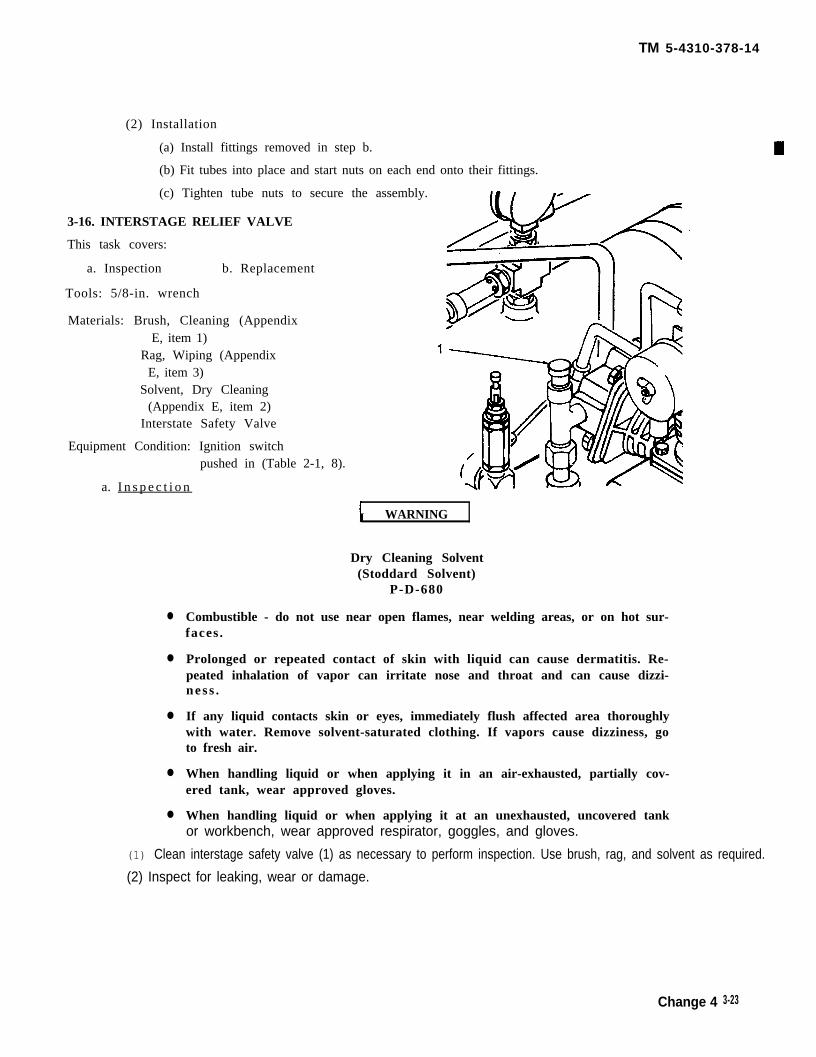
3-16. INTERSTAGE RELIEF VALVE
This task covers:
a. Inspection b. Replacement
Tools: 5/8-in. wrench
Materials: Brush, Cleaning (AppendixE, item 1)
Rag, Wiping (AppendixE, item 3)
Solvent, Dry Cleaning(Appendix E, item 2)
Interstate Safety Valve
Equipment Condition: Ignition switchpushed in (Table 2-1, 8).
a. I n s p e c t i o n
●
●
●
●
●
I WARNING
Dry Cleaning Solvent(Stoddard Solvent)
P-D-680
Combustible - do not use near open flames, near welding areas, or on hot sur-faces .
Prolonged or repeated contact of skin with liquid can cause dermatitis. Re-peated inhalation of vapor can irritate nose and throat and can cause dizzi-nes s .
If any liquid contacts skin or eyes, immediately flush affected area thoroughlywith water. Remove solvent-saturated clothing. If vapors cause dizziness, goto fresh air.
When handling liquid or when applying it in an air-exhausted, partially cov-ered tank, wear approved gloves.
When handling liquid or when applying it at an unexhausted, uncovered tankor workbench, wear approved respirator, goggles, and gloves.
(1) Clean interstage safety valve (1) as necessary to perform inspection. Use brush, rag, and solvent as required.
(2) Inspect for leaking, wear or damage.
Change 4 3-23

TM 5-4310-378-14
b. Replacement. Replace defective interstage relief valve as follows:
(1) Removal
(a) Using 5/8-in. wrench, remove interstage relief valve.
(2) Installation
(a) Install interstage relief valve.
3-17. COMPRESSOR AIR CLEANER
This task covers:
Replacement
Tools: Pipe wrench, adjustable jaw, one to two inches capacity.
Materials: Brush Cleaning (Appendix E, item 1)Rag, Wiping (Appendix E, item 3)Solvent, Dry Cleaning (Appendix E, item 2)Compressor Air Cleaner Assembly
Equipment Condition: Ignition switch pushed in (Table 2-1, 8).
Replacement. Replace defective air cleaner assembly as follows:
a. Removal.
I WARNING I
Dry Cleaning Solvent(Stoddard Solvent)
P-D-680
Combustible- do not use near open flames, near welding areas, or on hot sur-faces .
Prolonged or repeated contact of skin with liquid can cause dermatitis. Re-peated inhalation of vapor can irritate nose and throat and can cause dizzi-nes s .
If any liquid contacts skin or eyes, immediately flush affected area thoroughlywith water. Remove solvent-saturated clothing. If vapors cause dizziness, goto fresh air.
When handling liquid or when applying it in an air-exhausted, partially cov-ered tank, wear approved gloves.
When handling liquid or when applying it at an unexhausted, uncovered tankor workbench, wear approved respirator, goggles, and gloves.
(1) Clean compressor head, as necessary, using a clean, soft cloth (Appendix E, item 3) or a medium bristlebrush (Appendix E, item 1) and cleaning solvent (Appendix E, item 2).
(2) Using pipe wrench, carefully remove air cleaner assembly. Grip body (l).
3-24

TM 5-4310-378-14
b. Installation.
(1) Disassemble air cleaner and check to make certain that all parts are accounted for.
(2) Using pipe wrench, install aircleaner body on cylinder head.
(3) Install screen (2), filter (3), and cover (4).
(4) Install washer (5) and wing nut (6) and tighten wing nut to secure the completeassembly.
3-25

TM 5-4310-378-14
3-18. OIL FILLER CAP AND SIGHT GLASS
This task covers:
R e p l a c e m e n t
Tools :Pliers, Slip Joint
Mate r i a l s : Oil Filler CapSight GlassSight Glass Seal
Equipment Condi t ion: Ignition switch pushed in (Table 2-1, 8).Compressor crankcase drained (para 3-2) .
R e p l a c e m e n t
a . R e m o v a l .
(1) Unscrew and remove oi l f i l ler cap.
(2) Using a pair of pliers remove sight glass and sight glass seal. Discard seal.
b . I n s t a l l a t i on .
(1) Install new sight glass seal and sight glass.
(2) Instal l oi l f i l ler cap or crankcase.
(3) Fill crankcase with oil per paragraph 3-2.
3-19. COMPRESSOR FLYWHEEL
This task covers:
a . I n spec t ion b . R e p l a c e m e n t
Tools : 13-mm WrenchGear Puller
Mate r i a l s : Brush, Cleaning (Appendix E, item 1)Rag, Wiping (Appendix E, item 3)Solvent, Dry Cleaning (Appendix E, item 2)Compressor FlywheelFlywheel Thrust WasherFlywheel Thrust Bolt
Equipment Condi t ion: Ignition switch pushed in (Table 2-1, 8).Tank drain valve open and air bleed off (Table 3-1)Belt guard assembly removed (para 3-11).V-belts removed (para 3-12).
3-26

TM 5-4310-378-14
a. Inspection.
(1) Inspect for missing or damaged hardware.
(2) Inspect compressor flywheel for damage
b. Replacement Replace defective compressor flywheel as follows:
(1) Removal
(a) Remove flywheel thrust bolt and washer.
(b) Using gear puller, remove flywheel.
●
●
●
●
●
(2)
Dry Cleaning Solvent(Stoddard Solvent)
P-D-680
Combustible - do not use near open flames, near welding areas,or on hot surfaces.Prolonged or repeated contact of skin with liquid can causedermatitis. Repeated inhalation of vapor can irritate nose andthroat and can cause dizziness.If any liquid contacts skin or eyes, immediately flush affectedarea thoroughly with water. Remove solvent-saturatedclothing. If vapors cause dizziness, go to fresh air.When handling liquid or when applying it in an air-exhausted,partially covered tank, wear approved gloves.When handling liquid or when applying it at an unexhausted,uncovered tank or workbench, wear approved respirator,goggles, and gloves.
Installation
(a) Use brush, rag, and solventinstalling flywheel.
(b) Install flywheel and secure
as necessary to clean compressor crankcase before
with thrust washer and thrust bolt.
3-27

TM 5-4310-378-14
3-20. UNLOADER
This task covers:
a . I n spec t ion
VALVE ASSEMBLIES
b . R e p l a c e m e n t
Tools : 17-mm wrench
Mate r i a l s : Auto Unloader Piston Packing (3 each)Brush, Cleaning (Appendix E, item 1)Rag, Wiping (Appendix E, item 3)Solvent, Dry cleaning (Appendix E, item 2)
Equipment Condi t ion: Ignition switch pushed in (Table 2-1, 8)Tank drain valve open and air bleed-off (Table 3-l).Air cleaners removed (para 3-17).Tubing assemblies, elbow, and tees removed (para 3-15).
a. Inspection
Dry Cleaning Solvent(Stoddard Solvent)
P-D-680
Combustible - do not use near open flames, near welding areas,or on hot surfaces.Prolonged or repeated contact of skin with liquid can causedermati t is . Repeated inhalat ion of vapor can irr i tate nose andthroat and can cause dizziness.If any liquid contacts skin or eyes, immediately flush affectedarea thoroughly with water . Remove solvent-saturatedclothing. If vapors cause dizziness, go to fresh air.When handling liquid or when applying it in an air-exhausted,par t ia l ly covered tank, wear approved gloves.When handling liquid or when applying it at an unexhausted,uncovered tank or workbench, wear approved respira tor ,goggles, and gloves.
(1) Clean, as necessary, using a clean, soft cloth (Appendix E, item 3) or a medium bristlebrush (Appendix E, item 1) and cleaning solvent (Appendix E, item 2).
(2) Inspect for miss ing or damaged hardware.
3-28

TM 5-4310-378-14
b . R e p l a c e m e n t . R e p l a c e d e f e c t i v eunloader valves as follows:
( 1 ) R e m o v a l
( a ) R e m o v e a u t o - u n l o a d e rcylinder (l), auto-unloaderpiston (2), packing (3), andspring (4). Discard packing.
(2 ) In s t a l l a t i on
(a) Instal l new packing (3) onpiston (2).
(b) Inser t spr ing (4) and pis ton(2) with packing (3) intocyl inder ( l ) .
(c) Instal l cyl inder (1) intocyl inder head.
3-21. ENGINE ASSEMBLY
This task covers:
a . I n spec t ion b . R e p l a c e m e n t
Tools :l /2- in . wrench and l /2- in . socket with handle
Mate r i a l s : Brush, Cleaning (Appendix E, item 1)Rag, Wiping (Appendix E, item 3)Solvent, Dry cleaning (Appendix E, item 2)Engine Assembly
Equipment Condi t ion: Ignition switch pushed in (Table 2-1, 8).Fuel tank drained (Table 2-1, 7).V-belts removed (para 3-12).Driving pulley and key removed (para 3-13).
3-29
TM 5-4310-378-14
a. Inspection.
b.
●
●
●
●
●
(1)
(2)
(3)
Dry Cleaning Solvent(Stoddard Solvent)
P-D-680
Combustible - do not use near open flames, near welding areas,or on hot surfaces.Prolonged or repeated contact of skin with liquid can causedermati t is . Repeated inhalat ion of vapor can irr i tate nose andthroat and can cause dizziness.If any liquid contacts skin or eyes, immediately flush affectedarea thoroughly with water . Remove solvent-saturatedclothing. If vapors cause dizziness, go to fresh air.When handling liquid or when applying it in an air-exhausted,par t ia l ly covered tank, wear approved gloves.When handling liquid or when applying it at an unexhausted,uncovered tank or workbench, wear approved respira tor ,goggles, and gloves.
Use brush, rag, and solvent as necessary to clean engine to facilitate engineinspect ion.
Inspect engine for loose, or broken parts, clogged cooling fins, frayed recoil starterr o p e .
Inspect engine for wobbly crankshaft.
R e p l a c e m e n t .
( 1 ) R e m o v a l
(a) Remove four nuts and bolts and eight washers securing
(b) Lif t engine from frame and discard in accordance with
(2 ) In s t a l l a t i on
engine to frame.
local regulations.
(a) Set replacement engine on frame and insert four bolts thru washers, the engine,and the frame.
(b) Install another washer and a nut on each bolt. Do not tighten until the V-beltsare set and adjusted.
3-30

TM 5-4310-378-14
3-22. FUEL TANK AND FUEL FILTER ASSEMBLIES
This task covers:
a. Service b. Replacement
Tools:7/16-in. WrenchPliers, Slip Joint10-mm Wrench14-mm Wrench
Materials: Brush, Cleaning(Appendix E, item 1)
Rag, Wiping(Appendix E, Item 3)
Solvent, Dry Cleaning(Appendix E, item 2)
Fuel Tank AssemblyFuel Filter AssemblyFuel Line Assembly
Equipment Condition: Ignition switchpushed in (Table 2-1, 8).
Fuel tank drained (Table 2-1, 7).
a. Service.
(1)
(2)
Combustible - do not use near open flames, near welding areas,or on hot surfaces.Prolonged or repeated contact of skin with liquid can causedermatitis. Repeated inhalation of vapor can irritate nose andthroat and can cause dizziness.If any liquid contacts skin or eyes, immediately flush affectedarea thoroughly with water. Remove solvent-saturatedclothing. If vapors cause dizziness, go to fresh air.When handling liquid or when applying it in an air-exhausted,partially covered tank, wear approved gloves.When handling liquid or when applying it at an unexhausted,uncovered tank or workbench, wear approved respirator,goggles, and gloves.
Clean fuel filter as necessary using brush, rag, and solvent.
Remove and discard bowl (l), gasket (2), and screen (3).
3-31

TM 5-4310-378-14
CAUTION
Do not overtighten bowlin step 3.
(3) Instal l fuel s t rainer repair ki tconsisting of: bowl (l), gasket (2),and screen (3).
(4) Remove fuel tank f i l ler cover andextract fuel s t rainer f rom tank.
WARNING
Dry Cleaning Solvent(Stoddard Solvent)
P-D-680
Combustible - do not use nearopen flames, near weldingareas, or on hot surfaces.Prolonged or repeated contactof skin with liquid can caused e r m a t i t i s . R e p e a t e dinhalation of vapor canirr i tate nose and throat andcan cause dizziness.If any liquid contacts skin oreyes, immediately f lushaffected area thoroughly withwa te r . Remove so lven t -saturated clothing. I f vaporscause dizziness, go to fresha i r .When handling liquid or whenapplying it in an air-exhausted, part ial ly coveredtank, wear approved gloves.When handling liquid or whenapplying it at-an unexhausted,uncovered tank or workbench,wear approved respirator andgoggles .
(5) Clean fuel s t rainer by back f lushingwith solvent .
(6) Shake off dirt and excess solvent.
(7) Install fuel strainer in fuel tank.Replace cover .
3-32
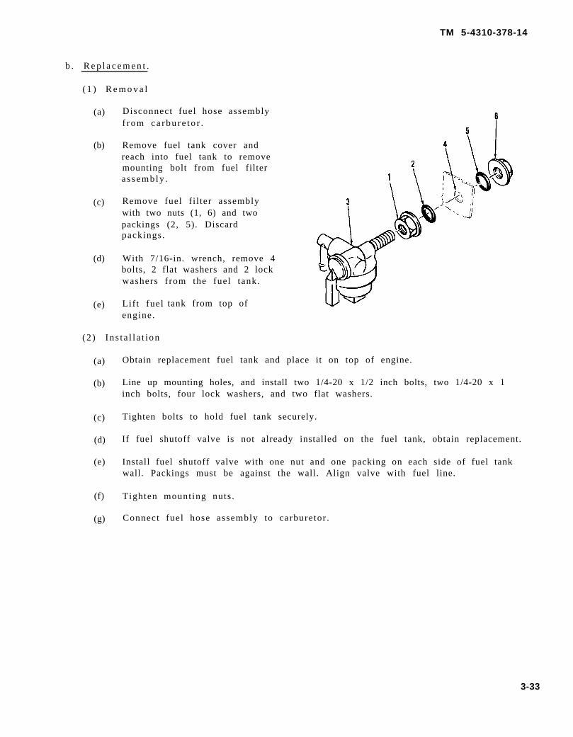
TM 5-4310-378-14
b . R e p l a c e m e n t .
( 1 ) R e m o v a l
(a)
(b)
(c)
(d)
(e)
Disconnect fuel hose assemblyf r o m c a r b u r e t o r .
Remove fuel tank cover andreach into fuel tank to removemounting bolt from fuel filtera s sembly .
Remove fuel f i l ter assemblywith two nuts (1, 6) and twopackings (2, 5). Discardpackings.
With 7/16-in. wrench, remove 4bolts, 2 flat washers and 2 lockwashers f rom the fuel tank.
Lif t fuel tank from top ofengine.
(2 ) In s t a l l a t i on
(a)
(b)
(c)
(d)
(e)
(f)
(g)
Obtain replacement fuel tank and place it on top of engine.
Line up mounting holes, and install two 1/4-20 x 1/2 inch bolts, two 1/4-20 x 1inch bolts, four lock washers, and two flat washers.
Tighten bolts to hold fuel tank securely.
If fuel shutoff valve is not already installed on the fuel tank, obtain replacement.
Install fuel shutoff valve with one nut and one packing on each side of fuel tankwall. Packings must be against the wall. Align valve with fuel line.
Tighten mount ing nuts .
Connect fuel hose assembly to carburetor .
3-33
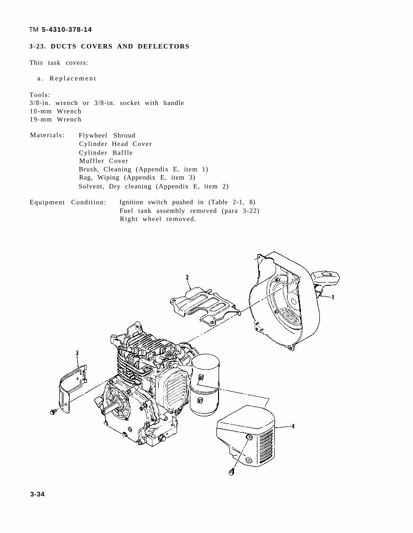
TM 5-4310-378-14
3-23. DUCTS COVERS AND DEFLECTORS
This task covers:
a . R e p l a c e m e n t
Tools :3/8-in. wrench or 3/8-in. socket with handle10-mm Wrench19-mm Wrench
Mate r i a l s : Flywheel ShroudCylinder Head CoverCylinder Baff leMuffler CoverBrush, Cleaning (Appendix E, item 1)Rag, Wiping (Appendix E, item 3)Solvent, Dry cleaning (Appendix E, item 2)
Equipment Condi t ion: Ignition switch pushed in (Table 2-1, 8)Fuel tank assembly removed (para 3-22)Right wheel removed.
3-34

a .
TM 5-4310-378-14
Replacement . Replace defect ive parts as fol lows: (If a part is not defect ive i t is notnecessary to replace i t . )
( 1 ) R e m o v a l
(a) Remove four bol ts securing recoi l s tar ter assembly (1) to f lywheel shroud. Placerecoil starter assembly to one side.
(b) Remove four bol ts , two brackets , and s t rut securing the f lywheel shroud. Pul l shroudfrom the engine far enough to disconnect wire from coaxial filter.
(c) Remove coaxial f i l ter and igni t ion switch from f lywheel shroud.
(d) Remove spark plug lead from spark plug.
(e) Remove cyl inder head cover (2) f rom engine.
(f) Remove one bolt securing cylinder baffle (3) and disengage end of baffle fromcy l inde r .
(g) Remove three bolts securing muffler cover (4) and pull cover from muffler.
(2 ) In s t a l l a t i on
(a)
(b)
(c)
(d)
(e)
(f)
(g)
(h)
(i)
Obtain replacement parts as necessary.
Locate muffler cover (4) on muffler and secure with three bolts.
Engage cylinder baffle (3) in position on cylinder and secure with one bolt.
Locate cylinder head cover (2) on top of engine. Match mounting holes in coverwith holes in cylinder head.
Connect spark plug lead.
Install coaxial filter and ignition switch in flywheel shroud.
Hold flywheel shroud close to its location on engine and connect ignition wire tocoaxial f i l ter .
Secure flywheel shroud with four bolts, two brackets, and the strut.
Install recoil starter (1) with four bolts.
3-35

This task covers:
T o o l s :19-mm Socket with handle and extensionTorque WrenchW h e e l P u l l e r
TM 5-4310-378-14
3-24. FLYWHEEL
a. Inspection b. Replacement
M a t e r i a l s : F l y w h e e l
Equipment Condi t ion: Ignition switch pushed in (Table 2-1, 8).Right wheel removed.Flywheel shroud and recoil starter removed (para 3-23).
a . Inspect ion. Inspect f lywheel fordamage that could cause it to vibratewhile rotat ing. Excess vibrat ion whenengine is running could mean that theflywheel is out of balance.
b . R e p l a c e m e n t .
( 1 ) R e m o v a l
(a)
(b)
(2)
(a)
(b)
(c)
(d)
(e)
Starting pulley (6), washer (4)and nut (5)
Using wheel puller removeflywheel (3) , extract woodruffkey (l).
In s t a l l a t ion
Obtain replacement f lywheel (3) .
Insert woodruff key (1) in position on shaft (2)
Place flywheel (3) on shaft with key slot lined up with key (l).
Install lock washer (4), nut (5), and starting pulley (6).
Torque nut (5) to 44.0 to 47.0 ft lb (59.7 to 63.7 N •m ) .
3-36

TM 5-4310-378-14
3-25. ENGINE IGNITION COIL
This task covers:
a. Inspection b. Testing c. Replacement
Tools: Multimeter, type TS-352 B/U10-mm Wrench
Materials: Brush, Cleaning (Appendix E, item 1)Rag, Wiping (Appendix E, item 3)Solvent, Dry Cleaning (Appendix E, item 2).Ignition Coil
Equipment Condition: Ignition switch pushed in (Table 2-1, 8).Right wheel removed from handtruck.Flywheel shroud and recoil starter removed (para 3-23).
a. I n spec t i on
●
●
●
●
●
I WARNING I
Dry Cleaning Solvent(Stoddard Solvent)
P-D-680
Combustible - do not use near open flames, near welding areas, or on hot sur-faces.
Prolonged or repeated contact of skin with liquid can cause dermatitis. Re-peated inhalation of vapor can irritate nose and throat and can cause dizzi-ness.
If any liquid contacts skin or eyes, immediately flush affected area thoroughlywith water. Remove solvent-saturated clothing. If vapors cause dizziness, goto fresh air.
When handling liquid or when applying it in an air-exhausted, partially cov-ered tank, wear approved gloves.
When handling liquid or when applying it at an unexhausted, uncovered tankor workbench, wear approved respirator, goggles, and gloves.
(1) Use brush, rag, and solvent to clean as necessary.
(2) Inspect for disconnected, loose, or broken wires to the ignition coil.
(3) Cable leading from ignition coil to spark plug is not wet or oil soaked.
b. Testing. Use a multimeter to check ignition coil for continuity. Resistance should be greater than 1 megohm.
3-37
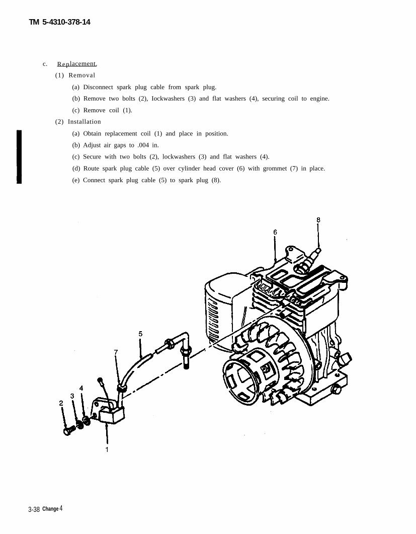
TM 5-4310-378-14
c. Replacement.
(1) Removal
(a) Disconnect spark plug cable from spark plug.
(b) Remove two bolts (2), Iockwashers (3) and flat washers (4), securing coil to engine.
(c) Remove coil (1).
(2) Installation
(a) Obtain replacement coil (1) and place in position.
(b) Adjust air gaps to .004 in.
(c) Secure with two bolts (2), lockwashers (3) and flat washers (4).
(d) Route spark plug cable (5) over cylinder head cover (6) with grommet (7) in place.
(e) Connect spark plug cable (5) to spark plug (8).
3-38 Change 4

TM 5-4310-378-14
3-26. IGNITION SWITCH
This task covers:
a . I n spec t ion b . T e s t i n g
Tools :Mult imeter , Type TS-352 B/U
c . R e p l a c e m e n t
9/16-in. Wrench
Mate r i a l s : Brush, Cleaning (Appendix E, item 1)Rag, Wiping (Appendix E, item 3)Solvent, Drycleaning (Appendix E, item 2)Ignition Switch
Equipment Condi t ion: Ignition switch pushed in (Table 2-1, 8).Right wheel removed from hand truck.Flywheel shroud and recoil starter removed (para 3-23).
a .
b .
c .
I n spec t i on
(1) Inspect igni t ion switch forcorrosion, obvious burn spots orother damage, and rougho p e r a t i o n .
(2) Damage to the switch or roughoperat ion indicate a defect iveswi t ch .
Tes t ing .
(1) Use a mult imeter to test switchfor cont inui ty .
(2 ) Res i s t ance be tween swi t chterminals and ground should begreater than 1 megohm
(3) I f less than 1 megohm, replaceigni t ion switch.
R e p l a c e m e n t .
( 1 ) R e m o v a l
( a ) R e m o v e i g n i t i o n s w i t c hmounting nut (3) and plate(2).
(b ) D i sconnec t c ab l e a s sembly(4) from ignition switch (l).
( c ) Remove ign i t i on swi t ch ( l ) .
3-39
TM 5-4310-378-14
(2 ) In s t a l l a t i on
(a ) Ob ta in r ep l acemen t i gn i t i on swi t ch ( l ) .
(b) Install ignition switch (1) with plate (2) and mounting nut (3).
(c) Connect cable assembly (4) to igni t ion switch.
3 - 2 7 . S P A R K P L U G
This task covers:
a . I n spec t ion b . S e r v i c e
Tools :19-mm Wrench20-mm Deep Socket Wrench with HandleGap Set t ing Gage
Mate r i a l s : Brush, Cleaning (Appendix E, item 1)Rag, Wiping (Appendix E, item 3)Solvent, Dry cleaning (Appendix E, item 2)Spark Plug
Equipment Condi t ion: Ignition switch pushed in (Table 2-1, 8).
a . I n spec t i on .
c . R e p l a c e m e n t
I WARNINGI
●
●
●
●
●
Dry Cleaning Solvent(Stoddard Solvent)
P-D-680
Combustible - do not use near open flames, near welding areas,or on hot surfaces.Prolonged or repeated contact of skin with liquid can causedermatitis. Repeated inhalation of vapor can irritate nose andthroat and can cause dizziness.If any liquid contacts skin or eyes, immediately flush affectedarea thoroughly with water. Remove solvent-saturatedclothing. If vapors cause dizziness, go to fresh air.When handling liquid or when applying it in an air-exhausted,partially covered tank, wear approved gloves.When handling liquid or when applying it at an unexhausted,uncovered tank or workbench, wear approved respira tor ,goggles, and gloves.
(1) Clean engine as necessary using brush, rag, and solvent.
(2) Remove spark plug from engine and inspect for corroded electrodes .
(3) I f e lectrodes are corroded discard spark plug.
3-40

TM 5-4310-378-14
b. S e r v i c e . Use a gap setting gage to adjust spark plug gap to 0.024 to 0.027 inch (0.6 to0.7 mm).
c. R e p l a c e m e n t .
( 1 ) R e m o v a l
(a) Remove defect ive spark plug.
(2 ) In s t a l l a t i on
(a) Install spark plug gasket over spark plug and insert spark plug in hole in head.Torque spark plug 8.7 to 10.8 foot pounds (11.8 to 14.6 N •m ) .
3-28. ENGINE AIR CLEANER
This task covers:
a . S e r v i c e b . R e p l a c e m e n t
Tools : 10-mm Wrench
Mate r i a l s : Brush, Cleaning(Appendix E, item 1)
Rag, Wiping (Appendix E,item 3)
Solvent , Dry cleaning(Appendix E, item 2).
Kerosene (Appendix E,item 8)
Air Cleaner Assembly
Equipment Condi t ion: Ignit ion switchpushed in(Table 2-1, 8).
a. S e r v i c e .
(1) Release clip (1) and remove cover (2).
(2) Remove element (3) and retainer (4) from body (5).
(3) Remove all buildup of dirt, grease, etc., by wiping with a soft cloth (Appendix E,item 3).
(4) Wash element (3) in kerosene. Wrap in a clean cloth and squeeze dry.
(5) Saturate element with kerosene, then squeeze out the excess .
3-41
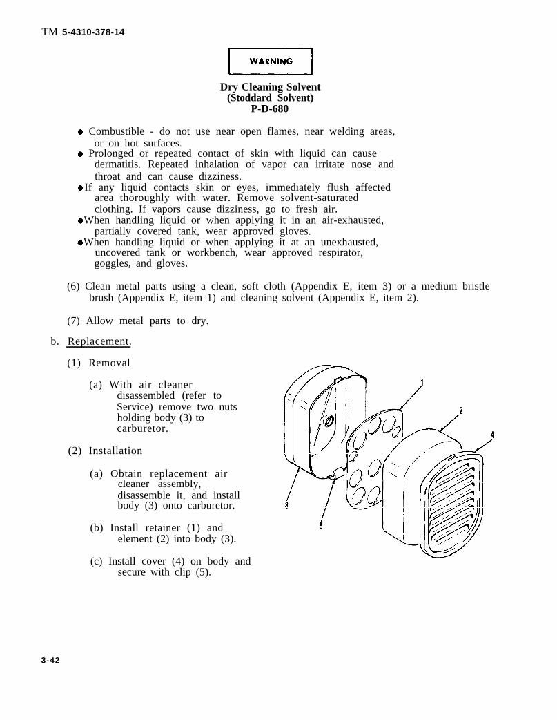
TM 5-4310-378-14
Dry Cleaning Solvent(Stoddard Solvent)
P-D-680
Combustible - do not use near open flames, near welding areas,or on hot surfaces.
Prolonged or repeated contact of skin with liquid can causedermatitis. Repeated inhalation of vapor can irritate nose andthroat and can cause dizziness.
If any liquid contacts skin or eyes, immediately flush affectedarea thoroughly with water. Remove solvent-saturatedclothing. If vapors cause dizziness, go to fresh air.
When handling liquid or when applying it in an air-exhausted,partially covered tank, wear approved gloves.
When handling liquid or when applying it at an unexhausted,uncovered tank or workbench, wear approved respirator,goggles, and gloves.
(6) Clean metal parts using a clean, soft cloth (Appendix E, item 3) or a medium bristlebrush (Appendix E, item 1) and cleaning solvent (Appendix E, item 2).
(7) Allow metal parts to dry.
b. Replacement.
(1) Removal
(a) With air cleanerdisassembled (refer toService) remove two nutsholding body (3) tocarburetor.
(2) Installation
(a) Obtain replacement aircleaner assembly,disassemble it, and installbody (3) onto carburetor.
(b) Install retainer (1) andelement (2) into body (3).
(c) Install cover (4) on body andsecure with clip (5).
3-42
TM 5-4310-378-14
3-29. AIR CLEANER ELEMENT
This task covers:
a . R e p l a c e m e n t
Mate r i a l s : Rag, Wiping (Appendix E, item 3)Kerosene (Appendix E, item 8)
Equipment Condi t ion: Ignition switch pushed in (Table 2-1, 8).Air c leaner e lement removed (para 3-28) .
a . R e p l a c e m e n t
(1 ) Ob ta in r ep l acemen t e l emen t .
(2) Saturate element with kerosene, then squeeze out the excess .
(3) Place element in air c leaner body.
(4) Install air cleaner cover and secure with clip.
3-30. CARBURETOR
This task covers:
a . I n spec t ion b . S e r v i c e c . A d j u s t m e n td . R e p l a c e m e n t
Tools :10-mm Wrench12-mm Wrench
Mate r i a l s : Brush, Cleaning (Appendix E, Item 1)Rag, Wiping (Appendix E, item 3)Solvent, Dry cleaning (Appendix E, item 2)
Equipment Condi t ion: Ignition switch pushed in (Table 2-1, 8).Engine air cleaner removed (para 3-28).
3-43

TM 5-4310-378-14
a. I n s p e c t i o n .
Combustible - do not use near open flames, near welding areas,or on hot surfaces.Prolonged or repeated contact of skin with liquid can causedermati t is . Repeated inhalat ion of vapor can irr i tate nose andthroat and can cause dizziness.If any liquid contacts skin or eyes, immediately flush affectedarea thoroughly with water . Remove solvent-saturatedclothing. If vapors cause dizziness, go to fresh air.When handling liquid or when applying it in an air-exhausted,par t ia l ly covered tank, wear approved gloves.When handling liquid or when applying it at an unexhausted,uncovered tank or workbench, wear approved respira tor ,goggles, and gloves.
(1) Clean carburetor as necessaryusing brush, rag, and solvent.
(2) Inspect carburetor for damage, andloose, or missing parts.
b. S e r v i c e .
(1) Close fuel shutoff . Remove screw(1) and washer (2) holding floatchamber (3) on carburetor (4).Discard gasket (5).
(2) Empty float chamber (3) and wipeit clean inside and out with awiping rag (Appendix E, item 3).
(3) Install float chamber (3) and newgasket (5). Secure with washer (2)and screw (l).
c. A d j u s t m e n t . With the engine running,rotate speed control lever s top screw(1) until the engine is idling at the mostfavorable speed.
3-44

TM 5-4310-378-14
d. R e p l a c e m e n t .
( 1 ) R e m o v a l
( a ) S l i d e d e f e c t i v e c a r b u r e t o r (6) off mount ing s tuds . Discard carburetor f langegasket (2), insulating plate gasket (4), and air cleaner gasket (7).
(b)
Dry Cleaning Solvent(Stoddard Solvent)
P-D-680
Combustible - do not use near open flames, near welding areas,or on hot surfaces.Prolonged or repeated contact of skin with liquid can causedermati t is . Repeated inhalat ion of vapor can irr i tate nose andthroat and can cause dizziness .If any liquid contacts skin or eyes, immediately flush affecteda rea t ho rough ly w i th wa te r . Remove so lven t - s a tu r a t edclothing. If vapors cause dizziness, go to fresh air.When handling liquid or when applying it in an air-exhausted,par t ia l ly covered tank, wear approved gloves.When handling liquid or when applying it at an unexhausted,uncovered tank or workbench, wear approved respira tor ,goggles, and gloves.
Clean carburetor mounting boss (1) on the crankcase as necessary with brush, rag,and solvent .
(2 ) In s t a l l a t i on
(a)
(b)
(c)
(d)
(e)
Obtain replacement carburetor (6) and new gaskets (2, 4, 7).
Slide insulating plate gasket (2), carburetor insulating plate (3), and carburetorflange gasket (4) onto carburetor mounting studs (5).
Slide carburetor assembly (6) onto mounting studs (5) and slide air cleanergasket (7) against it.
Slide the air cleaner body (8) onto studs, with the clip down, and secure thecomplete installation with two nuts (9).
Adjust carburetor per subparagraph c (adjustment) .
3-4

TM 5-4310-378-14
3-46

TM 5-4310-378-14
ALL DATA ON THIS PAGEDELETED
Change 3 3-47

subparagraph b
TM 5-4310-378-14
3-32. GOVERNOR ROD ASSEMBLY
This task covers:
a . I n spec t ion b . A d j u s t m e n t c . R e p l a c e m e n t
Equipment Condi t ion: Ignition switch pushed in (Table 2-1, 8).
a.
b.
c.
Inspect ion.
(1) Inspect governor rod (3) forunwanted bends, or missing springs(4, 8).
Ad jus tmen t .
(1) Install spring (8) in hole No. 2 incontrol lever (6).
R e p l a c e m e n t
( 1 ) R e m o v a l
(a) Remove springs (4, 8) andgovernor rod (3).
(2 ) In s t a l l a t i on
(a)
(b)
3-48

TM 5-4310-378-14
3-33. GOVERNOR CONTROL ASSEMBLY
This task covers:
a. Inspection
Tools:10-mm Wrench
Equipment Condition: Left wheel removed.
a. Inspection. Inspect governor control assembly for bent, broken or corroded parts.
Change 3 3-49

TM 5-4310-378-14
ALL DATA ON THISPAGE DELETED
3-50 Change 3

TM 5-4310-378-14
3-34. RECOIL STARTER ASSEMBLY
This task covers:
a . I n spec t ion b . R e p l a c e m e n t
Tools : 19-mm Socket withTorque Wrench10-mm Wrench
Mate r i a l s : Brush, Cleaning
c . R e p a i r
handle and extension
(Appendix E, item 1)Rag, Wiping (Appendix E, item 3)Solvent, Dry Cleaning (Appendix E, item 2)Recoil Starter Assembly
Equipment Condi t ion: Ignition switch pushed in (Table 2-1, 8).Right wheel removed.
a. I n s p e c t i o n .
Dry Cleaning Solvent(Stoddard Solvent)
P-D-680
Combustible - do not use near open flames, near welding areas, oron hot surfaces.Prolonged or repeated contact of skin with liquid can causedermati t is . Repeated inhalat ion of vapor can irr i tate nose andthroat and can cause dizziness .If any liquid contacts skin or eyes, immediately flush affected areathoroughly with water . Remove so lven t - s a tu r a t ed c lo th ing . I fvapors cause dizziness, go to fresh air.When handling liquid or when applying it in an air-exhausted,par t ia l ly covered tank, wear approved gloves.When handling liquid or when applying it at an unexhausted,uncovered tank or workbench, wear approved respira tor , goggles ,and gloves.
(1) Use brush, rag, and solvent as necessary to clean recoil starter assembly and flywheelshroud.
( 2 ) I n s p e c t f o r
( 3 ) I n s p e c t f o r
( 4 ) I n s p e c t f o r
broken or badly frayed rope.
smooth operation when rope handle is pulled and released.
damage that may interfere with recoi l s tar ter operat ion.
3-51

TM 5-4310-378-14
b . R e p l a c e m e n t .
( 1 ) R e m o v a l
( a ) R e m o v e
( b ) R e m o v e
( c ) R e m o v esha f t .
four bolts securing recoil starter assembly (3) to flywheel shroud (4).
recoil starter assembly (3).
engine flywheel nut (2) and washer, pull starting pulley (1) from flywheel
NOTE
If repair of recoil starter assembly is required, proceed to nextpa rag raph : Repa i r .
(2 ) In s t a l l a t i on
(a) Obtain replacement recoi l s tar ter assembly (3) and s tar t ing pul ley ( l ) .
(b) Install starting pulley (1) on engine flywheel shaft and secure with washer andengine flywheel nut (2). Torque to 44.0 to 47.0 ft-lb (59.7 top 6.3 N •m ) .
(c) Install recoil starter assembly (3) on flywheel shroud (4). Secure with four bolts.
3-52

TM 5-4310-378-14
Figure 9. Recoil Starter Assembly
c . R e p a i r .
NOTE
This procedure goes all the way through disassembly andassembly. I t is only necessary to disassemble the recoi ls tar ter assembly enough to correct the faul t . After thedefective parts have been removed it is possible to assemblethe recoi l s tar ter assembly from that point .
(1) Remove recoil starter assembly (1) from flywheel shroud. If it is not necessary to
(2)
(3)
(4)
(5)
(6)
remove the starting pulley (2) from the flywheel, leave it there.
Pull about 14 inches (355 mm) of rope (3) out of recoil starter assembly (l).
Press thumb against ratchet retainer (4) to prevent reel (5) from unwinding.
Lock rope (3) in notch on outer rim of reel (5).
Release thumb pressure against ratchet retainer
Twist loop of return spring (7) so that it will slip
(4) and let power spring (6) unwind.
through slot in ratchet retainer (4).
3-53

TM 5-4310-378-14
(7)
(8)
(9)
( l 0 )
(11)
(12)
(13)
(14)
(15)
(16)
(17)
(18)
(19)
(20)
(21)
(22)
(23)
Remove clip (8), thrust washer (9), and ratchet retainer (4). Reel (5) will completelyunwind as these parts are removed.
Take out compression spring (10), return spring (7), and two ratchets (11). The endof return spring (7) is hooked in a hole in the reel (5) hub.
Use care to ensure that power spring (6) remains in recess ofhousing (12) and does not pop out. Do not removespring (6) except for replacement .
Slowly lift reel (5) from support shaft in housing (12).is purposely removed, perform steps 10 through 14 to
p o w e r
If power spring (6) escapes orinstal l i t .
Obtain a piece of 16 or 18 gauge soft iron wire approximately 15 inches (381 mm)long and twist the ends together to form a loop 3.15 inches (80 mm) inside diameter.
Wind the power spring (6) inside the wire loop; start with the outer loop of the springand wind in a counterclockwise direction.
Place the power spring (6) and wire loop assembly over the recess in the reel (5).
Align the hook in the outer loop of the power spring (6) over the tension tab in thereel (5).
Carefully press the spring out of the wire loop and into the recess in the reel (5).
Remove pieces of broken rope. Discard.
Install free end (without handle) of rope assembly (3) into guide bushing of housing(12) and through hole in reel (5) groove.
Pull rope (3) out through cavity opening and tie an overhand knot about 1 inch (25mm) from end.
Stuff knot into cavity opening.
Spread a film of light grease on power spring (6) and support shaft.
Install the reel (5) so that inner loop of power spring (6) engages the tang next to thesupport shaft in the housing (12).
Wind rope assembly (3) 2-1/2 turns clockwise in reel (5) and lock rope in notch ofreel pul ley.
Turn reel (5) counterclockwise until tang engages notch in power spring.
Use fingers to restrain the reel (5) and keep it from popping out and unwinding.
3-54

(24)
(25)
(26)
(27)
(28)
(29)
(30)
(31)
TM 5-4310-378-14
With the rope (3) hooked into the reel (5) notch, obtain spring tension by turning thereel four revolutions counterclockwise.
Remove rope (3) from notch in reel (5) pulley and let reel slowly turn clockwise asrope winds onto reel and handle returns to guide bushing on housing (12).
Install compression spring (1O).
Install return spring (7) with bent end hooked into hole of reel (5) hub and looped endtoward the outside.
Install ratchets (11) so they fit the contour of the recesses in the reel (5) hub (tipspointed in a counterclockwise direction).
Install ratchet retainer (4) so that loop end of return spring (7) extends through slot.
Rotate ratchet retainer (4) slightly clockwise until the two small slots in theretainer just begin to engage the two ratchets (11).
Press down on ratchet retainer (4) and install thrust washer (9) and clip (8).
3-35. CYLINDER HEAD AND GASKET
This task covers:
Service
Materials: Brush, Cleaning (Appendix E, item 1)Rag, Wiping (Appendix E, item 3)Solvent, Dry cleaning (Appendix E, item 2).
Equipment Condition: Ignition switch pushed in (Table 2-1, 8).Fuel tank drained and removed (para 3-22).Flywheel shroud removed (para 3-23).
a. Service.
(1) Remove dirt from betweencooling fins.
(2) Check cylinder head (2) fordistortion. If head is warped,notify supervisor.
3-55

TM 5-4310-378-14
3-36. OIL DIPSTICK AND G A S K E T
This task covers:
R e p l a c e m e n t
Mate r i a l s : Brush, Cleaning (Appendix E, item 1)Rag, Wiping (Appendix E, item 3)Solvent, Dry Cleaning (Appendix E, item 2)Dipst ick and Gasket
Equipment Condi t ion: Ignition switch pushed in (Table 2-1, 8).
R e p l a c e m e n t .
(1)
(2)
(3)
(4)
(5)
Dry Cleaning Solvent(Stoddard Solvent)
P-D-680
Combustible - do not use near open flames, near welding areas,or on hot surfaces.Prolonged or repeated contact of skin with liquid can causedermati t is . Repeated inhalat ion of vapor can irr i tate nose andthroat and can cause dizziness.If any liquid contacts skin or eyes, immediately flush affectedarea thoroughly with water . Remove so lven t - s a tu ra t edclothing. If vapors cause dizziness, go to fresh air.When handling liquid or when applying it in an air-exhausted,par t ia l ly covered tank, wear approved gloves.When handling liquid or when applying it at an unexhausted,uncovered tank or workbench, wear approved respira tor ,goggles, and gloves.
Use brush, rag, and solvent as necessary to clean dipstick area of engine.
Remove defect ive dipst ick and gasket . Discard.
Obtain replacement dipst ick with gasket .
Coat dipstick gasket with a small amount of engine oil.
Screw dipst ick into crankcase f i l ler hole . Torque f inger- t ight .
3-56

TM 5-4310-378-14
3-37. AFTERCOOLER
This task covers:
a . Inspection
ASSEMBLY
b. R e p l a c e m e n t
Tools :3/4-in. Wrench13/16-in. Wrench7/8-in. Wrench
Mate r i a l s : Brush, Cleaning (Appendix E, item 1)Rag, Wiping (Appendix E, item 3)Solvent, Dry Cleaning (Appendix E, item 2)Tube Assembly, AftercoolerA d a p t e rElbow
Equipment Condi t ion: Ignition switch pushed in (Table 2-1, 8)Pressure released from air tank (Table 2-1, 15).
a. I n s p e c t i o n .
●
●
●
●
●
(1)
(2)
(3)
Dry Cleaning Solvent(Stoddard Solvent)
P-D-680
Combustible - do not use near open flames, near welding areas,or on hot surfaces.Prolonged or repeated contact of skin with liquid can causedermati t is . Repeated inhalat ion of vapor can irr i tate nose andthroat and can cause dizziness .If any liquid contacts skin or eyes, immediately flush affecteda rea t ho rough ly w i th wa te r . Remove so lven t - s a tu r a t edclothing. If vapors cause dizziness, go to fresh air.When handling liquid or when applying it in an air-exhausted,par t ia l ly covered tank, wear approved gloves.When handling liquid or when applying it at an unexhausted,uncovered tank or workbench, wear approved respira tor ,goggles, and gloves.
Use brush, rag, and solvent as necessary to clean compressor, air tank, andaftercooler tube assembly (1) for inspect ion.
Inspect af tercooler tube assembly for dents or other damage.
Inspect tube nuts, adapter (2), and elbow (3) for tightness. Tighten as necessary.
3-57

TM 5-4310-378-14
b. Replacement.
(1) Removal
(a) Loosen aftercooler tube assembly nuts, and unscrew all the way.
(b) Remove aftercooler tube assembly (l).
(c) If adapter (2) on air tank or elbow (3) on compressor are to be replaced, remove
(2) Installation
(a) If replacing adapter (2) or elbow (3) obtain replacement parts and install on airtank or compressor.
(b) Obtain replacement aftercooler tube assembly (l) and start tube nuts on adapter(2) and elbow (3).
(c) Tighten tube nuts.
3-58

TM 5-4310-378-14
3-38. SAFETY/PILOT VALVE
This task covers:
a . I n spec t ion b . R e p l a c e m e n t
Tools : 7/16-in. Wrenchl/2-in. Wrench3/4-in. Wrench
Mate r i a l s : Brush, Cleaning (Appendix E, item 1)Rag, Wiping (Appendix E, item 3)Solvent, Dry Cleaning (Appendix E, item 2)Valve, Safety Pi lotElbowA d a p t e r
Equipment Condi t ion: Ignition switch pushed in (Table 2-1, 8).Drain valve open (Table 2-1, 15).
a. I n s p e c t i o n .
●
●
●
●
●
Dry Cleaning Solvent(Stoddard Solvent)
P-D-680
Combustible - do not use near open flames, near welding areas,or on hot surfaces.Prolonged or repeated contact of skin with liquid can causedermati t is . Repeated inhalat ion of vapor can irr i tate nose andthroat and can cause dizziness .If any liquid contacts skin or eyes, immediately flush affecteda rea t ho rough ly w i th wa te r . Remove so lven t - s a tu r a t edclothing. If vapors cause dizziness, go to fresh air.When handling liquid or when applying it in an air-exhausted,par t ia l ly covered tank, wear approved gloves.When handling liquid or when applying it at an unexhausted,u n c o v e r e d t a n k o r w o r k b e n c h , w e a r a p p r o v e d r e s p i r a t o r ,goggles, and gloves.
(1) Use brush, rag, and solvent as necessary to clean safety valve for inspection.
(2) Inspect safety valve for loose mounting dents , missing toggle , or other damage.
3-59

TM 5-4310-378-14
b. R e p l a c e m e n t .
( 1 ) R e m o v a l
(a) Disconnect second s tage unloader valve tube at safety valve.
(b) Unscrew safety valve from elbow into air tank. Remove adapter f rom side ofsafety valve.
(2 ) In s t a l l a t i on
(a ) Ob ta in r ep l acemen t s a f e ty va lve . I n s t a l l adap te r .
(b) Screw safety valve into elbow in air tank.
( c ) C o n n e c t
3-39. DRAIN VALVE
This task covers:
a . I n spec t ion
Tools : 9/16- in . Wrench
tube from second stage unloader valve to adapter in safety valve.
b. R e p l a c e m e n t
Mate r i a l s : Brush, Cleaning (Appendix E, item 1)Rag, Wiping (Appendix E, item 3)Solvent, Dry cleaning (Appendix E, item 2)Valve, Drain
Equipment Condi t ion:
a. I n s p e c t i o n .
Pressure in air tank.Ignition switch pushed in (Table 2-1, 8).
WARNINGI
Dry Cleaning Solvent(Stoddard Solvent)
P-D-680
Combustible - do not use near open flames, near welding areas, or on hotsu r f ace s .Prolonged or repeated contact of skin with liquid can cause dermatitis.Repeated inhalation of vapor can irritate nose and throat and can causedizziness.If any liquid contacts skin or eyes, immediately flush affected areathoroughly with water . Remove solvent-saturated clothing. I f vaporscause dizziness, go to fresh air.When handling liquid or when applying it in an air-exhausted, partiallycovered tank, wear approved gloves.When handling liquid or when applying it at an unexhausted, uncoveredtank or workbench, wear approved respirator, goggles, and gloves.
(1) Use brush, rag, and solvent as necessary to clean drain valve.
3-60

TM 5-4310-378-14
(2) Inspect for leaks .
(3) Inspect for dents or other damage.
R e p l a c e m e n t .
(1) Open drain valve and unscrew it from bottom of air tank.
(2) Obtain replacement drain valve and screw i t into bot tom of a ir tank.
3-40. PRESSURE GAGE
This task covers:
a . I n spec t ion
Tools: 9/16- in .
b . R e p l a c e m e n t
Wrench
Mate r i a l s : Brush, Cleaning (Appendix E, item 1)Rag, Wiping (Appendix E, item 3)Solvent, Dry cleaning (Appendix E, item 2)Gage, Pressure
Equipment Condi t ion: Pressure in air tank.Ignition switch pushed in (Table 2-1, 8)
a. I n s p e c t i o n .
(1)
(2)
(3)
Dry Cleaning Solvent(Stoddard Solvent)
P-D-680
Combustible - do not use near open flames, near welding areas,or on hot surfaces.Prolonged or repeated contact of skin with liquid can causedermati t is . Repeated inhalat ion of vapor can irr i tate nose andthroat and can cause dizziness .If any liquid contacts skin or eyes, immediately flush affecteda rea t ho rough ly w i th wa te r . Remove so lven t - s a tu r a t edclothing. If vapors cause dizziness, go to fresh air.When handling liquid or when applying it in an air-exhausted,par t ia l ly covered tank, wear approved gloves.When handling liquid or when applying it at an unexhausted,uncovered tank or workbench, wear approved respira tor ,goggles, and gloves.
Use brush, rag, and solvent as necessary to clean pressure gage for inspection.
Inspect for leaks.
Inspect for cracked glass.
3-61
TM 5-4310-378-14
b. Replacement.
(1) Open drain valve to relieve pressure in air tank.
(2) Unscrew defective pressure gage.
(3) Obtain replacement pressure gage and screw it into cross fitting on top of air tank.
3-41. TANK RELIEF VALVE
This task covers:
a. Inspection b. Replacement
Tools: 3/4-in. Wrench
Materials: Brush, Cleaning Appendix E, item 1)Rag, Wiping (Appendix E, item 3)Solvent, Dry cleaning (Appendix E, item 2)Valve, Tank Relief
Equipment Condition: Pressure in air tank.Ignition switch pushed in (Table 2-1, 8)
a. Inspection.
WARNING
Dry Cleaning Solvent(Stoddard Solvent)
P-D-680
Combustible - do not use near open flames, near welding areas,or on hot surfaces.Prolonged or repeated contact of skin with liquid can causedermati t is . Repeated inhalat ion of vapor can irr i tate nose andthroat and can cause dizziness .If any liquid contacts skin or eyes, immediately flush affectedarea thoroughly with water . Remove solvent-saturatedclothing. If vapors cause dizziness, go to fresh air.When handling liquid or when applying it in an air-exhausted,par t ia l ly covered tank, wear approved gloves.When handling liquid or when applying it at an unexhausted,uncovered tank or workbench, wear approved respira tor ,goggles, and gloves.
(1 ) Use brush, rag, and solvent as necessary to clean safety valve for inspection.
(2) Inspect safety valve for loose mounting, dents, missing ring, or other damage.
(3) With pressure in the air tank, pull out the ring and release it. The hiss of escaping airshould be heard while the ring is out and stop immediately when the ring is released.
3-62

TM 5-4310-378-14
R e p l a c e m e n t .
(1) Open drain valve to relieve pressure in air tank.
(2) Unscrew tank relief valve from cross fitting on top of air tank.
(3) Obtain replacement tank relief valve and screw into cross fitting on top of air tank.
3-42. AIR TANK
This task covers:
a . I n spec t ion
Mate r i a l s : Brush, Cleaning (Appendix E, item 1)Rag, Wiping (Appendix E, item 3)Solvent, Dry cleaning (Appendix E, item 2)
Equipment Condi t ion: Pressure in air tank.Ignition switch pushed in (Table 2-1, 8).
a. I n s p e c t i o n .
W A R N I N G
Dry Cleaning Solvent(Stoddard Solvent)
P-D-680
(1)
(2) Inspect a l l f i t t ings and welds for leaks with soapy water .
Combustible - do not use near open flames, near welding areas,or on hot surfaces.Prolonged or repeated contact of skin with liquid can causedermati t is . Repeated inhalat ion of vapor can irr i tate nose andthroat and can cause dizziness .If any liquid contacts skin or eyes, immediately flush affecteda rea t ho rough ly w i th wa te r . Remove so lven t - s a tu r a t edclothing. If vapors cause dizziness, go to fresh air.When handling liquid or when applying it in an air-exhausted,par t ia l ly covered tank, wear approved gloves.When handling liquid or when applying it at an unexhausted,uncovered tank or workbench, wear approved respira tor ,goggles, and gloves.
Use brush, rag, and solvent as necessary to clean air tank.
(3) Inspect for corrosion, dents , or other damage.
3-63

TM 5-4310-378-14
3-43. AIR DISCHARGE HOSE
This task covers:
a . R e p l a c e m e n t
Tools : 5/8-in. Wrench
Mate r i a l s : Air Discharge Hose
Equipment Condi t ion: Ignition switch pushed in (Table 2-1, 8).Drain valve open (Table 2-1, 15).
a. R e p l a c e m e n t .
(1) Disconnect defect ive hose (1) f romadapters (2) at inflator gage (3)and cross (4) on air tank (5).
(2) Obtain replacement hose (1) andconnect into system at adapters (2)at inflator gage (3) and cross (4) onair tank (5).
3-64

TM 5-4310-378-14
3-44. INFLATOR GAGE
This task covers:
a . R e p l a c e m e n t
Tools : 5/8-in. Wrench
Mate r i a l s : Inf la tor Gage
Equipment Condi t ion: Ignition switch pushed in (Table 2-1, 8).Drain valve open (Table 2-1, 15).
a. R e p l a c e m e n t .
(1 ) D i sconnec t de f ec t i ve i n f l a to r gage(1) from adapter (2) on airdischarge hose (3).
( 2 ) Ob ta in r ep l acemen t i n f l a to r gage(1) and install on adapter (2) at endof air discharge hose (3).
3-65

TM 5-4310-378-14
3-45. WHEELS
This task covers:
a . I n spec t ion b . R e p l a c e m e n t
Tools : Slip Joint Pliers
Mate r i a l s : Brush, Cleaning (Appendix E, item 1)Rag, Wiping (Appendix E, item 3)Solvent, Dry cleaning (Appendix E, item 2)Grease (Appendix E, item 4)Wheel AssemblyCot t e r P inFlat Washer
Equipment Condi t ion: Ignition switch pushed in (Table
a. I n s p e c t i o n .
WARNING
2-1, 8).
Dry Cleaning Solvent(Stoddard Solvent)
P-D-680
Combustible - do not use near open flames, near welding areas,or on hot surfaces.Prolonged or repeated contact of skin with liquid can causedermati t is . Repeated inhalat ion of vapor can irr i tate nose andthroat and can cause dizziness.If any liquid contacts skin or eyes, immediately flush affectedarea thoroughly with water . Remove solvent-saturatedclothing. If vapors cause dizziness, go to fresh air.When handling liquid or when applying it in an air-exhausted,par t ia l ly covered tank, wear approved gloves.When handling liquid or when applying it at an unexhausted,uncovered tank or workbench, wear approved respira tor ,goggles, and gloves.
Use brush, rag, and solvent as necessary to clean wheels and tires.
(2) Inspect for bent r ims or other damage.
(3) Inspect for corros ion.
(4) Inspect for damage or missing grease fitting (1) and bearings (2).
3-66

TM 5-4310-378-14
b. R e p l a c e m e n t .
3-46.
(1) Remove cot ter pin and f la t washer securing defect ive wheel .
(2) Remove defect ive wheel f rom axle .
(3) Clean axle and instal l replacement wheel , f la t washer , and cot ter pin.
(4) Apply grease at grease f i t t ing on wheel .
TIRES AND TUBES
b . S e r v i c e c . R e p a i r
This task covers:
a . I n spec t iond . R e p l a c e m e n t
Tools : Tire IronPressure Gage
Ignition switch pushed in (Table 2-1, 8).E q u i p m e n t C o n d i t i o n :
Wheel removed-from hand truck (para 3-45).
a .
b .
c .
d .
Inspect ion.
(1) Inspect t i res for
(2) Inspect t i res for
Se rv i ce .
proper inflation. Should be 30 psi (207 kPa).
cuts , punctures , imbedded s tones, and severe abrasions.
(1) Inflate tires to 30 psi (207 kPa) as necessary.
(2) Lube wheel a t grease f i t t ing.
Repair . Repair is l imited to replacement of defect ive parts .
R e p l a c e m e n t . Replace defect ive t i res and tubes.
(1) Pry the rim of the deflated tire out over hub assembly.
(2) Remove t i re and tube.
(3) Obtain replacement t i re and/or tube and instal l on hub. Be certain valve s temextends in the right direction and through hole in hub.
(4) Inflate tire to 30 psi (207 kPa).
3-67
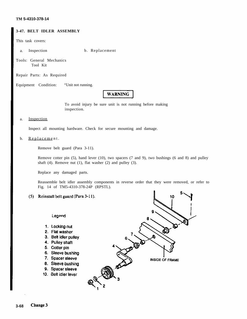
Para 3-11
TM 5-4310-378-14
3-47. BELT IDLER ASSEMBLY
This task covers:
a. Inspection b. Replacement
Tools: General MechanicsTool Kit
Repair Parts: As Required
Equipment Condition:
a.
b.
Inspection
“Unit not running.
To avoid injury be sure unit is not running before makinginspection.
Inspect all mounting hardware. Check for secure mounting and damage.
R e p l a c e m e n t .
Remove belt guard (Para 3-11).
Remove cotter pin (5), hand lever (10), two spacers (7 and 9), two bushings (6 and 8) and pulleyshaft (4). Remove nut (1), flat washer (2) and pulley (3).
Replace any damaged parts.
Reassemble belt idler assembly components in reverse order that they were removed, or refer toFig. 14 of TM5-4310-378-24P (RPSTL).
3-68

TM 5-4310-378-14
Section VII. PREPARATION FOR STORAGE OR SHIPMENT
3-48. GENERAL
This section provides instructions for preparation of the compressor assembly for storage or shipment.
3-49.
a.
b.
c.
3-50.
a.
b.
c.
d.
e.
ADMINISTRATIVE STORAGE
Placement of equipment in administrative storage should be for short periods of time when a shortage ofmaintenance effort exists. Items should be in mission-readiness within 24 hours or within the time factorsas determined by the directing authority. During the storage period, appropriate maintenance records willbe kept.
Before placing equipment in administrative storage, current maintenance services and Preventive Mainte-nance Checks and Services (PMCS) should be completed, shortcomings and deficiencies should be cor-rected and all modification work orders (MWOs) should be applied.
Storage site selection. Inside storage is preferred for items selected for administrative storage. If insidestorage is not available, trucks, vans, conex containers and other containers maybe used.
PACKING AND SHIPPING
Drain fuel tank into a suitable container.
Drain oil from compressor and engine crankcases.
Fill engine crankcase with preserving oil (Appendix E, item 6). Fill compressor crankcase with oil(Appendix E, item 5).
Use shipping plugs, closures, or sealing tape to cover all openings in the compressor assembly.
Attach to compressor all forms, tags, and records applicable to the units.
Change 3 3-69/(3-70 blank)


TM 5-4310-378-14
CHAPTER 4
INTERMEDIATE DIRECT SUPPORT MAINTENANCE INSTRUCTIONS
SECTION I. TROUBLESHOOTING
4-1. GENERAL.
a . The table in this section lists the common malfunctions which you may find during theoperat ion or maintenance of the air compressor or i ts components . You shouldperform the test / inspect ion and correct ive maintenance in the order l is ted.
b . This manual cannot list all malfunctions that may occur, nor all test or inspectionsand corrective actions. If a malfunction is not listed or it is not corrected by thel is ted correct ive act ion, not i fy your supervisor .
4-1

TM 5-4310-378-14
Table 4-1. Intermediate Direct Support Maintenance Troubleshooting.
MALFUNCTIONTEST OR INSPECTION
CORRECTIVE ACTION
1. SEVERE VIBRATION.
2.
Disassemble and inspect crankshaft and bearing.
Replace defective crankshaft or bearings.
ABNORMAL NOISE.
Step 1. Check for loose valve assembly.Repeat for other two cylinders.
If valve is loose, tighten valve pushcover (5). Install new head gasket (4),head (3), eight washers (2), and fourbolts (1). Tighten all four bolts (1)securely. Reconnect piping.
Step 2. Check for signs of piston strikinghead.
If piston was striking head, installtwo new gaskets (4), head (3), eightflat washers (2) and four bolts (l).
Tighten all four bolts securely.Reconnect piping.
If the above corrective actions do notcorrect the malfunction, notify yoursupervisor.
4-2 Change 3

TM 5-4310-378-14
Table 4-1. Intermediate Direct Support Maintenance Troubleshooting (Continued)
MALFUNCTIONTEST OR INSPECTION
CORRECTIVE ACTION
3. LITTLE OR NO AIR PRESSURE BUILDUP.
Step 1. Check cylinders, pistons, andrings for damage.
If valve is loose, tightenvalve push cover (5). Installnew head gasket (4), head (3),four bolts (l), and eightwashers (2) . Tighten al l fourbo l t s s ecu re ly . Reconnec tpiping.
If valve assembly is dirty,clean valve assembly. Instal lnew head gasket (4), head (3),four bolts (l), and eightwashers (2). Tighten all fourbolts (1) securely.Reconnect piping.
If head gasket is defective,replace head gasket . Instal lnew head gasket (4), head (3),four bolts (l), and eightwashers (2). Tighten all fourbolts (1) securely.Reconnect piping.
If the above steps do notco r r ec t t he ma l func t ion ,notify your supervisor.
4-3

TM 5-4310-378-14
Table 4-1. Intermediate Direct Support Maintenance Troubleshooting (Continued)
MALFUNCTIONTEST OR INSPECTION
CORRECTIVE ACTION
ENGINE DIFFICULT TO START.
Step 1.
Step 2.
Step 3.
Step 4.
Step 5.
Step 6.
Step 7.
Step 8.
Fuel tank empty or fuel cock closed.
Fill fuel tank and/or open fuel cock.
Incorrect choke set t ing, especial ly if
Adjust choke.
engine is cold.
Carburetor flooded by too much choking, especially if engine is hot.
Adjust choke.
Loss of compression due to dry cylinder.
Restore compression. Remove spark plug. Pour approximately one ounce ofengine oil into cylinder and crank engine a few times to distribute oil. Replacespark plug.
Loose or broken spark plug.
Tighten or replace spark plug.
Damaged cylinder head gasket or loose cylinder head.
Replace damaged gasket , and/or t ighten cyl inder head.
Broken ignition wire causing short circuits.
Replace broken ignition wires.
Defect ive igni t ion coi l .
Replace defect ive ignit ion coi l .
4 - 4

TM 5-4310-378-14
Table 4-1. Intermediate Direct Support Maintenance Troubleshooting (Continued)
MALFUNCTIONTEST OR INSPECTION
CORRECTIVE ACTION
5. ENGINE STOPS.
Step 1. Fuel tank empty. Water, dirt or gum in gasoline.
Fill fuel tank or clean fuel tank.
Step 2. Gasoline vaporized in fuel lines due to excessive heat around engine (vapor lock).
Correct any engine shrouding problems (missing or loose shrouds).
6. ENGINE OVERHEATS.
Step 1.
Step 2.
Step 3.
Oil level low.
Refill crankcase immediately.
Restricted air circulation or shroud removed.
Inspect air passages and clear obstructions.
Replace shroud.
Restricted exhaust.
Clear exhaust obstruction.
Change 4 4-5

TM 5-4310-378-14
Section ll. Maintenance Procedures.
4-2. This section contains those maintenance procedures that are the responsibility of Intermediate Direct SupportMaintenance.
4-3. COMPRESSOR ASSEMBLYThis task covers:
Repair
Tools: 3/8-in. Wrench1/2-in. Wrench5/8-in. Wrench11/16-in. Wrench3/4-in. Wrench15/16-in. Wrench13-mm Wrench21-mm Wrench23-mm Wrench
Materials: Brush, Cleaning (Appendix E, item 1)Rag, Wiping (Appendix E, item 3)Solvent, Dry Cleaning (Appendix E, item 2)
Equipment Condition: Ignition switch pushed in (Table 2-1, 8).Compressor removed from hand truck (para 3-14).
Compressor repair is limited to replacing defective parts.
*U.S. GOVERNMENT PRINTING OFFICE: 1993 - 755-0218/80206
4 - 6

TM 5-4310-378-14
4-4. COMPRESSOR CYLINDER HEADS AND VALVES
This task covers:
a . I n s p e c t i o n b .
Tools : 13-mm Wrench21-mm Wrench11/16-in. WrenchPliers , Snap-ring
Mate r i a l s : Head Gasket (3
R e p l a c e m e n t c . Repa i r
each )First Stage Outlet Valve Packing (2 each)Second Stage Outlet Valve PackingBrush, Cleaning (Appendix E, item 1)Rag, Wiping (Appendix E, item 3)Solvent, Dry cleaning (Appendix E, item 2).
Equipment Condi t ion: Compressor removed from handtruck and placed on work bench(para 3-14).Tubes removed from compressor (para 3-15).
a . I n spec t i on .
Dry Cleaning Solvent(Stoddard Solvent)
P-D-680
l Combustible - do not use near open flames, near weldingareas, or on hot surfaces.
l Prolonged or repeated contact of skin with liquid can causedermati t is . Repeated inhalat ion of vapor can i rr i ta te noseand throat and can cause dizziness.
l If any liquid contacts skin or eyes, immediately flushaffected area thoroughly with water . Remove solvent-saturated clothing. I f vapors cause dizziness , go to fresha i r .
l When handling liquid or when applying it in an air-exhausted, par t ia l ly covered tank, wear approved gloves.
l When handling liquid or when applying it at an unexhausted,uncovered tank or workbench, wear approved respira tor ,goggles, and gloves.
(1) Use brush, rag, and solvent as necessary to inspect cylinder heads and valves.
(2) Inspect for loose or missing mounting bolts and damage to cylinder heads.
4-7

TM 5-4310-378-14
b. R e p l a c e m e n t .
NOTE
The upper first stagecylinder head has thebelt guard bracket andstrut secured by speciallength head bolts.
( 1 ) R e m o v a l
(a) Remove four bol ts ( l ) . I fremoving the upper f i rs t s tagecyl inder head, remove the bel tguard bracket and s t rut .
(b) Remove head (2) and gasket(3) . Discard gasket .
(c) Remove outlet valve pushcover (4), packing (5), spring(6) and plate (7) from head(8). Discard packing (5).
(d) Remove snap ring (9), valvereceiver (10), spring (11), andvalve plate (12) from head (8).
(2 ) In s t a l l a t i on
(a ) Ob ta in r ep l acemen t pa r t s andinstall valve plate (12), spring(11), valve receiver (10), andsnap ring (9) to head (8).
( b ) Ob ta in r ep l acemen t pa r t s andinstall valve plate (7), spring(6), new packing (5), and pushcover (4).
(c) Install new head gasket (3) and
NOTE
The upper first stagecylinder head has beltguard bracket and s t rutsecured by speciallength head bolts.
4 - 8
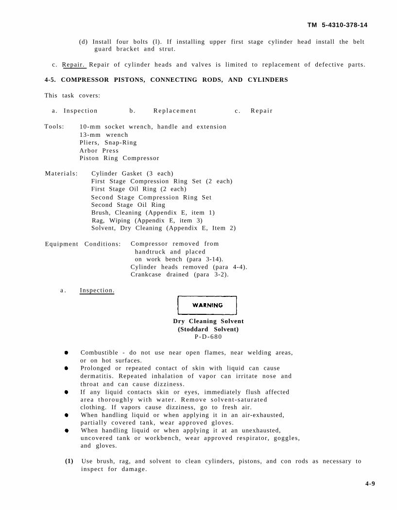
TM 5-4310-378-14
(d) Install four bolts (l). If installing upper first stage cylinder head install the beltguard bracket and s t rut .
c . Repair . Repair of cyl inder heads and valves is l imited to replacement of defect ive parts .
4-5. COMPRESSOR PISTONS, CONNECTING RODS, AND CYLINDERS
This task covers:
a . I n spec t ion b . R e p l a c e m e n t c . R e p a i r
Tools : 10-mm socket wrench, handle and extension13-mm wrenchPliers, Snap-RingArbor PressPiston Ring Compressor
Mate r i a l s : Cylinder Gasket (3 each)First Stage Compression Ring Set (2 each)First Stage Oil Ring (2 each)Second Stage Compression Ring SetSecond Stage Oil RingBrush, Cleaning (Appendix E, item 1)Rag, Wiping (Appendix E, item 3)Solvent, Dry Cleaning (Appendix E, Item 2)
Equipment Condi t ions: Compressor removed f romhandtruck and placedon work bench (para 3-14).
Cylinder heads removed (para 4-4).Crankcase drained (para 3-2).
a . Inspect ion.
Dry Cleaning Solvent(Stoddard Solvent)
P - D - 6 8 0
(1)
Combustible - do not use near open flames, near welding areas,or on hot surfaces.Prolonged or repeated contact of skin with liquid can causedermati t is . Repeated inhalat ion of vapor can irr i tate nose andthroat and can cause dizziness .If any liquid contacts skin or eyes, immediately flush affecteda rea t ho rough ly w i th wa te r . Remove so lven t - s a tu r a t edclothing. If vapors cause dizziness, go to fresh air.When handling liquid or when applying it in an air-exhausted,par t ia l ly covered tank, wear approved gloves.When handling liquid or when applying it at an unexhausted,uncovered tank or workbench, wear approved respira tor , goggles ,and gloves.
Use brush, rag, and solvent to clean cylinders, pistons, and con rods as necessary toinspect for damage.
4-9
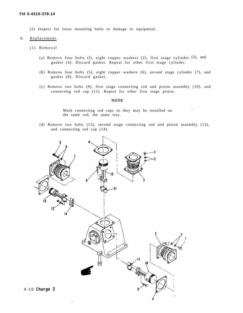
Change 2
TM 5-4310-378-14
(2) Inspect for loose mounting bolts or damage to equipment.
b. R e p l a c e m e n t .
( 1 ) R e m o v a l
(a) Remove four bol ts ( l ) , e ight copper washers (2) , f i rs t s tage cyl indergasket (4) . Discard gasket . Repeat for other f i rs t s tage cyl inder .
(3), and
(b) Remove four bolts (5), eight copper washers (6), second stage cylinder (7), andgasket (8) . Discard gasket .
(c) Remove two bolts (9), first stage connecting rod and piston assembly (10), andconnecting rod cap (11). Repeat for other first stage piston.
NOTE
Mark connecting rod caps so they may be installed on.
the same rod, the same way.
(d) Remove two bolts (12), second stage connecting rod and piston assembly (13),and connecting rod cap (14).
4 - 1 0

TM 5-4310-378-14
(e) Repair of the piston and connecting rod assemblies is as follows.
1)
2)
3)
4)
5)
6)
7)
8)
(2) Installation
(a)
(b)
(c)
(d)
(e)
Carefully remove both compression rings (1) and the oil ring (2). Discardthe rings.
Remove both snap rings (3) and using an arbor press, press out the pistonpin (4).
Separate the piston (5) from the connecting rod (6).
Obtain replacement parts.
Place piston (5) into position on connecting rod (6) and install piston pin (4)into position using an arbor press.
Install two snap rings (3).
Carefully install a new oil ring (2).
Carefully install two new compression rings (1).
Install second stage connecting rod and piston assembly (l), connecting rod cap(2), and secure with two bolts (3). Be sure that cap is installed in the originalposition.
Install first stage connecting rod and piston assembly (4), connecting rod cap (5),and secure with two bolts (6). Be sure that cap is installed in the originalposition. Repeat for other first stage connecting rod and piston assembly.
Install new gasket (7) into position.
Carefully install cylinder (8) over connecting rod and piston assembly. Securewith eight copper washers (9) and four bolts (10).
Install gasket (11) into position.
4-11

TM 5-4310-378-14
( f ) Careful ly insta l l cyl inder (12) over connect ing rod and pis ton assembly. Securewith eight copper washers (13) and four bolts (14). Repeat for other first stagecyl inder .
c . Repair . Repair of pis tons, connect ing rods, and cyl inders is l imited to replacement ofdefective parts.
4-12 Change 2

TM 5-4310-378-14
4-6. COMPRESSOR CRANKSHAFT, BEARINGS, OIL SEALS, AND CRANKCASE
This task covers:
a . I n s p e c t i o n b . R e p l a c e m e n t c . R e p a i r
Tools : 13-mm WrenchSlip-Joint PliersSmall Pipe Wrench
Mate r i a l s : Rear Bearing Cover PackingFront Bearing Cover PackingFront Oil SealOil Sight Gage SealBrush, Cleaning (Appendix E, item 1)Rag, Wiping (Appendix E, item 3)Solvent, Dry Cleaning (Appendix E, item 2)
Equipment Condi t ions: Compressor removed from handtruck and placed on work bench(para 3-14).
Cylinder heads, cylinders, pistons and connecting rods removed(para 4-4 and 4-5).
Crankcase drained (para 3-2).Flywheel removed (para 3-19).
a. I n s p e c t i o n .
Dry Cleaning Solvent(Stoddard Solvent)
P-D-680
Combustible - do not use near open flames, near weldingareas, or on hot surfaces.Prolonged or repeated contact of skin with liquid can causedermati t is . Repeated inhalat ion of vapor can i rr i ta te noseand throat and can cause dizziness.If any liquid contacts skin or eyes, immediately flush affecteda rea t ho rough ly w i th wa te r . Remove so lven t - s a tu r a t edclothing. If vapors cause dizziness, go to fresh air.When handling liquid or when applying it in an air-exhausted,par t ia l ly covered tank, wear approved gloves.When handling liquid or when applying it at an unexhausted,uncovered tank or workbench, wear approved respira tor ,goggles, and gloves.
(1) Use brush, rag, and solvent to clean crankshaft and crankcase as necessary to inspectf o r d a m a g e .
(2) Inspect for loose mounting bolts or damage to equipment.
4-13

TM 5-4310-378-14
b. R e p l a c e m e n t .
( 1 ) R e m o v a l
(a)
(b)
(c)
(d)
(e)
(f)
(g)
(h)
Remove four bolts (l), four washers (2), front bearing cover (3), and frontbear ing gasket (4) . Discard gasket .
Remove crankshaf t (5) .
Remove bearing (6) and bearing seal (7).
Remove four bolts (8), four washers (9), rear bearing cover (10), and gasket(11) . Discard gasket .
R e m o v e
R e m o v e
R e m o v e
R e m o v e
bearing (12).
oil sight gage (13) and oil sight gage seal (14).
oil drain cap (15) from crankcase (16).
all buildup of dirt, grease, etc., by wiping with a clean rag (Appendix E,item 3).
4-14 Change 2

TM 5-4310-378-14
TM 5-4130-378-14
(f)
(g)
(h)
Obtain replacement par ts as required.
Install oil drain cap (1) to crankcase (2).
(2 ) In s t a l l a t i on
(a)
(b)
(c)
(d)
(e)
Install oil sight gage seal (3) and oil sight gage (4).
Install bearing (5).
Install new gasket (6), rear bearing cover (7), four copper washers (8), and fourbolts (9).
Install new bearing seal (10) and bearing (11).
Install crankshaft (12).
Install new gasket (13), front bearing cover (14), four washers (15), and fourbolts (16).
Repair of crankshaft , bearings, oi l seals , and crankcase is l imited to replacementc . R e p a i r .of defect ive parts .
Change 2 4-15

TM 5-4310-378-14
4-7. ENGINE ASSEMBLY
This task covers:
a . Repa i r
Mate r i a l s : Brush, Cleaning (Appendix E, item 1)Rag, Wiping (Appendix E, item 3)Solvent, Dry Cleaning (Appendix E, item 2)
Equipment Condi t ion: Engine removed from handtruck and placed on work bench (para 3-21).
R e p a i r
Dry Cleaning Solvent(Stoddard Solvent)
P-D-680
Combustible - do not use near open flames, near weldingareas, or on hot surfaces.Prolonged or repeated contact of skin with liquid can causedermati t is . Repeated inhalat ion of vapor can i rr i ta te noseand throat and can cause dizziness.If any liquid contacts skin or eyes, immediately flushaffected area thoroughly with water . Remove solvent-saturated clothing. If vapors cause dizziness, go to fresha i r .When handling liquid or when applying it in an air-exhausted, par t ia l ly covered tank, wear approved gloves.When handling liquid or when applying it at an unexhausted,uncovered tank or workbench, wear approved respira tor ,goggles, and gloves.
(1) Use brush, rag, and solvent as necessary to clean engine assembly so that requiredrepair work can be performed.
(2) Repair of engine assembly is l imited to replacement of defect ive parts . Refer toparagraphs 3-21 through 3-35 for specific parts to be replaced.
4-16

TM 5-4310-378-14
4-8. ENGINE GOVERNOR AND CONTROL ASSEMBLY
This task covers;
a . Adjustment b. Replacement
Tools: Materials:10-mm Wrench Governor LeverRevolution Counter Clamp Screw and Nut
Governor Spring and Rod Set
Equipment Condition: Engine removed from handtruck (para 3-21)
W A R N I N G
Keep fingers and hand away from rotating pulley to pre-vent injury to personnel.
a. Adjustment.
(1) Loosen locknut (1) on adjusting screw (2).
(2) Operate engine without load and push control lever (3) in a counterclockwise direction so thatadjusting screw (2) is against stop lug (4).
(3) Place a revolution counter against the end of the crankshaft and rotate the adjusting screw (2) toobtain 2850 RPM. Righten locknut(1).
Change 3 4-16.1/(4-16.2 blank)


TM 5-4310-378-14
4-8. ENGINE GOVERNOR AND CONTROL ASSEMBLY (cont.)
b. Replacement.
(1) Removal
(a)
(b)
(c)
and governor rod (3).
Remove clamp screw (4) andnut (5).
Slide governor lever (6) from
Remove governor spring androd set consisting of: governorrod spring (1), governor spring (2),
governor shaft (7).
(2) Installation
(a)
(b)
(c)
(d)
Obtain replacement parts.
Install governor lever (6) ongovernor shaft (7); do nottighten clamp screw (4) andnut (5).
Install governor rod (3), gov-ernor spring (2), and governorrod spring ( 1).
Adjust govenor and controlassembly per Chapter 3, para-graph 3-31.
Change 3 4-17

TM 5-4310-378-14
4-9. AIR TANK
This task covers:
a . R e p l a c e m e n t
Tools : 7/16-in. Wrench
Mate r i a l s : Brush, Cleaning (Appendix E, item 1)Rag, Wiping (Appendix E, item 3)Solvent, Dry cleaning (Appendix E, item 2).Air Tank Strap Assemblies.
Equipment Condi t ion: Ignition switch pushed in (Table 2-1, 8).
a .
All parts removed from air tank: Inflatorgage, hose, pressure gage, tank relief valve, pilot valve, drain valve,af tercooler assembly, and al l f i t t ings for at tachment .
R e p l a c e m e n t .
(1) Remove two nuts (1), and two washers (2) securing strap assemblies (3).
(2) Remove ai r tank (4) f rom handtruck.
Dry Cleaning Solvent(Stoddard Solvent)
P-D-680
Combustible - do not use near open flames, nearareas. or on hot surfaces.
welding
Prolonged or repeated contact of skin with liquid can causedermati t is . Repeated inhalat ion of vapor can i rr i ta te noseand throat and can cause dizziness.If any liquid contacts skin or eyes, immediately flush affectedarea thoroughly with water . Remove solvent-saturatedclothing. If vapors cause dizziness, go to fresh air.When handling liquid or when applying it in an air-exhausted,par t ia l ly covered tank, wear approved gloves.When handling liquid or when applying it at an unexhausted,uncovered tank or workbench, wear approved respira tor ,
goggles, and gloves.
(3) Use brush, rag, and solvent as necessary to clean hand truck and straps.
(4) Place air tank (4) on handtruck with pilot valve boss (5) towards compressor and drainvalve boss down.
(5) Secure air tank (4) with strap assemblies (3), two washers (2), and two nuts (l).
(6) Instal l a l l the hardware removed at the s tar t of this procedure.
4 - 1 8

TM 5-4310-378-14
Change 3 4-9/(4-20 blank)


TM 5-4310-378-14
CHAPTER 5
INTERMEDIATE GENERAL SUPPORT MAINTENANCE INSTRUCTIONS
SECTION I. TROUBLESHOOTING
5-1. TROUBLESHOOTING
a . Table 5-1 contains t roubleshoot ing information for locat ing and correct ing most ofthe operat ing t roubles which are the responsibi l i ty of Intermediate General SupportMaintenance. Each malfunction for an individual component, unit, or system is followed by alist of tests or inspections which will help you to determine probable causes and correctiveact ions to take. Perform the tests / inspect ions and correct ive act ions in the order l is ted.
b . This manual cannot list all malfunctions that may occur, nor all tests or inspectionsand corrective actions. If a malfunction is not listed or is not corrected by listed correctiveactions, notify your supervisor.
c . Only those funct ions within the scope of general support maintenance are l is ted. Fortroubleshoot ing procedures within the scope of operator /crew maintenance, refer to table 3-1.For t roubleshoot ing procedures within the scope of organizat ional maintenance, refer to table4-3 .
Table 5-1. Intermediate General Support Maintenance Troubleshooting
MALFUNCTIONTEST OR INSPECTION
CORRECTIVE ACTION
1.
2.
COMPRESSOR FAILS TO OPERATE.
Step 1. With engine running and drive belts operating the compressor, air is not beingp re s su r i zed .
R e p l a c e c o m p r e s s o r .
ENGINE FAILS TO OPERATE, OR OPERATES WITH EXCESSIVE NOISE.
S t e p
S t e p
1. Check for fuel in cylinder, compression in the cylinder, spark (strong andproperly t imed) .
R e p l a c e e n g i n e .
2. Check for excessive end play in the crankshaft.
R e p l a c e e n g i n e .
5-1

TM 5-4310-378-14
Section II. Maintenance Procedures.
5-2. AIR COMPRESSOR OVERHAUL
This task covers:
a . O v e r h a u l
Tools :13-mm wrench3/8-inch wrench19-mm wrench21-mm wrenchGear PullerPliers, common24-mm wrenchPliers, Snap-Ring
Mate r i a l : Rear Bearing Cover PackingFront Bearing Cover PackingFront Oil SealOil Sight Gage SealHead Gasket (3 each)First Stage Outlet Valve Packing (2 each)Second Stage Outlet Valve PackingCylinder Gasket. (3 each)First Stage Compression Ring Set (2 each)First Stage Oil Ring (2 each)Second Stage Compression Ring SetSecond Stage Oil RingBrush, Cleaning (Appendix E, item 1)Rag, Wiping (Appendix E, item 3)Solvent, Dry cleaning (Appendix E, item 2).
Equipment Condi t ion: Compressor removed from handtruckand placed on work bench (para 3-14).Tube assemblies removed (para 3-15).
a. O v e r h a u l .
(1) Remove four bol ts ( l ) , and eightwashers (2).
(2) Remove head (3) and gasket (4).Discard gasket .
5 - 2

TM 5-4310-378-14
(3) Remove outlet valve push cover(l), packing (2), spring (3), andvalve plate (4) from head (5).Discard packing (2).
(4) Remove four bolts (l), eightcopper washers (2), first stagecylinder (3), and gasket (4).Discard gasket. Repeat for otherfirst stage cylinder.
(5) Remove four bolts (5), eightcopper washers (6) second stagecylinder (7), and gasket (8).Discard gasket.
5-3

TM 5-4310-378-14
(6)
(7)
(8)
(9)
(l0)
(11)
(12)
Remove two bolts (9), first stage connecting rod and piston assembly(l0), andconnecting rod cap (11). Repeat for other first stage piston.
Remove two bolts (12), second stage connecting rod and piston assembly (13), andconnecting rod cap (14).
Remove four bolts (15), four washers (16), front bearing cover (17), and front bearinggasket (18). Discard gasket.
Remove crankshaft (19).
Remove bearing (20) and bearing seal (21).
Remove four bolts (22), four washers (23), rear bearing cover (24), and gasket (25).Discard gasket.
Remove bearing (26).
5-4 Change 2
TM 5-4310-378-14
(13) Remove oil sight gage (27) and oil sight gage seal (28).
(14) Remove oil drain plug (29) from crankcase (30).
(15) Remove al l bui ldup of dir t , grease, e tc . , by wiping with a clean rag (Appendix E,item 3).
Dry Cleaning Solvent(Stoddard Solvent)
P-D-680
Combustible - do not use near open flames, near welding areas, oron hot surfaces.Prolonged or repeated contact of skin with liquid can causedermati t is . Repeated inhalat ion of vapor can irr i tate nose andthroat and can cause dizziness .If any liquid contacts skin or eyes, immediately flush affected areathoroughly with water . Remove so lven t - s a tu r a t ed c lo th ing . I fvapors cause dizziness, go to fresh air.When handling liquid or when applying it in an air-exhausted,par t ia l ly covered tank, wear approved gloves.When handling liquid or when applying it at an unexhausted,uncovered tank or workbench, wear approved respira tor , goggles ,and gloves.
(16) Clean using a clean, soft cloth (Appendix E, item 3) or a medium bristle brush(Appendix E, item 1) and cleaning solvent (Appendix E, item 2).
( 1 7 ) I n s p e c t
(a) for miss ing or damaged hardware.
(b) cyl inders for damage and wear .
(c) pis ton and connect ing rod assembly
(d) crankshaf t for damage and wear .
( e ) c r ankcase fo r damage .
( f ) f ront bear ing cover for damage.
(g) rear bear ing cover for damage.
for damage and wear.
(h) both bear ings for damage and wear .
(18) Repair of the air compressor (except for the piston and connecting rod assemblies) isl imited to the replacement of defect ive parts .
5-5
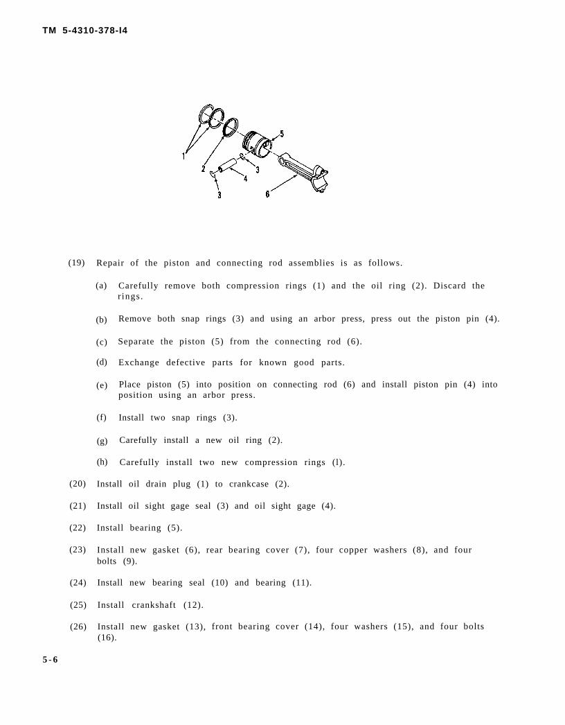
TM 5-4310-378-I4
(19)
(20)
(21)
(22)
(23)
(24)
(25)
(26)
5 - 6
Repair of the piston and connecting rod assemblies is as follows.
(a)
(b)
(c)
(d)
(e)
(f)
(g)
(h)
Carefully remove both compression rings (1) and the oil ring (2). Discard ther ings .
Remove both snap rings (3) and using an arbor press, press out the piston pin (4).
Separate the piston (5) from the connecting rod (6).
Exchange defective parts for known good parts.
Place piston (5) into position on connecting rod (6) and install piston pin (4) intoposition using an arbor press.
Install two snap rings (3).
Carefully install a new oil ring (2).
Carefully install two new compression rings (l).
Install oil drain plug (1) to crankcase (2).
Install oil sight gage seal (3) and oil sight gage (4).
Install bearing (5).
Install new gasket (6), rear bearing cover (7), four copper washers (8), and fourbolts (9).
Install new bearing seal (10) and bearing (11).
Install crankshaft (12).
Install new gasket (13),(16).
front bearing cover (14), four washers (15), and four bolts

TM 5-4310-378-14
(27) Install second stage connecting rod and piston assembly (17), connecting rod cap (18), and securewith two bolts (19). Be sure that cap is installed in the original position.
(28) Install first stage connecting rod and piston assembly (20), connecting rod cap (21), and secure withtwo bolts (22). Be sure that cap is installed in the original position. Repeat for the other first stageconnecting rod and piston assembly,
(29) Install new gasket (23) into position.
(30) Carefully install cylinder (24) over connecting rod and piston assembly. Secure with eight copperwashers (25) and four bolts (26).
(31 ) Install gasket (27) into position.
Change 3 5-7

TM 5-4310-378-14
(32) Carefully install cylinder (28) over con-necting rod and piston assembly. Securewith eight copper washers (29) and fourbolts (30). Repeat these steps for the otherfirst stage cylinder.
(33) Install flywheel.
(34) Install cylinder heads.
(35) Install valve plate (1), spring (2), valvereceiver (3), and snap ring (4) to head (5).
(36) Install valve plate (6), spring (7), newpacking (8), and push cover (9).
(37) Install new head gasket and head.
(38) Install eight washers and four bolts.
5-8 Change 3

TM 5-4310-378-14
APPENDIX A
REFERENCES
A-1. SCOPE
This appendix lists all forms, field manuals, and technical manuals referenced in this manual.
A-2. FORMS
Recommended changes to publications and Blank Forms
Quality Deficiency Report
A-3. TECHNICAL MANUALS
The Army Maintenance Management System (TAMMS)
Procedures for Destruction of Equipmentto Prevent Enemy Use.
Unit, Intermediate Direct Support and IntermediateGeneral Support Maintenance Repair Parts and SpecialTools List.
Inspection and Test of Air and Other Gas Compressors
DA 2028
SF 368
DA PAM 348-750
TM 750-244-3
TM 5-4310-378-24P
TB 43-0151
Change 3 A-1/(A-2 blank)


TM 5-4310-378-14
APPENDIX B
MAINTENANCE ALLOCATION CHART
SECTION I. INTRODUCTION
B-1. GENERAL
a . This section provides a general explanation of all maintenance and repair functionsauthorized at var ious maintenance categories .
b . The Maintenance Allocation Chart (MAC) in section II designates overallresponsibility for the performance of maintenance functions on the identified end item orcomponent . The implementat ion of the maintenance funct ions upon the end i tem or componentwil l be consis tent with the assigned maintenance funct ions.
c. Section III lists the special tools and test equipment required for each maintenancefunction as referenced from section II.
d. Sect ion IV contains supplemental instruct ions and explanatory notes for a part icularmaintenance funct ion.
B-2. MAINTENANCE FUNCTIONS
Maintenance functions will be limited to and defined as follows:
a . Inspect . To determine the serviceabi l i ty of an i tem by comparing i ts physical ,mechanical , and/or electr ical character is t ics with establ ished standards through examinat ion.
b . Test . To verify serviceabi l i ty by measuring the mechanical or electr icalcharacter is t ics of an i tem and comparing those character is t ics with prescr ibed s tandards.
c . Service. Operat ions required periodical ly to keep an i tem in proper operat ingcondition, i.e., to clean (includes decontaminate, when required), to preserve, to drain, to paint,or to replenish fuel, lubricants, chemical fluids, or gases.
d. Adjust. To maintain, within prescribed limits, by bringing into proper or exactposi t ion, or by set t ing the operat ing character is t ics to specif ied parameters .
e . A l i g n . To adjust specified variable elements of an item to bring about optimum ord e s i r e d p e r f o r m a n c e .
f . Calibrate. To determine and cause corrections to be made or to be adjusted oninstruments or tes t , measuring, and diagnost ic equipments used in precis ion measurement .Consists of comparisons of two instruments, one of which is a certified standard of knownaccuracy, to detect and adjust any discrepancy in the accuracy of the instrument beingc o m p a r e d .
Install. The act of emplacing, seating, or fixing into position an item, part, or module(component or assembly) in a manner to allow the proper functioning of an equipment or system.
B-1

TM 5-4310-378-14
h. Replace. The act of substituting of a serviceable like type part, subassembly, ormodule (component or assembly) for an unserviceable counterpart.
i. Repair. The application of maintenance services or other maintenance actions torestore serviceability to an item by correcting specific damage, fault, malfunction, or failure ina part, subassembly, module (component or assembly), end item, or system.
j. Overhaul. That maintenance effort (service/action) necessary to restore an item to acompletely serviceable/operational condition as prescribed by maintenance standards inappropriate technical publications (i.e., DMWR). Overhaul is normally the highest degree ofmaintenance performed by the Army. Overhaul does not normally return an item to like newcondition.
k. Rebuild. Consists of those services/actions necessary for the restoration ofunserviceable equipment to a like new condition in accordance with original manufacturingstandards. Rebuild is the highest degree of materiel maintenance applied to Army equipment.The rebuild operation includes the act of returning to zero those age measurements(hours/miles, etc.) considered in classifying Army equipments/components.
B-3. EXPLANATION OF COLUMNS IN THE MAC, SECTION II
a. Column 1. Group Number. Column 1 lists functional group code numbers, thepurpose of which is to identify components, assemblies, subassemblies, and modules with thenext higher assembly.
b. Column 2. Component/Assembly. Column 2 contains the names of components,assemblies, subassemblies, and modules for which maintenance is authorized.
c.the item
d.figure in
Column 3. Maintenance Function. Column 3 lists the functions to be performed onlisted in Column 2. (For detailed explanation of these functions, see paragraph B-2.)
Column 4. Maintenance Category. Column 4 specifies, by the listing of a work timethe appropriate subcolumn(s), the lowest level of maintenance authorized to perform
the function listed in Column 3. This figure represents the active time required to perform thatmaintenance function at the indicated category of maintenance. If the number or complexity ofthe tasks within the listed maintenance function vary at different maintenance categories,appropriate work time figure will be shown for each category. The work time figure representsthe average time required to restore an item (assembly, subassembly, component, module, enditem, or system) to a serviceable condition under typical field operating conditions. This timeincludes preparation time, troubleshooting time, and quality assurance/quality control time inaddition to the time required to perform the specific tasks identified for the maintenancefunctions authorized in the maintenance allocation chart. The symbol designations for thevarious maintenance categories are as follows:
c Operator or crew.o Organizational maintenance.F Direct support maintenance.H General support maintenance.D Depot maintenance.
Column 5. Tools and Equipment. Column 5 specifies by code those common tool sets(not individual tools) and special tools, TMDE, and support equipment required to perform thedesignated function.
B-2

TM 5-4310-378-14
f . Column 6. Remarks. This column shall, when applicable, contain a letter code, inalphabetic order, which shall be keyed to the remarks contained in Section IV.
B-4. EXPLANATION OF COLUMNS IN TOOL AND TEST EQUIPMENT REQUIREMENTS,SECTION III
a . Column 1. Reference Code. The tool and test equipment reference code correlateswith a code used in the MAC, Section II, Column 5.
b . Column 2. Maintenance Category. The lowest category of maintenance authorizedto use the tool or test equipment.
c. Column 3. Nomenclature. Name or ident i f icat ion of the tool or tes t equipment .
d . Column 4. National Stock Number. The National stock number of the tool or testequ ipmen t .
e. Column 5. Tool Number . The manufacturer’s par t number .
B-5. EXPLANATION OF COLUMNS IN REMARKS, SECTION IV
a . Column 1. Reference Code. The code recorded in column 6, Section II.
b . Column 2. Remarks. This column l is ts information pert inent to the maintenancefunction being performed as indicated in the MAC, Section II.
B-3

TM 5-4310-378-14
Section II. MAINTENANCE ALLOCATION CHARTFOR COMPRESSOR UNIT, RECIPROCATING SCFM 175PSI, GASOLINE
ENGINE DRIVEN, HAND TRUCK MOUNTED
(1)
GroupNumber
00
01
02
(2)
Component/Assembly
Compressor Unit,Reciprocating,
COMPRESSOR DRIVE
Guard Assembly, Belt
Belts, V, Matched Set
Pulley, Drive
COMPRESSORASSEMBLY
Tube Assembly
Interstage ReliefValve
Air Cleaner
Oil Filler Capand Sight Glass
Flywheel
Unloader Valves
Cylinder Head,Intake and ExhaustValves
(3)
MaintenanceFunction
InspectReplace
InspectReplace
InspectReplace
InspectReplaceRepairOverhaul
InspectReplace
InspectReplace
InspectReplace
InspectReplace
InspectReplace
InspectReplace
InspectReplaceRepair
(5)
Tools andEquipment
T1
T1T1
T1T1, T4
T1T1, T2T1, T3
T1T1
T1T1
T1
T1
TT1, T4
T1T1, T4
T1, T4T1, T4T1, T4
(6)
Remarks
B-4 Change 1

TM 5-4310-378-14
(1)
GroupNumber
03
Section II. MAINTENANCE ALLOCATION CHARTFOR COMPRESSOR UNIT. RECIPROCATING SCFM 175PSI, GASOLINE
ENGINE DRIVEN, HAND TRUCK MOUNTED
(2)
Component/Assembly
Pistons, ConnectingRods and CylinderBlock
Crankshaft,Bearings, Oil Sealsand Crankcase
ENGINE ASSEMBLY
Fuel Tank Assemblyand Fuel Filter
COOLING SYSTEM
Ducts, Covers,Baffles
Flywheel
IGNITIONCOMPONENTS
Coil
Switch, Ignition(Stop Button)
Spark Plug
(3)
MaintenanceFunction
InspectReplaceRepair
InspectReplaceRepair
InspectReplaceRepair
InspectServiceReplace
InspectReplace
InspectReplace
InspectTestReplace
InspectTestReplace
InspectServiceReplace
(5)
Tools andEquipment
T1, T2T1,T2T1,T2
T1,T2T1,T2T1,T2
T1T1,T2
T1,T4
T1,T4
T1T1,T4
T1T1,T4T1,T4
T1T1,T4T1,T4
T1T1,T4T1,T4
(6)
Remarks
Change 1 B-5

TM 5-4310-378-14
(1)
GroupNumber
Section II. MAINTENANCE ALLOCATION CHARTFOR COMPRESSOR UNIT, RECIPROCATING SCFM 175PSI, GASOLINE
ENGINE DRIVEN, HAND TRUCK MOUNTED
(2)
Component/Assembly
AIR CLEANERASSEMBLY
Element
CARBURETOR
Carburetor
ENGINE SPEEDGOVERNOR ANDCONTROLS
Governor
Governor RodAssembly
Governor ControlAssembly
Recoil StarterAssembly
Cylinder Headand Gasket
Oil Dipstickand Gasket
(3)
MaintenanceFunction
InspectServiceReplace
InspectServiceReplace
InspectServiceAdjustReplace
InspectAdjustReplace
InspectAdjustReplace
InspectAdjustReplace
InspectReplaceRepair
InspectService
InspectReplace
(5)
Tools andEquipment
T1T1 ,T4
T 1,T4T 1,T4T 1,T4T 1,T4
T 1,T4T 1,T2
T1T1 ,T4T1 ,T2
T1T1 ,T4T1 ,T2
T1 ,T4T1,T4
T1T1,T4
T1 ,T4
(6)
Remarks
B-6 Change 3

Group Number 06
TM 5-4310-378-14
GroupNumber
04
05
Section II. MAINTENANCE ALLOCATION CHARTFOR COMPRESSOR UNIT, RECIPROCATING SCFM 175PSI, GASOLINE
ENGINE DRIVEN, HAND TRUCK MOUNTED
(2)
Component/Assembly
AIR RECEIVERSYSTEM
AftercoolerAssembly
Safety Valve
Drain Valve
Pressure Gauge
Tank Relief Valve
Air Tank
AIR DISCHARGESYSTEM
Hoses
Inflator Gauge
HANDTRUCKASSEMBLY
Wheels
Tires and Tubes
Belt IdlerAssembly
(3)
MaintenanceFunction
InspectReplace
InspectReplace
InspectReplace
InspectReplace
InspectReplace
InspectReplace
InspectReplace
InspectReplace
InspectReplace
InspectServiceRepairReplace
InspectReplace
0.1
0.1
0.1
0.1
(4)Maintenance Level
0.10.3
0.10.2
0.2
0.10.1
0.2
0.1
0.2
0.2
0.20.3
0.10.10.20.4
0.10.4
0.5
(5)
Tools andEquipment
T1 ,T4
T1T1 ,T4
T1,T4
T1T1,T4
T1 ,T4
T1T1,T2
T1,T4
T1,T4
T1T1,T4
T1T1,T4T1,T4T1,T4
T1
(6)
Remarks
Change 3 B-7

TM 5-4310-378-14
SECTION III. TOOL AND TEST EQUIPMENT REQUIREMENTS FORCOMPRESSOR UNIT, RECIPROCATING SCFM 175PSI, GASOLINE
ENGINE DRIVEN, HAND TRUCK MOUNTED
(1)Reference
Code
T1
T2
(2)Maintenance
Level
c
F
H
o
c
o
F
(3)
Nomenclature
Tool Kit, General Mechanic,Automotive
Shop Set, Automotive Repair, FieldMaintenance, Basic
Shop Set, Machine: FieldMaintenance Heavy
Shop Equipment AutomotiveMaintenance and Repair Organiza-tion, Common NO 1
Tool Kit, General Mechanic,Automotive, Metric
Tool, OrganizationMaintenance, Metric
Tool Kit, Direct SupportMaintenance, Metric
SECTION IV. REMARKS
(4)National/NATO
Stock Number
5180-00-177-7033
4910-00-754-0705
3470-00-754-0738
4910-00-754-0654
5180-01-100-0963
5180-01-100-0964
5180-01-100-0965
(5)Tool
Number
Reference Code Remarks
B-8 Change 3

TM 5-4310-378-14
APPENDIX C
COMPONENT OF END lTEM AND BASIC ISSUE ITEMS LISTS
SECTION I. INTRODUCTION
C-1. SCOPE
This appendix lists components of end item and basic issue items for the air compressor to helpyou inventory i tems required for safe and eff ic ient operat ion.
C-2. GENERAL
The Components of End Item and Basic Issue Items Lists are divided into the following sections:
a . Section II. Components of End Item. This listing is for informational purposes only,and is not authori ty to requisi t ion replacements . These i tems are part of the end i tem, but areremoved and separately packaged for t ransportat ion or shipment . As par t of the end i tem,these items must be with the end item whenever it is issued or transferred between propertyaccounts . I l lustrat ions are furnished to assis t you in ident i fying the i tems.
b . Sect ion III . Basic Issue I tems. These are the minimum essential i tems required toplace the air compressor in operation, to operate it, and to perform emergency repairs.Although shipped separately packaged, BII must be with the air compressor during operation andwhenever i t is t ransferred between property accounts . The i l lustrat ions wil l assis t you withhard-to- ident i fy i tems. This manual is your authori ty to request / requis i t ion replacement BII ,based on TOE/MTOE authorization of the end item.
C-3. EXPLANATION OF COLUMNS
The following provides an explanation of columns found in the tabular listings:
a . Column (1) - Illustration Number (Illus Number). This column indicates the number ofthe illustration in which the item is shown.
b . Column (2) - National Stock Number. Indicates the National stock number assigned tothe item and will be used for requisitioning purposes.
c . Column (3) - Description. Indicates the Federal item name and, if required, aminimum descript ion to ident ify and locate the i tem. The last l ine for each i tem indicates theFSCM (in parentheses) followed by the part number.
d . Column (4) - Unit of Measure (U/M). Indicates the measure used in performing theactual operat ional /maintenance funct ion. This measure is expressed by a two-characteralphabetical abbreviation (e.g., ea, in, pr).
e . Column (5) - Quantity required (Qty rqr). Indicates the quantity of the itemauthorized to be used with/on the equipment .
C-1

(1)Illus
Number
1
2
SECTION II. COMPONENTS OF END ITEM
(2)National Stock
number
4910-00-204-2644
4720-01-179-5414
(3)DescriptionFSCM and Part number
INFLATOR GAGE(94894) 61-J2-1506
HOSE ASSEMBLY, DELIVERY(65473) GYAC5-PFS4-PFS4-600
(4)
U/M
EA
EA
( 5 )Qtyrqr
1
1
C-2 Change 3

C-3
TM 5-4310-378-14
SECTION III. BASIC ISSUE ITEMS
(1)Illus
Number
(2)National Stock
number
(3)DescriptionFSCM and Part number
(4)
U/M
(5)Qtyrqr


TM 5-4310-378-14
A P P E N D I X D
ADDITIONAL AUTHORIZATION LIST
SECTION I. INTRODUCTION
D-1. SCOPE
This appendix lists additional items you are authorized for the support of the air compressor.
D-2. GENERAL
This list identifies items that do not have to accompany the air compressor and that do not have to be turned inwith it. These items are all authorized to you by CTA, MTOE, TDA, or JTA.
D-3. EXPLANATION OF LISTING
National stock numbers, descriptions, and quantities are provided to help you identify and request the additionalitems you require to support this equipment. The items are listed in alphabetical sequence by item name underthe type document (i.e., CTA, MTOE, TDA, or JTA) which authorizes the item(s) to you.
(1)
NATIONALSTOCK
NUMBER
7510-00-889-3494
4240-00-664-2946
(2)
DESCRIPTION
FSCM & PART NUMBER USABLE ON CODE
BINDER, LOG BOOK
PROTECTOR, EAR
(3)
U/M
EA
EA
(4)
QTYAUTH
1
1
Change 3 D-1/(D-2 blank)


TM 5-4310-378-14
APPENDIX E
EXPENDABLE SUPPLIESA N D
MATERIALS LIST
SECTION I. INTRODUCTION
E-1. SCOPE This appendix lists expendable supplies and materials required to operate andmaintain the air compressor . These i tems are authorized by CTA 50-970, Expendable I tems(Except Medical Class V, Repair parts and Heraldic Items).
E-2. EXPLANATION OF COLUMNS
a . Column I - Item Number. This number is assigned to the entry in the listing and isreferenced in the narrative instructions of this manual to identify the material (e.g., “Use drycleaning solvent, item I, App E”).
b . Column 2- Level . This column identif ies the lowest level of maintenance authorizedto use the item listed.
. . . . O p e r a t o r / C r e w
c . Column 3- National Stock Number. This column ident if ies the National StockNumber assisgned to the item. The National Stock Number should be used to request orrequisi t ion the i tem.
d . Column 4- Descript ion. This column indicates the Federal i tem name and, i frequired, a description of the item. The last line indicates the Federal Supply Code forManufacturer (FSCM) in parentheses followed by the part number.
e. Column 5- Unit of Measure (U/M). This column indicates the measure used inperforming the actual maintenance funct ion. This measure is expressed by a two characteralphabetical abbreviation (e.g., ea in., pr). If the unit of measure differs from the unit of issue,request or requisition the lowest unit of issue that will satisfy the requirement.
E-1

TM 5-4310-378-14
(1)
ItemNo.
1
2
3
4
5
6
7
8
9
SECTION II. EXPENDABLE SUPPLIES AND MATERIALS LIST
(2)
Level
c
c
c
c
c
c
c
c
c
(3)National
StockNumber
7920-00-062-5468
6850-00-274-5421
6850-00-664-56856850-00-281-1985
7920-00-205-1711
9150-00-190-0804
9150-00-186-66689150-00-188-9858
9150-00-111-0209
9150-00-491-7179
9140-00-273-2394
7930-00-068-1669
(4)
Description
BRUSH, Cleaning, tools and parts
SOLVENT, Dry cleaning SD (81348P-D-680, type II1-qt can1-gal can
RAG, Wiping, cotton, white, bleached,50 lb bale (81348) DD-R-30
GREASE, Automotive and artilleryMIL-G-10924
LUBRICATING OIL, Internal combustionengine, heavy duty, MIL-L-2104,Grade 301 -qt can5-gal can
PRESERVING OIL, Engine,MIL-L-21260P-10
LUBRICATING OIL, Arctic conditionsMIL-L-46167
KEROSENE, VV-K-211
LEAK TECK
(5)
U / M
EA
Q TG L
LB
LB
Q T5 GAL
Q T
Q T
Q T
EA
E-2 Change 3
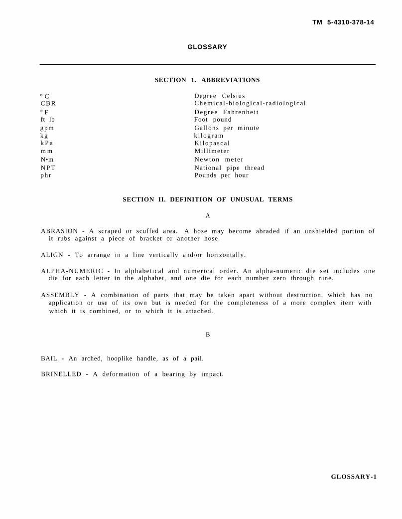
TM 5-4310-378-14
GLOSSARY
SECTION 1. ABBREVIATIONS
° C Degree CelsiusC B R Chemica l -b io log ica l - r ad io log ica l° F Degree Fah renhe i tft lb Foot poundg p m Gallons per minutek g k i l og ramk P a Ki lopasca lm m Mil l imete rN•m Newton me te rN P T National pipe threadp h r Pounds per hour
SECTION II. DEFINITION OF UNUSUAL TERMS
A
ABRASION - A scraped or scuffed area. A hose may become abraded if an unshielded portion ofit rubs against a piece of bracket or another hose.
ALIGN - To arrange in a line vertically and/or horizontally.
ALPHA-NUMERIC - In alphabet ical and numerical order . An alpha-numeric die set includes onedie for each letter in the alphabet, and one die for each number zero through nine.
ASSEMBLY - A combination of parts that may be taken apart without destruction, which has noapplication or use of its own but is needed for the completeness of a more complex item withwhich it is combined, or to which it is attached.
B
BAIL - An arched, hooplike handle, as of a pail.
BRINELLED - A deformation of a bearing by impact.
GLOSSARY-1

TM 5-4310-378-14
C
CARBON MONOXIDE -A poisonous gas that is made whiles fuel is burning, especially if thereis not quite enough air. The gas is colorless, odorless, and tasteless, but it can cause illnessdeath. See warning on the Warning page at front of manual.
CONDENSATION - A liquid formed from a vapor. Moisture carried in warm air will condensewhen it reaches a cold area, such as the surface of a fuel tank in sub-zero weather.
o r
CONTAMINATED - Made impure by contact or mixture. Exhaust fumes contain a poisonous gaswhich will contaminate the air in the nearby area.
CORROSION - A gradual wearing away caused by chemical action. Metals exposed to saltwater are likely to corrode.
D
DETERIORATE - A worsening of condition usually as a result or age or hostile environment, asopposed to mechanical damage.
DIAPHRAGM - An elastic material used as a boundary to sealdiaphragm allows the volume of the pump bowl to be variedac t ion .
and separate two areas. A pumpthus producing the pumping
DRAW BAR - A single piece handle used for lifting heavy objects.
DRY ROT - Rotting due to lack or air circulating around area.
E
EXPENDABLE - An item that is not repairable and is discarded if damaged.
EXPOSURE - Being in the presence of something, or in contact with something. Skin is exposed
to cleaning solvent when the solvent
FILTER - A device which removes dirt
contacts the skin during cleaning operations.
F
from air or a fluid.
FLASH POINT - The lowest temperature at which the vapors of a solvent will ignite and burn.
FLAPPER - A restriction in a line which limits the flow of fluid, or gases, to a singledirection. Flappers used in conjunction with a diaphragm pump and power source enable thepump to push/pull fluid in desired direction.
G
GALLING - A condition in which transfer of metal occurs between two parts made of likematerial (usual ly s teel) , usual ly occurr ing when mated parts have l imited relat ive motionunder high loads.
GLOSSARY-2

TM 5-4310-378-14
GLOSSARY
SECTION I. ABBREVIATIONS
°CCBR°Fft lbgpmkgkPammNomNPTphr
Degree CelsiusChemical-biological-radiologicalDegree FahrenheitFoot poundGallon per minutekilogramKilopascalMillimeterNewton meterNational pipe threadPounds per hour
SECTION II. DEFINITION OF UNUSUAL TERMS
A
ABRASION - A scraped or scuffed area. A hose may become abraded if an unshielded portion ofit rubs against a piece of bracket or another hose.
ALIGN - To arrange in a line vertically and/or horizontally.
ALPHA-NUMERIC - In alphabetical and numerical order. An alpha-numeric die set includes onedie for each letter in the alphabet, and one die for each number zero through nine.
ASSEMBLY - A combination of parts that may be taken apart without destruction, which has noapplication or use of its own but is needed for the completeness of a more complex item withwhich it is combined, or to which it is attached.
B
BAIL - An arched, hooplike handle, as of a pail.
BRINELLED - A deformation of a bearing by impact.
GLOSS ARY-1

TM 5-4310-378-14
c
CARBON MONOXIDE -A poisonous gas that is made while a fuel is burning, especially if thereis not quite enough air. The gas is colorless, odorless, and tasteless, but it can cause illness ordeath. See warning on the Warning page at front of manual.
CONDENSATION - A liquid formed from a vapor. Moisture carried in warm air will condensewhen it reaches a cold area, such as the surface of a fuel tank in sub-zero weather.
CONTAMINATED - Made impure by contact or mixture. Exhaust fumes contain a poisonous gaswhich will contaminate the air in the nearby area.
CORROSION - A gradual wearing away caused by chemical action. Metals exposed to saltwater are likely to corrode.
D
DETERIORATE - A worsening of condition usually as a result or age or hostile environment, asopposed to mechanical damage.
DIAPHRAGM - An elastic material used as a boundary to seal and separate two areas. A pumpdiaphragm allows the volume of the pump bowl to be varied thus producing the pumpingaction.
DRAW BAR - A single piece handle used for lifting heavy objects.
DRY ROT - Rotting due to lack or air circulating around area.
E
EXPENDABLE - An item that is not repairable and is discarded if damaged.
EXPOSURE - Being in the presence of something, or in contact with something. Skin is exposedto cleaning solvent when the solvent contacts the skin during cleaning operations.
F
FILTER - A device which removes dirt from air or a fluid.
FLASH POINT - The lowest temperature at which the vapors of a solvent will ignite and burn.
FLAPPER - A restriction in a line which limits the flow of fluid, or gases, to a singledirection. Flappers used in conjunction with a diaphragm pump and power source enable thepump to push/pull fluid in desired direction.
G
GALLING - A condition in which transfer of metal occurs between two parts made of likematerial (usuallyunder high loads.
GLOSSARY-2
steel), usually occurring when mated parts have limited relative motion

TMS-431O-378-14
-- 1
IMMERSE - To completely cover by fluid.
INHALATION - The act or breathing in..-. The breathing in or inhalation of carbon monoxide cancause illness or death. Refer to the Warning page at front of manual.
INITIAL - The first or starting condition.
INNER RACE - A component of a bearing assembly upon which the needles or rollers ride; usedto insure full contact and uniform surface condition.
K
KEYWAY - A channeI machined in a shaft into which a length or hardened steel stock, usually
-.
--
rectangular in cross section, is inserted to
LUBRICANT - Awhen used as a
material such as grease, orcoating on moving parts.
prevent the r~lative motion of a mating part.
LA
machine oil, that reduces friction, and preserves,
M
MALFUNCTION - Occurs when a unit fails to operate normally.
MATERIEL - Equipment, apparatus, and supplies of an organization such as an army.
o
OBSTRUCTION - An obstacle.
OPERATIONAL - Available for use in accordance with the applicable specification.
OUTPUT - The energy, power, or work produced by a system.
P
PIVOT - A short rod or shaft about which a related part rotates; the act of turning on or as if ona pivot.
PORT - A threaded hole through which fluid may pass, or pressure may be measured. Ports onthe pump are used to connect hoses, and to measure pressure.
PRIME - The act of introducing a liquid into a pump to increase the pump’s ability to overcomenegative head pressure.
PROTRUDING - Pushing or jutting outward; projecting.
PROVISIONS - Stipulations or qualifications. Also that which is provided; stock of necessarysupplies.
GLOSSARY-3

TM 5-4310-378-14
R
RADIOLOGICAL- Using ionizing radiation, or radioactive waves or particles. Radiologicalprotection shields the person or object from damage or injury due to harmful radiation.
RANGE - The minimum and maximum performance levels or any unit and including allmeasurable points between them.
RECIPROCATING - Equipment that acts along a straight line in alternating direction, i.e., theup and down motion of the connecting rod.
RESTRICTED - Limited, confined; prevented from moving. Also the reduction of cross-sectional area through which a gas or liquid must flow.
s
SCOPE - The extent of a activity or concept; the amount or information covered as in a book.
SHOCK - An extreme stimulation of the nerves and muscles caused by the passage of electriccurrent through the body. Also damage caused to mechanical equipment as result of suddenstoppage of motion.
SLINGING - Using a looped or hanging strap to raise and lower a heavy object, or for carrying orsupporting something.
STREET ELBOW - A 90-degree pipe elbow which has male threads on one end and femalethreads on the other.
STUD - A type of fastener, or alignment device, which has one end attached to a surface andthe other end protruding from that surface. The protruding portion of the stud may be usedas an alignment aid or, if threaded, as a fastener.
T
TIEDOWN - Strap or fastening device used to hold an object in position.
TORQUE - Force around an axis. It produces a rotary or twisting motion, and is measured byfoot pounds (ft lb) or newton-meters (N”m).
v
VALVE - A device used to control the flow of a fluid.
VAPOR - The gaseous form of any substance which is usually a liquid; vapors are present in theair around the substance.
WARPAGE - The twisting, bending, or other distortion of an object which alters its shape.
GLOSSARY-4

TM 5-4310-378-14
.
Subject, Para
A
Adjustments, Initial, 2-6Administrative Storage, 3-48Aftercooler Assembly, 3-37Air Cleaner Element, 3-29Air Cleaner, Compressor, 3-17Air Cleaner, Engine, 3-28Air Compressor, 1-14Air Compressor Overhaul, 5-2Air Compressor Unit Function, 1-13Air Compressor Unit, Purpose of, 1-7Air Discharge Hose, 3-43Air Tank, 4-9Air Tank, 3-42Altitudes, Operation in High, 2-15Areas, Operation in Sandy or Dusty, 2-16Assembly and Preparation for Use, 2-5
B
ALPHABETICAL INDEX
Subject, Para
Bearing Lubrication Procedure, Wheel, 3-4Bearings, Oil Seals, and Crankcase, Compressor
Crankshaft, 4-6Belt Guard Assembly, 3-11Belts, Matched Set V-, 3-12
~ Belt, Idler Assembly, 3-47
c
Cap and sight Glass, Oil Filler, 3-18Capabilities and Features, 1-8Carburetor, 3-30Cleaner Element, Air, 3-29Cleaner, Compressor Air, 3-17Cleaner, Engine Air, 3-28Coil, Engine Ignition, 3-25Cold, Operation in Extreme, 2-13Common Tools and Equipment, 3-5Compressor Air Cleaner, 3-17Compressor Assembly, 3-14Compressor Assembly, 4-3,- .Compressor Crankshaft, Bearings, Oil Seals, and
Crankcase, 4-6Compressor Cylinder Heads and Valves, 4-4Compressor Flywheel, 1-19Compressor Lubrication Procedure, 3-2. .Compressor Overhaul, Air, 5-2Compressor Crankshaft Bearingsj Oil Seals, and
Crankcase, 4-6
Compressor Pistons, Connecting Rods, andCylinders, 4-5
Compressor, Air, 1-14Connecting Rods, and Cylinders, Comrpessor
Pistons, 4-5Control Assembly, Engine Governor and, 4-8Control Assembly, Governor, 3-33Covers, and Deflectors, Ducts, 3-23Crankcase, Compressor Crankshaft, Bearings, Oil
Seals, and, 4-6Crankshaft, Bearings, Oil Seals, and Crankcase
Compressor, 4-6Cylinder Head and Gasket, 3-35Cylinder Heads and Valves, Compressor, 4-4Cylinders, Compressor Pistons, Connecting Rods,
and, 4-5
D
Deflectors, Ducts, Covers, and, 3-23Destruction of Army Materiel to Prevent Enemy
Use, 1-3Dipstick and Gasket, Oil, 3-36Discharge Hose, Air, 3-43Drain Valve, 3-39Drive Pulley, 3-31Ducts, Covers, and Deflectors, 3-23Dusty Areas, Operation in Sandy or, 2-16
E
Element, Air Cleaner, 3-29Engine Air Cleaner, 3-28Engine Assembly, 3-21Engine Assembly, 4-7Engine Governor and Control Assembly, 4-8Engine Ignition Coil, 3-25Engine Lubrication Procedure, 3-3Equipment Data, 1-11Equipment Improvement Recommendations (EIR),
Reporting, 1-5Equipment, Common Tools and, 3-5Equipment, Specital Tools, TMDE, and
Support. 3-6External Components, Location and Description
of, 1-9Extreme Cold, Operation in, 2-13Extreme Heat, Operation in, 2-14
Change 3 INDEX 1

TM 5-4310-378-14
Subject, Para
F
Features, Capabilities and, 1-8Filler Cap and Sight Glass, Oil, 3-18Filter Assemblies, Fuel Tank and Fuel, 3-22Flywheel, 3-24Flywheel, Compressor, 3-19Fuel Filter Assemblies, Fuel Tank and, 3-22Fuel Tank and Fuel Filter Assemblies, 3-22
G
Gage, Inflator, 3-44Gage, Pressure, 3-40Gasket, Cylinder Head and, 3-35Gasket, Oil Dipstick and, 3-36Glass, Oil Filler Cap and Sight, 3-18Governor, 4-8Governor Control Assembly, 3-33,4-8Governor Rod .Assembly, 3-32C.~v:rnor and Control Assembly, Engine, 4-8Guard Assembly, Belt, 3-11
H
Heads and Valves, Compressor Cylinder, 4-4Heat, Operation in Extreme, 2-14High Altitudes, Operation in, 2-15Hose, Air Discharge, 3-43Humid Conditions, Operation Under Rainy or, 2-17
I
Identiticaiton, 1-10Ignition Coil, Engine, 3-25Ignition Switch, 3-26Inflator Gage, 3-44Initial Adjustments, 2-6Interstage Relieve Valve, 3-16Idler Assembly, Belt, 3-47
L
Location and Description of External Component,1-9
Lubrication Methods, 3-1Lubrication Procedure, Compressor, 3-2Lubrication Procedure, Engine, 3-3
Subject, Para
Lubricaiton Procedure, Wheel Bearing, 3-4
M
Maintenance Forms, Records, and Reports, 1-2Matched Set V-Belts, 3-12Movement to a New Worksite, 2-12Movement, Preparation for, 2-11
N
New Worksite, Movement to a, 2-12
0
Oil Dipstick and Gasket, 3-36Oil Filler Cap and Sight Glass, 3-18Oil Seals, and Crankcase, Compressor Crankshaft,
4-6Operating Procedure, 2-7Operation, 2-9Operation Under Rainy or Humid Conditions, 2-17Operation at High Altitudes, 2-15Operation in Extreme Cold, 2-13Operation in Extreme Heat, 2-14Operation in Salt Water Areas, 2-18Operation in Sandy or Dusty Areas, 2-16Overhaul, Air Compressor, 5-2
P
Packing and Shipping, 3-49Parts, Repair, 3-7Pilot Valve, Safety, 3-38Pistons, Connecting Rods, and Cylinders,
Compressor, 4-5Plug, Spark, 3-27Preparation for Movement, 2-11Preparation for Storage and Shipment, 1-4Preparation for Use, Assembly and, 2-5Preventive Maintenance Checks and Services
(PMCS), Operator, 2-2Preventive Maintenance Checks and Services
(PMCS), Unit, 3-8Pressure Gage, 3-40Prevent Enemy Use, Destruction of Army Materiel
to, 1-3
INDEX 2 Change 3 * U.S. GOVERNMENT PRINTING OFFICE: 1991 554-1 23/20206

,— Subject, Para
TM 5-4310-378-14
Subject, Para
Procedure, Compressor Lubrication, 3-2Procedure, Engine Lubrication, 3-3Procedure, Wheel Bearing Lubrication, 3-4Pulley, Drive, 3-13Purpose of Air Compressor Unit, 1-7
R
I Rainy or Humid Conditions, Operation Under, 2-17“Recoil Starter Assembly, 3-34Records and Reports, Maintenance Forms, 1-2Relief Valve, Interstage, 3-16Relief Valve, Tank, 3-41Repair Parts, 3-7Reporting Equipment Improvement Recommenda-
tions (EIR), 1-5Rod Assembly, Governor, 3-32
s
Safety Pilot Valve, 3-38
ISalt Water Areas, Operation in, 2-18Sandy or Dusty Areas, Operation in, 2-16
.— Scope, 1-1Section Overview, 1-12Shipping, Packing and, 3-49Sight Glass, Oil Filler Cap and, 3-18Spark Plug, 3-27Special Tools, TMDE, and Support Equipment, 3-6Starter Assembly, Recoil, 3-34
I
Starting, 2-8Stopping, 2-10Storage and Shipment, Preparation for, 1-4Storage, Administrative, 3-48Support Equipment, Special Tools, TMDE, and,
3-6Switch, Ignition, 3-26
T
TMDE, and Support Equipment, Special Tools, 3-6Tank Relief Valve, 3-41Tank and Fuel Filter Assemblies, Fuel, 3-22Tank, Air, 3-42Tank, Air, 4-9Tires and Tubes, 3-46Tools and Equipment, Common, 3-5Tools, TMDE, and Support Equipment, Special,
3-6‘IYoubleshooting, 5-1Tube Assemblies, 3-15Tubes, Tires and, 3-46
u
Unit Function, Air Compressor, 1-13Unloader Valve Assemblies, 3-20Use, Assembly and Preparation for, 2-5
v
V-Belts, Matched Set, 3-12Valve Assemblies, Unloader, 3-20Valve, Drain, 3-39Valve, Interstage Relief, 3-16Valve, Safety Pilot, 3-38Valve, Tank Relief, 3-41Valves, Compressor Cylinder Heads and, 4-4
w
Warranty Information, 1-6Wheel Bearing Lubrication Procedure, 3-4Wheels, 3-45Worksite, Movement to a New, 2-12
—.
Change 1 INDEX-3/( INDEX-4 blank)

TM 5-4310-378-14
ByOrderoftheSecretary oftheArmy:—.
.Official:
R. L. DILWORTHBrigadier General, United States Army
The Adjutant General
JOHN A. WICKHAM, JR.Geneml, United States Armg
Chief of Stat7
DISTRIBUTION:To be distributed in accordance with DA Form 12-25A, Operator, Orgailizational, Direct
Support and General Support Maintenance requirements for Compressor, Reciprocating, Air,Gas, Hand Truck Mounted, 5 CF1.4, 175 PSI (20-902/3),
‘U.S. Government Printing OtfiW. 1991 — 281-504J47412


I
,-.
I
IIII
IIIII
III
m- RECOMMENDED CHANGES TO EQUIPMENT TECHNICAL PUBLICATIONS
PuBLICATION DATE P U B L I C A T I O N TITLE cOMpREs ‘OR ‘NIT ~RECIPROCATING,5CPM 175 PSI GASOLIN
TM 5-4310-378-14BE EXACT PIN-POINTWHERE ITIS
WBLICATIONNUM6ER
PARA-GRm
a-&
FIGvREN o
&a
b’
FROM (PRINT YOUR UNIT’SCOMPLETE ADCMESS)
PFc ro#4/ 00s .
OATE SENT
I 1 JULY 1986 IENGINE DRIVEN, HAND TRUCK MOUNTEDIN THIS SPACE TELL WHAT IS WRONGANO WHAT SHOULD BE DONE ABOUT IT
J-b 4$ p+a-ib +
~ Ak4’a4tk A&Au
~
y l~~e~g’q
w*
4- 3,/&!zd 14 AJ@f-CL &_, ” y??ti ~Wti**”
&--”J
UNTEO NAME CRAOE M TITLE ANO TELEPHO SIGN HERE‘ ae
2MJ Jhs, P:i (543)7 $$’///DA, R% 20202 PREVIOUS EDITIONS P S --IF YOUR OUTFIT WANTS TO KNOW ABOUT YOURARE OBSOLETE
RECOMMENDATION MAKE A CARBON COPY OF THISDRSTS.M Ovarprint 1, 1 Nov 80 ANO GIVE IT TO YOUR HEADQUARTERS
QFILL IN YOURUNITS ADDRESS
- - - - - - - - - - _ _ _ _ _ _ _ _
DEPARTMENT OF THE ARMY
OFFICIAL BUSINESS
REVERSE OF
FOLD BACK- - — — — - -
DA FORM 2028-2
-— --- __
Reverse of DRSTS-M Overprint z I
1 Nov 80 IIIIII
/II
‘/
IIIIIII
a
%
@o
8w
- - - - - - - - - - ——— mg0
$$a
COMMANDERU.S. ARMYA~TION AND TROOP COMMANDAm: AMSAT-I-MTS4300 GOODFELLOW BOULEVARDST. LOUIS, MO 63120-1798
I
/IIIIIIIIIII
/IIIIIIIiI

.II
● II
dI
I
., II
r II
I
REcOMMENDED cmNGES TO EQUIPMENT TECHNICAL PUBLICATIONS.
0
@~’’@ w’”u’w’TH”’s”BL’cA””’I PuMICATION OATE i PUBLICATI* TITLE COMPRESSOR U N I T ,WKICATION ~R
TM 5-4310-378-14BE EXACT PIHINT W
● AGEMO
#
&sl
MWTEO MANE. w
noMENo
on Tln
mTAUR
MO
Im T&g
—FROM. [PBINT VOUR UNITS COMRUE AOOWSS)
OATS SENT
,--lREcIPROcATING, 5CFM 175PsI ,GASOLINE
] 1 JULY 1986 lm~g ~CK MOUNTEDIN THIS SPACE TELL WMAT IS WRONOAm “NAT SHOULD ● E DON@ ASOUT ~
mNuw8n “ SION MERE.
DA ,-7s 2020-2 PREVIOUS EOITIONS P S.--IF YOUR OUTFIT WANTS TO KNOW ABOUV VOURARE 00SOLE7E. RECOMMENDATION WE A CARSON COPY OF THIS
DRSTSd Ovvcpdat ~ 1 Nov E& MO GIVE IT TO VOUR HEAOOUARTERS

REVERSE OF DAFORM 2028-2 Reverse of DRSTS-M overprint Z I
1 Nov SO IIIIIII ●II
:iI1IIiIII
F!k
QFILL IN YOUR oUNITS ADDRESS z0
FOLD BACK- - - - - - - - - - - - - - - - - - - - - - - - - - - - - - - - - - - - - - - - - - - - - 3
DEPARTMENT OF THE ARMYg
~o
OFFICIAL BUSINESS ur
zIIII
COMMANDER IU.S. ARMY AVIATION AND TROOP COMMAND IAm: AMSAT-I-MTS I
I4300 GOODFELLOW BOULEVARD IST. LOUIS, MO 63120-1798 1
I 4II
IIIiIIII oIII
●

.
b
9
II
IRECOMMENDED CHANGES TO EQUIPMENT TECHNICAL PUBLICATIONS
.
0@~’’@ ”’”’’TH”HspuBLBcATAoNoA’A! mSLICATION OATE I PUBLICATION TITLE COMPRESSOR UNIT, ‘
NoTASL8
MO
— —FROM. (PRINT YOUR UNITS COMPLETE AO~ESS)
4OATS SENT
_——RECIPROCATING, 5CPM 175 PSI , GASOLINE
D TRUCK MOUNTEDIN THIS 8PACR TELL WNAT W WRONOAmwNAT$NouLo BE DoNc AsouTITIT
I ● a
II
I123Q~T
8:~
es$eTs
IIII
I
III
IIII ‘ miNTEo LIUO rmwaus wussa SIGN MM
II, DA,-79 2028-2
● REVIOUS EDITIONS P S --IF YOUR OUTFIT WANTS TO KNOW ASOUT VOURAnE OSSOLETE. RECOMMENDATION MAKE A CARSON COPV OF TNIS
I DRSTSBM ovoqdat ~ 1 Dlov ~ ANO CMVE IT TO YOUR HEADQuARTERS.
REVERSE OF DA FORM 2028-2 Reverse of DRSTS-M Overprint ~ I
1 Nov 80 IIIIIIII
iII
:I
iIIIIIIII
i!
9
i?FILL IN YOUR oUNITS ADDRESS
8FOLD BACK v
- - - - - - - - - - - - - - - - - - - - - - - - - - - - - - - - - - - - - - - - - - - - - mDEPARTMEIsW OF THE ARMY c
o
5OFFICIAL BUSINESS u
r
z
COMMANDERU.S. ARMYA~ON AND TROOP COMMANDAlTN: AMSAT-I-MTS4300 GOODFELLOW BOULEV’ST. LOUIS, MO 63120-1798
.
PIN: 059977-004

I.-
. .
-.
II
RECOMMENDED CHANGES TO EQUIPMENT TECHNICAL PUBLICATIONS
oR~’’’wMw’’w’TspuBLucA’ON’ON’! PWLICATION OATE I ~B~IcATI~ TITLE COMPRESSOR UNIT, ‘PUWCATION NUMSER
TM 5.BE EXA
maw
MtNTEO
310-:P PIN-
t%k
Ms. ORA
B-14IINT WHERE IT IS
mowNo
on Tml
TA@LCNo
MD mm
——FROM: (PRINT YOUR UNIT’S COMPLETE ADDRESS)
OATE SENT
I RECIPROCATING, 5CFM 175 PSI ,GASOLINE1 JULY 1986 ENGINE DRIVEN , HAND TRUCK MOUNTED
IN THIS SPACE TELL “MAT IS WRONOANOWNAT SNOULDDEOOM8~ IT:
DA ,-7.2028-2 ~REVIOUS EDITIONS P S -4P VOUR OUTFIT WANTS TO KNOW ASOUT YOURA*E OSSOLETE. REOOMMENOATION MAKE A 0AR60N COPY OF TNIS
DRST&M Ov~nt ~ 1 -V SO. AND GIVE IT TO YOUR HEAOOUARTERS

REVERSE OF DA FORM 2028-2 Reverse of DRSTS-M Overprint ~ I
1 Nov 80 IIIIIIIIIIII
iI
iIIIIIIII
i!
COMMANDERU.S. ARMY A~TION AND TROOP COMMANDXITN: AMSAT-I-MTS4300 GOODFELLOW BOULEVARDST. LOUIS, MO 63120-1798
QP
FILL IN YOUR oUNITS ADDRESS
3FOLD BACK w
- - - - - - - - - - _ _ _ _ _ _ _ _ _ _ _ _ _ _ _ _ _ _ _ _ ,. _ _ _ - , _ _ _ _ _ _ _ _ _ _ mDEPMTMENT OF THE ARMY E
oE$
OFFICIAL BUSINESS ur
zII
iIIIIIII
:II
!III
:IIII
PIN: 059977-004

The Metric System and Equivalents
Iirlear Meuurs Liqw”d Mauurs
1 centimeter = 10 millimeters = .39 inch1 decimeter = 10 centimeters = 3.94 inches1 meter = 10 decimeters = 39.37 inches1 dekameter = 10 meters = 32.8 feet1 hectometer = 10 dekameters = 328.08 feet1 kilometer = 10 hectometers = 3,280.8 feet
1 centigram = 10 milligrams = .15 grain1 decigram . 10 centigrams = 1.54 grains1 gram = 10 decigram = .035 ounce1 dekagram . 10 grams . .35 ounce1 hectogram = 10 dekagrams = 3.52 ounces1 kilogram = 10 hectograms = 2.2 pounds1 quintal = 100 kilograms = 220.46 pounds1 metric ton = 10 quintals = 1.1 short tons
inchesfeetyardsmilessquare inchessquare feetsquare yardssquare milesacrescubic feetcubic yardsfluid ouncespintsquartsgallonsouncespoundsshort tonspound-feetpound-inches
To
1 centiliter = 10 milliters = .34 fl. ounce1 deciliter = 10 centiliters = 3.38 fl. ounces1 liter = 10 deciliters = 33.81 fl. ounces1 dekaliter = 10 liters = 2.64 gallons1 hectoliter = 10 dekaliters = 26.42 gallons1 kiloliter = 10 hectolitere = 264.18 gallons
SquamMeasum
1 sq. centimeter = 100 sq. millimeters = .155 sq. inch1 sq. decimeter = 100 sq. centimeters = 15.5 sq. inches1 sq. meter (centare) = 100 sq. decimeters = 10.76 sq. feet1 sq. dekameter (are) = 100 sq. meters = 1,076.4 sq. feet1 sq. hectometer (hectare) = 100 sq. dekameters = 2.47 acres1 sq. kilometer = 100 sq. hectometers = .386 sq. mile
Cabic Meuum
1 cu. centimeter = 1000 cu. millimeter = .06 cu. inch1 cu. decimetir = 1000 cu. centimeters = 61.02 cu. inches1 cu. meter = 1000 cu. decimeters = 35.31 cu. feet
Approximate Conversion Factors
centimetersmetersmeterskilometerssquare centimeterssquare meterssquare meterssquare kilometerssquare hectometerscubic meterscubic metersmilliliterslitersliterslitersgramskilogramsmetric tonsnewton-metersnewton-meters
“F Fahrenheittemperature
bildtiply by
2.540.305.914
1.6096.451
.093
.8362,590
.405
.028
.76529,573
.473
.9463.785
28.349.454.907
1.356.11296
To CIUIW
ounce-inchescentimetersmetersmeterskilometerssquare centimeterssquare meterssquare meterssquare kilometerssquare hectometerscubic meterscubic metersmilliliterslitersliterslitersgramskilogramsmetric tons
Temperature (Exact)
5/9 (after Celsius “csubtracting 32 I temperature
To
newton-metersinchesfeetyardsmilessquare inchessquare feetsquare yardssquare milesacrescubic feetcubic yardsfluid ouncespintsquartsgallonsouncespoundsshort tons
hfldtipty by
.007062,394
3.2801.094
.621
.15510.764
1.196.386
2.47135.315
1.308.034
2.1131,057,264,035
2.2051,102

PIN : 059977-004

This fine document...
Was brought to you by me:
Liberated Manuals -- free army and government manuals
Why do I do it? I am tired of sleazy CD-ROM sellers, who take publicly available information, slap “watermarks” and other junk on it, and sell it. Those masters of search engine manipulation make sure that their sites that sell free information, come up first in search engines. They did not create it... They did not even scan it... Why should they get your money? Why are not letting you give those free manuals to your friends?
I am setting this document FREE. This document was made by the US Government and is NOT protected by Copyright. Feel free to share, republish, sell and so on.
I am not asking you for donations, fees or handouts. If you can, please provide a link to liberatedmanuals.com, so that free manuals come up first in search engines:
<A HREF=http://www.liberatedmanuals.com/>Free Military and Government Manuals</A>
– SincerelyIgor Chudovhttp://igor.chudov.com/
– Chicago Machinery Movers