Embed Size (px)
Citation preview

1FLENDER LOHER
Technical List Variable–Speed Drive Systems UN 04 en
Table of contents 1. . . . . . . . . . . . . . . . . . . . . . . . . . . . . . . . . . . . . . . . . . . . . . . . . . . . . . . .
1 Basic concepts 3. . . . . . . . . . . . . . . . . . . . . . . . . . . . . . . . . . . . . . . . . . . . . . . . . . . . . . . . . .
1.1 Quality assurance 3. . . . . . . . . . . . . . . . . . . . . . . . . . . . . . . . . . . . . . . . . . . . . . . . . . . . . . . .
1.2 Standards and specifications 3. . . . . . . . . . . . . . . . . . . . . . . . . . . . . . . . . . . . . . . . . . . . . . .
1.3 General 4. . . . . . . . . . . . . . . . . . . . . . . . . . . . . . . . . . . . . . . . . . . . . . . . . . . . . . . . . . . . . . . . .
1.4 Frequency inverters 4. . . . . . . . . . . . . . . . . . . . . . . . . . . . . . . . . . . . . . . . . . . . . . . . . . . . . . .
1.5 Three–phase motors for inverter operation and mains operation 6. . . . . . . . . . . . . . . . .
1.6 Scope of assignment tables 6. . . . . . . . . . . . . . . . . . . . . . . . . . . . . . . . . . . . . . . . . . . . . . . .
1.7 Motor rating 6. . . . . . . . . . . . . . . . . . . . . . . . . . . . . . . . . . . . . . . . . . . . . . . . . . . . . . . . . . . . . .
2 Inverter–operated three–phase motors 7. . . . . . . . . . . . . . . . . . . . . . . . . . . . . . . . . . . . 2.1 Limit curve of the torque 7. . . . . . . . . . . . . . . . . . . . . . . . . . . . . . . . . . . . . . . . . . . . . . . . . . .
2.2 Drives with quadratic load torque 7. . . . . . . . . . . . . . . . . . . . . . . . . . . . . . . . . . . . . . . . . . .
2.3 Drives with constant load torque 7. . . . . . . . . . . . . . . . . . . . . . . . . . . . . . . . . . . . . . . . . . . .
2.3.1 Motors with self–ventilation 8. . . . . . . . . . . . . . . . . . . . . . . . . . . . . . . . . . . . . . . . . . . . . . . .
2.3.2 Motors with forced ventilation 8. . . . . . . . . . . . . . . . . . . . . . . . . . . . . . . . . . . . . . . . . . . . . . .
2.4 Motors with higher frequency range 9. . . . . . . . . . . . . . . . . . . . . . . . . . . . . . . . . . . . . . . . .
2.4.1 Operation with field weakening 9. . . . . . . . . . . . . . . . . . . . . . . . . . . . . . . . . . . . . . . . . . . . .
2.4.2 Operation at constant flux up to f � 3� fN 9. . . . . . . . . . . . . . . . . . . . . . . . . . . . . . . . . . . . .
2.4.2.1 Drives with quadratic load torque 10. . . . . . . . . . . . . . . . . . . . . . . . . . . . . . . . . . . . . .
2.4.2.2 Drives with constant load torque 10. . . . . . . . . . . . . . . . . . . . . . . . . . . . . . . . . . . . . . . . . . . .
3 Assignment tables 11. . . . . . . . . . . . . . . . . . . . . . . . . . . . . . . . . . . . . . . . . . . . . . . . . . . . . . . 3.1 Tolerances 11. . . . . . . . . . . . . . . . . . . . . . . . . . . . . . . . . . . . . . . . . . . . . . . . . . . . . . . . . . . . . . .
3.2 Three–phase motors for low voltage with squirrel cage, Totally enclosed fan–cooled Class F insulation – Utilization B, operated at PWM–Inverter 12. . . . . . . . . . . . . . . . . . .
3.3 Three–phase motors for low voltage with squirrel cage, Totally enclosed fan–cooled, Class F insulation – Utilization F, operated at PWM–Inverter 28. . . . . . . . . . . . . . . . . . . .
3.4 Explosion–proof three–phase motors for low voltage with squirrel cage,Protection type ”Flameproof Enclosure” acc. to EN 50 018Class F insulation – Utilization B, operated at PWM–Inverter 44. . . . . . . . . . . . . . . . . . .
3.5 Explosion–proof three–phase motors for low voltage with squirrel cage,Protection type ”Flameproof Enclosure” acc. to EN 50 018Class F insulation – Utilization F, operated at PWM–Inverter 60. . . . . . . . . . . . . . . . . . . .
3.6 Six–phase motors for low voltage with squirrel cage, Totally enclosed fan–cooledClass F insulation – Utilization B, operated at I–Inverter 76. . . . . . . . . . . . . . . . . . . . . . .
4 Information to assignment tables 88. . . . . . . . . . . . . . . . . . . . . . . . . . . . . . . . . . . . . . . . . 4.1 Motor data for other rated voltages 88. . . . . . . . . . . . . . . . . . . . . . . . . . . . . . . . . . . . . . . . . .
4.2 Motor data for a different rated frequency 88. . . . . . . . . . . . . . . . . . . . . . . . . . . . . . . . . . . .
4.2.1 Power increase of the 60 Hz–motor compared to the 50 Hz–motor 88. . . . . . . . . . . . . .
4.2.2 Motor data of the 60 Hz–motor 88. . . . . . . . . . . . . . . . . . . . . . . . . . . . . . . . . . . . . . . . . . . . .
4.3 Motor data for inverter operation 88. . . . . . . . . . . . . . . . . . . . . . . . . . . . . . . . . . . . . . . . . . . .
4.3.1 Conversion of the motor current 88. . . . . . . . . . . . . . . . . . . . . . . . . . . . . . . . . . . . . . . . . . . .
4.3.2 Conversion of the motor power factor 89. . . . . . . . . . . . . . . . . . . . . . . . . . . . . . . . . . . . . . . .
4.3.3 Motor efficiency for inverter operation 89. . . . . . . . . . . . . . . . . . . . . . . . . . . . . . . . . . . . . . . .
4.3.3.1 Efficiency on the PWM–Inverter 89. . . . . . . . . . . . . . . . . . . . . . . . . . . . . . . . . . . . . . . . . . . .
4.3.3.2 Efficiency on the I–Inverter 89. . . . . . . . . . . . . . . . . . . . . . . . . . . . . . . . . . . . . . . . . . . . . . . . .
4.3.4 System efficiency 89. . . . . . . . . . . . . . . . . . . . . . . . . . . . . . . . . . . . . . . . . . . . . . . . . . . . . . . . .
4.4 Six–phase motors and three–phase motors for 12/24–pulse inverters 90. . . . . . . . . . . .

2 FLENDER LOHER
5 Considerations for rating and design 91. . . . . . . . . . . . . . . . . . . . . . . . . . . . . . . . . . . . . 5.1 Admissible voltage stress 91. . . . . . . . . . . . . . . . . . . . . . . . . . . . . . . . . . . . . . . . . . . . . . . . . .
5.1.1 Voltage stress by PWM–Inverter 91. . . . . . . . . . . . . . . . . . . . . . . . . . . . . . . . . . . . . . . . . . . .
5.1.1.1 Inverter–operated motor with sine filter 91. . . . . . . . . . . . . . . . . . . . . . . . . . . . . . . . . . . . . .
5.1.2 Voltage stress by I–Inverter 92. . . . . . . . . . . . . . . . . . . . . . . . . . . . . . . . . . . . . . . . . . . . . . . .
5.2 Noise 92. . . . . . . . . . . . . . . . . . . . . . . . . . . . . . . . . . . . . . . . . . . . . . . . . . . . . . . . . . . . . . . . . . .
5.3 Overload capability 93. . . . . . . . . . . . . . . . . . . . . . . . . . . . . . . . . . . . . . . . . . . . . . . . . . . . . . .
5.3.1 Overload capability of the cold motor 93. . . . . . . . . . . . . . . . . . . . . . . . . . . . . . . . . . . . . . . .
5.3.2 Overloading of the motor at operating temperature 94. . . . . . . . . . . . . . . . . . . . . . . . . . . .
5.3.2.1 Overload capability at constant cooling 94. . . . . . . . . . . . . . . . . . . . . . . . . . . . . . . . . . . . . .
5.3.2.2 Overload capability of self–ventilated motors at constant load torque 95. . . . . . . . . . . . .
5.4 Inverter operation of explosion–proof motors 96. . . . . . . . . . . . . . . . . . . . . . . . . . . . . . . . .
5.4.1 Motors in ignition protection EEx d: ”Flameproof Enclosure” acc. to EN 50018 96. . . .
5.4.2 Motors in ignition protection EEx e: ”Increased Safety” acc. to EN 50019 96. . . . . . . . .
5.4.3 Motors in ignition protection EEx n: ”Non–sparking” or ”Non–sparking electrical equipment” acc. to EN 50021 96. . . . . . . .
5.4.4 Terminal boxes 96. . . . . . . . . . . . . . . . . . . . . . . . . . . . . . . . . . . . . . . . . . . . . . . . . . . . . . . . . . .
5.5 Shaft voltages and bearing currents 96. . . . . . . . . . . . . . . . . . . . . . . . . . . . . . . . . . . . . . . . .
5.6 Mechanical limit speeds 97. . . . . . . . . . . . . . . . . . . . . . . . . . . . . . . . . . . . . . . . . . . . . . . . . . .
5.7 Relubrication intervals, grease life, grease quantities 98. . . . . . . . . . . . . . . . . . . . . . . . . .
5.8 Motor protection 99. . . . . . . . . . . . . . . . . . . . . . . . . . . . . . . . . . . . . . . . . . . . . . . . . . . . . . . . . .
5.9 Electromagnetic compatibility (EMC) 99. . . . . . . . . . . . . . . . . . . . . . . . . . . . . . . . . . . . . . . .
5.9.1 EMC–Directive 99. . . . . . . . . . . . . . . . . . . . . . . . . . . . . . . . . . . . . . . . . . . . . . . . . . . . . . . . . . .
5.9.1.1 Mains–operated asynchronous machines 99. . . . . . . . . . . . . . . . . . . . . . . . . . . . . . . . . . . .
5.9.1.2 Inverter–operated asynchronous machines 99. . . . . . . . . . . . . . . . . . . . . . . . . . . . . . . . . . .
5.9.1.3 Additional equipment 99. . . . . . . . . . . . . . . . . . . . . . . . . . . . . . . . . . . . . . . . . . . . . . . . . . . . . .
6 Motors for high speeds 100. . . . . . . . . . . . . . . . . . . . . . . . . . . . . . . . . . . . . . . . . . . . . . . . . .

3FLENDER LOHER
1 Basic concepts
1.1 Quality assurance1.2 Standards and specifications
1.1 Quality assuranceFrom quotation to delivery, our complete order handling for electrical machines is done on the basis of an approved quality assurance system complying with the following quality standards:
DIN ISO 9001 / EN 29 001
Loher is certified in accordance with the Directive 94/9/EC:PTB 99 ATEX Q 003
1.2 Standards and specifications The motors comply with the relevant standards and specifications, especially with:
Type series Title DIN / EN IEC
Rotating electrical machines – DINRated data and operational behaviour
EN 60 034-1 IEC 60034-1IEC 60085
Determination of losses and of the efficiency DIN EN 60034-2 IEC 60034-2
IP-enclosures DIN EN 60034-5 IEC 60034-5
Cooling systems DIN EN 60034-6 IEC 60034-6
all types Mounting arrangements DIN EN 60034-7 IEC 60034-7all types
Terminal designations and direction of rotations DIN EN 60034-8 IEC 60034-8
Limit values for noises DIN EN 60034-9 IEC 60034-9
Acoustics: Procedure for measurement of airborne noise DIN emitted of rotating electrical machines
EN ISO 1680 –
Installed thermal protection – IEC 60034-11
Starting characteristics of motors with squirrel cage DIN up to and including 660V, 50 Hz
EN 60034-12 IEC 60034-12
Mechanical vibrations DIN EN 60034-14 IEC 60034-14
IEC–standard voltages DIN EN 60038 IEC 60038
Three–phase motors for general use DIN with standardized dimensions and outputs
EN 50347 IEC 60072 1
Output assignment for Increased Safety ”e” DIN 42677-2
Centerholes with threads DIN 332 –
Keys, slots, high shape DIN 6885-1 –
Mounting of electrical equipment DINin hazardous areas
EN 60079–14 IEC 60079–14
Motors for
Electrical apparatus for hazardous areas DINgeneral regulations
EN 50014 –
Motors forhazardousareas
Non–sparking ”n” DIN EN 50021 –hazardousareas
Increased Safety ”e” DIN EN 50019 –
Flameproof Enclosure ”d” DIN EN 50018 –
Electrical apparatus for the application in areas DINwith combustible dust
EN 50281–1–1 –
1 Only dimensions are determined in IEC 60072; an output assignment is not yet available.

4 FLENDER LOHER
1.3 General1.4 Frequency inverters
1.3 General
Three–phase motors with squirrel cageare suitable for mains operation at con-stant voltage and frequency as well asfor frequency inverter operation at va-riable voltage and frequency. Depen-ding on the connection the operationalbehaviour of the motor is subject tochanges. Mains–operated motors areworking with sinusoidal voltages andcurrents at an almost constant speed.With frequency inverters betweenpower supply and motor an infinitely va-riable speed control is achieved. In thiscase, however, the motor voltages andmotor currents are no longer sinusoidal.
For the motor assignment the changedbehaviour in contrast to mains opera-tion have to be considered.
This catalogue serves to assign LoherMotors for an application with fre-quency inverters. The detailed assign-ment tables include suitable motors andits operation data for the most importantapplications. The essential features ofan inverter operation are also mentio-ned.
1.4 Frequency inverters
For speed control of three–phase mo-tors within the output range of this cata-logue, the following inverter types areused:
� voltage–source inverters (pulse–controlled inverters orPWM–Inverters)
� current–source inverters(I–Inverters)
Figure 1 shows a comparison of theboth inverter types as well as the typicalvoltages and currents occurring in themotor and power supply system.
The motor voltage– and motor currentbehaviour for a PWM–Inverter opera-tion depends on the pulse frequencyand on the manufacturer–specific pulsepattern. These characteristics have aninfluence on the operation and the sui-tability of a motor for the inverter opera-tion.
For connection of an I–Inverter the vol-tages and currents occurring in the mo-tor are not influenced by the invertermanufacturer.

5FLENDER LOHER
Frequency inverters, comparison
Inverter system PWM–Inverter I–Inverter
Mains voltage uL
Mains current iL
Mains converter
Intermediate circuit
Machine converter
Motor voltage u
Motor current i
Speed–torque range
typ. frequency range f = 0 ...100...500 Hz f = (0) ...5...50...(100) Hz1
typ. speed range n = 0 ...4 � nN n = (0) ...0.1...1...(2) �nN1
1 Values in parenthesis with additional measures
typ. power range 0 – 2000 kVA (low–voltage inverters)700–10000 kVA (medium–voltage inverters)
50 – 5000 kVA (low–voltage inverters)2000–10000 kVA (medium–voltage inverters)
typ. applications Fans, pumps, machine tools, conveyor belts, assembly lines, win-der drives, metering drives, air–conditioning drives, hoisting drives,mixers, extruders, wind power plants
High–power pumps and fans, mills, centrifuges, decanters, agitators, rolling mills, extruders, mixers, compressors
Essential features 2–quadrant operation(4–quadrant operation with additional expenditure)Mains current harmonics manufacturer–dependentMains–cos ϕ � 1High speed control range
4–quadrant operationLow mains current harmonicsMains–cos ϕ � 0.95Limited speed control range
Fig. 1: Comparison of PWM–Inverter and I–Inverter
non–controlled
bridge
Intermediate circuit
capacitor
self–commutated
converter
controlled
bridge
Intermediate circuit
choke
self–commutated
converter

6 FLENDER LOHER
1.5 Three–phase motors for inverter operation and mains operation1.6 Scope of assignment tables1.7 Motor rating
1.5 Three–phase motors for inverter operation and mainsoperation
Motors being suitable for both inverteroperation and mains operation are indi-cated in the assignment tables. Apartfrom some exceptions these motorscomply with the motors in the currentTechnical Lists. This is above all appli-cable to the type series
AN..Three–phase motors for low voltagewith squirrel cage, totally enclosed fan–cooled
DN.. Explosion–proof three–phase motorswith squirrel cage for low voltage, pro-tection type ”Flameproof Enclosure”
In an exceptional case the motors areoptimized for inverter operation, e.g. byspecial rotors. In the tables these mo-tors are especially marked.
The available catalogue also containsinformation on frequency inverter ope-ration of EEx e– and Ex n–motors.
1.6 Scope of assignment tables
The assignment tables were issued formotors operated at the inverters
LOHER DYNAVERT® T
(PWM–Inverter)
and for 6�motors at the inverters
LOHER DYNAVERT® I
(I–Inverter)
The admissible powers for 3 � motorsat the LOHER DYNAVERT® I (I–Inver-ter) are obtained from the tables foroperation at the PWM–Inverter less10%
The scope of the assignment tablesalso covers inverters of other manufac-turers with an equivalent pulse pattern.
A nearly equivalent pulse pattern isachievable with a regulation to sinusoi-dal motor current and the followingpulse frequencies:
P � 30 kW : fP � 4 kHz30 kW � P � 130 kW : fP � 3 kHz
P 130 kW : fP � 2 kHz
1.7 Motor rating
The motors of this catalogue are desi-gned in a way that for a rated operationaccording to EN 60034–1 or VDE 0530Part 1 they are in compliance with thetemperature limits of Insulation Class Bor in single cases Insulation Class F.
Rated operation means above all
� mains operation practically with si-nusoidal rated voltage and con-stant frequency of 50 Hz (motorsfor 60 Hz: see 4.2)
� continuous duty (Duty type: S1) ofthe motor with its rated power PN,corresponding with the rated torqueMN and the rated speed nN
� constant speed� coolant temperature: � 40 �C� altitude of installation �1000m
above sea level
Inverter operation differs from the ra-ted conditions:
� non–sinusoidal variable voltagesand currents
� variable frequency and variablespeed
� optional utilization of the motors toInsulation Class B or InsulationClass F
Table 1 indicates the special featureswhich have to be considered for inver-ter–operated motors (see DIN IEC/TS60034–17 or VDE 0530 Part 17 and ourTechnical Publication No. 4: Speedcontrol of asynchronous machines).
Table 1: Inverter operation effects
To be observed for inverter operation Explanationssee Chapter
Reduction of the admissible torque due toadditional losses of non–sinusoidal voltages and currents
2.14.3.3
Reduction of the admissible torque due to decreased cooling of self–ventilated motors at low speed
2.3.12.4.2.2
Reduction of the achievable torque with field weakening 2.4.1
Reduction of the admissible torque due to increased iron losses for operation at constant flux and frequencies exceeding the rated frequency (e.g. 87Hz)
2.4.2
Higher insulation stress 5.1
Higher noise due to self–ventilation at frequencies exceeding the rated frequency 5.2
Partially increased noise due to harmonicsor operation at a certain speed (e.g. frame oscillation exciting)
5.2
Compliance with rules for the use of explosion–proof motors 5.4
Occurrence of bearing currents and shaft voltages 5.5
Compliance with mechanical speed limits for operation at speeds exceeding the rated speed(bearing speeds, centrifugal forces, critical speed of rotor shaft,maximum speed of plastic fans for the use of motors in the hazardous area of Zone 2)
5.6
Shorter grease life and relubrication times at speeds exceeding the rated speed 5.7

7FLENDER LOHER
2 Inverter–operated three–phase motors
2.1 Limit curve of the torque2.2 Drives with quadratic load torque2.3 Drives with constant load torque
The torque–speed–behaviour of themotor and the working machine is im-portant for the designing of electricdrives. Whereas the torque–speed–characteristic is important for mains–fed asynchronous motors, an inverteroperation requires above all the consi-deration of the limit curve of the tor-que.
2.1 Limit curve of the torque
Figure 2 shows the typical behaviour ofthe motor torque for mains operationwith the characteristic features startingtorque, pull–up torque and breakdowntorque.
From the overall torque–speed–cha-racteristic line (M–n–characteristic)only the steep range marked by a bro-ken line is normally used for inverteroperation. With the frequency– and vol-tage control of the inverter operation aparallel displacement of this range to lo-wer speeds is possible by a frequencyreduction. Higher frequencies displacethis range at a constant flux parallel andat field weakening with decreasingsteepness to the right resulting in hig-her speeds. The continuously achieva-ble torque is drawn as limit curve in Fi-gure 2.
The limit curve indicates for constantflux the thermally admissible torque forcontinuous duty.
With the limit torque the motor in conti-nuous duty is not heating more thanspecified by its insulation class.
On principle an operation at speed”Zero” is also possible.(Limit torque upon request)In the field weakening range the limitcurve indicates up to limit frequency fL
the torque which is achievable at an ap-proximately constant motor current andthus constant inverter current. Beyondthe limit frequency the achievable tor-que is limited by the strongly decrea-sing breakdown torque.
The following principle has to be consi-dered for the designing of inverterdrives:
� The torque of the working machine(load torque) at continuous dutymust always be less than the limittorque of the motor.
Higher motor torques are generallypossible, but at continuous duty theycause a higher temperature rise and re-quire more current from the inverter (asto overload capability see chapter 5.3).
The motor power can be determinedfrom the M–n–curves. The power out-put of the motor is calculated at everypoint of the M–n–curve from the torqueand the relating speed.
P = 2πnM
or
It has to be distinguished between thepossible power at inverter operationand the rated power (applicable formains operation).In the M–n–curves and in the assign-ment tables the rated power PN (to becalculated from the rated torque MN andthe rated speed nN) is marked by apoint. The power at inverter operation(e.g. P1) is marked by a cross.
For inverter operation the maximumpossible torque is often less than the ra-ted torque. It results from the physicalconnections (laws of growth) that forlarger motors a higher reduction of thetorque is required than for smaller mo-tors. The extent of the torque reductionalso depends on the working machine(constant or quadratic load torque), thecooling type, the speed range and theutilization (Insulation Class B or F).
In case of smaller motors and for utiliza-tion to Insulation Class F the power atinverter operation can also be a littlehigher than the rated power.
2.2 Drives with quadratic load torque
The load torque of centrifugal pumpsand fans (ventilators) is increasing qua-dratically with the speed. Figure 3shows that a motor with self–ventilationis always suitable. The load torque is al-ways less than the motor torque.
2.3 Drives with constant load torque
For drives with constant load torque likee.g. stirrers or hoisting gears it has to bedistinguished whether the used motorwill be cooled with a self–ventilation onthe motor shaft or by forced ventilation.
Fig. 2: Torque–speed–characteristic of the asynchronous motorand limit torque for inverter operation
M–n–characteristic for mains operation
Rated pointLimit curve with forced ventilation Limit curve for constant flux
Limit curve with self–ventilation
Limit curve for field weakening
Displacement of this section of the characteristic curve by frequency control
PkW
� 19550
� nmin1 �
MNm

8 FLENDER LOHER
2.3.1 Motors with self–ventilation2.3.2 Motors with forced ventilation
2.3.1 Motors with self–ventilation
For self–ventilated motors the coolingeffect is reduced with the decreasingspeed. In order to avoid an overheatingof the motor in continuous duty at lowspeed, the motor torque and conse-quently the current and the heat–gene-rating losses have to be reduced.
As shown in Figure 4, the achievabletorque depends on the speed controlrange. For a control range of e.g. 1:10the motor can be operated at a constantload torque ML4. This load torque andthe rated speed nN (corresponding tothe rated frequency 50 Hz) are used tocalculate the reduced power P4 whitchis less than the rated power PN.
Note: The torque and motor power reductione.g. to ML4 or P4 is only required whenthe motor is operated at low speed con-tinuously or for a longer time. If the ope-ration at low speed only takes a shorttime (some minutes) a reduction is notnecessary (also see chapter 5.4).This is important e.g. for drives with anincreased breakaway torque. Since thestart normally is of a short duration, it isnot necessary to consider the increa-sed breakaway torque for thermal rea-sons. However, it should not be forgot-ten that higher torque (for the usual con-trol to constant stator flux) requires hig-her current from the inverter.
2.3.2 Motors with forced ventilation
The reduction of motor torque andpower at constant load torque and largecontrol range can be avoided by usingmotors with forced ventilation. The coo-ling effect is then independent from themotor speed (Figure 5).
There is a special feature for larger mo-tors as from Type ANSA–355LN (Va-rio). These motors have two fans, oneinside and one outside the frame. Theinternal fan cannot be driven separa-tely, hence the cooling effect is speed–dependent. Also when an external se-parately driven fan is used, the limittorque decreases at lower speed.
Fig. 3 Motors with self–ventilation for pump– and fan drive (ML � n2)
Fig 4: Torque reduction due to decreased cooling effect for motors withself–ventilation (ML = const.)
ML2 constant load torque in speed control range 1:3
ML3 constant load torque in speed control range 1:5
ML4 constant load torque in speed control range 1:10
Fig. 5: Torque at constant load torque for forced ventilation
ML5 constant load torque in speed control range 1:10
Rated power of the motor for mains operation
Limit curve for motors with self–ventilation
Standard power of the motor for inverter operation

9FLENDER LOHER
2.4 Motors with a higher frequency range2.4.1 Operation with field weakening2.4.2 Operation at constant flow up to
2.4 Motors with higher frequencyrange
Above its rated frequency the inverter–fed motors can be operated differently.All motors can be operated with fieldweakening (2.4.1), for certain motorsan operation at constant flux is alsopossible (2.4.2) (Figure 6).
2.4.1 Operation with field weakening
At this operation a frequency increasebeyond the rated frequency occurs withconstant voltage. This reduces the ma-gnetic flux and the available torque de-creases until the limit frequency fL withM�1/f. The power output of the motorremains constant.
In the field weakening range the break-down torque MB of the motor is stronglydecreasing (MB�1/f2). From the limitfrequency fL a stronger reduction of thetorque is required, as otherwise the ne-cessary distance between the break-down torque MB and the torque M beco-mes too small.
In practice the breakdown torqueshould be at least 40% over the statio-nary required torque. For dynamic pro-cesses (accelerating, braking) an di-stance of 20% is sufficient.
2.4.2 Operation at constant flux
up to f � 3� fN
This operation requires motors whichare designed for mains operation inY–connection. For inverter operationthe windings are connected in delta.Due to this an operation at constant flux
is possible up to the 3� –fold rated fre-quency. Hence, motors for a rated fre-quency of 50 Hz can also be operated
at constant speed with 3� � 50 Hz � 87Hz.However due to the iron losses PFe, in-creasing with the frequency, a torquereduction is required. In spite of this apower increase of up to 60% comparedto rated power is achievable with thismethod. With increasing frame sizesthis power increase becomes less.For larger frame sizes a motor of a spe-cial design different from the standardmotor is recommendable (upon re-quest).For motors with forced ventilation thecooling remains constant over thewhole speed range. At high speeds thecooling effect for motors with self–venti-lation improves insignificantly. The hig-her utilization achieved in this way is ofsuch an insignificance that in the as-signment tables no difference wasmade between motors with self– andforced cooling.
Attention:For self–ventilated motors the fan noisestrongly increases with the speed. The-refore is e.g. the sound pressure levelof a 2–pole motor at 87 Hz on the ave-rage by approx. 13 dB(A) higher than at50 Hz (see chapter 5.2). The mechani-cally or magnetically caused noises arealso increasing with the frequency butless than the fan noise .In case of forced ventilation the noiseincreases at 87 Hz by only approx.4 dB(A) on the average.
f � 3� fN
Fig. 6: Constant flux and field weakening range
Limit curve with forced ventilation
Limit curve with self–ventilation Limit curve for field weakening
constant flux Field weakening
10 FLENDER LOHER
2.4.2.1 Drives with quadratic load torque2.4.2.2 Drives with constant load torque
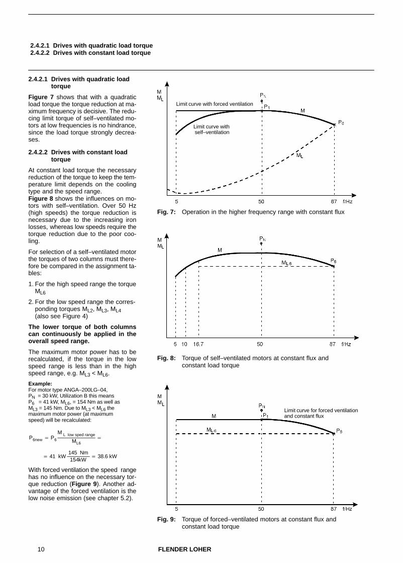
2.4.2.1 Drives with quadratic loadtorque
Figure 7 shows that with a quadraticload torque the torque reduction at ma-ximum frequency is decisive. The redu-cing limit torque of self–ventilated mo-tors at low frequencies is no hindrance,since the load torque strongly decrea-ses.
2.4.2.2 Drives with constant loadtorque
At constant load torque the necessaryreduction of the torque to keep the tem-perature limit depends on the coolingtype and the speed range. Figure 8 shows the influences on mo-tors with self–ventilation. Over 50 Hz(high speeds) the torque reduction isnecessary due to the increasing ironlosses, whereas low speeds require thetorque reduction due to the poor coo-ling.
For selection of a self–ventilated motorthe torques of two columns must there-fore be compared in the assignment ta-bles:
1. For the high speed range the torqueML6
2. For the low speed range the corres-ponding torques ML2, ML3, ML4(also see Figure 4)
The lower torque of both columnscan continuously be applied in theoverall speed range.
The maximum motor power has to berecalculated, if the torque in the lowspeed range is less than in the highspeed range, e.g. ML3 < ML6.
Example:For motor type ANGA–200LG–04,PN = 30 kW, Utilization B this meansP6 = 41 kW, ML6, = 154 Nm as well asML3 = 145 Nm. Due to ML3 < ML6 themaximum motor power (at maximumspeed) will be recalculated:
P6new � P6
M L low sped range
ML6�
With forced ventilation the speed rangehas no influence on the necessary tor-que reduction (Figure 9). Another ad-vantage of the forced ventilation is thelow noise emission (see chapter 5.2).
Fig. 7: Operation in the higher frequency range with constant flux
Limit curve with forced ventilation
Limit curve with self–ventilation
Fig. 8: Torque of self–ventilated motors at constant flux and constant load torque
Fig. 9: Torque of forced–ventilated motors at constant flux and constant load torque
Limit curve for forced ventilation and constant flux
� 41 kW 145 Nm
154kW� 38.6 kW

11FLENDER LOHER
3 Assignment tables
3.1 Tolerances
In addition to the rated power and therated voltage the assignment tablesinclude the possible power at inverteroperation, the corresponding torqueand current I1 as well as the displace-ment factor cosϕ and efficiency η.
Current, displacement factor and effi-ciency are applicable to presumed si-nusoidal voltages and currents at ma-ximum frequency and consequentlymaximum power. In the M–n–characte-ristic this working point is marked by across (x) (see Figures 3 – 5 and 7 – 9).
For inverter operation with non–sinu-soidal voltages and currents insignifi-cantly changed values occur depen-ding on the inverter type. Moreoverthese variables change depending onthe working point, i.e. according to tor-que and frequency or speed. The con-version of these variables is explainedin chapter 4.
3.1 Tolerances
For displacement factor and efficiencythe tolerances according to EN 60034–1 are applicable:
Tolerance ∆η for the efficiency:P � 50 kW: ∆η � – 0.15 (1–η).P 50 kW: ∆η � – 0.10 (1–η).
Tolerance ∆cosϕ for the displacementfactor to:
� cos� � 1 cos�
6
The tolerance calculated to this formulais limited:minimum: ∆cosϕ � 0.02maximum: ∆cosϕ � 0.07
Explanation of table particulars:
PN Rated power (for mains operation at sinusoidal voltages and currents)
P1 Power at ML�n2 Control range 1:10 Self–ventilation
P2 Power at ML�const Control range 1:3 Self–ventilation
P3 Power at ML�const Control range 1:5 Self–ventilation
P4 Power at ML�const Control range 1:10 Self–ventilation
P5 Power at ML�const Control range 1:10 Forced ventilation
P6 Power at ML�const / ML�n2 Control range 10:17 Self–ventilation / Forced ventilation
ML1 Maximum load torque at ML�n2 Control range 1:10 Self–ventilation
ML2 Constant load torque at Control range 1:3 Self–ventilation
ML3 Constant load torque at Control range 1:5 Self–ventilation
ML4 Constant load torque at Control range 1:10 Self–ventilation
ML5 Constant load torque at Control range 1:10 Forced ventilation
ML6 Constant load torque at Control range 10:17 Self–ventilation / Forced ventilation
U Rated voltage
I1 Current (fundamental oscillation) for inverter power P1 to P6
cosϕ Displacement factor for inverter power P1 to P6
η Efficiency for inverter power P1 to P6 (without inverter–dependent additional losses)

12 FLENDER LOHER
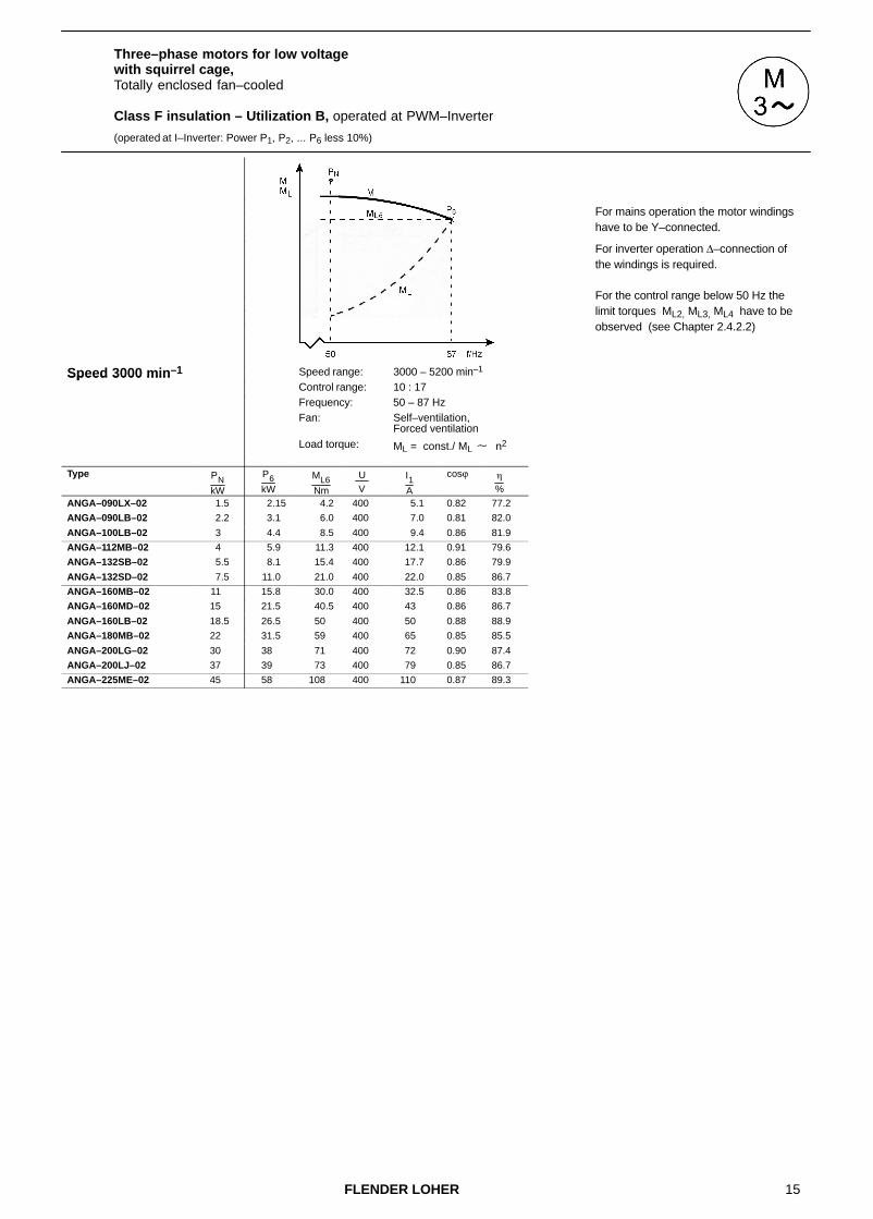
3.2 Three–phase motors for low voltage with squirrel cage,Totally enclosed fan–cooled
Class F insulation – Utilization B, operated at PWM–Inverter
(operated at I–Inverter: Power P1, P2, ... P6 less 10%)
Speed 3000 min–1 Speed range: 300 – 3000 min–1 Speed range: 1000 – 3000 min–1Speed 3000 minControl range: 1 : 10 Control range: 1 : 3Frequency: 5 – 50 Hz Frequency: 16.7 – 50 HzFan: Self–ventilation Fan: Self–ventilation
Load torque: ML � n2 Load torque: ML = const.
Type PNkW
P1kW
ML1Nm
U V
I1A
cosϕ �
%
P2kW
ML2Nm
U V
I1A
cosϕ �
%
ANGA–090LX–02 1.5 1.50 5.1 400 3.30 0.87 77.9 1.20 4.1 400 2.80 0.82 78.2
ANGA–090LB–02 2.2 2.20 7.4 400 4.65 0.86 81.7 1.75 5.9 400 3.90 0.82 81.9
ANGA–100LB–02 3 3.15 10.4 400 6.20 0.89 84.1 2.55 8.4 400 5.20 0.86 84.4
ANGA–112MB–02 4 4.20 13.9 400 8.00 0.93 84.1 3.90 12.9 400 7.40 0.92 84.3
ANGA–132SB–02 5.5 5.80 19.0 400 11.4 0.88 85.2 4.95 16.3 400 10.0 0.86 85.1
ANGA–132SD–02 7.5 7.80 25.5 400 14.7 0.88 88.4 6.30 20.5 400 12.4 0.85 88.5
ANGA–160MB–02 11 11.6 38 400 22 0.88 88.3 10.3 33.5 400 19.7 0.87 88.4
ANGA–160MD–02 15 15.0 49 400 28 0.88 89.7 12.1 39.5 400 23.5 0.85 89.8
ANGA–160LB–02 18.5 19.4 64 400 35 0.90 91.0 15.8 52 400 29 0.88 91.4
ANGA–180MB–02 22 23.0 75 400 43 0.87 90.7 21.0 68 400 40 0.86 90.6
ANGA–200LG–02 30 31.5 102 400 55 0.92 92.2 25.0 81 400 44 0.90 92.0
ANGA–200LJ–02 37 35 113 400 62 0.89 92.6 27.5 89 400 51 0.87 92.2
ANGA–225ME–02 45 47 152 400 82 0.90 93.4 38 123 400 68 0.88 93.2
ANGA–250ME–02 55 58 186 400 103 0.88 93.8 51 163 400 93 0.86 93.6
ANGA–280SG–02 1 75 77 245 400 128 0.93 94.7 61 196 400 102 0.92 94.6
ANGA–280MG–02 1 90 86 275 400 144 0.92 94.6 69 220 400 118 0.91 94.4
ANGA–315SL–02 110 105 335 400 180 0.90 94.8 89 285 400 156 0.89 94.5
ANGA–315ML–02 132 125 400 400 215 0.90 95.3 108 345 400 189 0.88 95.0
ANGA–315MN–02 160 152 485 400 255 0.91 96.0 130 415 400 220 0.89 95.8
ANGA–315LL–02 200 182 580 400 310 0.90 95.6 160 510 400 275 0.89 95.4
ANGA–315LN–02 2 250 215 690 400 355 0.93 96.1 179 570 400 300 0.92 95.9
ANGA–315LN–02 3 250 240 760 400 385 0.94 96.4 205 650 400 330 0.94 96.4
ANGA–355LB–02 2 315 275 890 400 460 0.90 96.6 230 740 400 390 0.88 96.5
ANGA–355LB–02 3 315 300 960 400 495 0.90 96.9 260 840 400 435 0.89 96.8
ANSA–355LC–02 355 335 1080 690 315 0.92 96.8 280 900 690 265 0.92 96.7
ANSA–355LD–02 400 380 1220 690 360 0.91 97.0 330 1060 690 320 0.90 96.9
ANSA–355LX–02 450 430 1370 690 410 0.91 96.5 350 1130 690 340 0.90 96.5
ANSA–400LN–02 500 475 1520 690 450 0.91 96.8 415 1330 690 395 0.91 96.7
ANSA–400LN–02 560 530 1700 690 500 0.91 96.9 450 1440 690 430 0.91 96.8
ANSA–400LX–02 630 600 1920 690 570 0.91 97.0 500 1610 690 475 0.91 96.9
ANSA–450LL–02 710 670 2150 690 630 0.91 96.9 570 1840 690 540 0.91 96.8
ANSA–450LN–02 800 760 2450 690 720 0.91 97.0 650 2050 690 620 0.90 96.9
ANSA–450LN–02 900 860 2750 690 810 0.91 97.2 740 2350 690 710 0.90 97.1
1 Special motor, inverter–optimized (different from Technical List IM)2 Rated power PN for utilization F3 Motor with special rotor (Cu)
13FLENDER LOHER
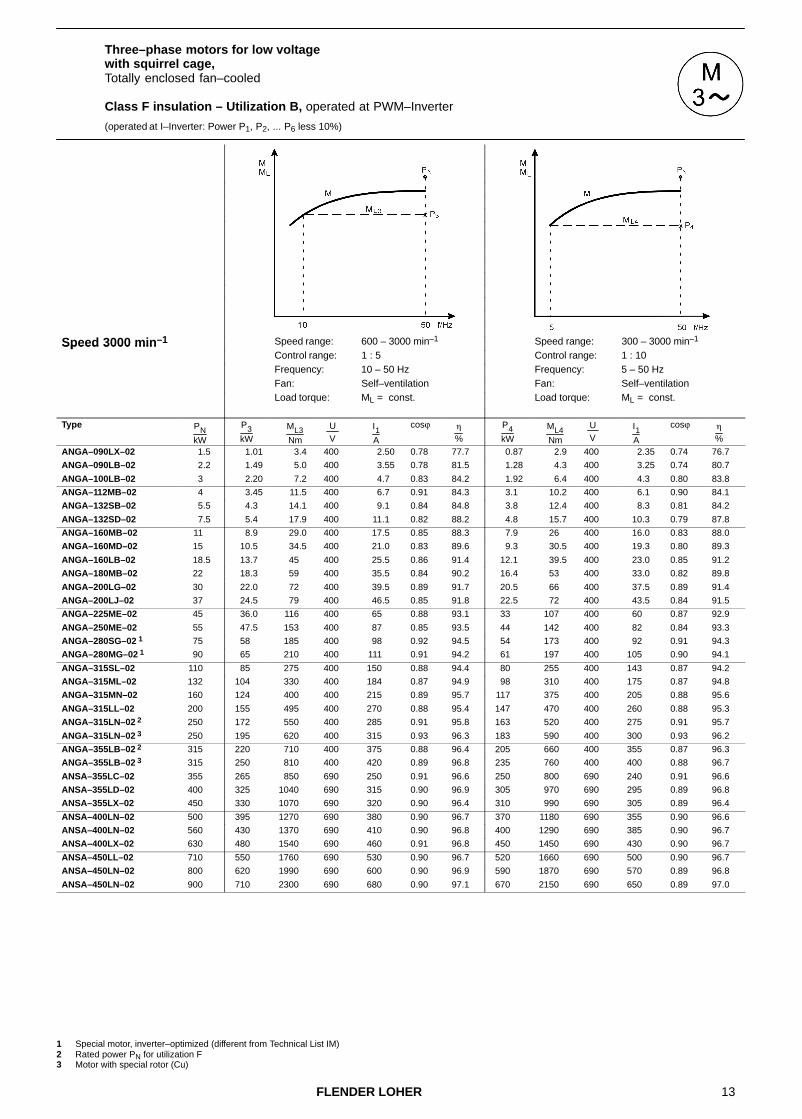
Three–phase motors for low voltage with squirrel cage,Totally enclosed fan–cooled
Class F insulation – Utilization B, operated at PWM–Inverter
(operated at I–Inverter: Power P1, P2, ... P6 less 10%)
Speed 3000 min–1 Speed range: 600 – 3000 min–1 Speed range: 300 – 3000 min–1Speed 3000 minControl range: 1 : 5 Control range: 1 : 10Frequency: 10 – 50 Hz Frequency: 5 – 50 HzFan: Self–ventilation Fan: Self–ventilation
Load torque: ML = const. Load torque: ML = const.
Type PNkW
P3kW
ML3Nm
U V
I1A
cosϕ �
%
P4kW
ML4Nm
U V
I1A
cosϕ �
%
ANGA–090LX–02 1.5 1.01 3.4 400 2.50 0.78 77.7 0.87 2.9 400 2.35 0.74 76.7
ANGA–090LB–02 2.2 1.49 5.0 400 3.55 0.78 81.5 1.28 4.3 400 3.25 0.74 80.7
ANGA–100LB–02 3 2.20 7.2 400 4.7 0.83 84.2 1.92 6.4 400 4.3 0.80 83.8
ANGA–112MB–02 4 3.45 11.5 400 6.7 0.91 84.3 3.1 10.2 400 6.1 0.90 84.1
ANGA–132SB–02 5.5 4.3 14.1 400 9.1 0.84 84.8 3.8 12.4 400 8.3 0.81 84.2
ANGA–132SD–02 7.5 5.4 17.9 400 11.1 0.82 88.2 4.8 15.7 400 10.3 0.79 87.8
ANGA–160MB–02 11 8.9 29.0 400 17.5 0.85 88.3 7.9 26 400 16.0 0.83 88.0
ANGA–160MD–02 15 10.5 34.5 400 21.0 0.83 89.6 9.3 30.5 400 19.3 0.80 89.3
ANGA–160LB–02 18.5 13.7 45 400 25.5 0.86 91.4 12.1 39.5 400 23.0 0.85 91.2
ANGA–180MB–02 22 18.3 59 400 35.5 0.84 90.2 16.4 53 400 33.0 0.82 89.8
ANGA–200LG–02 30 22.0 72 400 39.5 0.89 91.7 20.5 66 400 37.5 0.89 91.4
ANGA–200LJ–02 37 24.5 79 400 46.5 0.85 91.8 22.5 72 400 43.5 0.84 91.5
ANGA–225ME–02 45 36.0 116 400 65 0.88 93.1 33 107 400 60 0.87 92.9
ANGA–250ME–02 55 47.5 153 400 87 0.85 93.5 44 142 400 82 0.84 93.3
ANGA–280SG–02 1 75 58 185 400 98 0.92 94.5 54 173 400 92 0.91 94.3
ANGA–280MG–02 1 90 65 210 400 111 0.91 94.2 61 197 400 105 0.90 94.1
ANGA–315SL–02 110 85 275 400 150 0.88 94.4 80 255 400 143 0.87 94.2
ANGA–315ML–02 132 104 330 400 184 0.87 94.9 98 310 400 175 0.87 94.8
ANGA–315MN–02 160 124 400 400 215 0.89 95.7 117 375 400 205 0.88 95.6
ANGA–315LL–02 200 155 495 400 270 0.88 95.4 147 470 400 260 0.88 95.3
ANGA–315LN–02 2 250 172 550 400 285 0.91 95.8 163 520 400 275 0.91 95.7
ANGA–315LN–02 3 250 195 620 400 315 0.93 96.3 183 590 400 300 0.93 96.2
ANGA–355LB–02 2 315 220 710 400 375 0.88 96.4 205 660 400 355 0.87 96.3
ANGA–355LB–02 3 315 250 810 400 420 0.89 96.8 235 760 400 400 0.88 96.7
ANSA–355LC–02 355 265 850 690 250 0.91 96.6 250 800 690 240 0.91 96.6
ANSA–355LD–02 400 325 1040 690 315 0.90 96.9 305 970 690 295 0.89 96.8
ANSA–355LX–02 450 330 1070 690 320 0.90 96.4 310 990 690 305 0.89 96.4
ANSA–400LN–02 500 395 1270 690 380 0.90 96.7 370 1180 690 355 0.90 96.6
ANSA–400LN–02 560 430 1370 690 410 0.90 96.8 400 1290 690 385 0.90 96.7
ANSA–400LX–02 630 480 1540 690 460 0.91 96.8 450 1450 690 430 0.90 96.7
ANSA–450LL–02 710 550 1760 690 530 0.90 96.7 520 1660 690 500 0.90 96.7
ANSA–450LN–02 800 620 1990 690 600 0.90 96.9 590 1870 690 570 0.89 96.8
ANSA–450LN–02 900 710 2300 690 680 0.90 97.1 670 2150 690 650 0.89 97.0
1 Special motor, inverter–optimized (different from Technical List IM)2 Rated power PN for utilization F3 Motor with special rotor (Cu)

14 FLENDER LOHER
Three–phase motors for low voltage with squirrel cage,Totally enclosed fan–cooled
Class F insulation – Utilization B, operated at PWM–Inverter
(operated at I–Inverter: Power P1, P2, ... P6 less 10%)
Speed 3000 min–1 Speed range: 300 – 3000 min–1Speed 3000 minControl range: 1 : 10Frequency: 5 – 50 HzFan: Forced ventilation
Load torque: ML = const.
Type PNkW
P5kW
ML5Nm
U V
I1A
cosϕ �
%
ANLA–090LX–02 1.5 1.51 5.1 400 3.35 0.87 77.9
ANLA–090LB–02 2.2 2.20 7.4 400 4.65 0.86 81.7
ANLA–100LB–02 3 3.15 10.4 400 6.2 0.89 84.1
ANLA–112MB–02 4 4.2 13.9 400 8.0 0.93 84.1
ANLA–132SB–02 5.5 5.8 19.0 400 11.4 0.88 85.2
ANLA–132SD–02 7.5 7.8 25.5 400 14.7 0.88 88.4
ANLA–160MB–02 11 11.6 38 400 22 0.88 88.3
ANLA–160MD–02 15 15.0 49 400 28 0.88 89.7
ANLA–160LB–02 18.5 19.4 64 400 35 0.90 91.0
ANLA–180MB–02 22 23.0 75 400 43 0.87 90.7
ANLA–200LG–02 30 31.5 102 400 55 0.92 92.2
ANLA–200LJ–02 37 35 113 400 62 0.89 92.6
ANLA–225ME–02 45 47 152 400 82 0.90 93.4
ANLA–250ME–02 55 58 186 400 103 0.88 93.8
ANLA–280SG–02 1 75 76 245 400 127 0.93 94.7
ANLA–280MG–02 1 90 86 275 400 144 0.92 94.6
ANLA–315SL–02 110 104 335 400 178 0.90 94.8
ANLA–315ML–02 132 125 400 400 215 0.90 95.3
ANLA–315MN–02 160 151 485 400 255 0.91 95.9
ANLA–315LL–02 200 181 580 400 305 0.90 95.6
ANLA–315LN–02 2 250 215 690 400 355 0.93 96.1
ANLA–315LN–02 3 250 240 760 400 385 0.94 96.4
ANLA–355LB–02 2 315 280 890 400 465 0.90 96.6
ANLA–355LB–02 3 315 300 960 400 495 0.90 96.9
ANUA–355LC–02 355 335 1080 690 315 0.92 96.8
ANUA–355LD–02 400 380 1220 690 360 0.91 97.0
ANUA–355LX–02 450 415 1330 690 395 0.91 96.5
ANUA–400LN–02 500 460 1470 690 440 0.91 96.8
ANUA–400LN–02 560 520 1650 690 495 0.91 96.9
ANUA–400LX–02 630 580 1860 690 550 0.91 96.9
ANUA–450LL–02 710 650 2100 690 620 0.91 96.9
ANUA–450LN–02 800 740 2350 690 710 0.91 97.0
ANUA–450LN–02 900 830 2650 690 790 0.91 97.2
1 Special motor, inverter–optimized (different from Technical List IM)2 Rated power PN for utilization F3 Motor with special rotor (Cu)
15FLENDER LOHER
Three–phase motors for low voltage with squirrel cage,Totally enclosed fan–cooled
Class F insulation – Utilization B, operated at PWM–Inverter
(operated at I–Inverter: Power P1, P2, ... P6 less 10%)
Speed 3000 min–1 Speed range: 3000 – 5200 min–1Speed 3000 minControl range: 10 : 17Frequency: 50 – 87 HzFan: Self–ventilation,
Forced ventilationLoad torque: ML = const./ ML � n2
Type PNkW
P6kW
ML6Nm
U V
I1A
cosϕ �
%
ANGA–090LX–02 1.5 2.15 4.2 400 5.1 0.82 77.2
ANGA–090LB–02 2.2 3.1 6.0 400 7.0 0.81 82.0
ANGA–100LB–02 3 4.4 8.5 400 9.4 0.86 81.9
ANGA–112MB–02 4 5.9 11.3 400 12.1 0.91 79.6
ANGA–132SB–02 5.5 8.1 15.4 400 17.7 0.86 79.9
ANGA–132SD–02 7.5 11.0 21.0 400 22.0 0.85 86.7
ANGA–160MB–02 11 15.8 30.0 400 32.5 0.86 83.8
ANGA–160MD–02 15 21.5 40.5 400 43 0.86 86.7
ANGA–160LB–02 18.5 26.5 50 400 50 0.88 88.9
ANGA–180MB–02 22 31.5 59 400 65 0.85 85.5
ANGA–200LG–02 30 38 71 400 72 0.90 87.4
ANGA–200LJ–02 37 39 73 400 79 0.85 86.7
ANGA–225ME–02 45 58 108 400 110 0.87 89.3
For mains operation the motor windings have to be Y–connected.
For inverter operation ∆–connection of the windings is required.
For the control range below 50 Hz the limit torques ML2, ML3, ML4 have to be observed (see Chapter 2.4.2.2)

16 FLENDER LOHER
Three–phase motors for low voltage with squirrel cage,Totally enclosed fan–cooled
Class F insulation – Utilization B, operated at PWM–Inverter
(operated at I–Inverter: Power P1, P2, ... P6 less 10%)
Speed 1500 min–1 Speed range: 150 – 1500 min–1 Speed range: 500 – 1500 min–1Speed 1500 minControl range: 1 : 10 Control range: 1 : 3Frequency: 5 – 50 Hz Frequency: 16.7 – 50 HzFan: Self–ventilation Fan: Self–ventilation
Load torque: ML � n2 Load torque: ML = const.
Type PNkW
P1kW
ML1Nm
U V
I1A
cosϕ �
%
P2kW
ML2Nm
U V
I1A
cosϕ �
%
ANGA–090LX–04 1.1 1.15 7.8 400 2.55 0.87 77.8 0.96 6.5 400 2.20 0.84 78.6
ANGA–090LB–04 1.5 1.57 10.7 400 3.55 0.87 76.6 1.30 8.9 400 3.05 0.83 77.4
ANGA–100LB–04 2.2 2.3 15.7 400 5.1 0.86 78.2 1.83 12.5 400 4.25 0.82 79.0
ANGA–100LD–04 3 3.0 20.5 400 6.9 0.81 80.6 2.30 15.7 400 5.8 0.74 80.8
ANGA–112MB–04 4 4.0 27.0 400 8.3 0.87 83.3 3.20 21.5 400 6.8 0.83 84.0
ANGA–132SB–04 5.5 5.8 38.5 400 11.4 0.88 86.3 4.85 32.5 400 9.7 0.85 86.8
ANGA–132MB–04 7.5 7.8 52 400 15.2 0.86 87.9 6.3 41.5 400 12.7 0.83 88.4
ANGA–160MB–04 11 11.5 75 400 22.5 0.86 89.3 9.3 61 400 18.5 0.83 89.7
ANGA–160LB–04 15 15.0 98 400 29.0 0.85 90.5 12.0 79 400 24.0 0.82 91.0
ANGA–180MB–04 18.5 19.1 125 400 35.5 0.87 91.1 15.7 103 400 30.0 0.85 91.3
ANGA–180LB–04 22 23.0 151 400 42.5 0.87 91.5 19.5 127 400 36.5 0.86 91.8
ANGA–200LG–04 30 30.0 197 400 54 0.88 92.3 24.0 155 400 44 0.87 92.6
ANGA–225SE–04 37 35.5 230 400 64 0.88 93.3 29.0 189 400 53 0.86 93.5
ANGA–225ME–04 45 43.5 280 400 81 0.85 93.4 35.5 230 400 68 0.82 93.5
ANGA–250ME–04 55 54 350 400 95 0.88 94.0 46.5 300 400 84 0.87 93.9
ANGA–280SG–04 75 75 485 400 132 0.88 94.7 62 400 400 111 0.87 94.7
ANGA–280MG–04 90 86 550 400 150 0.88 94.9 73 470 400 129 0.87 94.8
ANGA–315SL–04 110 104 670 400 190 0.85 95.2 94 600 400 174 0.83 95.2
ANGA–315ML–04 132 125 810 400 225 0.86 95.4 108 690 400 196 0.85 95.4
ANGA–315MN–04 160 152 980 400 270 0.86 95.7 129 830 400 235 0.84 95.7
ANGA–315LL–04 2 200 175 1130 400 320 0.84 95.7 148 950 400 280 0.82 95.6
ANGA–315LL–04 3 200 190 1220 400 340 0.86 95.8 167 1070 400 305 0.85 95.7
ANGA–315LM–04 2 250 220 1400 400 405 0.83 96.3 181 1160 400 345 0.80 96.2
ANGA–315LM–04 3 250 235 1520 400 420 0.85 96.0 210 1340 400 385 0.84 96.0
ANGA–355LB–04 270 250 1610 400 445 0.84 96.5 220 1400 400 400 0.83 96.4
ANGA–355LB–04 3 315 300 1920 400 520 0.86 96.4 265 1700 400 470 0.85 96.3
ANSA–355LC–04 355 335 2150 690 340 0.86 96.8 300 1910 690 305 0.85 96.7
ANSA–355LD–04 400 380 2450 690 380 0.86 96.9 335 2150 690 340 0.85 96.8
ANSA–355LN–04 450 430 2750 690 440 0.85 96.7 380 2400 690 390 0.84 96.7
ANSA–355LX–04 500 475 3050 690 480 0.85 96.9 420 2700 690 430 0.84 96.9
ANSA–400LN–04 560 530 3400 690 520 0.88 96.9 470 3000 690 470 0.87 96.8
ANSA–400LN–04 630 600 3850 690 590 0.88 96.8 530 3400 690 530 0.87 96.8
ANSA–400LX–04 710 670 4300 690 660 0.88 97.0 590 3800 690 590 0.87 97.0
ANSA–450LL–04 800 760 4850 690 750 0.88 97.1 670 4300 690 670 0.87 97.0
ANSA–450LN–04 900 860 5500 690 840 0.88 97.2 760 4850 690 750 0.87 97.1
ANSA–450LN–04 950 900 5800 690 880 0.88 97.3 800 5100 690 790 0.87 97.2
ANSA–500LL–04 1000 950 6100 690 930 0.88 97.0 840 5400 690 830 0.87 96.9
ANSA–500LL–04 1120 1060 6800 690 1040 0.88 97.2 940 6000 690 920 0.88 97.1
2 Rated power PN for utilization F3 Motor with special rotor (Cu)

17FLENDER LOHER
Three–phase motors for low voltage with squirrel cage,Totally enclosed fan–cooled
Class F insulation – Utilization B, operated at PWM–Inverter
(operated at I–Inverter: Power P1, P2, ... P6 less 10%)
Speed 1500 min–1 Speed range: 300 – 1500 min–1 Speed range: 150 – 1500 min–1Speed 1500 minControl range: 1 : 5 Control range: 1 : 10Frequency: 10 – 50 Hz Frequency: 5 – 50 HzFan: Self–ventilation Fan: Self–ventilation
Load torque: ML = const. Load torque: ML = const.
Type PNkW
P3kW
ML3Nm
U V
I1A
cosϕ �
%
P4kW
ML4Nm
U V
I1A
cosϕ �
%
ANGA–090LX–04 1.1 0.84 5.7 400 1.99 0.81 78.6 0.77 5.2 400 1.88 0.79 78.4
ANGA–090LB–04 1.5 1.14 7.8 400 2.8 0.80 77.3 1.05 7.1 400 2.65 0.78 77.1
ANGA–100LB–04 2.2 1.67 11.4 400 4.0 0.80 78.9 1.54 10.5 400 3.8 0.78 78.7
ANGA–100LD–04 3 2.1 14.1 400 5.5 0.72 80.5 1.90 12.9 400 5.3 0.69 80.1
ANGA–112MB–04 4 2.9 19.8 400 6.3 0.81 84.0 2.70 18.4 400 6.0 0.80 83.9
ANGA–132SB–04 5.5 4.2 28 400 8.6 0.83 86.9 3.85 25.5 400 8.1 0.82 86.8
ANGA–132MB–04 7.5 5.7 38 400 11.8 0.81 88.4 5.2 35.0 400 11.1 0.79 88.3
ANGA–160MB–04 11 8.4 55 400 17.1 0.82 89.7 7.4 48.5 400 15.5 0.79 89.6
ANGA–160LB–04 15 11.1 73 400 22.5 0.81 91.0 10.0 66 400 21.0 0.79 91.0
ANGA–180MB–04 18.5 14.1 92 400 27.5 0.83 91.3 12.4 81 400 25.0 0.81 91.1
ANGA–180LB–04 22 16.7 109 400 32.0 0.84 91.9 14.7 96 400 29.0 0.82 91.8
ANGA–200LG–04 30 22.0 145 400 40.5 0.86 92.6 20.0 131 400 37.5 0.85 92.5
ANGA–225SE–04 37 29.0 187 400 53 0.86 93.5 26.5 171 400 49 0.85 93.5
ANGA–225ME–04 45 35.0 230 400 68 0.82 93.5 32.0 210 400 63 0.81 93.4
ANGA–250ME–04 55 46.5 300 400 84 0.87 93.9 42.5 275 400 78 0.86 93.8
ANGA–280SG–04 75 62 400 400 111 0.87 94.7 57 370 400 103 0.86 94.6
ANGA–280MG–04 90 73 470 400 129 0.87 94.8 68 435 400 122 0.87 94.7
ANGA–315SL–04 110 93 600 400 173 0.83 95.2 86 550 400 162 0.82 95.1
ANGA–315ML–04 132 107 690 400 195 0.85 95.3 101 650 400 186 0.84 95.3
ANGA–315MN–04 160 129 830 400 235 0.84 95.7 119 770 400 220 0.83 95.6
ANGA–315LL–04 2 200 148 950 400 280 0.82 95.6 137 880 400 260 0.81 95.5
ANGA–315LL–04 3 200 167 1070 400 305 0.85 95.7 155 1000 400 285 0.84 95.7
ANGA–315LM–04 2 250 180 1160 400 345 0.80 96.2 168 1080 400 330 0.79 96.2
ANGA–315LM–04 3 250 210 1340 400 385 0.84 96.0 195 1250 400 360 0.83 95.9
ANGA–355LB–04 270 220 1400 400 400 0.83 96.4 205 1320 400 375 0.82 96.4
ANGA–355LB–04 3 315 260 1650 400 460 0.85 96.3 245 1550 400 440 0.84 96.2
ANSA–355LC–04 355 290 1860 690 300 0.84 96.7 275 1750 690 285 0.84 96.7
ANSA–355LD–04 400 330 2100 690 335 0.85 96.8 310 1970 690 320 0.84 96.8
ANSA–355LN–04 450 370 2350 690 385 0.84 96.7 345 2200 690 360 0.83 96.6
ANSA–355LX–04 500 410 2650 690 425 0.84 96.8 385 2450 690 400 0.83 96.8
ANSA–400LN–04 560 460 2950 690 460 0.87 96.8 430 2750 690 435 0.86 96.8
ANSA–400LN–04 630 520 3300 690 520 0.87 96.7 485 3100 690 490 0.86 96.7
ANSA–400LX–04 710 580 3750 690 580 0.87 97.0 550 3500 690 550 0.86 97.0
ANSA–450LL–04 800 660 4200 690 660 0.87 97.0 620 3950 690 620 0.86 96.9
ANSA–450LN–04 900 740 4700 690 740 0.87 97.1 690 4450 690 690 0.86 97.0
ANSA–450LN–04 950 780 5000 690 770 0.87 97.2 730 4700 690 730 0.87 97.1
ANSA–500LL–04 1000 820 5200 690 810 0.87 96.9 770 4900 690 770 0.87 96.8
ANSA–500LL–04 1120 920 5900 690 910 0.88 97.1 860 5500 690 850 0.87 97.0
2 Rated power PN for utilization F3 Motor with special rotor (Cu)

18 FLENDER LOHER
Three–phase motors for low voltage with squirrel cage,Totally enclosed fan–cooled
Class F insulation – Utilization B, operated at PWM–Inverter
(operated at I–Inverter: Power P1, P2, ... P6 less 10%)
Speed 1500 min–1 Speed range: 150 – 1500 min–1Speed 1500 minControl range: 1 : 10Frequency: 5 – 50 HzFan: Forced ventilation
Load torque: ML = const.
Type PNkW
P5kW
ML5Nm
U V
I1A
cosϕ �
%
ANLA–090LX–04 1.1 1.15 7.8 400 2.55 0.87 77.8
ANLA–090LB–04 1.5 1.57 10.7 400 3.55 0.87 76.6
ANLA–100LB–04 2.2 2.3 15.7 400 5.1 0.86 78.2
ANLA–100LD–04 3 3.0 20.5 400 6.9 0.81 80.6
ANLA–112MB–04 4 4.0 27.0 400 8.3 0.87 83.3
ANLA–132SB–04 5.5 5.8 38.5 400 11.4 0.88 86.3
ANLA–132MB–04 7.5 7.8 52 400 15.2 0.86 87.9
ANLA–160MB–04 11 11.4 75 400 22.0 0.86 89.3
ANLA–160LB–04 15 14.9 98 400 29.0 0.85 90.5
NLA–180MB–04 18.5 19.2 125 400 36.0 0.87 91.1
ANLA–180LB–04 22 23.0 151 400 42.5 0.87 91.5
ANLA–200LG–04 30 30.0 197 400 54 0.88 92.3
ANLA–225SE–04 37 35.5 230 400 64 0.88 93.3
ANLA–225ME–04 45 43 280 400 80 0.85 93.4
ANLA–250ME–04 55 54 350 400 95 0.88 94.0
ANLA–280SG–04 75 75 485 400 132 0.88 94.7
ANLA–280MG–04 90 85 550 400 149 0.88 94.9
ANLA–315SL–04 110 104 670 400 190 0.85 95.2
ANLA–315ML–04 132 125 810 400 225 0.86 95.4
ANLA–315MN–04 160 152 980 400 270 0.86 95.7
ANLA–315LL–04 2 200 176 1130 400 320 0.84 95.7
ANLA–315LL–04 200 190 1220 400 340 0.86 95.8
ANLA–315LM–04 2 250 220 1400 400 405 0.83 96.3
ANLA–315LM–04 250 235 1520 400 420 0.85 96.0
ANLA–355LB–04 270 250 1610 400 445 0.84 96.5
ANLA–355LB–04 3 315 300 1920 400 520 0.86 96.4
ANUA–355LC–04 355 335 2150 690 340 0.86 96.8
ANUA–355LD–04 400 380 2450 690 380 0.86 96.9
ANUA–355LN–04 450 415 2650 690 425 0.85 96.7
ANUA–355LX–04 500 460 2950 690 470 0.85 96.9
ANUA–400LN–04 560 520 3300 690 510 0.88 96.9
ANUA–400LN–04 630 580 3700 690 570 0.87 96.8
ANUA–400LX–04 710 650 4200 690 640 0.88 97.0
ANUA–450LL–04 800 740 4700 690 730 0.88 97.0
ANUA–450LN–04 900 830 5300 690 820 0.88 97.1
ANUA–450LN–04 950 870 5600 690 850 0.88 97.3
ANUA–500LL–04 1000 920 5900 690 900 0.88 97.0
ANUA–500LL–04 1120 1030 6600 690 1010 0.88 97.2
2 Rated power PN for utilization F3 Motor with special rotor (Cu)

19FLENDER LOHER
Three–phase motors for low voltage with squirrel cage,Totally enclosed fan–cooled
Class F insulation – Utilization B, operated at PWM–Inverter
(operated at I–Inverter: Power P1, P2, ... P6 less 10%)
Speed 1500 min–1 Speed range: 1500 – 2600 min–1Speed 1500 minControl range: 10 : 17Frequency: 50 – 87 HzFan: Self–ventilation,
Forced ventilationLoad torque: ML = const./ ML � n2
Type PNkW
P6kW
ML6Nm
U V
I1A
cosϕ �
%
ANGA–090LX–04 1.1 1.60 6.3 400 3.75 0.81 79.3
ANGA–090LB–04 1.5 2.20 8.6 400 5.2 0.80 79.9
ANGA–100LB–04 2.2 3.20 12.6 400 7.4 0.80 81.1
ANGA–100LD–04 3 4.25 16.7 400 10.5 0.74 83.1
ANGA–112MB–04 4 5.8 23.0 400 12.3 0.83 84.4
ANGA–132SB–04 5.5 8.0 30.5 400 16.2 0.84 87.0
ANGA–132MB–04 7.5 10.9 42 400 22.0 0.82 89.4
ANGA–160MB–04 11 15.6 59 400 31.5 0.82 88.8
ANGA–160LB–04 15 21.5 81 400 42.5 0.82 91.8
ANGA–180MB–04 18.5 26.5 99 400 52 0.84 90.6
ANGA–180LB–04 22 31.0 118 400 60 0.84 91.4
ANGA–200LG–04 30 41.0 154 400 76 0.87 91.7
ANGA–225SE–04 37 46.5 175 400 87 0.85 92.3
ANGA–225ME–04 45 55 205 400 110 0.80 92.2
ANGA–250ME–04 55 63 235 400 121 0.84 91.9
ANGA–280SG–04 75 90 335 400 168 0.85 92.9
ANGA–280MG–04 90 99 365 400 186 0.85 92.7
ANGA–315SL–04 110 124 460 400 250 0.79 92.8
ANGA–315ML–04 132 138 510 400 270 0.81 93.2
ANGA–315MN–04 160 179 670 400 345 0.81 94.3
ANGA–315LL–04 2 200 196 730 400 400 0.78 93.4
ANGA–315LL–04 3 200 215 800 400 425 0.80 93.6
ANGA–315LM–04 2 250 245 910 400 510 0.75 95.1
ANGA–315LL–04 3 250 265 990 400 530 0.79 94.2
2 Rated power PN for utilization F3 Motor with special rotor (Cu)
For mains operation the motor windings have to be Y–connected.
For inverter operation ∆–connection of the windings is required.
For the control range below 50 Hz the limit torques ML2, ML3, ML4 have to be observed (see Chapter 2.4.2.2)

20 FLENDER LOHER
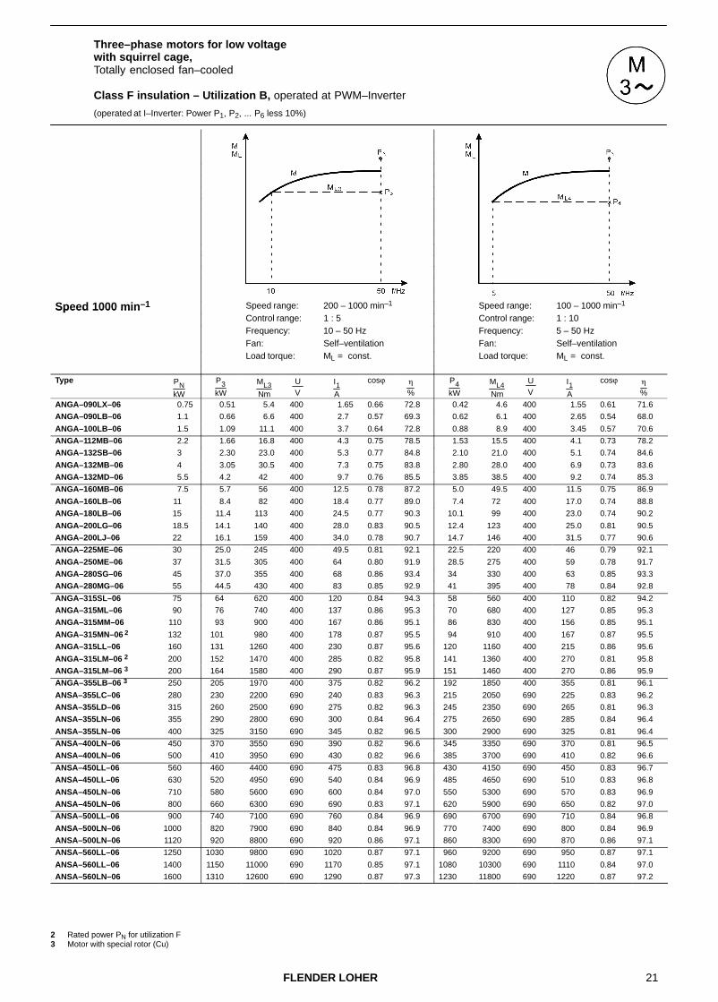
Three–phase motors for low voltage with squirrel cage,Totally enclosed fan–cooled
Class F insulation – Utilization B, operated at PWM–Inverter
(operated at I–Inverter: Power P1, P2, ... P6 less 10%)
Speed 1000 min–1 Speed range: 100 – 1000 min–1 Speed range: 330 – 1000 min–1Speed 1000 minControl range: 1 : 10 Control range: 1 : 3Frequency: 5 – 50 Hz Frequency: 16.7 – 50 HzFan: Self–ventilation Fan: Self–ventilation
Load torque: ML � n2 Load torque: ML = const.
Type PNkW
P1kW
ML1Nm
U V
I1A
cosϕ �
%
P2kW
ML2Nm
U V
I1A
cosϕ �
%
ANGA–090LX–06 0.75 0.78 8.3 400 2.1 0.79 71.4 0.58 6.2 400 1.74 0.70 73.0
ANGA–090LB–06 1.1 1.10 11.5 400 3.3 0.73 70.9 0.73 7.6 400 2.8 0.59 70.1
ANGA–100LB–06 1.5 1.57 16.0 400 4.4 0.74 74.2 1.26 12.8 400 3.9 0.68 73.7
ANGA–112MB–06 2.2 2.30 23.5 400 5.5 0.81 77.9 1.83 18.6 400 4.6 0.77 78.6
ANGA–132SB–06 3 3.15 31.5 400 6.7 0.83 84.6 2.9 29 400 6.3 0.81 84.8
ANGA–132MB–06 4 4.2 42 400 9.2 0.82 83.5 3.7 37 400 8.3 0.80 83.8
ANGA–132MD–06 5.5 5.8 58 400 12.3 0.83 85.1 5.1 51 400 11.1 0.80 85.5
ANGA–160MB–06 7.5 7.9 78 400 16.0 0.84 87.2 7.3 72 400 15.0 0.83 87.3
ANGA–160LB–06 11 11.5 113 400 23.0 0.83 88.9 10.2 100 400 21.0 0.81 89.1
ANGA–180LB–06 15 15.7 156 400 31.5 0.82 89.7 13.4 133 400 27.5 0.80 90.1
ANGA–200LG–06 18.5 19.4 193 400 38 0.85 89.5 16.6 165 400 32.5 0.84 90.2
ANGA–200LJ–06 22 22.5 220 400 45 0.82 90.2 17.3 171 400 35.5 0.80 90.7
ANGA–225ME–06 30 30.5 300 400 59 0.83 92.0 25.0 245 400 49.5 0.81 92.1
ANGA–250ME–06 37 39.0 375 400 77 0.82 92.1 33.5 325 400 67 0.81 92.0
ANGA–280SG–06 45 44.5 430 400 80 0.88 93.3 37 360 400 68 0.86 93.4
ANGA–280MG–06 55 53 510 400 97 0.87 93.0 44 430 400 82 0.85 92.9
ANGA–315SL–06 75 71 690 400 131 0.85 94.3 64 620 400 120 0.84 94.3
ANGA–315ML–06 90 85 830 400 151 0.87 95.3 77 750 400 138 0.86 95.3
ANGA–315MM–06 110 104 1010 400 185 0.87 95.1 95 910 400 170 0.86 95.1
ANGA–315MN–06 2 132 118 1140 400 205 0.88 95.5 102 980 400 179 0.87 95.5
ANGA–315LL–06 160 152 1470 400 265 0.88 95.6 131 1270 400 230 0.87 95.6
ANGA–315LM–06 2 200 177 1700 400 325 0.84 95.9 152 1470 400 285 0.82 95.8
ANGA–315LM–06 3 200 190 1830 400 330 0.88 95.9 164 1580 400 290 0.87 95.9
ANGA–355LB–06 3 250 235 2300 400 420 0.84 96.3 210 2000 400 385 0.82 96.2
ANSA–355LC–06 280 265 2550 690 270 0.85 96.3 235 2250 690 245 0.84 96.3
ANSA–355LD–06 315 300 2900 690 310 0.84 96.4 265 2550 690 280 0.82 96.3
ANSA–355LN–06 355 335 3250 690 340 0.85 96.4 295 2850 690 305 0.84 96.4
ANSA–355LN–06 400 380 3650 690 395 0.83 96.5 325 3150 690 345 0.82 96.5
ANSA–400LN–06 450 425 4100 690 440 0.84 96.6 380 3650 690 400 0.83 96.6
ANSA–400LN–06 500 475 4550 690 490 0.84 96.7 415 4000 690 435 0.83 96.6
ANSA–450LL–06 560 530 5100 690 540 0.85 96.9 470 4500 690 485 0.84 96.8
ANSA–450LL–06 630 600 5700 690 610 0.85 97.0 530 5100 690 550 0.84 96.9
ANSA–450LN–06 710 670 6500 690 680 0.85 97.0 600 5700 690 620 0.84 97.0
ANSA–450LN–06 800 740 7100 690 760 0.84 97.1 650 6300 690 680 0.83 97.1
ANSA–500LL–06 900 860 8200 690 880 0.85 97.0 760 7300 690 780 0.84 96.9
ANSA–500LN–06 1000 950 9100 690 970 0.85 97.1 840 8100 690 860 0.84 97.0
ANSA–500LN–06 1120 1060 10200 690 1060 0.86 97.2 940 9000 690 940 0.86 97.1
ANSA–560LL–06 1250 1190 11400 690 1170 0.88 97.2 1050 10100 690 1040 0.87 97.2
ANSA–560LL–06 1400 1330 12800 690 1330 0.86 97.2 1180 11300 690 1200 0.85 97.1
ANSA–560LN–06 1600 1520 14600 690 1490 0.88 97.4 1340 12900 690 1320 0.87 97.3
2 Rated power PN for utilization F3 Motor with special rotor (Cu)
21FLENDER LOHER
Three–phase motors for low voltage with squirrel cage,Totally enclosed fan–cooled
Class F insulation – Utilization B, operated at PWM–Inverter
(operated at I–Inverter: Power P1, P2, ... P6 less 10%)
Speed 1000 min–1 Speed range: 200 – 1000 min–1 Speed range: 100 – 1000 min–1Speed 1000 minControl range: 1 : 5 Control range: 1 : 10Frequency: 10 – 50 Hz Frequency: 5 – 50 HzFan: Self–ventilation Fan: Self–ventilation
Load torque: ML = const. Load torque: ML = const.
Type PNkW
P3kW
ML3Nm
U V
I1A
cosϕ �
%
P4kW
ML4Nm
U V
I1A
cosϕ �
%
ANGA–090LX–06 0.75 0.51 5.4 400 1.65 0.66 72.8 0.42 4.6 400 1.55 0.61 71.6
ANGA–090LB–06 1.1 0.66 6.6 400 2.7 0.57 69.3 0.62 6.1 400 2.65 0.54 68.0
ANGA–100LB–06 1.5 1.09 11.1 400 3.7 0.64 72.8 0.88 8.9 400 3.45 0.57 70.6
ANGA–112MB–06 2.2 1.66 16.8 400 4.3 0.75 78.5 1.53 15.5 400 4.1 0.73 78.2
ANGA–132SB–06 3 2.30 23.0 400 5.3 0.77 84.8 2.10 21.0 400 5.1 0.74 84.6
ANGA–132MB–06 4 3.05 30.5 400 7.3 0.75 83.8 2.80 28.0 400 6.9 0.73 83.6
ANGA–132MD–06 5.5 4.2 42 400 9.7 0.76 85.5 3.85 38.5 400 9.2 0.74 85.3
ANGA–160MB–06 7.5 5.7 56 400 12.5 0.78 87.2 5.0 49.5 400 11.5 0.75 86.9
ANGA–160LB–06 11 8.4 82 400 18.4 0.77 89.0 7.4 72 400 17.0 0.74 88.8
ANGA–180LB–06 15 11.4 113 400 24.5 0.77 90.3 10.1 99 400 23.0 0.74 90.2
ANGA–200LG–06 18.5 14.1 140 400 28.0 0.83 90.5 12.4 123 400 25.0 0.81 90.5
ANGA–200LJ–06 22 16.1 159 400 34.0 0.78 90.7 14.7 146 400 31.5 0.77 90.6
ANGA–225ME–06 30 25.0 245 400 49.5 0.81 92.1 22.5 220 400 46 0.79 92.1
ANGA–250ME–06 37 31.5 305 400 64 0.80 91.9 28.5 275 400 59 0.78 91.7
ANGA–280SG–06 45 37.0 355 400 68 0.86 93.4 34 330 400 63 0.85 93.3
ANGA–280MG–06 55 44.5 430 400 83 0.85 92.9 41 395 400 78 0.84 92.8
ANGA–315SL–06 75 64 620 400 120 0.84 94.3 58 560 400 110 0.82 94.2
ANGA–315ML–06 90 76 740 400 137 0.86 95.3 70 680 400 127 0.85 95.3
ANGA–315MM–06 110 93 900 400 167 0.86 95.1 86 830 400 156 0.85 95.1
ANGA–315MN–06 2 132 101 980 400 178 0.87 95.5 94 910 400 167 0.87 95.5
ANGA–315LL–06 160 131 1260 400 230 0.87 95.6 120 1160 400 215 0.86 95.6
ANGA–315LM–06 2 200 152 1470 400 285 0.82 95.8 141 1360 400 270 0.81 95.8
ANGA–315LM–06 3 200 164 1580 400 290 0.87 95.9 151 1460 400 270 0.86 95.9
ANGA–355LB–06 3 250 205 1970 400 375 0.82 96.2 192 1850 400 355 0.81 96.1
ANSA–355LC–06 280 230 2200 690 240 0.83 96.3 215 2050 690 225 0.83 96.2
ANSA–355LD–06 315 260 2500 690 275 0.82 96.3 245 2350 690 265 0.81 96.3
ANSA–355LN–06 355 290 2800 690 300 0.84 96.4 275 2650 690 285 0.84 96.4
ANSA–355LN–06 400 325 3150 690 345 0.82 96.5 300 2900 690 325 0.81 96.4
ANSA–400LN–06 450 370 3550 690 390 0.82 96.6 345 3350 690 370 0.81 96.5
ANSA–400LN–06 500 410 3950 690 430 0.82 96.6 385 3700 690 410 0.82 96.6
ANSA–450LL–06 560 460 4400 690 475 0.83 96.8 430 4150 690 450 0.83 96.7
ANSA–450LL–06 630 520 4950 690 540 0.84 96.9 485 4650 690 510 0.83 96.8
ANSA–450LN–06 710 580 5600 690 600 0.84 97.0 550 5300 690 570 0.83 96.9
ANSA–450LN–06 800 660 6300 690 690 0.83 97.1 620 5900 690 650 0.82 97.0
ANSA–500LL–06 900 740 7100 690 760 0.84 96.9 690 6700 690 710 0.84 96.8
ANSA–500LN–06 1000 820 7900 690 840 0.84 96.9 770 7400 690 800 0.84 96.9
ANSA–500LN–06 1120 920 8800 690 920 0.86 97.1 860 8300 690 870 0.86 97.1
ANSA–560LL–06 1250 1030 9800 690 1020 0.87 97.1 960 9200 690 950 0.87 97.1
ANSA–560LL–06 1400 1150 11000 690 1170 0.85 97.1 1080 10300 690 1110 0.84 97.0
ANSA–560LN–06 1600 1310 12600 690 1290 0.87 97.3 1230 11800 690 1220 0.87 97.2
2 Rated power PN for utilization F3 Motor with special rotor (Cu)
22 FLENDER LOHER
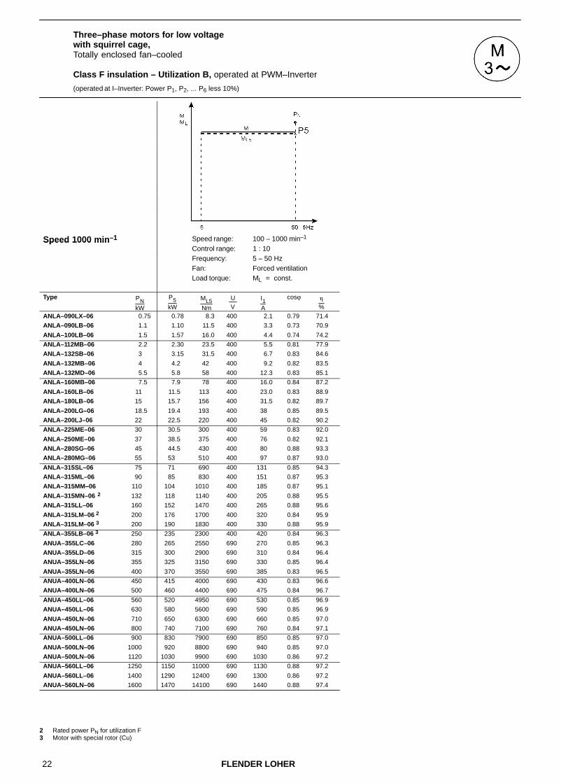
Three–phase motors for low voltage with squirrel cage,Totally enclosed fan–cooled
Class F insulation – Utilization B, operated at PWM–Inverter
(operated at I–Inverter: Power P1, P2, ... P6 less 10%)
Speed 1000 min–1 Speed range: 100 – 1000 min–1Speed 1000 minControl range: 1 : 10Frequency: 5 – 50 HzFan: Forced ventilation
Load torque: ML = const.
Type PNkW
P5kW
ML5Nm
U V
I1A
cosϕ �
%
ANLA–090LX–06 0.75 0.78 8.3 400 2.1 0.79 71.4
ANLA–090LB–06 1.1 1.10 11.5 400 3.3 0.73 70.9
ANLA–100LB–06 1.5 1.57 16.0 400 4.4 0.74 74.2
ANLA–112MB–06 2.2 2.30 23.5 400 5.5 0.81 77.9
ANLA–132SB–06 3 3.15 31.5 400 6.7 0.83 84.6
ANLA–132MB–06 4 4.2 42 400 9.2 0.82 83.5
ANLA–132MD–06 5.5 5.8 58 400 12.3 0.83 85.1
ANLA–160MB–06 7.5 7.9 78 400 16.0 0.84 87.2
ANLA–160LB–06 11 11.5 113 400 23.0 0.83 88.9
ANLA–180LB–06 15 15.7 156 400 31.5 0.82 89.7
ANLA–200LG–06 18.5 19.4 193 400 38 0.85 89.5
ANLA–200LJ–06 22 22.5 220 400 45 0.82 90.2
ANLA–225ME–06 30 30.5 300 400 59 0.83 92.0
ANLA–250ME–06 37 38.5 375 400 76 0.82 92.1
ANLA–280SG–06 45 44.5 430 400 80 0.88 93.3
ANLA–280MG–06 55 53 510 400 97 0.87 93.0
ANLA–315SL–06 75 71 690 400 131 0.85 94.3
ANLA–315ML–06 90 85 830 400 151 0.87 95.3
ANLA–315MM–06 110 104 1010 400 185 0.87 95.1
ANLA–315MN–06 2 132 118 1140 400 205 0.88 95.5
ANLA–315LL–06 160 152 1470 400 265 0.88 95.6
ANLA–315LM–06 2 200 176 1700 400 320 0.84 95.9
ANLA–315LM–06 3 200 190 1830 400 330 0.88 95.9
ANLA–355LB–06 3 250 235 2300 400 420 0.84 96.3
ANUA–355LC–06 280 265 2550 690 270 0.85 96.3
ANUA–355LD–06 315 300 2900 690 310 0.84 96.4
ANUA–355LN–06 355 325 3150 690 330 0.85 96.4
ANUA–355LN–06 400 370 3550 690 385 0.83 96.5
ANUA–400LN–06 450 415 4000 690 430 0.83 96.6
ANUA–400LN–06 500 460 4400 690 475 0.84 96.7
ANUA–450LL–06 560 520 4950 690 530 0.85 96.9
ANUA–450LL–06 630 580 5600 690 590 0.85 96.9
ANUA–450LN–06 710 650 6300 690 660 0.85 97.0
ANUA–450LN–06 800 740 7100 690 760 0.84 97.1
ANUA–500LL–06 900 830 7900 690 850 0.85 97.0
ANUA–500LN–06 1000 920 8800 690 940 0.85 97.0
ANUA–500LN–06 1120 1030 9900 690 1030 0.86 97.2
ANUA–560LL–06 1250 1150 11000 690 1130 0.88 97.2
ANUA–560LL–06 1400 1290 12400 690 1300 0.86 97.2
ANUA–560LN–06 1600 1470 14100 690 1440 0.88 97.4
2 Rated power PN for utilization F3 Motor with special rotor (Cu)

23FLENDER LOHER
Three–phase motors for low voltage with squirrel cage,Totally enclosed fan–cooled
Class F insulation – Utilization B, operated at PWM–Inverter
(operated at I–Inverter: Power P1, P2, ... P6 less 10%)
Speed 1000 min–1 Speed range: 1000 – 1730 min–1Speed 1000 minControl range: 10 : 17Frequency: 50 – 87 HzFan: Self–ventilation,
Forced ventilationLoad torque: ML = const./ ML � n2
Type PNkW
P6kW
ML6Nm
U V
I1A
cosϕ �
%
ANGA–090LX–06 0.75 1.09 6.7 400 3.15 0.69 77.6
ANGA–090LB–06 1.1 1.60 9.6 400 5.2 0.62 77.0
ANGA–100LB–06 1.5 2.20 12.8 400 6.8 0.65 77.1
ANGA–112MB–06 2.2 3.20 18.8 400 8.2 0.75 79.0
ANGA–132SB–06 3 4.35 25 400 9.9 0.78 84.9
ANGA–132MB–06 4 5.8 33.5 400 13.4 0.76 85.5
ANGA–132MD–06 5.5 8.0 46 400 17.9 0.77 86.9
ANGA–160MB–06 7.5 10.7 61 400 23.0 0.79 87.8
ANGA–160LB–06 11 15.6 88 400 33.5 0.78 89.4
ANGA–180LB–06 15 21.5 122 400 45 0.78 91.4
ANGA–200LG–06 18.5 26.5 151 400 52 0.83 90.6
ANGA–200LJ–06 22 30.0 170 400 62 0.79 91.0
ANGA–225ME–06 30 39.0 220 400 80 0.79 91.4
ANGA–250ME–06 37 45.5 255 400 99 0.77 89.1
ANGA–280SG–06 45 55 305 400 104 0.84 92.7
ANGA–280MG–06 55 61 340 400 122 0.81 90.8
ANGA–315SL–06 75 94 520 400 184 0.81 92.8
ANGA–315ML–06 90 112 630 400 210 0.84 94.7
ANGA–315MM–06 110 137 760 400 255 0.84 94.4
ANGA–315MN–06 2 132 143 800 400 260 0.85 94.9
ANGA–315LL–06 160 195 1090 400 350 0.86 95.3
ANGA–315LM–06 2 200 196 1090 400 400 0.77 94.9
ANGA–315LM–06 3 200 240 1320 400 435 0.85 95.1
2 Rated power PN for utilization F3 Motor with special rotor (Cu)
For mains operation the motor windings have to be Y–connected.
For inverter operation ∆–connection of the windings is required.
For the control range below 50 Hz the limit torques ML2, ML3, ML4 have to be observed (see Chapter 2.4.2.2)

24 FLENDER LOHER
Three–phase motors for low voltage with squirrel cage,Totally enclosed fan–cooled
Class F insulation – Utilization B, operated at PWM–Inverter
(operated at I–Inverter: Power P1, P2, ... P6 less 10%)
Speed 750 min–1 Speed range: 75 – 750 min–1 Speed range: 250 – 750 min–1Speed 750 minControl range: 1 : 10 Control range: 1 : 3Frequency: 5 – 50 Hz Frequency: 16.7 – 50 HzFan: Self–ventilation Fan: Self–ventilation
Load torque: ML � n2 Load torque: ML = const.
Type PNkW
P1kW
ML1Nm
U V
I1A
cosϕ �
%
P2kW
ML2Nm
U V
I1A
cosϕ �
%
ANGA–090LX–08 0.37 0.39 5.5 400 1.43 0.68 63.1 0.36 5.0 400 1.37 0.66 63.1
ANGA–090LB–08 0.55 0.58 8.2 400 1.94 0.70 67.0 0.53 7.5 400 1.83 0.68 67.3
ANGA–100LB–08 0.75 0.79 10.7 400 2.40 0.72 70.4 0.73 9.9 400 2.30 0.70 70.4
ANGA–100LD–08 1.1 1.10 15.1 400 3.20 0.74 72.0 0.80 11.0 400 2.70 0.65 71.3
ANGA–112MB–08 1.5 1.57 21.5 400 4.35 0.74 74.5 1.31 17.9 400 3.85 0.70 75.0
ANGA–132SB–08 2.2 2.30 31 400 5.8 0.74 81.9 2.15 28.5 400 5.5 0.72 82.0
ANGA–132MB–08 3 3.15 42 400 7.8 0.74 83.6 2.9 39 400 7.3 0.72 83.8
ANGA–160MB–08 4 4.2 56 400 9.6 0.77 85.0 3.9 52 400 9.0 0.76 85.4
ANGA–160MD–08 5.5 5.8 76 400 13.5 0.75 86.2 5.3 70 400 12.7 0.73 86.4
ANGA–160LB–08 7.5 7.9 104 400 17.9 0.77 85.9 7.3 96 400 16.9 0.76 86.1
ANGA–180LB–08 11 11.6 153 400 24.0 0.82 88.1 10.4 138 400 22.0 0.80 88.5
ANGA–200LG–08 15 15.7 210 400 33.5 0.79 87.7 13.6 183 400 29.5 0.78 88.6
ANGA–225SE–08 18.5 19.4 255 400 40.5 0.80 89.0 16.4 215 400 35.0 0.78 89.6
ANGA–225ME–08 22 23.0 305 400 49 0.78 89.9 21.5 280 400 46.5 0.77 90.0
ANGA–250ME–08 30 31.5 410 400 62 0.82 91.1 28.5 375 400 57 0.81 91.2
ANGA–280SG–08 37 37.5 490 400 74 0.81 92.3 31.0 400 400 63 0.79 92.4
ANGA–280MG–08 45 47.5 610 400 93 0.82 92.7 38.5 500 400 77 0.80 93.0
ANGA–315SL–08 55 52 670 400 103 0.79 94.2 47.5 610 400 96 0.78 94.2
ANGA–315ML–08 75 71 920 400 139 0.80 94.1 64 830 400 128 0.79 94.1
ANGA–315MM–08 90 85 1100 400 164 0.81 94.7 77 1000 400 151 0.80 94.8
ANGA–315MN–08 2 110 101 1300 400 200 0.79 94.2 84 1090 400 172 0.77 94.3
ANGA–315LL–08 132 124 1600 400 240 0.80 94.6 103 1330 400 205 0.78 94.6
ANGA–315LM–08 2 160 132 1710 400 260 0.79 95.1 108 1400 400 225 0.75 95.2
ANGA–315LM–08 3 160 152 1960 400 290 0.81 95.6 128 1650 400 255 0.77 95.6
ANGA–355LB–08 3 200 190 2450 400 360 0.80 95.7 165 2100 400 320 0.77 95.7
ANSA–355LC–08 225 215 2750 690 235 0.81 95.5 184 2350 690 205 0.79 95.5
ANSA–355LD–08 250 240 3050 690 260 0.81 95.6 205 2650 690 230 0.78 95.6
ANSA–355LN–08 280 265 3400 690 285 0.81 96.0 225 2900 690 250 0.79 96.0
ANSA–355LX–08 315 300 3850 690 320 0.82 95.9 250 3250 690 275 0.80 95.9
ANSA–400LL–08 355 335 4350 690 360 0.81 96.2 290 3700 690 320 0.79 96.2
ANSA–400LN–08 400 380 4900 690 405 0.82 96.2 320 4150 690 350 0.79 96.3
ANSA–400LX–08 450 430 5500 690 460 0.81 96.3 360 4650 690 395 0.79 96.3
ANSA–450LL–08 500 475 6100 690 495 0.83 96.6 410 5300 690 435 0.82 96.6
ANSA–450LN–08 560 530 6800 690 550 0.83 96.6 465 6000 690 490 0.82 96.6
ANSA–450LN–08 630 600 7700 690 630 0.83 96.7 520 6700 690 550 0.82 96.7
ANSA–450LX–08 670 640 8200 690 670 0.82 96.8 560 7200 690 600 0.81 96.8
ANSA–500LL–08 710 670 8600 690 680 0.85 96.9 600 7600 690 620 0.84 96.9
ANSA–500LL–08 800 760 9700 690 770 0.85 97.0 670 8600 690 690 0.84 96.9
ANSA–500LN–08 900 860 11000 690 890 0.84 96.7 750 9600 690 780 0.83 96.7
ANSA–500LX–08 950 900 11600 690 940 0.83 96.9 800 10200 690 850 0.82 96.9
ANSA–560LL–08 1000 950 12200 690 970 0.84 97.0 840 10800 690 870 0.84 96.9
ANSA–560LL–08 1100 1020 13000 690 1050 0.84 97.5 920 11800 690 950 0.83 97.4
ANSA–560LN–08 1200 1140 14600 690 1170 0.84 97.0 1010 12900 690 1040 0.84 96.9
ANSA–560LN–08 1350 1280 16400 690 1320 0.84 97.1 1130 14500 690 1170 0.83 97.0 2 Rated power PN for utilization F3 Motor with special rotor (Cu)

25FLENDER LOHER
Three–phase motors for low voltage with squirrel cage,Totally enclosed fan–cooled
Class F insulation – Utilization B, operated at PWM–Inverter
(operated at I–Inverter: Power P1, P2, ... P6 less 10%)
Speed 750 min–1 Speed range: 150 – 750 min–1 Speed range: 75 – 750 min–1Speed 750 minControl range: 1 : 5 Control range: 1 : 10Frequency: 10 – 50 Hz Frequency: 5 – 50 HzFan: Self–ventilation Fan: Self–ventilation
Load torque: ML = const. Load torque: ML = const.
Type PNkW
P3kW
ML3Nm
U V
I1A
cosϕ �
%
P4kW
ML4Nm
U V
I1A
cosϕ �
%
ANGA–090LX–08 0.37 0.28 4.0 400 1.24 0.59 61.5 0.26 3.7 400 1.22 0.57 60.7
ANGA–090LB–08 0.55 0.42 5.9 400 1.64 0.61 66.7 0.38 5.4 400 1.60 0.59 66.0
ANGA–100LB–08 0.75 0.57 7.8 400 2.10 0.63 69.0 0.52 7.2 400 2.05 0.60 68.1
ANGA–100LD–08 1.1 0.69 9.4 400 2.60 0.61 70.0 0.73 9.7 400 2.63 0.61 69.5
ANGA–112MB–08 1.5 1.14 15.6 400 3.60 0.66 74.7 1.02 13.9 400 3.45 0.63 74.1
ANGA–132SB–08 2.2 1.67 22.5 400 4.75 0.66 81.7 1.54 20.5 400 4.6 0.64 81.3
ANGA–132MB–08 3 2.30 30.5 400 6.4 0.66 83.6 2.1 28.0 400 6.1 0.64 83.3
ANGA–160MB–08 4 3.05 40.5 400 7.6 0.71 86.0 2.7 36.0 400 7.1 0.68 85.9
ANGA–160MD–08 5.5 4.2 55 400 11.1 0.67 86.2 3.7 48.5 400 10.4 0.64 85.8
ANGA–160LB–08 7.5 5.7 76 400 14.4 0.70 86.0 5.0 67 400 13.4 0.67 85.6
ANGA–180LB–08 11 8.4 111 400 18.9 0.75 88.8 7.4 98 400 17.5 0.72 88.8
ANGA–200LG–08 15 11.4 153 400 26 0.75 89.1 10.1 135 400 23.5 0.72 89.3
ANGA–225SE–08 18.5 15.7 210 400 34 0.77 89.6 14.2 189 400 31.5 0.75 89.7
ANGA–225ME–08 22 18.7 245 400 42 0.74 90.1 16.9 225 400 39.5 0.72 90.0
ANGA–250ME–08 30 25.5 330 400 52 0.80 91.1 23.0 300 400 48.5 0.78 91.0
ANGA–280SG–08 37 31.0 400 400 63 0.79 92.4 28.0 365 400 58 0.77 92.3
ANGA–280MG–08 45 38.5 495 400 77 0.80 93.0 34.5 450 400 71 0.78 93.0
ANGA–315SL–08 55 46.5 600 400 94 0.78 94.2 43 550 400 89 0.76 94.2
ANGA–315ML–08 75 64 820 400 128 0.79 94.1 58 750 400 119 0.77 94.1
ANGA–315MM–08 90 76 990 400 150 0.79 94.8 70 910 400 141 0.78 94.8
ANGA–315MN–08 2 110 84 1080 400 172 0.77 94.3 76 980 400 160 0.75 94.2
ANGA–315LL–08 132 102 1320 400 205 0.78 94.6 93 1200 400 192 0.76 94.6
ANGA–315LM–08 2 160 107 1390 400 225 0.75 95.2 97 1260 400 210 0.73 95.2
ANGA–315LM–08 3 160 128 1640 400 255 0.77 95.6 116 1490 400 240 0.75 95.6
ANGA–355LB–08 3 200 164 2100 400 320 0.77 95.7 153 1960 400 305 0.76 95.6
ANSA–355LC–08 225 183 2350 690 205 0.78 95.5 168 2150 690 192 0.77 95.4
ANSA–355LD–08 250 205 2650 690 230 0.78 95.6 188 2400 690 215 0.76 95.6
ANSA–355LN–08 280 225 2900 690 250 0.79 96.0 205 2650 690 235 0.77 95.9
ANSA–355LX–08 315 250 3250 690 275 0.80 95.9 230 2950 690 255 0.78 95.9
ANSA–400LL–08 355 290 3700 690 320 0.79 96.2 265 3400 690 300 0.77 96.1
ANSA–400LN–08 400 320 4150 690 350 0.79 96.3 295 3800 690 330 0.78 96.2
ANSA–400LX–08 450 360 4650 690 395 0.79 96.3 330 4250 690 370 0.78 96.2
ANSA–450LL–08 500 410 5300 690 435 0.82 96.6 385 4900 690 415 0.81 96.5
ANSA–450LN–08 560 460 5900 690 485 0.82 96.6 430 5500 690 460 0.81 96.6
ANSA–450LN–08 630 520 6600 690 550 0.82 96.7 485 6200 690 520 0.81 96.6
ANSA–450LX–08 670 550 7000 690 590 0.81 96.8 520 6600 690 560 0.80 96.8
ANSA–500LL–08 710 580 7500 690 600 0.83 96.9 550 7000 690 580 0.82 96.8
ANSA–500LL–08 800 660 8400 690 680 0.84 96.9 620 7900 690 650 0.83 96.9
ANSA–500LN–08 900 740 9500 690 770 0.83 96.7 690 8900 690 720 0.83 96.7
ANSA–500LX–08 950 780 10000 690 830 0.81 96.9 730 9400 690 780 0.81 96.8
ANSA–560LL–08 1000 820 10500 690 850 0.84 96.9 770 9900 690 800 0.83 96.8
ANSA–560LL–08 1100 900 11500 690 930 0.83 97.4 850 10800 690 880 0.83 97.3
ANSA–560LN–08 1200 980 12600 690 1010 0.84 96.9 920 11800 690 950 0.83 96.9
ANSA–560LN–08 1350 1110 14200 690 1150 0.83 97.0 1040 13300 690 1090 0.82 97.0 2 Rated power PN for utilization F3 Motor with special rotor (Cu)

26 FLENDER LOHER
Three–phase motors for low voltage with squirrel cage,Totally enclosed fan–cooled
Class F insulation – Utilization B, operated at PWM–Inverter
(operated at I–Inverter: Power P1, P2, ... P6 less 10%)
Speed 750 min–1 Speed range: 75 – 750 min–1Speed 750 minControl range: 1 : 10Frequency: 5 – 50 HzFan: Forced ventilation
Load torque: ML = const.
Type PNkW
P5kW
ML5Nm
U V
I1A
cosϕ �
%
ANLA–090LX–08 0.37 0.39 5.5 400 1.43 0.68 63.1
ANLA–090LB–08 0.55 0.58 8.2 400 1.94 0.70 67.0
ANLA–100LB–08 0.75 0.78 10.7 400 2.40 0.71 70.4
ANLA–100LD–08 1.1 1.10 15.1 400 3.20 0.74 72.0
ANLA–112MB–08 1.5 1.57 21.5 400 4.35 0.74 74.5
ANLA–132SB–08 2.2 2.30 31 400 5.8 0.74 81.9
ANLA–132MB–08 3 3.15 42 400 7.8 0.74 83.6
ANLA–160MB–08 4 4.2 56 400 9.6 0.77 85.0
ANLA–160MD–08 5.5 5.8 76 400 13.5 0.75 86.2
ANLA–160LB–08 7.5 7.8 104 400 17.7 0.77 86.0
ANLA–180LB–08 11 11.5 153 400 24.0 0.81 88.1
ANLA–200LG–08 15 15.7 210 400 33.5 0.79 87.7
ANLA–225SE–08 18.5 19.3 255 400 40.5 0.80 89.0
ANLA–225ME–08 22 23.0 305 400 49 0.78 89.9
ANLA–250ME–08 30 31.5 410 400 62 0.82 91.1
ANLA–280SG–08 37 38 490 400 75 0.82 92.3
ANLA–280MG–08 45 47 610 400 92 0.82 92.8
ANLA–315SL–08 55 52 670 400 103 0.79 94.2
ANLA–315ML–08 75 71 920 400 139 0.80 94.1
ANLA–315MM–08 90 85 1100 400 164 0.81 94.7
ANLA–315MN–08 2 110 101 1300 400 200 0.79 94.2
ANLA–315LL–08 132 124 1600 400 240 0.80 94.6
ANLA–315LM–08 2 160 132 1710 400 260 0.79 95.1
ANLA–315LM–08 3 160 152 1960 400 290 0.81 95.6
ANLA–355LB–08 3 200 190 2450 400 360 0.80 95.7
ANUA–355LC–08 225 215 2750 690 235 0.81 95.5
ANUA–355LD–08 250 240 3050 690 260 0.81 95.6
ANUA–355LN–08 280 260 3300 690 280 0.81 96.0
ANUA–355LX–08 315 290 3750 690 310 0.82 95.9
ANUA–400LL–08 355 325 4200 690 350 0.81 96.2
ANUA–400LN–08 400 370 4750 690 395 0.81 96.2
ANUA–400LX–08 450 415 5300 690 445 0.81 96.3
ANUA–450LL–08 500 460 5900 690 480 0.83 96.6
ANUA–450LN–08 560 520 6600 690 540 0.83 96.6
ANUA–450LN–08 630 580 7400 690 610 0.83 96.7
ANUA–450LX–08 670 620 7900 690 650 0.82 96.8
ANUA–500LL–08 710 650 8400 690 670 0.84 96.9
ANUA–500LL–08 800 740 9400 690 750 0.85 97.0
ANUA–500LN–08 900 830 10600 690 860 0.84 96.7
ANUA–500LX–08 950 870 11200 690 910 0.82 96.9
ANUA–560LL–08 1000 920 11800 690 950 0.84 97.0
ANUA–560LL–08 1100 1010 13000 690 1040 0.84 97.5
ANUA–560LN–08 1200 1100 14100 690 1130 0.84 97.0
ANUA–560LN–08 1350 1240 15900 690 1280 0.84 97.1 2 Rated power PN for utilization F3 Motor with special rotor (Cu)

27FLENDER LOHER
Three–phase motors for low voltage with squirrel cage,Totally enclosed fan–cooled
Class F insulation – Utilization B, operated at PWM–Inverter
(operated at I–Inverter: Power P1, P2, ... P6 less 10%)
Speed 750 min–1 Speed range: 750 – 1300 min–1Speed 750 minControl range: 10 : 17Frequency: 50 – 87 HzFan: Self–ventilation,
Forced ventilationLoad torque: ML = const./ ML � n2
Type PNkW
P6kW
ML6Nm
U V
I1A
cosϕ �
%
ANGA–090LX–08 0.37 0.54 4.3 400 2.3 0.59 64.4
ANGA–090LB–08 0.55 0.80 6.5 400 3.0 0.61 69.8
ANGA–100LB–08 0.75 1.09 8.6 400 3.8 0.62 72.2
ANGA–100LD–08 1.1 1.55 12.3 400 5.0 0.65 75.1
ANGA–112MB–08 1.5 2.20 17.2 400 6.6 0.66 78.6
ANGA–132SB–08 2.2 3.20 24.5 400 8.8 0.67 83.4
ANGA–132MB–08 3 4.35 33.5 400 11.6 0.67 85.6
ANGA–160MB–08 4 5.7 44 400 13.8 0.71 87.8
ANGA–160MD–08 5.5 7.8 59 400 20.0 0.68 87.9
ANGA–160LB–08 7.5 10.7 82 400 26.0 0.71 86.9
ANGA–180LB–08 11 15.6 120 400 34.5 0.76 89.4
ANGA–200LG–08 15 21.5 165 400 47 0.75 90.8
ANGA–225SE–08 18.5 24.5 189 400 55 0.75 90.1
ANGA–225ME–08 22 29.5 225 400 69 0.72 90.4
ANGA–250ME–08 30 40.0 300 400 86 0.78 89.5
ANGA–280SG–08 37 47.5 355 400 100 0.77 92.5
ANGA–280MG–08 45 60 450 400 124 0.77 93.4
ANGA–315SL–08 55 69 510 400 147 0.75 94.0
ANGA–315ML–08 75 94 700 400 198 0.76 93.4
ANGA–315MM–08 90 112 840 400 230 0.76 94.6
ANGA–315MN–08 2 110 127 950 400 270 0.74 94.2
ANGA–315LL–08 132 159 1190 400 330 0.76 94.4
ANGA–315LM–08 2 160 169 1260 400 365 0.73 95.1
ANGA–315LM–08 3 160 190 1410 400 405 0.74 95.5
2 Rated power PN for utilization F3 Motor with special rotor (Cu)
For mains operation the motor windings have to be Y–connected.
For inverter operation ∆–connection of the windings is required.
For the control range below 50 Hz the limit torques ML2, ML3, ML4 have to be observed (see Chapter 2.4.2.2)

28 FLENDER LOHER
3.3 Three–phase motors for low voltage with squirrel cage,Totally enclosed fan–cooled
Class F insulation – Utilization F, operated at PWM–Inverter
(operated at I–Inverter: Power P1, P2, ... P6 less 10%)
Speed 3000 min–1 Speed range: 300 – 3000 min–1 Speed range: 1000 – 3000 min–1Speed 3000 minControl range: 1 : 10 Control range: 1 : 3Frequency: 5 – 50 Hz Frequency: 16.7 – 50 HzFan: Self–ventilation Fan: Self–ventilation
Load torque: ML � n2 Load torque: ML = const.
Type PNkW
P1kW
ML1Nm
U V
I1A
cosϕ �
%
P2kW
ML2Nm
U V
I1A
cosϕ �
%
ANGA–090LX–02 1.5 1.72 5.8 400 3.75 0.89 77.0 1.41 4.8 400 3.15 0.86 78.1
ANGA–090LB–02 2.2 2.55 8.5 400 5.3 0.88 81.0 2.05 6.9 400 4.4 0.85 81.9
ANGA–100LB–02 3 3.45 11.5 400 6.8 0.90 83.7 2.95 9.7 400 5.9 0.88 84.3
ANGA–112MB–02 4 4.6 15.3 400 8.7 0.94 83.8 4.25 14.2 400 8.0 0.93 84.1
ANGA–132SB–02 5.5 6.4 21.0 400 12.5 0.90 85.0 5.7 18.9 400 11.3 0.88 85.2
ANGA–132SD–02 7.5 8.7 28.5 400 16.2 0.90 88.1 7.3 24.0 400 13.9 0.88 88.5
ANGA–160MB–02 11 12.7 41.5 400 24.0 0.89 88.2 11.7 38.5 400 22.0 0.89 88.3
ANGA–160MD–02 15 17.1 56 400 31.5 0.89 89.4 14.0 45.5 400 26.5 0.87 89.8
ANGA–160LB–02 18.5 21.5 70 400 38.5 0.91 90.7 18.0 59 400 32.5 0.90 91.2
ANGA–180MB–02 22 25.5 82 400 47 0.88 90.8 23.5 76 400 43.5 0.87 90.7
ANGA–200LG–02 30 34.5 112 400 60 0.92 92.1 28.5 92 400 50 0.91 92.1
ANGA–200LJ–02 37 41 132 400 72 0.90 92.6 31.5 102 400 57 0.88 92.5
ANGA–225ME–02 45 52 168 400 90 0.90 93.4 44 141 400 77 0.90 93.4
ANGA–250ME–02 55 64 205 400 113 0.88 93.8 58 187 400 103 0.88 93.8
ANGA–280SG–02 1 75 87 280 400 145 0.93 94.7 69 225 400 115 0.93 94.7
ANGA–280MG–02 1 90 99 320 400 166 0.92 94.7 79 255 400 133 0.92 94.6
ANGA–315SL–02 110 115 370 400 195 0.91 94.9 103 330 400 177 0.90 94.8
ANGA–315ML–02 132 138 440 400 235 0.90 95.4 125 400 400 215 0.90 95.3
ANGA–315MN–02 160 167 540 400 280 0.92 96.0 150 480 400 250 0.91 95.9
ANGA–315LL–02 200 210 670 400 350 0.91 95.8 187 600 400 315 0.90 95.7
ANGA–315LN–02 2 250 255 820 400 420 0.93 96.1 205 660 400 340 0.92 96.0
ANGA–315LN–02 3 250 260 840 400 420 0.94 96.5 235 750 400 380 0.94 96.4
ANGA–355LB–02 2 315 330 1050 400 540 0.91 96.6 265 850 400 445 0.90 96.6
ANGA–355LB–02 3 315 330 1050 400 540 0.91 96.9 290 920 400 480 0.90 96.9
ANSA–355LC–02 355 370 1190 690 345 0.92 96.8 320 1030 690 300 0.92 96.8
ANSA–355LD–02 400 420 1340 690 400 0.91 97.0 365 1170 690 350 0.90 96.9
ANSA–355LX–02 450 470 1510 690 450 0.91 96.5 400 1290 690 385 0.91 96.5
ANSA–400LN–02 500 520 1670 690 495 0.91 96.8 455 1460 690 435 0.91 96.7
ANSA–400LN–02 560 590 1870 690 560 0.91 96.9 510 1640 690 485 0.91 96.9
ANSA–400LX–02 630 660 2100 690 620 0.92 97.0 580 1840 690 550 0.91 96.9
ANSA–450LL–02 710 740 2350 690 700 0.92 97.0 650 2050 690 620 0.91 96.9
ANSA–450LN–02 800 840 2650 690 800 0.91 97.1 730 2350 690 700 0.91 97.0
ANSA–450LN–02 900 940 3000 690 890 0.91 97.3 820 2650 690 780 0.91 97.2
1 Special motor, inverter–optimized (different from Technical List IM)2 Rated power PN for utilization F3 Motor with special rotor (Cu)

29FLENDER LOHER
Three–phase motors for low voltage with squirrel cage,Totally enclosed fan–cooled
Class F insulation – Utilization F, operated at PWM–Inverter
(operated at I–Inverter: Power P1, P2, ... P6 less 10%)
Speed 3000 min–1 Speed range: 600 – 3000 min–1 Speed range: 300 – 3000 min–1Speed 3000 minControl range: 1 : 5 Control range: 1 : 10Frequency: 10 – 50 Hz Frequency: 5 – 50 HzFan: Self–ventilation Fan: Self–ventilation
Load torque: ML = const. Load torque: ML = const.
Type PNkW
P3kW
ML3Nm
U V
I1A
cosϕ �
%
P4kW
ML4Nm
U V
I1A
cosϕ �
%
ANGA–090LX–02 1.5 1.20 4.1 400 2.80 0.82 78.2 1.05 3.5 400 2.60 0.79 77.8
ANGA–090LB–02 2.2 1.76 5.9 400 3.95 0.82 81.9 1.54 5.2 400 3.60 0.79 81.6
ANGA–100LB–02 3 2.55 8.4 400 5.2 0.86 84.4 2.25 7.4 400 4.75 0.84 84.3
ANGA–112MB–02 4 3.9 13.0 400 7.4 0.92 84.3 3.5 11.7 400 6.7 0.91 84.3
ANGA–132SB–02 5.5 5.0 16.4 400 10.1 0.86 85.1 4.4 14.5 400 9.2 0.84 84.8
ANGA–132SD–02 7.5 6.3 21.0 400 12.4 0.85 88.5 5.6 18.4 400 11.4 0.83 88.3
ANGA–160MB–02 11 10.3 33.5 400 19.7 0.87 88.4 9.1 30.0 400 17.8 0.86 88.3
ANGA–160MD–02 15 12.1 39.5 400 23.5 0.85 89.8 10.7 35.0 400 21.5 0.83 89.7
ANGA–160LB–02 18.5 15.6 51 400 28.5 0.88 91.4 13.9 45.5 400 26.0 0.87 91.4
ANGA–180MB–02 22 21.0 69 400 40 0.86 90.6 18.9 61 400 36.5 0.85 90.3
ANGA–200LG–02 30 25.5 82 400 45 0.91 92.0 23.0 75 400 41 0.90 91.8
ANGA–200LJ–02 37 28 91 400 51 0.87 92.2 25.5 83 400 48 0.86 92.0
ANGA–225ME–02 45 41 132 400 72 0.89 93.3 38.0 122 400 68 0.88 93.2
ANGA–250ME–02 55 54 173 400 97 0.87 93.7 49.5 159 400 90 0.86 93.6
ANGA–280SG–02 1 75 65 210 400 109 0.92 94.6 61 196 400 102 0.92 94.6
ANGA–280MG–02 1 90 74 240 400 125 0.92 94.5 69 225 400 118 0.91 94.4
ANGA–315SL–02 110 98 315 400 169 0.90 94.7 91 295 400 159 0.89 94.5
ANGA–315ML–02 132 120 385 400 205 0.89 95.2 112 360 400 195 0.88 95.1
ANGA–315MN–02 160 143 455 400 240 0.90 95.9 133 425 400 225 0.90 95.8
ANGA–315LL–02 200 179 570 400 305 0.90 95.6 169 540 400 290 0.89 95.5
ANGA–315LN–02 2 250 197 630 400 325 0.92 96.0 186 600 400 310 0.92 95.9
ANGA–315LN–02 3 250 220 710 400 355 0.94 96.4 210 670 400 340 0.94 96.4
ANGA–355LB–02 2 315 255 810 400 430 0.89 96.6 235 760 400 400 0.89 96.5
ANGA–355LB–02 3 315 280 900 400 465 0.90 96.9 265 840 400 445 0.89 96.8
ANSA–355LC–02 355 305 970 690 290 0.92 96.7 285 910 690 270 0.92 96.7
ANSA–355LD–02 400 355 1140 690 340 0.90 96.9 335 1070 690 325 0.90 96.9
ANSA–355LX–02 450 380 1210 690 365 0.90 96.5 350 1120 690 340 0.90 96.5
ANSA–400LN–02 500 445 1430 690 425 0.91 96.7 420 1340 690 400 0.91 96.7
ANSA–400LN–02 560 485 1560 690 460 0.91 96.9 455 1460 690 435 0.91 96.8
ANSA–400LX–02 630 550 1750 690 520 0.91 96.9 510 1640 690 485 0.91 96.9
ANSA–450LL–02 710 630 2000 690 600 0.91 96.9 590 1890 690 560 0.91 96.8
ANSA–450LN–02 800 710 2250 690 680 0.90 97.0 660 2150 690 630 0.90 96.9
ANSA–450LN–02 900 800 2550 690 760 0.91 97.2 750 2400 690 720 0.90 97.1
1 Special motor, inverter–optimized (different from Technical List IM)2 Rated power PN for utilization F3 Motor with special rotor (Cu)

30 FLENDER LOHER
Three–phase motors for low voltage with squirrel cage,Totally enclosed fan–cooled
Class F insulation – Utilization F, operated at PWM–Inverter
(operated at I–Inverter: Power P1, P2, ... P6 less 10%)
Speed 3000 min–1 Speed range: 300 – 3000 min–1Speed 3000 minControl range: 1 : 10Frequency: 5 – 50 HzFan: Forced ventilation
Load torque: ML = const.
Type PNkW
P5kW
ML5Nm
U V
I1A
cosϕ �
%
ANLA–090LX–02 1.5 1.72 5.8 400 3.75 0.89 77.0
ANLA–090LB–02 2.2 2.55 8.5 400 5.3 0.88 81.0
ANLA–100LB–02 3 3.45 11.5 400 6.8 0.90 83.7
ANLA–112MB–02 4 4.6 15.3 400 8.7 0.94 83.8
ANLA–132SB–02 5.5 6.4 21.0 400 12.5 0.90 85.0
ANLA–132SD–02 7.5 8.7 28.5 400 16.2 0.90 88.1
ANLA–160MB–02 11 12.7 41.5 400 24.0 0.89 88.2
ANLA–160MD–02 15 17.1 56 400 31.5 0.89 89.4
ANLA–160LB–02 18.5 21.5 70 400 38.5 0.91 90.7
ANLA–180MB–02 22 25.5 82 400 47 0.88 90.8
ANLA–200LG–02 30 34.5 112 400 60 0.92 92.1
ANLA–200LJ–02 37 41 132 400 72 0.90 92.6
ANLA–225ME–02 45 52 168 400 90 0.90 93.4
ANLA–250ME–02 55 64 205 400 113 0.88 93.8
ANLA–280SG–02 1 75 87 280 400 145 0.93 94.7
ANLA–280MG–02 1 90 100 320 400 167 0.92 94.7
ANLA–315SL–02 110 115 370 400 195 0.91 94.9
ANLA–315ML–02 132 137 440 400 235 0.90 95.4
ANLA–315MN–02 160 167 540 400 280 0.92 96.0
ANLA–315LL–02 200 210 670 400 350 0.91 95.8
ANLA–315LN–02 2 250 255 820 400 420 0.93 96.1
ANLA–315LN–02 3 250 260 840 400 420 0.94 96.5
ANLA–355LB–02 2 315 325 1050 400 540 0.91 96.6
ANLA–355LB–02 3 315 330 1050 400 540 0.91 96.9
ANUA–355LC–02 355 370 1190 690 345 0.92 96.8
ANUA–355LD–02 400 420 1340 690 400 0.91 97.0
ANUA–355LX–02 450 455 1460 690 435 0.91 96.5
ANUA–400LN–02 500 510 1620 690 485 0.91 96.8
ANUA–400LN–02 560 570 1810 690 540 0.91 96.9
ANUA–400LX–02 630 640 2050 690 600 0.92 97.0
ANUA–450LL–02 710 720 2300 690 680 0.92 97.0
ANUA–450LN–02 800 810 2600 690 770 0.91 97.1
ANUA–450LN–02 900 910 2900 690 860 0.91 97.3
1 Special motor, inverter–optimized (different from Technical List IM)2 Rated power PN for utilization F3 Motor with special rotor (Cu)

31FLENDER LOHER
Three–phase motors for low voltage with squirrel cage,Totally enclosed fan–cooled
Class F insulation – Utilization F, operated at PWM–Inverter
(operated at I–Inverter: Power P1, P2, ... P6 less 10%)
Speed 3000 min–1 Speed range: 3000 – 5200 min–1Speed 3000 minControl range: 10 : 17Frequency: 50 – 87 HzFan: Self–ventilation,
Forced ventilationLoad torque: ML = const./ ML � n2
Type PNkW
P6kW
ML6Nm
U V
I1A
cosϕ �
%
ANGA–090LX–02 1.5 2.45 4.7 400 5.6 0.84 78.2
ANGA–090LB–02 2.2 3.55 6.9 400 7.7 0.84 82.8
ANGA–100LB–02 3 4.85 9.3 400 10.1 0.87 82.6
ANGA–112MB–02 4 6.5 12.4 400 13.1 0.92 80.5
ANGA–132SB–02 5.5 8.9 16.9 400 18.9 0.87 80.8
ANGA–132SD–02 7.5 12.1 23 400 23.5 0.87 87.2
ANGA–160MB–02 11 17.4 33 400 35 0.87 84.6
ANGA–160MD–02 15 23.5 45 400 46 0.87 87.3
ANGA–160LB–02 18.5 29.5 55 400 55 0.89 89.4
ANGA–180MB–02 22 35.0 65 400 70 0.86 86.4
ANGA–200LG–02 30 47.0 88 400 86 0.91 88.9
ANGA–200LJ–02 37 49.5 93 400 94 0.87 88.7
ANGA–225ME–02 45 67 125 400 123 0.89 90.3
For mains operation the motor windings have to be Y–connected.
For inverter operation ∆–connection of the windings is required.
For the control range below 50 Hz the limit torques ML2, ML3, ML4 have to be observed (see Chapter 2.4.2.2)
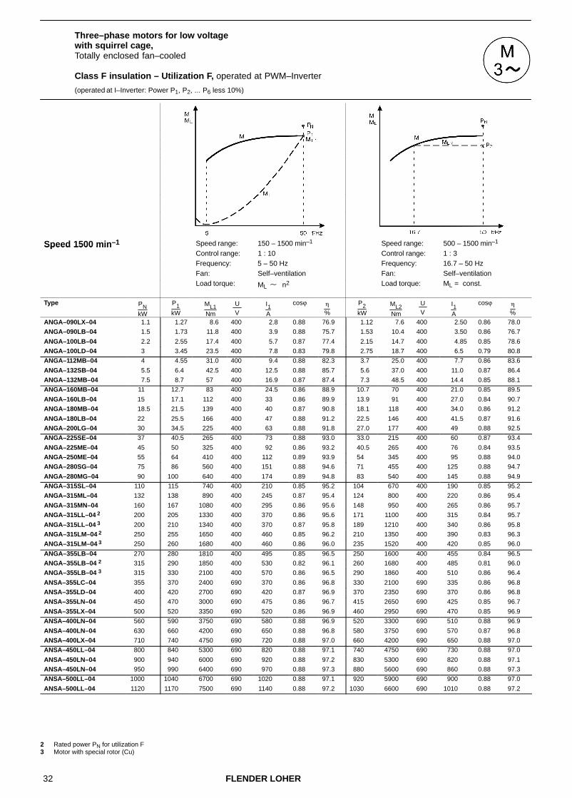
32 FLENDER LOHER
Three–phase motors for low voltage with squirrel cage,Totally enclosed fan–cooled
Class F insulation – Utilization F, operated at PWM–Inverter
(operated at I–Inverter: Power P1, P2, ... P6 less 10%)
Speed 1500 min–1 Speed range: 150 – 1500 min–1 Speed range: 500 – 1500 min–1Speed 1500 minControl range: 1 : 10 Control range: 1 : 3Frequency: 5 – 50 Hz Frequency: 16.7 – 50 HzFan: Self–ventilation Fan: Self–ventilation
Load torque: ML � n2 Load torque: ML = const.
Type PNkW
P1kW
ML1Nm
U V
I1A
cosϕ �
%
P2kW
ML2Nm
U V
I1A
cosϕ �
%
ANGA–090LX–04 1.1 1.27 8.6 400 2.8 0.88 76.9 1.12 7.6 400 2.50 0.86 78.0
ANGA–090LB–04 1.5 1.73 11.8 400 3.9 0.88 75.7 1.53 10.4 400 3.50 0.86 76.7
ANGA–100LB–04 2.2 2.55 17.4 400 5.7 0.87 77.4 2.15 14.7 400 4.85 0.85 78.6
ANGA–100LD–04 3 3.45 23.5 400 7.8 0.83 79.8 2.75 18.7 400 6.5 0.79 80.8
ANGA–112MB–04 4 4.55 31.0 400 9.4 0.88 82.3 3.7 25.0 400 7.7 0.86 83.6
ANGA–132SB–04 5.5 6.4 42.5 400 12.5 0.88 85.7 5.6 37.0 400 11.0 0.87 86.4
ANGA–132MB–04 7.5 8.7 57 400 16.9 0.87 87.4 7.3 48.5 400 14.4 0.85 88.1
ANGA–160MB–04 11 12.7 83 400 24.5 0.86 88.9 10.7 70 400 21.0 0.85 89.5
ANGA–160LB–04 15 17.1 112 400 33 0.86 89.9 13.9 91 400 27.0 0.84 90.7
ANGA–180MB–04 18.5 21.5 139 400 40 0.87 90.8 18.1 118 400 34.0 0.86 91.2
ANGA–180LB–04 22 25.5 166 400 47 0.88 91.2 22.5 146 400 41.5 0.87 91.6
ANGA–200LG–04 30 34.5 225 400 63 0.88 91.8 27.0 177 400 49 0.88 92.5
ANGA–225SE–04 37 40.5 265 400 73 0.88 93.0 33.0 215 400 60 0.87 93.4
ANGA–225ME–04 45 50 325 400 92 0.86 93.2 40.5 265 400 76 0.84 93.5
ANGA–250ME–04 55 64 410 400 112 0.89 93.9 54 345 400 95 0.88 94.0
ANGA–280SG–04 75 86 560 400 151 0.88 94.6 71 455 400 125 0.88 94.7
ANGA–280MG–04 90 100 640 400 174 0.89 94.8 83 540 400 145 0.88 94.9
ANGA–315SL–04 110 115 740 400 210 0.85 95.2 104 670 400 190 0.85 95.2
ANGA–315ML–04 132 138 890 400 245 0.87 95.4 124 800 400 220 0.86 95.4
ANGA–315MN–04 160 167 1080 400 295 0.86 95.6 148 950 400 265 0.86 95.7
ANGA–315LL–04 2 200 205 1330 400 370 0.86 95.6 171 1100 400 315 0.84 95.7
ANGA–315LL–04 3 200 210 1340 400 370 0.87 95.8 189 1210 400 340 0.86 95.8
ANGA–315LM–04 2 250 255 1650 400 460 0.85 96.2 210 1350 400 390 0.83 96.3
ANGA–315LM–04 3 250 260 1680 400 460 0.86 96.0 235 1520 400 420 0.85 96.0
ANGA–355LB–04 270 280 1810 400 495 0.85 96.5 250 1600 400 455 0.84 96.5
ANGA–355LB–04 2 315 290 1850 400 530 0.82 96.1 260 1680 400 485 0.81 96.0
ANGA–355LB–04 3 315 330 2100 400 570 0.86 96.5 290 1860 400 510 0.86 96.4
ANSA–355LC–04 355 370 2400 690 370 0.86 96.8 330 2100 690 335 0.86 96.8
ANSA–355LD–04 400 420 2700 690 420 0.87 96.9 370 2350 690 370 0.86 96.8
ANSA–355LN–04 450 470 3000 690 475 0.86 96.7 415 2650 690 425 0.85 96.7
ANSA–355LX–04 500 520 3350 690 520 0.86 96.9 460 2950 690 470 0.85 96.9
ANSA–400LN–04 560 590 3750 690 580 0.88 96.9 520 3300 690 510 0.88 96.9
ANSA–400LN–04 630 660 4200 690 650 0.88 96.8 580 3750 690 570 0.87 96.8
ANSA–400LX–04 710 740 4750 690 720 0.88 97.0 660 4200 690 650 0.88 97.0
ANSA–450LL–04 800 840 5300 690 820 0.88 97.1 740 4750 690 730 0.88 97.0
ANSA–450LN–04 900 940 6000 690 920 0.88 97.2 830 5300 690 820 0.88 97.1
ANSA–450LN–04 950 990 6400 690 970 0.88 97.3 880 5600 690 860 0.88 97.3
ANSA–500LL–04 1000 1040 6700 690 1020 0.88 97.1 920 5900 690 900 0.88 97.0
ANSA–500LL–04 1120 1170 7500 690 1140 0.88 97.2 1030 6600 690 1010 0.88 97.2
2 Rated power PN for utilization F3 Motor with special rotor (Cu)
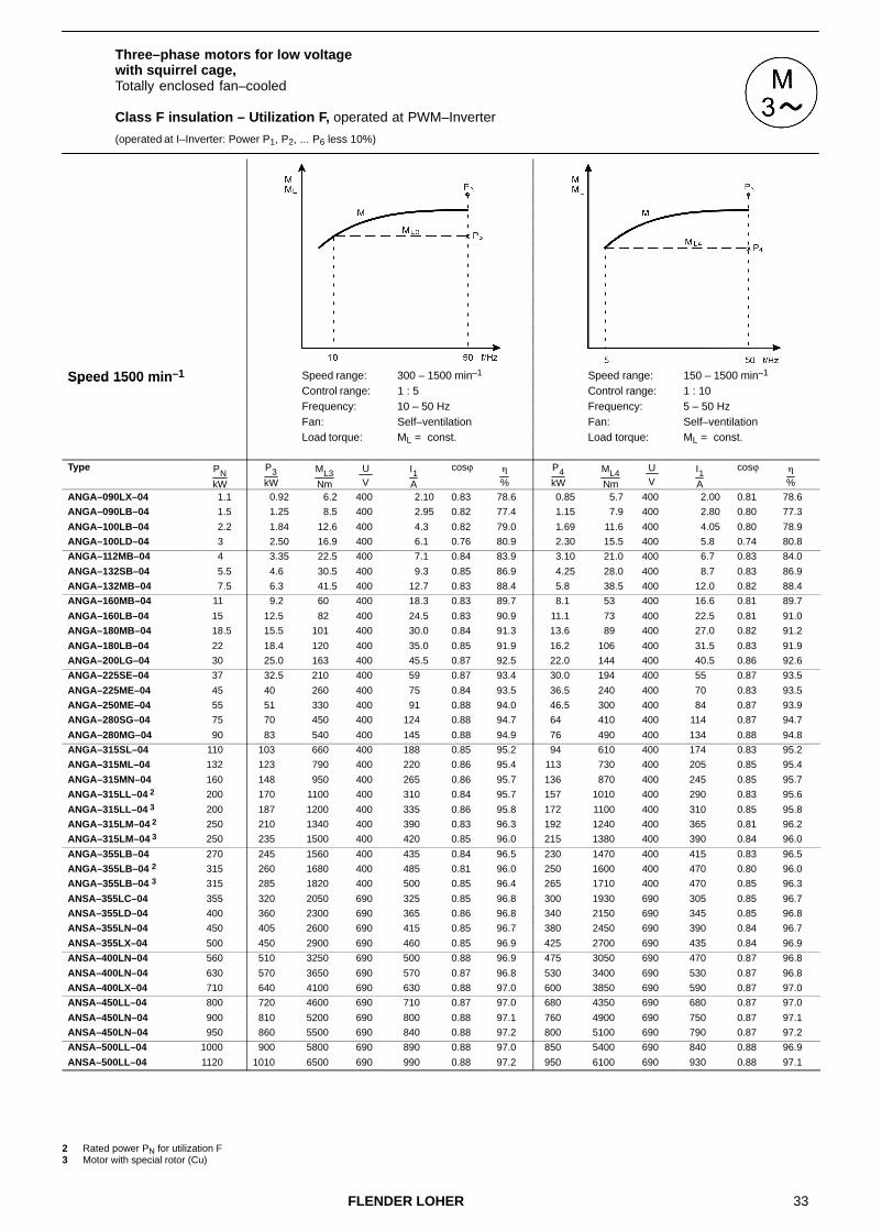
33FLENDER LOHER
Three–phase motors for low voltage with squirrel cage,Totally enclosed fan–cooled
Class F insulation – Utilization F, operated at PWM–Inverter
(operated at I–Inverter: Power P1, P2, ... P6 less 10%)
Speed 1500 min–1 Speed range: 300 – 1500 min–1 Speed range: 150 – 1500 min–1Speed 1500 minControl range: 1 : 5 Control range: 1 : 10Frequency: 10 – 50 Hz Frequency: 5 – 50 HzFan: Self–ventilation Fan: Self–ventilation
Load torque: ML = const. Load torque: ML = const.
Type PNkW
P3kW
ML3Nm
U V
I1A
cosϕ �
%
P4kW
ML4Nm
U V
I1A
cosϕ �
%
ANGA–090LX–04 1.1 0.92 6.2 400 2.10 0.83 78.6 0.85 5.7 400 2.00 0.81 78.6
ANGA–090LB–04 1.5 1.25 8.5 400 2.95 0.82 77.4 1.15 7.9 400 2.80 0.80 77.3
ANGA–100LB–04 2.2 1.84 12.6 400 4.3 0.82 79.0 1.69 11.6 400 4.05 0.80 78.9
ANGA–100LD–04 3 2.50 16.9 400 6.1 0.76 80.9 2.30 15.5 400 5.8 0.74 80.8
ANGA–112MB–04 4 3.35 22.5 400 7.1 0.84 83.9 3.10 21.0 400 6.7 0.83 84.0
ANGA–132SB–04 5.5 4.6 30.5 400 9.3 0.85 86.9 4.25 28.0 400 8.7 0.83 86.9
ANGA–132MB–04 7.5 6.3 41.5 400 12.7 0.83 88.4 5.8 38.5 400 12.0 0.82 88.4
ANGA–160MB–04 11 9.2 60 400 18.3 0.83 89.7 8.1 53 400 16.6 0.81 89.7
ANGA–160LB–04 15 12.5 82 400 24.5 0.83 90.9 11.1 73 400 22.5 0.81 91.0
ANGA–180MB–04 18.5 15.5 101 400 30.0 0.84 91.3 13.6 89 400 27.0 0.82 91.2
ANGA–180LB–04 22 18.4 120 400 35.0 0.85 91.9 16.2 106 400 31.5 0.83 91.9
ANGA–200LG–04 30 25.0 163 400 45.5 0.87 92.5 22.0 144 400 40.5 0.86 92.6
ANGA–225SE–04 37 32.5 210 400 59 0.87 93.4 30.0 194 400 55 0.87 93.5
ANGA–225ME–04 45 40 260 400 75 0.84 93.5 36.5 240 400 70 0.83 93.5
ANGA–250ME–04 55 51 330 400 91 0.88 94.0 46.5 300 400 84 0.87 93.9
ANGA–280SG–04 75 70 450 400 124 0.88 94.7 64 410 400 114 0.87 94.7
ANGA–280MG–04 90 83 540 400 145 0.88 94.9 76 490 400 134 0.88 94.8
ANGA–315SL–04 110 103 660 400 188 0.85 95.2 94 610 400 174 0.83 95.2
ANGA–315ML–04 132 123 790 400 220 0.86 95.4 113 730 400 205 0.85 95.4
ANGA–315MN–04 160 148 950 400 265 0.86 95.7 136 870 400 245 0.85 95.7
ANGA–315LL–04 2 200 170 1100 400 310 0.84 95.7 157 1010 400 290 0.83 95.6
ANGA–315LL–04 3 200 187 1200 400 335 0.86 95.8 172 1100 400 310 0.85 95.8
ANGA–315LM–04 2 250 210 1340 400 390 0.83 96.3 192 1240 400 365 0.81 96.2
ANGA–315LM–04 3 250 235 1500 400 420 0.85 96.0 215 1380 400 390 0.84 96.0
ANGA–355LB–04 270 245 1560 400 435 0.84 96.5 230 1470 400 415 0.83 96.5
ANGA–355LB–04 2 315 260 1680 400 485 0.81 96.0 250 1600 400 470 0.80 96.0
ANGA–355LB–04 3 315 285 1820 400 500 0.85 96.4 265 1710 400 470 0.85 96.3
ANSA–355LC–04 355 320 2050 690 325 0.85 96.8 300 1930 690 305 0.85 96.7
ANSA–355LD–04 400 360 2300 690 365 0.86 96.8 340 2150 690 345 0.85 96.8
ANSA–355LN–04 450 405 2600 690 415 0.85 96.7 380 2450 690 390 0.84 96.7
ANSA–355LX–04 500 450 2900 690 460 0.85 96.9 425 2700 690 435 0.84 96.9
ANSA–400LN–04 560 510 3250 690 500 0.88 96.9 475 3050 690 470 0.87 96.8
ANSA–400LN–04 630 570 3650 690 570 0.87 96.8 530 3400 690 530 0.87 96.8
ANSA–400LX–04 710 640 4100 690 630 0.88 97.0 600 3850 690 590 0.87 97.0
ANSA–450LL–04 800 720 4600 690 710 0.87 97.0 680 4350 690 680 0.87 97.0
ANSA–450LN–04 900 810 5200 690 800 0.88 97.1 760 4900 690 750 0.87 97.1
ANSA–450LN–04 950 860 5500 690 840 0.88 97.2 800 5100 690 790 0.87 97.2
ANSA–500LL–04 1000 900 5800 690 890 0.88 97.0 850 5400 690 840 0.88 96.9
ANSA–500LL–04 1120 1010 6500 690 990 0.88 97.2 950 6100 690 930 0.88 97.1
2 Rated power PN for utilization F3 Motor with special rotor (Cu)

34 FLENDER LOHER
Three–phase motors for low voltage with squirrel cage,Totally enclosed fan–cooled
Class F insulation – Utilization F, operated at PWM–Inverter
(operated at I–Inverter: Power P1, P2, ... P6 less 10%)
Speed 1500 min–1 Speed range: 150 – 1500 min–1Speed 1500 minControl range: 1 : 10Frequency: 5 – 50 HzFan: Forced ventilation
Load torque: ML = const.
Type PNkW
P5kW
ML5Nm
U V
I1A
cosϕ �
%
ANLA–090LX–04 1.1 1.27 8.6 400 2.8 0.88 76.9
ANLA–090LB–04 1.5 1.73 11.8 400 3.9 0.88 75.7
ANLA–100LB–04 2.2 2.55 17.4 400 5.7 0.87 77.4
ANLA–100LD–04 3 3.45 23.5 400 7.8 0.83 79.8
ANLA–112MB–04 4 4.6 31.0 400 9.5 0.88 82.2
ANLA–132SB–04 5.5 6.4 42.5 400 12.5 0.88 85.7
ANLA–132MB–04 7.5 8.6 57 400 16.7 0.87 87.4
ANLA–160MB–04 11 12.7 83 400 24.5 0.86 88.9
ANLA–160LB–04 15 17.1 112 400 33 0.86 89.9
ANLA–180MB–04 18.5 21.5 139 400 40 0.87 90.8
ANLA–180LB–04 22 25.5 166 400 47 0.88 91.2
ANLA–200LG–04 30 34.5 225 400 63 0.88 91.8
ANLA–225SE–04 37 41 265 400 74 0.88 92.9
ANLA–225ME–04 45 50 325 400 92 0.86 93.2
ANLA–250ME–04 55 64 410 400 112 0.89 93.9
ANLA–280SG–04 75 87 560 400 153 0.88 94.5
ANLA–280MG–04 90 99 640 400 172 0.89 94.8
ANLA–315SL–04 110 115 740 400 210 0.85 95.2
ANLA–315ML–04 132 138 890 400 245 0.87 95.4
ANLA–315MN–04 160 167 1080 400 295 0.86 95.6
ANLA–315LL–04 2 200 205 1330 400 370 0.86 95.6
ANLA–315LL–04 3 200 210 1340 400 370 0.87 95.8
ANLA–315LM–04 2 250 255 1650 400 460 0.85 96.2
ANLA–315LM–04 3 250 260 1680 400 460 0.86 96.0
ANLA–355LB–04 270 280 1810 400 495 0.85 96.5
ANLA–355LB–04 3 315 290 1850 400 530 0.82 96.1
ANLA–355LB–04 3 315 330 2100 400 570 0.86 96.5
ANUA–355LC–04 355 370 2400 690 370 0.86 96.8
ANUA–355LD–04 400 420 2700 690 420 0.87 96.9
ANUA–355LN–04 450 455 2900 690 460 0.85 96.7
ANUA–355LX–04 500 510 3250 690 510 0.86 96.9
ANUA–400LN–04 560 570 3650 690 560 0.88 96.9
ANUA–400LN–04 630 640 4100 690 630 0.88 96.8
ANUA–400LX–04 710 720 4600 690 700 0.88 97.0
ANUA–450LL–04 800 810 5200 690 790 0.88 97.1
ANUA–450LN–04 900 910 5800 690 890 0.88 97.2
ANUA–450LN–04 950 960 6200 690 940 0.88 97.3
ANUA–500LL–04 1000 1010 6500 690 990 0.88 97.0
ANUA–500LL–04 1120 1130 7300 690 1100 0.88 97.2
2 Rated power PN for utilization F3 Motor with special rotor (Cu)

35FLENDER LOHER
Three–phase motors for low voltage with squirrel cage,Totally enclosed fan–cooled
Class F insulation – Utilization F, operated at PWM–Inverter
(operated at I–Inverter: Power P1, P2, ... P6 less 10%)
Speed 1500 min–1 Speed range: 1500 – 2600 min–1Speed 1500 minControl range: 10 : 17Frequency: 50 – 87 HzFan: Self–ventilation,
Forced ventilationLoad torque: ML = const./ ML � n2
Type PNkW
P6kW
ML6Nm
U V
I1A
cosϕ �
%
ANGA–090LX–04 1.1 1.76 6.9 400 4.0 0.83 79.9
ANGA–090LB–04 1.5 2.4 9.4 400 5.5 0.82 80.3
ANGA–100LB–04 2.2 3.5 13.9 400 7.9 0.82 81.6
ANGA–100LD–04 3 4.8 18.8 400 11.2 0.77 83.7
ANGA–112MB–04 4 6.4 25 400 13.3 0.85 84.8
ANGA–132SB–04 5.5 8.8 34 400 17.5 0.85 87.4
ANGA–132MB–04 7.5 12.0 46 400 23.5 0.84 89.6
ANGA–160MB–04 11 17.2 65 400 34.0 0.84 89.2
ANGA–160LB–04 15 23.5 89 400 45.5 0.83 92.0
ANGA–180MB–04 18.5 29.0 109 400 55 0.85 90.9
ANGA–180LB–04 22 34.5 130 400 65 0.85 91.7
ANGA–200LG–04 30 47 176 400 86 0.88 92.1
ANGA–225SE–04 37 54 205 400 99 0.87 92.8
ANGA–225ME–04 45 66 245 400 127 0.83 92.9
ANGA–250ME–04 55 81 300 400 147 0.87 93.0
ANGA–280SG–04 75 110 410 400 198 0.87 93.6
ANGA–280MG–04 90 126 470 400 225 0.87 93.7
ANGA–315SL–04 110 151 560 400 290 0.83 93.7
ANGA–315ML–04 132 181 670 400 335 0.85 94.3
ANGA–315MN–04 160 220 820 400 405 0.84 94.9
ANGA–315LL–04 2 200 255 950 400 485 0.82 94.4
ANGA–315LL–04 3 200 275 1020 400 510 0.84 94.5
ANGA–315LM–04 2 250 315 1180 400 610 0.80 95.7
ANGA–315LM–04 3 250 345 1270 400 640 0.83 95.1
2 Rated power PN for utilization F3 Motor with special rotor (Cu)
For mains operation the motor windings have to be Y–connected.
For inverter operation ∆–connection of the windings is required.
For the control range below 50 Hz the limit torques ML2, ML3, ML4 have to be observed (see Chapter 2.4.2.2)

36 FLENDER LOHER
Three–phase motors for low voltage with squirrel cage,Totally enclosed fan–cooled
Class F insulation – Utilization F, operated at PWM–Inverter
(operated at I–Inverter: Power P1, P2, ... P6 less 10%)
Speed 1000 min–1 Speed range: 100 – 1000 min–1 Speed range: 330 – 1000 min–1Speed 1000 minControl range: 1 : 10 Control range: 1 : 3Frequency: 5 – 50 Hz Frequency: 16.7 – 50 HzFan: Self–ventilation Fan: Self–ventilation
Load torque: ML � n2 Load torque: ML = const.
Type PNkW
P1kW
ML1Nm
U V
I1A
cosϕ �
%
P2kW
ML2Nm
U V
I1A
cosϕ �
%
ANGA–090LX–06 0.75 0.87 9.2 400 2.35 0.82 69.6 0.70 7.4 400 1.95 0.76 72.4
ANGA–090LB–06 1.1 1.27 13.3 400 3.65 0.77 69.6 0.95 9.9 400 3.05 0.68 71.3
ANGA–100LB–06 1.5 1.73 17.6 400 4.7 0.76 73.9 1.55 15.8 400 4.35 0.74 74.2
ANGA–112MB–06 2.2 2.55 26.0 400 6.1 0.82 77.0 2.15 22.0 400 5.2 0.80 78.2
ANGA–132SB–06 3. 3.45 34.5 400 7.3 0.84 84.1 3.20 32.0 400 6.8 0.83 84.5
ANGA–132MB–06 4 4.6 46 400 9.9 0.83 83.0 4.25 42.5 400 9.3 0.82 83.4
ANGA–132MD–06 5.5 6.4 64 400 13.4 0.84 84.6 5.9 59 400 12.5 0.83 85.0
ANGA–160MB–06 7.5 8.7 85 400 17.4 0.86 86.8 8.0 79 400 16.1 0.85 87.1
ANGA–160LB–06 11 12.7 124 400 25.0 0.84 88.6 11.7 115 400 23.5 0.83 88.8
ANGA–180LB–06 15 17.3 171 400 34.5 0.83 89.3 15.5 153 400 31.5 0.82 89.8
ANGA–200LG–06 18.5 21.5 210 400 42.5 0.84 88.8 18.8 186 400 36.5 0.85 89.7
ANGA–200LJ–06 22 25.5 250 400 51 0.83 89.6 19.9 197 400 40 0.81 90.5
ANGA–225ME–06 30 34.5 340 400 66 0.84 91.6 29.0 285 400 56 0.83 92.0
ANGA–250ME–06 37 42.5 415 400 83 0.83 92.0 38.5 375 400 76 0.82 92.1
ANGA–280SG–06 45 51 500 400 91 0.88 93.1 42.5 410 400 77 0.87 93.4
ANGA–280MG–06 55 62 600 400 112 0.88 92.9 51 495 400 93 0.86 93.0
ANGA–315SL–06 75 78 760 400 143 0.85 94.3 71 690 400 131 0.85 94.3
ANGA–315ML–06 90 94 910 400 166 0.87 95.2 85 820 400 151 0.87 95.3
ANGA–315MM–06 110 115 1110 400 205 0.87 95.0 104 1000 400 185 0.87 95.1
ANGA–315MN–06 2 132 138 1330 400 240 0.89 95.3 117 1130 400 205 0.88 95.5
ANGA–315LL–06 160 167 1610 400 290 0.88 95.5 150 1450 400 260 0.88 95.6
ANGA–315LM–06 2 200 210 2000 400 375 0.86 95.8 176 1700 400 320 0.84 95.9
ANGA–315LM–06 3 200 210 2000 400 365 0.88 95.9 188 1810 400 325 0.88 95.9
ANGA–355LB–06 3 250 260 2500 400 460 0.85 96.3 230 2200 400 415 0.84 96.3
ANSA–355LC–06 280 295 2800 690 300 0.86 96.3 260 2500 690 265 0.85 96.3
ANSA–355LD–06 315 330 3150 690 340 0.85 96.4 290 2800 690 300 0.83 96.4
ANSA–355LN–06 355 370 3550 690 375 0.86 96.4 330 3150 690 335 0.85 96.4
ANSA–355LN–06 400 420 4000 690 435 0.84 96.4 370 3550 690 385 0.83 96.5
ANSA–400LN–06 450 470 4500 690 485 0.84 96.6 415 4000 690 430 0.83 96.6
ANSA–400LN–06 500 520 5000 690 530 0.84 96.7 460 4450 690 475 0.84 96.7
ANSA–450LL–06 560 590 5600 690 600 0.85 96.9 520 4950 690 530 0.85 96.9
ANSA–450LL–06 630 660 6300 690 670 0.85 97.0 580 5600 690 590 0.85 96.9
ANSA–450LN–06 710 740 7100 690 750 0.85 97.0 660 6300 690 670 0.85 97.0
ANSA–450LN–06 800 840 8000 690 850 0.85 97.1 740 7100 690 760 0.84 97.1
ANSA–500LL–06 900 940 9000 690 960 0.85 97.0 830 8000 690 850 0.85 97.0
ANSA–500LN–06 1000 1040 10000 690 1050 0.85 97.1 920 8900 690 940 0.85 97.0
ANSA–500LN–06 1120 1170 11200 690 1170 0.86 97.2 1030 9900 690 1030 0.86 97.2
ANSA–560LL–06 1250 1310 12500 690 1290 0.88 97.2 1160 11100 690 1140 0.88 97.2
ANSA–560LL–06 1400 1460 14000 690 1460 0.86 97.2 1290 12400 690 1300 0.86 97.2
ANSA–560LN–06 1600 1670 16000 690 1640 0.88 97.4 1480 14200 690 1450 0.88 97.4
2 Rated power PN for utilization F3 Motor with special rotor (Cu)

37FLENDER LOHER
Three–phase motors for low voltage with squirrel cage,Totally enclosed fan–cooled
Class F insulation – Utilization F, operated at PWM–Inverter
(operated at I–Inverter: Power P1, P2, ... P6 less 10%)
Speed 1000 min–1 Speed range: 200 – 1000 min–1 Speed range: 100 – 1000 min–1Speed 1000 minControl range: 1 : 5 Control range: 1 : 10Frequency: 10 – 50 Hz Frequency: 5 – 50 HzFan: Self–ventilation Fan: Self–ventilation
Load torque: ML = const. Load torque: ML = const.
Type PNkW
P3kW
ML3Nm
U V
I1A
cosϕ �
%
P4kW
ML4Nm
U V
I1A
cosϕ �
%
ANGA–090LX–06 0.75 0.62 6.6 400 1.81 0.72 73.0 0.55 5.9 400 1.70 0.69 73.0
ANGA–090LB–06 1.1 0.84 8.7 400 2.70 0.67 72.8 0.75 7.8 400 2.60 0.63 72.3
ANGA–100LB–06 1.5 1.25 12.7 400 3.9 0.68 73.7 1.15 11.7 400 3.75 0.65 73.2
ANGA–112MB–06 2.2 1.84 18.7 400 4.6 0.77 78.6 1.69 17.2 400 4.35 0.75 78.5
ANGA–132SB–06 3. 2.50 25.0 400 5.6 0.78 84.9 2.30 23.0 400 5.3 0.77 84.8
ANGA–132MB–06 4 3.35 33.5 400 7.8 0.78 83.9 3.10 31.0 400 7.4 0.76 83.8
ANGA–132MD–06 5.5 4.6 46 400 10.3 0.78 85.6 4.25 42.5 400 9.8 0.77 85.5
ANGA–160MB–06 7.5 6.3 62 400 13.4 0.80 87.4 5.5 54 400 12.2 0.77 87.2
ANGA–160LB–06 11 9.2 90 400 19.5 0.79 89.1 8.1 79 400 18 0.76 89.0
ANGA–180LB–06 15 12.5 124 400 26.5 0.79 90.2 11.1 109 400 24 0.76 90.2
ANGA–200LG–06 18.5 15.5 153 400 30.5 0.84 90.3 13.6 135 400 27 0.82 90.5
ANGA–200LJ–06 22 18.4 182 400 37.5 0.80 90.6 16.2 160 400 34 0.79 90.7
ANGA–225ME–06 30 28.0 275 400 55 0.83 92.1 25.5 250 400 50 0.81 92.1
ANGA–250ME–06 37 34.5 335 400 69 0.81 92.1 31.5 305 400 64 0.80 91.9
ANGA–280SG–06 45 42 405 400 76 0.87 93.4 38.0 370 400 69 0.86 93.4
ANGA–280MG–06 55 51 490 400 93 0.86 93.0 46.5 450 400 86 0.85 93.0
ANGA–315SL–06 75 70 680 400 129 0.84 94.3 64 620 400 120 0.84 94.3
ANGA–315ML–06 90 84 810 400 150 0.86 95.3 77 750 400 138 0.86 95.3
ANGA–315MM–06 110 103 990 400 183 0.87 95.1 94 910 400 169 0.86 95.1
ANGA–315MN–06 2 132 116 1120 400 200 0.88 95.5 107 1030 400 187 0.88 95.5
ANGA–315LL–06 160 149 1430 400 260 0.88 95.6 136 1320 400 240 0.87 95.6
ANGA–315LM–06 2 200 176 1700 400 320 0.84 95.9 162 1560 400 300 0.83 95.9
ANGA–315LM–06 3 200 186 1800 400 325 0.88 95.9 172 1650 400 300 0.87 95.9
ANGA–355LB–06 3 250 225 2150 400 405 0.83 96.3 210 2050 400 385 0.82 96.2
ANSA–355LC–06 280 255 2450 690 265 0.85 96.3 235 2300 690 245 0.84 96.3
ANSA–355LD–06 315 285 2750 690 300 0.83 96.4 265 2550 690 280 0.82 96.3
ANSA–355LN–06 355 320 3100 690 325 0.85 96.4 300 2900 690 310 0.84 96.4
ANSA–355LN–06 400 360 3450 690 375 0.83 96.5 340 3250 690 360 0.82 96.5
ANSA–400LN–06 450 405 3900 690 425 0.83 96.6 380 3650 690 400 0.83 96.6
ANSA–400LN–06 500 450 4350 690 470 0.83 96.7 425 4050 690 445 0.83 96.7
ANSA–450LL–06 560 510 4850 690 520 0.84 96.9 475 4550 690 490 0.84 96.8
ANSA–450LL–06 630 570 5500 690 580 0.84 96.9 530 5100 690 550 0.84 96.9
ANSA–450LN–06 710 640 6200 690 650 0.85 97.0 600 5800 690 620 0.84 97.0
ANSA–450LN–06 800 720 6900 690 740 0.84 97.1 680 6500 690 700 0.83 97.1
ANSA–500LL–06 900 810 7800 690 830 0.85 97.0 760 7300 690 780 0.84 96.9
ANSA–500LN–06 1000 900 8700 690 920 0.85 97.0 850 8100 690 870 0.84 97.0
ANSA–500LN–06 1120 1010 9700 690 1010 0.86 97.2 950 9100 690 950 0.86 97.1
ANSA–560LL–06 1250 1130 10800 690 1110 0.87 97.2 1060 10200 690 1050 0.87 97.2
ANSA–560LL–06 1400 1260 12100 690 1270 0.86 97.2 1190 11400 690 1210 0.85 97.1
ANSA–560LN–06 1600 1440 13800 690 1420 0.88 97.3 1360 13000 690 1340 0.87 97.3
2 Rated power PN for utilization F3 Motor with special rotor (Cu)

38 FLENDER LOHER
Three–phase motors for low voltage with squirrel cage,Totally enclosed fan–cooled
Class F insulation – Utilization F, operated at PWM–Inverter
(operated at I–Inverter: Power P1, P2, ... P6 less 10%)
Speed 1000 min–1 Speed range: 100 – 1000 min–1Speed 1000 minControl range: 1 : 10Frequency: 5 – 50 HzFan: Forced ventilation
Load torque: ML = const.
Type PNkW
P5kW
ML5Nm
U V
I1A
cosϕ �
%
ANLA–090LX–06 0.75 .87 9.2 400 2.35 0.82 69.6
ANLA–090LB–06 1.1 1.27 13.3 400 3.65 0.77 69.6
ANLA–100LB–06 1.5 1.73 17.6 400 4.70 0.76 73.9
ANLA–112MB–06 2.2 2.55 26.0 400 6.1 0.82 77.0
ANLA–132SB–06 3. 3.45 34.5 400 7.3 0.84 84.1
ANLA–132MB–06 4 4.6 46 400 9.9 0.83 83.0
ANLA–132MD–06 5.5 6.4 64 400 13.4 0.84 84.6
ANLA–160MB–06 7.5 8.6 85 400 17.2 0.86 86.9
ANLA–160LB–06 11 12.7 124 400 25.0 0.84 88.6
ANLA–180LB–06 15 17.3 171 400 34.5 0.83 89.3
ANLA–200LG–06 18.5 21.0 210 400 41.5 0.85 89.0
ANLA–200LJ–06 22 25.5 250 400 51 0.83 89.6
ANLA–225ME–06 30 34.5 340 400 66 0.84 91.6
ANLA–250ME–06 37 42.5 415 400 83 0.83 92.0
ANLA–280SG–06 45 52 500 400 93 0.88 93.0
ANLA–280MG–06 55 62 600 400 112 0.88 92.9
ANLA–315SL–06 75 78 760 400 143 0.85 94.3
ANLA–315ML–06 90 94 910 400 166 0.87 95.2
ANLA–315MM–06 110 115 1110 400 205 0.87 95.0
ANLA–315MN–06 2 132 138 1330 400 240 0.89 95.3
ANLA–315LL–06 160 167 1610 400 290 0.88 95.5
ANLA–315LM–06 2 200 205 2000 400 370 0.85 95.8
ANLA–315LM–06 3 200 210 2000 400 365 0.88 95.9
ANLA–355LB–06 3 250 260 2500 400 460 0.85 96.3
ANUA–355LC–06 280 290 2800 690 295 0.85 96.3
ANUA–355LD–06 315 330 3150 690 340 0.85 96.4
ANUA–355LN–06 355 360 3450 690 365 0.86 96.4
ANUA–355LN–06 400 405 3900 690 420 0.84 96.4
ANUA–400LN–06 450 455 4400 690 470 0.84 96.6
ANUA–400LN–06 500 510 4850 690 520 0.84 96.7
ANUA–450LL–06 560 570 5400 690 580 0.85 96.9
ANUA–450LL–06 630 640 6100 690 650 0.85 97.0
ANUA–450LN–06 710 720 6900 690 730 0.85 97.0
ANUA–450LN–06 800 810 7800 690 820 0.85 97.1
ANUA–500LL–06 900 910 8700 690 920 0.85 97.0
ANUA–500LN–06 1000 1010 9700 690 1020 0.85 97.1
ANUA–500LN–06 1120 1130 10900 690 1130 0.86 97.2
ANUA–560LL–06 1250 1270 12100 690 1250 0.88 97.2
ANUA–560LL–06 1400 1420 13600 690 1420 0.86 97.2
ANUA–560LN–06 1600 1620 15500 690 1590 0.88 97.4
2 Rated power PN for utilization F3 Motor with special rotor (Cu)

39FLENDER LOHER
Three–phase motors for low voltage with squirrel cage,Totally enclosed fan–cooled
Class F insulation – Utilization F, operated at PWM–Inverter
(operated at I–Inverter: Power P1, P2, ... P6 less 10%)
Speed 1000 min–1 Speed range: 1000 – 1730 min–1Speed 1000 minControl range: 10 : 17Frequency: 50 – 87 HzFan: Self–ventilation,
Forced ventilationLoad torque: ML = const./ ML � n2
Type PNkW
P6kW
ML6Nm
U V
I1A
cosϕ �
%
ANGA–090LX–06 0.75 1.20 7.4 400 3.3 0.71 78.0
ANGA–090LB–06 1.1 1.76 10.6 400 5.4 0.65 77.5
ANGA–100LB–06 1.5 2.4 14.1 400 7.1 0.67 77.8
ANGA–112MB–06 2.2 3.5 20.5 400 8.6 0.77 79.6
ANGA–132SB–06 3. 4.8 27.5 400 10.6 0.80 85.4
ANGA–132MB–06 4 6.4 37 400 14.3 0.78 85.9
ANGA–132MD–06 5.5 8.8 51 400 19.1 0.79 87.2
ANGA–160MB–06 7.5 11.7 67 400 24.5 0.81 88.2
ANGA–160LB–06 11 17.2 97 400 36 0.80 89.8
ANGA–180LB–06 15 23.5 134 400 48 0.79 91.5
ANGA–200LG–06 18.5 29.0 166 400 56 0.84 90.8
ANGA–200LJ–06 22 34.5 196 400 69 0.81 91.3
ANGA–225ME–06 30 44 250 400 88 0.81 91.8
ANGA–250ME–06 37 54 305 400 112 0.80 90.2
ANGA–280SG–06 45 66 370 400 121 0.86 93.3
ANGA–280MG–06 55 78 440 400 147 0.85 92.0
ANGA–315SL–06 75 103 570 400 198 0.83 93.2
ANGA–315ML–06 90 123 690 400 225 0.85 94.9
ANGA–315MM–06 110 151 840 400 275 0.85 94.7
ANGA–315MN–06 2 132 181 1010 400 320 0.87 95.4
ANGA–315LL–06 160 220 1220 400 390 0.87 95.5
ANGA–315LM–06 2 200 260 1450 400 490 0.82 95.6
ANGA–315LM–06 3 200 275 1520 400 490 0.87 95.4
2 Rated power PN for utilization F3 Motor with special rotor (Cu)
For mains operation the motor windings have to be Y–connected.
For inverter operation ∆–connection of the windings is required.
For the control range below 50 Hz the limit torques ML2, ML3, ML4 have to be observed (see Chapter 2.4.2.2)

40 FLENDER LOHER
Three–phase motors for low voltage with squirrel cage,Totally enclosed fan–cooled
Class F insulation – Utilization F, operated at PWM–Inverter
(operated at I–Inverter: Power P1, P2, ... P6 less 10%)
Speed 750 min–1 Speed range: 75 – 750 min–1 Speed range: 250 – 750 min–1Speed 750 minControl range: 1 : 10 Control range: 1 : 3Frequency: 5 – 50 Hz Frequency: 16.7 – 50 HzFan: Self–ventilation Fan: Self–ventilation
Load torque: ML � n2 Load torque: ML = const.
Type PNkW
P1kW
ML1Nm
U V
I1A
cosϕ �
%
P2kW
ML2Nm
U V
I1A
cosϕ �
%
ANGA–090LX–08 0.37 0.43 6.0 400 1.51 0.71 62.7 0.40 5.5 400 1.44 0.69 63.1
ANGA–090LB–08 0.55 0.64 9.0 400 2.10 0.72 66.0 0.59 8.3 400 1.96 0.70 66.9
ANGA–100LB–08 0.75 0.87 11.8 400 2.55 0.74 70.2 0.80 10.9 400 2.45 0.72 70.4
ANGA–100LD–08 1.1 1.27 17.5 400 3.55 0.77 71.2 1.00 13.8 400 3.0 0.71 72.1
ANGA–112MB–08 1.5 1.73 23.5 400 4.7 0.77 73.7 1.56 21.5 400 4.3 0.74 74.5
ANGA–132SB–08 2.2 2.55 34.0 400 6.3 0.76 81.4 2.35 31.5 400 5.9 0.74 81.8
ANGA–132MB–08 3 3.45 46.5 400 8.3 0.75 83.2 3.20 43 400 7.9 0.74 83.5
ANGA–160MB–08 4 4.6 62 400 10.4 0.79 84.3 4.25 57 400 9.7 0.78 84.9
ANGA–160MD–08 5.5 6.4 84 400 14.6 0.77 85.9 5.9 77 400 13.7 0.75 86.2
ANGA–160LB–08 7.5 8.7 115 400 19.4 0.79 85.5 8.0 106 400 18.1 0.77 85.9
ANGA–180LB–08 11 12.7 169 400 26 0.83 87.6 11.7 156 400 24.0 0.82 88.1
ANGA–200LG–08 15 17.3 230 400 37 0.80 86.8 15.5 205 400 33.5 0.79 87.8
ANGA–225SE–08 18.5 21.5 285 400 45 0.81 88.4 18.8 250 400 39.5 0.80 89.1
ANGA–225ME–08 22 25.5 335 400 54 0.79 89.5 23.5 310 400 50 0.78 89.8
ANGA–250ME–08 30 34.5 450 400 68 0.83 90.9 32.0 415 400 63 0.82 91.0
ANGA–280SG–08 37 42.5 550 400 83 0.82 92.0 36.0 465 400 71 0.81 92.3
ANGA–280MG–08 45 52 670 400 101 0.82 92.5 44.5 580 400 87 0.81 92.9
ANGA–315SL–08 55 57 740 400 112 0.80 94.1 52 670 400 103 0.79 94.2
ANGA–315ML–08 75 78 1010 400 152 0.81 94.0 71 910 400 139 0.80 94.1
ANGA–315MM–08 90 94 1210 400 180 0.82 94.6 85 1100 400 164 0.81 94.7
ANGA–315MN–08 2 110 115 1480 400 225 0.81 94.0 98 1260 400 195 0.79 94.2
ANGA–315LL–08 132 138 1780 400 265 0.81 94.4 120 1540 400 235 0.80 94.6
ANGA–315LM–08 2 160 155 2000 400 300 0.81 94.9 126 1630 400 250 0.78 95.2
ANGA–315LM–08 3 160 167 2150 400 315 0.82 95.5 150 1920 400 290 0.80 95.6
ANGA–355LB–08 3 200 210 2700 400 390 0.81 95.7 185 2350 400 350 0.79 95.7
ANSA–355LC–08 225 235 3000 690 250 0.82 95.4 210 2650 690 230 0.81 95.5
ANSA–355LD–08 250 260 3350 690 280 0.82 95.6 230 2950 690 250 0.80 95.6
ANSA–355LN–08 280 295 3750 690 315 0.82 95.9 260 3350 690 280 0.81 96.0
ANSA–355LX–08 315 330 4250 690 350 0.83 95.8 290 3700 690 310 0.82 95.9
ANSA–400LL–08 355 370 4750 690 395 0.82 96.1 330 4200 690 355 0.81 96.2
ANSA–400LN–08 400 420 5400 690 445 0.82 96.2 370 4750 690 395 0.81 96.2
ANSA–400LX–08 450 470 6000 690 500 0.82 96.2 415 5300 690 445 0.81 96.3
ANSA–450LL–08 500 520 6700 690 540 0.84 96.5 460 5900 690 480 0.83 96.6
ANSA–450LN–08 560 590 7500 690 610 0.84 96.6 520 6600 690 540 0.83 96.6
ANSA–450LN–08 630 660 8400 690 680 0.84 96.7 580 7500 690 610 0.83 96.7
ANSA–450LX–08 670 700 9000 690 730 0.83 96.8 620 7900 690 650 0.82 96.8
ANSA–500LL–08 710 740 9500 690 750 0.86 96.9 660 8400 690 670 0.85 96.9
ANSA–500LL–08 800 840 10700 690 850 0.86 96.9 740 9500 690 750 0.85 97.0
ANSA–500LN–08 900 940 12100 690 970 0.84 96.7 830 10700 690 860 0.84 96.7
ANSA–500LX–08 950 990 12700 690 1030 0.83 96.9 880 11200 690 920 0.83 96.9
ANSA–560LL–08 1000 1040 13400 690 1070 0.84 97.0 920 11800 690 950 0.84 97.0
ANSA–560LL–08 1100 1150 14700 690 1180 0.84 97.6 1020 13000 690 1050 0.84 97.5
ANSA–560LN–08 1200 1250 16100 690 1280 0.84 97.0 1110 14200 690 1140 0.84 97.0
ANSA–560LN–08 1350 1410 18100 690 1450 0.84 97.1 1250 16000 690 1290 0.84 97.1 2 Rated power PN for utilization F3 Motor with special rotor (Cu)

41FLENDER LOHER
Three–phase motors for low voltage with squirrel cage,Totally enclosed fan–cooled
Class F insulation – Utilization F, operated at PWM–Inverter
(operated at I–Inverter: Power P1, P2, ... P6 less 10%)
Speed 750 min–1 Speed range: 150 – 750 min–1 Speed range: 75 – 750 min–1Speed 750 minControl range: 1 : 5 Control range: 1 : 10Frequency: 10 – 50 Hz Frequency: 5 – 50 HzFan: Self–ventilation Fan: Self–ventilation
Load torque: ML = const. Load torque: ML = const.
Type PNkW
P3kW
ML3Nm
U V
I1A
cosϕ �
%
P4kW
ML4Nm
U V
I1A
cosϕ �
%
ANGA–090LX–08 0.37 0.31 4.3 400 1.29 0.62 62.4 0.28 4.0 400 1.25 0.60 61.7
ANGA–090LB–08 0.55 0.46 6.5 400 1.70 0.64 67.2 0.42 6.0 400 1.65 0.61 66.8
ANGA–100LB–08 0.75 0.63 8.6 400 2.15 0.66 69.7 0.58 7.9 400 2.1 0.63 69.1
ANGA–100LD–08 1.1 0.88 12.1 400 2.85 0.68 71.8 0.77 10.6 400 2.7 0.64 71.0
ANGA–112MB–08 1.5 1.25 17.1 400 3.75 0.69 75.0 1.15 15.8 400 3.6 0.66 74.8
ANGA–132SB–08 2.2 1.84 24.5 400 5.0 0.69 82.0 1.69 22.5 400 4.8 0.66 81.7
ANGA–132MB–08 3 2.50 33.5 400 6.7 0.68 83.8 2.30 31.0 400 6.4 0.66 83.6
ANGA–160MB–08 4 3.35 44.5 400 8.1 0.73 85.9 2.95 39.5 400 7.5 0.70 86.0
ANGA–160MD–08 5.5 4.6 61 400 11.6 0.70 86.4 4.05 53 400 10.9 0.66 86.1
ANGA–160LB–08 7.5 6.3 83 400 15.2 0.73 86.2 5.5 73 400 14.1 0.69 85.9
ANGA–180LB–08 11 9.2 122 400 20.0 0.77 88.8 8.1 108 400 18.5 0.74 88.8
ANGA–200LG–08 15 12.5 168 400 27.5 0.76 88.9 11.1 148 400 25.5 0.74 89.2
ANGA–225SE–08 18.5 17.3 230 400 36.5 0.79 89.4 15.7 205 400 34 0.77 89.6
ANGA–225ME–08 22 20.5 270 400 45 0.76 90.1 18.6 245 400 42 0.74 90.1
ANGA–250ME–08 30 28.0 365 400 56 0.81 91.2 25.5 330 400 52 0.80 91.1
ANGA–280SG–08 37 34.5 450 400 69 0.81 92.4 31.5 405 400 64 0.79 92.4
ANGA–280MG–08 45 42 540 400 83 0.81 92.9 38 495 400 77 0.79 93.0
ANGA–315SL–08 55 51 660 400 102 0.79 94.2 47 610 400 95 0.78 94.2
ANGA–315ML–08 75 70 900 400 138 0.80 94.1 64 830 400 128 0.79 94.1
ANGA–315MM–08 90 84 1080 400 163 0.81 94.7 77 1000 400 151 0.80 94.8
ANGA–315MN–08 2 110 96 1240 400 192 0.79 94.3 88 1130 400 179 0.78 94.3
ANGA–315LL–08 132 118 1520 400 230 0.80 94.6 107 1380 400 215 0.79 94.6
ANGA–315LM–08 2 160 124 1600 400 250 0.78 95.2 113 1460 400 230 0.76 95.2
ANGA–315LM–08 3 160 148 1900 400 285 0.80 95.6 134 1730 400 265 0.78 95.6
ANGA–355LB–08 3 200 180 2300 400 345 0.79 95.7 169 2150 400 330 0.78 95.7
ANSA–355LC–08 225 205 2600 690 225 0.80 95.5 191 2450 690 210 0.79 95.5
ANSA–355LD–08 250 225 2900 690 245 0.80 95.6 210 2700 690 235 0.79 95.6
ANSA–355LN–08 280 255 3250 690 275 0.81 96.0 235 3050 690 260 0.79 96.0
ANSA–355LX–08 315 285 3650 690 305 0.81 95.9 260 3400 690 285 0.80 95.9
ANSA–400LL–08 355 320 4100 690 345 0.80 96.2 300 3850 690 330 0.79 96.2
ANSA–400LN–08 400 360 4650 690 385 0.81 96.3 335 4350 690 365 0.80 96.3
ANSA–400LX–08 450 405 5200 690 440 0.81 96.3 380 4900 690 415 0.80 96.3
ANSA–450LL–08 500 450 5800 690 475 0.83 96.6 425 5400 690 450 0.82 96.6
ANSA–450LN–08 560 510 6500 690 530 0.83 96.6 475 6100 690 500 0.82 96.6
ANSA–450LN–08 630 570 7300 690 600 0.83 96.7 530 6800 690 560 0.82 96.7
ANSA–450LX–08 670 600 7700 690 640 0.82 96.8 570 7300 690 610 0.81 96.8
ANSA–500LL–08 710 640 8200 690 660 0.84 96.9 600 7700 690 620 0.84 96.9
ANSA–500LL–08 800 720 9200 690 740 0.85 96.9 680 8700 690 700 0.84 96.9
ANSA–500LN–08 900 810 10400 690 840 0.84 96.7 760 9800 690 790 0.83 96.7
ANSA–500LX–08 950 860 11000 690 900 0.82 96.9 800 10300 690 850 0.82 96.9
ANSA–560LL–08 1000 900 11500 690 930 0.84 96.9 850 10800 690 880 0.84 96.9
ANSA–560LL–08 1100 990 12700 690 1020 0.84 97.5 930 11900 690 960 0.83 97.4
ANSA–560LN–08 1200 1080 13900 690 1110 0.84 97.0 1020 13000 690 1050 0.84 96.9
ANSA–560LN–08 1350 1220 15600 690 1260 0.84 97.1 1140 14600 690 1180 0.83 97.0 2 Rated power PN for utilization F3 Motor with special rotor (Cu)
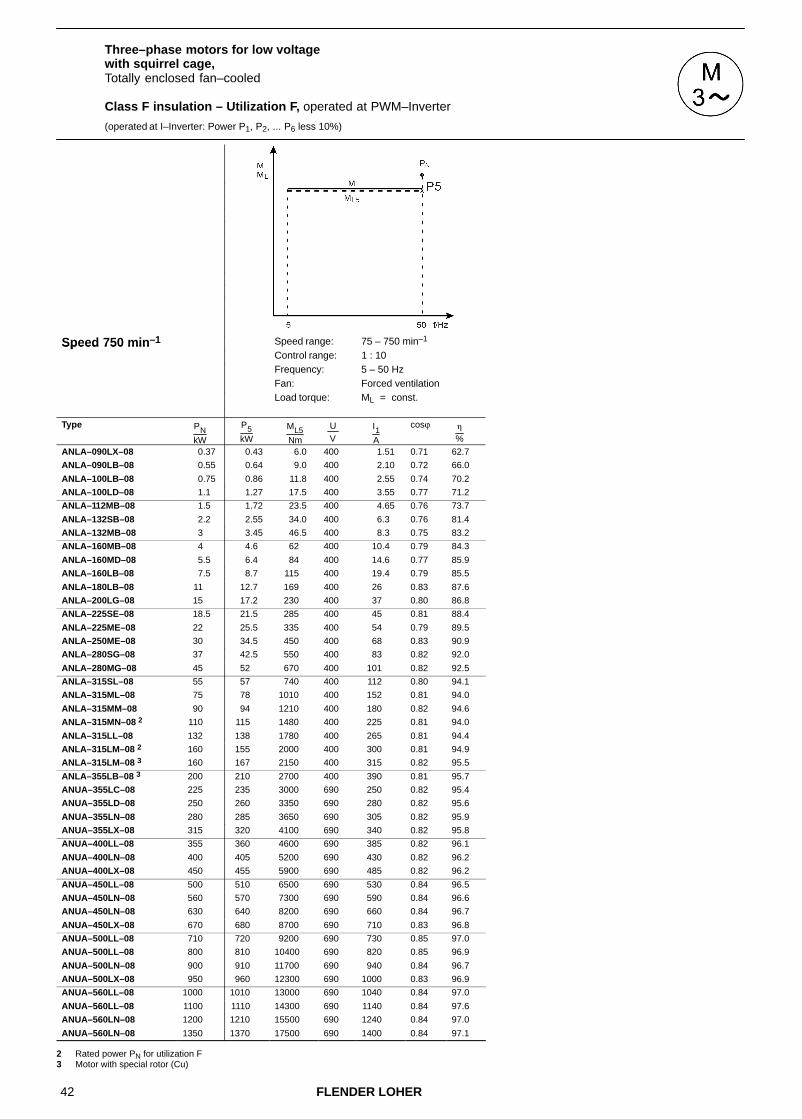
42 FLENDER LOHER
Three–phase motors for low voltage with squirrel cage,Totally enclosed fan–cooled
Class F insulation – Utilization F, operated at PWM–Inverter
(operated at I–Inverter: Power P1, P2, ... P6 less 10%)
Speed 750 min–1 Speed range: 75 – 750 min–1Speed 750 minControl range: 1 : 10Frequency: 5 – 50 HzFan: Forced ventilation
Load torque: ML = const.
Type PNkW
P5kW
ML5Nm
U V
I1A
cosϕ �
%
ANLA–090LX–08 0.37 0.43 6.0 400 1.51 0.71 62.7
ANLA–090LB–08 0.55 0.64 9.0 400 2.10 0.72 66.0
ANLA–100LB–08 0.75 0.86 11.8 400 2.55 0.74 70.2
ANLA–100LD–08 1.1 1.27 17.5 400 3.55 0.77 71.2
ANLA–112MB–08 1.5 1.72 23.5 400 4.65 0.76 73.7
ANLA–132SB–08 2.2 2.55 34.0 400 6.3 0.76 81.4
ANLA–132MB–08 3 3.45 46.5 400 8.3 0.75 83.2
ANLA–160MB–08 4 4.6 62 400 10.4 0.79 84.3
ANLA–160MD–08 5.5 6.4 84 400 14.6 0.77 85.9
ANLA–160LB–08 7.5 8.7 115 400 19.4 0.79 85.5
ANLA–180LB–08 11 12.7 169 400 26 0.83 87.6
ANLA–200LG–08 15 17.2 230 400 37 0.80 86.8
ANLA–225SE–08 18.5 21.5 285 400 45 0.81 88.4
ANLA–225ME–08 22 25.5 335 400 54 0.79 89.5
ANLA–250ME–08 30 34.5 450 400 68 0.83 90.9
ANLA–280SG–08 37 42.5 550 400 83 0.82 92.0
ANLA–280MG–08 45 52 670 400 101 0.82 92.5
ANLA–315SL–08 55 57 740 400 112 0.80 94.1
ANLA–315ML–08 75 78 1010 400 152 0.81 94.0
ANLA–315MM–08 90 94 1210 400 180 0.82 94.6
ANLA–315MN–08 2 110 115 1480 400 225 0.81 94.0
ANLA–315LL–08 132 138 1780 400 265 0.81 94.4
ANLA–315LM–08 2 160 155 2000 400 300 0.81 94.9
ANLA–315LM–08 3 160 167 2150 400 315 0.82 95.5
ANLA–355LB–08 3 200 210 2700 400 390 0.81 95.7
ANUA–355LC–08 225 235 3000 690 250 0.82 95.4
ANUA–355LD–08 250 260 3350 690 280 0.82 95.6
ANUA–355LN–08 280 285 3650 690 305 0.82 95.9
ANUA–355LX–08 315 320 4100 690 340 0.82 95.8
ANUA–400LL–08 355 360 4600 690 385 0.82 96.1
ANUA–400LN–08 400 405 5200 690 430 0.82 96.2
ANUA–400LX–08 450 455 5900 690 485 0.82 96.2
ANUA–450LL–08 500 510 6500 690 530 0.84 96.5
ANUA–450LN–08 560 570 7300 690 590 0.84 96.6
ANUA–450LN–08 630 640 8200 690 660 0.84 96.7
ANUA–450LX–08 670 680 8700 690 710 0.83 96.8
ANUA–500LL–08 710 720 9200 690 730 0.85 97.0
ANUA–500LL–08 800 810 10400 690 820 0.85 96.9
ANUA–500LN–08 900 910 11700 690 940 0.84 96.7
ANUA–500LX–08 950 960 12300 690 1000 0.83 96.9
ANUA–560LL–08 1000 1010 13000 690 1040 0.84 97.0
ANUA–560LL–08 1100 1110 14300 690 1140 0.84 97.6
ANUA–560LN–08 1200 1210 15500 690 1240 0.84 97.0
ANUA–560LN–08 1350 1370 17500 690 1400 0.84 97.1 2 Rated power PN for utilization F3 Motor with special rotor (Cu)

43FLENDER LOHER
Three–phase motors for low voltage with squirrel cage,Totally enclosed fan–cooled
Class F insulation – Utilization F, operated at PWM–Inverter
(operated at I–Inverter: Power P1, P2, ... P6 less 10%)
Speed 750 min–1 Speed range: 750 – 1300 min–1Speed 750 minControl range: 10 : 17Frequency: 50 – 87 HzFan: Self–ventilation,
Forced ventilationLoad torque: ML = const./ ML � n2
Type PNkW
P6kW
ML6Nm
U V
I1A
cosϕ �
%
ANGA–090LX–08 0.37 0.59 4.8 400 2.35 0.61 65.5
ANGA–090LB–08 0.55 0.88 7.2 400 3.10 0.63 70.7
ANGA–100LB–08 0.75 1.20 9.5 400 3.95 0.65 73.2
ANGA–100LD–08 1.1 1.76 14.0 400 5.3 0.68 76.1
ANGA–112MB–08 1.5 2.4 18.9 400 6.9 0.68 79.1
ANGA–132SB–08 2.2 3.5 27 400 9.2 0.69 83.9
ANGA–132MB–08 3 4.8 37 400 12.3 0.69 86.0
ANGA–160MB–08 4 6.2 48 400 14.6 0.73 88.0
ANGA–160MD–08 5.5 8.6 65 400 21.0 0.70 88.3
ANGA–160LB–08 7.5 11.7 90 400 27.5 0.73 87.3
ANGA–180LB–08 11 17.2 132 400 37 0.78 89.6
ANGA–200LG–08 15 23.5 181 400 50 0.77 90.9
ANGA–225SE–08 18.5 27.0 205 400 58 0.76 90.4
ANGA–225ME–08 22 32.5 245 400 73 0.74 90.7
ANGA–250ME–08 30 44 330 400 92 0.79 90.0
ANGA–280SG–08 37 54 405 400 110 0.79 92.9
ANGA–280MG–08 45 66 495 400 133 0.79 93.6
ANGA–315SL–08 55 75 560 400 156 0.76 94.2
ANGA–315ML–08 75 103 770 400 210 0.77 93.7
ANGA–315MM–08 90 123 920 400 245 0.78 94.8
ANGA–315MN–08 2 110 151 1120 400 305 0.77 94.6
ANGA–315LL–08 132 181 1350 400 365 0.78 94.7
ANGA–315LM–08 2 160 210 1570 400 425 0.77 95.5
ANGA–315LM–08 3 160 220 1630 400 445 0.77 95.8
2 Rated power PN for utilization F3 Motor with special rotor (Cu)
For mains operation the motor windings have to be Y–connected.
For inverter operation ∆–connection of the windings is required.
For the control range below 50 Hz the limit torques ML2, ML3, ML4 have to be observed (see Chapter 2.4.2.2)

44 FLENDER LOHER
3.4 Explosion–proof three–phase motors for low voltage with squirrel cage,Protection type ”Flameproof Enclosure” acc. to EN 50 018
Class F insulation – Utilization B, operated at PWM–Inverter
(operated at I–Inverter: Power P1, P2, ... P6 less 10%)
Speed 3000 min–1 Speed range: 300 – 3000 min–1 Speed range: 1000 – 3000 min–1Speed 3000 minControl range: 1 : 10 Control range: 1 : 3Frequency: 5 – 50 Hz Frequency: 16.7 – 50 HzFan: Self–ventilation Fan: Self–ventilation
Load torque: ML � n2 Load torque: ML = const.
Type PNkW
P1kW
ML1Nm
U V
I1A
cosϕ �
%
P2kW
ML2Nm
U V
I1A
cosϕ �
%
DNGW–071BG–02 0.37 0.39 1.3 400 1.06 0.83 68.2 0.36 1.2 400 1.00 0.81 68.3
DNGW–071BH–02 0.55 0.58 2.0 400 1.41 0.88 70.4 0.53 1.8 400 1.31 0.87 70.8
DNGW–080BG–02 0.75 0.79 2.7 400 1.81 0.85 76.9 0.73 2.5 400 1.71 0.84 77.1
DNGW–080BH–02 1.1 1.15 4.0 400 2.60 0.85 78.0 1.01 3.5 400 2.35 0.83 78.4
DNGW–090LX–02 1.5 1.50 5.1 400 3.30 0.87 77.9 1.20 4.1 400 2.8 0.82 78.2
DNGW–090LD–02 2.2 2.20 7.4 400 4.65 0.86 81.7 1.75 5.9 400 3.9 0.82 81.9
DNGW–100LB–02 3 3.15 10.4 400 6.2 0.89 84.1 2.55 8.4 400 5.2 0.86 84.4
DNGW–112MB–02 4 4.2 13.9 400 8.0 0.93 84.1 3.9 12.9 400 7.4 0.92 84.3
DNGW–132SL–02 5.5 5.8 19.0 400 11.4 0.88 85.2 4.95 16.3 400 10.0 0.86 85.1
DNGW–132SN–02 7.5 7.8 25.5 400 14.7 0.88 88.4 6.3 20.5 400 12.4 0.85 88.5
DNGW–160ML–02 11 11.6 38 400 22.0 0.88 88.3 10.3 33.5 400 19.7 0.87 88.4
DNGW–160MN–02 15 14.6 48 400 27.5 0.88 89.7 11.8 38.5 400 23 0.85 89.8
DNGW–160LL–02 18.5 19.4 64 400 35 0.90 91.0 15.8 52 400 29 0.88 91.4
DNGW–180MB–02 22 23.0 75 400 43 0.87 90.7 21.0 68 400 40 0.86 90.6
DNGW–200LB–02 30 31.5 102 400 55 0.92 92.2 25.0 81 400 44 0.90 92.0
DNGW–200LD–02 37 35 113 400 62 0.89 92.6 27.5 89 400 51 0.87 92.2
DNGW–225MB–02 45 47 152 400 82 0.90 93.4 38 123 400 68 0.88 93.2
DNGW–250MB–02 55 58 186 400 103 0.88 93.8 51 163 400 93 0.86 93.6
DNGW–280SG–02 1 75 74 240 400 123 0.93 94.7 59 189 400 99 0.92 94.5
DNGW–280MG–02 1 90 86 275 400 144 0.92 94.6 69 220 400 118 0.91 94.4
DNGW–315SL–02 110 105 335 400 180 0.90 94.8 89 285 400 156 0.89 94.5
DNGW–315ML–02 132 125 400 400 215 0.90 95.3 108 345 400 189 0.88 95.0
DNGW–315MN–02 160 152 485 400 255 0.91 96.0 130 415 400 220 0.89 95.8
DNGW–315LL–02 200 182 580 400 310 0.90 95.6 160 510 400 275 0.89 95.4
DNGW–315LN–02 2 250 215 690 400 355 0.93 96.1 179 570 400 300 0.92 95.9
DNGW–315LN–02 3 250 240 760 400 385 0.94 96.4 205 650 400 330 0.94 96.4
DNSL–355LB–02 315 300 960 400 495 0.90 96.9 260 840 400 435 0.89 96.8
DNSL–355LC–02 355 335 1080 690 315 0.92 96.8 280 900 690 265 0.92 96.7
DNSL–355LD–02 400 380 1220 690 360 0.91 97.0 330 1060 690 320 0.90 96.9
DNSL–355LX–02 450 430 1370 690 410 0.91 96.5 350 1130 690 340 0.90 96.5
DNSL–400LN–02 500 475 1520 690 450 0.91 96.8 415 1330 690 395 0.91 96.7
DNSL–400LN–02 560 530 1700 690 500 0.91 96.9 450 1440 690 430 0.91 96.8
DNSL–400LX–02 630 600 1920 690 570 0.91 97.0 500 1610 690 475 0.91 96.9
DNSL–450LL–02 710 670 2150 690 630 0.91 96.9 570 1840 690 540 0.91 96.8
DNSL–450LN–02 800 760 2450 690 720 0.91 97.0 650 2050 690 620 0.90 96.9
DNSL–450LN–02 900 860 2750 690 810 0.91 97.2 740 2350 690 710 0.90 97.1
1 Special motor, inverter–optimized (different from Technical List IM)2 Rated power PN for utilization F3 Motor with special rotor (Cu)

45FLENDER LOHER
Explosion–proof three–phase motors for low voltage with squirrel cage,Protection type ”Flameproof Enclosure” acc. to EN 50 018
Class F insulation – Utilization B, operated at PWM–Inverter
(operated at I–Inverter: Power P1, P2, ... P6 less 10%)
Speed 3000 min–1 Speed range: 600 – 3000 min–1 Speed range: 300 – 3000 min–1Speed 3000 minControl range: 1 : 5 Control range: 1 : 10Frequency: 10 – 50 Hz Frequency: 5 – 50 HzFan: Self–ventilation Fan: Self–ventilation
Load torque: ML = const. Load torque: ML = const.
Type PNkW
P3kW
ML3Nm
U V
I1A
cosϕ �
%
P4kW
ML4Nm
U V
I1A
cosϕ �
%
DNGW–071BG–02 0.37 0.3 1 400 0.91 0.75 67.6 0.23 0.8 400 0.82 0.68 65.1
DNGW–071BH–02 0.55 0.46 1.6 400 1.19 0.84 70.8 0.39 1.4 400 1.08 0.80 70.2
DNGW–080BG–02 0.75 0.63 2.2 400 1.55 0.80 76.9 0.54 1.8 400 1.42 0.76 76.2
DNGW–080BH–02 1.1 0.85 2.9 400 2.1 0.78 78.2 0.73 2.5 400 1.93 0.74 77.6
DNGW–090LX–02 1.5 1.01 3.4 400 2.5 0.78 77.7 0.87 2.9 400 2.35 0.74 76.7
DNGW–090LD–02 2.2 1.49 5 400 3.55 0.78 81.5 1.28 4.3 400 3.25 0.74 80.7
DNGW–100LB–02 3 2.2 7.2 400 4.7 0.83 84.2 1.92 6.4 400 4.3 0.80 83.8
DNGW–112MB–02 4 3.45 11.5 400 6.7 0.91 84.3 3.1 10.2 400 6.1 0.90 84.1
DNGW–132SL–02 5.5 4.3 14.1 400 9.1 0.84 84.8 3.8 12.4 400 8.3 0.81 84.2
DNGW–132SN–02 7.5 5.4 17.9 400 11.1 0.82 88.2 4.8 15.7 400 10.3 0.79 87.8
DNGW–160ML–02 11 8.9 29 400 17.5 0.85 88.3 7.9 26 400 16 0.83 88.0
DNGW–160MN–02 15 10.2 33.5 400 20.5 0.82 89.6 9 29.5 400 18.9 0.80 89.2
DNGW–160LL–02 18.5 13.7 45 400 25.5 0.86 91.4 12.1 39.5 400 23 0.85 91.2
DNGW–180MB–02 22 18.3 59 400 35.5 0.84 90.2 16.4 53 400 33 0.82 89.8
DNGW–200LB–02 30 22 72 400 39.5 0.89 91.7 20.5 66 400 37.5 0.89 91.4
DNGW–200LD–02 37 24.5 79 400 46.5 0.85 91.8 22.5 72 400 43.5 0.84 91.5
DNGW–225MB–02 45 36 116 400 65 0.88 93.1 33 107 400 60 0.87 92.9
DNGW–250MB–02 55 47.5 153 400 87 0.85 93.5 44 142 400 82 0.84 93.3
DNGW–280SG–02 1 75 56 180 400 95 0.92 94.4 52 168 400 89 0.91 94.3
DNGW–280MG–02 1 90 65 210 400 111 0.91 94.2 61 197 400 105 0.90 94.1
DNGW–315SL–02 110 85 275 400 150 0.88 94.4 80 255 400 143 0.87 94.2
DNGW–315ML–02 132 104 330 400 184 0.87 94.9 98 310 400 175 0.87 94.8
DNGW–315MN–02 160 124 400 400 215 0.89 95.7 117 375 400 205 0.88 95.6
DNGW–315LL–02 200 155 495 400 270 0.88 95.4 147 470 400 260 0.88 95.3
DNGW–315LN–02 2 250 172 550 400 285 0.91 95.8 163 520 400 275 0.91 95.7
DNGW–315LN–02 3 250 195 620 400 315 0.93 96.3 183 590 400 300 0.93 96.2
DNSL–355LB–02 315 250 810 400 420 0.89 96.8 235 760 400 400 0.88 96.7
DNSL–355LC–02 355 265 850 690 250 0.91 96.6 250 800 690 240 0.91 96.6
DNSL–355LD–02 400 325 1040 690 315 0.90 96.9 305 970 690 295 0.89 96.8
DNSL–355LX–02 450 330 1070 690 320 0.90 96.4 310 990 690 305 0.89 96.4
DNSL–400LN–02 500 395 1270 690 380 0.90 96.7 370 1180 690 355 0.90 96.6
DNSL–400LN–02 560 430 1370 690 410 0.90 96.8 400 1290 690 385 0.90 96.7
DNSL–400LX–02 630 480 1540 690 460 0.91 96.8 450 1450 690 430 0.90 96.7
DNSL–450LL–02 710 550 1760 690 530 0.90 96.7 520 1660 690 500 0.90 96.7
DNSL–450LN–02 800 620 1990 690 600 0.90 96.9 590 1870 690 570 0.89 96.8
DNSL–450LN–02 900 710 2300 690 680 0.90 97.1 670 2150 690 650 0.89 97.0
1 Special motor, inverter–optimized (different from Technical List IM)2 Rated power PN for utilization F3 Motor with special rotor (Cu)
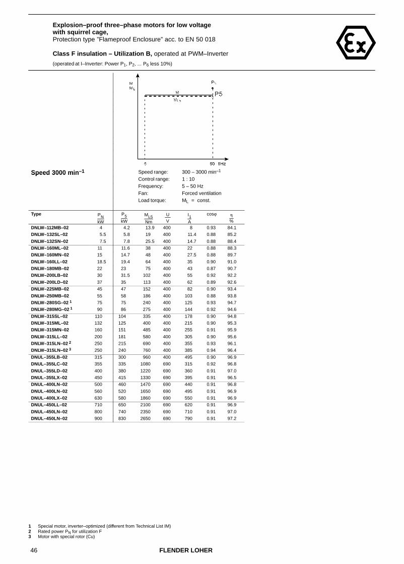
46 FLENDER LOHER
Explosion–proof three–phase motors for low voltage with squirrel cage,Protection type ”Flameproof Enclosure” acc. to EN 50 018
Class F insulation – Utilization B, operated at PWM–Inverter
(operated at I–Inverter: Power P1, P2, ... P6 less 10%)
Speed 3000 min–1 Speed range: 300 – 3000 min–1Speed 3000 minControl range: 1 : 10Frequency: 5 – 50 HzFan: Forced ventilation
Load torque: ML = const.
Type PNkW
P5kW
ML5Nm
U V
I1A
cosϕ �
%
DNLW–112MB–02 4 4.2 13.9 400 8 0.93 84.1
DNLW–132SL–02 5.5 5.8 19 400 11.4 0.88 85.2
DNLW–132SN–02 7.5 7.8 25.5 400 14.7 0.88 88.4
DNLW–160ML–02 11 11.6 38 400 22 0.88 88.3
DNLW–160MN–02 15 14.7 48 400 27.5 0.88 89.7
DNLW–160LL–02 18.5 19.4 64 400 35 0.90 91.0
DNLW–180MB–02 22 23 75 400 43 0.87 90.7
DNLW–200LB–02 30 31.5 102 400 55 0.92 92.2
DNLW–200LD–02 37 35 113 400 62 0.89 92.6
DNLW–225MB–02 45 47 152 400 82 0.90 93.4
DNLW–250MB–02 55 58 186 400 103 0.88 93.8
DNLW–280SG–02 1 75 75 240 400 125 0.93 94.7
DNLW–280MG–02 1 90 86 275 400 144 0.92 94.6
DNLW–315SL–02 110 104 335 400 178 0.90 94.8
DNLW–315ML–02 132 125 400 400 215 0.90 95.3
DNLW–315MN–02 160 151 485 400 255 0.91 95.9
DNLW–315LL–02 200 181 580 400 305 0.90 95.6
DNLW–315LN–02 2 250 215 690 400 355 0.93 96.1
DNLW–315LN–02 3 250 240 760 400 385 0.94 96.4
DNUL–355LB–02 315 300 960 400 495 0.90 96.9
DNUL–355LC–02 355 335 1080 690 315 0.92 96.8
DNUL–355LD–02 400 380 1220 690 360 0.91 97.0
DNUL–355LX–02 450 415 1330 690 395 0.91 96.5
DNUL–400LN–02 500 460 1470 690 440 0.91 96.8
DNUL–400LN–02 560 520 1650 690 495 0.91 96.9
DNUL–400LX–02 630 580 1860 690 550 0.91 96.9
DNUL–450LL–02 710 650 2100 690 620 0.91 96.9
DNUL–450LN–02 800 740 2350 690 710 0.91 97.0
DNUL–450LN–02 900 830 2650 690 790 0.91 97.2
1 Special motor, inverter–optimized (different from Technical List IM)2 Rated power PN for utilization F3 Motor with special rotor (Cu)

47FLENDER LOHER
Explosion–proof three–phase motors for low voltage with squirrel cage,Protection type ”Flameproof Enclosure” acc. to EN 50 018
Class F insulation – Utilization B, operated at PWM–Inverter
(operated at I–Inverter: Power P1, P2, ... P6 less 10%)
Speed 3000 min–1 Speed range: 3000 – 5200 min–1Speed 3000 minControl range: 10 : 17Frequency: 50 – 87 HzFan: Self–ventilation,
Forced ventilationLoad torque: ML = const./ ML � n2
Type PNkW
P6kW
ML6Nm
U V
I1A
cosϕ �
%
DNGW–071BG–02 0.37 0.54 1.1 400 1.68 0.75 66.3
DNGW–071BH–02 0.55 0.81 1.6 400 2.15 0.82 70.3
DNGW–080BG–02 0.75 1.1 2.2 400 2.75 0.79 76.7
DNGW–080BH–02 1.1 1.62 3.2 400 3.9 0.79 79.5
DNGW–090LX–02 1.5 2.15 4.2 400 5.1 0.82 77.2
DNGW–090LD–02 2.2 3.1 6 400 7 0.81 82.0
DNGW–100LB–02 3 4.4 8.5 400 9.4 0.86 81.9
DNGW–112MB–02 4 5.9 11.3 400 12.1 0.91 79.6
DNGW–132SL–02 5.5 8.1 15.4 400 17.7 0.86 79.9
DNGW–132SN–02 7.5 11 21 400 22 0.85 86.7
DNGW–160ML–02 11 15.8 30 400 32.5 0.86 83.8
DNGW–160MN–02 15 21.5 40 400 43 0.86 86.7
DNGW–160LL–02 18.5 26.5 50 400 50 0.88 88.9
DNGW–180MB–02 22 31.5 59 400 65 0.85 85.5
DNGW–200LB–02 30 38 71 400 72 0.90 87.4
DNGW–200LD–02 37 39 73 400 79 0.85 86.7
For mains operation the motor windings have to be Y–connected.
For inverter operation ∆–connection of the windings is required.
For the control range below 50 Hz the limit torques ML2, ML3, ML4 have to be observed (see Chapter 2.4.2.2)

48 FLENDER LOHER
Explosion–proof three–phase motors for low voltage with squirrel cage,Protection type ”Flameproof Enclosure” acc. to EN 50 018
Class F insulation – Utilization B, operated at PWM–Inverter
(operated at I–Inverter: Power P1, P2, ... P6 less 10%)
Speed 1500 min–1 Speed range: 150 – 1500 min–1 Speed range: 500 – 1500 min–1Speed 1500 minControl range: 1 : 10 Control range: 1 : 3Frequency: 5 – 50 Hz Frequency: 16.7 – 50 HzFan: Self–ventilation Fan: Self–ventilation
Load torque: ML � n2 Load torque: ML = const.
Type PNkW
P1kW
ML1Nm
U V
I1A
cosϕ �
%
P2kW
ML2Nm
U V
I1A
cosϕ �
%
DNGW–071BG–04 0.25 0.26 1.8 400 0.79 0.80 64.1 0.24 1.7 400 0.76 0.78 64.2
DNGW–071BH–04 0.37 0.39 2.8 400 1.16 0.80 65.0 0.34 2.5 400 1.07 0.76 65.3
DNGW–080BG–04 0.55 0.58 4.0 400 1.59 0.80 69.8 0.46 3.2 400 1.39 0.74 70.0
DNGW–080BH–04 0.75 0.75 5.2 400 1.92 0.81 72.9 0.57 4.0 400 1.60 0.75 73.4
DNGW–090LX–04 1.1 1.15 7.8 400 2.55 0.87 77.8 0.96 6.5 400 2.20 0.84 78.6
DNGW–090LD–04 1.5 1.57 10.7 400 3.55 0.87 76.6 1.30 8.9 400 3.05 0.83 77.4
DNGW–100LB–04 2.2 2.3 15.7 400 5.1 0.86 78.2 1.83 12.5 400 4.25 0.82 79.0
DNGW–100LD–04 3 3.0 20.5 400 6.9 0.81 80.6 2.30 15.7 400 5.8 0.74 80.8
DNGW–112MB–04 4 4.0 27.0 400 8.3 0.87 83.3 3.20 21.5 400 6.8 0.83 84.0
DNGW–132SL–04 5.5 5.8 38.5 400 11.4 0.88 86.3 4.85 32.5 400 9.7 0.85 86.8
DNGW–132ML–04 7.5 7.8 52 400 15.2 0.86 87.9 6.3 41.5 400 12.7 0.83 88.4
DNGW–160ML–04 11 11.5 75 400 22.5 0.86 89.3 9.3 61 400 18.5 0.83 89.7
DNGW–160LL–04 15 15.0 98 400 29.0 0.85 90.5 12.0 79 400 24.0 0.82 91.0
DNGW–180MB–04 18.5 19.1 125 400 35.5 0.87 91.1 15.7 103 400 30.0 0.85 91.3
DNGW–180LB–04 22 23.0 151 400 42.5 0.87 91.5 19.5 127 400 36.5 0.86 91.8
DNGW–200LB–04 30 30.0 197 400 54 0.88 92.3 24.0 155 400 44 0.87 92.6
DNGW–225SB–04 37 35.5 230 400 64 0.88 93.3 29.0 189 400 53 0.86 93.5
DNGW–225MB–04 45 43.5 280 400 81 0.85 93.4 35.5 230 400 68 0.82 93.5
DNGW–250MB–04 55 54 350 400 95 0.88 94.0 46.5 300 400 84 0.87 93.9
DNGW–280SG–04 75 75 485 400 132 0.88 94.7 62 400 400 111 0.87 94.7
DNGW–280MG–04 90 86 550 400 150 0.88 94.9 73 470 400 129 0.87 94.8
DNGW–315SL–04 110 104 670 400 190 0.85 95.2 94 600 400 174 0.83 95.2
DNGW–315ML–04 132 125 810 400 225 0.86 95.4 108 690 400 196 0.85 95.4
DNGW–315MN–04 160 152 980 400 270 0.86 95.7 129 830 400 235 0.84 95.7
DNGW–315LL–04 2 200 175 1130 400 320 0.84 95.7 148 950 400 280 0.82 95.6
DNGW–315LL–04 3 200 190 1220 400 340 0.86 95.8 167 1070 400 305 0.85 95.7
DNGW–315LM–04 2 250 220 1400 400 405 0.83 96.3 181 1160 400 345 0.80 96.2
DNGW–315LM–04 3 250 235 1520 400 420 0.85 96.0 210 1340 400 385 0.84 96.0
DNSL–355LB–04 280 265 1710 400 465 0.86 96.2 235 1510 400 420 0.85 96.2
DNSL–355LB–04 315 300 1920 400 520 0.86 96.4 265 1700 400 470 0.85 96.3
DNSL–355LC–04 355 335 2150 690 340 0.86 96.8 300 1910 690 305 0.85 96.7
DNSL–355LD–04 400 380 2450 690 380 0.86 96.9 335 2150 690 340 0.85 96.8
DNSL–355LN–04 450 430 2750 690 440 0.85 96.7 380 2400 690 390 0.84 96.7
DNSL–355LX–04 500 475 3050 690 480 0.85 96.9 420 2700 690 430 0.84 96.9
DNSL–400LN–04 560 530 3400 690 520 0.88 96.9 470 3000 690 470 0.87 96.8
DNSL–400LN–04 630 600 3850 690 590 0.88 96.8 530 3400 690 530 0.87 96.8
DNSL–400LX–04 710 670 4300 690 660 0.88 97.0 590 3800 690 590 0.87 97.0
DNSL–450LL–04 800 760 4850 690 750 0.88 97.1 670 4300 690 670 0.87 97.0
DNSL–450LN–04 900 860 5500 690 840 0.88 97.2 760 4850 690 750 0.87 97.1
DNSL–450LN–04 950 900 5800 690 880 0.88 97.3 800 5100 690 790 0.87 97.2
DNSL–500LL–04 1000 950 6100 690 930 0.88 97.0 840 5400 690 830 0.87 96.9
DNSL–500LL–04 1120 1060 6800 690 1040 0.88 97.2 940 6000 690 920 0.88 97.1
2 Rated power PN for utilization F3 Motor with special rotor (Cu)
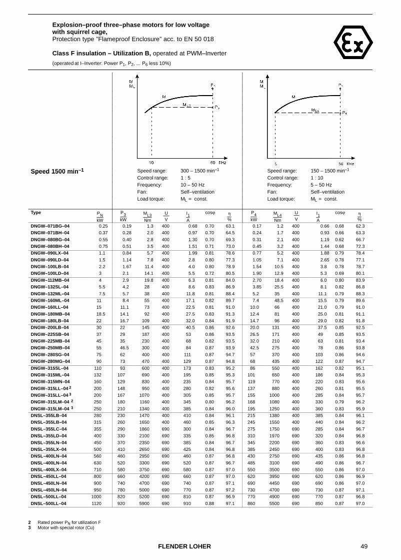
49FLENDER LOHER
Explosion–proof three–phase motors for low voltage with squirrel cage,Protection type ”Flameproof Enclosure” acc. to EN 50 018
Class F insulation – Utilization B, operated at PWM–Inverter
(operated at I–Inverter: Power P1, P2, ... P6 less 10%)
Speed 1500 min–1 Speed range: 300 – 1500 min–1 Speed range: 150 – 1500 min–1Speed 1500 minControl range: 1 : 5 Control range: 1 : 10Frequency: 10 – 50 Hz Frequency: 5 – 50 HzFan: Self–ventilation Fan: Self–ventilation
Load torque: ML = const. Load torque: ML = const.
Type PNkW
P3kW
ML3Nm
U V
I1A
cosϕ �
%
P4kW
ML4Nm
U V
I1A
cosϕ �
%
DNGW–071BG–04 0.25 0.19 1.3 400 0.68 0.70 63.1 0.17 1.2 400 0.66 0.68 62.3
DNGW–071BH–04 0.37 0.28 2.0 400 0.97 0.70 64.5 0.24 1.7 400 0.93 0.66 63.3
DNGW–080BG–04 0.55 0.40 2.8 400 1.30 0.70 69.3 0.31 2.1 400 1.19 0.62 66.7
DNGW–080BH–04 0.75 0.51 3.5 400 1.51 0.71 73.0 0.45 3.2 400 1.44 0.68 72.3
DNGW–090LX–04 1.1 0.84 5.7 400 1.99 0.81 78.6 0.77 5.2 400 1.88 0.79 78.4
DNGW–090LD–04 1.5 1.14 7.8 400 2.8 0.80 77.3 1.05 7.1 400 2.65 0.78 77.1
DNGW–100LB–04 2.2 1.67 11.4 400 4.0 0.80 78.9 1.54 10.5 400 3.8 0.78 78.7
DNGW–100LD–04 3 2.1 14.1 400 5.5 0.72 80.5 1.90 12.9 400 5.3 0.69 80.1
DNGW–112MB–04 4 2.9 19.8 400 6.3 0.81 84.0 2.70 18.4 400 6.0 0.80 83.9
DNGW–132SL–04 5.5 4.2 28 400 8.6 0.83 86.9 3.85 25.5 400 8.1 0.82 86.8
DNGW–132ML–04 7.5 5.7 38 400 11.8 0.81 88.4 5.2 35 400 11.1 0.79 88.3
DNGW–160ML–04 11 8.4 55 400 17.1 0.82 89.7 7.4 48.5 400 15.5 0.79 89.6
DNGW–160LL–04 15 11.1 73 400 22.5 0.81 91.0 10.0 66 400 21.0 0.79 91.0
DNGW–180MB–04 18.5 14.1 92 400 27.5 0.83 91.3 12.4 81 400 25.0 0.81 91.1
DNGW–180LB–04 22 16.7 109 400 32.0 0.84 91.9 14.7 96 400 29.0 0.82 91.8
DNGW–200LB–04 30 22 145 400 40.5 0.86 92.6 20.0 131 400 37.5 0.85 92.5
DNGW–225SB–04 37 29 187 400 53 0.86 93.5 26.5 171 400 49 0.85 93.5
DNGW–225MB–04 45 35 230 400 68 0.82 93.5 32.0 210 400 63 0.81 93.4
DNGW–250MB–04 55 46.5 300 400 84 0.87 93.9 42.5 275 400 78 0.86 93.8
DNGW–280SG–04 75 62 400 400 111 0.87 94.7 57 370 400 103 0.86 94.6
DNGW–280MG–04 90 73 470 400 129 0.87 94.8 68 435 400 122 0.87 94.7
DNGW–315SL–04 110 93 600 400 173 0.83 95.2 86 550 400 162 0.82 95.1
DNGW–315ML–04 132 107 690 400 195 0.85 95.3 101 650 400 186 0.84 95.3
DNGW–315MN–04 160 129 830 400 235 0.84 95.7 119 770 400 220 0.83 95.6
DNGW–315LL–04 2 200 148 950 400 280 0.82 95.6 137 880 400 260 0.81 95.5
DNGW–315LL–04 3 200 167 1070 400 305 0.85 95.7 155 1000 400 285 0.84 95.7
DNGW–315LM–04 2 250 180 1160 400 345 0.80 96.2 168 1080 400 330 0.79 96.2
DNGW–315LM–04 3 250 210 1340 400 385 0.84 96.0 195 1250 400 360 0.83 95.9
DNSL–355LB–04 280 230 1470 400 410 0.84 96.1 215 1380 400 385 0.84 96.1
DNSL–355LB–04 315 260 1650 400 460 0.85 96.3 245 1550 400 440 0.84 96.2
DNSL–355LC–04 355 290 1860 690 300 0.84 96.7 275 1750 690 285 0.84 96.7
DNSL–355LD–04 400 330 2100 690 335 0.85 96.8 310 1970 690 320 0.84 96.8
DNSL–355LN–04 450 370 2350 690 385 0.84 96.7 345 2200 690 360 0.83 96.6
DNSL–355LX–04 500 410 2650 690 425 0.84 96.8 385 2450 690 400 0.83 96.8
DNSL–400LN–04 560 460 2950 690 460 0.87 96.8 430 2750 690 435 0.86 96.8
DNSL–400LN–04 630 520 3300 690 520 0.87 96.7 485 3100 690 490 0.86 96.7
DNSL–400LX–04 710 580 3750 690 580 0.87 97.0 550 3500 690 550 0.86 97.0
DNSL–450LL–04 800 660 4200 690 660 0.87 97.0 620 3950 690 620 0.86 96.9
DNSL–450LN–04 900 740 4700 690 740 0.87 97.1 690 4450 690 690 0.86 97.0
DNSL–450LN–04 950 780 5000 690 770 0.87 97.2 730 4700 690 730 0.87 97.1
DNSL–500LL–04 1000 820 5200 690 810 0.87 96.9 770 4900 690 770 0.87 96.8
DNSL–500LL–04 1120 920 5900 690 910 0.88 97.1 860 5500 690 850 0.87 97.0
2 Rated power PN for utilization F3 Motor with special rotor (Cu)
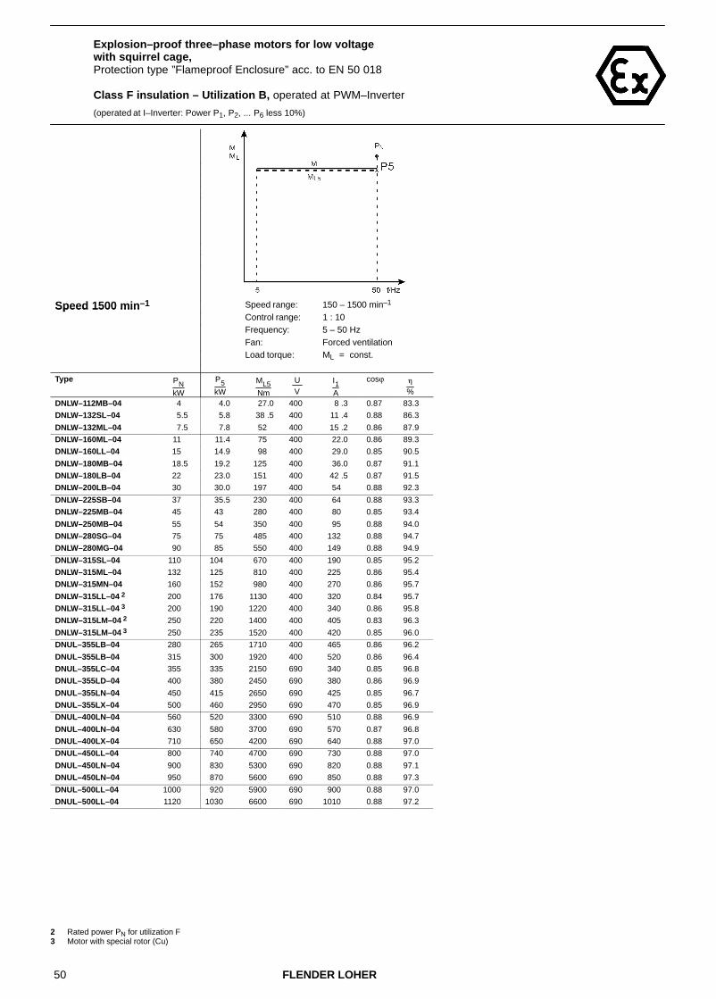
50 FLENDER LOHER
Explosion–proof three–phase motors for low voltage with squirrel cage,Protection type ”Flameproof Enclosure” acc. to EN 50 018
Class F insulation – Utilization B, operated at PWM–Inverter
(operated at I–Inverter: Power P1, P2, ... P6 less 10%)
Speed 1500 min–1 Speed range: 150 – 1500 min–1Speed 1500 minControl range: 1 : 10Frequency: 5 – 50 HzFan: Forced ventilation
Load torque: ML = const.
Type PNkW
P5kW
ML5Nm
U V
I1A
cosϕ �
%
DNLW–112MB–04 4 4.0 27.0 400 8 .3 0.87 83.3
DNLW–132SL–04 5.5 5.8 38 .5 400 11 .4 0.88 86.3
DNLW–132ML–04 7.5 7.8 52 400 15 .2 0.86 87.9
DNLW–160ML–04 11 11.4 75 400 22.0 0.86 89.3
DNLW–160LL–04 15 14.9 98 400 29.0 0.85 90.5
DNLW–180MB–04 18.5 19.2 125 400 36.0 0.87 91.1
DNLW–180LB–04 22 23.0 151 400 42 .5 0.87 91.5
DNLW–200LB–04 30 30.0 197 400 54 0.88 92.3
DNLW–225SB–04 37 35.5 230 400 64 0.88 93.3
DNLW–225MB–04 45 43 280 400 80 0.85 93.4
DNLW–250MB–04 55 54 350 400 95 0.88 94.0
DNLW–280SG–04 75 75 485 400 132 0.88 94.7
DNLW–280MG–04 90 85 550 400 149 0.88 94.9
DNLW–315SL–04 110 104 670 400 190 0.85 95.2
DNLW–315ML–04 132 125 810 400 225 0.86 95.4
DNLW–315MN–04 160 152 980 400 270 0.86 95.7
DNLW–315LL–04 2 200 176 1130 400 320 0.84 95.7
DNLW–315LL–04 3 200 190 1220 400 340 0.86 95.8
DNLW–315LM–04 2 250 220 1400 400 405 0.83 96.3
DNLW–315LM–04 3 250 235 1520 400 420 0.85 96.0
DNUL–355LB–04 280 265 1710 400 465 0.86 96.2
DNUL–355LB–04 315 300 1920 400 520 0.86 96.4
DNUL–355LC–04 355 335 2150 690 340 0.85 96.8
DNUL–355LD–04 400 380 2450 690 380 0.86 96.9
DNUL–355LN–04 450 415 2650 690 425 0.85 96.7
DNUL–355LX–04 500 460 2950 690 470 0.85 96.9
DNUL–400LN–04 560 520 3300 690 510 0.88 96.9
DNUL–400LN–04 630 580 3700 690 570 0.87 96.8
DNUL–400LX–04 710 650 4200 690 640 0.88 97.0
DNUL–450LL–04 800 740 4700 690 730 0.88 97.0
DNUL–450LN–04 900 830 5300 690 820 0.88 97.1
DNUL–450LN–04 950 870 5600 690 850 0.88 97.3
DNUL–500LL–04 1000 920 5900 690 900 0.88 97.0
DNUL–500LL–04 1120 1030 6600 690 1010 0.88 97.2
2 Rated power PN for utilization F3 Motor with special rotor (Cu)
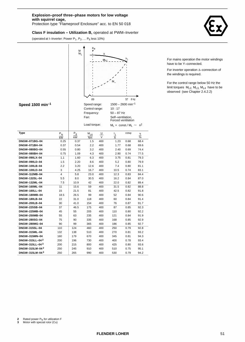
51FLENDER LOHER
Explosion–proof three–phase motors for low voltage with squirrel cage,Protection type ”Flameproof Enclosure” acc. to EN 50 018
Class F insulation – Utilization B, operated at PWM–Inverter
(operated at I–Inverter: Power P1, P2, ... P6 less 10%)
Speed 1500 min–1 Speed range: 1500 – 2600 min–1Speed 1500 minControl range: 10 : 17Frequency: 50 – 87 HzFan: Self–ventilation,
Forced ventilationLoad torque: ML = const./ ML � n2
Type PNkW
P6kW
ML6Nm
U V
I1A
cosϕ �
%
DNGW–071BG–04 0.25 0.37 1.5 400 1.23 0.68 68.4
DNGW–071BH–04 0.37 0.54 2.2 400 1.77 0.68 69.6
DNGW–080BG–04 0.55 0.80 3.2 400 2.40 0.69 74.4
DNGW–080BH–04 0.75 1.09 4.3 400 2.90 0.74 77.5
DNGW–090LX–04 1.1 1.60 6.3 400 3.75 0.81 79.3
DNGW–090LD–04 1.5 2.20 8.6 400 5.2 0.80 79.9
DNGW–100LB–04 2.2 3.20 12.6 400 7.4 0.80 81.1
DNGW–100LD–04 3 4.25 16.7 400 10.5 0.74 83.1
DNGW–112MB–04 4 5.8 23.0 400 12.3 0.83 84.4
DNGW–132SL–04 5.5 8.0 30.5 400 16.2 0.84 87.0
DNGW–132ML–04 7.5 10.9 42 400 22.0 0.82 89.4
DNGW–160ML–04 11 15.6 59 400 31.5 0.82 88.8
DNGW–160LL–04 15 21.5 81 400 42.5 0.82 91.8
DNGW–180MB–04 18.5 26.5 99 400 52 0.84 90.6
DNGW–180LB–04 22 31.0 118 400 60 0.84 91.4
DNGW–200LB–04 30 41.0 154 400 76 0.87 91.7
DNGW–225SB–04 37 46.5 175 400 87 0.85 92.3
DNGW–225MB–04 45 55 205 400 110 0.80 92.2
DNGW–250MB–04 55 63 235 400 121 0.84 91.9
DNGW–280SG–04 75 90 335 400 168 0.85 92.9
DNGW–280MG–04 90 99 365 400 186 0.85 92.7
DNGW–315SL–04 110 124 460 400 250 0.79 92.8
DNGW–315ML–04 132 138 510 400 270 0.81 93.2
DNGW–315MN–04 160 179 670 400 345 0.81 94.3
DNGW–315LL–04 2 200 196 730 400 400 0.78 93.4
DNGW–315LL–04 3 200 215 800 400 425 0.80 93.6
DNGW–315LM–04 2 250 245 910 400 510 0.75 95.1
DNGW–315LM–04 3 250 265 990 400 530 0.79 94.2
2 Rated power PN for utilization F3 Motor with special rotor (Cu)
For mains operation the motor windings have to be Y–connected.
For inverter operation ∆–connection of the windings is required.
For the control range below 50 Hz the limit torques ML2, ML3, ML4 have to be observed (see Chapter 2.4.2.2)
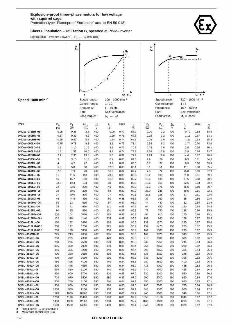
52 FLENDER LOHER
Explosion–proof three–phase motors for low voltage with squirrel cage,Protection type ”Flameproof Enclosure” acc. to EN 50 018
Class F insulation – Utilization B, operated at PWM–Inverter
(operated at I–Inverter: Power P1, P2, ... P6 less 10%)
Speed 1000 min–1 Speed range: 100 – 1000 min–1 Speed range: 330 – 1000 min–1Speed 1000 minControl range: 1 : 10 Control range: 1 : 3Frequency: 5 – 50 Hz Frequency: 16.7 – 50 HzFan: Self–ventilation Fan: Self–ventilation
Load torque: ML � n2 Load torque: ML = const.
Type PNkW
P1kW
ML1Nm
U V
I1A
cosϕ �
%
P2kW
ML2Nm
U V
I1A
cosϕ �
%
DNGW–071BH–06 0.25 0.26 2.8 400 0.90 0.77 58.9 0.20 2.2 400 0.79 0.68 58.9
DNGW–080BG–06 0.37 0.39 4.2 400 1.29 0.76 62.6 0.29 3.2 400 1.11 0.67 63.1
DNGW–080BH–06 0.55 0.52 5.6 400 1.64 0.74 66.8 0.36 3.9 400 1.39 0.63 65.8
DNGW–090LX–06 0.75 0.78 8.3 400 2.1 0.79 71.4 0.58 6.2 400 1.74 0.70 73.0
DNGW–090LD–06 1.1 1.10 11.5 400 3.3 0.73 70.9 0.73 7.6 400 2.8 0.59 70.1
DNGW–100LB–06 1.5 1.57 16.0 400 4.4 0.74 74.2 1.26 12.8 400 3.9 0.68 73.7
DNGW–112MB–06 2.2 2.30 23.5 400 5.5 0.81 77.9 1.83 18.6 400 4.6 0.77 78.6
DNGW–132SL–06 3 3.15 31.5 400 6.7 0.83 84.6 2.9 29 400 6.3 0.81 84.8
DNGW–132ML–06 4 4.2 42 400 9.2 0.82 83.5 3.7 37 400 8.3 0.80 83.8
DNGW–132MN–06 5.5 5.8 58 400 12.3 0.83 85.1 5.1 51 400 11.1 0.80 85.5
DNGW–160ML–06 7.5 7.9 78 400 16.0 0.84 87.2 7.3 72 400 15.0 0.83 87.3
DNGW–160LL–06 11 11.5 113 400 23.0 0.83 88.9 10.2 100 400 21.0 0.81 89.1
DNGW–180LB–06 15 15.7 156 400 31.5 0.82 89.7 13.4 133 400 27.5 0.80 90.1
DNGW–200LB–06 18.5 19.4 193 400 38 0.85 89.5 16.6 165 400 32.5 0.84 90.2
DNGW–200LD–06 22 22.5 220 400 45 0.82 90.2 17.3 171 400 35.5 0.80 90.7
DNGW–225MB–06 30 30.5 300 400 59 0.83 92.0 25.0 245 400 49.5 0.81 92.1
DNGW–250MB–06 37 39.0 375 400 77 0.82 92.1 33.5 325 400 67 0.81 92.0
DNGW–280SG–06 45 44.5 430 400 80 0.88 93.3 37 360 400 68 0.86 93.4
DNGW–280MG–06 55 53 510 400 97 0.87 93.0 44 430 400 82 0.85 92.9
DNGW–315SL–06 75 71 690 400 131 0.85 94.3 64 620 400 120 0.84 94.3
DNGW–315ML–06 90 85 830 400 151 0.87 95.3 77 750 400 138 0.86 95.3
DNGW–315MM–06 110 104 1010 400 185 0.87 95.1 95 910 400 170 0.86 95.1
DNGW–315MN–06 2 132 118 1140 400 205 0.88 95.5 102 980 400 179 0.87 95.5
DNGW–315LL–06 160 152 1470 400 265 0.88 95.6 131 1270 400 230 0.87 95.6
DNGW–315LM–06 2 200 177 1700 400 325 0.84 95.9 152 1470 400 285 0.82 95.8
DNGW–315LM–06 3 200 190 1830 400 330 0.88 95.9 164 1580 400 290 0.87 95.9
DNSL–355MD–06 225 215 2050 400 385 0.84 96.0 189 1820 400 345 0.82 95.9
DNSL–355LB–06 250 235 2300 400 420 0.84 96.3 210 2000 400 385 0.82 96.2
DNSL–355LC–06 280 265 2550 690 270 0.85 96.3 235 2250 690 245 0.84 96.3
DNSL–355LD–06 315 300 2900 690 310 0.84 96.4 265 2550 690 280 0.82 96.3
DNSL–355LN–06 355 335 3250 690 340 0.85 96.4 295 2850 690 305 0.84 96.4
DNSL–355LN–06 400 380 3650 690 395 0.83 96.5 325 3150 690 345 0.82 96.5
DNSL–400LL–06 400 380 3650 690 395 0.83 96.5 335 3200 690 355 0.82 96.5
DNSL–400LN–06 450 425 4100 690 440 0.84 96.6 380 3650 690 400 0.83 96.6
DNSL–400LN–06 500 475 4550 690 490 0.84 96.7 415 4000 690 435 0.83 96.6
DNSL–450LL–06 560 530 5100 690 540 0.85 96.9 470 4500 690 485 0.84 96.8
DNSL–450LL–06 630 600 5700 690 610 0.85 97.0 530 5100 690 550 0.84 96.9
DNSL–450LN–06 710 670 6500 690 680 0.85 97.0 600 5700 690 620 0.84 97.0
DNSL–450LN–06 800 740 7100 690 760 0.84 97.1 650 6300 690 680 0.83 97.1
DNSL–500LL–06 900 860 8200 690 880 0.85 97.0 760 7300 690 780 0.84 96.9
DNSL–500LN–06 1000 950 9100 690 970 0.85 97.1 840 8100 690 860 0.84 97.0
DNSL–500LN–06 1120 1060 10200 690 1060 0.86 97.2 940 9000 690 940 0.86 97.1
DNSL–560LL–06 1250 1190 11400 690 1170 0.88 97.2 1050 10100 690 1040 0.87 97.2
DNSL–560LL–06 1400 1330 12800 690 1330 0.86 97.2 1180 11300 690 1200 0.85 97.1
DNSL–560LN–06 1600 1520 14600 690 1490 0.88 97.4 1340 12900 690 1320 0.87 97.3 2 Rated power PN for utilization F3 Motor with special rotor (Cu)

53FLENDER LOHER
Explosion–proof three–phase motors for low voltage with squirrel cage,Protection type ”Flameproof Enclosure” acc. to EN 50 018
Class F insulation – Utilization B, operated at PWM–Inverter
(operated at I–Inverter: Power P1, P2, ... P6 less 10%)
Speed 1000 min–1 Speed range: 200 – 1000 min–1 Speed range: 100 – 1000 min–1Speed 1000 minControl range: 1 : 5 Control range: 1 : 10Frequency: 10 – 50 Hz Frequency: 5 – 50 HzFan: Self–ventilation Fan: Self–ventilation
Load torque: ML = const. Load torque: ML = const.
Type PNkW
P3kW
ML3Nm
U V
I1A
cosϕ �
%
P4kW
ML4Nm
U V
I1A
cosϕ �
%
DNGW–071BH–06 0.25 0.16 1.7 400 0.74 0.61 56.6 0.14 1.4 400 0.72 0.60 55.0
DNGW–080BG–06 0.37 0.23 2.5 400 1.03 0.60 61.2 0.21 2.1 400 1.01 0.59 60.0
DNGW–080BH–06 0.55 0.29 3.2 400 1.32 0.57 63.6 0.28 2.8 400 1.20 0.56 63.5
DNGW–090LX–06 0.75 0.51 5.4 400 1.65 0.66 72.8 0.44 4.4 400 1.56 0.62 71.0
DNGW–090LD–06 1.1 0.66 6.6 400 2.7 0.57 69.3 0.62 6.1 400 2.65 0.54 68.0
DNGW–100LB–06 1.5 1.09 11.1 400 3.7 0.64 72.8 0.88 8.9 400 3.45 0.57 70.6
DNGW–112MB–06 2.2 1.67 17 400 4.35 0.75 78.5 1.53 15.5 400 4.1 0.73 78.2
DNGW–132SL–06 3 2.3 23 400 5.3 0.77 84.8 2.1 21.0 400 5.1 0.73 84.6
DNGW–132ML–06 4 3.05 30.5 400 7.3 0.75 83.8 2.8 28.0 400 6.9 0.74 83.6
DNGW–132MN–06 5.5 4.2 42 400 9.7 0.76 85.5 3.85 38.5 400 9.2 0.74 85.3
DNGW–160ML–06 7.5 5.7 56 400 12.5 0.78 87.2 5 49.5 400 11.5 0.75 86.9
DNGW–160LL–06 11 8.4 82 400 18.4 0.77 89.0 7.4 72 400 17 0.74 88.8
DNGW–180LB–06 15 11.4 113 400 24.5 0.77 90.3 10.1 99 400 23 0.74 90.2
DNGW–200LB–06 18.5 14.1 140 400 28 0.83 90.5 12.4 123 400 25 0.81 90.5
DNGW–200LD–06 22 16.1 159 400 34 0.78 90.7 14.7 146 400 31.5 0.77 90.6
DNGW–225MB–06 30 25 245 400 49.5 0.81 92.1 22.5 220 400 46 0.79 92.1
DNGW–250MB–06 37 31.5 305 400 64 0.80 91.9 28.5 275 400 59 0.78 91.7
DNGW–280SG–06 45 37 355 400 68 0.86 93.4 34 330 400 63 0.85 93.3
DNGW–280MG–06 55 44.5 430 400 83 0.85 92.9 41 395 400 78 0.84 92.8
DNGW–315SL–06 75 64 620 400 120 0.84 94.3 58 560 400 110 0.82 94.2
DNGW–315ML–06 90 76 740 400 137 0.86 95.3 70 680 400 127 0.85 95.3
DNGW–315MM–06 110 93 900 400 167 0.86 95.1 86 830 400 156 0.85 95.1
DNGW–315MN–06 2 132 101 980 400 178 0.87 95.5 94 910 400 167 0.87 95.5
DNGW–315LL–06 160 131 1260 400 230 0.87 95.6 120 1160 400 215 0.86 95.6
DNGW–315LM–06 2 200 152 1470 400 285 0.82 95.8 141 1360 400 270 0.81 95.8
DNGW–315LM–06 3 200 164 1580 400 290 0.87 95.9 151 1460 400 270 0.86 95.9
DNSL–355MD–06 225 184 1770 400 340 0.82 95.9 173 1670 400 325 0.81 95.8
DNSL–355LB–06 250 205 1970 400 375 0.82 96.2 192 1850 400 355 0.81 96.1
DNSL–355LC–06 280 230 2200 690 240 0.83 96.3 215 2050 690 225 0.83 96.2
DNSL–355LD–06 315 260 2500 690 275 0.82 96.3 240 2300 690 265 0.81 96.3
DNSL–355LN–06 355 290 2800 690 300 0.84 96.4 275 2650 690 285 0.84 96.4
DNSL–355LN–06 400 325 3150 690 345 0.82 96.5 300 2900 690 325 0.81 96.4
DNSL–400LL–06 400 330 3150 690 350 0.82 96.4 310 2950 690 330 0.81 96.4
DNSL–400LN–06 450 370 3550 690 390 0.82 96.6 345 3350 690 370 0.81 96.5
DNSL–400LN–06 500 410 3950 690 430 0.82 96.6 385 3700 690 410 0.82 96.6
DNSL–450LL–06 560 460 4400 690 475 0.83 96.8 430 4150 690 450 0.83 96.7
DNSL–450LL–06 630 520 4950 690 540 0.84 96.9 485 4650 690 510 0.83 96.8
DNSL–450LN–06 710 580 5600 690 600 0.84 97.0 550 5300 690 570 0.83 96.9
DNSL–450LN–06 800 660 6300 690 690 0.83 97.1 620 5900 690 650 0.82 97.0
DNSL–500LL–06 900 740 7100 690 760 0.84 96.9 690 6700 690 710 0.84 96.8
DNSL–500LN–06 1000 820 7900 690 840 0.84 96.9 770 7400 690 800 0.84 96.9
DNSL–500LN–06 1120 920 8800 690 920 0.86 97.1 860 8300 690 870 0.86 97.1
DNSL–560LL–06 1250 1030 9800 690 1020 0.87 97.1 960 9200 690 950 0.87 97.1
DNSL–560LL–06 1400 1150 11000 690 1170 0.85 97.1 1080 10300 690 1110 0.84 97.0
DNSL–560LN–06 1600 1310 12600 690 1290 0.87 97.3 1230 11800 690 1220 0.87 97.2 2 Rated power PN for utilization F3 Motor with special rotor (Cu)
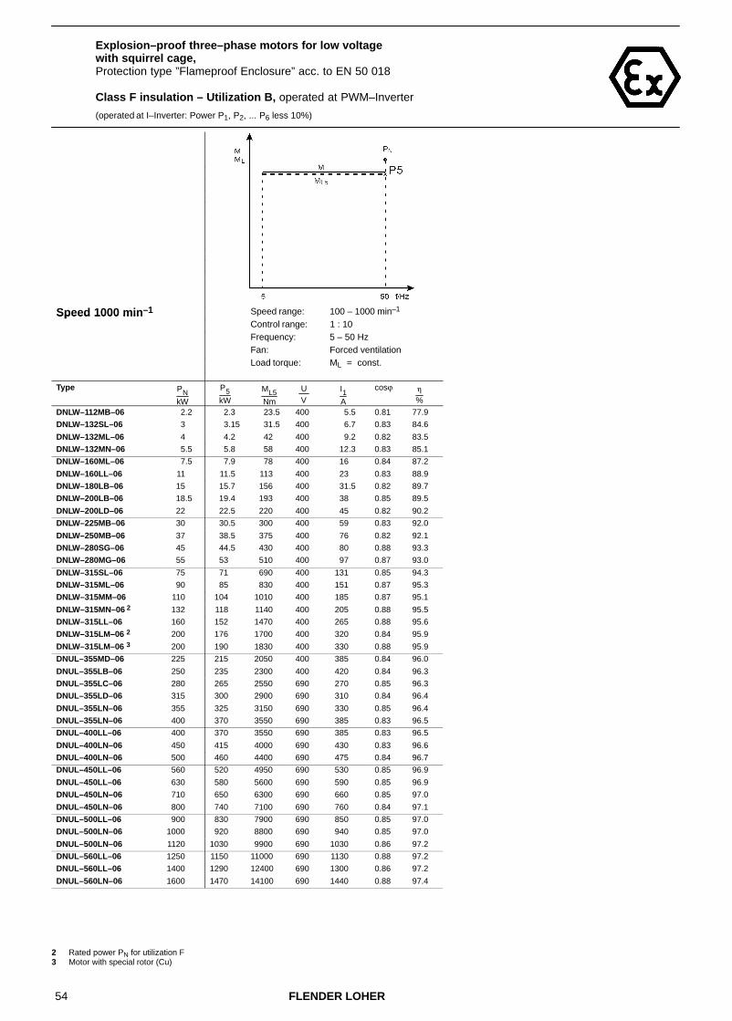
54 FLENDER LOHER
Explosion–proof three–phase motors for low voltage with squirrel cage,Protection type ”Flameproof Enclosure” acc. to EN 50 018
Class F insulation – Utilization B, operated at PWM–Inverter
(operated at I–Inverter: Power P1, P2, ... P6 less 10%)
Speed 1000 min–1 Speed range: 100 – 1000 min–1Speed 1000 minControl range: 1 : 10Frequency: 5 – 50 HzFan: Forced ventilation
Load torque: ML = const.
Type PNkW
P5kW
ML5Nm
U V
I1A
cosϕ �
%
DNLW–112MB–06 2.2 2.3 23.5 400 5.5 0.81 77.9
DNLW–132SL–06 3 3.15 31.5 400 6.7 0.83 84.6
DNLW–132ML–06 4 4.2 42 400 9.2 0.82 83.5
DNLW–132MN–06 5.5 5.8 58 400 12.3 0.83 85.1
DNLW–160ML–06 7.5 7.9 78 400 16 0.84 87.2
DNLW–160LL–06 11 11.5 113 400 23 0.83 88.9
DNLW–180LB–06 15 15.7 156 400 31.5 0.82 89.7
DNLW–200LB–06 18.5 19.4 193 400 38 0.85 89.5
DNLW–200LD–06 22 22.5 220 400 45 0.82 90.2
DNLW–225MB–06 30 30.5 300 400 59 0.83 92.0
DNLW–250MB–06 37 38.5 375 400 76 0.82 92.1
DNLW–280SG–06 45 44.5 430 400 80 0.88 93.3
DNLW–280MG–06 55 53 510 400 97 0.87 93.0
DNLW–315SL–06 75 71 690 400 131 0.85 94.3
DNLW–315ML–06 90 85 830 400 151 0.87 95.3
DNLW–315MM–06 110 104 1010 400 185 0.87 95.1
DNLW–315MN–06 2 132 118 1140 400 205 0.88 95.5
DNLW–315LL–06 160 152 1470 400 265 0.88 95.6
DNLW–315LM–06 2 200 176 1700 400 320 0.84 95.9
DNLW–315LM–06 3 200 190 1830 400 330 0.88 95.9
DNUL–355MD–06 225 215 2050 400 385 0.84 96.0
DNUL–355LB–06 250 235 2300 400 420 0.84 96.3
DNUL–355LC–06 280 265 2550 690 270 0.85 96.3
DNUL–355LD–06 315 300 2900 690 310 0.84 96.4
DNUL–355LN–06 355 325 3150 690 330 0.85 96.4
DNUL–355LN–06 400 370 3550 690 385 0.83 96.5
DNUL–400LL–06 400 370 3550 690 385 0.83 96.5
DNUL–400LN–06 450 415 4000 690 430 0.83 96.6
DNUL–400LN–06 500 460 4400 690 475 0.84 96.7
DNUL–450LL–06 560 520 4950 690 530 0.85 96.9
DNUL–450LL–06 630 580 5600 690 590 0.85 96.9
DNUL–450LN–06 710 650 6300 690 660 0.85 97.0
DNUL–450LN–06 800 740 7100 690 760 0.84 97.1
DNUL–500LL–06 900 830 7900 690 850 0.85 97.0
DNUL–500LN–06 1000 920 8800 690 940 0.85 97.0
DNUL–500LN–06 1120 1030 9900 690 1030 0.86 97.2
DNUL–560LL–06 1250 1150 11000 690 1130 0.88 97.2
DNUL–560LL–06 1400 1290 12400 690 1300 0.86 97.2
DNUL–560LN–06 1600 1470 14100 690 1440 0.88 97.4
2 Rated power PN for utilization F3 Motor with special rotor (Cu)

55FLENDER LOHER
Explosion–proof three–phase motors for low voltage with squirrel cage,Protection type ”Flameproof Enclosure” acc. to EN 50 018
Class F insulation – Utilization B, operated at PWM–Inverter
(operated at I–Inverter: Power P1, P2, ... P6 less 10%)
Speed 1000 min–1 Speed range: 1000 – 1730 min–1Speed 1000 minControl range: 10 : 17Frequency: 50 – 87 HzFan: Self–ventilation,
Forced ventilationLoad torque: ML = const./ ML � n2
Type PNkW
P6kW
ML6Nm
U V
I1A
cosϕ �
%
DNGW–071BH–06 0.25 0.37 2.3 400 1.41 0.64 64.3
DNGW–080BG–06 0.37 0.54 3.4 400 1.97 0.63 69.4
DNGW–080BH–06 0.55 0.76 4.8 400 2.6 0.64 72.1
DNGW–090LX–06 0.75 1.09 6.7 400 3.15 0.69 77.6
DNGW–090LD–06 1.1 1.6 9.6 400 5.2 0.62 77.0
DNGW–100LB–06 1.5 2.2 12.8 400 6.8 0.65 77.1
DNGW–112MB–06 2.2 3.2 18.8 400 8.2 0.75 79.0
DNGW–132SL–06 3 4.35 25 400 9.9 0.78 84.9
DNGW–132ML–06 4 5.8 33.5 400 13.4 0.76 85.5
DNGW–132MN–06 5.5 8 46 400 17.9 0.77 86.9
DNGW–160ML–06 7.5 10.7 61 400 23 0.79 87.8
DNGW–160LL–06 11 15.6 88 400 33.5 0.78 89.4
DNGW–180LB–06 15 21.5 122 400 45 0.78 91.4
DNGW–200LB–06 18.5 26.5 151 400 52 0.83 90.6
DNGW–200LD–06 22 30 170 400 62 0.79 91.0
DNGW–225MB–06 30 39 220 400 80 0.79 91.4
DNGW–250MB–06 37 45.5 255 400 99 0.77 89.1
DNGW–280SG–06 45 55 305 400 104 0.84 92.7
DNGW–280MG–06 55 61 340 400 122 0.81 90.8
DNGW–315SL–06 75 94 520 400 184 0.81 92.8
DNGW–315ML–06 90 112 630 400 210 0.84 94.7
DNGW–315MM–06 110 137 760 400 255 0.84 94.4
DNGW–315MN–06 2 132 143 800 400 260 0.85 94.9
DNGW–315LL–06 160 195 1090 400 350 0.86 95.3
DNGW–315LM–06 2 200 196 1090 400 400 0.77 94.9
DNGW–315LM–06 3 200 240 1320 400 435 0.85 95.1
2 Rated power PN for utilization F3 Motor with special rotor (Cu)
For mains operation the motor windings have to be Y–connected.
For inverter operation ∆–connection of the windings is required.
For the control range below 50 Hz the limit torques ML2, ML3, ML4 have to be observed (see Chapter 2.4.2.2)

56 FLENDER LOHER
Explosion–proof three–phase motors for low voltage with squirrel cage,Protection type ”Flameproof Enclosure” acc. to EN 50 018
Class F insulation – Utilization B, operated at PWM–Inverter
(operated at I–Inverter: Power P1, P2, ... P6 less 10%)
Speed 750 min–1 Speed range: 75 – 750 min–1 Speed range: 250 – 750 min–1Speed 750 minControl range: 1 : 10 Control range: 1 : 3Frequency: 5 – 50 Hz Frequency: 16.7 – 50 HzFan: Self–ventilation Fan: Self–ventilation
Load torque: ML � n2 Load torque: ML = const.
Type PNkW
P1kW
ML1Nm
U V
I1A
cosϕ �
%
P2kW
ML2Nm
U V
I1A
cosϕ �
%
DNGW–071BH–08 0.12 0.13 1.9 400 0.60 0.70 49.8 0.12 1.8 400 0.57 0.67 50.0
DNGW–080BH–08 0.25 0.26 3.8 400 1.07 0.68 57.4 0.22 3.3 400 1.01 0.63 57.3DNGW–090LX–08 0.37 0.39 5.5 400 1.43 0.68 63.1 0.36 5.0 400 1.37 0.66 63.1
DNGW–090LD–08 0.55 0.58 8.2 400 1.94 0.70 67.0 0.53 7.5 400 1.83 0.68 67.3DNGW–100LB–08 0.75 0.79 10.7 400 2.40 0.72 70.4 0.73 9.9 400 2.30 0.70 70.4
DNGW–100LD–08 1.1 1.10 15.1 400 3.20 0.74 72.0 0.80 11.0 400 2.70 0.65 71.3
DNGW–112MB–08 1.5 1.57 21.5 400 4.35 0.74 74.5 1.31 17.9 400 3.85 0.70 75.0DNGW–132SL–08 2.2 2.30 31 400 5.8 0.74 81.9 2.15 28.5 400 5.5 0.72 82.0
DNGW–132ML–08 3 3.15 42 400 7.8 0.74 83.6 2.9 39 400 7.3 0.72 83.8DNGW–160ML–08 4 4.2 56 400 9.6 0.77 85.0 3.9 52 400 9.0 0.76 85.4
DNGW–160MN–08 5.5 5.8 76 400 13.5 0.75 86.2 5.3 70 400 12.7 0.73 86.4DNGW–160LL–08 7.5 7.9 104 400 17.9 0.77 85.9 7.3 96 400 16.9 0.76 86.1
DNGW–180LB–08 11 11.6 153 400 24.0 0.82 88.1 10.4 138 400 22.0 0.80 88.5
DNGW–200LB–08 15 15.7 210 400 33.5 0.79 87.7 13.6 183 400 29.5 0.78 88.6DNGW–225SB–08 18.5 19.4 255 400 40.5 0.80 89.0 16.4 215 400 35.0 0.78 89.6
DNGW–225MB–08 22 23.0 305 400 49 0.78 89.9 21.5 280 400 46.5 0.77 90.0DNGW–250MB–08 30 31.5 410 400 62 0.82 91.1 28.5 375 400 57 0.81 91.2
DNGW–280SG–08 37 37.5 490 400 74 0.81 92.3 31.0 400 400 63 0.79 92.4
DNGW–280MG–08 45 47.5 610 400 93 0.82 92.7 38.5 500 400 77 0.80 93.0DNGW–315SL–08 55 52 670 400 103 0.79 94.2 47.5 610 400 96 0.78 94.2
DNGW–315ML–08 75 71 920 400 139 0.80 94.1 64 830 400 128 0.79 94.1DNGW–315MM–08 90 85 1100 400 164 0.81 94.7 77 1000 400 151 0.80 94.8
DNGW–315MN–08 2 110 101 1300 400 200 0.79 94.2 84 1090 400 172 0.77 94.3
DNGW–315LL–08 132 124 1600 400 240 0.80 94.6 103 1330 400 205 0.78 94.6DNGW–315LM–08 2 160 132 1710 400 260 0.79 95.1 108 1400 400 225 0.75 95.2
DNGW–315LM–08 3 160 152 1960 400 290 0.81 95.6 128 1650 400 255 0.77 95.6DNSL–355LB–08 200 190 2450 400 360 0.80 95.7 165 2100 400 320 0.77 95.7
DNSL–355LC–08 225 215 2750 690 235 0.81 95.5 184 2350 690 205 0.79 95.5DNSL–355LD–08 250 240 3050 690 260 0.81 95.6 205 2650 690 230 0.78 95.6
DNSL–355LN–08 280 265 3400 690 285 0.81 96.0 225 2900 690 250 0.79 96.0
DNSL–355LX–08 315 300 3850 690 320 0.82 95.9 250 3250 690 275 0.80 95.9DNSL–400LL–08 355 335 4350 690 360 0.81 96.2 290 3700 690 320 0.79 96.2
DNSL–400LN–08 400 380 4900 690 405 0.82 96.2 320 4150 690 350 0.79 96.3DNSL–400LX–08 450 430 5500 690 460 0.81 96.3 360 4650 690 395 0.79 96.3
DNSL–450LL–08 500 475 6100 690 495 0.83 96.6 410 5300 690 435 0.82 96.6
DNSL–450LN–08 560 530 6800 690 550 0.83 96.6 465 6000 690 490 0.82 96.6DNSL–450LN–08 630 600 7700 690 630 0.83 96.7 520 6700 690 550 0.82 96.7
DNSL–450LX–08 670 640 8200 690 670 0.82 96.8 560 7200 690 600 0.81 96.8DNSL–500LL–08 710 670 8600 690 680 0.85 96.9 600 7600 690 620 0.84 96.9
DNSL–500LL–08 800 760 9700 690 770 0.85 97.0 670 8600 690 690 0.84 96.9
DNSL–500LN–08 900 860 11000 690 890 0.84 96.7 750 9600 690 780 0.83 96.7DNSL–500LX–08 950 900 11600 690 940 0.83 96.9 800 10200 690 850 0.82 96.9
DNSL–560LL–08 1000 950 12200 690 970 0.84 97.0 840 10800 690 870 0.84 96.9DNSL–560LL–08 1100 1020 13000 690 1050 0.84 97.5 920 11800 690 950 0.83 97.4
DNSL–560LN–08 1200 1140 14600 690 1170 0.84 97.0 1010 12900 690 1040 0.84 96.9
DNSL–560LN–08 1350 1280 16400 690 1320 0.84 97.1 1130 14500 690 1170 0.83 97.0 2 Rated power PN for utilization F3 Motor with special rotor (Cu)

57FLENDER LOHER
Explosion–proof three–phase motors for low voltage with squirrel cage,Protection type ”Flameproof Enclosure” acc. to EN 50 018
Class F insulation – Utilization B, operated at PWM–Inverter
(operated at I–Inverter: Power P1, P2, ... P6 less 10%)
Speed 750 min–1 Speed range: 250 – 750 min–1 Speed range: 75 – 750 min–1Speed 750 minControl range: 1 : 5 Control range: 1 : 10Frequency: 10 – 50 Hz Frequency: 5 – 50 HzFan: Self–ventilation Fan: Self–ventilation
Load torque: ML = const. Load torque: ML = const.
Type PNkW
P3kW
ML3Nm
U V
I1A
cosϕ �
%
P4kW
ML4Nm
U V
I1A
cosϕ �
%
DNGW–071BH–08 0.12 0.09 1.4 400 0.53 0.60 48.4 0.08 1.1 400 0.52 0.57 46.8
DNGW–080BH–08 0.25 0.15 2.2 400 0.92 0.51 52.5 0.18 2.5 400 0.92 0.58 55.6DNGW–090LX–08 0.37 0.28 4 400 1.24 0.59 61.5 0.26 3.7 400 1.22 0.57 60.7
DNGW–090LD–08 0.55 0.42 5.9 400 1.64 0.61 66.7 0.38 5.4 400 1.6 0.59 66.0DNGW–100LB–08 0.75 0.57 7.8 400 2.1 0.63 69.0 0.52 7.2 400 2.05 0.60 68.1
DNGW–100LD–08 1.1 0.69 9.4 400 2.6 0.61 70.0 0.73 9.7 400 2.63 0.61 69.5
DNGW–112MB–08 1.5 1.14 15.6 400 3.6 0.66 74.7 1.02 13.9 400 3.45 0.63 74.1DNGW–132SL–08 2.2 1.67 22.5 400 4.75 0.66 81.7 1.54 20.5 400 4.6 0.64 81.3
DNGW–132ML–08 3 2.3 30.5 400 6.4 0.66 83.6 2.1 28 400 6.1 0.64 83.3DNGW–160ML–08 4 3.05 40.5 400 7.6 0.71 86.0 2.7 36 400 7.1 0.68 85.9
DNGW–160MN–08 5.5 4.2 55 400 11.1 0.67 86.2 3.7 48.5 400 10.4 0.64 85.8DNGW–160LL–08 7.5 5.7 76 400 14.4 0.70 86.0 5 67 400 13.4 0.67 85.6
DNGW–180LB–08 11 8.4 111 400 18.9 0.75 88.8 7.4 98 400 17.5 0.72 88.8
DNGW–200LB–08 15 11.4 153 400 26 0.75 89.1 10.1 135 400 23.5 0.72 89.3DNGW–225SB–08 18.5 15.7 210 400 34 0.77 89.6 14.2 189 400 31.5 0.75 89.7
DNGW–225MB–08 22 18.7 245 400 42 0.74 90.1 16.9 225 400 39.5 0.72 90.0DNGW–250MB–08 30 25.5 330 400 52 0.80 91.1 23 300 400 48.5 0.78 91.0
DNGW–280SG–08 37 31 400 400 63 0.79 92.4 28 365 400 58 0.77 92.3
DNGW–280MG–08 45 38.5 495 400 77 0.80 93.0 34.5 450 400 71 0.78 93.0DNGW–315SL–08 55 46.5 600 400 94 0.78 94.2 43 550 400 89 0.76 94.2
DNGW–315ML–08 75 64 820 400 128 0.79 94.1 58 750 400 119 0.77 94.1DNGW–315MM–08 90 76 990 400 150 0.79 94.8 70 910 400 141 0.78 94.8
DNGW–315MN–08 2 110 84 1080 400 172 0.77 94.3 76 980 400 160 0.75 94.2
DNGW–315LL–08 132 102 1320 400 205 0.78 94.6 93 1200 400 192 0.76 94.6DNGW–315LM–08 2 160 107 1390 400 225 0.75 95.2 97 1260 400 210 0.73 95.2
DNGW–315LM–08 3 160 128 1640 400 255 0.77 95.6 116 1490 400 240 0.75 95.6DNSL–355LB–08 200 164 2100 400 320 0.77 95.7 153 1960 400 305 0.76 95.6
DNSL–355LC–08 225 183 2350 690 205 0.78 95.5 168 2150 690 192 0.77 95.4DNSL–355LD–08 250 205 2650 690 230 0.78 95.6 188 2400 690 215 0.76 95.6
DNSL–355LN–08 280 225 2900 690 250 0.79 96.0 205 2650 690 235 0.77 95.9
DNSL–355LX–08 315 250 3250 690 275 0.80 95.9 230 2950 690 255 0.78 95.9DNSL–400LL–08 355 290 3700 690 320 0.79 96.2 265 3400 690 300 0.77 96.1
DNSL–400LN–08 400 320 4150 690 350 0.79 96.3 295 3800 690 330 0.78 96.2DNSL–400LX–08 450 360 4650 690 395 0.79 96.3 330 4250 690 370 0.78 96.2
DNSL–450LL–08 500 410 5300 690 435 0.82 96.6 385 4900 690 415 0.81 96.5
DNSL–450LN–08 560 460 5900 690 485 0.82 96.6 430 5500 690 460 0.81 96.6DNSL–450LN–08 630 520 6600 690 550 0.82 96.7 485 6200 690 520 0.81 96.6
DNSL–450LX–08 670 550 7000 690 590 0.81 96.8 520 6600 690 560 0.80 96.8DNSL–500LL–08 710 580 7500 690 600 0.83 96.9 550 7000 690 580 0.82 96.8
DNSL–500LL–08 800 660 8400 690 680 0.84 96.9 620 7900 690 650 0.83 96.9
DNSL–500LN–08 900 740 9500 690 770 0.83 96.7 690 8900 690 720 0.83 96.7DNSL–500LX–08 950 780 10000 690 830 0.81 96.9 730 9400 690 780 0.81 96.8
DNSL–560LL–08 1000 820 10500 690 850 0.84 96.9 770 9900 690 800 0.83 96.8DNSL–560LL–08 1100 900 11500 690 930 0.83 97.4 850 10800 690 880 0.83 97.3
DNSL–560LN–08 1200 980 12600 690 1010 0.84 96.9 920 11800 690 950 0.83 96.9
DNSL–560LN–08 1350 1110 14200 690 1150 0.83 97.0 1040 13300 690 1090 0.82 97.0 2 Rated power PN for utilization F3 Motor with special rotor (Cu)

58 FLENDER LOHER
Explosion–proof three–phase motors for low voltage with squirrel cage,Protection type ”Flameproof Enclosure” acc. to EN 50 018
Class F insulation – Utilization B, operated at PWM–Inverter
(operated at I–Inverter: Power P1, P2, ... P6 less 10%)
Speed 750 min–1 Speed range: 75 – 750 min–1Speed 750 minControl range: 1 : 10Frequency: 5 – 50 HzFan: Forced ventilation
Load torque: ML = const.
Type PNkW
P5kW
ML5Nm
U V
I1A
cosϕ �
%
DNLW–112MB–08 1.5 1.57 21.5 400 4.35 0.74 74.5
DNLW–132SL–08 2.2 2.3 31 400 5.8 0.74 81.9
DNLW–132ML–08 3 3.15 42 400 7.8 0.74 83.6
DNLW–160ML–08 4 4.2 56 400 9.6 0.77 85.0
DNLW–160MN–08 5.5 5.8 76 400 13.5 0.75 86.2
DNLW–160LL–08 7.5 7.8 104 400 17.7 0.77 86.0
DNLW–180LB–08 11 11.5 153 400 24 0.81 88.1
DNLW–200LB–08 15 15.7 210 400 33.5 0.79 87.7
DNLW–225SB–08 18.5 19.3 255 400 40.5 0.80 89.0
DNLW–225MB–08 22 23 305 400 49 0.78 89.9
DNLW–250MB–08 30 31.5 410 400 62 0.82 91.1
DNLW–280SG–08 37 38 490 400 75 0.82 92.3
DNLW–280MG–08 45 47 610 400 92 0.82 92.8
DNLW–315SL–08 55 52 670 400 103 0.79 94.2
DNLW–315ML–08 75 71 920 400 139 0.80 94.1
DNLW–315MM–08 90 85 1100 400 164 0.81 94.7
DNLW–315MN–08 2 110 101 1300 400 200 0.79 94.2
DNLW–315LL–08 132 124 1600 400 240 0.80 94.6
DNLW–315LM–08 2 160 132 1710 400 260 0.79 95.1
DNLW–315LM–08 3 160 152 1960 400 290 0.81 95.6
DNUL–355LB–08 200 190 2450 400 360 0.80 95.7
DNUL–355LC–08 225 215 2750 690 235 0.81 95.5
DNUL–355LD–08 250 240 3050 690 260 0.81 95.6
DNUL–355LN–08 280 260 3300 690 280 0.81 96.0
DNUL–355LX–08 315 290 3750 690 310 0.82 95.9
DNUL–400LL–08 355 325 4200 690 350 0.81 96.2
DNUL–400LN–08 400 370 4750 690 395 0.81 96.2
DNUL–400LX–08 450 415 5300 690 445 0.81 96.3
DNUL–450LL–08 500 460 5900 690 480 0.83 96.6
DNUL–450LN–08 560 520 6600 690 540 0.83 96.6
DNUL–450LN–08 630 580 7400 690 610 0.83 96.7
DNUL–450LX–08 670 620 7900 690 650 0.82 96.8
DNUL–500LL–08 710 650 8400 690 670 0.84 96.9
DNUL–500LL–08 800 740 9400 690 750 0.85 97.0
DNUL–500LN–08 900 830 10600 690 860 0.84 96.7
DNUL–500LX–08 950 870 11200 690 910 0.82 96.9
DNUL–560LL–08 1000 920 11800 690 950 0.84 97.0
DNUL–560LL–08 1100 1010 13000 690 1040 0.84 97.5
DNUL–560LN–08 1200 1100 14100 690 1130 0.84 97.0
DNUL–560LN–08 1350 1240 15900 690 1280 0.84 97.1
2 Rated power PN for utilization F3 Motor with special rotor (Cu)

59FLENDER LOHER
Explosion–proof three–phase motors for low voltage with squirrel cage,Protection type ”Flameproof Enclosure” acc. to EN 50 018
Class F insulation – Utilization B, operated at PWM–Inverter
(operated at I–Inverter: Power P1, P2, ... P6 less 10%)
Speed 750 min–1 Speed range: 750 – 1300 min–1Speed 750 minControl range: 10 : 17Frequency: 50 – 87 HzFan: Self–ventilation,
Forced ventilationLoad torque: ML = const./ ML � n2
Type PNkW
P6kW
ML6Nm
U V
I1A
cosϕ �
%
DNGW–071BH–08 0.12 0.17 1.5 400 1.01 0.60 48.4
DNGW–080BH–08 0.25 0.37 3.1 400 1.73 0.54 63.1
DNGW–090LX–08 0.37 0.54 4.3 400 2.3 0.59 64.4
DNGW–090LD–08 0.55 0.8 6.5 400 3 0.61 69.8
DNGW–100LB–08 0.75 1.09 8.6 400 3.8 0.62 72.2
DNGW–100LD–08 1.1 1.55 12.3 400 5 0.65 75.1
DNGW–112MB–08 1.5 2.2 17.2 400 6.6 0.66 78.6
DNGW–132SL–08 2.2 3.2 24.5 400 8.8 0.67 83.4
DNGW–132ML–08 3 4.35 33.5 400 11.6 0.67 85.6
DNGW–160ML–08 4 5.7 44 400 13.8 0.71 87.8
DNGW–160MN–08 5.5 7.8 59 400 20 0.68 87.9
DNGW–160LL–08 7.5 10.7 82 400 26 0.71 86.9
DNGW–180LB–08 11 15.6 120 400 34.5 0.76 89.4
DNGW–200LB–08 15 21.5 165 400 47 0.75 90.8
DNGW–225SB–08 18.5 24.5 189 400 55 0.75 90.1
DNGW–225MB–08 22 29.5 225 400 69 0.72 90.4
DNGW–250MB–08 30 40 300 400 86 0.78 89.5
DNGW–280SG–08 37 47.5 355 400 100 0.77 92.5
DNGW–280MG–08 45 60 450 400 124 0.77 93.4
DNGW–315SL–08 55 69 510 400 147 0.75 94.0
DNGW–315ML–08 75 94 700 400 198 0.76 93.4
DNGW–315MM–08 90 112 840 400 230 0.76 94.6
DNGW–315MN–08 2 110 127 950 400 270 0.74 94.2
DNGW–315LL–08 132 159 1190 400 330 0.76 94.4
DNGW–315LM–08 2 160 169 1260 400 365 0.73 95.1
DNGW–315LM–08 3 160 190 1410 400 405 0.74 95.5
2 Rated power PN for utilization F3 Motor with special rotor (Cu)
For mains operation the motor windings have to be Y–connected.
For inverter operation ∆–connection of the windings is required.
For the control range below 50 Hz the limit torques ML2, ML3, ML4 have to be observed (see Chapter 2.4.2.2)

60 FLENDER LOHER
3.5 Explosion–proof three–phase motors for low voltage with squirrel cage,Protection type ”Flameproof Enclosure” acc. to EN 50 018
Class F insulation – Utilization F, operated at PWM–Inverter
(operated at I–Inverter: Power P1, P2, ... P6 less 10%)
Speed 3000 min–1 Speed range: 300 – 3000 min–1 Speed range: 1000 – 3000 min–1Speed 3000 minControl range: 1 : 10 Control range: 1 : 3Frequency: 5 – 50 Hz Frequency: 16.7 – 50 HzFan: Self–ventilation Fan: Self–ventilation
Load torque: ML � n2 Load torque: ML = const.
Type PNkW
P1kW
ML1Nm
U V
I1A
cosϕ �
%
P2kW
ML2Nm
U V
I1A
cosϕ �
%
DNGW–071BG–02 0.37 0.43 1.5 400 1.12 0.85 67.9 0.40 1.4 400 1.07 0.83 68.2
DNGW–071BH–02 0.55 0.64 2.2 400 1.55 0.90 69.6 0.59 2.0 400 1.43 0.89 70.3
DNGW–080BG–02 0.75 0.87 2.9 400 1.96 0.87 76.6 0.80 2.7 400 1.83 0.86 76.9
DNGW–080BH–02 1.1 1.27 4.3 400 2.80 0.87 77.4 1.17 4.0 400 2.65 0.86 77.9
DNGW–090LX–02 1.5 1.72 5.8 400 3.75 0.89 77.0 1.41 4.8 400 3.15 0.86 78.1
DNGW–090LD–02 2.2 2.55 8.5 400 5.3 0.88 81.0 2.05 6.9 400 4.4 0.85 81.9
DNGW–100LB–02 3 3.45 11.5 400 6.8 0.90 83.7 2.95 9.7 400 5.9 0.88 84.3
DNGW–112MB–02 4 4.6 15.3 400 8.7 0.94 83.8 4.25 14.2 400 8.0 0.93 84.1
DNGW–132SL–02 5.5 6.4 21.0 400 12.5 0.90 85.0 5.7 18.9 400 11.3 0.88 85.2
DNGW–132SN–02 7.5 8.7 28.5 400 16.2 0.90 88.1 7.3 24.0 400 13.9 0.88 88.5
DNGW–160ML–02 11 12.7 41.5 400 24.0 0.89 88.2 11.7 38.5 400 22 0.89 88.3
DNGW–160MN–02 15 16.8 55 400 31.0 0.89 89.4 13.7 44.5 400 26 0.87 89.8
DNGW–160LL–02 18.5 21.5 70 400 38.5 0.91 90.7 18.0 59 400 32.5 0.90 91.2
DNGW–180MB–02 22 25.5 82 400 47 0.88 90.8 23.5 76 400 43.5 0.87 90.7
DNGW–200LB–02 30 34.5 112 400 60 0.92 92.1 28.5 92 400 50 0.91 92.1
DNGW–200LD–02 37 41 132 400 72 0.90 92.6 31.5 102 400 57 0.88 92.5
DNGW–225MB–02 45 52 168 400 90 0.90 93.4 44 141 400 77 0.90 93.4
DNGW–250MB–02 55 64 205 400 113 0.88 93.8 58 187 400 103 0.88 93.8
DNGW–280SG–02 1 75 85 275 400 142 0.93 94.7 67 215 400 112 0.92 94.7
DNGW–280MG–02 1 90 99 320 400 166 0.92 94.7 79 255 400 133 0.92 94.6
DNGW–315SL–02 110 115 370 400 195 0.91 94.9 103 330 400 177 0.90 94.8
DNGW–315ML–02 132 138 440 400 235 0.90 95.4 125 400 400 215 0.90 95.3
DNGW–315MN–02 160 167 540 400 280 0.92 96.0 150 480 400 250 0.91 95.9
DNGW–315LL–02 200 210 670 400 350 0.91 95.8 187 600 400 315 0.90 95.7
DNGW–315LN–02 2 250 255 820 400 420 0.93 96.1 205 660 400 340 0.92 96.0
DNGW–315LN–02 3 250 260 840 400 420 0.94 96.5 235 750 400 380 0.94 96.4
DNSL–355LB–02 315 330 1050 400 540 0.91 96.9 290 920 400 480 0.90 96.9
DNSL–355LC–02 355 370 1190 690 345 0.92 96.8 320 1030 690 300 0.92 96.8
DNSL–355LD–02 400 420 1340 690 400 0.91 97.0 365 1170 690 350 0.90 96.9
DNSL–355LX–02 450 470 1510 690 450 0.91 96.5 400 1290 690 385 0.91 96.5
DNSL–400LN–02 500 520 1670 690 495 0.91 96.8 455 1460 690 435 0.91 96.7
DNSL–400LN–02 560 590 1870 690 560 0.91 96.9 510 1640 690 485 0.91 96.9
DNSL–400LX–02 630 660 2100 690 620 0.92 97.0 580 1840 690 550 0.91 96.9
DNSL–450LL–02 710 740 2350 690 700 0.92 97.0 650 2050 690 620 0.91 96.9
DNSL–450LN–02 800 840 2650 690 800 0.91 97.1 730 2350 690 700 0.91 97.0
DNSL–450LN–02 900 940 3000 690 890 0.91 97.3 820 2650 690 780 0.91 97.2
1 Special motor, inverter–optimized (different from Technical List IM)2 Rated power PN for utilization F3 Motor with special rotor (Cu)

61FLENDER LOHER
Explosion–proof three–phase motors for low voltage with squirrel cage,Protection type ”Flameproof Enclosure” acc. to EN 50 018
Class F insulation – Utilization F, operated at PWM–Inverter
(operated at I–Inverter: Power P1, P2, ... P6 less 10%)
Speed 3000 min–1 Speed range: 600 – 3000 min–1 Speed range: 300 – 3000 min–1Speed 3000 minControl range: 1 : 5 Control range: 1 : 10Frequency: 10 – 50 Hz Frequency: 5 – 50 HzFan: Self–ventilation Fan: Self–ventilation
Load torque: ML = const. Load torque: ML = const.
Type PNkW
P3kW
ML3Nm
U V
I1A
cosϕ �
%
P4kW
ML4Nm
U V
I1A
cosϕ �
%
DNGW–071BG–02 0.37 0.36 1.3 400 1 0.81 68.3 0.3 1.1 400 0.92 0.76 67.7
DNGW–071BH–02 0.55 0.54 1.9 400 1.33 0.87 70.7 0.46 1.6 400 1.19 0.84 70.8
DNGW–080BG–02 0.75 0.73 2.5 400 1.71 0.84 77.1 0.65 2.2 400 1.58 0.81 76.9
DNGW–080BH–02 1.1 1.01 3.5 400 2.35 0.83 78.4 0.87 2.9 400 2.15 0.79 78.3
DNGW–090LX–02 1.5 1.2 4.1 400 2.8 0.82 78.2 1.05 3.5 400 2.6 0.79 77.8
DNGW–090LD–02 2.2 1.76 5.9 400 3.95 0.82 81.9 1.54 5.2 400 3.6 0.79 81.6
DNGW–100LB–02 3 2.55 8.4 400 5.2 0.86 84.4 2.25 7.4 400 4.75 0.84 84.3
DNGW–112MB–02 4 3.9 13 400 7.4 0.92 84.3 3.5 11.7 400 6.7 0.91 84.3
DNGW–132SL–02 5.5 5 16.4 400 10.1 0.86 85.1 4.4 14.5 400 9.2 0.84 84.8
DNGW–132SN–02 7.5 6.3 21 400 12.4 0.85 88.5 5.6 18.4 400 11.4 0.83 88.3
DNGW–160ML–02 11 10.3 33.5 400 19.7 0.87 88.4 9.1 30 400 17.8 0.86 88.3
DNGW–160MN–02 15 11.8 38.5 400 23 0.85 89.8 10.5 34.5 400 21 0.83 89.6
DNGW–160LL–02 18.5 15.6 51 400 28.5 0.88 91.4 13.9 45.5 400 26 0.87 91.4
DNGW–180MB–02 22 21 69 400 40 0.86 90.6 18.9 61 400 36.5 0.85 90.3
DNGW–200LB–02 30 25.5 82 400 45 0.91 92.0 23 75 400 41 0.90 91.8
DNGW–200LD–02 37 28 91 400 51 0.87 92.2 25.5 83 400 48 0.86 92.0
DNGW–225MB–02 45 41 132 400 72 0.89 93.3 38 122 400 68 0.88 93.2
DNGW–250MB–02 55 54 173 400 97 0.87 93.7 49.5 159 400 90 0.86 93.6
DNGW–280SG–02 1 75 63 205 400 106 0.92 94.6 59 190 400 99 0.92 94.5
DNGW–280MG–02 1 90 74 240 400 125 0.92 94.5 69 225 400 118 0.91 94.4
DNGW–315SL–02 110 98 315 400 169 0.90 94.7 91 295 400 159 0.89 94.5
DNGW–315ML–02 132 120 385 400 205 0.89 95.2 112 360 400 195 0.88 95.1
DNGW–315MN–02 160 143 455 400 240 0.90 95.9 133 425 400 225 0.90 95.8
DNGW–315LL–02 200 179 570 400 305 0.90 95.6 169 540 400 290 0.89 95.5
DNGW–315LN–02 2 250 197 630 400 325 0.92 96.0 186 600 400 310 0.92 95.9
DNGW–315LN–02 3 250 220 710 400 355 0.94 96.4 210 670 400 340 0.94 96.4
DNSL–355LB–02 315 280 900 400 465 0.90 96.9 265 840 400 445 0.89 96.8
DNSL–355LC–02 355 305 970 690 290 0.92 96.7 285 910 690 270 0.92 96.7
DNSL–355LD–02 400 355 1140 690 340 0.90 96.9 335 1070 690 325 0.90 96.9
DNSL–355LX–02 450 380 1210 690 365 0.90 96.5 350 1120 690 340 0.90 96.5
DNSL–400LN–02 500 445 1430 690 425 0.91 96.7 420 1340 690 400 0.91 96.7
DNSL–400LN–02 560 485 1560 690 460 0.91 96.9 455 1460 690 435 0.91 96.8
DNSL–400LX–02 630 550 1750 690 520 0.91 96.9 510 1640 690 485 0.91 96.9
DNSL–450LL–02 710 630 2000 690 600 0.91 96.9 590 1890 690 560 0.91 96.8
DNSL–450LN–02 800 710 2250 690 680 0.90 97.0 660 2150 690 630 0.90 96.9
DNSL–450LN–02 900 800 2550 690 760 0.91 97.2 750 2400 690 720 0.90 97.1
1 Special motor, inverter–optimized (different from Technical List IM)2 Rated power PN for utilization F3 Motor with special rotor (Cu)

62 FLENDER LOHER
Explosion–proof three–phase motors for low voltage with squirrel cage,Protection type ”Flameproof Enclosure” acc. to EN 50 018
Class F insulation – Utilization F, operated at PWM–Inverter
(operated at I–Inverter: Power P1, P2, ... P6 less 10%)
Speed 3000 min–1 Speed range: 300 – 3000 min–1Speed 3000 minControl range: 1 : 10Frequency: 5 – 50 HzFan: Forced ventilation
Load torque: ML = const.
Type PNkW
P5kW
ML5Nm
U V
I1A
cosϕ �
%
DNLW–112MB–02 4 4.6 15.3 400 8.7 0.94 83.8
DNLW–132SL–02 5.5 6.4 21 400 12.5 0.90 85.0
DNLW–132SN–02 7.5 8.7 28.5 400 16.2 0.90 88.1
DNLW–160ML–02 11 12.7 41.5 400 24 0.89 88.2
DNLW–160MN–02 15 16.8 55 400 31 0.89 89.4
DNLW–160LL–02 18.5 21.5 70 400 38.5 0.91 90.7
DNLW–180MB–02 22 25.5 82 400 47 0.88 90.8
DNLW–200LB–02 30 34.5 112 400 60 0.92 92.1
DNLW–200LD–02 37 41 132 400 72 0.90 92.6
DNLW–225MB–02 45 52 168 400 90 0.90 93.4
DNLW–250MB–02 55 64 205 400 113 0.88 93.8
DNLW–280SG–02 1 75 85 275 400 142 0.93 94.7
DNLW–280MG–02 1 90 100 320 400 167 0.92 94.7
DNLW–315SL–02 110 115 370 400 195 0.91 94.9
DNLW–315ML–02 132 137 440 400 235 0.90 95.4
DNLW–315MN–02 160 167 540 400 280 0.92 96.0
DNLW–315LL–02 200 210 670 400 350 0.91 95.8
DNLW–315LN–02 2 250 255 820 400 420 0.93 96.1
DNLW–315LN–02 3 250 260 840 400 420 0.94 96.5
DNSL–355LB–02 315 330 1050 400 540 0.91 96.9
DNUL–355LC–02 355 370 1190 690 345 0.92 96.8
DNUL–355LD–02 400 420 1340 690 400 0.91 97.0
DNUL–355LX–02 450 455 1460 690 435 0.91 96.5
DNUL–400LN–02 500 510 1620 690 485 0.91 96.8
DNUL–400LN–02 560 570 1810 690 540 0.91 96.9
DNUL–400LX–02 630 640 2050 690 600 0.92 97.0
DNUL–450LL–02 710 720 2300 690 680 0.92 97.0
DNUL–450LN–02 800 810 2600 690 770 0.91 97.1
DNUL–450LN–02 900 910 2900 690 860 0.91 97.3
1 Special motor, inverter–optimized (different from Technical List IM)2 Rated power PN for utilization F3 Motor with special rotor (Cu)

63FLENDER LOHER
Explosion–proof three–phase motors for low voltage with squirrel cage,Protection type ”Flameproof Enclosure” acc. to EN 50 018
Class F insulation – Utilization F, operated at PWM–Inverter
(operated at I–Inverter: Power P1, P2, ... P6 less 10%)
Speed 3000 min–1 Speed range: 3000 – 5200 min–1Speed 3000 minControl range: 10 : 17Frequency: 50 – 87 HzFan: Self–ventilation,
Forced ventilationLoad torque: ML = const./ ML � n2
Type PNkW
P6kW
ML6Nm
U V
I1A
cosϕ �
%
DNGW–071BG–02 0.37 0.6 1.2 400 1.76 0.78 67.6
DNGW–071BH–02 0.55 0.89 1.8 400 2.25 0.84 71.2
DNGW–080BG–02 0.75 1.21 2.3 400 2.9 0.81 77.5
DNGW–080BH–02 1.1 1.78 3.5 400 4.1 0.81 80.1
DNGW–090LX–02 1.5 2.45 4.7 400 5.6 0.84 78.2
DNGW–090LD–02 2.2 3.55 6.9 400 7.7 0.84 82.8
DNGW–100LB–02 3 4.85 9.3 400 10.1 0.87 82.6
DNGW–112MB–02 4 6.5 12.4 400 13.1 0.92 80.5
DNGW–132SL–02 5.5 8.9 16.9 400 18.9 0.87 80.8
DNGW–132SN–02 7.5 12.1 23 400 23.5 0.87 87.2
DNGW–160ML–02 11 17.4 33 400 35 0.87 84.6
DNGW–160MN–02 15 23.5 45 400 46 0.87 87.3
DNGW–160LL–02 18.5 29.5 55 400 55 0.89 89.4
DNGW–180MB–02 22 35 65 400 70 0.86 86.4
DNGW–200LB–02 30 47 88 400 86 0.91 88.9
DNGW–200LD–02 37 49.5 93 400 94 0.87 88.7
For mains operation the motor windings have to be Y–connected.
For inverter operation ∆–connection of the windings is required.
For the control range below 50 Hz the limit torques ML2, ML3, ML4 have to be observed (see Chapter 2.4.2.2)
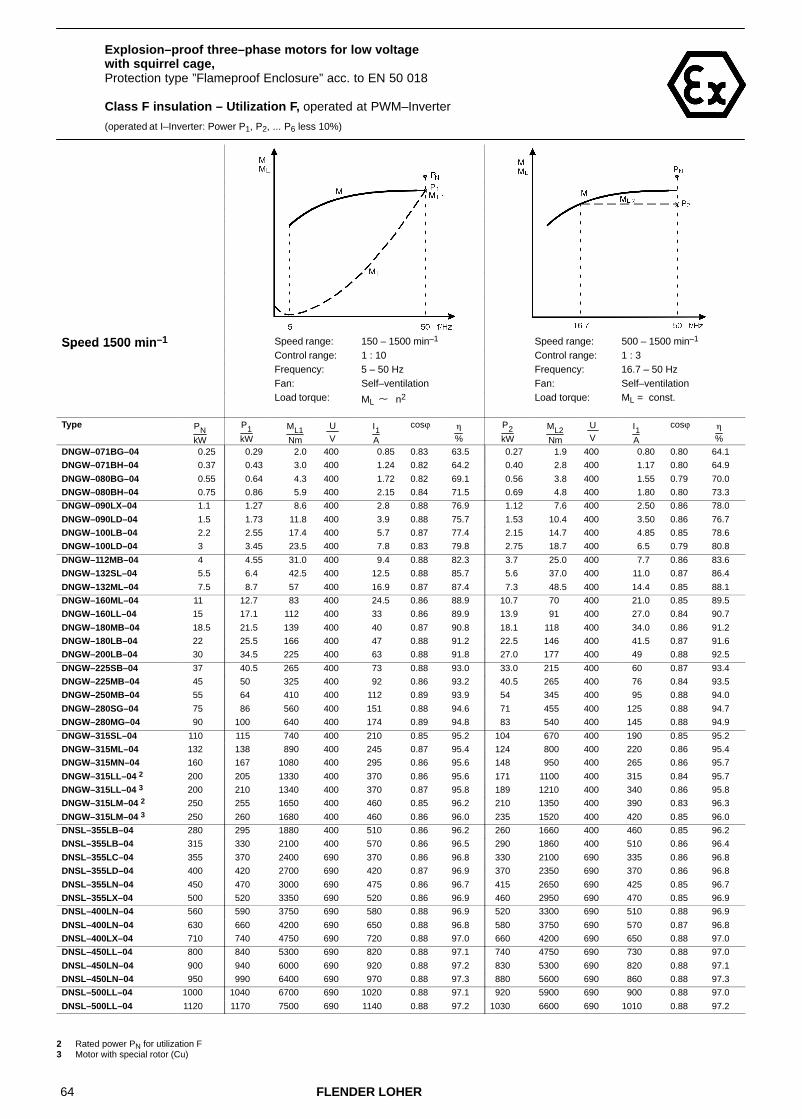
64 FLENDER LOHER
Explosion–proof three–phase motors for low voltage with squirrel cage,Protection type ”Flameproof Enclosure” acc. to EN 50 018
Class F insulation – Utilization F, operated at PWM–Inverter
(operated at I–Inverter: Power P1, P2, ... P6 less 10%)
Speed 1500 min–1 Speed range: 150 – 1500 min–1 Speed range: 500 – 1500 min–1Speed 1500 minControl range: 1 : 10 Control range: 1 : 3Frequency: 5 – 50 Hz Frequency: 16.7 – 50 HzFan: Self–ventilation Fan: Self–ventilation
Load torque: ML � n2 Load torque: ML = const.
Type PNkW
P1kW
ML1Nm
U V
I1A
cosϕ �
%
P2kW
ML2Nm
U V
I1A
cosϕ �
%
DNGW–071BG–04 0.25 0.29 2.0 400 0.85 0.83 63.5 0.27 1.9 400 0.80 0.80 64.1
DNGW–071BH–04 0.37 0.43 3.0 400 1.24 0.82 64.2 0.40 2.8 400 1.17 0.80 64.9
DNGW–080BG–04 0.55 0.64 4.3 400 1.72 0.82 69.1 0.56 3.8 400 1.55 0.79 70.0
DNGW–080BH–04 0.75 0.86 5.9 400 2.15 0.84 71.5 0.69 4.8 400 1.80 0.80 73.3
DNGW–090LX–04 1.1 1.27 8.6 400 2.8 0.88 76.9 1.12 7.6 400 2.50 0.86 78.0
DNGW–090LD–04 1.5 1.73 11.8 400 3.9 0.88 75.7 1.53 10.4 400 3.50 0.86 76.7
DNGW–100LB–04 2.2 2.55 17.4 400 5.7 0.87 77.4 2.15 14.7 400 4.85 0.85 78.6
DNGW–100LD–04 3 3.45 23.5 400 7.8 0.83 79.8 2.75 18.7 400 6.5 0.79 80.8
DNGW–112MB–04 4 4.55 31.0 400 9.4 0.88 82.3 3.7 25.0 400 7.7 0.86 83.6
DNGW–132SL–04 5.5 6.4 42.5 400 12.5 0.88 85.7 5.6 37.0 400 11.0 0.87 86.4
DNGW–132ML–04 7.5 8.7 57 400 16.9 0.87 87.4 7.3 48.5 400 14.4 0.85 88.1
DNGW–160ML–04 11 12.7 83 400 24.5 0.86 88.9 10.7 70 400 21.0 0.85 89.5
DNGW–160LL–04 15 17.1 112 400 33 0.86 89.9 13.9 91 400 27.0 0.84 90.7
DNGW–180MB–04 18.5 21.5 139 400 40 0.87 90.8 18.1 118 400 34.0 0.86 91.2
DNGW–180LB–04 22 25.5 166 400 47 0.88 91.2 22.5 146 400 41.5 0.87 91.6
DNGW–200LB–04 30 34.5 225 400 63 0.88 91.8 27.0 177 400 49 0.88 92.5
DNGW–225SB–04 37 40.5 265 400 73 0.88 93.0 33.0 215 400 60 0.87 93.4
DNGW–225MB–04 45 50 325 400 92 0.86 93.2 40.5 265 400 76 0.84 93.5
DNGW–250MB–04 55 64 410 400 112 0.89 93.9 54 345 400 95 0.88 94.0
DNGW–280SG–04 75 86 560 400 151 0.88 94.6 71 455 400 125 0.88 94.7
DNGW–280MG–04 90 100 640 400 174 0.89 94.8 83 540 400 145 0.88 94.9
DNGW–315SL–04 110 115 740 400 210 0.85 95.2 104 670 400 190 0.85 95.2
DNGW–315ML–04 132 138 890 400 245 0.87 95.4 124 800 400 220 0.86 95.4
DNGW–315MN–04 160 167 1080 400 295 0.86 95.6 148 950 400 265 0.86 95.7
DNGW–315LL–04 2 200 205 1330 400 370 0.86 95.6 171 1100 400 315 0.84 95.7
DNGW–315LL–04 3 200 210 1340 400 370 0.87 95.8 189 1210 400 340 0.86 95.8
DNGW–315LM–04 2 250 255 1650 400 460 0.85 96.2 210 1350 400 390 0.83 96.3
DNGW–315LM–04 3 250 260 1680 400 460 0.86 96.0 235 1520 400 420 0.85 96.0
DNSL–355LB–04 280 295 1880 400 510 0.86 96.2 260 1660 400 460 0.85 96.2
DNSL–355LB–04 315 330 2100 400 570 0.86 96.5 290 1860 400 510 0.86 96.4
DNSL–355LC–04 355 370 2400 690 370 0.86 96.8 330 2100 690 335 0.86 96.8
DNSL–355LD–04 400 420 2700 690 420 0.87 96.9 370 2350 690 370 0.86 96.8
DNSL–355LN–04 450 470 3000 690 475 0.86 96.7 415 2650 690 425 0.85 96.7
DNSL–355LX–04 500 520 3350 690 520 0.86 96.9 460 2950 690 470 0.85 96.9
DNSL–400LN–04 560 590 3750 690 580 0.88 96.9 520 3300 690 510 0.88 96.9
DNSL–400LN–04 630 660 4200 690 650 0.88 96.8 580 3750 690 570 0.87 96.8
DNSL–400LX–04 710 740 4750 690 720 0.88 97.0 660 4200 690 650 0.88 97.0
DNSL–450LL–04 800 840 5300 690 820 0.88 97.1 740 4750 690 730 0.88 97.0
DNSL–450LN–04 900 940 6000 690 920 0.88 97.2 830 5300 690 820 0.88 97.1
DNSL–450LN–04 950 990 6400 690 970 0.88 97.3 880 5600 690 860 0.88 97.3
DNSL–500LL–04 1000 1040 6700 690 1020 0.88 97.1 920 5900 690 900 0.88 97.0
DNSL–500LL–04 1120 1170 7500 690 1140 0.88 97.2 1030 6600 690 1010 0.88 97.2
2 Rated power PN for utilization F3 Motor with special rotor (Cu)

65FLENDER LOHER
Explosion–proof three–phase motors for low voltage with squirrel cage,Protection type ”Flameproof Enclosure” acc. to EN 50 018
Class F insulation – Utilization F, operated at PWM–Inverter
(operated at I–Inverter: Power P1, P2, ... P6 less 10%)
Speed 1500 min–1 Speed range: 300 – 1500 min–1 Speed range: 150 – 1500 min–1Speed 1500 minControl range: 1 : 5 Control range: 1 : 10Frequency: 10 – 50 Hz Frequency: 5 – 50 HzFan: Self–ventilation Fan: Self–ventilation
Load torque: ML = const. Load torque: ML = const.
Type PNkW
P3kW
ML3Nm
U V
I1A
cosϕ �
%
P4kW
ML4Nm
U V
I1A
cosϕ �
%
DNGW–071BG–04 0.25 0.21 1.4 400 0.7 0.73 63.8 0.19 1.3 400 0.68 0.71 63.2
DNGW–071BH–04 0.37 0.31 2.2 400 1.02 0.73 65.1 0.28 2 400 0.98 0.71 64.6
DNGW–080BG–04 0.55 0.46 3.2 400 1.38 0.74 69.9 0.42 2.9 400 1.33 0.71 69.6
DNGW–080BH–04 0.75 0.62 4.3 400 1.68 0.77 73.5 0.56 3.8 400 1.58 0.74 73.4
DNGW–090LX–04 1.1 0.92 6.2 400 2.1 0.83 78.6 0.85 5.7 400 2 0.81 78.6
DNGW–090LD–04 1.5 1.25 8.5 400 2.95 0.82 77.4 1.15 7.9 400 2.8 0.80 77.3
DNGW–100LB–04 2.2 1.84 12.6 400 4.3 0.82 79.0 1.69 11.6 400 4.05 0.80 78.9
DNGW–100LD–04 3 2.5 16.9 400 6.1 0.76 80.9 2.3 15.5 400 5.8 0.74 80.8
DNGW–112MB–04 4 3.35 22.5 400 7.1 0.84 83.9 3.1 21 400 6.7 0.83 84.0
DNGW–132SL–04 5.5 4.6 30.5 400 9.3 0.85 86.9 4.25 28 400 8.7 0.83 86.9
DNGW–132ML–04 7.5 6.3 41.5 400 12.7 0.83 88.4 5.8 38.5 400 12 0.82 88.4
DNGW–160ML–04 11 9.2 60 400 18.3 0.83 89.7 8.1 53 400 16.6 0.81 89.7
DNGW–160LL–04 15 12.5 82 400 24.5 0.83 90.9 11.1 73 400 22.5 0.81 91.0
DNGW–180MB–04 18.5 15.5 101 400 30 0.84 91.3 13.6 89 400 27 0.82 91.2
DNGW–180LB–04 22 18.4 120 400 35 0.85 91.9 16.2 106 400 31.5 0.83 91.9
DNGW–200LB–04 30 25 163 400 45.5 0.87 92.5 22 144 400 40.5 0.86 92.6
DNGW–225SB–04 37 32.5 210 400 59 0.87 93.4 30 194 400 55 0.87 93.5
DNGW–225MB–04 45 40 260 400 75 0.84 93.5 36.5 240 400 70 0.83 93.5
DNGW–250MB–04 55 51 330 400 91 0.88 94.0 46.5 300 400 84 0.87 93.9
DNGW–280SG–04 75 70 450 400 124 0.88 94.7 64 410 400 114 0.87 94.7
DNGW–280MG–04 90 83 540 400 145 0.88 94.9 76 490 400 134 0.88 94.8
DNGW–315SL–04 110 103 660 400 188 0.85 95.2 94 610 400 174 0.83 95.2
DNGW–315ML–04 132 123 790 400 220 0.86 95.4 113 730 400 205 0.85 95.4
DNGW–315MN–04 160 148 950 400 265 0.86 95.7 136 870 400 245 0.85 95.7
DNGW–315LL–04 2 200 170 1100 400 310 0.84 95.7 157 1010 400 290 0.83 95.6
DNGW–315LL–04 3 200 187 1200 400 335 0.86 95.8 172 1100 400 310 0.85 95.8
DNGW–315LM–04 2 250 210 1340 400 390 0.83 96.3 192 1240 400 365 0.81 96.2
DNGW–315LM–04 3 250 235 1500 400 420 0.85 96.0 215 1380 400 390 0.84 96.0
DNSL–355LB–04 280 255 1620 400 450 0.85 96.2 235 1520 400 420 0.85 96.2
DNSL–355LB–04 315 285 1820 400 500 0.85 96.4 265 1710 400 470 0.85 96.3
DNSL–355LC–04 355 320 2050 690 325 0.85 96.6 300 1930 690 305 0.85 96.7
DNSL–355LD–04 400 360 2300 690 365 0.86 96.8 340 2150 690 345 0.85 96.8
DNSL–355LN–04 450 405 2600 690 415 0.85 96.7 380 2450 690 390 0.84 96.7
DNSL–355LX–04 500 450 2900 690 460 0.85 96.9 425 2700 690 435 0.84 96.9
DNSL–400LN–04 560 510 3250 690 500 0.88 96.9 475 3050 690 470 0.87 96.8
DNSL–400LN–04 630 570 3650 690 570 0.87 96.8 530 3400 690 530 0.87 96.8
DNSL–400LX–04 710 640 4100 690 630 0.88 97.0 600 3850 690 590 0.87 97.0
DNSL–450LL–04 800 720 4600 690 710 0.87 97.0 680 4350 690 680 0.87 97.0
DNSL–450LN–04 900 810 5200 690 800 0.88 97.1 760 4900 690 750 0.87 97.1
DNSL–450LN–04 950 860 5500 690 840 0.88 97.2 800 5100 690 790 0.87 97.2
DNSL–500LL–04 1000 900 5800 690 890 0.88 97.0 850 5400 690 840 0.88 96.9
DNSL–500LL–04 1120 1010 6500 690 990 0.88 97.2 950 6100 690 930 0.88 97.1
2 Rated power PN for utilization F3 Motor with special rotor (Cu)

66 FLENDER LOHER
Explosion–proof three–phase motors for low voltage with squirrel cage,Protection type ”Flameproof Enclosure” acc. to EN 50 018
Class F insulation – Utilization F, operated at PWM–Inverter
(operated at I–Inverter: Power P1, P2, ... P6 less 10%)
Speed 1500 min–1 Speed range: 150 – 1500 min–1Speed 1500 minControl range: 1 : 10Frequency: 5 – 50 HzFan: Forced ventilation
Load torque: ML = const.
Type PNkW
P5kW
ML5Nm
U V
I1A
cosϕ �
%
DNLW–112MB–04 4 4.6 31 400 9.5 0.88 82.2
DNLW–132SL–04 5.5 6.4 42.5 400 12.5 0.88 85.7
DNLW–132ML–04 7.5 8.6 57 400 16.7 0.87 87.4
DNLW–160ML–04 11 12.7 83 400 24.5 0.86 88.9
DNLW–160LL–04 15 17.1 112 400 33 0.86 89.9
DNLW–180MB–04 18.5 21.5 139 400 40 0.87 90.8
DNLW–180LB–04 22 25.5 166 400 47 0.88 91.2
DNLW–200LB–04 30 34.5 225 400 63 0.88 91.8
DNLW–225SB–04 37 41 265 400 74 0.88 92.9
DNLW–225MB–04 45 50 325 400 92 0.86 93.2
DNLW–250MB–04 55 64 410 400 112 0.89 93.9
DNLW–280SG–04 75 87 560 400 153 0.88 94.5
DNLW–280MG–04 90 99 640 400 172 0.89 94.8
DNLW–315SL–04 110 115 740 400 210 0.85 95.2
DNLW–315ML–04 132 138 890 400 245 0.87 95.4
DNLW–315MN–04 160 167 1080 400 295 0.86 95.6
DNLW–315LL–04 2 200 205 1330 400 370 0.86 95.6
DNLW–315LL–04 3 200 210 1340 400 370 0.87 95.8
DNLW–315LM–04 2 250 255 1650 400 460 0.85 96.2
DNLW–315LM–04 3 250 260 1680 400 460 0.86 96.0
DNUL–355LB–04 280 295 1880 400 510 0.86 96.2
DNUL–355LB–04 315 330 2100 400 570 0.86 96.5
DNUL–355LC–04 355 370 2400 690 370 0.86 96.8
DNUL–355LD–04 400 420 2700 690 420 0.87 96.9
DNUL–355LN–04 450 455 2900 690 460 0.85 96.7
DNUL–355LX–04 500 510 3250 690 510 0.86 96.9
DNUL–400LN–04 560 570 3650 690 560 0.88 96.9
DNUL–400LN–04 630 640 4100 690 630 0.88 96.8
DNUL–400LX–04 710 720 4600 690 700 0.88 97.0
DNUL–450LL–04 800 810 5200 690 790 0.88 97.1
DNUL–450LN–04 900 910 5800 690 890 0.88 97.2
DNUL–450LN–04 950 960 6200 690 940 0.88 97.3
DNUL–500LL–04 1000 1010 6500 690 990 0.88 97.0
DNUL–500LL–04 1120 1130 7300 690 1100 0.88 97.2
2 Rated power PN for utilization F3 Motor with special rotor (Cu)

67FLENDER LOHER
Explosion–proof three–phase motors for low voltage with squirrel cage,Protection type ”Flameproof Enclosure” acc. to EN 50 018
Class F insulation – Utilization F, operated at PWM–Inverter
(operated at I–Inverter: Power P1, P2, ... P6 less 10%)
Speed 1500 min–1 Speed range: 1500 – 2600 min–1Speed 1500 minControl range: 10 : 17Frequency: 50 – 87 HzFan: Self–ventilation,
Forced ventilationLoad torque: ML = const./ ML � n2
Type PNkW
P6kW
ML6Nm
U V
I1A
cosϕ �
%
DNGW–071BG–04 0.25 0.4 1.6 400 1.27 0.70 69.3
DNGW–071BH–04 0.37 0.59 2.4 400 1.84 0.71 70.4
DNGW–080BG–04 0.55 0.88 3.5 400 2.5 0.72 75.1
DNGW–080BH–04 0.75 1.2 4.8 400 3.1 0.76 78.1
DNGW–090LX–04 1.1 1.76 6.9 400 4 0.83 79.9
DNGW–090LD–04 1.5 2.4 9.4 400 5.5 0.82 80.3
DNGW–100LB–04 2.2 3.5 13.9 400 7.9 0.82 81.6
DNGW–100LD–04 3 4.8 18.8 400 11.2 0.77 83.7
DNGW–112MB–04 4 6.4 25 400 13.3 0.85 84.8
DNGW–132SL–04 5.5 8.8 34 400 17.5 0.85 87.4
DNGW–132ML–04 7.5 12 46 400 23.5 0.84 89.6
DNGW–160ML–04 11 17.2 65 400 34 0.84 89.2
DNGW–160LL–04 15 23.5 89 400 45.5 0.83 92.0
DNGW–180MB–04 18.5 29 109 400 55 0.85 90.9
DNGW–180LB–04 22 34.5 130 400 65 0.85 91.7
DNGW–200LB–04 30 47 176 400 86 0.88 92.1
DNGW–225SB–04 37 54 205 400 99 0.87 92.8
DNGW–225MB–04 45 66 245 400 127 0.83 92.9
DNGW–250MB–04 55 81 300 400 147 0.87 93.0
DNGW–280SG–04 75 110 410 400 198 0.87 93.6
DNGW–280MG–04 90 126 470 400 225 0.87 93.7
DNGW–315SL–04 110 151 560 400 290 0.83 93.7
DNGW–315ML–04 132 181 670 400 335 0.85 94.3
DNGW–315MN–04 160 220 820 400 405 0.84 94.9
DNGW–315LL–04 2 200 255 950 400 485 0.82 94.4
DNGW–315LL–04 3 200 275 1020 400 510 0.84 94.5
DNGW–315LM–04 2 250 315 1180 400 610 0.80 95.7
DNGW–315LM–04 3 250 345 1270 400 640 0.83 95.1
2 Rated power PN for utilization F3 Motor with special rotor (Cu)
For mains operation the motor windings have to be Y–connected.
For inverter operation ∆–connection of the windings is required.
For the control range below 50 Hz the limit torques ML2, ML3, ML4 have to be observed (see Chapter 2.4.2.2)

68 FLENDER LOHER
Explosion–proof three–phase motors for low voltage with squirrel cage,Protection type ”Flameproof Enclosure” acc. to EN 50 018
Class F insulation – Utilization F, operated at PWM–Inverter
(operated at I–Inverter: Power P1, P2, ... P6 less 10%)
Speed 1000 min–1 Speed range: 100 – 1000 min–1 Speed range: 330 – 1000 min–1Speed 1000 minControl range: 1 : 10 Control range: 1 : 3Frequency: 5 – 50 Hz Frequency: 16.7 – 50 HzFan: Self–ventilation Fan: Self–ventilation
Load torque: ML � n2 Load torque: ML = const.
Type PNkW
P1kW
ML1Nm
U V
I1A
cosϕ �
%
P2kW
ML2Nm
U V
I1A
cosϕ �
%
DNGW–071BH–06 0.25 0.29 3.2 400 0.99 0.80 57.4 0.25 2.8 400 0.88 0.76 59.2
DNGW–080BG–06 0.37 0.43 4.6 400 1.38 0.78 61.4 0.36 4.0 400 1.23 0.74 63.1
DNGW–080BH–06 0.55 0.61 6.6 400 1.84 0.78 65.4 0.46 4.9 400 1.53 0.70 67.0
DNGW–090LX–06 0.75 0.87 9.2 400 2.35 0.82 69.6 0.70 7.4 400 1.95 0.76 72.4
DNGW–090LD–06 1.1 1.27 13.3 400 3.65 0.77 69.6 0.95 9.9 400 3.05 0.68 71.3
DNGW–100LB–06 1.5 1.73 17.6 400 4.7 0.76 73.9 1.55 15.8 400 4.35 0.74 74.2
DNGW–112MB–06 2.2 2.55 26.0 400 6.1 0.82 77.0 2.15 22.0 400 5.2 0.80 78.2
DNGW–132SL–06 3 3.45 34.5 400 7.3 0.84 84.1 3.20 32.0 400 6.8 0.83 84.5
DNGW–132ML–06 4 4.6 46 400 9.9 0.83 83.0 4.25 42.5 400 9.3 0.82 83.4
DNGW–132MN–06 5.5 6.4 64 400 13.4 0.84 84.6 5.9 59 400 12.5 0.83 85.0
DNGW–160ML–06 7.5 8.7 85 400 17.4 0.86 86.8 8.0 79 400 16.1 0.85 87.1
DNGW–160LL–06 11 12.7 124 400 25.0 0.84 88.6 11.7 115 400 23.5 0.83 88.8
DNGW–180LB–06 15 17.3 171 400 34.5 0.83 89.3 15.5 153 400 31.5 0.82 89.8
DNGW–200LB–06 18.5 21.5 210 400 42.5 0.84 88.8 18.8 186 400 36.5 0.85 89.7
DNGW–200LD–06 22 25.5 250 400 51 0.83 89.6 19.9 197 400 40 0.81 90.5
DNGW–225MB–06 30 34.5 340 400 66 0.84 91.6 29.0 285 400 56 0.83 92.0
DNGW–250MB–06 37 42.5 415 400 83 0.83 92.0 38.5 375 400 76 0.82 92.1
DNGW–280SG–06 45 51 500 400 91 0.88 93.1 42.5 410 400 77 0.87 93.4
DNGW–280MG–06 55 62 600 400 112 0.88 92.9 51 495 400 93 0.86 93.0
DNGW–315SL–06 75 78 760 400 143 0.85 94.3 71 690 400 131 0.85 94.3
DNGW–315ML–06 90 94 910 400 166 0.87 95.2 85 820 400 151 0.87 95.3
DNGW–315MM–06 110 115 1110 400 205 0.87 95.0 104 1000 400 185 0.87 95.1
DNGW–315MN–06 2 132 138 1330 400 240 0.89 95.3 117 1130 400 205 0.88 95.5
DNGW–315LL–06 160 167 1610 400 290 0.88 95.5 150 1450 400 260 0.88 95.6
DNGW–315LM–06 2 200 210 2000 400 375 0.86 95.8 176 1700 400 320 0.84 95.9
DNGW–315LM–06 3 200 210 2000 400 365 0.88 95.9 188 1810 400 325 0.88 95.9
DNSL–355MD–06 225 235 2250 400 420 0.84 96.0 210 2000 400 380 0.83 96.0
DNSL–355LB–06 250 260 2500 400 460 0.85 96.3 230 2200 400 415 0.84 96.3
DNSL–355LC–06 280 295 2800 690 300 0.86 96.3 260 2500 690 265 0.85 96.3
DNSL–355LD–06 315 330 3150 690 340 0.85 96.4 290 2800 690 300 0.83 96.4
DNSL–355LN–06 355 370 3550 690 375 0.86 96.4 330 3150 690 335 0.85 96.4
DNSL–355LN–06 400 420 4000 690 435 0.84 96.4 370 3550 690 385 0.83 96.5
DNSL–400LL–06 400 420 4000 690 435 0.84 96.5 370 3550 690 385 0.83 96.5
DNSL–400LN–06 450 470 4500 690 485 0.84 96.6 415 4000 690 430 0.83 96.6
DNSL–400LN–06 500 520 5000 690 530 0.84 96.7 460 4450 690 475 0.84 96.7
DNSL–450LL–06 560 590 5600 690 600 0.85 96.9 520 4950 690 530 0.85 96.9
DNSL–450LL–06 630 660 6300 690 670 0.85 97.0 580 5600 690 590 0.85 96.9
DNSL–450LN–06 710 740 7100 690 750 0.85 97.0 660 6300 690 670 0.85 97.0
DNSL–450LN–06 800 840 8000 690 850 0.85 97.1 740 7100 690 760 0.84 97.1
DNSL–500LL–06 900 940 9000 690 960 0.85 97.0 830 8000 690 850 0.85 97.0
DNSL–500LN–06 1000 1040 10000 690 1050 0.85 97.1 920 8900 690 940 0.85 97.0
DNSL–500LN–06 1120 1170 11200 690 1170 0.86 97.2 1030 9900 690 1030 0.86 97.2
DNSL–560LL–06 1250 1310 12500 690 1290 0.88 97.2 1160 11100 690 1140 0.88 97.2
DNSL–560LL–06 1400 1460 14000 690 1460 0.86 97.2 1290 12400 690 1300 0.86 97.2
DNSL–560LN–06 1600 1670 16000 690 1640 0.88 97.4 1480 14200 690 1450 0.88 97.4 2 Rated power PN for utilization F3 Motor with special rotor (Cu)

69FLENDER LOHER
Explosion–proof three–phase motors for low voltage with squirrel cage,Protection type ”Flameproof Enclosure” acc. to EN 50 018
Class F insulation – Utilization F, operated at PWM–Inverter
(operated at I–Inverter: Power P1, P2, ... P6 less 10%)
Speed 1000 min–1 Speed range: 200 – 1000 min–1 Speed range: 100 – 1000 min–1Speed 1000 minControl range: 1 : 5 Control range: 1 : 10Frequency: 10 – 50 Hz Frequency: 5 – 50 HzFan: Self–ventilation Fan: Self–ventilation
Load torque: ML = const. Load torque: ML = const.
Type PNkW
P3kW
ML3Nm
U V
I1A
cosϕ �
%
P4kW
ML4Nm
U V
I1A
cosϕ �
%
DNGW–071BH–06 0.25 0.21 2.3 400 0.81 0.70 59.2 0.17 1.8 400 0.75 0.65 57.4
DNGW–080BG–06 0.37 0.31 3.3 400 1.13 0.69 63.3 0.25 2.6 400 1.05 0.63 61.7
DNGW–080BH–06 0.55 0.39 4.3 400 1.44 0.65 66.5 0.38 3.9 400 1.42 0.65 66.1
DNGW–090LX–06 0.75 0.62 6.6 400 1.81 0.72 73.0 0.62 6.6 400 1.81 0.72 73.0
DNGW–090LD–06 1.1 0.84 8.7 400 2.7 0.67 72.8 0.75 7.8 400 2.60 0.63 72.3
DNGW–100LB–06 1.5 1.25 12.7 400 3.9 0.68 73.7 1.15 11.7 400 3.75 0.65 73.2
DNGW–112MB–06 2.2 1.84 18.7 400 4.6 0.77 78.6 1.69 17.2 400 4.35 0.75 78.5
DNGW–132SL–06 3 2.5 25 400 5.6 0.78 84.9 2.3 23 400 5.3 0.77 84.8
DNGW–132ML–06 4 3.35 33.5 400 7.8 0.78 83.9 3.1 31 400 7.4 0.76 83.8
DNGW–132MN–06 5.5 4.6 46 400 10.3 0.78 85.6 4.25 42.5 400 9.8 0.77 85.5
DNGW–160ML–06 7.5 6.3 62 400 13.4 0.80 87.4 5.5 54 400 12.2 0.77 87.2
DNGW–160LL–06 11 9.2 90 400 19.5 0.79 89.1 8.1 79 400 18 0.76 89.0
DNGW–180LB–06 15 12.5 124 400 26.5 0.79 90.2 11.1 109 400 24 0.76 90.2
DNGW–200LB–06 18.5 15.5 153 400 30.5 0.84 90.3 13.6 135 400 27 0.82 90.5
DNGW–200LD–06 22 18.4 182 400 37.5 0.80 90.6 16.2 160 400 34 0.79 90.7
DNGW–225MB–06 30 28 275 400 55 0.83 92.1 25.5 250 400 50 0.81 92.1
DNGW–250MB–06 37 34.5 335 400 69 0.81 92.1 31.5 305 400 64 0.80 91.9
DNGW–280SG–06 45 42 405 400 76 0.87 93.4 38 370 400 69 0.86 93.4
DNGW–280MG–06 55 51 490 400 93 0.86 93.0 46.5 450 400 86 0.85 93.0
DNGW–315SL–06 75 70 680 400 129 0.84 94.3 64 620 400 120 0.84 94.3
DNGW–315ML–06 90 84 810 400 150 0.86 95.3 77 750 400 138 0.86 95.3
DNGW–315MM–06 110 103 990 400 183 0.87 95.1 94 910 400 169 0.86 95.1
DNGW–315MN–06 2 132 116 1120 400 200 0.88 95.5 107 1030 400 187 0.88 95.5
DNGW–315LL–06 160 149 1430 400 260 0.88 95.6 136 1320 400 240 0.87 95.6
DNGW–315LM–06 2 200 176 1700 400 320 0.84 95.9 162 1560 400 300 0.83 95.9
DNGW–315LM–06 3 200 186 1800 400 325 0.88 95.9 172 1650 400 300 0.87 95.9
DNSL–355MD–06 225 205 1950 400 370 0.83 96.0 191 1830 400 350 0.82 95.9
DNSL–355LB–06 250 225 2150 400 405 0.83 96.3 210 2050 400 385 0.82 96.2
DNSL–355LC–06 280 255 2450 690 265 0.85 96.3 235 2300 690 245 0.84 96.3
DNSL–355LD–06 315 285 2750 690 300 0.83 96.4 265 2550 690 280 0.82 96.3
DNSL–355LN–06 355 320 3100 690 325 0.85 96.4 300 2900 690 310 0.84 96.4
DNSL–355LN–06 400 360 3450 690 375 0.83 96.5 340 3250 690 360 0.82 96.5
DNSL–400LL–06 400 360 3450 690 375 0.83 96.5 340 3250 690 360 0.82 96.5
DNSL–400LN–06 450 405 3900 690 425 0.83 96.6 380 3650 690 400 0.83 96.6
DNSL–400LN–06 500 450 4350 690 470 0.83 96.7 425 4050 690 445 0.83 96.7
DNSL–450LL–06 560 510 4850 690 520 0.84 96.9 475 4550 690 490 0.84 96.8
DNSL–450LL–06 630 570 5500 690 580 0.84 96.9 530 5100 690 550 0.84 96.9
DNSL–450LN–06 710 640 6200 690 650 0.85 97.0 600 5800 690 620 0.84 97.0
DNSL–450LN–06 800 720 6900 690 740 0.84 97.1 680 6500 690 700 0.83 97.1
DNSL–500LL–06 900 810 7800 690 830 0.85 97.0 760 7300 690 780 0.84 96.9
DNSL–500LN–06 1000 900 8700 690 920 0.85 97.0 850 8100 690 870 0.84 97.0
DNSL–500LN–06 1120 1010 9700 690 1010 0.86 97.2 950 9100 690 950 0.86 97.1
DNSL–560LL–06 1250 1130 10800 690 1110 0.87 97.2 1060 10200 690 1050 0.87 97.2
DNSL–560LL–06 1400 1260 12100 690 1270 0.86 97.2 1190 11400 690 1210 0.85 97.1
DNSL–560LN–06 1600 1440 13800 690 1420 0.88 97.3 1360 13000 690 1340 0.87 97.3 2 Rated power PN for utilization F3 Motor with special rotor (Cu)
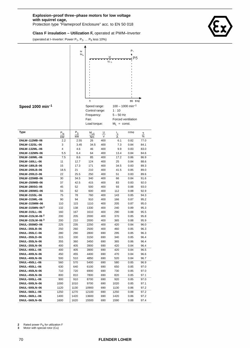
70 FLENDER LOHER
Explosion–proof three–phase motors for low voltage with squirrel cage,Protection type ”Flameproof Enclosure” acc. to EN 50 018
Class F insulation – Utilization F, operated at PWM–Inverter
(operated at I–Inverter: Power P1, P2, ... P6 less 10%)
Speed 1000 min–1 Speed range: 100 – 1000 min–1Speed 1000 minControl range: 1 : 10Frequency: 5 – 50 HzFan: Forced ventilation
Load torque: ML = const.
Type PNkW
P5kW
ML5Nm
U V
I1A
cosϕ �
%
DNLW–112MB–06 2.2 2.55 26 400 6.1 0.82 77.0
DNLW–132SL–06 3 3.45 34.5 400 7.3 0.84 84.1
DNLW–132ML–06 4 4.6 46 400 9.9 0.83 83.0
DNLW–132MN–06 5.5 6.4 64 400 13.4 0.84 84.6
DNLW–160ML–06 7.5 8.6 85 400 17.2 0.86 86.9
DNLW–160LL–06 11 12.7 124 400 25 0.84 88.6
DNLW–180LB–06 15 17.3 171 400 34.5 0.83 89.3
DNLW–200LB–06 18.5 21 210 400 41.5 0.85 89.0
DNLW–200LD–06 22 25.5 250 400 51 0.83 89.6
DNLW–225MB–06 30 34.5 340 400 66 0.84 91.6
DNLW–250MB–06 37 42.5 415 400 83 0.83 92.0
DNLW–280SG–06 45 52 500 400 93 0.88 93.0
DNLW–280MG–06 55 62 600 400 112 0.88 92.9
DNLW–315SL–06 75 78 760 400 143 0.85 94.3
DNLW–315ML–06 90 94 910 400 166 0.87 95.2
DNLW–315MM–06 110 115 1110 400 205 0.87 95.0
DNLW–315MN–06 2 132 138 1330 400 240 0.89 95.3
DNLW–315LL–06 160 167 1610 400 290 0.88 95.5
DNLW–315LM–06 2 200 205 2000 400 370 0.85 95.8
DNLW–315LM–06 3 200 210 2000 400 365 0.88 95.9
DNUL–355MD–06 225 235 2250 400 420 0.84 96.0
DNUL–355LB–06 250 260 2500 400 460 0.85 96.3
DNUL–355LC–06 280 290 2800 690 295 0.85 96.3
DNUL–355LD–06 315 330 3150 690 340 0.85 96.4
DNUL–355LN–06 355 360 3450 690 365 0.86 96.4
DNUL–355LN–06 400 405 3900 690 420 0.84 96.4
DNUL–400LL–06 400 405 3900 690 420 0.84 96.5
DNUL–400LN–06 450 455 4400 690 470 0.84 96.6
DNUL–400LN–06 500 510 4850 690 520 0.84 96.7
DNUL–450LL–06 560 570 5400 690 580 0.85 96.9
DNUL–450LL–06 630 640 6100 690 650 0.85 97.0
DNUL–450LN–06 710 720 6900 690 730 0.85 97.0
DNUL–450LN–06 800 810 7800 690 820 0.85 97.1
DNUL–500LL–06 900 910 8700 690 920 0.85 97.0
DNUL–500LN–06 1000 1010 9700 690 1020 0.85 97.1
DNUL–500LN–06 1120 1130 10900 690 1130 0.86 97.2
DNUL–560LL–06 1250 1270 12100 690 1250 0.88 97.2
DNUL–560LL–06 1400 1420 13600 690 1420 0.86 97.2
DNUL–560LN–06 1600 1620 15500 690 1590 0.88 97.4
2 Rated power PN for utilization F3 Motor with special rotor (Cu)

71FLENDER LOHER
Explosion–proof three–phase motors for low voltage with squirrel cage,Protection type ”Flameproof Enclosure” acc. to EN 50 018
Class F insulation – Utilization F, operated at PWM–Inverter
(operated at I–Inverter: Power P1, P2, ... P6 less 10%)
Speed 1000 min–1 Speed range: 1000 – 1730 min–1Speed 1000 minControl range: 10 : 17Frequency: 50 – 87 HzFan: Self–ventilation,
Forced ventilationLoad torque: ML = const./ ML � n2
Type PNkW
P6kW
ML6Nm
U V
I1A
cosϕ �
%
DNGW–071BH–06 0.25 0.4 2.5 400 1.46 0.66 65.3
DNGW–080BG–06 0.37 0.59 3.7 400 2.05 0.65 70.2
DNGW–080BH–06 0.55 0.88 5.5 400 2.75 0.68 73.2
DNGW–090LX–06 0.75 1.2 7.4 400 3.3 0.71 78.0
DNGW–090LD–06 1.1 1.76 10.6 400 5.4 0.65 77.5
DNGW–100LB–06 1.5 2.4 14.1 400 7.1 0.67 77.8
DNGW–112MB–06 2.2 3.5 20.5 400 8.6 0.77 79.6
DNGW–132SL–06 3 4.8 27.5 400 10.6 0.80 85.4
DNGW–132ML–06 4 6.4 37 400 14.3 0.78 85.9
DNGW–132MN–06 5.5 8.8 51 400 19.1 0.79 87.2
DNGW–160ML–06 7.5 11.7 67 400 24.5 0.81 88.2
DNGW–160LL–06 11 17.2 97 400 36 0.80 89.8
DNGW–180LB–06 15 23.5 134 400 48 0.79 91.5
DNGW–200LB–06 18.5 29 166 400 56 0.84 90.8
DNGW–200LD–06 22 34.5 196 400 69 0.81 91.3
DNGW–225MB–06 30 44 250 400 88 0.81 91.8
DNGW–250MB–06 37 54 305 400 112 0.80 90.2
DNGW–280SG–06 45 66 370 400 121 0.86 93.3
DNGW–280MG–06 55 78 440 400 147 0.85 92.0
DNGW–315SL–06 75 103 570 400 198 0.83 93.2
DNGW–315ML–06 90 123 690 400 225 0.85 94.9
DNGW–315MM–06 110 151 840 400 275 0.85 94.7
DNGW–315MN–06 2 132 181 1010 400 320 0.87 95.4
DNGW–315LL–06 160 220 1220 400 390 0.87 95.5
DNGW–315LM–06 2 200 260 1450 400 490 0.82 95.6
DNGW–315LM–06 3 200 275 1520 400 490 0.87 95.4
2 Rated power PN for utilization F3 Motor with special rotor (Cu)
For mains operation the motor windings have to be Y–connected.
For inverter operation ∆–connection of the windings is required.
For the control range below 50 Hz the limit torques ML2, ML3, ML4 have to be observed (see Chapter 2.4.2.2)

72 FLENDER LOHER
Explosion–proof three–phase motors for low voltage with squirrel cage,Protection type ”Flameproof Enclosure” acc. to EN 50 018
Class F insulation – Utilization F, operated at PWM–Inverter
(operated at I–Inverter: Power P1, P2, ... P6 less 10%)
Speed 750 min–1 Speed range: 75 – 750 min–1 Speed range: 250 – 750 min–1Speed 750 minControl range: 1 : 10 Control range: 1 : 3Frequency: 5 – 50 Hz Frequency: 16.7 – 50 HzFan: Self–ventilation Fan: Self–ventilation
Load torque: ML � n2 Load torque: ML = const.
Type PNkW
P1kW
ML1Nm
U V
I1A
cosϕ �
%
P2kW
ML2Nm
U V
I1A
cosϕ �
%
DNGW–071BH–08 0.12 0.10 1.6 400 0.55 0.64 49.6 0.10 1.6 400 0.55 0.64 49.6
DNGW–080BH–08 0.25 0.29 4.2 400 1.15 0.72 56.4 0.27 3.8 400 1.08 0.69 57.3DNGW–090LX–08 0.37 0.43 6.0 400 1.51 0.71 62.7 0.40 5.5 400 1.44 0.69 63.1
DNGW–090LD–08 0.55 0.64 9.0 400 2.10 0.72 66.0 0.59 8.3 400 1.96 0.70 66.9DNGW–100LB–08 0.75 0.87 11.8 400 2.55 0.74 70.2 0.80 10.9 400 2.45 0.72 70.4
DNGW–100LD–08 1.1 1.27 17.5 400 3.55 0.77 71.2 1.00 13.8 400 3.0 0.71 72.1
DNGW–112MB–08 1.5 1.73 23.5 400 4.7 0.77 73.7 1.56 21.5 400 4.3 0.74 74.5DNGW–132SL–08 2.2 2.55 34.0 400 6.3 0.76 81.4 2.35 31.5 400 5.9 0.74 81.8
DNGW–132ML–08 3 3.45 46.5 400 8.3 0.75 83.2 3.20 43 400 7.9 0.74 83.5DNGW–160ML–08 4 4.6 62 400 10.4 0.79 84.3 4.25 57 400 9.7 0.78 84.9
DNGW–160MN–08 5.5 6.4 84 400 14.6 0.77 85.9 5.9 77 400 13.7 0.75 86.2DNGW–160LL–08 7.5 8.7 115 400 19.4 0.79 85.5 8.0 106 400 18.1 0.77 85.9
DNGW–180LB–08 11 12.7 169 400 26 0.83 87.6 11.7 156 400 24.0 0.82 88.1
DNGW–200LB–08 15 17.3 230 400 37 0.80 86.8 15.5 205 400 33.5 0.79 87.8DNGW–225SB–08 18.5 21.5 285 400 45 0.81 88.4 18.8 250 400 39.5 0.80 89.1
DNGW–225MB–08 22 25.5 335 400 54 0.79 89.5 23.5 310 400 50 0.78 89.8DNGW–250MB–08 30 34.5 450 400 68 0.83 90.9 32.0 415 400 63 0.82 91.0
DNGW–280SG–08 37 42.5 550 400 83 0.82 92.0 36.0 465 400 71 0.81 92.3
DNGW–280MG–08 45 52 670 400 101 0.82 92.5 44.5 580 400 87 0.81 92.9DNGW–315SL–08 55 57 740 400 112 0.80 94.1 52 670 400 103 0.79 94.2
DNGW–315ML–08 75 78 1010 400 152 0.81 94.0 71 910 400 139 0.80 94.1DNGW–315MM–08 90 94 1210 400 180 0.82 94.6 85 1100 400 164 0.81 94.7
DNGW–315MN–08 2 110 115 1480 400 225 0.81 94.0 98 1260 400 195 0.79 94.2
DNGW–315LL–08 132 138 1780 400 265 0.81 94.4 120 1540 400 235 0.80 94.6DNGW–315LM–08 2 160 155 2000 400 300 0.81 94.9 126 1630 400 250 0.78 95.2
DNGW–315LM–08 3 160 167 2150 400 315 0.82 95.5 150 1920 400 290 0.80 95.6DNSL–355LB–08 200 210 2700 400 390 0.81 95.7 185 2350 400 350 0.79 95.7
DNSL–355LC–08 225 235 3000 690 250 0.82 95.4 210 2650 690 230 0.81 95.5DNSL–355LD–08 250 260 3350 690 280 0.82 95.6 230 2950 690 250 0.80 95.6
DNSL–355LN–08 280 295 3750 690 315 0.82 95.9 260 3350 690 280 0.81 96.0
DNSL–355LX–08 315 330 4250 690 350 0.83 95.8 290 3700 690 310 0.82 95.9DNSL–400LL–08 355 370 4750 690 395 0.82 96.1 330 4200 690 355 0.81 96.2
DNSL–400LN–08 400 420 5400 690 445 0.82 96.2 370 4750 690 395 0.81 96.2DNSL–400LX–08 450 470 6000 690 500 0.82 96.2 415 5300 690 445 0.81 96.3
DNSL–450LL–08 500 520 6700 690 540 0.84 96.5 460 5900 690 480 0.83 96.6
DNSL–450LN–08 560 590 7500 690 610 0.84 96.6 520 6600 690 540 0.83 96.6DNSL–450LN–08 630 660 8400 690 680 0.84 96.7 580 7500 690 610 0.83 96.7
DNSL–450LX–08 670 700 9000 690 730 0.83 96.8 620 7900 690 650 0.82 96.8DNSL–500LL–08 710 740 9500 690 750 0.86 96.9 660 8400 690 670 0.85 96.9
DNSL–500LL–08 800 840 10700 690 850 0.86 96.9 740 9500 690 750 0.85 97.0
DNSL–500LN–08 900 940 12100 690 970 0.84 96.7 830 10700 690 860 0.84 96.7DNSL–500LX–08 950 990 12700 690 1030 0.83 96.9 880 11200 690 920 0.83 96.9
DNSL–560LL–08 1000 1040 13400 690 1070 0.84 97.0 920 11800 690 950 0.84 97.0DNSL–560LL–08 1100 1150 14700 690 1180 0.84 97.6 1020 13000 690 1050 0.84 97.5
DNSL–560LN–08 1200 1250 16100 690 1280 0.84 97.0 1110 14200 690 1140 0.84 97.0
DNSL–560LN–08 1350 1410 18100 690 1450 0.84 97.1 1250 16000 690 1290 0.84 97.1 2 Rated power PN for utilization F3 Motor with special rotor (Cu)

73FLENDER LOHER
Explosion–proof three–phase motors for low voltage with squirrel cage,Protection type ”Flameproof Enclosure” acc. to EN 50 018
Class F insulation – Utilization F, operated at PWM–Inverter
(operated at I–Inverter: Power P1, P2, ... P6 less 10%)
Speed 750 min–1 Speed range: 250 – 750 min–1 Speed range: 75 – 750 min–1Speed 750 minControl range: 1 : 5 Control range: 1 : 10Frequency: 10 – 50 Hz Frequency: 5 – 50 HzFan: Self–ventilation Fan: Self–ventilation
Load torque: ML = const. Load torque: ML = const.
Type PNkW
P3kW
ML3Nm
U V
I1A
cosϕ �
%
P4kW
ML4Nm
U V
I1A
cosϕ �
%
DNGW–071BH–08 0.12 0.1 1.5 400 0.54 0.62 49.3 0.09 1.3 400 0.53 0.60 48.5
DNGW–080BH–08 0.25 0.21 3 400 0.98 0.61 56.9 0.18 2.6 400 0.96 0.60 56.2DNGW–090LX–08 0.37 0.31 4.3 400 1.29 0.62 62.4 0.28 4 400 1.25 0.60 61.7
DNGW–090LD–08 0.55 0.46 6.5 400 1.7 0.64 67.2 0.42 6 400 1.65 0.61 66.8DNGW–100LB–08 0.75 0.63 8.6 400 2.15 0.66 69.7 0.58 7.9 400 2.1 0.63 69.1
DNGW–100LD–08 1.1 0.88 12.1 400 2.85 0.68 71.8 0.77 10.6 400 2.7 0.64 71.0
DNGW–112MB–08 1.5 1.25 17.1 400 3.75 0.69 75.0 1.15 15.8 400 3.6 0.66 74.8DNGW–132SL–08 2.2 1.84 24.5 400 5 0.69 82.0 1.69 22.5 400 4.8 0.66 81.7
DNGW–132ML–08 3 2.5 33.5 400 6.7 0.68 83.8 2.3 31 400 6.4 0.66 83.6DNGW–160ML–08 4 3.35 44.5 400 8.1 0.73 85.9 2.95 39.5 400 7.5 0.70 86.0
DNGW–160MN–08 5.5 4.6 61 400 11.6 0.70 86.4 4.05 53 400 10.9 0.66 86.1DNGW–160LL–08 7.5 6.3 83 400 15.2 0.73 86.2 5.5 73 400 14.1 0.69 85.9
DNGW–180LB–08 11 9.2 122 400 20 0.77 88.8 8.1 108 400 18.5 0.74 88.8
DNGW–200LB–08 15 12.5 168 400 27.5 0.76 88.9 11.1 148 400 25.5 0.74 89.2DNGW–225SB–08 18.5 17.3 230 400 36.5 0.79 89.4 15.7 205 400 34 0.77 89.6
DNGW–225MB–08 22 20.5 270 400 45 0.76 90.1 18.6 245 400 42 0.74 90.1DNGW–250MB–08 30 28 365 400 56 0.81 91.2 25.5 330 400 52 0.80 91.1
DNGW–280SG–08 37 34.5 450 400 69 0.81 92.4 31.5 405 400 64 0.79 92.4
DNGW–280MG–08 45 42 540 400 83 0.81 92.9 38 495 400 77 0.79 93.0DNGW–315SL–08 55 51 660 400 102 0.79 94.2 47 610 400 95 0.78 94.2
DNGW–315ML–08 75 70 900 400 138 0.80 94.1 64 830 400 128 0.79 94.1DNGW–315MM–08 90 84 1080 400 163 0.81 94.7 77 1000 400 151 0.80 94.8
DNGW–315MN–08 2 110 96 1240 400 192 0.79 94.3 88 1130 400 179 0.78 94.3
DNGW–315LL–08 132 118 1520 400 230 0.80 94.6 107 1380 400 215 0.79 94.6DNGW–315LM–08 2 160 124 1600 400 250 0.78 95.2 113 1460 400 230 0.76 95.2
DNGW–315LM–08 3 160 148 1900 400 285 0.80 95.6 134 1730 400 265 0.78 95.6DNSL–355LB–08 200 180 2300 400 345 0.79 95.7 169 2150 400 330 0.78 95.7
DNSL–355LC–08 225 205 2600 690 225 0.80 95.5 191 2450 690 210 0.79 95.5DNSL–355LD–08 250 225 2900 690 245 0.80 95.6 210 2700 690 235 0.79 95.6
DNSL–355LN–08 280 255 3250 690 275 0.81 96.0 235 3050 690 260 0.79 96.0
DNSL–355LX–08 315 285 3650 690 305 0.81 95.9 260 3400 690 285 0.80 95.9DNSL–400LL–08 355 320 4100 690 345 0.80 96.2 300 3850 690 330 0.79 96.2
DNSL–400LN–08 400 360 4650 690 385 0.81 96.3 335 4350 690 365 0.80 96.3DNSL–400LX–08 450 405 5200 690 440 0.81 96.3 380 4900 690 415 0.80 96.3
DNSL–450LL–08 500 450 5800 690 475 0.83 96.6 425 5400 690 450 0.82 96.6
DNSL–450LN–08 560 510 6500 690 530 0.83 96.6 475 6100 690 500 0.82 96.6DNSL–450LN–08 630 570 7300 690 600 0.83 96.7 530 6800 690 560 0.82 96.7
DNSL–450LX–08 670 600 7700 690 640 0.82 96.8 570 7300 690 610 0.81 96.8DNSL–500LL–08 710 640 8200 690 660 0.84 96.9 600 7700 690 620 0.84 96.9
DNSL–500LL–08 800 720 9200 690 740 0.85 96.9 680 8700 690 700 0.84 96.9
DNSL–500LN–08 900 810 10400 690 840 0.84 96.7 760 9800 690 790 0.83 96.7DNSL–500LX–08 950 860 11000 690 900 0.82 96.9 800 10300 690 850 0.82 96.9
DNSL–560LL–08 1000 900 11500 690 930 0.84 96.9 850 10800 690 880 0.84 96.9DNSL–560LL–08 1100 990 12700 690 1020 0.84 97.5 930 11900 690 960 0.83 97.4
DNSL–560LN–08 1200 1080 13900 690 1110 0.84 97.0 1020 13000 690 1050 0.84 96.9
DNSL–560LN–08 1350 1220 15600 690 1260 0.84 97.1 1140 14600 690 1180 0.83 97.0 2 Rated power PN for utilization F3 Motor with special rotor (Cu)

74 FLENDER LOHER
Explosion–proof three–phase motors for low voltage with squirrel cage,Protection type ”Flameproof Enclosure” acc. to EN 50 018
Class F insulation – Utilization F, operated at PWM–Inverter
(operated at I–Inverter: Power P1, P2, ... P6 less 10%)
Speed 750 min–1 Speed range: 75 – 750 min–1Speed 750 minControl range: 1 : 10Frequency: 5 – 50 HzFan: Forced ventilation
Load torque: ML = const.
Type PNkW
P5kW
ML5Nm
U V
I1A
cosϕ �
%
DNLW–112MB–08 1.5 1.72 23.5 400 4.65 0.76 73.7
DNLW–132SL–08 2.2 2.55 34 400 6.3 0.76 81.4
DNLW–132ML–08 3 3.45 46.5 400 8.3 0.75 83.2
DNLW–160ML–08 4 4.6 62 400 10.4 0.79 84.3
DNLW–160MN–08 5.5 6.4 84 400 14.6 0.77 85.9
DNLW–160LL–08 7.5 8.7 115 400 19.4 0.79 85.5
DNLW–180LB–08 11 12.7 169 400 26 0.83 87.6
DNLW–200LB–08 15 17.2 230 400 37 0.80 86.8
DNLW–225SB–08 18.5 21.5 285 400 45 0.81 88.4
DNLW–225MB–08 22 25.5 335 400 54 0.79 89.5
DNLW–250MB–08 30 34.5 450 400 68 0.83 90.9
DNLW–280SG–08 37 42.5 550 400 83 0.82 92.0
DNLW–280MG–08 45 52 670 400 101 0.82 92.5
DNLW–315SL–08 55 57 740 400 112 0.80 94.1
DNLW–315ML–08 75 78 1010 400 152 0.81 94.0
DNLW–315MM–08 90 94 1210 400 180 0.82 94.6
DNLW–315MN–08 2 110 115 1480 400 225 0.81 94.0
DNLW–315LL–08 132 138 1780 400 265 0.81 94.4
DNLW–315LM–08 2 160 155 2000 400 300 0.81 94.9
DNLW–315LM–08 3 160 167 2150 400 315 0.82 95.5
DNUL–355LB–08 200 210 2700 400 390 0.81 95.7
DNUL–355LC–08 225 235 3000 690 250 0.82 95.4
DNUL–355LD–08 250 260 3350 690 280 0.82 95.6
DNUL–355LN–08 280 285 3650 690 305 0.82 95.9
DNUL–355LX–08 315 320 4100 690 340 0.82 95.8
DNUL–400LL–08 355 360 4600 690 385 0.82 96.1
DNUL–400LN–08 400 405 5200 690 430 0.82 96.2
DNUL–400LX–08 450 455 5900 690 485 0.82 96.2
DNUL–450LL–08 500 510 6500 690 530 0.84 96.5
DNUL–450LN–08 560 570 7300 690 590 0.84 96.6
DNUL–450LN–08 630 640 8200 690 660 0.84 96.7
DNUL–450LX–08 670 680 8700 690 710 0.83 96.8
DNUL–500LL–08 710 720 9200 690 730 0.85 97.0
DNUL–500LL–08 800 810 10400 690 820 0.85 96.9
DNUL–500LN–08 900 910 11700 690 940 0.84 96.7
DNUL–500LX–08 950 960 12300 690 1000 0.83 96.9
DNUL–560LL–08 1000 1010 13000 690 1040 0.84 97.0
DNUL–560LL–08 1100 1110 14300 690 1140 0.84 97.6
DNUL–560LN–08 1200 1210 15500 690 1240 0.84 97.0
DNUL–560LN–08 1350 1370 17500 690 1400 0.84 97.1
2 Rated power PN for utilization F3 Motor with special rotor (Cu)

75FLENDER LOHER
Explosion–proof three–phase motors for low voltage with squirrel cage,Protection type ”Flameproof Enclosure” acc. to EN 50 018
Class F insulation – Utilization F, operated at PWM–Inverter
(operated at I–Inverter: Power P1, P2, ... P6 less 10%)
Speed 750 min–1 Speed range: 750 – 1300 min–1Speed 750 minControl range: 10 : 17Frequency: 50 – 87 HzFan: Self–ventilation,
Forced ventilationLoad torque: ML = const./ ML � n2
Type PNkW
P6kW
ML6Nm
U V
I1A
cosϕ �
%
DNGW–071BH–08 0.12 0.19 1.7 400 1.04 0.62 49.7
DNGW–080BH–08 0.25 0.4 3.4 400 1.77 0.57 64.2
DNGW–090LX–08 0.37 0.59 4.8 400 2.35 0.61 65.5
DNGW–090LD–08 0.55 0.88 7.2 400 3.1 0.63 70.7
DNGW–100LB–08 0.75 1.2 9.5 400 3.95 0.65 73.2
DNGW–100LD–08 1.1 1.76 14 400 5.3 0.68 76.1
DNGW–112MB–08 1.5 2.4 18.9 400 6.9 0.68 79.1
DNGW–132SL–08 2.2 3.5 27 400 9.2 0.69 83.9
DNGW–132ML–08 3 4.8 37 400 12.3 0.69 86.0
DNGW–160ML–08 4 6.2 48 400 14.6 0.73 88.0
DNGW–160MN–08 5.5 8.6 65 400 21 0.70 88.3
DNGW–160LL–08 7.5 11.7 90 400 27.5 0.73 87.3
DNGW–180LB–08 11 17.2 132 400 37 0.78 89.6
DNGW–200LB–08 15 23.5 181 400 50 0.77 90.9
DNGW–225SB–08 18.5 27 205 400 58 0.76 90.4
DNGW–225MB–08 22 32.5 245 400 73 0.74 90.7
DNGW–250MB–08 30 44 330 400 92 0.79 90.0
DNGW–280SG–08 37 54 405 400 110 0.79 92.9
DNGW–280MG–08 45 66 495 400 133 0.79 93.6
DNGW–315SL–08 55 75 560 400 156 0.76 94.2
DNGW–315ML–08 75 103 770 400 210 0.77 93.7
DNGW–315MM–08 90 123 920 400 245 0.78 94.8
DNGW–315MN–08 2 110 151 1120 400 305 0.77 94.6
DNGW–315LL–08 132 181 1350 400 365 0.78 94.7
DNGW–315LM–08 2 160 210 1570 400 425 0.77 95.5
DNGW–315LM–08 3 160 220 1630 400 445 0.77 95.8
2 Rated power PN for utilization F3 Motor with special rotor (Cu)
For mains operation the motor windings have to be Y–connected.
For inverter operation ∆–connection of the windings is required.
For the control range below 50 Hz the limit torques ML2, ML3, ML4 have to be observed (see Chapter 2.4.2.2)

76 FLENDER LOHER
3.6 Six–phase motors for low voltagewith squirrel cage,Totally enclosed fan–cooled
Class F insulation – Utilization B, operated at I–Inverter
Speed 3000 min–1 Speed range: 300 – 3000 min–1 Speed range: 1000 – 3000 min–1Speed 3000 minControl range: 1 : 10 Control range: 1 : 3Frequency: 5 – 50 Hz Frequency: 16.7 – 50 HzFan: Self–ventilation Fan: Self–ventilation
Load torque: ML � n2 Load torque: ML = const.
Type PNkW
P1kW
ML1Nm
U V
I1A
cosϕ �
%
P2kW
ML2Nm
U V
I1A
cosϕ �
%
ANSA–355LC–02 355 325 1050 690 2 x 153 0.93 96.8 290 920 690 2 x 137 0.92 96.7
ANSA–355LD–02 400 385 1240 690 2 x 183 0.91 97.0 335 1070 690 2 x 161 0.90 96.9
ANSA–355LX–02 450 415 1330 690 2 x 199 0.91 96.5 360 1160 690 2 x 174 0.91 96.5
ANSA–400LN–02 500 485 1550 690 2 x 230 0.92 96.8 420 1340 690 2 x 200 0.91 96.7
ANSA–400LN–02 560 520 1660 690 2 x 245 0.92 96.9 460 1470 690 2 x 220 0.91 96.8
ANSA–400LX–02 630 580 1860 690 2 x 275 0.92 96.9 520 1660 690 2 x 245 0.92 96.9
ANSA–450LL–02 710 650 2100 690 2 x 310 0.92 96.9 590 1890 690 2 x 280 0.91 96.8
ANSA–450LN–02 800 740 2350 690 2 x 355 0.91 97.0 670 2150 690 2 x 320 0.91 96.9
ANSA–450LN–02 900 830 2650 690 2 x 395 0.91 97.2 760 2400 690 2 x 365 0.91 97.1

77FLENDER LOHER
Six–phase motors for low voltage with squirrel cage,Totally enclosed fan–cooled
Class F insulation – Utilization B, operated at I–Inverter
Speed 3000 min–1 Speed range: 600 – 3000 min–1 Speed range: 300 – 3000 min–1Speed 3000 minControl range: 1 : 5 Control range: 1 : 10Frequency: 10 – 50 Hz Frequency: 5 – 50 HzFan: Self–ventilation Fan: Self–ventilation
Load torque: ML = const. Load torque: ML = const.
Type PNkW
P3kW
ML3Nm
U V
I1A
cosϕ �
%
P4kW
ML4Nm
U V
I1A
cosϕ �
%
ANSA–355LC–02 355 275 880 690 2 x 130 0.92 96.7 255 820 690 2 x 122 0.91 96.6
ANSA–355LD–02 400 330 1060 690 2 x 159 0.90 96.9 310 1000 690 2 x 151 0.90 96.8
ANSA–355LX–02 450 340 1090 690 2 x 165 0.90 96.4 315 1010 690 2 x 154 0.90 96.4
ANSA–400LN–02 500 405 1300 690 2 x 194 0.91 96.7 375 1210 690 2 x 181 0.91 96.6
ANSA–400LN–02 560 440 1400 690 2 x 210 0.91 96.8 410 1310 690 2 x 197 0.91 96.7
ANSA–400LX–02 630 495 1580 690 2 x 235 0.91 96.8 460 1480 690 2 x 220 0.91 96.8
ANSA–450LL–02 710 570 1810 690 2 x 270 0.91 96.8 530 1700 690 2 x 255 0.91 96.7
ANSA–450LN–02 800 640 2050 690 2 x 310 0.90 96.9 600 1910 690 2 x 290 0.90 96.8
ANSA–450LN–02 900 730 2350 690 2 x 350 0.91 97.1 690 2200 690 2 x 335 0.90 97.0

78 FLENDER LOHER
Six–phase motors for low voltage with squirrel cage,Totally enclosed fan–cooled
Class F insulation – Utilization B, operated at I–Inverter
Speed 3000 min–1 Speed range: 300 – 3000 min–1Speed 3000 minControl range: 1 : 10Frequency: 5 – 50 HzFan: Forced ventilation
Load torque: ML = const.
Type PNkW
P5kW
ML5Nm
U V
I1A
cosϕ �
%
ANUA–355LC–02 355 325 1050 690 2 x 153 0.93 96.8
ANUA–355LD–02 400 380 1220 690 2 x 181 0.91 97.0
ANUA–355LX–02 450 410 1310 690 2 x 196 0.91 96.5
ANUA–400LN–02 500 455 1460 690 2 x 215 0.91 96.7
ANUA–400LN–02 560 510 1630 690 2 x 240 0.92 96.9
ANUA–400LX–02 630 570 1840 690 2 x 270 0.92 96.9
ANUA–450LL–02 710 650 2050 690 2 x 310 0.92 96.9
ANUA–450LN–02 800 730 2350 690 2 x 350 0.91 97.0
ANUA–450LN–02 900 820 2600 690 2 x 390 0.91 97.2

79FLENDER LOHER
Six–phase motors for low voltage with squirrel cage,Totally enclosed fan–cooled
Class F insulation – Utilization B, operated at I–Inverter
Speed 1500 min–1 Speed range: 150 – 1500 min–1 Speed range: 500 – 1500 min–1Speed 1500 minControl range: 1 : 10 Control range: 1 : 3Frequency: 5 – 50 Hz Frequency: 16.7 – 50 HzFan: Self–ventilation Fan: Self–ventilation
Load torque: ML � n2 Load torque: ML = const.
Type PNkW
P1kW
ML1Nm
U V
I1A
cosϕ �
%
P2kW
ML2Nm
U V
I1A
cosϕ �
%
ANSA–355LC–04 355 325 2100 690 2 x 165 0.86 96.8 300 1910 690 2 x 153 0.85 96.7
ANSA–355LD–04 400 365 2350 690 2 x 184 0.87 96.8 335 2150 690 2 x 170 0.86 96.8
ANSA–355LN–04 450 410 2650 690 2 x 210 0.85 96.7 380 2400 690 2 x 196 0.85 96.7
ANSA–355LX–04 500 460 2950 690 2 x 235 0.86 96.9 420 2700 690 2 x 215 0.85 96.9
ANSA–400LN–04 560 510 3300 690 2 x 250 0.88 96.9 470 3000 690 2 x 235 0.87 96.8
ANSA–400LN–04 630 580 3700 690 2 x 285 0.88 96.8 530 3400 690 2 x 265 0.87 96.8
ANSA–400LX–04 710 650 4150 690 2 x 320 0.88 97.0 600 3800 690 2 x 295 0.88 97.0
ANSA–450LL–04 800 730 4700 690 2 x 360 0.88 97.0 670 4300 690 2 x 335 0.87 97.0
ANSA–450LN–04 900 820 5300 690 2 x 405 0.88 97.1 760 4850 690 2 x 375 0.88 97.1
ANSA–450LN–04 950 860 5500 690 2 x 420 0.88 97.2 800 5100 690 2 x 395 0.88 97.2
ANSA–500LL–04 1000 910 5800 690 2 x 450 0.88 97.0 840 5400 690 2 x 415 0.88 96.9
ANSA–500LL–04 1120 1020 6500 690 2 x 500 0.89 97.2 940 6000 690 2 x 460 0.88 97.1

80 FLENDER LOHER
Six–phase motors for low voltage with squirrel cage,Totally enclosed fan–cooled
Class F insulation – Utilization B, operated at I–Inverter
Speed 1500 min–1 Speed range: 300 – 1500 min–1 Speed range: 150 – 1500 min–1Speed 1500 minControl range: 1 : 5 Control range: 1 : 10Frequency: 10 – 50 Hz Frequency: 5 – 50 HzFan: Self–ventilation Fan: Self–ventilation
Load torque: ML = const. Load torque: ML = const.
Type PNkW
P3kW
ML3Nm
U V
I1A
cosϕ �
%
P4kW
ML4Nm
U V
I1A
cosϕ �
%
ANSA–355LC–04 355 295 1890 690 2 x 151 0.85 96.7 275 1770 690 2 x 142 0.84 96.7
ANSA–355LD–04 400 330 2150 690 2 x 168 0.86 96.8 310 2000 690 2 x 159 0.85 96.8
ANSA–355LN–04 450 375 2400 690 2 x 194 0.84 96.7 350 2250 690 2 x 183 0.84 96.6
ANSA–355LX–04 500 415 2650 690 2 x 215 0.85 96.9 390 2500 690 2 x 205 0.84 96.8
ANSA–400LN–04 560 465 3000 690 2 x 230 0.87 96.8 435 2800 690 2 x 220 0.87 96.8
ANSA–400LN–04 630 520 3350 690 2 x 260 0.87 96.7 490 3150 690 2 x 245 0.87 96.7
ANSA–400LX–04 710 590 3750 690 2 x 295 0.88 97.0 550 3550 690 2 x 275 0.87 97.0
ANSA–450LL–04 800 660 4250 690 2 x 330 0.87 97.0 620 4000 690 2 x 310 0.87 96.9
ANSA–450LN–04 900 750 4800 690 2 x 370 0.88 97.1 700 4500 690 2 x 350 0.87 97.0
ANSA–450LN–04 950 790 5000 690 2 x 390 0.88 97.2 740 4750 690 2 x 370 0.87 97.1
ANSA–500LL–04 1000 830 5300 690 2 x 410 0.88 96.9 780 5000 690 2 x 390 0.87 96.8
ANSA–500LL–04 1120 930 5900 690 2 x 460 0.88 97.1 870 5600 690 2 x 430 0.88 97.0

81FLENDER LOHER
Six–phase motors for low voltage with squirrel cage,Totally enclosed fan–cooled
Class F insulation – Utilization B, operated at I–Inverter
Speed 1500 min–1 Speed range: 150 – 1500 min–1Speed 1500 minControl range: 1 : 10Frequency: 5 – 50 HzFan: Forced ventilation
Load torque: ML = const.
Type PNkW
P5kW
ML5Nm
U V
I1A
cosϕ �
%
ANUA–355LC–04 355 325 2100 690 2 x 165 0.86 96.8
ANUA–355LD–04 400 365 2350 690 2 x 184 0.87 96.8
ANUA–355LN–04 450 410 2600 690 2 x 210 0.85 96.7
ANUA–355LX–04 500 455 2900 690 2 x 230 0.86 96.9
ANUA–400LN–04 560 510 3250 690 2 x 250 0.88 96.9
ANUA–400LN–04 630 570 3650 690 2 x 285 0.88 96.8
ANUA–400LX–04 710 650 4150 690 2 x 320 0.88 97.0
ANUA–450LL–04 800 730 4650 690 2 x 360 0.88 97.0
ANUA–450LN–04 900 820 5200 690 2 x 405 0.88 97.1
ANUA–450LN–04 950 860 5500 690 2 x 420 0.88 97.2
ANUA–500LL–04 1000 910 5800 690 2 x 450 0.88 97.0
ANUA–500LL–04 1120 1020 6500 690 2 x 500 0.89 97.2

82 FLENDER LOHER
Six–phase motors for low voltage with squirrel cage,Totally enclosed fan–cooled
Class F insulation – Utilization B, operated at I–Inverter
Speed 1000 min–1 Speed range: 100 – 1000 min–1 Speed range: 330 – 1000 min–1Speed 1000 minControl range: 1 : 10 Control range: 1 : 3Frequency: 5 – 50 Hz Frequency: 16.7 – 50 HzFan: Self–ventilation Fan: Self–ventilation
Load torque: ML � n2 Load torque: ML = const.
Type PNkW
P1kW
ML1Nm
U V
I1A
cosϕ �
%
P2kW
ML2Nm
U V
I1A
cosϕ �
%
ANSA–355LC–06 280 260 2500 690 2 x 134 0.85 96.3 235 2250 690 2 x 122 0.84 96.3
ANSA–355LD–06 315 290 2800 690 2 x 151 0.84 96.4 265 2550 690 2 x 140 0.83 96.3
ANSA–355LN–06 355 325 3150 690 2 x 166 0.86 96.4 300 2850 690 2 x 154 0.85 96.4
ANSA–355LN–06 400 365 3500 690 2 x 191 0.84 96.5 335 3250 690 2 x 177 0.83 96.5
ANSA–400LN–06 450 435 4150 690 2 x 225 0.84 96.6 380 3650 690 2 x 200 0.83 96.6
ANSA–400LN–06 500 455 4400 690 2 x 235 0.84 96.7 420 4050 690 2 x 220 0.83 96.7
ANSA–450LL–06 560 510 4900 690 2 x 260 0.85 96.9 470 4500 690 2 x 245 0.84 96.8
ANSA–450LL–06 630 580 5500 690 2 x 295 0.85 96.9 530 5100 690 2 x 275 0.84 96.9
ANSA–450LN–06 710 650 6200 690 2 x 330 0.85 97.0 600 5700 690 2 x 310 0.85 97.0
ANSA–450LN–06 800 710 6800 690 2 x 365 0.84 97.1 670 6500 690 2 x 350 0.84 97.1
ANSA–500LL–06 900 820 7900 690 2 x 420 0.85 97.0 760 7300 690 2 x 390 0.85 96.9
ANSA–500LN–06 1000 910 8700 690 2 x 465 0.85 97.0 840 8100 690 2 x 430 0.85 97.0
ANSA–500LN–06 1120 1020 9800 690 2 x 510 0.87 97.2 940 9000 690 2 x 470 0.87 97.1
ANSA–560LL–06 1250 1140 11000 690 2 x 560 0.88 97.2 1050 10100 690 2 x 520 0.88 97.2
ANSA–560LL–06 1400 1270 12200 690 2 x 640 0.86 97.2 1180 11300 690 2 x 600 0.86 97.1
ANSA–560LN–06 1600 1460 14000 690 2 x 720 0.88 97.4 1340 12900 690 2 x 660 0.88 97.3

83FLENDER LOHER
Six–phase motors for low voltage with squirrel cage,Totally enclosed fan–cooled
Class F insulation – Utilization B, operated at I–Inverter
Speed 1000 min–1 Speed range: 200 – 1000 min–1 Speed range: 100 – 1000 min–1Speed 1000 minControl range: 1 : 5 Control range: 1 : 10Frequency: 10 – 50 Hz Frequency: 5 – 50 HzFan: Self–ventilation Fan: Self–ventilation
Load torque: ML = const. Load torque: ML = const.
Type PNkW
P3kW
ML3Nm
U V
I1A
cosϕ �
%
P4kW
ML4Nm
U V
I1A
cosϕ �
%
ANSA–355LC–06 280 230 2250 690 2 x 120 0.84 96.3 220 2100 690 2 x 116 0.84 96.2
ANSA–355LD–06 315 260 2500 690 2 x 138 0.83 96.3 245 2350 690 2 x 131 0.82 96.3
ANSA–355LN–06 355 295 2850 690 2 x 152 0.85 96.4 275 2650 690 2 x 143 0.84 96.4
ANSA–355LN–06 400 330 3200 690 2 x 175 0.83 96.5 310 2950 690 2 x 166 0.82 96.4
ANSA–400LN–06 450 375 3600 690 2 x 198 0.83 96.6 350 3400 690 2 x 186 0.82 96.5
ANSA–400LN–06 500 415 4000 690 2 x 220 0.83 96.6 390 3750 690 2 x 205 0.82 96.6
ANSA–450LL–06 560 465 4450 690 2 x 240 0.84 96.8 435 4200 690 2 x 230 0.84 96.8
ANSA–450LL–06 630 520 5000 690 2 x 270 0.84 96.9 490 4700 690 2 x 255 0.84 96.8
ANSA–450LN–06 710 590 5700 690 2 x 305 0.84 97.0 550 5300 690 2 x 285 0.84 96.9
ANSA–450LN–06 800 660 6400 690 2 x 345 0.84 97.1 620 6000 690 2 x 325 0.83 97.0
ANSA–500LL–06 900 750 7200 690 2 x 385 0.85 96.9 700 6700 690 2 x 360 0.84 96.9
ANSA–500LN–06 1000 830 8000 690 2 x 425 0.85 97.0 780 7500 690 2 x 405 0.84 96.9
ANSA–500LN–06 1120 930 8900 690 2 x 465 0.87 97.1 870 8400 690 2 x 440 0.86 97.1
ANSA–560LL–06 1250 1040 10000 690 2 x 510 0.88 97.1 980 9400 690 2 x 485 0.87 97.1
ANSA–560LL–06 1400 1160 11100 690 2 x 590 0.86 97.1 1090 10500 690 2 x 560 0.85 97.0
ANSA–560LN–06 1600 1330 12700 690 2 x 660 0.88 97.3 1250 12000 690 2 x 620 0.87 97.3

84 FLENDER LOHER
Six–phase motors for low voltage with squirrel cage,Totally enclosed fan–cooled
Class F insulation – Utilization B, operated at I–Inverter
Speed 1000 min–1 Speed range: 100 – 1000 min–1Speed 1000 minControl range: 1 : 10Frequency: 5 – 50 HzFan: Forced ventilation
Load torque: ML = const.
Type PNkW
P5kW
ML5Nm
U V
I1A
cosϕ �
%
ANUA–355LC–06 280 260 2500 690 2 x 134 0.85 96.3
ANUA–355LD–06 315 290 2800 690 2 x 151 0.84 96.4
ANUA–355LN–06 355 325 3100 690 2 x 166 0.86 96.4
ANUA–355LN–06 400 365 3500 690 2 x 191 0.84 96.5
ANUA–400LN–06 450 410 3950 690 2 x 215 0.84 96.6
ANUA–400LN–06 500 455 4400 690 2 x 235 0.84 96.7
ANUA–450LL–06 560 510 4900 690 2 x 260 0.85 96.9
ANUA–450LL–06 630 570 5500 690 2 x 290 0.85 96.9
ANUA–450LN–06 710 650 6200 690 2 x 330 0.85 97.0
ANUA–450LN–06 800 710 6800 690 2 x 365 0.84 97.1
ANUA–500LL–06 900 820 7900 690 2 x 420 0.85 97.0
ANUA–500LN–06 1000 910 8700 690 2 x 465 0.85 97.0
ANUA–500LN–06 1120 1020 9800 690 2 x 510 0.87 97.2
ANUA–560LL–06 1250 1140 10900 690 2 x 560 0.88 97.2
ANUA–560LL–06 1400 1270 12200 690 2 x 640 0.86 97.2
ANUA–560LN–06 1600 1460 14000 690 2 x 720 0.88 97.4

85FLENDER LOHER
Six–phase motors for low voltage with squirrel cage,Totally enclosed fan–cooled
Class F insulation – Utilization B, operated at I–Inverter
Speed 750 min–1 Speed range: 75 – 750 min–1 Speed range: 250 – 750 min–1Speed 750 minControl range: 1 : 10 Control range: 1 : 3Frequency: 5 – 50 Hz Frequency: 16.7 – 50 HzFan: Self–ventilation Fan: Self–ventilation
Load torque: ML � n2 Load torque: ML = const.
Type PNkW
P1kW
ML1Nm
U V
I1A
cosϕ �
%
P2kW
ML2Nm
U V
I1A
cosϕ �
%
ANSA–355LC–08 225 205 2650 690 2 x 112 0.81 95.5 187 2400 690 2 x 10⁴ 0.80 95.5
ANSA–355LD–08 250 230 2950 690 2 x 126 0.81 95.6 210 2700 690 2 x 117 0.79 95.6
ANSA–355LN–08 280 255 3300 690 2 x 138 0.81 96.0 230 2950 690 2 x 127 0.80 96.0
ANSA–355LX–08 315 290 3700 690 2 x 155 0.82 95.9 260 3350 690 2 x 141 0.81 95.9
ANSA–400LL–08 355 325 4150 690 2 x 176 0.81 96.2 295 3800 690 2 x 162 0.80 96.2
ANSA–400LN–08 400 365 4700 690 2 x 196 0.82 96.3 330 4250 690 2 x 180 0.81 96.3
ANSA–400LX–08 450 410 5300 690 2 x 220 0.82 96.3 375 4800 690 2 x 205 0.80 96.3
ANSA–450LL–08 500 455 5900 690 2 x 240 0.83 96.6 420 5400 690 2 x 225 0.83 96.6
ANSA–450LN–08 560 510 6600 690 2 x 265 0.84 96.6 470 6000 690 2 x 250 0.83 96.6
ANSA–450LN–08 630 580 7400 690 2 x 305 0.83 96.7 530 6800 690 2 x 280 0.83 96.7
ANSA–450LX–08 670 610 7900 690 2 x 320 0.83 96.8 560 7200 690 2 x 300 0.82 96.8
ANSA–500LL–08 710 650 8300 690 2 x 335 0.85 96.9 600 7600 690 2 x 310 0.84 96.9
ANSA–500LL–08 800 730 9400 690 2 x 375 0.85 97.0 670 8600 690 2 x 345 0.84 96.9
ANSA–500LN–08 900 820 10500 690 2 x 425 0.84 96.7 760 9700 690 2 x 395 0.84 96.7
ANSA–500LX–08 950 870 11200 690 2 x 455 0.83 96.9 800 10200 690 2 x 425 0.82 96.9
ANSA–560LL–08 1000 910 11700 690 2 x 470 0.85 96.9 840 10800 690 2 x 435 0.84 96.9
ANSA–560LL–08 1100 970 12500 690 2 x 500 0.84 97.5 920 11800 690 2 x 475 0.84 97.4
ANSA–560LN–08 1200 1100 14000 690 2 x 560 0.85 97.0 1010 12900 690 2 x 520 0.85 96.9
ANSA–560LN–08 1350 1230 15800 690 2 x 630 0.84 97.1 1130 14500 690 2 x 590 0.84 97.0

86 FLENDER LOHER
Six–phase motors for low voltage with squirrel cage,Totally enclosed fan–cooled
Class F insulation – Utilization B, operated at I–Inverter
Speed 750 min–1 Speed range: 250 – 750 min–1 Speed range: 75 – 750 min–1Speed 750 minControl range: 1 : 5 Control range: 1 : 10Frequency: 10 – 50 Hz Frequency: 5 – 50 HzFan: Self–ventilation Fan: Self–ventilation
Load torque: ML = const. Load torque: ML = const.
Type PNkW
P3kW
ML3Nm
U V
I1A
cosϕ �
%
P4kW
ML4Nm
U V
I1A
cosϕ �
%
ANSA–355LC–08 225 186 2400 690 2 x 10⁴ 0.80 95.5 170 2200 690 2 x 97 0.78 95.5
ANSA–355LD–08 250 210 2650 690 2 x 117 0.79 95.6 190 2450 690 2 x 10⁹ 0.78 95.6
ANSA–355LN–08 280 230 2950 690 2 x 127 0.80 96.0 210 2700 690 2 x 119 0.78 96.0
ANSA–355LX–08 315 255 3300 690 2 x 139 0.81 95.9 235 3000 690 2 x 130 0.80 95.9
ANSA–400LL–08 355 295 3800 690 2 x 162 0.80 96.2 270 3500 690 2 x 151 0.79 96.1
ANSA–400LN–08 400 330 4250 690 2 x 180 0.81 96.3 300 3900 690 2 x 167 0.79 96.2
ANSA–400LX–08 450 370 4800 690 2 x 205 0.80 96.3 340 4400 690 2 x 190 0.79 96.2
ANSA–450LL–08 500 415 5300 690 2 x 220 0.83 96.6 390 5000 690 2 x 210 0.82 96.5
ANSA–450LN–08 560 465 6000 690 2 x 245 0.83 96.6 435 5600 690 2 x 230 0.82 96.6
ANSA–450LN–08 630 520 6700 690 2 x 275 0.82 96.7 490 6300 690 2 x 265 0.82 96.7
ANSA–450LX–08 670 560 7100 690 2 x 300 0.82 96.8 520 6700 690 2 x 280 0.81 96.8
ANSA–500LL–08 710 590 7500 690 2 x 305 0.84 96.9 550 7100 690 2 x 290 0.83 96.8
ANSA–500LL–08 800 660 8500 690 2 x 340 0.84 96.9 620 8000 690 2 x 325 0.84 96.9
ANSA–500LN–08 900 750 9600 690 2 x 390 0.84 96.7 700 9000 690 2 x 365 0.84 96.7
ANSA–500LX–08 950 790 10100 690 2 x 420 0.82 96.9 740 9500 690 2 x 395 0.82 96.9
ANSA–560LL–08 1000 830 10600 690 2 x 430 0.84 96.9 780 10000 690 2 x 405 0.84 96.8
ANSA–560LL–08 1100 910 11700 690 2 x 470 0.84 97.4 860 11000 690 2 x 445 0.84 97.3
ANSA–560LN–08 1200 1000 12800 690 2 x 520 0.85 96.9 940 12000 690 2 x 485 0.84 96.9
ANSA–560LN–08 1350 1120 14300 690 2 x 580 0.84 97.0 1050 13500 690 2 x 550 0.83 97.0

87FLENDER LOHER
Six–phase motors for low voltage with squirrel cage,Totally enclosed fan–cooled
Class F insulation – Utilization B, operated at I–Inverter
Speed 750 min–1 Speed range: 75 – 750 min–1Speed 750 minControl range: 1 : 10Frequency: 5 – 50 HzFan: Forced ventilation
Load torque: ML = const.
Type PNkW
P5kW
ML5Nm
U V
I1A
cosϕ �
%
ANUA–355LC–08 225 205 2650 690 2 x 112 0.81 95.5
ANUA–355LD–08 250 230 2950 690 2 x 126 0.81 95.6
ANUA–355LN–08 280 255 3300 690 2 x 138 0.81 96.0
ANUA–355LX–08 315 285 3700 690 2 x 153 0.82 95.9
ANUA–400LL–08 355 325 4150 690 2 x 176 0.81 96.2
ANUA–400LN–08 400 365 4700 690 2 x 196 0.82 96.3
ANUA–400LX–08 450 410 5300 690 2 x 220 0.82 96.3
ANUA–450LL–08 500 455 5800 690 2 x 240 0.83 96.6
ANUA–450LN–08 560 510 6500 690 2 x 265 0.84 96.6
ANUA–450LN–08 630 570 7400 690 2 x 300 0.83 96.7
ANUA–450LX–08 670 610 7800 690 2 x 320 0.83 96.8
ANUA–500LL–08 710 650 8300 690 2 x 335 0.85 96.9
ANUA–500LL–08 800 730 9300 690 2 x 375 0.85 97.0
ANUA–500LN–08 900 820 10500 690 2 x 425 0.84 96.7
ANUA–500LX–08 950 860 11100 690 2 x 450 0.83 96.9
ANUA–560LL–08 1000 910 11600 690 2 x 470 0.85 96.9
ANUA–560LL–08 1100 970 12500 690 2 x 500 0.84 97.5
ANUA–560LN–08 1200 1090 14000 690 2 x 560 0.85 97.0
ANUA–560LN–08 1350 1230 15700 690 2 x 630 0.84 97.1

88 FLENDER LOHER
4 Information to assignment tables4.1 Motor data for other rated voltages4.2 Motor data for a different rated frequency4.3 Motor data for inverter operation
4.1 Motor data for other rated voltages
The currents indicated in the assign-ment tables of this catalogue are appli-cable for a rated voltage of 400 V or690 V. Most of the motors are also avai-lable with a modified winding for otherrated voltages, especially for 500 V. Dueto physical reasons, larger motors (fromapprox. frame size 355) are not alwaysfeasible for all rated voltages (upon re-quest, cf. Technical List IM).
For motors up to including frame size315 the motor current indicated in theassignment table can be converted toanother motor voltage as follows:
I1new =
U Rated voltage of assignment table
I1 Current of assignment table
Unew requested rated voltage
I1new Current at the requested voltage Unew
Example:For motor ANGA–250ME–04 thepower P3 = 51 kW, the rated voltage U = 400V and the current I1 = 91 A are takenfrom the assignment table for utilizationF.For a requested rated voltage of Unew =500 V a motor current of
I1new �400 V500 V
� 91 A � 73 A
is calculated for 51 kW.
Efficiency and cos ϕ will not change forthis conversion.
4.2 Motor data for a different rated frequency
The motors indicated in the assignmenttables are designed for a rated fre-quency of 50 Hz. Basically other ratedfrequencies, e.g. 60 Hz, 75 Hz or 100Hz, are also possible at a modified win-ding design. These motors can be ope-rated at higher rated powers than the 50Hz–motors.
A detailed description of the 60 Hz–mo-tor is given in the following.
4.2.1 Power increase of the 60 Hz–motor compared to the50 Hz–motor
For the rated frequency of 60 Hz andwith adequate winding a power in-crease of 12% to 20% in comparisonwith the power data is achievable (seeTable 2) of the assignment tables for the50 Hz–motors. The power increase re-fers both to the rated power PN and tothe powers P1 to P6 on the inverter. Thepower P6 is then applicable at a fre-quency of
3� � 60 Hz � 104 Hz (limit speeds ofChapter 5.6 have to be observed!).
4.2.2 Motor data of the 60 Hz–motor
Motor data of the Types A... and D... (butnot E...) for 60 Hz up to including framesize 315 can be converted approxima-tely from the data indicated in the as-signment table as follows (larger framesizes upon request):
Power P60 = Factor � P
P Power of assignment table (P1 to P6)
P60 Power at 60 Hz (factor acc. to Table 2)
Motor current: I1 60 = Factor � I1 �
I1 Motor current of assignment table(page 12 – 87)
I1 60 Motor current at 60 Hzand power P60
U1 Motor voltage of assignment table (page 12– 87)
U60 requested motor voltage at 60 Hz(factor acc. to Table 2)
Speed: n60 = 1.2 � n
n Speed of the assignment table
n60 Speed at 60 Hz
Torque: M60 =
M Torque of assignment table
M60 Torque at 60 Hz
Displacement factor cosϕ and effi-ciency remain approximately the same.
4.3 Motor data for inverter opera-tion
The values indicated in the assignmenttables are applicable for voltages andcurrents supposed to be sinusoidal. Inthe following the motor data conversionto the values applicable for inverter ope-ration is described.
4.3.1 Conversion of the motor current
Table 2: Power increase factor for a 60 Hz–winding for motor types A..A, A..K, D... (but not E...)
2–pole 4–pole 6–pole 8–pole
Frame size Factor Frame size Factor Frame size Factor Frame size Factor
63 – 180 1.263 – 250 1.2
200 – 250 1.1563 – 250 1.2
71 – 315 1.2 71 – 315 1.2
280 – 315 1.12 280 – 315 1.15
71 – 315 1.2 71 – 315 1.2
355 – 400 1.125 355 – 450 1.125 355 – 500 1.125 355 – 500 1.125
450 on request 500 1.125 560 1.125 560 1.125
UUnew
� I1
UU60
Factor1.2
�M
The determination of the inverter requi-res among others the effective value ofthe motor current ( = inverter–output cur-rent). For inverter operation the effectivevalue I of the current is due to the harmo-nic oscillations higher than its funda-mental oscillation I1. The relative funda-mental content gi depending on the in-verter type is used for the conversion ofboth values:
I1 Effective value of the fundamental current
I Effective value of the current
gi Relative fundamental content
I �I1gi

89FLENDER LOHER
4.3.2 Conversion of the motor power factor4.3.3 Motor efficiency for inverter operation4.3.4 System efficiency
For PWM–Inverters the relative funda-mental content depends on the pulsepattern, the pulse frequency, the poweron the motor used as well as on the wor-king point. For the Loher DYNAVERT® T with theLoher–motors recommended in the as-signment tables results at a maximumpower approx.gi = 0.99 with Loher DYNAVERT® T
For I–Inverters the relative fundamen-tal content of the motor current is almostindependent of the inverter manufactu-rer and also independent of the workingpoint. In practice appliesgi = 0.96 with 6–pulse
inverter output
gi = 0.99 with 12–pulseinverter output
4.3.2 Conversion of the motorpower factor
For inverter operation the power factorλ is less by the relative fundamentalcontent gi of the current than the displa-cement factor cosϕ :λ = gi � cosϕThe displacement factor depends onthe working point. Figure 10 shows thetypical behaviour (motor side) of the dis-placement factor. As it can be seen atconstant load the displacement factorpractically remains the same, whereasit decreases at a quadratically load tor-que.
4.3.3 Motor efficiency for inverteroperation
Due to the non–sinusoidal voltages andcurrents additional losses occur in themotor. At maximum power, however,there is only an insignificant decrease ofthe motor efficiency compared to theoperation with sinusoidal voltages andcurrents.
The inverter–specific losses and con-sequently the decrease of the motor effi-ciency depend on the inverter type.
4.3.3.1 Efficiency on the PWM–Inverter
For the operation of motors on PWM–In-verters a generally applicable state-ment on the efficiency decrease is notpossible due to the considerable in-fluence on the pulse frequency and themanufacturer–specific pulse pattern.
For an operation with the PWM–Inver-ters Loher DYNAVERT® T applies:Up to a power of approx. 30 kW the effi-ciency decrease is insignificant. Withan increasing power there will be a hig-her efficiency decrease. For a 200 kW–motor it is for example 0.2%–points ap-proximately.
4.3.3.2 Efficiency on the I–Inverter
On an I–Inverter the efficiency decreaseis reduced with an increasing motorpower. For 4–pole six–phase motors it is for in-stance 0.5%–points for a power of 355kW and only 0.3%–points for 1000 kW.
4.3.4 System efficiency
For the energy costs the system effi-ciency, i.e. the overall efficiency of thedrive, consisting of motor– and inverterefficiency is decisive.
The efficiencies for the PWM–InvertersLoher DYNAVERT® T and I–InvertersLoher DYNAVERT® I are hardly diffe-rent. Already at a low power of 4 kW theLoher DYNAVERT® T reaches an effi-ciency of 94%. An increasing power re-sults in higher efficiencies, e.g. up to97% at 500 kW (exact data upon re-quest).
The system efficiency ηs is calculatedas a product from motor efficiency ηMand inverter efficiency ηI:
ηs = ηM � ηI
Fig. 10: Displacement factor (motor side) for M�n2 and M=constant
M = constant
Fig. 11: General behaviour of motor efficiency ηM inverter efficiency ηI and system efficiency ηs for M=constant
Fig. 12: General behaviour of motor efficiency ηM inverter efficiency ηI and system efficiency ηs for M�n2
M = constant
Efficiency [%]
Efficiency [%]

90 FLENDER LOHER
4.4 Six–phase motors and three–phase motors for 12/24–pulse inverters
4.4 Six–phase motors and three–phase motors for 12/24–pulse inverters
From powers of approx. 250 kW six–phase motors and 12/24–pulse I–Inver-ters are also used for variable–speeddrive systems. Figure 13 shows a com-parison of the different drive solutions.The figure shows that the number of pul-ses can refer to both the mains currentand the motor. The mains–pulse num-ber (pulse number of the inverter input)is decisive for the mains current andalso for the circuit feedback.
The motor–pulse number identifies theoscillating torques occurring for inverteroperation. Fig. 13 shows that e.g. witha six–phase motor the oscillating tor-ques are essentially lower (approx. thehalf) than with a three–phase motor(see our Technical Publication No. 4:”Speed control of asynchronous machi-nes”).
For drives with a six–phase motor lessinverter–specific losses occur insidethe motor. Therefore a higher utilizationof the motors for such drives is possible.
Fig. 13: I–inverter drives with different numbers of pulses
Number ofpulsesMains / Motor
Motor
Connection
Mains current
Motor current
Rated load Rated load Rated load Rated load
Torque
No load No load No load No load
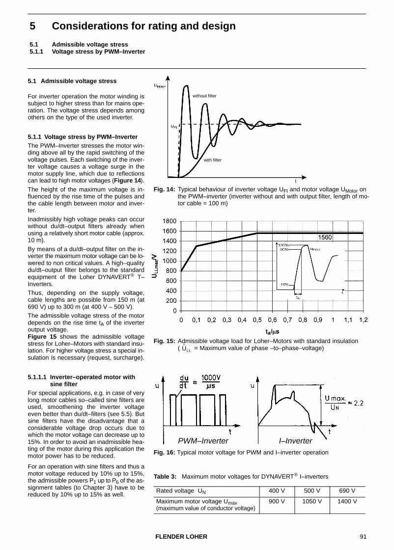
91FLENDER LOHER
5 Considerations for rating and design
5.1 Admissible voltage stress5.1.1 Voltage stress by PWM–Inverter
5.1 Admissible voltage stress
Rated voltage UN 400 V 500 V 690 V
Maximum motor voltage Umax(maximum value of conductor voltage)
900 V 1050 V 1400 V
For inverter operation the motor winding issubject to higher stress than for mains ope-ration. The voltage stress depends amongothers on the type of the used inverter.
5.1.1 Voltage stress by PWM–InverterThe PWM–Inverter stresses the motor win-ding above all by the rapid switching of thevoltage pulses. Each switching of the inver-ter voltage causes a voltage surge in themotor supply line, which due to reflectionscan lead to high motor voltages (Figure 14).
The height of the maximum voltage is in-fluenced by the rise time of the pulses andthe cable length between motor and inver-ter.
Inadmissibly high voltage peaks can occurwithout du/dt–output filters already whenusing a relatively short motor cable (approx.10 m).
By means of a du/dt–output filter on the in-verter the maximum motor voltage can be lo-wered to non critical values. A high–qualitydu/dt–output filter belongs to the standardequipment of the Loher DYNAVERT® T–Inverters.Thus, depending on the supply voltage,cable lengths are possible from 150 m (at690 V) up to 300 m (at 400 V – 500 V).The admissible voltage stress of the motordepends on the rise time tA of the inverteroutput voltage. Figure 15 shows the admissible voltagestress for Loher–Motors with standard insu-lation. For higher voltage stress a special in-sulation is necessary (request, surcharge).
5.1.1.1 Inverter–operated motor withsine filter
For special applications, e.g. in case of verylong motor cables so–called sine filters areused, smoothening the inverter voltageeven better than du/dt–filters (see 5.5). Butsine filters have the disadvantage that aconsiderable voltage drop occurs due towhich the motor voltage can decrease up to15%. In order to avoid an inadmissible hea-ting of the motor during this application themotor power has to be reduced.
For an operation with sine filters and thus amotor voltage reduced by 10% up to 15%,the admissible powers P1 up to P6 of the as-signment tables (to Chapter 3) have to bereduced by 10% up to 15% as well.
Fig. 14: Typical behaviour of inverter voltage UFI and motor voltage UMotor onthe PWM–inverter (inverter without and with output filter, length of mo-tor cable = 100 m)
without filter
with filter
Fig. 15: Admissible voltage load for Loher–Motors with standard insulation ( = Maximum value of phase –to–phase–voltage)U
^LL
PWM–Inverter I–InverterFig. 16: Typical motor voltage for PWM and I–inverter operation
Table 3: Maximum motor voltages for DYNAVERT® I–inverters

92 FLENDER LOHER
5.1.2 Voltage stress by I–Inverter5.2 Noise
5.1.2 Voltage stress by I–Inverter
I–Inverters stress the motor insulationby the occurring voltage peaks (Figure16), causing that the maximum voltageexceeds the voltage amplitude at mainsoperation. The height of the voltagepeaks depends among others on the in-verter design. Table 3 indicates the ma-ximum values of the motor voltage for anoperation with inverters of the type Lo-her DYNAVERT� I. Differences in themaximum voltage can result with inver-ters from other manufacturers.
The standard insulation system of theLoher–Motors is sufficiently designed tosuch an extent that up to rated voltagesof 690 V an operation with Loher DYNA-VERT® I–Inverters or similar inverters ispossible without restrictions. For higherrated voltages a special insulation is re-quired (upon request, surcharge).
5.2 NoiseTable 4 indicates the measuring sur-face sound–pressure level LpfA as wellas the sound–power level LWA for mo-tors without explosion protection aswell as for motors of the protection type ”Flameproof Enclosure”.
The noise values are applicable for ra-ted operation (rated power and ratedfrequency 50 Hz). The noise measure-ments are made under load in the noisetest room according to DIN EN ISO1680. The tolerance is + 3 dB(A).
For inverter operation at rated fre-quency and depending on the workingmachine, the speed range and thepower P1 to P5 a noise increase has tobe expected due to the non sinusoidalvoltages and currents. The increasedepends on the inverter type, the polenumber of the motor and the power. Ta-ble 5 indicates average values for thenoise increase at rated frequency.At decreasing frequency/speed thenoise reduces. Practical experienceshows that with high–quality invertersmany motors in partial load operation,which means reduced speed and redu-ced power, develop lower noises than inmains operation.
Figure 17 shows the typical noise be-haviour of the motors for an operationwith the PWM–Inverters Loher DYNAVERT® T and the I–Inverters Loher DYNAVERT® I. Depending on the power and the num-ber of poles results a variation range forthe decrease �L of the sound pressurelevel. The continuous and the dashedline indicated the average values.
Table 5: Average noise increase�L for inverter operationat rated frequency
Inverter type Average noiseincrease �L of the sound pressure level
DYNAVERT® T 0–3 dB(A)
DYNAVERT® I 1–3 dB(A)
Table 4: Measuring surface sound pressure level and sound power level at rated power for the Types A... and D...
LpfA Measuring surface sound pressure levelLWA Sound power levelMotors in standard design – Noise grade 1
Noise–reduced motors1 Noise grade 3Unidirectional fanFor FS 355 LN/LX up to FS 500 with inlet silencer
TypeAN / DN
Frame size
2–pole3000 min–1
LpfA
dB(A)
LWAdB(A)
4–pole1500 min–1
LpfA
dB(A)
LWAdB(A)
6–pole1000 min–1
LpfA
dB(A)
LWAdB(A)
8–pole750 min–1
LpfA
dB(A)
LWAdB(A)
2–pole3000 min–1
LpfA
dB(A)
LWAdB(A)
4–pole1500 min–1
LpfA
dB(A)
LWAdB(A)
071 52 63 46 57 45 56 42 53 – – – –
080 56 67 47 58 45 56 43 54 – – – –
090 60 72 49 60 47 58 46 57 – – – –
100 64 76 54 66 50 62 49 61 – – – –
112 64 76 54 66 54 66 53 65 55 66 – –
132 63 75 59 71 60 72 55 67 57 69 – –
160 68 80 64 76 63 75 61 73 61 73 – –
180 70 83 63 76 62 75 63 76 62 75 – –
200 73 86 63 76 60 73 64 77 63 76 – –
225 73 86 64 77 62 75 60 73 64 77 – –
250 76 90 66 80 64 78 61 75 66 80 – –
280 77 91 68 82 66 80 65 79 68 82 – –
315 80 94 70 84 70 84 69 83 70 84 – –
355 LB/LC/LD 82 97 73 88 75 90 73 88 77 92 – –
355 LN/LL/LX 78 93.5 76 91.5 74 89.5 75 90.5 74 89.5 – –
400 80 96 78 94 75 91 77 93 77 93 75 91
450 82 98.5 80 96.5 77 93.5 79 95.5 79 95.5 77 93.5
500 – – 82 99 79 96 80 97 81 98 79 96
1 Motor length (Dimension L or LC) increases for noise grade 3. Dimension drawing upon request.

93FLENDER LOHER
5.3 Overload capability5.3.1 Overload capability of the cold motor
With the infinitely variable speed con-trol it is also possible to operate the mo-tor on the resonance point of a specificmotor component (e.g. end shield orterminal box). In this case a noise in-crease of a few dB(A) exceeding theaverage noise level can occur. In mostcases a frequency change of less than1 Hz is sufficient to avoid this appearan-ce.In case of a frequency– or speed in-crease exceeding the rated frequencythe motor noise increases. Above allthe fan noise is responsible for thenoise increase in self–ventilated mo-tors. The mechanically and magneti-cally caused contents in the overallnoise are also increasing – but not tosuch an extent as the fan noise – withthe frequency. For motors with a higherfrequency range (e.g. 87 Hz–motors ormotors with field weakening) it is there-fore recommendable that forced venti-lation is used.
Figure 18 shows the average increase∆L of the measuring–surface sound–pressure level for self–ventilated mo-tors and for motors with forced ventila-tion.
5.3 Overload capability
The assignment tables indicate the tor-que values at which the motors can beoperated in continuous duty (DutyType: S1) without exceeding the admis-sible temperature limits. A momentaryoverload is admissible depending onthe base load, the duration and initialtemperature of the motor.
Note:The motor can produce a higher torqueonly when it is fed by the inverter with ahigher current. For the normal motorcontrol to a constant flux there is a li-near interconnection between torqueand current up to the 1.5fold rated tor-que approximately; i.e.: a 1.5fold ratedtorque requires the 1.5fold rated currentapproximately. Exact data on request.
By utilization of the overload capabilityit is often possible to use smaller mo-tors. In the following it is differentiatedbetween an overloading of the cold mo-tor and the overloading of the motor atoperating temperature.
5.3.1 Overload capability of thecold motor
A utilization of the overload capability ofthe cold motor is possible e.g. for star-ting of the drive. At the beginning of anoverloading the motor has the tempera-ture of the coolant (for normal condi-tions a coolant temperature � 40�C issupposed).
For motor types without explosion pro-tection applies:� In cold state (motor temperature
� 40�C) the motors can be operatedwithin the admissible control rangewith the 1.5fold rated current for10min at any frequency and speed.Following to this an operation at a re-duced torque corresponding to theassignment tables is admissible.
For EEx d–motors applies:� In cold state (motor temperature
� 40�C) the motors can be operatedwithin the admissible control rangewith the 1.5fold rated current for 60sat any frequency and speed. Following to this an operation at a re-duced torque corresponding to theassignment tables is admissible.
In case of a longer or higher overloa-ding an inquiry is necessary.
Fig. 17: Decrease ∆L of sound– pressure level in partial–loadoperation (reduced frequencyand power)
DYNAVERT® T
DYNAVERT® I
Fig. 18: Average increase ∆L of measuring–surface sound–pressure level for self–venti-lated motors and for motorswith forced ventilation at anoperation exceeding the ratedfrequency of 50 Hz
with self–ventilation
with forced ventilation 2–pole
4–pole
6–pole 8–pole
2 to 8–pole

94 FLENDER LOHER
5.3.2 Overloading of the motor at operating temperature5.3.2.1 Overload capability at constant cooling
5.3.2 Overloading of the motor atoperating temperature
The comments in this chapter are li-mited to motors without explosionprotection!
The overloading of motors at operatingtemperature is of importance e.g. forworking machines with an alternatingload. An operation at momentary over-loading is possible, when the ”thermalequilibrium” of the motor is equalized bya following low load operation and con-sequently low heat development.
Table 6 shows e.g. that for an overloa-ding of MLmax/MLmin = 2 during the dura-tion to/ts = 0.5 the thermal limit torqueonly requires the 1.58fold value of theminimum torque.
Table 6: Overload capability at constant cooling
Overload capability M / MLminto / ts 0.10 0.20 0.30 0.40 0.50 0.60 0.70 0.80 0.90
MLmax/MLmin
1.1 1.01 1.02 1.03 1.04 1.05 1.06 1.7 1.08 1.091.2 1.02 1.04 1.06 1.08 1.10 1.12 1.14 1.16 1.181.3 1.03 1.07 1.10 1.13 1.16 1.19 1.22 1.25 1.271.4 1.05 1.09 1.13 1.18 1.22 1.26 1.29 1.33 1.371.5 1.06 1.12 1.17 1.22 1.27 1.32 1.37 1.41 1.461.6 1.08 1.15 1.21 1.27 1.33 1.39 1.45 1.50 1.551.7 1.09 1.17 1.25 1.33 1.39 1.46 1.52 1.58 1.641.8 1.11 1.20 1.29 1.38 1.46 1.53 1.60 1.67 1.741.9 1.12 1.23 1.34 1.43 1.52 1.60 1.68 1.76 1.832.0 1.14 1.26 1.38 1.48 1.58 1.67 1.76 1.84 1.922.1 1.16 1.30 1.42 1.54 1.64 1.75 1.84 1.93 2.022.2 1.18 1.33 1.47 1.59 1.71 1.82 1.92 2.02 2.112.3 1.20 1.36 1.51 1.65 1.77 1.89 2.00 2.11 2.202.4 1.21 1.40 1.56 1.70 1.84 1.96 2.08 2.19 2.302.5 1.23 1.43 1.60 1.76 1.90 2.04 2.16 2.28 2.39
5.3.2.1 Overload capability at constant cooling
A constant cooling is obtained
� for forced–ventilated motors� for self–ventilated motors at
constant speed
Figure 19 shows a working cycle duringwhich the motor is loaded for the time towith MLmax over the limit torque M andis underloaded during the remainingtime of the working cycle.
Table 6 offers a help for project plan-ning of such drive systems. The tableshows depending on the relation maxi-mum torque MLmax to minimum torqueMLmin and on the relative duration of theoverloading to/ts the required thermal li-mit torque M (referred to the minimumtorque MLmin).
The following example explains the pro-cedure.
Example:The motor type has to be determined fora 4–pole forced ventilated 50 Hz–motorwith MLmin = 120 Nm, MLmax = 210 Nm,to/ts = 0.2 and a utilization to insulationClass B.For MLmax/MLmin = 210 Nm/120 Nm =1.75 the next higher value of MLmax/MLmin is chosen in the left column of Ta-ble 6. For this value and the overloadduration of to/ts = 0.2 Table 6 indicatesthe overload capability of M/MLmin =1.20. This means that for thermal rea-sons the limit torque of the motor in thisduty type only needs to exceed the mi-nimum torque by 20%:
M = 1.20 · MLmin = 1.20 · 120 Nm = 144 Nm
In accordance with the assignmenttable the motor ANLA–180LB–04 withPN = 22 kW is sufficient for this limittorque.
The relation maximum torque to ratedtorque of MLmax/MN = 210/143 = 1.47remains below the critical value ofMLmax/MN = 1.5.
With
MN � 9550PN�kW
nN�min1Nm
Therefore the motor is suitable.If the motor were chosen only depen-ding on the occurring maximum torqueof MLmax = 210 Nm, this would result inthe two types larger motorANLA–225SE–04. This proves that theutilization of the overload capability re-sults in a smaller motor type (possiblyalso in a smaller inverter) and thus in lo-wer costs.
A simplified conversion process for theoverload capability is described below.
This requires the compliance with twoconditions:
1. The maximum torque must not reachthe breakdown torque of the motortoo closely. In the following it is provi-ded that the relation maximum torqueMmax to rated torque MN is limited toMmax / MN � 1.5.
2. A periodic working cycle of max.10min duration is required: ts � 10min.
The conversion process differentiatesan overloading at constant cooling andan overloading at a varying cooling.
Fig. 19: Overload capability at con-stant cooling
Limit torque and load torque versus time
� 9550 221465
Nm � 143 Nm

95FLENDER LOHER
5.3.2.2 Overload capability of self–ventilated motors at constant load torque
5.3.2.2 Overload capability of self–ventilated motors atconstant load torque
For motors with self–ventilation thecooling effect changes with the fre-quency and the speed respectively.This has to be considered for the deter-mination of the overload capability
The procedure for a constant load tor-que is explained in the following.Figure 20 shows that at a low speed themotor is overloaded for the duration to,whereas for the remaining time of theworking cycle ts it is underloaded at thehigh speedFor the overload capability the limit tor-que of the motor at high (h) and low (l)speed is important.
For the limit torque at high speed e.g.Mh = M1 (M1 in the assignment table)has to be applied and for Ml dependingon the control range:
Control range Ml
1:3 Ml = ML2
1:5 Ml = ML3
1:10 Ml = ML4
The following example shows how todetermine the overload capability bymeans of Table 7.
Example:
With Mh/M1 = ML1/ML4 = 98 Nm / 66 Nm= 1.48 �1.5 and to/ts = 0.3 it will befound in Table 7: ML/Ml = 1.37.
This means that for this duty type themotor is allowed to exceed its limit tor-que of Ml = ML4 = 66 Nm momentarily by37% at low speed.
In the second step it is tried to make itwith a smaller motor.Motor ANGA–160MB–04 is chosenwith PN = 11 kW, as well as ML1 = 75 Nmand ML4 = 48.5 Nm. (Power and limit tor-ques are lower by approx. 25% compa-red to the previous type).
For the smaller motor results with Mh/M1 = 1.55 acc. to Table 7: ML/Ml = 1.41. This means that at a low speed thesmaller motor can be overloaded by41%. In this duty type the motor can the-refore be subject to a constant load tor-que of ML = 1.41 · 48.5 Nm = 68 Nm.Since this value is over the requestedvalue of 55 Nm, the motor is sufficientlydimensioned.
Overload capability ML / Ml
to / ts 0.10 0.20 0.30 0.40 0.50 0.60 0.70 0.80 0.90Mh/Ml
1.05 1.05 1.04 1.04 1.03 1.03 1.02 1.02 1.01 1.011.10 1.09 1.08 1.07 1.06 1.05 1.04 1.03 1.02 1.011.15 1.14 1.12 1.11 1.09 1.08 1.06 1.05 1.03 1.021.20 1.18 1.16 1.14 1.12 1.10 1.08 1.06 1.04 1.021.25 1.23 1.20 1.18 1.16 1.13 1.11 1.08 1.05 1.031.30 1.27 1.25 1.22 1.19 1.16 1.13 1.10 1.07 1.031.35 1.32 1.29 1.26 1.22 1.19 1.15 1.12 1.08 1.041.40 1.37 1.33 1.29 1.26 1.22 1.18 1.13 1.09 1.051.45 1.41 1.37 1.33 1.29 1.25 1.20 1.15 1.10 1.051.50 1.46 1.41 1.37 1.32 1.27 1.22 1.17 1.12 1.061.55 1.50 1.46 1.41 1.36 1.30 1.25 1.19 1.13 1.071.60 1.55 1.50 1.45 1.39 1.33 1.27 1.21 1.15 1.081.65 1.60 1.54 1.49 1.43 1.36 1.30 1.23 1.16 1.081.70 1.64 1.58 1.52 1.46 1.39 1.33 1.25 1.17 1.091.75 1.69 1.63 1.56 1.50 1.43 1.35 1.27 1.19 1.101.80 1.74 1.67 1.60 1.53 1.46 1.38 1.29 1.20 1.111.85 1.78 1.71 1.64 1.57 1.49 1.40 1.31 1.22 1.111.90 1.83 1.76 1.68 1.60 1.52 1.43 1.34 1.23 1.121.95 1.88 1.80 1.72 1.64 1.55 1.46 1.36 1.25 1.132.00 1.92 1.84 1.76 1.67 1.58 1.48 1.38 1.26 1.14
For a drive system with a constant loadtorque ML = 55 Nm, control range 1:10,Utilization B and the working cycle to/ts = 0.3 (ts<10min) the smallest suita-ble 4–pole motor has to be determined.
First a motor without utilization of theoverload capability is chosen in the as-signment tables.
In this case it is the motor typeANGA–160LB–04 with PN = 15 kW. Atlow speed this motor has the limit torqueMl = ML4 = 66 Nm and at a high speedthe limit torque Mh = ML1 = 98 Nm.
Table 7: Overload capability at variable cooling and constant load torque
Fig. 20: Overload capability for variable cooling and constant load torque
Limit torque and load torque Limit torque and load torqueversus frequency versus time

96 FLENDER LOHER
5.4 Inverter operation of explosion–proof motors5.5 Shaft voltages and bearing currents
5.4 Inverter operation of explosion–proof motors
Explosion–proof motors can be opera-ted at inverters when the compliance ofthe explosion protection is ensured. Forthis reason it is required as follows:
� the inverters have to be installed out-side the hazardous area
� the admissible maximum voltages onthe terminal boxes must be kept (seeChapter 5.4.4)
� the limit speeds must not be excee-ded (see Chapter 5.6)
� for motors of the protection typesEEx d, EEx e, EEx n the regulationsindicated in the Chapters 5.4.1 to5.4.3 are additionally applicable
5.4.1 Motors in ignition protectionEEx d: ”Flameproof Enclosure” acc. to EN 50018
The EEx d–motors of this catalogue areallowed to be used in the hazardousareas of Zone 1 and Zone 2.
For inverter operation these motorshave to be equipped with a thermal mo-tor protection (TMS, see 5.8) as soleprotection1. For EEx d–motors in thetemperature classes T1 to T4 globalcertificates of conformity are availablewhich are also including the inverteroperation. The motors can be operatedat the inverter up to the maximum fre-quency and maximum voltage stampedon the motor rating plate, if sole protec-tion at inverter operation is ensured.Since no special tests are required, noadditional costs will incur.
5.4.2 Motors in ignition protectionEEx e: ”Increased Safety”acc. to EN 50019
The EEx e–motors are allowed to beused in the hazardous areas of Zone 1and Zone 2.
The motors have to be equipped with athermal motor protection (TMS) as soleprotection1. In order to ensure theexplosion protection the EEx e–motorsmust be tested and certified togetherwith the respective inverter. The inver-ter parameters (e.g. voltage–frequencycharacteristic) set for the test are not al-lowed to be changed any more (test ex-penditure, extra costs).
5.4.3 Motors in ignition protectionEEx n: ”Non–sparking” or”Non–sparking electricalequipment” acc. to EN 50021
The EEx n–motors are allowed to beused in the hazardous area of Zone 2.The motors have to be equipped with athermal motor protection (TMS) as soleprotection1. Like the EEx e–motors, themotors in ignition protection EEx n mustbe tested and certified together with therespective inverter in order to ensurethe explosion protection. The inverterparameters (e.g. voltage–frequencycharacteristic) set for the test are not al-lowed to be changed any more.
The test expenditure for EEx n–motorstogether with Loher DYNAVERT®–In-verters might possibly be lower than forthe EEx e–motors (test expenditure, ex-tra costs).
The power outputs and torques achie-vable for inverter operation correspondin Temperature Class 3 with those of theA–Motors. Therefore the assignment tables fromPage 12 – 43 can be used for motors inignition protection EEx nA II T3. 2
5.4.4 Terminal boxes
On the terminal boxes of explosion–proof Loher motors (EEx d, EEx e,EEx n) for rated voltages up to 690 Vmomentary voltage peaks of 1866 V areadmissible. This value is clearly overthe admissible voltage for the insulation(see Fig. 15).
When the maximum admissible voltageof the insulation is observed, the admis-sible voltage on the terminal box willalso be kept.
For an operation with PWM–Inverterscare must be taken that the voltagepeaks caused by the reflections of thevoltage surges are not exceeding theadmissible values (see Chapter 5.1.1).
For an operation with I–Inverters thecommutation voltage peak has to beobserved (see Chapter 5.1.2).
5.5 Shaft voltages and bearing currents
It is known about mains–operated mo-tors that due to the magnetic asymme-tries a voltage is produced along themechanical shaft. The grease film of theantifriction bearings has an insulatingeffect, so that low shaft voltages cannotyet cause any currents. If, however, theshaft voltage exceeds a limit value thegrease film is punctured. A circulating
current flows through the shaft, the bea-rings and the stator frame, which mightcause a destruction of the bearings.
This phenomenon occurs only in largermotors from approx. frame size 355. Inorder to avoid bearing damages onebearing will then be insulated.
For the operation with PWM–Invertersadditional bearing currents can occur.These are mostly caused by the steepvoltage rises which occur at switching.Without inverter output filter voltage va-riations of more than 10 kV/µs can oc-cur at the winding terminals.
In order to avoid damaging bearing cur-rents the following measures are re-commended for inverters, electricalmachines and for the whole system:
Inverter:
� Reduction of the voltage rises. Non–critical values can be achieved with adu/dt–filter at the inverter output, e.g.du/dt < 0.5 kV/µs.
� For very long motor cables (> 300 m)a sine filter can be required (see5.1.1.1).
� Selection of a moderate pulse fre-quency (depending on the powersome kHz).
� Selection of a pulse pattern with lowcommon mode voltage.
� Simultaneous switchovers are to beavoided.
Electrical machine:� For machines from frame size 315
the non–drive end bearing will be in-sulated by the insulation of the bea-ring seat on the motor shaft or byusing electrically insulated antifric-tion bearings. When a tachometer isinstalled the insulation must not beshort–circuited by it. Insulation is per-haps also required for the tachome-ter.
� Use of an insulating coupling to avoidcurrents through the working ma-chine.
� Use of a rotor earth brush, if necessary.
System:
� Shielded cable between inverter andmachine (placed on both sides)
� Reliable earthing of motor, inverterand working machine.
1 For motors from frame size 280 a TMS–sole protection is perhaps only possible for inverter operation (see 5.8). These motors must be especially identified for inverter operation. The motors can also be protected by a comparable protective device, which can be totally or partially a component of the inverter.2 Observe the limit speeds acc. to the Tables 8 to 10, Page 97! Higher speeds on request.

97FLENDER LOHER
5.6 Mechanical limit speeds
5.6 Mechanical limit speedsFor an operation over the rated fre-quency it must be observed that the ma-ximum speeds are limited by the limitvalues of the antifriction bearings, thecritical rotor speed and the strength of
the rotating parts. In accordance withEN 50014 for motors used in the hazar-dous area of Zone 1 or 2, the circumfe-rential speed is also limited and conse-quently the speed of plastic fans.
For three–phase motors without explo-sion protection and for motors in protec-tion type EEx n the limit speeds indica-ted in Table 8 are applicable, for motorsin protection type EEx d the limit speedsaccording to Table 9.
Table 8: Mechanical limit speeds for motors without explosion protection (Types A..A)and motors in protection type ”n” (Types A..K) for the frame sizes 90 to 500
Num-ber ofpoles
FS 90 100 112 132 160 180 200 225 250 280 315 355LBLCLD
355LNLX
400LLLNLX
450LLLNLX
500LLLNLX
2 n/min–1 6000 6000 6000 6000 6000 6000 5200 5200 4800 4200 4000 4000 3200 3000 3000 ––2
f/Hz 100 100 100 100 100 100 87 87 80 70 66 66 53 50 50 ––
4 n/min–1 4500 4500 4500 4500 4500 4500 4500 4500 4500 4200 3700 3200 2400 2250 2100 18004
f/Hz 150 150 150 150 150 150 150 150 150 140 123 106 80 75 70 60
6 n/min–1 4000 4000 4000 4000 4000 4000 4000 4000 4000 4000 3700 3200 2400 2200 2100 18006
f/Hz 200 200 200 200 200 200 200 200 200 200 185 160 120 110 105 90
8 n/min–1 3000 3000 3000 3000 3000 3000 3000 3000 3000 3000 3000 3000 2400 2100 2100 18008
f/Hz 200 200 200 200 200 200 200 200 200 200 200 200 160 140 140 120
The motors in protection type ”n” require at the speeds indicated on the right of the stepped line the use of metal fans, if the operating speed exceeds the value according to table 10 (surcharge).
Table 9: Mechanical limit speeds for EEx d–motors of the frame sizes 71 to 500
Num-ber ofpoles
FS 71 80 90 100 112 132 160 180 200 225 250 280 315 355LBLCLD
355LNLX
400LLLNLX
450LLLNLX
500LLLNLX
2 n/min–1 6000 6000 6000 6000 6000 6000 6000 5800 5200 4600 4600 4000 4000 3600 3600 3000 3000 ––2
f/Hz 100 100 100 100 100 100 100 96 87 76 76 66 66 60 60 50 50 ––
4 n/min–1 4500 4500 4500 4500 4500 4500 4500 4500 4500 4500 4500 3800 3700 2700 2700 2250 2100 18004
f/Hz 150 150 150 150 150 150 150 150 150 150 150 126 123 90 90 75 70 60
6 n/min–1 4000 4000 4000 4000 4000 4000 4000 4000 4000 4000 4000 3800 3700 2600 2600 2200 2100 18006
f/Hz 200 200 200 200 200 200 200 200 200 200 200 190 185 130 130 110 105 90
8 n/min–1 3000 3000 3000 3000 3000 3000 3000 3000 3000 3000 3000 3000 3000 2550 2550 2100 2100 18008
f/Hz 200 200 200 200 200 200 200 200 200 200 200 200 200 170 170 140 140 120
For speeds indicated on the right of the stepped line metal fans have to be used, if the operating speed exceeds the value according to table 10 (surcharge).
Table 10: Limit speeds for plastic fansin case of protection type ”n” and ”EEx d IIC”
Num-ber ofpoles
FS 100 112 132 160 180 200 225 250 280 315
2 n/min–1 5450 5450 5610 5020 3970 4590 3970 3820 3600 36002
f/Hz 91 91 94 84 66 77 66 64 60 60
4 n/min–1 5450 5450 4650 3910 3530 3000 3000 3820 2580 ––4
f/Hz 182 182 155 130 118 100 100 127 86 ––
6 n/min–1 5450 5450 4650 3910 3530 3000 3000 2580 2290 ––6
f/Hz 273 273 233 196 177 150 150 129 115 ––
8 n/min–1 5450 5450 4650 3910 3530 3000 3000 2580 2290 ––8
f/Hz 362 362 310 260 235 200 200 172 153 ––
Motors for inverter operation with higher speeds than indicated in Table 8 and 9 are available on request (surcharge).

98 FLENDER LOHER
5.7 Relubrication intervals, grease life, grease quantities
Table 11: Grease life, grease quantities and relubrication intervals for motorswithout explosion protection (A..A) and protection type ”n” (A..K)
Grease life with permanent lubrication or relubrication interval with regreasing device
in service hours at rated speed
Grease quantity in grammes per bearing forPerma– Re–Frame size Horizontal mounting (B) Vertical mounting (V)
forPerma– Re– nent lubri– lubri– cation3000
min–11500
min–1 <=1000min–1
3000min–1
1500min–1
<=1000min–1
nent lubri– lubri– cation cation
90 24000 11 ––
100 33000 33000 15 ––
112 25 ––
132 50 ––
160 24000 17000 70 ––
180 40000 40000 33000 80 ––
200 24000 60 ––
225 20000 70 ––
250 13000 90 ––
280 120 ––
315 4000 –– –– 2800 –– –– –– 35
315 –– 8000 11000 –– 5600 8000 –– 25
355 LB/LC/LD 4000 –– –– 2800 –– –– –– 35
355 LB/LC/LD –– 8000 11000 –– 4000 5600 –– 50
355 LL/LN/LX 4000 –– –– 2000 –– –– –– 35
355 LL/LN/LX –– 8000 11000 –– 2800 4000 –– 50
400 4000 –– –– 2000 –– –– –– 35
400 –– 5600 8000 –– 2000 4000 –– 60
450 4000 –– –– 2000 –– –– –– DE:40, NDE:35
450 –– 5600 8000 –– 2000 2800 –– 70
500 –– 5600 8000 –– 2000 2800 –– 80
Table 12: Grease life, grease quantities and relubrication intervals for motorsin protection type ”EEx d IIC” (D...)
Grease life with permanent lubrication or relubrication interval with regreasing device
in service hours at rated speed
Grease quantity in grammes per bearing forPerma– Re–Frame size Horizontal mounting (B) Vertical mounting (V) forPerma– Re– nent lubri–
3000min–1
1500min–1
<=1000min–1
3000min–1
1500min–1
<=1000min–1
nent lubri– lubri– cation cation
71 5 ––
80 9 ––
90 33000 24000
33000 11 ––
100 15 ––
112 25 ––
132 40000 40000 17000 33000 50 ––
160 24000 80 ––
180 24000 100 ––
200 130 ––
225 20000 13000 190 ––
250 –– –– –– –– 190 ––
250 –– 40000 40000 ––– 24000 33000 260 ––
280 20000 –– –– 13000 –– –– 260 ––
280 –– 40000 40000 –– 24000 33000 310 ––
315 4000 –– –– 2800 –– –– –– 35
315 –– 8000 11000 –– 5600 8000 –– 25
355 LB/LC/LD 4000 –– –– 2800 –– –– –– 35
355 LB/LC/LD –– 8000 11000 –– 4000 5600 –– 50
355 LL/LN/LX 4000 –– –– 2000 –– –– –– 35
355 LL/LN/LX –– 8000 11000 –– 2800 4000 –– 50
400 4000 –– –– 2000 –– –– –– 35
400 –– 5600 8000 –– 2000 4000 –– 60
450 4000 –– –– 2000 –– –– –– DE:40, NDE:35
450 –– 5600 8000 –– 2000 2800 –– 70
500 –– 5600 8000 –– 2000 2800 –– 80
5.7 Relubrication intervals, grease life, grease quantities
Loher–Motors up to frame size 280have permanent lubrication. Accor-ding to experience the filled–in greasewill be sufficient for several years.
From frame size 315 (upon requestalso the frame sizes 160 to 280) themotors will be equipped with a regrea-sing device and a grease regulation.
The relubrication intervals for an ope-ration at the rated speed are indicatedin the Tables 11 and 12.
At speeds which are higher than the ra-ted speed, the grease life and the relu-brication intervals tf are reduced. Withreference to the corresponding timetf 50 at 50 Hz results the reduction indi-cated in Table 13.
Table 13: Reduction of grease life orrelubrication intervals
f / Hz 60 70 80 90 100
tf / tf50 0.75 0.65 0.55 0.50 0.45

99FLENDER LOHER
5.8 Motor protection5.9 Electromagnetic compatibility (EMC)
5.8 Motor protection
If a monitoring of the motor temperatureis requested, a thermal motor protec-tion (TMS) is recommendable
For motors up to approx. frame size 280the sole protection is also possible withTMS.
For motors beyond frame size 280 ap-proximately, a sole protection is oftenonly possible in connection with the in-verter. In this case the inverter limits the
maximum possible motor current.For EEx e– and EEx n–motors the rela-ting correspondence has to be certified.
It is not recommendable to protect themotors by means of commercial motor–circuit switches.
TMS = Thermal motor protection: Temperature of stator winding is monitored by PTC–thermistors
Sole protection = The TMS protects both the stator winding and the squirrel cage against inadmissible heating. This sole protection is applicable for mains– as well as inverter–operated motors.
5.9 Electromagnetic compatibility(EMC)
EMC describes the electromagnetic be-haviour of electric devices or installa-tions with respect to the
� Emission of interference
� Immunity to interference
5.9.1 EMC–Directive
The target of the EMC–Directive89/336/EEC and the German EMC–Law is that all electrical devices arefunctioning together and next to eachother without disturbance.
The EC–Certificate of Conformity con-firms the compliance with the EMC–Di-rective and the EMC–Law.
As defined by EMC an electric drive sy-stem with e.g. asynchronous motors,inverters, cables, control systems andmonitoring equipment can only be con-sidered as an entity. An EC–Certificateof Conformity for a single component,e.g. for the asynchronous machine, isonly significant to a certain extent. Inaccordance with the EMC–Law it is notrequired either, if the components – asusual for industrial drives – are only de-livered to competent specialists for theinstallation into machines and equip-ments.
The European Harmonized Standards(EN) will be applicable to assess theemitted interference and the immunityto interference of asynchronous machi-nes. The following chapters describethe EMC–behaviour of mains–operatedand inverter–operated Loher–Asyn-chronous Machines as well as of addi-tional equipment.
5.9.1.1 Mains–operated asynchronous machines
Emitted interference:The asynchronous machines meet thelimit values of Class B to EN 55011 andas to the emitted interference they cantherefore be used without special mea-sures both in an industrial and residen-tial/industrial environment (corres-ponds with EN 50081 Part 1 and Part 2).
Tests according to DIN EN 60034–1 Chapter 12 are not required.
Immunity to interference:Mains–operated three–phase asyn-chronous machines are insensitive tohigh frequencies which can be bothline–specific and radiation–specific.
As regards the interference immunity tolow–frequency mains voltage harmo-nics (mains distortion) the requirementsacc. to EN 60034–1 Chapter 12 have tobe met, i.e. the voltage harmonic factorHVF must not exceed the value 0.03.
The voltage harmonic factor HVF is de-fined as follows:
HVF � �u2
nn
�with
un = harmonic voltage referred to the rated voltage
n = order of harmonic
5.9.1.2 Inverter–operated asyn-chronous machines
Emitted interference:The EMC–behaviour depends on thesystem ”inverter–cable–asynchronousmachine”. Therefore no generally appli-cable statement is possible.
The terminal boxes of Loher–Asynchro-nous machines offer the possibility of
EMC–adequate cable entries.The installation instructions of the in-verter manufacturers have to be obser-ved.
Immunity to interference:For inverter–operated asynchronousmachines the harmonic content of thepower supply system depends on theinverter. This has to be considered forthe assignment and dimensioning ofthe asynchronous machine. The in-structions of the inverter manufacturersas well as the instructions in DIN IEC/TS 60034–17: “Cage inductionmotors when fed from Converters–Ap-plication guide” have to be considered.
5.9.1.3 Additional equipment
This refers especially to winding tempe-rature sensors PT 100, PTC thermi-stors, machine heaters, tachometers,oscillation monitoring devices and thelike.
Independently functionable components:Components which are independentlyfunctionable (e.g. oscillation monitoringsystems) have to be used in accor-dance with the correspondingly appli-cable regulations. Proofs can be madeavailable upon request.
Not independently functionablecomponents:Components which are not indepen-dently functionable must be speciallyconsidered together with the additionalequipment (e.g. evaluators) requiredfor its function and under considerationof the manufacturer data.

100 FLENDER LOHER
6 Motors for high speeds
Motors for high speeds are based onthe totally enclosed fan–cooled stan-dard motors. With adequate modifica-tions higher speeds can be achievedthan for the standard motors. Theachievable speeds and power outputsare indicated in Figure 21.
Fig. 21: Power–speed–limit of motors for high speeds