Embed Size (px)
Citation preview

TECHNICAL INSTRUCTIONS
FOR
SAFETY RECALL FLE
PRE-COLLISION SYSTEM
CERTAIN 2013 –2015 MODEL YEAR ES350 AND ES300H
The repair quality of covered vehicles is extremely important to Lexus. All dealership technicians performing this repair are required to successfully complete the most current version of the E-Learning course “Safety Recall and Service Campaign Essentials”. To ensure that all vehicles have the repair performed correctly; technicians performing this repair must successfully complete E-Learning LSCFLE AND are required to currently hold at least one of the following certification levels:
Senior Technician Master Technician Diagnostic Specialist
It is the dealership’s responsibility to select technicians with the above certification level or greater to perform this repair. Carefully review your resources, the technician skill level, and ability before assigning technicians to this repair. It is important to consider technician days off and vacation schedules to ensure there are properly trained technicians available to perform this repair at all times.

2
I. OPERATION FLOW CHART
The flow chart is for reference only. DO NOT use it in place of the full technical instructions. Follow ALL steps as outlined in the full technical instructions to confirm the campaign is completed correctly.
II. BACKGROUND
In certain driving situations, the optional Pre-Collision System (PCS), on the involved vehicles could interpret a steel road joint or steel plate in the road surface as an obstacle or vehicle in the path of travel and activate. When the system activates, the vehicle’s brakes are applied automatically, the system activates Brake Assist mode, and the front seat belts may tighten. The driver will hear a warning buzzer, the PCS indicator lamp will illuminate, and a message will appear on the multi-information display.

3
III. IDENTIFICATION OF AFFECTED VEHICLES
Check the TIS Vehicle Inquiry System to confirm the VIN is involved in this Safety Recall, and that the campaign has not already been completed prior to dealer shipment or by another dealer.
TMS warranty will not reimburse dealers for repairs conducted on vehicles that are not affected or were completed by another dealer.
IV. PREPARATION
A. PARTS All applicable vehicles will require the parts in the table below
Part Number Description Qty 04005-61141 Engine Room Wire # 5 (w Zip Tie) 1 04005-61333 Millimeter Wave Radar Sensor 1
04005-64133 Millimeter Wave Radar Sensor Information Label
(Owner’s Manual Insert) 1
Each vehicle will require only one of the Driver Support Computer listed below, computer applicability varies based on MY and vehicle powertrain configuration.
Part Number Description Qty
04005-61733 Driving Support Computer
(Non-Hybrid 2013 Model Year)
1 04005-61833 Driving Support Computer
(Non-Hybrid 2014 and 2015 Model Year)
04005-62133 Driving Support Computer
(Hybrid)
B. MATERIALS
Protective tape Protective Card Board Marker Pen Protective Gloves
C. TOOLS & EQUIPMENT
Standard hand tools Torque wrench Tape Measure Molding remover set Techstream
SST- The following tools are essential service tools that all dealers are required to have.
SST OPERATION OVERVIEW VIDEO
Part Number Part Description Quantity
09870-60000 Laser Radar Adjusting Reflector (Stick Base Only) 1
09870-60040-02 Reflector C 1
11816-00010 Radar Sensor Calibration Kit 1
Below are the components needed from this kit to perform the repair
Part # Description Qty 01815-00102 Digital Angle Gauge 1 09989-00010-L Attachment A (long) 1 01816-00103 3 Line Chalk Line 1 01816-00107 Target Laser Board 1 01816-00105 Laser Measure 1 01816-00109 Laser Enhancing Glasses 1 01816-00104 Tripod 1

4
V. CONFIRM VEHICLE CONDITION AND DTC STATUS A. CONFIRM VEHICLE CONDITION
1. INSPECT VEHICLE FOR FRONTAL CRASH DAMAGE
In order to calibrate the PCS system after installing the new parts the vehicle must not have crash damage. If the vehicle has crash damage it must be repaired prior to performing the remedy.
2. RECORD CUSTOMER SETTINGS
B. CONFIRM VEHICLE DTC STATUS 3. PERFORM A HEALTH CHECK TO CONFIRM ORIGINAL VEHICLE DTC CONDITION
VI. DRIVING SUPPORT ECU REPLACEMENT PROCEDURE
A. COMPONENTS

5
B. VEHICLE DISASSEMBLY 1. SLIDE THE FRONT PASSENGER SEAT AS FAR REAR WARD AS POSSIBLE
1. DISCONNECT BATTERY
Wait at least 90 seconds after disconnecting the battery terminal to prevent airbag and seat belt pre-tensioner deployment.
2. REMOVE THE FRONT PASSENGER DOOR SCUFF PLATE AND COWL SIDE TRIM PANEL
Note: Driver’s side door scuff plate & cowl trim panel is shown for retention clip/claw locations.
3. REMOVE THE FRONT DOOR OPENING TRIM COVER Disengage the 3 claws as shown. Note: Driver’s side shown for reference to show where claws are located.
4. REMOVE INSTRUMENT SIDE PANEL a) Using a plastic molding remover, disengage the 2 claws and 4
clips as shown.

6
b) Disengage the 2 guides and remove the panel as shown.
5. REMOVE THE NO. 2 INSTRUMENT PANEL UNDER COVER
a) Disengage the claw as shown.
b) Disengage the 4 clips and two guides c) Disconnect the electrical connector on the undercover.
6. REMOVE PASSENGER KNEE AIRBAG a) Remove the 3 bolts.

7
b) Disengage the 5 claws and 2 guides separate the airbag from the instrument panel.
c) Using a taped screwdriver carefully release the airbag connector lock.
d) Disconnect the connector and remove the airbag.
7. REMOVE GLOVE BOX
a) Open the glove box door. b) Using a plastic molding removal tool, release the 4 claws and
remove the upper cover.
c) Remove the 3 screws.

8
d) Close the glove box door to access and remove the 2 lower screws.
e) Disengage the 5 claws as shown. f) Disconnect the 3 electrical connectors. g) Disengage the clip for the wire harness.
8. REMOVE ECU INTEGRATION BOX
a) Disconnect each connectors b) Remove the bolt c) Remove the 2 nuts d) Remove ECU Integration Box
9. REMOVE DRIVER SUPPORT ECU
a) Disengage the claw and the ECU.

9
C. DRIVING SUPPORT ECU INSTALLATION
1. INSTALL NEW ECU INTO INTEGRATION BOX a) Place the ECU into it location and engage the claw.
2. REINSTALL ECU INTEGRATION BOX a) Reinstall the integration box with the 2 nuts and bolt.
Torque Spec: Bolt: 66in-lbs (76kgf-cm, 7.5Nm) Nut: 49in-lbs (56kgf-cm, 5.5Nm)
D. REINSTALL DISABLED AND RELOCATED PCS SWITCH (INTERIM REMEDY VEHICLES ONLY) 3
1. REMOVE THE FOAM TAPE SECURING THE PCS SWITCH
2. REMOVE FOAM TAPE INSULATING THE PCS SWITCH
3. REMOVE THE SWITCH FROM THE PLASTIC BAG

10
4. REMOVE TEMPORARY PCS SWITCH LOCATION COVER
5. REINSTALL THE PCS SWITCH TO THE GLOVE BOX
E. VEHICLE REASSEMBLY
1. REINSTALL THE GLOVE BOX
a) Reinstall the wire harness clip. b) Reconnect the 3 electrical connectors. c) Engage the 5 claws as shown. d) Install the lower 2 screws below the glove box door. e) Open the glove box and install the 3 screws on the upper edge
of the glove box.
2. REINSTALL THE UPPER COVER a) Engage the 4 claws as shown. b) Close the glove box door. c) After installing the glove box ensure the PCS switch and wires
are not in contact with any metal brackets under the dash.

11
3. REINSTALL THE PASSENGER KNEE AIRBAG a) Reconnect the airbag connector as shown.
b) Engage the 2 guides and 5 claws.
a) Reinstall the 3 bolts and torque to spec.
Torque Spec: 7ft-lbs (102kgf-cm, 10Nm)
4. REINSTALL THE NO. 2 INSTRUMENT PANEL UNDER COVER
a) Reconnect the electrical connector. b) Engage the 2 guides and 4 clips as shown.

12
5. REINSTALL INSTRUMENT SIDE PANEL
a) Engage the 2 guides as shown.
a) Engage the 2 claws and 4 clips as shown.
6. REINSTALL THE INSTRUMENT SIDE PANEL
a) Engage the 3 guides as shown. b) Engage the 3 claws as shown.
7. REINSTALL FRONT DOOR OPENING TRIM COVER a) Engage the 3 clips as shown. Note: Driver’s side shown for reference to show where claws are located.

13
8. REINSTALL THE COWL SIDE TRIM PANE AL AND DOOR SCUFF PLATE.
9. REMOVE THE NOTICE TAG a) Install the notice tag on the driver’s side storage tray.

14
VII. MILLIMETER WAVE RADAR SENSOR REPLACEMENT PROCEDURE
A. COMPONENTS
B. MILLIMETER WAVE RADAR SENSOR REMOVAL
1. REMOVE COOL AIR INTAKE DUCT SEAL
a) Remove the 9 clips and Cool Air Intake Duct Seal.
2. REMOVE HORN a) Disconnect the connector. b) Remove the bolt and horn.

15
3. REMOVE MILLIMETER WAVE RADAR SENSOR
a) Disconnect the connector. b) Remove the 3 bolts.
c) To protect the condenser from the sharp edges of the bracket assembly during removal, temporarily install cardboard or a plastic cutting board as shown.
d) Gently remove the millimeter wave radar sensor through the gap between the grill and upper support.
C. MILLIMETER WAVE RADAR SENSOR INSTALLATION
1. COVER SMOG VENTILATION SENSOR CONNECTOR WIRES a) Disconnect the smog ventilation sensor connector b) Wrap black electrical tape around the uncovered wires c) The tape should cover should be 50mm in length.
Replacement of the millimeter wave radar sensor will allow the smog connector wires to be visible through the grill. To prevent poor appearance ensure the wires are wrapped in black electrical tape.
d) Reinstall connector.
2. INSTALL NEW MILLIMETER WAVE RADAR SENSOR
a) Insert the NEW millimeter wave radar sensor through the gap between the grill and the upper support as shown.
b) Remove the cardboard or plastic cutting board protecting the condenser.

16
a) Install the 3 bolts and torque to spec. Torque Spec: 49in-lbs (56kgf-cm, 5.5Nm) Note: Torque the top two bolts and then torque the bottom bolt last. This will help ensure the bracket does not get twisted.
D. ENGINE ROOM WIRE HARNESS #5 INSTALLATION
The radar assembly connector has been changed, a jumper harness is now required to be installed to connect the new sensor to the existing vehicle harness.
To prevent noise, broken connections and poor appearance ensure to follow the installation instructions exactly.
1. CONNECT JUMPER HARNESS
a) Connect the jumper harness between the vehicle harness and radar sensor as shown.
2. SECURE JUMPER HARNESS a) Secure the jumper harness to the existing L-shape plastic
bracket as shown.
b) Cut the excessive zip tie material as shown.
3. REINSTALL HORN a) Reinstall the horn with the bolt.
Torque Spec: 14ft-lbs (195kgf-cm, 19.0Nm)
b) Reconnect the electrical connector.
4. RECONNECT BATTERY

17
VIII. PERFORM PCS CALIBRATION PROCEDURE
This procedure is extremely important in order to ensure the correct operation of the PCS system. You must follow all steps exactly and within the parameters given.
A. PREPARE VEHICLE FOR CALIBRATION
1. UNLOAD ANY LUGGAGE AND HEAVY LOADS FROM TRUNK AND VEHICLE CABIN
2. SET TIRE INFLATION PRESSURE
a) Set the tires to the correct tire pressure. Cold Tire Pressure Spec: P215/55R17 = 33 PSI (230 KPA, 2.3 KGF/CM2) P225/45R18 = 33 PSI (230 KPA, 2.3 KGF/CM2)
3. CHECK VEHICLE RIDE HEIGHTS
a) Jounce the suspension in each corner to stabilize the suspension.
b) Confirm the vehicle model/katashiki grade on the certification label to confirm the correct ride heights.
c) Measure the ride height of the vehicle at each point shown. d) Subtract the appropriate measurements form each other and
confirm the vehicle is at the correct ride heights. Measurements: A: Center of front wheel to ground B: Control arm rear cradle attachment bolt to ground C: Center of rear wheel to ground D: Rear control arm set bolt center to ground
FRONT (A - B) REAR (C - D) 124 mm (4.88 in) 47 mm (1.85 in)
4. CONFIRM THE VEHICLE IN A PLACE THAT MEETS THE REQUIREMENTS
a) The floor or ground should be as level as possible. b) The vehicle must be located in an area that has no metal objects
in front of the vehicle within the requirements shown. c) Confirm the area meets the area requirements by using the
laser tape measure SST.
SST: 01816-00105 (Laser Measure)
d) No large metal objects outside of specified area.
The area in front of the vehicle is crucial and must
meet all requirements in order for the vehicle to
properly calibrate.

18
B. DETERMINE FLOOR SLOPE AND SET VERTICAL ANGLE OF MILLIMETER WAVE RADAR SENSOR
FLOOR SLOPE AND VERTICAL ANGLE CALIBRATION VIDEO
In order to properly set the vertical sensor of the millimeter wave radar sensor you must calculate the floor slope.
A difference in floor elevation (floor slope) that is unable to be seen by the human eye will require compensation. Follow the floor slope procedure below exactly and utilize the floor slope calculation sheet. By following this procedure the floor slope will be correctly identified and the vertical angle will be properly calculated and set.
1. INSTALL THE LASER LEVEL ONTO THE TRIPOD
a) Install the Tripod head attachment onto the base of the laser level.
b) Engage the tripod head attachment onto the tripod and lock it in position. SST: 01816-00103 (Laser Level)
01816-00104 (Tri-pod)
2. PROJECT THE LASER AGAINST THE SIDE OF THE VEHICLE
a) Place the tripod and laser approx. 6 ft. away from the side of the vehicle.
b) Level the tripod base and head using the built in bubble levels. c) Turn on the laser and ensure that the laser switch is placed in
the UNLOCKED position so it can automatically level.
The laser switch must be in the unlocked position so it can automatically self-level.
If the laser light is flashing this indicates that the laser is not level or in the locked position.
Before performing any measurements ensure the laser is self-leveled.
d)
3. MEASURE THE FLOOR SLOPE ON DRIVER’S SIDE
a) Measure the distance from the floor to the laser line at the vertical center of the front wheel and record the value.
b) Measure the distance from the floor to the laser line at the vertical center of the rear wheel and record the value.

19
4. MEASURE FLOOR SLOPE ON PASSENGER SIDE
a) Place the tripod and laser approx. 6 ft. away from the car on the opposite side.
b) Confirm the tripod is level and adjust if required. c) Turn on the laser and ensure that the laser switch is placed in
the UNLOCKED position so it can automatically level.
Ensure the tripod is setup at the same heights as on the other side.
The laser switch must be in the unlocked position so it can automatically self-level.
If the laser light is flashing this indicates that the laser is not level or in the locked position.
Before performing any measurements ensure the laser is self-leveled.
d) Ensure the laser projects the length of the vehicle and has self-leveled.
e) Measure the distance from the floor to the laser line at the vertical center of the front wheel and record the value.
f) Measure the distance from the floor to the laser line at the vertical center of the rear wheel and record the value.
Image Only Must Use Link
5. CALCULATE VERTICAL ANGLE FOR MILLIMETER WAVE RADAR SENSOR. a) Save a local copy of the Slope Calculation Sheet. b) Open the slope calculation sheet and enter the measured
values at each wheel in the correct locations.
Note: Ensure the correct measurement value (mm or inches) is selected prior to calculating.
c) Press finalize button and then press calculate. d) The sheet will calculate the required vertical angle and reflector
height adjustment based on the floor slope.
Slope Calculation Sheet Link

20
6. SET VERTICAL ANGLE OF MILLIMETER WAVE RADAR SENSOR
a) Clean the top of the radar calibration surface and SST attachment A mounting surfaces to ensure they are free of dust and debris.
b) Place Attachment A (Long) on top of the radar sensor calibration surface as shown.
Note: Ensure the attachment is only on the calibration surface of the millimeter wave radar sensor.
c) Place the digital angle gauge on attachment A and retrieve
sensor angle.
SST: 09989-00010-L (Attachment A Long) 01815-00102 (Digital Angle Gauge)
Note: The Toyota SST digital angle gauge automatically zero point calibrates itself. If another digital angle gauge is used you must zero calibrate the gauge before performing this step.
d) Adjust radar vertical angle to the value calculated on the slope calculation sheet.
When adjusting the vertical angle ensure you pay
attention to the up/down indicators on both the
calculation sheet and digital angle gauge.
C. PREPARE VEHICLE FOR CALIBRATION
VEHICLE CENTERLINE AND CALIBRATION POSITION VIDEO
1. LOCATE THE CENTER OF THE VEHICLE
a) Place the laser level approximately 6 ft. in front of the center of the vehicle.
b) Turn on the laser level and place it in the UNLOCKED switch position and project the laser beam onto the vehicle as shown.
The laser switch must be in the unlocked position so it can automatically self-level.
If the laser light is flashing this indicates that the laser is not level or in the locked position.
Before performing any measurements ensure the laser is self-leveled.
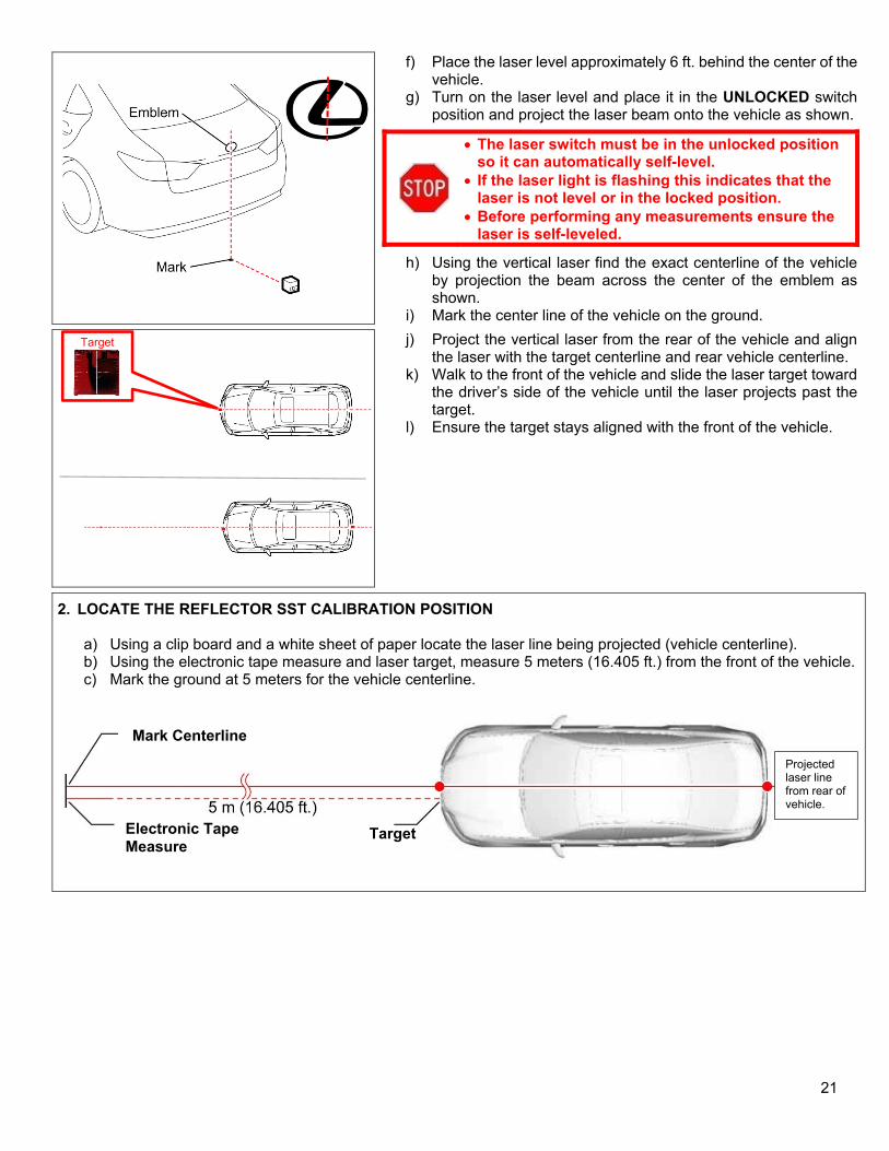
c) Using the vertical laser find the exact centerline of the vehicle by projecting the beam across the center of the emblem as shown.
d) Mark the center line of the vehicle on the ground even with the front of the vehicle.
e) Place the laser target on the front vehicle centerline mark facing the rear of the vehicle.
21
f) Place the laser level approximately 6 ft. behind the center of the vehicle.
g) Turn on the laser level and place it in the UNLOCKED switch position and project the laser beam onto the vehicle as shown.
The laser switch must be in the unlocked position so it can automatically self-level.
If the laser light is flashing this indicates that the laser is not level or in the locked position.
Before performing any measurements ensure the laser is self-leveled.
h) Using the vertical laser find the exact centerline of the vehicle by projection the beam across the center of the emblem as shown.
i) Mark the center line of the vehicle on the ground.
j) Project the vertical laser from the rear of the vehicle and align the laser with the target centerline and rear vehicle centerline.
k) Walk to the front of the vehicle and slide the laser target toward the driver’s side of the vehicle until the laser projects past the target.
l) Ensure the target stays aligned with the front of the vehicle.
2. LOCATE THE REFLECTOR SST CALIBRATION POSITION a) Using a clip board and a white sheet of paper locate the laser line being projected (vehicle centerline). b) Using the electronic tape measure and laser target, measure 5 meters (16.405 ft.) from the front of the vehicle. c) Mark the ground at 5 meters for the vehicle centerline.
Target
Mark Centerline
Electronic Tape Measure
Target
Projected laser line from rear of vehicle.

22
d) Measure 11mm from the centerline of the vehicle toward the driver’s side as shown. e) Mark the ground the ground to identify the reflector placement position. f) Measure 0.5 meters to the left and right of the calibration location and mark them on the ground. g) Place the reflector SST in this location and align the center mark on the SST with the reflector placement mark.
SST: 09870-60000 (Stick and Base) 09870-60040-02 (Reflector C)
Note: The 3 measured marks will be used during the calibration procedure using Techstream, it is crucial that you measure these locations.
3. SET REFLECTOR C HEIGHTS
REFLECTOR HEIGHT ADJUSTMENT PROCEDURE VIDEO
a) Place the tripod and laser level in front of the vehicle. b) Level the tripod base and head using the built in bubble levels. c) Turn on the laser level to the UNLOCKED position with both the
vertical and horizontal laser lines being projected. d) Adjust the heights of the tripod head and laser until the laser line
crosses over the center the Toyota emblem as shown.
The laser switch must be in the unlocked position so it can automatically self-level.
If the laser light is flashing this indicates that the laser is not level or in the locked position.
e) Turn the self-leveling laser 180 degrees and align it with the calibration reflector and SST.
Do not change the heights of the laser level when performing this step.
f) Adjust the height of Reflector C until it aligns with the laser lines as shown.
Do not change the heights of the laser level when performing this step.
Centerline Mark
Reflector Calibration Mark 11 mm (0.433 in.) toward Driver’s Side
0.5 Meter Mark
0.5 Meter Mark

23
g) Adjust the height of Reflector C in accordance with the slope calculation sheet value at the bottom of the page.
You must adjust the reflector C height to ensure it is at the correct heights for calibration.
The adjustment heights value can vary based on floor slope.
Example of Upward Slope
D. CALIBRATE THE HORIZONTAL ANGLE OF THE MILLIMETER WAVE RADAR SENSOR.
HORIZONTAL ANGLE CALIBRATION VIDEO
During the horizontal calibration procedure the utility will not prompt all the steps that are
required. Ensure to follow all steps outlined in this TI and video to ensure the calibration is
performed properly.
1. ADJUST RADAR SENSOR HORIZONTAL ANGLE a) Connect Techstream b) Turn the ignition switch to IG on (Engine Off/Ready Off) c) Turn the cruise control switch on and confirm the light
illuminates on the instrument cluster. d) Turn the PCS cancel switch on. e) Confirm reflector is located and adjusted to the correct heights. f) Select the Radar Cruise ECU in the Techstream g) Select Utility h) Select Beam Axis Adjustment and Click Next
Note: After clicking “Next” the brake buzzer will sound for approximately 1 second when the screen changes to the system adjustment screen.
i) When the adjusting screen appears move the reflector away from the reflector placement point and outside of the calibration area. Correct Distance Value: 0.0 m
If the screen displays a value other than 0.0m it is
detecting other metallic object in the calibration
area, remove these objects out of the area. If the
objects cannot be removed you must calibrate the
system in a different area.

24
j) Return Reflector C to the calibration placement point. k) Check the value of the distance measurement:
Correct Distance Value: 4.5 to 5.5 m (14.8 to 18.0 ft.) Correct Left/Right Side Value: 3.0 degrees or less
l) Validate the radar sensor is correctly recognizing the reflector C.
m) Move the reflector 0.5 meters to each side of the calibration placement point.
n) Confirm that the values change in correspondence to the reflector location.
o) Return the reflector to the calibration placement position.
p) Click “Next” to adjust the horizontal angle of the sensor.
Note: After clicking “Next” the brake buzzer will sound
for approximately 1 second. The radar sensor will automatically adjust the
horizontal angle.
q) When the “Beam Axis adjustment is complete message appears turn off the ignition.
r) Turn IG on again and confirm that no related DTC set for Beam Axis Adjustment.
IX. RESTORE VEHICLE
A. CONFIRM VEHICLE CONDITION 1. CHECK AND CLEAR DTCS 2. RESTORE SYSTEM SETTINGS AND DATA 3. INITIALIZE PARKING ASSIST MONITOR SYSTEM
a) When “System initializing” is displayed on the multi-display, correct the steering angle neutral point by turning the steering wheel full right and then full left on level ground.
Note: The engine must be running with the car in park and parking brake applied.
4. PERFORM TEST DRIVE
B. REASSEMBLE VEHICLE
1. REINSTALL COOL AIR INTAKE DUCT SEAL
b) Install the Cool Air Intake Duct Seal and 9 clips.

25
X. APPLY CORRECTION STICKER TO OWNER’S MANUAL
1. CHECK OWNER’S MANUAL PUBLICATION NUMBER
a) Locate the owner’s manual. b) Inspect the publication number and the table below to determine
which 2 pages require the updates:
Publication # Page Page OM33A01U 258 310 OM33A60U 262 314 OM33B36U
268 325 OM33B99U
2. INSTALL CORRECTION LABELS a) Locate the FCC ID # on the applicable pages and install the label
as shown. Note: Location of the FCC number will vary by publication number and page, ensure you find the correct location. b) Confirm the label has been attached to both applicable pages.
◄ VERIFY REPAIR QUALITY ► − Confirm the correct Driver Support ECU is installed − Confirm the floor slope was correctly calculated and the vertical angle was properly set for the millimeter
wave radar sensor − Confirm the vehicle centerline was correctly identified and the horizontal calibration procedure was
performed properly
If you have any questions regarding this update, please contact your area representative.