Embed Size (px)
Citation preview

Technical Information
Split Air-Air Cool OnlyAVO-74 to 174FG/BLI-74 to 154, BCI-74 to 174,BVI-74 and 154
Ref: N-27513 0606
E U R O V E N TCERTIFIED PERFORMANCE
CGM-97/013AC
CO
RD
ING
TO
ISO
140
01 S
TAN
DA
RD
S
ER-0028/1991AC
CO
RD
ING
TO
ISO
900
1 S
TAN
DA
RD
S
Clima Roca York S.L. is participating in the EUROVENT Certification Program.Products are as listed in the EUROVENT Directory of Certified Products,in the program AC1, AC2, AC3, LCP and FC.


3
- General dimensions 30- General characteristics 31- Dimensions with packing, and weights 31- Installation 31- Wiring diagrams 32 - 33
Internal electric heaters for BCI-74 to 174 34
- Technical spcifications 34- Assembly and general dimensions 34- General characteristics 35- Dimensions with packing and weights 35- Installation 35- Wiring diagrams 36 - 37
Internal electric heaters for BVI-74 to 154 38
- Technical specifications 38- Assembly and general dimensions 38- General characteristics 39- Dimensions with packing, and weights 39- Installation 39- Wiring diagrams 40 - 41
Octopus plenum 42
Low ambient kit 44
- Technical specifications 44- Installation 44- Operation 45- Cables 45- Wiring diagram 46
Index
General Information 5
- General description 5- Nomenclature 5
Technical Specifications 5
- Mechanical specifications 5- Ambient thermostat DPC-1 6- Physical data 6- Limits of use 7- General dimensions 8 - 12- Indoor unit diagrams 12- Variant chart 13- Nominal capacities 14- Test conditions 14- Correcting factors 14 - 15- Nominal flows 15- Sensible cooling capacities 16 -19- Fan services 20 - 22- Electrical characteristics 23
Control Board 24
- Wiring diagrams 25 - 27- Configuration of switches 28
Accessories 29
- Standard accessories 29
Duct electric heaters for BLI-74 to 154 30
- Technical specifications 30
Page Page


5
General InformationGeneral descriptionThe AVO series units are the outdoor units of a cool only splittype air conditioner equipped with an horizontal dischargeaxial fan and ready for direct installation outdoors or in a well-ventilated indoor area. Of low noise level, they can be in-stalled on terraces, balconies, etc. without any difficulty.The AVO-74 to 174 FG units are compatible with the BLI andBCI indoor units. Their design and limited dimensions allowinstalling them horizontally in corridors ceilings, attics, etc.Maintenance of the BLI and BCI units can be carried out to-tally from the bottom, which increases installation possibili-ties. The indoor units can be equipped with an electric heater,as an optional accessory, to provide backup heat if needed.The AVO-74, 104 and 154 FG units are compatible with theBVI-74, 104 and 154 indoor units.
Nomenclature
Technical SpecificationsMechanical specificationsCompressorVertical hermetic Scroll type, mounted on antivibratory sup-ports and equipped with internal protection of the motor. In-cludes an electric heater for heating oil in the sump, whichmakes start-ups easier and avoids oil being removing fromthe compressor.
CoilsOf a large surface, made of grooved copper tubing andnotched aluminium fins.
Fans (outdoor units)Axial with free air discharge, no ducts. Silent operation with atwo-speed motor.
Fans (indoor units)Centrifugal, with double helix and three-speed direct drivemotor, and mounted on antivibratory supports.
Casing (outdoor units)Made of galvanised steel sheeting and finished with ovenpolymerised powdered paint for outdoor installation. The com-pressor chamber is insulated internally so as to avoid con-densation and reduce noise level.
Casing (indoor units)Made of galvanised steel sheeting. Insulated internally so asto avoid condensation and reduce noise level. Includes agalvanised sheeting tray with its corresponding drain for col-lecting condensed water from the coil.
Cooling circuitMade of welded copper tubing. The units are supplied withtheir corresponding optimised refrigerant charge, dehydratedand having passed the maximum pressure and airtightnesstests. Refrigerant expansion is carried out by means of cali-brated holes and distributors located in the indoor units. Theoutdoor units include high pressure switches, suction anddischarge pressure intakes and valves for the cooling inter-connection at the job site.
RefrigerantThese units are manufactured with R-407C refrigerant.
Control PanelAccessible directly from outside. Includes connecting strip,electronic board and probes, power supply contactor, oper-ating relay and transformer. Complies with the Europeanstandards in force.
ThermostatThe AVO-FG units include, as standard equipment, the elec-tronic DPC-1 thermostat.
AVO = Vertical outdoor unit withaxial fan.
BCI = Horizontal indoor unit.BLI = Low level horizontal indoor
unit.BVI = Vertical indoor unit.
R-407C
F = Cool only
Cooling 74FG = 7 100 W 94FG = 8 400 W104FG = 9 800 W124FG = 11 900 W154FG = 14 000 W174FG = 16 300 W
Power supply:21 = 230.1.5022 = 230.3.5038 = 400.3.50
Edition
AVO 104 F G 38 E1

6
Ambient thermostat DPC-1Programmable digital thermostat with communicationThis thermostat was designed to give close control of theambient temperature and graphic information regarding themode it is currently operating in. This control unit, in accord-ance with the differential between the programmed tempera-ture and the ambient temperature, responds varying the on/off cycles.The liquid crystal display (LCD) normally indicates the ambi-ent temperature, operating mode and whether the system isin heat or cool.It allows selecting different set point temperatures for cool andheat, besides choosing between ºC and ºF on the display.Fan operation can be in continuous or automatic mode, off orin operation along with the compressor. Three speeds canbe selected.The controls are beneath a cover.
Physical DataOutdoor units
230.1.50230/400.3.50
Model AVO-74FG AVO-94FG AVO-104FG AVO-124FG AVO-154FG AVO-174FG
Amount 1
Type Scroll
kW 2.55 3.22 3.63 4.10 4.32 5.43
Power supply V.ph.Hz 230.1.50 230.1.50 230/400.3.50 230/400.3.50 230/400.3.50
Amount 1
Front area m2 0.57 0.72 0.72 0.96 0.96 0.96
Tubing diameter 3/8"
Tubing depth x height 2 x 28 2 x 36 2 x 36 2 x 48 2 x 48 2 x 48
Amount 1 1 1 2 2 2
Nominal power kW 0.13 0.13 0.13 2 x 0.13 2 x 0.13 2 x 0.13
Motor nominal r.p.m. 910
Power supply V.ph.Hz 230.1.50
Cooling connections 3/8" x 5/8" 3/8" x 3/4 3/8" x 3/4" 3/8" x 7/8" 3/8" x 7/8" 3/8" x 7/8"
Dimensions with packing mm 1040x470/824 1040x470/1027 1040x470/1027 1040x470/1332 1040x470/1332 1040x470/1332
Nett kg 89 102 111 122 133 136
Gross kg 95 108 118 129 140 143
Nominal power
AUTOAUTO
4 ��
0h 2 4 6 8 10 12 14 16 18 20 22 24
�������
PROG
Compressor
Coil
Fanmotor
Approx.weight

7
Air intake temperatureto indoor coil (WB)
Nominal 400 VNominal 230 V
Minimum
198 342254
Maximum
436
Maximum °CMinimum °C
Minimum19 46 15 23
Maximum
Maximum °CMinimum °C
Voltage limits Air intake temperatureto outdoor coil (DB)
Nominal power W 250 250 505 700 260 475 475 665 1 000 475 505 700
Power supply V.ph.Hz 230.1.50
Motor nominal r.p.m. 1 340 1 370 1 420 1 350 950 950 950 870 1 100 950 950 950
Number of turbines 2 2 2 2 2 2 2 2 2 1 1 2
Turbine Ø mm 146 160 185 190 190 190 190 240 240 240 240 240
Turbine width mm 220 240 240 200 190 190 190 240 240 240 240 240
Amount 1
Front area m2 0.26 0.29 0.304 0.352 0.228 0.279 0.279 0.463 0.463 0.377 0.377 0.617
Tubing diameter 3/8"
Tubing, depth x height 3 x 10 4 x 11 4 x 12 4 x 14 3 x 12 4 x 15 4 x 15 3 x 20 3 x 20 2 x 27 3 x 27 3 x 27
kg 42 47 52 60 50 65 65 88 89 74 77 113
Height mm 268 299 285 335 350 350 350 430 430 1 595 1 595 1 595
Width mm 1 144 1 144 1 100 1 100 860 860 860 1 100 1 100 820 820 1 155
Depth mm 502 542 710 750 715 935 935 1 139 1 139 490 490 490
Approximate weight
Dimensions
Fan
Model BLI-74 BLI-104 BLI-124 BLI-154 BCI-74 BCI-104 BCI-124 BCI-154 BCI-174 BVI-74 BVI-104 BVI-154
Indoor units
Limits of use
Coil
Notes: WB = Wet bulb. DB = Dry bulb.

8
General dimensions mm
AVO-74FG
AVO-94 and 104FG
762
32
905
405
10
323
152
430440
10
460
Ø 11,5
MINIMUMCLEARANCE 150
MINIMUMCLEARANCE 300
MINIMUMCLEARANCE 1500
MINIMUMCLEARANCE 600
LIQUID CONNECTION3/8" SAE
GAS CONNECTION5/8" SAE
32
905405
323
152
430
440
10
46010
Ø 11,5
933
965
MINIMUMCLEARANCE 150
MINIMUMCLEARANCE 300
MINIMUMCLEARANCE 1500
MINIMUMCLEARANCE 600
GASCONNECTION 3/4" SAE
LIQUIDCONNECTION3/8" SAE

9
Model A B C D E F G H I J K L M N O P
268 465 21 78 229 19 55 17 24 75 75 1 144 147 147 169
299 505 26 104 260 19 55 17 24 75 75 1 144 147 147 169
285 710 26 90 255 15 15 15 15 72 34 1 100 164 86 169
335 750 23 75 300 15 15 15 15 72 34 1 100 125 125 235
BLI-74
BLI-104
BLI-124
5/8"SAE
3/4"SAE
7/8"Weld
BLI-1547/8"Weld
General dimensions mm
BLI-74 to 154
AVO-124, 154 and 174FG
1270
3212
38405
905
323
152
430
440
10
460
10
Ø 11,5
MINIMUMCLEARANCE 150
MINIMUMCLEARANCE 300
MINIMUMCLEARANCE 1500
MINIMUMCLEARANCE 600
LIQUID CONNECTION
( 3/8" SAE)
GAS CONNECTION
(WELD 7/8")
L
1070
H
G
I
15
E
N
O
850
C
D
35
M
A20
2319
Ø 19297
994B
MINIMUMCLEARANCE 300
MINIMUMCLEARANCE 300
GASCONNECTION (F)
LIQUIDCONNECTION3/8" SAE
9 x 22 CLIP
J
K
P

10
Model A B
3/8" SAE 3/4" SAEBCI-104
BCI-124 3/8"SAE
7/8"WELD
General dimensions mm
BCI-74
BCI-104 and 124
6067
33100
100
660
20
2516
016
5
640
55
860
350
40
40
40
40
783
700
83015
15
3128
237
5533
22
MINIMUMCLEARANCE 300
MINIMUMCLEARANCE 300
GAS CONNECTION5/8" SAE
ELECTRICALCONNECTIONS Ø23
DRAIN PIPE EXT.Ø 16
LIQUIDCONNECTION 3/8" SAE
3535
35
6576
57
39
100
100
660
20
2516
016
5
860
55
860
350
68 404340
40
40
40
40
783
920
83015
15
3128
237
55
33
22MINIMUMCLEARANCE 300
MINIMUMCLEARANCE 300
LIQUIDCONNECTION( A ) ELECTRICAL
CONNECTIONS Ø23DRAIN PIPE EXT.Ø 16
GASCONNECTION ( B )

11
General dimensions mm
BCI-154 and 174
BVI-74 and 104
Model A B
3/8" SAE 5/8" SAEBVI-74
BVI-104 3/8" SAE 3/4" SAE
664
420
1400
138
25265430
303198,5
700198,5
ELECTRICALCONNECTIONS
LIQUIDCONNECTION (A)
GASCONNECTION (B)
DRAINCONNECTION(3/4" G.)
MINIMUMCLEARANCE 300 40
40
40
40
1023
1124
1078
11
11
5333
938
33
22
55
DRAIN PIPE EXT.Ø 16
7657
47
124
124
852
20
2521
219
3
1064
55
1100
430
176 404340
LIQUIDCONNECTION(3/8" SAE)
GAS CONNECTION(WELD 7/8")
MINIMUMCLEARANCE 300
ELECTRICALCONNECTIONS Ø23

12
BCI
BLI
BVI
General dimensions mm
BVI-154
Indoor unit diagrams
SUPPORT
AIROUTLET
ACCESSPANEL
TO CONTROLPANEL
ELECTRICALAND COOLINGCONNECTIONS
TO CONTROLPANEL
COILSUPPORT
OPTIONALELECTRICHEATER
CONDENSEDWATER DRAINCONNECTION
FILTER
AIRINTAKE
SUPPORT
COOLINGCONNECTIONS
COILSUPPORT
CONDENSEDWATER DRAINCONNECTION
FILTER OPTIONALELECTRICHEATER
AIRINTAKE
ACCESSPANEL
AIROUTLET
ELECTRICALCONNECTIONS
ACCESS PANELTO ELECTRICCONTROL BOX
AIRINTAKE
ELECTRICHEATER
(ACCESSORY)
ACCESSPANELTO UNIT
DRAINCONNECTION
COOLINGCONNECTIONS
ELECTRICALCONNECTIONS
AIR OUTLET
ACCESSPANELTO UNIT
664
420
1400
138
25
265430
105,5301
237301
105,51050
ELECTRICALCONNECTIONS
GAS CONNECTION7/8" WELD
LIQUID CONNECTION3/8" SAE
DRAINCONNECTION(3/4" G.)

13
Variant chart AVO-FG-BLI, BCI, BVI
BVI-154, 230.1.50
BVI-104, 230.1.50
BVI-74, 230.1.50
BCI-124, 230.1.50
BCI-154, 230.1.50
AVO-94FG, 230.1.50
230.1.50AVO-104FG, 230.3.50
400.3.50
AVO-124/FG, 230.3.50 400.3.50
AVO-154FG, 230.3.50 400.3.50
AVO-174FG, 230.3.50 400.3.50
BCI-174, 230.1.50
AVO-74FG, 230.1.50
BCI-124, 230.1.50
BCI-74, 230.1.50 BLI-74, 230.1.50
BLI-104, 230.1.50BCI-104, 230.1.50
BLI-124, 230.1.50
BLI-154, 230.1.50

14
Flow % 70 80 90 100 110 120 130
5 3 1.5 0 -1 -2 -2.5Correction in °C on real temperature ofair going to the outdoor coil
BLI-74 7 100 2 890
BCI-74
BVI-74
BLI-104 8 400 3 350
BCI-104
BLI-104 9 800 3 970
BCI-104
BVI-104
BLI-124 11 900 5 380
BCI-124
BLI-154
BCI-124
BCI-154 14 000 5 620
BVI-154
BCI-174 16 300 6 400
AVO-124FG
AVO-154FG
Outdoor unit Indoor unit Cooling capacity W Consumption W
AVO-74FG
AVO-94FG
AVO-104FG
AVO-174FG
Nominal capacities
Test conditions
Correcting factorsCorrecting factors for cooling capacitiesFor flows that differ from the nominal flows of the indoor coil.
Correction of the real temperature of air intake to the outdoorcoil for flows that differ from the nominal values.
VoltageLength
interconnectingtubing
Summer
Outdoor temp. °C Indoor temp. °C
DB WB DB WB
230 or 400 7.5 meters 35 24 27 19
Flow % 80 90 100 110 120 130
Total capacity 0.960 0.980 1 1.016 1.032 1.046
Sensible capacity 0.945 0.973 1 1.038 1.075 1.118
Comp. absorbed power 0.980 0.990 1 1.009 1.017 1.025

15
Nominal flowModel
Available pressureindoor fan
Pam3/h m3/s
AVO-74FG 3 100 0.86
AVO-94FG 3 100 0.86
AVO-104FG 3 100 0.86
AVO-124FG 6 200 1.72
AVO-154FG 6 200 1.72
AVO-174FG 6 200 1.72
ModelFlow
Nominal V. m3/h Nominal V. m3/s
Nominal flowsIndoor unitsThe cooling capacities of the corresponding tables are validfor the following nominal flows.
For other flows, apply the correcting factors of the correspond-ing table.
(1) Fan connected in 2nd speed. (2) Fan connected in 1st speed.
Outdoor units
BCI-74 1 670 0.46 25
BLI-74 1 315 0.36 25
BVI-74 1 975 0.55 25
BCI-104 2 300 0.64 37
BLI-104 2 060 0.57 37
BVI-104 2 430 0.68 50
BLI-124 2 140 0.59 50
BLI-154 2 700 0.75 50
BVI-154 2 910 0.81 80
BCI-124 2 300 0.64 50
BCI-154/174 (1)2 910/4 200(2) (1)0.80/1.16(2) 50

16
Sensible cooling capacities
22 8 520 2 655 3 483 4 724 5 554 2.20
19 7 668 3 943 4 771 6 013 6 842 2.29
17 7 100 4 785 5 613 6 856 7 100 2.40
22 7 882 2 429 3 257 4 499 5 327 2.48
19 7 100 3 719 4 547 5 790 6 618 2.61
17 6 532 4 303 5 131 6 374 6 532 2.75
22 7 100 2 178 3 006 4 248 5 076 2.88
19 6 390 3 467 4 294 5 536 6 364 3.01
17 5 822 4 253 5 081 5 822 5 822 3.14
22 7 942 2 422 3 325 4 681 5 586 2.05
19 7 148 3 827 4 730 6 086 6 991 2.14
17 6 618 4 750 5 653 6 618 6 618 2.24
22 7 347 2 218 3 122 4 478 5 381 2.31
19 6 618 3 626 4 530 5 885 6 618 2.44
17 6 089 4 106 5 009 6 089 6 089 2.56
22 6 618 1 993 2 896 4 252 5 155 2.68
19 5 956 3 396 4 300 5 656 5 956 2.80
17 5 427 4 268 5 172 5 427 5 427 2.93
22 7 374 2 298 3 014 4 089 4 807 1.90
19 6 637 3 413 4 129 5 204 5 922 1.99
17 6 145 4 141 4 858 5 933 6 145 2.08
22 6 822 2 102 2 819 3 894 4 610 2.15
19.5 6 145 3 219 3 936 5 011 5 728 2.26
17 5 654 3 725 4 441 5 517 5 654 2.38
22 6 145 1 885 2 602 3 677 4 393 2.49
19 5 531 3 000 3 717 4 792 5 508 2.60
17 5 039 3 681 4 398 5 039 5 039 2.72
22 10 080 3 113 4 156 5 721 6 766 2.75
19.5 9 072 4 406 5 450 7 015 8 060 2.88
17 8 400 5 800 6 843 8 400 8 400 3.02
22 9 325 2 849 3 893 5 458 6 501 3.11
19.5 8 400 4 152 5 195 6 760 7 804 3.28
17 7 728 5 294 6 337 7 728 7 728 3.44
22 8 400 2 557 3 600 5 166 6 209 3.61
19.5 7 560 3 861 4 904 6 470 7 513 3.77
17 6 888 5 178 6 221 6 888 6 888 3.94
Sensible capacity (W)
Compressorabsorbed
power
Totalcapacity
Dry outdoorair temperature
°C (DB)
Humid intakeair temperature
°C (WB)
45
35
ModelDry intake air temperature to coil °C (DBS)
25
AVO-74FGBVI-74
25
35
45
25
35
45
AVO-94FGBLI-104
AVO-74FGBCI-74
kWWWWWW
292422 27
45
35
25
AVO-74FGBLI-74

17
Sensible cooling capacities
22 10 434 3 108 4 554 6 722 8 169 2.86
19.5 9 391 4 922 6 368 8 536 9 391 3.00
17 8 695 6 833 8 279 8 695 8 695 3.13
22 9 652 2 851 4 297 6 465 7 910 3.24
19.5 8 695 4 671 6 117 8 286 8 695 3.41
17 7 999 6 218 7 663 7 999 7 999 3.58
22 8 695 2 565 4 010 6 178 7 624 3.75
19.5 7 930 4 385 5 831 7 826 7 826 3.92
17 7 130 6 219 7 130 7 130 7 130 4.09
22 10 964 3 428 4 469 6 031 7 075 2.66
19.5 9 868 4 712 5 753 7 316 8 359 2.78
17 9 137 6 106 7 147 8 709 9 137 2.91
22 10 142 3 136 4 177 5 739 6 780 3.00
19.5 9 800 4 430 5 471 7 032 8 075 3.16
17 8 406 5 549 6 591 8 153 8 406 3.32
22 9 137 2 811 3 853 5 415 6 456 3.48
19.5 8 223 4 109 5 150 6 712 7 753 3.63
17 7 492 5 419 6 460 7 492 7 492 3.80
22 11 362 3 466 4 754 6 687 7 977 2.80
19.5 10 225 5 071 6 359 8 293 9 583 2.94
17 9 468 6 785 8 075 9 468 9 468 3.07
22 10 509 3 175 4 464 6 396 7 685 3.17
19.5 9 468 4 789 6 077 8 011 9 299 3.34
17 8 711 6 106 7 394 8 711 8 711 3.51
22 9 468 2 852 4 140 6 073 7 361 3.68
19.5 8 521 4 468 5 756 7 689 8 521 3.84
17 7 764 6 096 7 384 7 764 7 764 4.01
22 11 661 3 527 4 943 7 069 8 488 3.29
19.5 10 495 5 297 6 714 8 839 10 258 3.34
17 9 718 7 179 8 596 9 718 9 718 3.39
22 10 787 3 233 4 650 6 774 8 191 3.53
19.5 9 718 5 011 6 428 8 554 9 718 3.78
17 8 940 6 294 7 710 8 940 8 940 4.18
22 9 718 2 905 4 322 6 447 7 864 4.63
19.5 8 746 4 685 6 101 8 227 8 746 4.73
17 7 968 6 478 7 895 7 968 7 968 4.83
45
35
25
AVO-104FGBCI-104
25
35
45
25
35
45
AVO-104FGBVI-104
AVO-104FGBLI-104
kWWWWWW
292422 27
45
35
25
AVO-94FGBCI-104
Sensible capacity (W)
Compressorabsorbed
power
Totalcapacity
Dry outdoorair temperature
°C (DB)
Humid intakeair temperature
°C (WB)Model
Dry intake air temperature to coil °C (DBS)

18
Sensible cooling capacities
22 14 280 4 492 5 794 7 750 9 052 3.81
19.5 12 851 6 091 7 394 9 349 10 656 3.99
17 11 900 7 837 9 144 11 100 11 900 4.18
22 13 207 4 106 5 409 7 364 8 667 4.31
19.5 11 900 5 721 7 023 8 979 10 281 4.54
17 10 944 7 018 8 322 10 276 10 949 4.76
22 11 900 3 677 4 984 6 935 8 242 4.99
19.5 10 710 5 301 5 628 8 559 9 861 5.22
17 9 754 6 935 8 242 9 759 9 759 5.45
22 15 072 4 738 6 119 8 189 9 572 3.33
19.5 13 565 6 436 7 816 9 887 11 269 3.48
17 12 560 8 286 9 666 11 737 12 560 3.65
22 13 942 4 332 5 713 7 783 9 164 3.77
19.5 12 560 6 044 7 425 9 495 10 875 3.96
17 11 555 7 506 8 886 10 956 11 555 4.16
22 12 560 3 883 5 264 7 334 8 714 4.36
19.5 11 304 5 599 6 979 9 050 10 431 4.56
17 10 299 7 334 8 715 10 299 10 299 4.76
22 16 800 5 170 6 953 9 630 11 416 4.32
19.5 15 400 7 385 9 168 11 845 13 632 4.53
17 14 000 9 764 11 547 14 000 14 000 4.73
22 15 540 4 733 6 518 9 193 10 977 4.90
19.5 14 000 6 963 8 746 11 422 13 206 5.16
17 12 880 8 931 10 716 12 880 12 880 5.41
22 14 000 4 249 6 032 8 708 10 493 5.67
19.5 12 600 6 480 8 265 10 941 12 600 5.93
17 11 480 8 733 10 517 11 480 11 480 6.19
22 15 516 4 760 6 447 8 976 10 665 3.31
19.5 13 964 6 857 8 543 11 074 12 763 3.46
17 12 930 9 105 10 791 12 930 12 930 3.62
22 14 352 4 358 6 046 8 575 10 262 3.74
19.5 12 930 6 468 8 155 10 685 12 371 3.94
17 11 896 7 885 9 590 11 896 11 896 4.13
22 12 930 3 913 5 600 8 130 9 817 4.33
19.5 11 637 6 025 7 721 10 242 11 637 4.52
17 10 603 8 156 9 843 10 603 10 603 4.73
45
35
25
AVO-154FGBLI-154
25
35
45
25
35
45
AVO-154FGBCI-124
AVO-124FGBCI-124
kWWWWWW
292422 27
45
35
25
AVO-124FGBLI-124
Sensible capacity (W)
Compressorabsorbed
power
Totalcapacity
Dry outdoorair temperature
°C (DB)
Humid intakeair temperature
°C (WB)Model
Dry intake air temperature to coil °C (DBS)

19
Sensible cooling capacities
22 16 800 5 319 6 790 8 996 10 469 3.67
19.5 15 120 7 120 8 591 10 798 12 272 3.84
17 14 000 9 095 10 566 12 772 14 000 4.02
22 15 540 4 861 6 332 8 538 8 980 4.15
19.5 14 000 6 680 8 150 10 357 11 827 4.37
17 12 880 8 219 9 690 11 896 12 880 4.58
22 14 000 4 354 5 825 8 031 9 503 4.81
19.5 12 600 6 179 7 650 9 856 11 327 5.02
17 11 480 8 024 9 494 11 480 11 480 5.24
22 15 736 4 827 6 538 9 103 10 816 4.11
19.5 14 162 6 954 8 664 11 230 12 943 4.40
17 13 113 9 233 10 944 13 113 13 113 4.60
22 14 555 4 420 6 131 8 697 10 407 4.79
19.5 13 113 6 559 8 271 10 836 12 546 4.97
17 12 064 7 997 9 726 12 064 12 064 5.58
22 13 113 3 969 5 679 8 245 9 956 6.16
19.5 11 802 6 111 7 830 10 387 11 802 6.26
17 10 753 8 271 9 982 10 753 10 753 6.46
22 19 560 5 909 8 309 11 908 14 311 4.73
19.5 17 604 8 909 11 308 14 907 17 312 4.96
17 16 300 12 094 14 493 16 300 16 300 5.18
22 18 093 5 417 7 816 11 415 13 815 5.35
19.5 16 300 8 430 10 829 14 429 16 300 5.63
17 14 996 10 344 12 745 14 996 14 996 5.91
22 16 300 4 868 7 267 10 867 13 266 6.19
19.5 14 670 7 883 10282 13 883 14 670 6.48
17 13 366 10 921 13 320 13 366 13 366 6.76
45
35
25
AVO-174FGBCI-174
25
35
45
AVO-154FGBVI-154
kWWWWWW
292422 27
45
35
25
AVO-154FGBCI-154
Sensible capacity (W)
Compressorabsorbed
power
Totalcapacity
Dry outdoorair temperature
°C (DB)
Humid intakeair temperature
°C (WB)Model
Dry intake air temperature to coil °C (DBS)

20
Fan services, BLI indoor units
0 1 660 0.46 226
20 1 350 0.37 211
40 1 220 0.34 197
60 990 0.27 181
0 1 285 0.35 191
20 1 170 0.32 177
40 1 045 0.29 164
60 885 0.24 152
0 922 0.25 144
20 849 0.23 135
40 723 0.20 126
60 652 0.18 120
0 2 230 0.62 386
20 2 155 0.60 374
40 2 000 0.55 360
60 1 880 0.52 344
0 1 730 0.48 315
20 1 680 0.46 304
40 1 600 0.44 288
60 1 520 0.42 278
0 1 415 0.39 275
20 1 375 0.38 267
40 1 340 0.37 254
0 2 420 0.67 555
50 2 140 0.59 505
80 1 940 0.54 475
100 1 760 0.49 455
0 2 190 0.60 465
50 2 010 0.56 405
80 1 840 0.51 375
100 1 640 0.45 350
0 2 160 0.60 460
50 1 900 0.53 380
80 1 730 0.48 350
100 1 550 0.43 325
0 2 880 0.80 700
50 2 720 0.75 650
80 2 550 0.71 620
100 2 400 0.66 595
0 2 450 0.68 565
50 2 340 0.65 525
80 2 230 0.62 495
100 2 100 0.58 465
0 2 190 0.61 510
50 2 100 0.58 485
80 2 020 0.56 455
100 1 920 0.53 425
FanspeedModel
Static pressureavailable (1)
Pa
Air flow Absorbedpower
W
High
Medium
Low
High
Medium
Low
BLI-74
BLI-124
High
Medium
Low
BLI-104
m3/h m3/s
High
Medium
Low
BLI-154
(1) Calculated with wet coil.
21
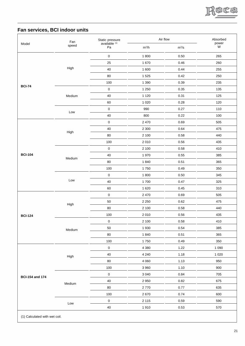
Fan services, BCI indoor units
0 1 800 0.50 265
25 1 670 0.46 260
40 1 600 0.44 255
80 1 525 0.42 250
100 1 390 0.39 235
0 1 250 0.35 135
40 1 120 0.31 125
60 1 020 0.28 120
0 990 0.27 110
40 800 0.22 100
0 2 470 0.69 505
40 2 300 0.64 475
80 2 100 0.58 440
100 2 010 0.56 435
0 2 100 0.58 410
40 1 970 0.55 385
80 1 840 0.51 365
100 1 750 0.49 350
0 1 800 0.50 345
40 1 700 0.47 325
60 1 620 0.45 310
0 2 470 0.69 505
50 2 250 0.62 475
80 2 100 0.58 440
100 2 010 0.56 435
0 2 100 0.58 410
50 1 930 0.54 385
80 1 840 0.51 365
100 1 750 0.49 350
0 4 380 1.22 1 090
40 4 240 1.18 1 020
80 4 060 1.13 950
100 3 960 1.10 900
0 3 040 0.84 705
40 2 950 0.82 675
80 2 770 0.77 635
100 2 670 0.74 600
0 2 115 0.59 590
40 1 910 0.53 570
m3/h
BCI-74
BCI-104
BCI-124
High
Medium
High
Medium
High
Low
High
BCI-154 and 174
Medium
Low
Medium
m3/s
Low
FanspeedModel
Static pressureavailable (1)
Pa
Air flow Absorbedpower
W
(1) Calculated with wet coil.

22
Fan services, BVI indoor units
0 2 010 0.56 440
20 1 990 0.55 425
40 1 975 0.55 415
60 1 960 0.54 400
80 1 940 0.54 395
100 1 925 0.53 385
120 1 905 0.53 375
0 1 465 0.41 340
20 1 395 0.39 337
40 1 380 0.38 332
60 1 370 0.38 325
80 1 350 0.38 320
100 1 320 0.37 310
120 1 300 0.36 300
0 2 510 0.7 490
20 2 475 0.69 475
40 2 430 0.68 455
60 2 385 0.66 445
80 2 365 0.66 435
100 2 320 0.64 425
120 2 275 0.63 415
140 2 215 0.62 402
0 1 990 0.55 425
20 1 975 0.55 415
40 1 960 0.54 400
60 1 940 0.54 395
80 1 925 0.53 385
100 1 905 0.53 375
120 1 835 0.51 362
140 1 780 0.49 360
0 3 315 0.92 690
20 3 310 0.92 670
40 3 255 0.90 650
60 3 190 0.89 630
80 2 910 0.86 610
100 2 750 0.81 580
0 2 255 0.63 580
20 2 150 0.56 570
40 2 080 0.55 555
m3/h
BVI-74
BVI-104
BVI-154
High(2nd)
Low(3rd)
High
High
Low
Low
m3/s
FanspeedModel
Static pressureavailable (1)
Pa
Air flow Absorbedpower
W
(1) Calculated with wet coil.

23
Electrical characteristicsOutdoor units
AVO-74FG 230.1.50 230.1.50 95 11.5 0.6 2.5 20
AVO-94FG 230.1.50 230.1.50 95 15.3 0.6 4 25
230.1.50 230.1.50 124 18 0.6 4 25
AVO-104FG 230.3.50 230.1.50 108 10.6 0.6 2.5 20
400.3.50 230.1.50 51 6.11 0.6 2.5 16
230.3.50 230.1.50 136 11.8 2 x 0.6 4 25
400.3.50 230.1.50 59.5 6.8 2 x 0.6 2.5 16
230.3.50 230.1.50 136 13.7 2 x 0.6 6 32
400.3.50 230.1.50 59.5 7.8 2 x 0.6 2.5 20
230.3.50 230.1.50 156 16 2 x 0.6 6 32
400.3.50 230.1.50 70.5 9.2 2 x 0.6 2.5 20
Nominal
FanCompressor
Power supply V.ph.Hz. Nominal consumption A
ModelFanCompressor
Start Nominal
Automaticswitch
(K curve) (1)
A
Powersupply cable
section(2)
mm2
AVO-124FG
AVO-154FG
AVO-174FG
Important: Automatic switch dimensioning and power supply and operating line sections are orientative and should be corrected in accordance withconditions at job site, length between units and legislation in force.Notes: 1.- K curve (DIN, VDE 0660-104). 2.- Based on copper conductors.
Indoor units
BLI-74 230.1.50 1.2 1.5
BLI-104 230.1.50 1.6 1.5
BCI-74 230.1.50 1.2 1.5
BCI-104 230.1.50 1.4 1.5
BLI-124 230.1.50 2.4 1.5
BCI-124 230.1.50 2.3 1.5
BCI-154 230.1.50 5.2 1.5
BLI-154 230.1.50 3.0 1.5
BCI-174 230.1.50 5.2 1.5
BVI-74 230.1.50 2.1 1.5
BVI-104 230.1.50 2.5 1.5
BVI-154 230.1.50 3 1.5
Power supplycable section
mm2
Fan
Power supply V.ph.Hz. Nominal consumption A
ModelFan
High speed

24
Control BoardThe control board of these units is common to both the coolonly as well as the heat pump units. By means of the resi-dent software in the board, this unit can control a compres-
sor, an electric heater (optional), the 3-speed indoor fan, the2-speed outdoor fan and the DPC-1 thermostat (for commu-nication).

25
Wiring Diagram, AVO-74, 94 and 104FG, 230.1.50
TH
E C
OM
PO
NE
NT
S I
NC
LUD
ED
IN
TH
ES
E B
OX
ES
AR
E N
OT
SU
PP
LIE
D B
Y T
HE
MA
NU
FAC
TU
RE
R
SH
IELD
ED
CA
BLE
10 x
0,2
2 m
m2
21 22
SU
MP
HE
ATE
R
230V
, 1
, 50H
z, N
,~
L1 L
1
Q1
6 4
X1.
..
Sec
tion
"B"
mm
Cu
2
5 3N
N
PE
INS
TALL
AT
JO
BS
ITE EO
(3)
KM
1
M1
M 1~
CO
MP
RE
SS
OR
L1
N
M3
OU
TD
OO
RFA
N
12
34
56
C3
4 Fµ
White
Yellow
Yellow/green
Brown
Black
1 2
32
(01)
(02)
13
24
51
32
45
B1
B2
B3
B4
J5J6
J7J8
GREEN
RED
BLACK
WHITE
J2S
ER
VIC
ET
ER
MIN
AL
SUCTION PROBE
LIQUID PROBE
DISCHARGE PROBE
OUTDOOR PROBE
T1
20 V
A
230V
24V
0V0V
P
1 2
KM
1
HP
1
J10
A1
ELE
CT
RO
NIC
BO
AR
D
I-23
63a
AV
O-7
4, 9
4 an
d 10
4FG
230
.1.5
0
HIGH PRESSURESWITCH 1(31 bar)
J4
14
5
46
(01)
C1
1 0
F2
4A
21
S3
P3
13
24
5
J9
6
Q2
H-
HIG
H S
PE
ED
M-
ME
DIU
M S
PE
ED
C-
CO
MM
ON
/NE
UT
RA
L
Blue
HM
6
Red
Blue
Black
White
8N
7
M2
IND
OO
RU
NITM 1
~
Yellow/green
C2
LM
HC
H-
HIG
H S
PE
ED
M-
ME
DIU
M S
PE
ED
L-
LOW
SP
EE
DC
- C
OM
MO
N/N
EU
TR
AL
3 Aux. heateroperation
F1
0,75
A
C
6
P
1 2
HP
2
HIGH PRESSURESWITCH 2(24 bar)
" S
1" C
ON
FIG
UR
ATIO
NO
F B
OA
RD
S1
MO
DE
L
AV
O-7
4F
AV
O-9
4F
AV
O-1
04F
Q (
A)
20 25 25
SE
CT
ION
"B"
mm
22,
5 4 4
230.
1.50
(03)
Sec
t. 6x
1,5
mm
Cu
2
J2
DP
C-1
TH
ER
MO
STA
T
GG
O/B
O/B
Y1
Y1
WW
M 1 ~
68
N7
3
RR
BB
X1
X1
12
34
56
78
ON
OF
F

26
Wiring Diagram, AVO-104FG, 400.3.50
RR
BB
X1
X1
SH
IELD
ED
CA
BLE
10 x
0,2
2 m
m2
TH
E C
OM
PO
NE
NT
S I
NC
LUD
ED
IN
TH
ES
E B
OX
ES
AR
E N
OT
SU
PP
LIE
D B
Y T
HE
MA
NU
FAC
TU
RE
R
M3
12
34
56
C3
4 Fµ
1 2
32
(01)
(02)
13
24
51
32
45
B1
B2
B3
B4
J5J6
J7J8
J2
T1
20 V
A
230V 0V
KM
1
J10
A1
I-23
64b
AV
O-1
04F
G 4
00.3
.50
J4
14
5
1 0
F2 4A
21
S3
P3
13
24
5
J9
6
HM
68
N7
M2
M 1 ~
C2
LM
HC
3
F1
0,75
A
C
EO
M1
1 2
3 4
5 6(3
)
KM
1
M 3 ~
M1
X1.
..L
1L
3L
2N
400V
, 3
, 50H
z, N
,~
L1 L
1
L3 L
3
Q1
L2
L2
N
N
PE
Q2
16A
6
24V 0V
P
1 2
HP
1
P
1 2
HP
2
S1
12
34
56
78
ON
OF
F
21 22
(03) M 1
~
Sec
t. 6x
1,5
mm
Cu
26
8N
73
Sec
tion
4x2,
5 m
m C
u2
21 3
4 65 21
22
(01)
J2
GG
O/B
O/B
Y1
Y1
WW
INS
TALL
AT
JO
BS
ITE
" S
1" C
ON
FIG
UR
ATIO
NO
F B
OA
RD
ELE
CT
RO
NIC
BO
AR
D
DP
C-1
TH
ER
MO
STA
T
GREEN
RED
BLACK
WHITES
ER
VIC
ET
ER
MIN
AL
SUCTION PROBE
LIQUID PROBE
DISCHARGE PROBE
OUTDOOR PROBE
Red
Blue
Black
White
Yellow/green
Aux. heateroperation
IND
OO
RU
NIT
H-
HIG
H S
PE
ED
M-
ME
DIU
M S
PE
ED
L-
LOW
SP
EE
DC
- C
OM
MO
N/N
EU
TR
AL
HIGH PRESSURESWITCH 1(31 bar)
HIGH PRESSURESWITCH 2(24 bar)
White
Yellow
Yellow/green
Brown
Black
Blue
OU
TD
OO
RFA
N
H-
HIG
H S
PE
ED
M-
ME
DIU
M S
PE
ED
C-
CO
MM
ON
/NE
UT
RA
L
SU
MP
HE
ATE
R
CO
MP
RE
SS
OR

27
Wiring Diagram, AVO-124, 154 and 174FG, 400.3.50
SH
IELD
ED
CA
BLE
10 x
0,2
2 m
m2
TH
E C
OM
PO
NE
NT
S I
NC
LUD
ED
IN
TH
ES
E B
OX
ES
AR
E N
OT
SU
PP
LIE
D B
Y T
HE
MA
NU
FAC
TU
RE
R
(04)
32
(01)
(03)
13
24
51
32
45
B1
B2
B3
B4
J5J6
J7J8
J2
T1
20 V
A
230V
24V
0V0V
KM
1
J10
A1
I-23
65b
AV
O-1
24, 1
54 a
nd 1
74F
G 4
00.3
.50
J4
14
5
1 0
F2
21
13
24
5
J9
6 68
N7
M2
M 1 ~
C2
LM
HC
3
F1
0,75
A
EO
M1
1 2
3 4
5 6(3
)
KM
1
M 3 ~
M1
X1.
..L
1L
3L
2N
400V
, 3
, 50H
z, N
,~
L1 L
1
L3 L
3
Q1
L2
L2
N
N
PE
Q2
C4
4 Fµ
1 2
M4
12
34
56
S3
P3
HM
C
Sec
tion
"B"
mm
Cu
2
6
P
1 2
HP
1
P
1 2
HP
2
S1
12
34
56
78
ON
OF
F
Sec
t. 6x
1,5
mm
Cu
26
8N
73
C3
4 Fµ
1 2
M 1 ~
F2
(A)
MO
DE
L
AV
O-1
24F
AV
O-1
54F
AV
O-1
74F
Q (
A)
16 20 20
SE
CT
ION
"B"
mm
24x
2.5
4x2.
5
4x2.
5
400.
3.50
6 10 10
21 3
4 65 21
22
(01)
J2
GG
O/B
O/B
Y1
Y1
WW
M3
12
34
56
S3
P3
HM
C
RR
BB
X1
X1
M 1 ~
21 22(02)
INS
TALL
AT
JO
BS
ITE
" S
1" C
ON
FIG
UR
ATIO
NO
F B
OA
RD
ELE
CT
RO
NIC
BO
AR
D
DP
C-1
TH
ER
MO
STA
T
SUCTION PROBE
LIQUID PROBE
DISCHARGE PROBE
OUTDOOR PROBE
GREEN
RED
BLACK
WHITE
SE
RV
ICE
TE
RM
INA
L
Red
Blue
Black
White
Yellow/green
Aux. heateroperation
IND
OO
RU
NIT
H-
HIG
H S
PE
ED
M-
ME
DIU
M S
PE
ED
L-
LOW
SP
EE
DC
- C
OM
MO
N/N
EU
TR
AL
HIGH PRESSURESWITCH 1(31 bar)
HIGH PRESSURESWITCH 2(24 bar)
White
Yellow
Yellow/green
Brown
Black
Blue
White
Yellow
Yellow/green
Brown
Black
Blue
OU
TD
OO
RFA
N
H-
HIG
H S
PE
ED
M-
ME
DIU
M S
PE
ED
C-
CO
MM
ON
/NE
UT
RA
L
OU
TD
OO
RFA
N
H-
HIG
H S
PE
ED
M-
ME
DIU
M S
PE
ED
C-
CO
MM
ON
/NE
UT
RA
L
SU
MP
HE
ATE
R
CO
MP
RE
SS
OR

28
Configuration of switches
Test
pu
sh-b
utt
on
- S
hort
tim
e pu
lsat
ion:
tim
er s
hort
er-
Leng
th ti
me
puls
atio
n: r
eset
the
failu
res
Th
erm
ost
at D
PC
-1W
hen
occu
rs a
failu
re, a
nd th
ere
is c
omm
unic
atio
n, th
e th
erm
osta
t ind
icat
es ti
me
and
failu
re(a
ccor
ding
to th
e fa
ilure
s ta
ble)
.A
lso
indi
cate
s ot
hers
indi
cent
s of
the
ther
mos
tat.
Mic
rosw
itch
es c
on
fig
ura
tio
nT
hese
sta
blis
h th
e fo
llow
ing
setu
ps:
It is
nec
essa
ry to
dis
conn
ect p
ower
sup
ply
to th
e bo
ard
to r
ead
the
new
con
figur
atio
n.
Failu
res
and
Inci
den
tsT
hese
are
indi
cate
d by
the
red
LED
on
the
boar
d. If
no
failu
re is
pre
sent
, thi
s LE
Dfla
shes
at
a co
nsta
nt f
recu
ency
. W
hen
a fa
ilure
occ
urs,
thi
s LE
D f
lash
es in
tw
ose
quen
ces.
The
firs
t ind
icat
es it
is a
failu
re. T
he s
econ
d in
dica
tes
the
caus
e of
the
failu
re.
Nu
mb
er
1 / 2 3 4 5 6 7 8
Mea
nin
g
Def
rost
tim
e 0'
Def
rost
tim
e 30
'
Def
rost
tim
e 60
'
Def
rost
tim
e 90
'
Aux
. Ele
ctric
hea
ter
inst
alle
d
Aux
. Ele
ctric
hea
ter
non
inst
alle
d
Coo
ling
only
sel
ectio
n
Hea
t pum
p se
lect
ion
4-w
ay v
alve
ON
in h
eat p
ump
mod
e
4-w
ay v
alve
ON
in c
oolin
g on
ly m
ode
The
rmos
tat w
ith s
igna
l B (
ON
in h
eat p
ump
mod
e)
The
rmos
tat w
ith s
igna
l O (
ON
in c
oolin
g on
ly m
ode)
OF
F
Sta
te
OF
F/O
FF
ON
/OF
F
OF
F/O
N
ON
/ON
ON
OF
F
ON
OF
F
ON
OF
F
ON
OF
F
ON
OF
F
ON
Whe
n a
inci
dent
occ
urs,
the
red
LED
flas
hes
in tw
o se
quen
ces
at a
con
stan
t fre
quen
cy.
The
firs
t fla
sh in
dica
tes
it is
an
inci
dent
. The
sec
ond
indi
cate
s th
e te
mpe
ratu
re p
robe
affe
cted
or
the
caus
e of
the
inci
dent
.
Failu
res
tab
le
Failu
res
Typ
eS
erie
of
flas
hes
Mea
nin
g1ª
2ª
Hig
h pr
essu
re s
witc
h1
2
Dis
char
ge te
mpe
ratu
re e
xcee
ded
130°
C1
1
1
3
Low
pre
ssur
e sw
itch
(opt
ion)
1
5
Rep
eate
d st
art u
ps in
coo
l or
suct
ion
tem
pera
ture
<-2
5ºC
1
6
Liqu
id te
mpe
ratu
re <
-30°
C
Inci
den
ts t
able
Inci
dent
The
rmos
tat
Wor
king
ord
erO
utdo
or te
mpe
ratu
re to
o lo
w
Def
rost
mod
e
Suc
tion
prob
e op
en o
r sh
ort c
ircui
ted
Liqu
id p
robe
ope
n or
sho
rt c
ircui
ted
Dis
char
ge p
robe
ope
n or
sho
rt c
ircui
ted
Nor
com
mun
icat
ion
with
a th
erm
osta
t
Out
door
pro
be o
pen
or s
hort
circ
uite
d
Typ
eIn
cid
ent
Rep
eate
d de
fros
t cyc
les
Dis
char
ge te
mpe
ratu
re d
oesn
´t r
ecup
erat
e
Inci
dent
Pro
bes
Pre
ssos
tat H
P2,
ON
2
3
2
4
3
1
3
2
3
3
3
4
4
1
Ser
ie o
ffl
ash
es
2
1
2
2
1ª
2
ª
2
5
The
rmos
tat
9
3
9
4
Typ
eT
her
mo
stat
sn
um
ber
sIn
cid
ent
9
1
9
2
Dig
ital p
robe
S7
is n
ot d
etec
ted
9
7
Out
door
dig
ital p
robe
is n
ot d
etec
ted
9
9
Dig
ital p
robe
S5
is n
ot d
etec
ted
Dig
ital p
robe
S6
is n
ot d
etec
ted
9
5
9
6
Dig
ital p
robe
S8
is n
ot d
etec
ted
9
8
Err
or in
com
mun
icat
ion
Failu
re w
ith te
rmin
al c
onne
ctio
n A
L
Am
bien
t pro
be o
pen
or s
hort
circ
uite
d
Inte
rnal
pro
be n
ot c
alib
rate
d
No
use
No
use
No
use
No
use
I-23
39b

29
AccessoriesStandard accessories
Duct electric heater 3 kW 230.1.50 X
Duct electric heater 5 kW 230.1.50 X
Duct electric heater 5 kW 400.3.50 X X
Internal electric heater 5 kW 230.1.50 X X X
Internal electric heater 5 kW 400.3.50 X X X
Internal electric heater 10 kW 400.3.50 X
Octopus plenum X X
Low ambient kit X
BLI-74and 104
BLI-124and 154
AccessoryBCI-74
and 104BCI-74to 174
BCI-154and 174 BVI-74 BVI-104 BVI-154
AVO-74to 174FG

30
Duct electric heaters for: BLI-74 to 154These duct electric heaters are designed to provide backupor complementary in the indoor BLI units. On and off cyclesare governed by the air conditioning equipment control sys-tem. They should be fitted directly in the impulse outlet of theindoor unit.
Technical specificationsThese duct electric heaters include the following components:- Galvanised sheet casing, covers and supports.
- Exposed nickel-chrome wire electric resistances mountedon steatite supports.
- Power supply contactor with a 230 V coil.- Two heat switches located at the top of the heater. The first
one is of automatic reset and disconnects the heater whenthe temperature reaches 77º C. The second, accessiblefrom the exterior, is of manual reset and disconnects theheater when a temperature of 105º C is reached.
- Interconnecting hose to the indoor unit.- Self-threading screws for fastening the accessory.
General dimensions mm.
For assembly on: A B C D
BLI-74 & 124 989 173 200 850
BLI-154 980 234 252 855
Position of thermal switch, F9 and F10
A C
B
D

31
General characteristics
Notes: 1.- K curve (DIN, VDE 0660-104). 2.- Based on copper conductors. 3.- Considered the nominal air flow of the indoor section.
Dimensions with packing and weights
Heatermodel
Power supply Power Consump-tion
StagesAutomaticswitch(1)
Q1
Powersupply cable
section(2)
Frontsurface
Dimensions with packing mmApprox. weight
kgsHeatermodel
Width DepthHeight
InstallationInstall the electric heater in the BLI unit as follows:1) In all cases, the established national regulations
should be followed.2) Disconnect the power supply to the air conditioning unit.3) Install the magnetothermal and differential switches for
the heater in accordance with the table of General Char-acteristics and the Wiring Diagrams.
4) Remove the access cover of the AVO unit control boxand set microswitch 3 to ON.
5) Unpack the accessory, opening the top of the box. Makesure the heater assembly has not been damaged dur-ing transportation. Check the ceramic insulation andthat the heater wires are not in contact with any metalparts.
6) Fit the electric heater in the mouth of the indoor fanpanel housing. Check to make sure the reset pushbutton of the F9 thermal switch is accessible and atthe top. See General Dimensions diagram.
7) Fasten the heater to the panel with the screws sup-plied.
8) Remove the electrical connections cover of the heaterand connect the power supply cables directly to thecontactor. Connect the control cables supplied betweenterminals 3, N and ground on the connecting strip ofthe air conditioning unit.
9) The installer should complete the electric circuit of theheater by fitting an air flow control at the most conven-ient point of the ducts so as to make sure the heateroperates only when there is sufficient air flow.
10) Connect power supply to the AVO/BLI unit and theheater.
11) Check operation of the heater by selecting the Emer-gency Heat mode at the ambient thermostat of the airconditioning unit.
12) Assemble the electrical box covers of the heater andthe AVO unit.
NOTE: Should an incorrect response of the system takeplace, see the Operation section of the AVO-B/F InstallationInstructions. There you will find the control functions of theA1 electronic board on the heater, as well as its configura-tion.
Loose cables can cause overheating of the terminals or incorrectoperation of the unit. Fire hazards may also arise. Therefore, makesure all cables are connected tightly.
BLI-74 and 104 230.1.50 3 13 1 16 2,5 0,144 10
BLI-74 and 104 230.1.50 5 22 1 25 4 0,145 10
BLI-104 and 124 400.3.50 5 8 1 10 1,5 0,145 10
BLI-154 400.3.50 5 8 1 10 1,5 0,193 10
V.ph.Hz kW A mm2 m2 PaA
BLI-74 to 124 210 1 000 220 6
BLI-154 275 1 000 295 7
Pressuredrop(3)

32
Wiring diagram
Heater 3 - 5kW, 230.1.50BLI-74 and 104
IMPORTANT: THE SIZE OF THE CIRCUIT BREAKER AND THE CROSS-SECTION OF THE SUPPLY AND CONTROL LINES ARE ONLY AS A GUIDE ANDSHOULD BE CORRECTED IN ACCORDANCE WITH THE CONDITIONS AT THE JOBSITE, DISTANCE BETWEEN UNITS, AND CURRENT LEGISLATION.
F9.- MANUAL RESET THERMAL SWITCH, 105 °CF10.- AUTOMATIC HEAT SWITCH RESET, 77 °CF14.- AIR FLOW CONTROLKM12.- POWER SUPPLY CONTACTOR, 230 VAC
BLIINDOORUNIT
Section 4 mm Cu
I-2406c230.1.50
1
2
KM123
4
5
6
L1 L3
Q1
L1
Q30 m A
230 V, 50 Hz, 1 ~,
N25 A
2
REMOVE THE ACCESS COVER OF THE AVO UNIT CONTROLBOX AND SET MICROSWITCH 3 OF BOARD A1 TO ON
N3
N3
THE COMPONENTS INCLUDED IN THESE BOXESARE NOT SUPPLIED BY THE MANUFACTURER.
3 16
POWERkW
AUTOMATIC SWITCH Q1
CABLE MINIMUM SECTION mm²
2.5
5 25 4
F9
105°C
KM12A1
A2
F10
77°C
F 14

33
Wiring diagram
Heater 5kW, 400.3.50BLI-124 to 154
F9.- MANUAL RESET THERMAL SWITCH, 105 °CF10.- AUTOMATIC HEAT SWITCH RESET, 77 °CF14.- AIR FLOW CONTROLKM12.- POWER SUPPLY CONTACTOR, 230 VAC
BLIINDOORUNIT
IMPORTANT: THE SIZE OF THE CIRCUIT BREAKER AND THE CROSS-SECTION OF THE SUPPLY AND CONTROL LINES ARE ONLY AS A GUIDE ANDSHOULD BE CORRECTED IN ACCORDANCE WITH THE CONDITIONS AT THE JOBSITE, DISTANCE BETWEEN UNITS, AND CURRENT LEGISLATION.
I-2407b400.3.50
1
2
KM123
4
5
6
2Section 1,5 mm Cu
L1 L2 L3
L1 L2 L3
Q30 m A
400 V, 50 Hz, 3 ~,
Q110 A
REMOVE THE ACCESS COVER OF THE AVO UNIT CONTROLBOX AND SET MICROSWITCH 3 OF BOARD A1 TO ON
N3
N3
THE COMPONENTS INCLUDED IN THESE BOXESARE NOT SUPPLIED BY THE MANUFACTURER.
F9
105°C
KM12A1
A2
F10
77°C
F 14

34
Internal electric heaters for: BCI-74 to174These interior electric heaters are designed to provide backupor complementary in the BCI units. On and off cycles aregoverned by the air conditioning equipment control system.They should be fitted to the internal supports of the indoorunit.
Technical specificationsThese interior electric heaters include the followingcomponents:
- Galvanised sheet casing and supports.- Exposed nickel-chrome wire electric resistances mounted
on steatite supports.- Power contactor with a 230 V coil.- Two heat switches located at the top of the heater. The first
one is of automatic reset and disconnects the heater whenthe temperature reaches 77 °C. The second, accessiblefrom the exterior, is of manual reset and disconnects theheater when a temperature of 105 °C is reached.
- Operating cable that interconnects with the indoor unit.- Self-threading screws for fastening the accessory.
For assembly on: A B C
BCI-74, 104 & 124 710 278 38
BCI-154 & 174 885 358 71
Assembly and general dimensions mm
Location of connecting and control elementsof the internal electric heater accessory
THERMAL SWITCH(MANUAL) F9
THERMAL SWITCH(AUTOMATIC) F10
B
A
C
THERMAL SWITCH(MANUAL) F9
INTERNALELECTRICHEATER
HEATERSUPPORT
BCI indoor unitconnecting strip
Heater power supplycable connecting strip
FAN IMPULSE
FRONT OF BCI UNIT
TO MOUNT THE HEATER,REMOVE SIDE PANELS

35
BCI-74 & 104 230.1.50 5 22 1 25 4 0.19 10
BCI-104 & 124 400.3.50 5 8 1 10 1.5 0.19 10
BCI-154 & 174 400.3.50 5 8 1 10 1.5 0.30 10
BCI-154 & 174 400.3.50 10 15 1 20 2.5 0.30 10
General characteristics
V.ph.Hz kW A mm2 m2 PaA
BCI-74 & 124 305 860 135 3
BCI-154 & 174 385 1035 135 4
Dimensions with packing and weights
InstallationInstall the electric heater in the BCI unit as follows:1) In all cases, the established national regulations should
be followed.2) Turn off the power supply to the air conditioning unit.3) Install the thermal and differential switches for the heater
in accordance with the table of General Characteristicsand the Wiring Diagrams.
4) Remove access covers to the AVO unit controls and setmicroswitch 3 to ON.
5) Disassemble the accessory, opening the top of the box.Make sure the heater assembly has not been damagedduring transportation. Check the ceramic insulation andthat the heater wires are not in contact with any metalparts.
6) Remove the side covers of the BCI unit and place theelectric heater on the two internal vertical supports thatare located between the ceiling and the edge of the draintray of the unit. Check to make sure that the reset pushbutton of the F9 thermal switch is accessible and at thetop. See Assembly and general dimensions.
7) Fasten the heater to said supports with the screwssupplied.
8) Install the power connecting strip and connect the powercables. Then connect the operating cables betweenterminals 3, N and ground on the indoor unit connectingstrip.
9) The installer should complete the electric circuit of theheater by fitting an air flow control at the most convenient
point of the ducts so as to make sure the heater operatesonly when there is sufficient air flow.
10) Connect power supply to the AVO/BCI unit and the heater.11) Check heater operation by selecting the Emergency Heat
mode on the air conditioning unit ambient thermostat.12) Replace the covers of the BCI and AVO units.
Note: Should the system generate an incorrect response,see the Operation section of the AVO/BCI InstallationInstructions. This section details control operation of electronicboard A1 with regard to the heater, and the settings of same.
Loose cables can cause overheating of the terminals or incorrectoperation of the unit. Fire hazards may also arise. Therefore,make sure all cables are connected tightly.
Heatermodel
Power supply Power Consump-tion
StagesAutomaticswitch(1)
Q1
Powersupply cable
section(2)
Superficiefrontal
Pressuredrop(3)
Notes: 1.- K curve (DIN, VDE 0660-104). 2.- Based on copper conductors. 3.- Considered the nominal air flow of the indoor section.
Weightkgs
Dimensions with packing mm
Width DepthHeight
Heatermodel

36
Wiring diagram
Heater 5kW, 230.1.50BCI-74 and 104
BCIINDOORUNIT
F9.- MANUAL RESET THERMAL SWITCH, 105 °CF10.- AUTOMATIC HEAT SWITCH RESET, 77 °CF14.- AIR FLOW CONTROLKM12.- POWER SUPPLY CONTACTOR, 230 VAC
IMPORTANT: THE SIZE OF THE CIRCUIT BREAKER AND THE CROSS-SECTION OF THE SUPPLY AND CONTROL LINES ARE ONLY AS A GUIDE ANDSHOULD BE CORRECTED IN ACCORDANCE WITH THE CONDITIONS AT THE JOBSITE, DISTANCE BETWEEN UNITS, AND CURRENT LEGISLATION.
Section 4 mm Cu
I-2518a230.1.50
1
2
KM123
4
5
6
L1 L3
Q1
L1
Q30 m A
230 V, 50 Hz, 1 ~,
N25 A
2
N3
N3
F9
105°C
KM12A1
A2
F10
77°C
F 14
REMOVE THE ACCESS COVER OF THE AVO UNIT CONTROLBOX AND SET MICROSWITCH 3 OF BOARD A1 TO ON
THE COMPONENTS INCLUDED IN THESE BOXESARE NOT SUPPLIED BY THE MANUFACTURER.

37
Wiring diagram
Heater 5 - 10kW, 400.3.50BCI-124, 154 and 174
F9
105°C
KM12A1
A2
F10
77°C
IMPORTANT: THE SIZE OF THE CIRCUIT BREAKER AND THE CROSS-SECTION OF THE SUPPLY AND CONTROL LINES ARE ONLY AS A GUIDE ANDSHOULD BE CORRECTED IN ACCORDANCE WITH THE CONDITIONS AT THE JOBSITE, DISTANCE BETWEEN UNITS, AND CURRENT LEGISLATION.
F9.- MANUAL RESET THERMAL SWITCH, 105 °CF10.- AUTOMATIC HEAT SWITCH RESET, 77 °CF14.- AIR FLOW CONTROLKM12.- POWER SUPPLY CONTACTOR, 230 VAC
BCIINDOORUNIT
I-2519a400.3.50
1
2
KM123
4
5
6
2Section mm Cu
L1 L2 L3
L1 L2 L3
Q30 m A
400 V, 50 Hz, 3 ~,
Q1N3
N3
F 14
REMOVE THE ACCESS COVER OF THE AVO UNIT CONTROLBOX AND SET MICROSWITCH 3 OF BOARD A1 TO ON
THE COMPONENTS INCLUDED IN THESE BOXESARE NOT SUPPLIED BY THE MANUFACTURER.
5 10
POWERkW
AUTOMATIC SWITCH Q1
CABLE MINIMUM SECTION mm²
1.5
10 20 2.5

38
For assembly on: A B C
BVI-74 & 104 545 260 36
BVI-154 910 250 36
Internal electric heaters for:BVI-74 to 154These internal electric heaters are designed to providebackup or complementary heat in the BVI indoor units. Onand off cycles are governed by the air conditioning equip-ment control system. They are to be fitted on to the internalsupports of the indoor unit.
Technical specificationsThese interior electric heaters include the following
components:- Galvanised sheet casing and supports.- Exposed nickel-chrome wire electric resistances mounted
on steatite supports.- Power contactor with a 230 V coil.- Two heat switches located at the top of the heater. The first
one is of automatic reset and disconnects the heater whenthe temperature reaches 77 °C. The second, accessiblefrom the exterior, is of manual reset and disconnects theheater when a temperature of 105 °C is reached.
- Operating cable that interconnects with the indoor unit.- Self-threading screws for fastening the accessory.
Assembly and general dimensions mm.
Location of connecting and control elementsof the internal electric heater accessory
THERMAL PROTECTOR(MANUAL) F9
THERMAL PROTECTOR(AUTOMATIC) F10
B
A
C
ACCESS PANELTO ELECTRICCONTROL BOX
ELECTRICHEATER
(ACCESSORY)
ACCESSPANELTO UNIT
ACCESSPANELTO UNIT
POSITIONOF THERMALPROTECTOR F9
Connecting strip of BVIindoor unit
Connecting strip forheater powersupply cables
FRONTAL OF BVI UNIT
TO ASSEMBLE THE HEATERREMOVE REAR PANEL

39
BVI-74 & 104 230.1.50 5 22 1 25 4 0.19 10
BVI-104 400.3.50 5 8 1 10 1.5 0.19 10
BVI-154 400.3.50 5 8 1 10 1.5 0.30 10
V.ph.Hz kW A mm2 m2 PaA
BVI-74 & 104 305 860 135 3
BVI-154 385 1035 135 4
Weightkgs
Dimensions with packing mmHeatermodel
Width DepthHeight
General characteristics
Heatermodel
Power supply Power Consump-tion
StagesAutomaticswitch(1)
Q1
Powersupply cable
section(2)
Superficiefrontal
Pressuredrop(3)
Notes: 1.- K curve (DIN, VDE 0660-104). 2.- Based on copper conductors. 3.- Considered the nominal air flow of the indoor section.
Dimensions with packing and weights
InstallationInstall the electric heater in the BVI unit as follows:1) In all cases, the established national regulations
should be followed.2) Disconnect the power supply to the air conditioning unit.3) Install the magnetothermal and differential switches for
the heater in accordance with the table of General Char-acteristics and the Wiring Diagrams.
4) Remove the access covers of the AVO unit control boxand set microswitch 3 to ON.
5) Unpack the accessory, opening the top of the box. Makesure the heater assembly has not been damaged dur-ing transportation. Check the ceramic insulation and thatthe heater wires are not in contact with any metal parts.
6) Remove the rear panel of the BVI unit and fit the electricheater on the internal horizontal panel. Make sure thereset push button of the F9 thermal protector is accessi-ble and at the top. See Assembly and general dimen-sions diagram.
7) Fasten the heater to said panel with the screws sup-plied.
8) Remove electrical connection box cover of the heaterand connect the power supply cables directly to the con-tactor. Connect the operating cable between terminals3, N and ground on the indoor unit connecting strip.
9) The installer should complete the electric circuit of theheater by fitting an air flow switch at the most conven-ient point of the ducts to make sure the heater operatesonly when there is sufficient air flow.
10) Connect power supply to the AVO/BVI unit and theheater.
11) Check operation of the heater by selecting the Emer-
gency Heat mode at the ambient thermostat of the airconditioning unit.
12) Assemble the covers of the BVI and AVO units.
Note: Should the system respond incorrectly, see the Op-eration section of the AVO-B/F Installation Instructions. Thissection details the control functions of the A1 electronic boardwith regard to the heater, as well as its configuration.
Loose cables can cause overheating of the terminals or incorrectoperation of the unit. Fire hazards may also exist. Therefore, makesure all cables are connected tightly.

40
Wiring diagram
Heater 5kW, 230.1.50BVI-74 and 104
F9.- MANUAL RESET THERMAL SWITCH, 105 °CF10.-AUTOMATIC HEAT SWITCH RESET, 77 °CF14.- AIR FLOW CONTROLKM12.- POWER SUPPLY CONTACTOR, 230 VAC COIL
BVIINDOORUNIT
IMPORTANT: THE SIZE OF THE CIRCUIT BREAKER AND THE CROSS-SECTION OF THE SUPPLY AND CONTROL LINES ARE ONLY AS A GUIDE ANDSHOULD BE CORRECTED IN ACCORDANCE WITH THE CONDITIONS AT THE JOBSITE, DISTANCE BETWEEN UNITS, AND CURRENT LEGISLATION.
Section 4 mm Cu
I-2448b230.1.50
1
2
KM123
4
5
6
L1 L3
Q1
L1
Q30 m A
230 V, 50 Hz, 1 ~,
N25 A
2
REMOVE THE ACCESS COVER OF THE AVO UNIT CONTROL BOX ANDSET MICROSWITCH 3 OF BOARD A1 TO ON
THE COMPONENTS INCLUDED IN THESE BOXESARE NOT SUPPLIED BY THE MANUFACTURER.
N3
N3
F9
105 °C
KM12A1
A2
F10
77 °C
F 14

41
Wiring diagram
Heater 5kW, 400.3.50BVI-154
F9.- MANUAL RESET THERMAL SWITCH, 105 °CF10.- AUTOMATIC HEAT SWITCH RESET, 77 °CF14.- AIR FLOW CONTROLKM12.- POWER SUPPLY CONTACTOR, 230 VAC COIL
IMPORTANT: THE SIZE OF THE CIRCUIT BREAKER AND THE CROSS-SECTION OF THE SUPPLY AND CONTROL LINES ARE ONLY AS A GUIDE ANDSHOULD BE CORRECTED IN ACCORDANCE WITH THE CONDITIONS AT THE JOBSITE, DISTANCE BETWEEN UNITS, AND CURRENT LEGISLATION.
BVIINDOORUNIT
I-2449b400.3.50
1
2
KM123
4
5
6
2Section 1,5 mm Cu
L1 L2 L3
L1 L2 L3
Q30 m A
400 V, 50 Hz, 3 ~,
Q110 A
REMOVE THE ACCESS COVER OF THE AVO UNIT CONTROL BOX ANDSET MICROSWITCH 3 OF BOARD A1 TO ON
THE COMPONENTS INCLUDED IN THESE BOXESARE NOT SUPPLIED BY THE MANUFACTURER.
N3
N3
F9
105 °C
KM12A1
A2
F10
77 °C
F 14

42
Model A B C D E
BLI-74 1 092 512 1 045 1 099 268
BLI-104 1 132 552 1 085 1 139 299
BLI-124 1 325 745 1 296 1 350 291
224 330 330 225
1109
1033
286
143
143
3838
A
B 48793ø
248
E
C 54
D
286
Octopus PlenumThe OCTOPUS air distribution plenum is designed to be fit-ted directly to the impulse nozzle of the BLI indoor units. Thisallows a balanced distribution of conditioned air flow gener-ated by the BLI unit to three different areas by means of con-necting the 250 mm. diameter flexible, circular ducts.
Technical specificationsThis accessory is made entirely of galvanised steel sheeting.For the purpose of reducing installation noise level and avoid-
ing water condensation, the OCTOPUS plenum is lined, in-ternally, with a coating of insulation. This accessory includesall nuts and bolts required for the installation of same.
Assembly with duct heaterShould the air conditioning unit require the assembly of anelectric duct heater, it should be located and installed at theimpulse nozzle of the BLI unit. The OCTOPUS plenum canbe installed directly next to said heater, at the end where theimpulse duct should usually be connected.
General dimensions mm.

43
OCTOPUS 325 1150 656 20
Approx.weight
kgs
Dimensions with packing mm
Plenum
Width DepthHeight
Dimensions with packing, and weights
InstallationInstall the OCTOPUS plenum as follows:1) Turn off the power supply to the air conditioning unit.2) Unpack the accessory and make sure it was not dam-
aged during transportation.3) Place the plenum at the impulse nozzle of the BLI unit
and mark the position of the four supports for fastening
the plenum to the ceiling.4) Fit four 6MA supporting bolts to the ceiling.5) Fasten the OCTOPUS plenum to the ceiling and to the
BLI indoor unit nozzle.6) Fit the three circular ducts to the plenum.7) Turn the BLI indoor unit fan on and check correct air flow
distribution.

44
Low ambient kitThis direct control assembly (low ambient kit) is pressure-operated and varies the speed of condenser fans equippedwith single-phase motors.The kit controls the outdoor fan speed in cool cycle to keepthe condensing pressure constant at low outdoor tempera-tures. This control is not carried out in the winter cycle, andfans operate at 100% capacity.The regulator is pressure-operated and offers a quicker andmore direct response to pressure variations in a cooling sys-tem. The controller varies motor supply voltage from 30% toat least 95% on the proportional band, using the phase cut-off principle.This controller must be assembled in vertical position withregard to the cooling pipes, and preferably on the condenserdischarge side (to avoid the maximum number of pulses pos-sible). Also acceptable at a 45º angle on both sides.The controller is equipped with an EMC rejection filter that isdesigned for a maximum distance of two metres. Non-shielded cable, with a maximum section of 1.5 mm², mustbe used. The rubber gasket must be placed between the quickconnector and the controller terminals so as to maintain classIP65 protection. Can be installed outdoors.
Technical specificationsThis accessory includes the following components:- Single-phase speed regulator, ref. P215PR-9200. For AVO-
74, 174 FG and BG. 19 bar pressure switch.- 24 VAC terminal relay (RRV). For BG heat pump models
only.
- Cables, terminals, wall hole guide and plastic flanges.
InstallationDisconnect main power supply to the unit with switch Q1.See wiring diagram for details on wiring connections.Install the low ambient kit as follows:1. Remove access panels to the compressor and the elec-
tric box.2. Install the LAK at the high pressure intake. Check to make
sure there are no leaks.3. Connect cables in accordance with the wiring diagram.
On heat pump models BG, install the 220 VAC (RRV)relay.
4. Replace the access panels, with the exception of the elec-tric box panel.
5. Check correct operation. Connect power supply to theunit with switch Q1. Activate the cooling stage and makesure that the MK1 compressor connects and that the out-door fan is off.When the pressure is above the set point, the fan willbegin to rotate, adjusting the speed to maintain this pres-sure. Deactivate this stage.
6. If the unit is a heat pump, activate the heating stage andmake sure the fan rotates 100%. Deactivate this stage.Replace the access panels.
WarningLoose cables can cause overheating of terminals orincorrect operation of the unit. Fire hazards may alsoexist. Therefore, make sure all cables are connectedtightly.
General dimensions mm.

45
OperationIn summer cycle, allows adjusting outdoor fan speed to keepa constant condensing pressure at low outdoor temperatures.This set point can be modified with the adjusting screw lo-cated at the top. Turning it clockwise increases the pressure,and counter clockwise decreases the pressure.
The set point is defined at 90% of the output value. The mini-mum speed or off value is set to 30% of the voltage supplied.Keep in mind that the charge and the supply voltage can af-fect the characteristics of the controller.On heat pump models, install the RRV relay in parallel withthe coil of the 4-way valve (230 VAC).
Range 360°
10 - 25 ~ 2.5 bar
Cable No.
Cable
DiagramCablelength
Colour Section From To
1 BLACK 1 LAK-1 M3 - M4 - H 1 000
Cables
2 BLUE 1 LAK-2 X1 - N 1 000
3 BROWN 1 LAK-3 J9 - 1 - 2 1 000
4 BLACK 1 M3-M4-H - 500
5 BLACK 1 LAK-1 RRV 1 000
6 BROWN 1 LAK-3 RRV 1 000
7 BROWN 1 RRV-4 J9 - 1 - 2 500
8 BLACK 1 RRV-1 RV - 1 500
9 BLUE 1 RRV-5 RV - 2 500
MO
TO
R O
UT
PU
T (
% o
f o
utp
ut
volt
age)
MINIMUMSPEED
SET POINT
PRESSURE (bar)
Prop band
CONTROLLER CHARACTERISTICS
100%95%90%
40%
CU
T O
FF
SET POINT SCREW

46
Data and dimensions subject to change without prior notice.
Wiring diagram
LA
KP
215P
R92
00R
eg. 1
9 b
arN
M 1 ~
M 1 ~
LA
KP
215P
R92
00R
eg. 1
9 b
arN
I-25
29a
LAK
AV
O-7
4-17
4 F
G a
nd B
G
C3
4 Fµ
1 2
M3
OU
TD
OO
RFA
N
12
34
56
White
Yellow
Yellow/green
S3
P3
H-
HIG
H S
PE
ED
M-
ME
DIU
M S
PE
ED
C-
CO
MM
ON
/NE
UT
RA
L
HM
C
M 1 ~
2 1
H MJ9
-A1
3 21
24
(RR
V)
3
C4
4 Fµ
1 2
M4
OU
TD
OO
RFA
N
12
34
56
White
Yellow
Yellow/green
Brown
Black
S4
P4
H-
HIG
H S
PE
ED
M-
ME
DIU
M S
PE
ED
C-
CO
MM
ON
/NE
UT
RA
L
Blue
HM
C
C3
4 Fµ
1 2
M 1 ~
N2 1
H MJ9
-A1
3 2 1
LA
KP
215P
R92
00R
eg. 1
9 b
ar
M3
OU
TD
OO
RFA
N
12
34
56
White
Yellow
Yellow/green
Brown
Black
S3
P3
H-
HIG
H S
PE
ED
M-
ME
DIU
M S
PE
ED
C-
CO
MM
ON
/NE
UT
RA
L
Blue
HM
C
C4
4 Fµ
1 2
M4
OU
TD
OO
RFA
N
12
34
56
White
Yellow
Yellow/green
Brown
Black
S4
P4
H-
HIG
H S
PE
ED
M-
ME
DIU
M S
PE
ED
C-
CO
MM
ON
/NE
UT
RA
L
Blue
HM
C
C3
4 Fµ
1 2
M 1 ~
2 1
H MJ9
-A1
3 21
M3
OU
TD
OO
RFA
N
12
34
56
White
Yellow
Yellow/green
Brown
Black
S3
P3
H-
HIG
H S
PE
ED
M-
ME
DIU
M S
PE
ED
C-
CO
MM
ON
/NE
UT
RA
L
Blue
HM
C
24
(RR
V)
3
RR
VR
V1 2
1 5
4 N
J4-A
1
C3
4 Fµ
1 2
M3
OU
TD
OO
RFA
N
12
34
56
White
Yellow
Yellow/green
Brown
Black
S3
P3
H-
HIG
H S
PE
ED
M-
ME
DIU
M S
PE
ED
C-
CO
MM
ON
/NE
UT
RA
L
Blue
HM
C
M 1 ~
N2 1
H MJ9
-A1
3 2 1
LA
KP
215P
R92
00R
eg. 1
9 b
ar
Brown
Black
Blue


Clima Roca York, S.L.
Paseo Espronceda, 27808204 Sabadell (Barcelona) - SpainTelephone + (34) 937 489 000Telefax + (34) 937 117 285