Embed Size (px)
Citation preview

Technical guide No. 3EMC compliant installation and configuration for a power drive system
ABB drives

2 EMC compliant installation and configuration for a PDS | Technical guide No. 3

Technical guide No. 3 | EMC compliant installation and configuration for a PDS 3
© Copyright 2012 ABB. All rights reserved.
Specifications subject to change without notice.
3AFE61348280 REV D 8.6.2012
Technical guide No. 3EMC compliant installation and configuration for a power drive system

4 EMC compliant installation and configuration for a PDS | Technical guide No. 3

Technical guide No. 3 | EMC compliant installation and configuration for a PDS 5
Contents
Chapter 1 - Introduction ............................................................................7
General ..............................................................................................7Purpose of this guide ..........................................................................7Directives concerning the drive ...........................................................7Who is the manufacturer? ...................................................................7Manufacturer’s responsibility ...............................................................7OEM customer as a manufacturer .......................................................8Panel builder or system integrator as a manufacturer ...........................8Definitions ..........................................................................................8Practical installations and systems ......................................................8Earthing principles ..............................................................................9Product-specific manuals ....................................................................9
Chapter 2 - Definitions .............................................................................10
Electromagnetic compatibility (EMC) of PDS ......................................10Immunity ..........................................................................................10Emission ..........................................................................................10Power drive system ..........................................................................11Types of equipment ..........................................................................12Components or sub-assemblies intended for incorporation ................12into an apparatus by the end users ...................................................12Components or sub-assemblies intended for incorporation ................12into an apparatus by other manufacturers or assemblers ....................12Finished appliance ............................................................................13Finished appliance intended for end users .........................................13Finished appliance intended for other manufacturer or assembler .......13Systems (combination of finished appliances) ....................................14Apparatus ........................................................................................14Fixed installation ...............................................................................14Equipment .......................................................................................14CE marking for EMC .........................................................................14Installation environments ...................................................................15First environment ..............................................................................15Second environment .........................................................................16EMC emission limits .........................................................................16
PDS of category C1 .....................................................................16PDS of category C2 .....................................................................16PDS of category C3 .....................................................................16PDS of category C4 .....................................................................17
Chapter 3 - EMC solutions.......................................................................19
General ............................................................................................19Solutions for EMC compatibility .........................................................19Emissions ........................................................................................19

6 EMC compliant installation and configuration for a PDS | Technical guide No. 3
Conducted emission .........................................................................19Radiated emission ............................................................................20
Enclosure ....................................................................................20Cabling and wiring .......................................................................20Installation ...................................................................................21
Clean and dirty side ..........................................................................21RFI filtering .......................................................................................22Selecting the RFI filter .......................................................................23Installation of the RFI filter .................................................................23Selection of a secondary enclosure ...................................................23Holes in enclosures ..........................................................................24360° HF earthing ..............................................................................25HF earthing with cable glands ...........................................................25HF earthing with conductive sleeve ...................................................26360° earthing at motor end ...............................................................27Conductive gaskets with control cables .............................................28The shielding should be covered with conductive tape. ......................28Installation of accessories .................................................................29Internal wiring ...................................................................................29Control cables and cabling ................................................................31Power cables ...................................................................................32Transfer impedance ..........................................................................33Use of ferrite rings ............................................................................33Simple installation.............................................................................35Typical installation .............................................................................35
Chapter 4 - Practical examples ...............................................................35
Example of by-pass system <100 kVA ...............................................36Typical example of 12-pulse drive ......................................................37Example of EMC plan .......................................................................39
Chapter 5 - Bibliography .........................................................................41
Chapter 6 - Index .....................................................................................42
Technical guide No. 3 | EMC compliant installation and configuration for a PDS 7
Chapter 1 - Introduction
General
This guide assists design and installation personnel when trying to ensure compliance with the radio frequency requirements of the EMC Directive in the user’s systems and installations when using AC drives. The radio frequency range starts from 9 kHz. However, most standards at the moment deal with frequencies that are higher than 150 kHz.
The frequency range below 9 kHz, that is, harmonics, is dealt with technical guide No. 6 “Guide to harmonics with AC drives”.
Purpose of this guide
The purpose of this guide is to guide original equipment manufac-turers (OEM), system integrators and panel builders ( assemblers) in designing or installing AC drive products and their auxiliary components into their own installations and systems. The aux-iliaries include contactors, switches, fuses, etc. By following these instructions it is possible to fulfill EMC requirements and give CE marking when necessary.
Directives concerning the drive
There are three directives that concern variable speed drives. They are the Machinery Directive, Low Voltage Directive and EMC Directive. The requirements and principles of the directives and use of CE marking are described in technical guide No. 2 “EU Council Directives and adjustable electrical power drive systems”. This document deals only with the EMC Directive.
Who is the manufacturer?
According to the EMC Directive (2004/108/EC), the definition of a manufacturer is following: “This is the person responsible for the design and construction of an apparatus covered by the Directive with a view to placing it on the EEA market on his own behalf. Whoever modifies substantially an apparatus resulting in an “as-new” apparatus, with a view to placing it on the EEA market, also becomes the manufacturer.”
Manufacturer’s responsibility
According to the EMC Directive the manufacturer is responsible for attaching the CE mark to each unit. Equally the manufacturer is responsible for writing and maintaining technical documenta-tion (TD).

8 EMC compliant installation and configuration for a PDS | Technical guide No. 3
OEM customer as a manufacturer
It is well known that OEM customers sell equipment using their own trademarks or brand labels. Changing the trademark, brand label or the type marking is an example of modification resulting in “as new” equipment.
Frequency converters sold as OEM products shall be considered components ( complete drive module (CDM) or basic drive module (BDM)). Apparatus is an entity and includes any documentation (manuals) intended for the final customer. Thus, the OEM-cus-tomer has sole and ultimate responsibility concerning the EMC of equipment, and he shall issue a Declaration of Conformity and technical documentation for the equipment.
Panel builder or system integrator as a manufacturer
According to the EMC Directive, a system is defined as a com-bination of several types of equipment, finished products, and/or components combined, designed and/or put together by the same person ( system manufacturer) intended to be placed on the market for distribution as a single functional unit for an end- user and intended to be installed and operated together to perform a specific task.
A panel builder or system integrator typically undertakes this kind of work. Thus, the panel builder or system integrator has sole and ultimate responsibility concerning the EMC of the system. He cannot pass this responsibility to a supplier.
In order to help the panel builder/system integrator, ABB Oy offers installation guidelines related to each product as well as general EMC guidelines (this document).
Definitions
The EMC Product Standard for Power Drive Systems, EN 61800-3 (or IEC 61800-3) is used as the main standard for variable speed drives. The terms and definitions defined in the standard are also used in this guide.
Practical installations and systems
This guide gives practical EMC examples and solutions that are not described in product specific manuals. The solutions can be directly used or applied by the OEM or panel builder.
Introduction

Technical guide No. 3 | EMC compliant installation and configuration for a PDS 9
Earthing principles
The earthing and cabling principles of variable speed drives are described in the manual “Grounding and cabling of the drive system”, code 3AFY61201998. It also includes a short descrip-tion of interference phenomena.
Product-specific manuals
Detailed information on the installation and use of products, cable sizes etc. can be found in the product specific manuals. This guide is intended to be used together with product specific manuals.
Introduction
10 EMC compliant installation and configuration for a PDS | Technical guide No. 3
Disturbance level
Independent variable eg,frequency
Immunity level
Immunity limit
Emission limit
Emission level
Compatibility margin
Chapter 2 - Definitions
Electromagnetic compatibility (EMC) of PDS
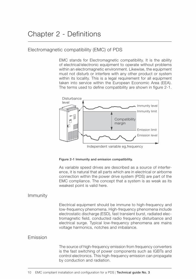
EMC stands for Electromagnetic compatibility. It is the ability of electrical/electronic equipment to operate without problems within an electromagnetic environment. Likewise, the equipment must not disturb or interfere with any other product or system within its locality. This is a legal requirement for all equipment taken into service within the European Economic Area ( EEA). The terms used to define compatibility are shown in figure 2-1.
Figure 2-1 Immunity and emission compatibility.
As variable speed drives are described as a source of interfer-ence, it is natural that all parts which are in electrical or airborne connection within the power drive system (PDS) are part of the EMC compliance. The concept that a system is as weak as its weakest point is valid here.
Immunity
Electrical equipment should be immune to high-frequency and low-frequency phenomena. High-frequency phenomena include electrostatic discharge (ESD), fast transient burst, radiated elec-tromagnetic field, conducted radio frequency disturbance and electrical surge. Typical low-frequency phenomena are mains voltage harmonics, notches and imbalance.
Emission
The source of high-frequency emission from frequency converters is the fast switching of power components such as IGBTs and control electronics. This high-frequency emission can propagate by conduction and radiation.

Technical guide No. 3 | EMC compliant installation and configuration for a PDS 11
Installation or part of installation
Power drive system PDS
Basic drive moduleBDM control, converter and protection
Feeding sectionauxiliaries and others
Motorand
sensors Drivenequipment
Complete drive module CDM
System control andsequencing
Power drive system
The parts of a variable speed drive controlling driven equip-ment as a part of an installation are described in EMC Product Standard EN 61800-3. A drive can be considered as a basic drive module (BDM) or complete drive module (CDM) according to the standard.
It is recommended that personnel responsible for design and installation have this standard available and be familiar with this standard. All standards are available from the national stand-ardization bodies.
Systems made by an OEM or panel builder can consist more or less of the PDS parts alone, or there can be many PDSs in a configuration.
The solutions described in this guide are used within the definition of power drive system, but the same solutions can, or in some cases, should, be extended to all installations. This guide gives principles and practical EMC examples, which can be applied to a user’s system.
Figure 2-2 Abb reviations used in drives.
Definitions

12 EMC compliant installation and configuration for a PDS | Technical guide No. 3
Types of equipment
The EMC Directive (2004/108/EC) defines equipment as any ap-paratus or fixed installation. As there are separate provisions for apparatus and fixed installations, it is important that the correct category of the equipment (PDM, CDM or BDM) is determined.
In technical-commercial classifications the following terminol-ogy is frequently used: components, sub-assemblies, finished appliances (ie, finished products), a combination of finished appliances (ie, a system), apparatus, fixed installations and equipment.
The key issue here is whether the item is meant for end users or not:
– if it is meant for end users, the EMC directive applies; – if it is meant for manufacturers or assemblers, the EMC
directive does not apply.
Components or sub-assemblies intended for incorporationinto an apparatus by the end users
A manufacturer may place components or sub-assemblies on the market, which are:
– for incorporation into an apparatus by the end-user, – available to end-users and likely to be used by them.
These components or sub-assemblies are to be considered as apparatus with regard to the application of the EMC. The instruc-tions for use accompanying the component or sub-assembly should include all relevant information, and should assume that adjustments or connections can be performed by an end user not aware of the EMC implications.
Some variable speed power drive products fall into this category, eg, a drive with enclosure and sold as a complete unit (CDM) to the end user who installs it into his own system. All provisions of the EMC Directive will apply ( CE mark, EC declaration of conformity and technical documentation).
Components or sub-assemblies intended for incorporationinto an apparatus by other manufacturers or assemblers
Components or sub-assemblies intended for incorporation into an apparatus or another sub-assembly by other manufacturers or assemblers are not considered to be “apparatus” and are therefore not covered by the EMC Directive. These components include resistors, cables, terminal blocks, etc.
Definitions

Technical guide No. 3 | EMC compliant installation and configuration for a PDS 13
Some variable speed power drive products fall into this category as well, eg, basic drive modules (BDM). These are meant to be assembled by a professional assembler (eg, panel builder or system manufacturer) into a cabinet not in the scope of delivery of the manufacturer of the BDM. According to the EMC Directive, the requirement for the BDM supplier is to provide instructions for installation and use.
Note:The manufacturer or assembler of the panel or system is respon-sible for the CE mark, the EC Declaration of Conformity, and the technical documentation.
Finished appliance
A finished appliance is any device or unit containing electrical and/or electronic components or sub-assemblies that delivers a function and has its own enclosure. Similarly to components, the interpretation “finished appliance” can be divided into two categories: it can be intended for end users, or for other manu-facturers or assemblers.
Finished appliance intended for end users
A finished appliance is considered as apparatus in the sense of the EMC Directive if it is intended for the end-user and thus has to fulfill all the applicable provisions of the Directive.
Variable speed power drive products that fall into this category are whole power drive systems (PDS) or complete drive mod-ules (CDM). In this case all provisions of the EMC Directive will apply (CE mark, EC Declaration of Conformity, and technical documentation). The drive product manufacturer is responsible for the CE mark, EC Declaration of Conformity, and technical documentation.
Finished appliance intended for other manufacturer or assembler
When the finished appliance is intended exclusively for an in-dustrial assembly operation for incorporation into other appa-ratus, it is not an apparatus in the sense of the EMC Directive and consequently the EMC Directive does not apply for such finished appliances.
The variable speed power drive products that fall into this cat-egory are basic drive modules (BDM). The approach is the same as for components or sub-assemblies when they are intended for incorporation into an apparatus by another manufacturer or assembler. Thus the manufacturer or assembler of the panel or system is responsible for all actions relating to the EMC Directive.
Definitions

14 EMC compliant installation and configuration for a PDS | Technical guide No. 3
Systems (combination of finished appliances)
A combination of several finished appliances which is combined, and/or designed and/or put together by the same party (ie, the system manufacturer) and is intended to be placed on the market for distribution as a single functional unit for an end- user and intended to be installed and operated together to perform a specific task.
All provisions of the EMC Directive, as defined for apparatus, apply to the combination as a whole. The variable speed power drive products that fall into this category are power drive systems (PDS). Thus the manufacturer of the PDS is responsible for all actions relating to the EMC Directive.
Apparatus
Apparatus means any finished appliance or combination thereof made commercially available (ie, placed on the market) as a single functional unit, intended for the end-user, and liable to generate electromagnetic disturbance, or the performance of which is liable to be affected by such disturbance.
Fixed installation
A particular combination of several types of apparatus, equip-ment and/or components, which are assembled, installed and intended to be used permanently at a predefined location.
Equipment
Any apparatus or fixed installation
CE marking for EMC
Components or sub-assemblies intended for incorporation into an apparatus by the end users need to carry the CE marking for EMC.
Components or sub-assemblies intended for incorporation into an apparatus by another manufacturer or assembler do not need to carry the CE marking for EMC.Note: The products may carry the CE marking for other direc-tives than EMC.
Definitions

Technical guide No. 3 | EMC compliant installation and configuration for a PDS 15
Medium voltage network
Point of measurement for conducted emission1st environment
Equipment PDS
Public low-voltage network Industrial low-voltage network
Point of measurement2nd environment
Apparatus and systems must be CE marked.
Fixed installations are required to satisfy various parts of the Directives, but are not required to be CE marked.
Figure 2-3 The CE mark.
Installation environments
The PDSs can be connected to either industrial or public power distribution networks. The environment class depends on the way the PDS is connected to power supply. The environment classes are first and second environment according to the EN61800-3 standard.
First environment
“The first environment includes domestic premises. It also in-cludes establishments directly connected without intermediate transformer to a low-voltage power supply network which sup-plies buildings used for domestic purposes.”
Figure 2-4 Illustration of environment classes.
Definitions

16 EMC compliant installation and configuration for a PDS | Technical guide No. 3
Second environment
“The second environment includes all establishments other than those directly connected to a low-voltage power supply network which supplies buildings used for domestic purposes”.
EMC emission limits
The product standard EN 61800-3 divides PDSs into four cat-egories according to the intended use. In Europe, the standard takes precedence over all generic or product family EMC stand-ards previously applicable. Limits for certain conditions can be selected by using the flow chart shown in figure 2-5.
PDS of category C1
A PDS (or CDM) with rated voltage less than 1000 V and intended for use in the first environment. A PDS (or CDM) sold “as built” to the end user.
The PDS manufacturer is responsible for the EMC behavior of the PDS under specified conditions. Additional EMC measures are described in an easy-to-understand way and can be imple-mented by a layman.
When PDS/CDM is to be incorporated with another product, the resulting EMC behavior of that product is the responsibility of the assembler of the final product, by following the manufacturer’s recommendations and guidelines.
PDS of category C2
A PDS (or CDM/BDM) with rated voltage less than 1,000 V, which is neither a plug in device nor a movable device and is intended to be installed and commissioned only by a professional. A PDS (or CDM/BDM) sold to be incorporated into an apparatus, system or installation.
When a PDS/CDM/BDM is to be incorporated with another product, the resulting EMC behavior of that product is the re-sponsibility of the assembler of the final product.
PDS of category C3
A PDS (or CDM/BDM) with rated voltage less than 1,000 V, intended for use in the second environment. A PDS (or CDM/BDM) sold “as built” to the end user or in order to be incorporated into an apparatus, system or installation.
The PDS manufacturer is responsible for the EMC behavior of the PDS under specified conditions. Additional EMC measures are described in an easy-to-understand way and can be imple-mented by a layman.
Definitions

Technical guide No. 3 | EMC compliant installation and configuration for a PDS 17
When a PDS/CDM is to be incorporated with another product, the resulting EMC behavior of that product is the responsibility of the assembler of the final product, by following the manufac-turer’s recommendations and guidelines.
PDS of category C4
A PDS (or CDM/BDM) with rated voltage equal to or above 1,000 V, or rated current equal to or above 400 A, or intended for use in complex systems in the second environment. A PDS (or CDM/BDM) sold to be incorporated into an apparatus, system or installation.
Category C4 requirements include all other EMC requirements except for radio frequency emission. They are assessed only when it is installed in its intended location. Therefore a category C4 PDS is treated as a fixed installation, and thus has no re-quirement for an EC Declaration of Conformity or CE Marking.
The EMC directive requires the accompanying documentation to identify the fixed installation, its electromagnetic compatibility characteristics and the person responsible, and to indicate the precautions to be taken in order not to compromise the conform-ity of that installation.
In order to comply with the above requirements in the case of a category C4 PDS (or CDM/BDM), the user and the manufacturer shall agree on an EMC plan to meet the EMC requirements for the intended application. In this situation, the user defines the EMC characteristics of the environment including the whole installa-tion and the neighborhood. The PDS manufacturer shall provide information on typical emission levels and installation guidelines for the PDS to be installed. The resulting EMC behavior is the responsibility of the installer (eg, by following the EMC plan).
Where there are indications of non-compliance of the category C4 PDS after commissioning, the standard includes a procedure for measuring the emission limits outside the boundary of an installation.
Definitions

18 EMC compliant installation and configuration for a PDS | Technical guide No. 3
EN 61800-3EMC product standard for PDS
1st environment(public low-voltage network)
2nd environment(industrial network)
EMC plan
CONDUCTED
RADIATED
Disturbance
Figure 2-5 Emission limits for PDS.
Definitions

Technical guide No. 3 | EMC compliant installation and configuration for a PDS 19
Radiated emission
Supplynetwork
Conductedemission
Earth
Control
Process
Motorconnection
Motor
Chapter 3 - EMC solutions
General
The solutions used to fulfill immunity and both radiated and conducted emission requirements are described in this chapter.
Solutions for EMC compatibility
There are some basic principles which must be followed when designing and using drive systems incorporating AC drive prod-ucts. These same principles were used when these products were initially designed and constructed, where such issues as printed circuit board layout, mechanical design, wire routing, cable entries and other special points were all considered in great detail.
Emissions
The emissions can be classified into two types; conducted emis-sion and radiated emission. The disturbances can be emitted in various ways as shown in the following figure:
Figure 3-1 Emissions.
Conducted emission
Conducted disturbances can propagate to other equipment via all conductive parts including cabling, earthing and the metal frame of an enclosure.

20 EMC compliant installation and configuration for a PDS | Technical guide No. 3
Conductive emissions can be reduced in the following way:
– By RFI filtering for HF disturbances – Using ferrite rings in power connection points – Using an AC or DC choke (even meant against harmonics,
it reduce HF disturbances as well. – Using an LCL filter in the case of regenerative drives – Using a du/dt filter
Radiated emission
To be able to effectively prevent disturbance through the air, all parts of the power drive system should form a Faraday cage against radiated emissions. The installation of a PDS includes cabinets, auxiliary boxes, cabling, motors, etc.
Some methods for ensuring the continuity of the Faraday cage are listed as follows:
Enclosure
– The enclosure must have an unpainted non-corroding surface finish at every point where other plates, doors, etc. make contact.
– Unpainted metal-to-metal contacts shall be used throughout, with conductive gaskets, where appropriate.
– Use unpainted installation plates, bonded to a common earth point, ensuring all separate metal items are firmly bonded to achieve a single path to earth.
– Use conductive gaskets in doors and covers. Separate the radiative ie, “dirty” side from the “clean side” by metal covers and design.
– Holes in enclosure should be minimized.
Cabling and wiring
– Use special HF cable entries for high frequency earthing of power cable shields.
– Use conductive gaskets for HF earthing of control cable shield.
– Use shielded power and control cables. See product specific manuals.
– Allow no breaks in the cable shields. – Select shield connections with low impedance on the MHz
range. – Route power and control cables separately. – Use twisted pairs to avoid disturbances. – Use ferrite rings for disturbances, if necessary. – Select and route internal wires correctly. – See product specific manuals.
EMC solutions

Technical guide No. 3 | EMC compliant installation and configuration for a PDS 21
Rectifi er
RFIfilter
Dirty side
Clean side
Installation
– Auxiliaries used with complete drive modules (CDMs) should be CE marked products conforming to both the EMC & Low Voltage Directives, NOT ONLY to the LV directive, unless they are intended for incorporation into an apparatus by another manufacturer or assembler.
– Selection and installation of accessories in accordance with manufacturers’ instructions.
– For wall-mounted units, strip the sheathing of a motor cable back far enough to expose the copper wire screen so that the screen can be twisted into a pigtail. Keep the pigtail short and connect it to the ground.
– For cabinet models, lead the cables into the inside of the enclosure. Apply 360° grounding of the cable shield at the entry into the cabinet. See product specific manuals.
– 360° earthing at motor end. See motor manuals.
Clean and dirty side
The circuit before the point where the supply power is connected to the CDM and where the filtering starts is referred to as the clean side. The parts of the BDM that can cause disturbances are described as the dirty side.
Enclosed wall-mounted drives are designed so that the circuit followed by the output connection is the only dirty part. That is the case if the installation instructions of the drive are followed.
To be able to keep the clean side “clean”, the dirty parts are separated into a Faraday cage. This can be done either with separation plates or with cabling.
Figure 3-2 “Clean” and “dirty” sides of the BDM.
EMC solutions

22 EMC compliant installation and configuration for a PDS | Technical guide No. 3
Line Line
When using separation plates, the rules for enclosure holes are applicable (see Holes in enclosures section later in this chapter).
When the Faraday cage is formed by cabling, the rules for ca-bling must be applied (see sections on cabling and wiring in this chapter and follow the product specific instructions for the drive).
The use of additional components, eg, contactors, isolators, fuses, etc. in some cases makes it difficult to keep the clean and the dirty side separate.
This can happen when contactors or switches are used in circuits to change over from clean to dirty side (eg, by-pass).
Some examples of solutions are described in chapter 4, Practi-cal examples.
RFI filtering
RFI filters are used to attenuate conducted disturbances in a line connecting point where the filter leads the disturbances to earth.
Output filters attenuate disturbances at the output of a PDS. Eg, du/dt and common mode filters help somewhat, even if they have not been designed for RFI.
Filters cannot be used in a floating network (IT-network) where there is high impedance or no physical connection between the phases and the earth.
Figure 3-3 Example of filtering integrated in drive module.
Figure 3-3 shows an example of integral, distributed filtering. Some drive products need a separate filter (see product specific instructions).
EMC solutions

Technical guide No. 3 | EMC compliant installation and configuration for a PDS 23
Selecting the RFI filter
An RFI filter is selected to attenuate the conducted disturbances. It is not possible to compare the disturbances measured from a source, and the insertion loss for a filter, as the measurement base for the two items of information will not correspond.
It is always necessary to test a filter in conjunction with the source of disturbance to ensure adequate attenuation and to meet applicable emission limits.
Installation of the RFI filter
Reliable HF/low impedance connections are essential to ensure proper functioning of the filter, therefore the following instructions are to be followed. – The filter shall be assembled on a metal plate with unpainted
connection points all in accordance with the filter manufac-turer’s instructions.
– The orientation of the filter must be such that it provides enough distance between the input and output wiring of the filter in order to prevent cross-coupling between the clean and dirty side.
– The length of the cable between the filter and the drive must be minimized.
– The input cable of the filter shall be separated from the cable which connects the filter to the drive
– The input cable of the filter shall be separated from the mo-tor cable
Selection of a secondary enclosure
Where the BDM is to be installed, (eg, an IP00 open chassis converter), or if additional components are to be connected to the dirty side of an otherwise compliant unit, it is always neces-sary to provide an EMC enclosure.
For enclosed chassis modules where the motor connections are made directly to the converter output terminals and all the internal shielding parts are fitted, there are no requirements for special enclosures.
If drives are fitted with output switching devices, for example, then an EMC enclosure will be needed, as the integral Faraday cage will no longer apply.
As a reminder, EMC is only one part of enclosure selection. The enclosure is sized according to several criteria:
– Safety – Degree of protection (IP rating)
EMC solutions
24 EMC compliant installation and configuration for a PDS | Technical guide No. 3
FARADAY CAGE
Unpainted backplates
Enough locksat the door
Gland / bottomplates
Conductivesleeves
Limited hole size
Conductivesealingat the door
Conductivegasket forcontrol cables
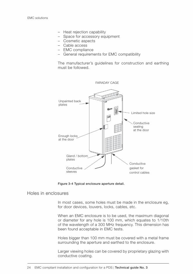
– Heat rejection capability – Space for accessory equipment – Cosmetic aspects – Cable access – EMC compliance – General requirements for EMC compatibility
The manufacturer’s guidelines for construction and earthing must be followed.
Figure 3-4 Typical enclosure aperture detail.
Holes in enclosures
In most cases, some holes must be made in the enclosure eg, for door devices, louvers, locks, cables, etc.
When an EMC enclosure is to be used, the maximum diagonal or diameter for any hole is 100 mm, which equates to 1/10th of the wavelength of a 300 MHz frequency. This dimension has been found acceptable in EMC tests.
Holes bigger than 100 mm must be covered with a metal frame surrounding the aperture and earthed to the enclosure.
Larger viewing holes can be covered by proprietary glazing with conductive coating.
EMC solutions

Technical guide No. 3 | EMC compliant installation and configuration for a PDS 25
Maximum size 72x72 mminstrument
Twisted pair
<100 mm
Install locks tounpainted door
Check that there is no holes >100 mm
Metal cover forholes >100 mm
Glazing must be connected to non-painted metal surrounds with conductive double-sided tape or conductive gasket.
Figure 3-5 Essential points of power connections.
360° HF earthing
360° HF earthing should be done everywhere where cables enter the drive enclosure, auxiliary connection box or motor. There are different ways to implement the HF earthing. The solutions used in ABB’s CDM/BDM products are described here.
HF earthing with cable glands
The cable glands, which are specially designed for 360° HF earthing, are suitable for power cables with a diameter less than 50 mm.
Cable glands are not normally used for control cables due to the fact that the distance from the control connections to the cable glands is often too long for reliable HF earthing. If the glands are used with control cables, the cable shielding must continue as near to the control connections as possible. Only the outer insulation of cable should be removed to expose the cable screen for the length of the cable gland.
To get the best possible result from HF earthing, the cable shield-ing should be covered with a conductive tape. The tape must cover the whole surface of the shielding, including pigtail, and should be tightly pressed with fingers after every single turn.
EMC solutions

26 EMC compliant installation and configuration for a PDS | Technical guide No. 3
SUPPLY CABLE MOTOR CABLE
As short unshielded wires as possible
Cable shielding covered with conductive tape
EMC cable gland
Clamping nut
CableContinuity of faraday cage
Short pigtail
Unpainted gland plate
Conductive shielding & compression seal
Short pigtail
Note conductive tape on the cable shielding
Conductive sleeve
Cable
Continuity offaraday cage
Unpainted gland plate with collars
Unpainted bottom plate
Figure 3-6 Essential points of power connections.
HF earthing with conductive sleeve
360° HF earthing in power cable entries can be done by using a conductive sleeve around the cable shielding. The sleeve is connected to the Faraday cage by tightening it to the specially designed collar in the gland plate.
Figure 3-7 360° earthing with conductive sleeve.
EMC solutions

Technical guide No. 3 | EMC compliant installation and configuration for a PDS 27
Above cable clamp, cover bare shield with insulating tape
Cable clamp on bare shield
Motor cable Braking resistor cable
0.5...0.6 Nm (4.4...5.3 lbf in)
1.5 Nm (13 lbf in)
1.5 Nm (13 lbf in)
Figure 3-8 360° earthing with clamping of cable shield.
The advantage of this solution is that the same sleeve can be used for cables with different diameters.
The cable can be mechanically supported by clamps, and a specific cable gland is not required.
Note that the sleeve does not act as a strain relief clamp.
360° earthing at motor end
The continuity of the Faraday cage at the motor end must be ensured by the same methods as in cabinet entry, namely:
– Faraday cage and IP55 degree of protection. This includes: – Cable gland providing galvanic contact must be used for
clamping the cable. – Cable shielding should be sealed with conductive tape. – Conductive gaskets should be used for sealing both the
cable gland plate and the terminal box cover – Note: Please check availability from motor manufacturer. It is
common that this is one option for the motor – Pigtails of earthing conductors must be as short as possible.
EMC solutions

28 EMC compliant installation and configuration for a PDS | Technical guide No. 3
Cable shielding coveredwith conductive tape
Short pigtail
EMC cable gland
Continuity offaraday cage
Conductive gasket
Figure 3-9 shows a Faraday cage solution at the motor end.
For motors that are not totally enclosed, such as in cooling form IC01, IC06, etc. the continuity of the Faraday cage must be ensured in the same manner as for the converter enclosure.
Figure 3-9 Essential points in motor cabling.
Conductive gaskets with control cables
The 360° HF earthing for control cables can be done with con-ductive gaskets. In this method the shielded control cable is led through two gaskets and pressed tightly together, as shown in figure 3-10.
When gaskets are mounted at a gland plate, the cable shielding must continue as near to the control connections as possible. In this case the outer insulation of the cable should be removed to allow connection to the shield for the length of the gasket transit.
The shielding should be covered with conductive tape.
The best HF earthing is achieved if gaskets are mounted as near to the control connections as possible.
The gaskets must be installed to connect with the earthed un-painted surfaces of the gland plate to which they are mounted.
All connection tails should be as short as possible, and twisted in pairs where appropriate. The cable shield should be earthed to the connection end by a short pigtail.
The hole size in a gland plate required by these gaskets is typi-cally 200 x 50 mm.
EMC solutions

Technical guide No. 3 | EMC compliant installation and configuration for a PDS 29
As short as possible
Shi
eld Control
connections
Wrap copper tape around the stripped part of the cable under the clamp. Be careful.Do not cut the grounding wire. Clamp as close to the terminals as possible.
Figure 3-10 Essential points for control cabling transit.
Installation of accessories
The variety of accessories that can be installed is so large that only basic principles for selection and installation can be given for them.
Accessories can, however, be divided into two categories de-pending on how immune/sensitive they are. The protected device in this context means its ability to keep the Faraday cage closed. It is therefore recommended to use metal enclosed/shielded devices wherever such devices are available.
The rules for holes in the enclosure must be applied if there are devices forming a bridge between the clean side and the dirty side, which can be disturbed.
Typical open devices are fuses, switch fuses, contactors etc., which do not have a metal covering around them.
In general, such devices cannot be installed into the clean side without protective metallic shielding plates. The rules for holes in the enclosure must then be applied.
Some examples of protected and open devices are given in the chapter Practical examples.
Internal wiring
There are some basic rules for internal wiring: – Always keep clean and dirty side cables separate and shielded
from one another. – Internal clean power connections with integrally filtered drive
units, eg, from contactor to converter input, do not require shielded cables but may require de-coupling ferrite rings where they enter the converter input.
EMC solutions

30 EMC compliant installation and configuration for a PDS | Technical guide No. 3
CABINETDEVICE
AnalogSignal (V)AnalogSignal (mA)
POTENTIAL FREE DIG. OUTPUT
DO
DO
DOOR DEVICE Twist thesepairs of pairs
Use shielded cables for Analog mA signalsFor earthing rules see part Control Cabing
Don’t mix differentsignal levels
Diode for DC relay
Don’t mix different signal levels
RC filter orvaristor forAC relay
CLEAN SIDE
DIRTY SIDE
Avoid parallel running with control wiresCross in 90°
Keep these separate (see figure 3-11)
Avoid parallel running with control wiresCross in 90° angle
SUPPLYCONNECTION
MOTOROUTPUT
Twist the pairsup to terminals
+24 V d.c.GND
NCCommonNO
NCCommonNO
NCCommonNO
RELAY OUTPUTS(pot. free)
ANALOG SIGNALS
DIGITAL INPUTSDI1
DI3
DI6+24 V d.c.+24 V d.c.GND
+10 VGNDAI1+AI1-
AI3+AI3-AO1+AO1-AO2+AO2-
(0...10 V)
(4...20 mA)
230 V a.cN
U1V1W1U2V2W2
– Use twisted pair wires wherever possible. – Use shielded twisted pairs for signal level outward and return
wires exiting from the overall enclosure. – Avoid mixing pairs with different signal types eg, – 110 V AC, 230 V AC, 24 V DC, analogue, digital. – Run wires along the metal surface and avoid wires hanging
in free air, which can become an antenna. – If plastic trunking is used, secure it directly to installation
plates or the framework. Do not allow spans over free air, which could form an antenna.
– Keep power and control wiring separate. – Use galvanically isolated (potential free) signals. – Keep wires twisted as near the terminal as possible. – Keep pigtails as short as possible. – Earthing connections should be as short as possible in flat
strip, multi-stranded or braided flexible conductors for low RFI impedance.
Figure 3-11 Principles of wiring inside CDM.
EMC solutions

Technical guide No. 3 | EMC compliant installation and configuration for a PDS 31
Product specific manual
Motor cable
Mains cable
Signal / control cables
Control cables and cabling
The control cabling is a part of the Faraday cage as described in the section Conductive gaskets with control cables.
In addition to correct HF earthing there are some basic rules for control cabling:
– Always use shielded twisted pair cables: – double-shielded cable for analogue signals – single-shielded for other signals is acceptable, but double-
shielded cable is recommended. – Don’t run 110/230 V signals in the same cable as lower signal
level cables. – Keep twisted pairs individual for each signal. – Earth directly on the frequency converter side.
If instructions for the device at the other end of the cable specify earthing at that end, earth the inner shields at the end of the more sensitive device and the outer shield at the other end.
Route signal cables according to figure 3-12 whenever possible, and follow instructions given by the product specific manuals.
Figure 3-12 Routing principles of control cables.
There is more about control cabling in the “Grounding and cabling of the drive system” documents” and in product specific manuals.
EMC solutions
32 EMC compliant installation and configuration for a PDS | Technical guide No. 3
Power cables
As the cables are part of the PDS they are also part of the Faraday cage. To be able to meet the EMC requirements, power cables with good shielding effectiveness must be used.
The purpose of the shield is to reduce radiated emission.
In order to be efficient, the shield must have good conductiv-ity and cover most of the cable surface. If the cable shield is used as protective earthing, the shield cross area (or equivalent conductivity) must be at least 50 percent of the cross sectional area of the phase conductor.
The product specific manuals describe some cable types that can be used in mains supply and motor output.
If such types are not available locally, and because cable manu-facturers have several different shield constructions, the types can be evaluated by the transfer impedance of the cable.
The transfer impedance describes the shielding effectiveness of the cable. It is commonly used with communication cables.
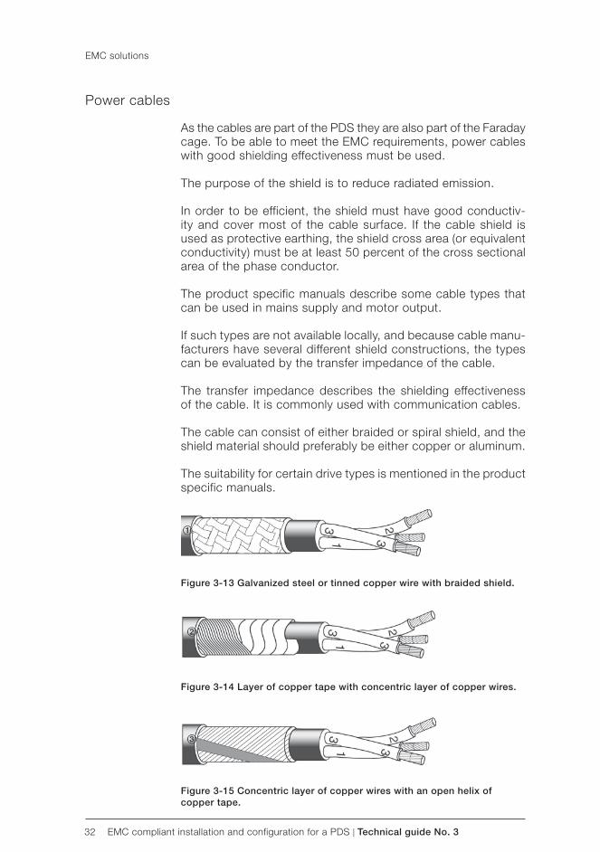
The cable can consist of either braided or spiral shield, and the shield material should preferably be either copper or aluminum.
The suitability for certain drive types is mentioned in the product specific manuals.
Figure 3-13 Galvanized steel or tinned copper wire with braided shield.
Figure 3-14 Layer of copper tape with concentric layer of copper wires.
Figure 3-15 Concentric layer of copper wires with an open helix of copper tape.
EMC solutions

Technical guide No. 3 | EMC compliant installation and configuration for a PDS 33
Transferimpedance(mOhm/m)
Non-recommended cable
Galvanised steel or tinnedcopper wire with braided shield (fig. 3-12)
Layer of copper tape withconcentric layer of copper wires (fig. 3.13)
Corrugated shield
Frequency (MHz)
Transfer impedance
To meet the requirements for radiated emission, the transfer impedance must be less than 100 mΩ/m in the frequency range up to 100 MHz. The highest shielding effectiveness is achieved with a metal conduit or corrugated aluminum shield. Figure3-16 shows typical transfer impedance values of different cable constructions. The longer the cable run, the lower the transfer impedance required.
Figure 3-16 Transfer impedance for power cables.
Use of ferrite rings
In particular cases, due to high emission levels, common mode inductors can be used in signal cables to avoid interfacing prob-lems between different systems.
Common mode disturbances can be suppressed by wiring conductors through the common mode inductor ferrite core (figure 3-17).
The ferrite core increases inductance of conductors and mutual inductance, so common mode disturbance signals above a cer-tain frequency are suppressed. An ideal common mode inductor does not suppress a differential mode signal.
EMC solutions

34 EMC compliant installation and configuration for a PDS | Technical guide No. 3
Figure 3-17 Ferrite ring in signal wire.
The inductance (ie, the ability to suppress HF disturbances) can be increased by multiple turns of the signal wire.
When using a ferrite ring with power cable, all phase conductors should be led through the ring. The shielding and possible earth wire must be wired outside the ring to keep the common mode inductor effect. With power cables it is not normally possible to make multiple turns through the ring. The inductance can be increased by using several successive rings.
If for any reasons the installation instructions cannot be followed and therefore additional ferrites or filters are added afterwards, it is recommended that measurements be made to show con-formance.
EMC solutions

Technical guide No. 3 | EMC compliant installation and configuration for a PDS 35
DriveINPUT OUTPUT
External brakeresistor
Motor
Chapter 4 - Practical examples
Simple installation
Most simple installations of PDS include three cables only: sup-ply cable, motor cable and cable for brake resistor as shown in Figure 4-1.
Notes:1), 2) If shielded cable is used, use a separate PE cable (1) or a cable with a grounding conductor (2) if the conductivity of the input cable shield is < 50 percent of the conductivity of the phase conductor. Ground the other end of the input cable shield or PE conductor at the distribution board. 3) 360 degrees grounding recommended if shielded cable4) 360 degrees grounding required5) Use a separate grounding cable if the conductivity of the cable shield is < 50 percent of the conductivity of the phase conductor and there is no symmetrically constructed grounding conductor in the cable.
Figure 4-1 Most simple PDS installation.
Typical installation
Shielded cables are shown interconnecting the primary parts, ensuring attenuation of radiated emissions. The supply is made through the RFI filter.
The Faraday cage is earthed and all the emissions are drained to earth.
In the case shown in figure 4-2, the cabinet is not required to be EMC proof, because connections are made directly in an EMC compliant frequency converter.

36 EMC compliant installation and configuration for a PDS | Technical guide No. 3
Transformer
360° HF earthing
Shielded cable
Metalframecabinet
CabinetUnpaintedmountingplate
Drive
RFI
FILTER
Metal box
Metal box
Rectifier
BRAKERESISTOR
BRAKECHOPPER
For connection details, seeProduct Specific Manualfor chopper and resistor.
For more details, see sectionon 360° EARTHING ATMOTOR END
CONTROL
1) Short pigtailto PE, both common
and pair screen2) 360° HF grounding3) For rules, see part
CONTROLCABLING
Motor output
Figure 4-2 Typical PDS configuration.
Example of by-pass system <100 kVA
In this case it is difficult to ensure that no cross coupling occurs between the dirty side of the converter and the clean side above the direct on line (DOL) contactor. Contactors are not RFI barri-ers, and the coil circuits are also vulnerable.
A suitable RFI filter at the supply input connections would require to be able to pass the DOL starting current, which can be six to seven times the normal full load current, and would be greatly oversized for normal running, which makes it difficult to design. Ferrite cores used in the feeds to the contactor will help attenu-ate the coupled noise as shown in figure 4-3.
Practical examples

Technical guide No. 3 | EMC compliant installation and configuration for a PDS 37
Transformer 360° HF earthing
Shielded cable
RADIATIVE ie, DIRTY side
Cabinet 1supplyconnection
The ferrite in the DOL circuit isfor cross coupling of clean anddirty side Motor Output of PDS
Ferrite
Metal box
BY-PASSCONTROL
CONTROLRELAYSOR PLC
Contactor
Motoroutput
Metal box
Safety sw.
For more details, see360° MOTOR EARTHING
1) Short pigtailtp PE, both common
and pair shield3) For rules, see part
CONTROLCABLING
Isolator
Isolator
RFIFILTER
Contactor
Control
Metal boxDRIVEMODULE
Metalframecabinet
Practical examples
Figure 4-3 Basic scheme with by-pass.
Typical example of 12-pulse drive
In this case a 12-pulse rectifier is an IT system, unearthed due to the delta winding; therefore any filter in the line must be at the primary side of the phase shift transformer.
Experience has shown that, in this case, with short connections to the busbars, the earth shield between the transformer windings is not quite adequate for conducted emissions attenuation for use in the first environment. Therefore an RFI filter may be needed at the primary side of the transformer for EMC compliance. An RFI filter is not normally needed for the second environment.

38 EMC compliant installation and configuration for a PDS | Technical guide No. 3
360° HF grounding
Shielded cable
Shielded control cables
Control & displayEnclosure, with segregation
Low voltage supply
Point ofmeasurement
Shielded motorcables
RFIFILTER
Commonearth
DRAIN FOR EMISSIONS
Incoming switchfuse contactor
Phase shifttransformer(if integrated)
Rectifiers Inverter Output choke(Ferrite)
Commonearth
DRAIN FOR EMISSIONS
Incoming switchfuse contactor
Phase shifttransformer(if integrated)
Rectifiers Inverter Output choke(Ferrite)
360° HF grounding
Shielded cable
Shielded control cables
Control & display Shielded motorcables
Enclosure,with segregation
Point ofmeasurement
Medium or high voltage supply
For equipment fed from an IT system, a similar procedure can be used. An isolating transformer allows the PDS to be earthed and to use a suitable filter, for use in the first environment. The point of coupling is at a medium voltage and emissions may be considered at the next low voltage point of coupling in the system. The level of emissions should correspond to those for the appropriate environment. For definitions, see the Installation environments section in chapter 2.
Note: All equipment inside must be enclosedFigure 4-4 12-pulse converter system fed at LV.
Figure 4-5 12-pulse converter system fed at LV (CDM, transformer and switch fuse have separate housing).
Practical examples

Technical guide No. 3 | EMC compliant installation and configuration for a PDS 39
Example of EMC plan
This is a form for making an EMC plan where the user and the manufacturer analyze the installation and define the measures to be taken to achieve electromagnetic compatibility. The plan defines the responsibilities of the manufacturer, the installer and the user of the drive. All these parties establish the plan jointly. Fill in and answer the questions below.
Step 1: Name the parties
Manufacturer/supplier ABB Oy, Drives
End user ABC Paper company
Order no. 123456789
Type of facility(eg, chemical factory, paper machine)
Paper machine PM3
Application(eg, pump. fan, conveyor)
Sectional drive system
Step 2: Collect power distribution and earthing data
Powerdistribution
Point of coupling: identification code for distribution panel, switchgear or trans-former
Transformerc T11
Type of distribution system TN-C,TN-S TT,IT
Earth bus How and where bonded?At supply transformer T11
Practical examples

40 EMC compliant installation and configuration for a PDS | Technical guide No. 3
Step 3: Collect EMC data (high frequency range, only)
RFI Sensitive equiment in the facility
Any equipment in the building or near installation location sensitive to RF disturbances (eg, process con-trol and measurement, data buses, computers, remote control, etc.)? Describe.
Yes / No
Data handling unit for process control
Approximate distance from PDS and cabling of PDS
5 metres
Most likely coupling path for disturbance
Conducted Radiated
RFI Sensitive equipment outside the facility
Any broadcast or communications receiver antennas visible or near the facility (eg, radar, radio/TV broad-cast, amateur, microwave or other)? Describe.
Yes / No
Frequency Hz
Distances from the antenna metres
Step 4: Define the installation rules
Follow the installation rules given in the hardware manual of the drive.
Assess the following items and describe the solutions.
EMCEffectiveness
Items to be considered
Cabling - cabling according to ABB cabling standards andguidelines (cable types, installation, separate trays etc.)
- earthing according to ABB instructions(earthing of trays etc.)
Dedicatedtransformer
- dedicated supply transformer T11 with static EMC-shield
Signature(s) by person(s) responsible for EMC
Date 26/09/2007Signature(s)Joe Smith
Practical examples

Technical guide No. 3 | EMC compliant installation and configuration for a PDS 41
Chapter 5 - Bibliography
Various texts are referred to in this guide. They are recommended further reading to assist in achieving compliant installations:
EN 61800-3, Adjustable speed electrical power drive systems - part 3, EMC product standard including specific test (published by CENELEC, Brussels, Belgium and National Standards organi-zations in EU member countries).
EN 61800-3:2004
Interference Free Electronics by Dr. Sten Benda (published by ABB Industry Ab, Västerås, Sweden)
Technical guide No. 2 - EU Council Directives and adjustable speed electrical power drive systems, code 3AFE61253980 (published by ABB Oy Drives, Helsinki, Finland)
Grounding and cabling of the drive system, code 3AFY61201998 (published by ABB Oy Drives, Helsinki, Finland)

42 EMC compliant installation and configuration for a PDS | Technical guide No. 3
Chapter 6 - Index
Symbols12-pulse rectifier 37
Aantenna 30apparatus 7, 12, 13, 14appliance 12, 13, 14assembler 7, 12, 13, 14, 16, 17, 21
Bbasic drive module 8, 11
Ccabinet 13, 20, 21, 27, 35cable gland 25, 27CE mark 7, 12, 14, 15CENELEC 41complete drive module 8, 11components 12conducted radio frequency distur-bance 10conduction 10control electronics 10converter 23, 28, 29, 35, 36, 38cross coupling 36customer 8
Ddelta winding 37DOL 36double shielded cable 31drive 7, 8, 9, 11, 12, 13, 14, 19, 20, 21, 22, 25, 29, 31, 32, 37, 39, 40
EEEA 7, 10electrical surge 10Electromagnetic compatibility 10electromagnetic disturbance 14electromagnetic environment 10electrostatic discharge 10enclosure 12, 17, 18, 19, 20, 23, 24, 26, 28, 38end user 12, 13, 16, 39environment 10, 15, 16, 37equipment 7, 8, 10, 11, 12, 14, 19, 24, 38, 40
FFaraday cage 20, 21, 22, 23, 26, 27, 28, 29, 31, 32fast transient burst 10ferrite core 33ferrite ring 33, 34finished appliance 12, 13, 14first environment 15, 16, 37fixed installation 12, 14, 15, 17frequency converter 31, 35fuse 38
Ggasket 22, 23, 25gland plate 25, 26, 27
Hharmonics 10high-frequency emission 10high-frequency phenomena 10
Iimbalance 10isolating transformer 38IT system 37, 38
Llow-frequency phenomena 10low-voltage network 15Low Voltage Directive 7
MMachinery Directive 7manufacturer 7, 8, 12, 13, 14, 16,17, 21, 23, 24, 27medium voltage network 15motor 19, 22, 25, 27, 31
Nnotches 10
Ooriginal equipment manufacturers 7
Pphase shift transformer 37pigtail 25, 27, 28plastic trunking 30point of coupling 38power components 10power distribution networks 15power drive system 1, 3, 10, 11power supply network 15, 16
Rradiated electromagnetic field 10radiation 10RFI filter 20, 23, 35, 37
Ssecond environment 16, 17single functional unit 8, 14strain relief clamp 27sub-assembly 12system 7, 8, 9, 10, 11, 12, 13, 14, 16, 17, 19, 20, 31, 33, 36, 37, 38, 39, 41
Ttechnical documentation 7, 8, 12, 13transformer 15, 37, 38twisted pair 24, 30, 31
Uunrestricted 15user 7, 8, 11, 12, 15, 16


3AFE
6134
8280
RE
V D
EN
8.6
.201
2 #1
6342
Contact us
© Copyright 2012 ABB. All rights reserved. Specifications subject to change without notice.
For more information contact your local ABB representative or visit:
www.abb.com/driveswww.abb.com/drivespartners