Embed Size (px)
Citation preview

Technical Guidance: Screening assessment for biomass boilers
Report to the Department of Environment, Food and Rural Affairs and the Devolved Administrations ED48673005/R2655 Issue Number 1 July 2008


Technical Guidance: Screening assessment for biomass boilers AEA/ED48673005/R2655 Issue 1
AEA Energy & Environment iii
Title Technical Guidance:
Screening assessment for biomass boilers Customer Department for Environment, Food and Rural Affairs and the Devolved
Administrations Customer reference Confidentiality, copyright and reproduction
This report is the Copyright of AEA Technology plc and has been prepared by AEA Technology plc under contract to the Department for Environment, Food and Rural Affairs. The contents of this report may not be reproduced in whole or in part, nor passed to any organisation or person without the specific prior written permission of the Commercial Manager, AEA Technology plc. AEA Technology plc accepts no liability whatsoever to any third party for any loss or damage arising from any interpretation or use of the information contained in this report, or reliance on any views expressed therein.
File reference Reference number AEA/ED48673005/R2655- Issue 1 AEA Energy & Environment
The Gemini Building Fermi Avenue
Harwell International Business Centre Didcot OX11 0QR t: 0870 190 6401 f: 0870 190 6318 AEA Energy & Environment is a business name of AEA Technology plc AEA Energy & Environment is certificated to ISO9001
and ISO14001 Author Name John Abbott Approved by Name Alison Loader Signature Date 4 July 2008
Technical Guidance: Screening assessment for biomass boilers AEA/ED48673005/R2655 Issue 1
iv AEA Energy & Environment

Technical Guidance: Screening assessment for biomass boilers AEA/ED48673005/R2655 Issue 1
AEA Energy & Environment v
Executive summary
The European Union and the United Kingdom Government have set greenhouse gas emission reduction and renewable energy usage targets. The use of biomass to generate energy offers significant potential environmental advantages for the reduction in emissions of greenhouse gases. The UK Energy White Paper, released in May 2007, has acknowledged the role of biomass and its potential contribution to renewable energy in the UK. However, there are concerns, particularly in London, that a significant increase in biomass combustion, particularly of wood fuel, could have a detrimental impact on particulate matter, PM10 and oxides of nitrogen concentrations. This is a particularly sensitive issue in areas where Air Quality Management Areas (AQMAs) are in force. Local authorities are required to review and assess air quality in their areas against objectives set out in the Government’s Air Quality Strategy. Local authorities are then required to declare an AQMA where it is likely that the objectives will not be achieved. Technical Guidance LAQM.TG(03) provides advice on how to assess air quality. The Air Quality Strategy was revised in July 2007 and new Technical Guidance is consequently being prepared in order to support local authorities in their duties. This report provides background information on methods of assessing the impact of biomass combustion appliances on air quality proposed for inclusion in the new Technical Guidance.

Technical Guidance: Screening assessment for biomass boilers AEA/ED48673005/R2655 Issue 1
vi AEA Energy & Environment
Table of contents
1 Introduction 1
2 Air quality objectives 3
3 Individual installations 5 3.1 Introduction 5 3.2 Dispersion modelling 5 3.3 Procedures 11 3.4 An example 14
4 Combined impacts 16 4.1 Introduction 16 4.2 Dispersion modelling 16 4.3 Estimating emissions 16 4.4 Method 19 4.5 Example 21
Appendices Appendix 1 Emission factors for solid fuel combustion

Technical Guidance: Screening assessment for biomass boilers AEA/ED48673005/R2655 Issue 1
AEA Energy & Environment vii


Technical Guidance: Screening assessment for biomass boilers AEA/ED48673005/R2655 Issue 1
AEA Energy & Environment 1
1 Introduction The European Union and the United Kingdom Government have set greenhouse gas emission reduction and renewable energy usage targets. The use of biomass to generate energy offers significant potential environmental advantages for the reduction in emissions of greenhouse gases. The UK Energy White Paper, released in May 2007, has acknowledged the role of biomass and its potential contribution to renewable energy in the UK. However, there are concerns, particularly in London, that a significant increase in biomass combustion, particularly of wood fuel, could have a detrimental impact on particulate matter, PM10 and oxides of nitrogen concentrations. This is a particularly sensitive issue in areas where Air Quality Management Areas (AQMAs) are in force. Local authorities are required to review and assess air quality in their areas against objectives set out in the Government’s Air Quality Strategy. Local authorities are then required to declare an AQMA where it is likely that the objectives will not be achieved. Technical Guidance LAQM.TG(03) provides advice on how to assess air quality. The Air Quality Strategy was revised in July 2007 and new Technical Guidance is consequently being prepared in order to support local authorities in their duties. This report provides background information on methods of assessing the impact of biomass combustion appliances on air quality proposed for inclusion in the new Technical Guidance. The Air Quality Strategy objectives are set out in Section 2. The report considers biomass combustion for:
• Domestic heating; • Service sector heating (commercial offices, communication and transport, education,
government, health, hotel and catering, retail, sport and leisure, warehouses); • Industrial combustion<20MW net thermal input (process heating, steam generation, electricity
generation and combined heat and power). Larger plant is regulated under the Pollution Prevention and Control (PPC) regime and is not considered here. Local authorities need to consider:
• whether each separate installation will lead to a local exceedence of the air quality objectives; • whether several installations will combine to cause an exceedence of air quality objectives
over a wider area. The Air Quality Strategy objectives are set out in Section 2. Methods for assessing the local impact of individual installations are presented in Section 3. The methods consider whether the discharge stack is sufficiently tall to disperse the emitted pollutants. The methods cover service sector heating and industrial combustion. The height of chimney stacks for domestic appliances with less than 50 kW thermal input is covered by the Building Regulations. Methods for assessing the combined impact of multiple installations are presented in Section 4. The methods presented in Sections 3 and 4 are intended to provide an initial screening assessment to determine whether there is a risk of exceeding the objectives. The screening assessment is intended to provide a conservative overestimate of the potential impacts. More detailed assessment is required where the screening methods indicate that there is a risk of exceeding the objectives. The PPC regime covers a wide range of processes, including various combustion activities with less than 20 MW thermal input. The screening methods presented here are not sufficient on their own to meet the requirements of the PPC regime. The screening methods set out in this report are intended to assess whether there is a risk that the air quality objectives will not be met. When considering planning applications for new developments, local

Technical Guidance: Screening assessment for biomass boilers AEA/ED48673005/R2655 Issue 1
2 AEA Energy & Environment
authorities may wish to impose more stringent limits on emissions in order to further protect the health of members of the public or to allow headroom for other future developments in the area.

Technical Guidance: Screening assessment for biomass boilers AEA/ED48673005/R2655 Issue 1
AEA Energy & Environment 3
2 Air quality objectives Local Authorities are required under the Environment Act to assess air quality in their areas from time to time against air quality objectives set out in the Air Quality Regulations (2000) and the Air Quality (Amendment) Regulations (2002). The objectives are set out in Table 2.1.
Table 2.1. Air quality objectives included in the Air Quality Regulations (2000) and Amendment Regulations (2002) for the purpose of Local Air Quality Management
Air Quality Objective Pollutant Concentration Measured as
Date to be achieved by
Benzene All authorities
16.25 µg m-3
Running annual mean
31.12.2003
Authorities in England and Wales only
5.00 µg m-3 Annual mean 31.12.2010
Northern Ireland only 3.25 µg m-3 Running annual mean 31.12.2010 1,3-Butadiene 2.25 µg m-3 Running annual mean 31.12.2003 Carbon monoxide Authorities in England, Wales and Northern Ireland only
10.0 mg m-3
Maximum daily running 8-hour mean
31.12.2003
Authorities in Scotland only 10.0 mg m-3 Running 8-hour mean 31.12.2003 Lead 0.5 µg m-3
0.25 µg m-3 Annual mean Annual mean
31.12.2004 31.12.2008
Nitrogen dioxide 200 µg m-3not to be exceeded more than 18 times a year 40 µg m-3
1 hour mean Annual mean
31.12.2005 31.12.2005
Particles (PM10) (gravimetric)b,c All authorities
50 µg m-3 not to be exceeded more than 35 times a year 40 µg m-3
24 hour mean Annual mean
31.12.2004 31.12.2004
Sulphur dioxide 350 µg m-3 not to be exceeded more than 24 times a year 125 µg m-3 not to be exceeded more than 3 times a year 266 µg m-3 not to be exceeded more than 35 times a year
1 hour mean 24 hour mean 15 minute mean
31.12.2004 31.12.2004 31.12.2005
b. Measured using the European gravimetric transfer standard sampler or equivalent. c. These 2010 Air Quality Objectives for PM10 apply in Scotland only, as set out in the Air Quality (Scotland) Amendment Regulations 2002. Local Authorities are required to declare an Air Quality Management Area where it is likely that these objectives will not be achieved and to prepare an Action Plan to set out the measures to be taken to achieve the objectives. The Air Quality Strategy for England, Scotland, Wales and Northern Ireland (2007) introduced two further objectives for PM2.5. These are a “cap” of 25 µg m-3 to be achieved by 2010 and an exposure reduction target of 15 % reduction in average concentrations at urban background locations. These PM2.5 objectives have not yet been set in Regulations.

Technical Guidance: Screening assessment for biomass boilers AEA/ED48673005/R2655 Issue 1
4 AEA Energy & Environment

Technical Guidance: Screening assessment for biomass boilers AEA/ED48673005/R2655 Issue 1
AEA Energy & Environment 5
3 Individual installations
3.1 Introduction Local Authorities require a simple tool for assessing whether a biomass combustion installation in the range 50 kW to 20 MW thermal will lead to pollutant concentrations exceeding the air quality objectives or will compromise the effectiveness of measures set out in their Action Plans. Defra provides Technical Guidance (LAQM.TG(03)) for Local Air Quality Management. The Technical Guidance provides some simple nomographs for assessing the air quality impact of industrial sources. It is expected that the nomographs will remain within the revised guidance and they will be applicable to larger biomass combustion installations. However, biomass burners in the range up to about 2MWth are outside the range of application of the Technical Guidance nomographs. Nomographs suitable for application to biomass combustion plant less than 2MWth are developed in this chapter. The Technical Guidance TG(03) has separate nomographs for stacks and for low level sources. For biomass combustion in the range 50 kW-2MW, the required stacks are relatively short and so a single nomograph has been prepared to cover both low-level sources and isolated stacks. The nomographs developed are intended to prevent localised concentration “hot spots”. Individual combustion appliances are unlikely to result in relevant increases in average exposure over widespread areas. Consequently, the exposure reduction target for PM2.5 has not been considered in the development of the nomographs. In some cases in large cities the background concentrations of pollutants already exceed the air quality objectives. In these cases, it will not be possible to install additional combustion plant without further increasing the pollutant concentrations. However, local authorities may choose to allow a small increase in pollutant concentrations locally in small areas in order that development is not unduly constrained. The provision of chimneys for biomass burners less than 50 kW thermal is covered by the Building Regulations.
3.2 Dispersion modelling The dispersion model ADMS was used to predict ground level concentrations for a unit (1 g s-1) emission rate of pollutant from discharge stacks with heights in the range 10.6-40 m and diameters in the range 0.1-1m. ADMS is an up-to-date dispersion model widely used to assess the air quality impact of pollutant emissions. The discharge stack was assumed to be located at the centre of a 10 m cubical building. The discharge temperature was assumed to be 100oC, typical of biomass combustion appliances. Discharge velocities from the stacks were estimated on the basis that the appliances operate with forced draught just sufficient to overcome the pressure drops through the appliance. Table 3.2 lists the model runs and input values. Table 3.3 shows both the actual stack height above ground, C and the effective stack height, U:
for C<2.5H; otherwise U=C, where: H is the building height. )(66.1 HCU −=

Technical Guidance: Screening assessment for biomass boilers AEA/ED48673005/R2655 Issue 1
6 AEA Energy & Environment
Table 3.1: Actual and effective stack height modelling
Run Stack height, m Effective stack height, m
Stack diameter, m
Discharge velocity, m s-1
A1_1 10.6 1 0.1 1.3
A2_1 11.2 2 0.1 1.3
A5_1 13 5 0.1 1.3
A10_1 16 10 0.1 1.3
A20_1 22 20 0.1 1.3
A40_1 40 40 0.1 1.3
A1_2 10.6 1 0.2 1.9
A2_2 11.2 2 0.2 1.9
A5_2 13 5 0.2 1.9
A10_2 16 10 0.2 1.9
A20_2 22 20 0.2 1.9
A40_2 40 40 0.2 1.9
A1_5 10.6 1 0.5 3
A2_5 11.2 2 0.5 3
A5_5 13 5 0.5 3
A10_5 16 10 0.5 3
A20_5 22 20 0.5 3
A40_5 40 40 0.5 3
A1_10 10.6 1 1 4.2
A2_10 11.2 2 1 4.2
A5_10 13 5 1 4.2
A10_10 16 10 1 4.2
A20_10 22 20 1 4.2
A40_10 40 40 1 4.2
The model was run with hourly sequential meteorological data for Heathrow Airport, 2005 and 2006 with surface roughness 1 m locally and 0.1 m at the airport. The model was run with receptor locations on a 1 km square grid centred on the stack at 10 m intervals. Maximum annual mean, 90th percentile 24-hour mean and 99.8th percentile hourly mean concentrations were calculated. The emission rate, EA (g/s) that would lead to an increase in the maximum ground level concentration of 1 µg m-3 was then calculated1 (as the inverse of the maximum ground level concentration for unit emission). Cubic polynomial curves were fitted through the modelled data of the form:
dcxbxaxy +++= 23 where: x is log10(U); and y=log10(EA). Table 7.3: Shows the values of the constants a, b, c and d
1 The nomographs were developed based on a contribution of 1 µg m-3 to ground level concentrations. The allowable contribution to ground level concentrations from the plant will depend on the background concentration and on local authority policies. The procedures developed below allow these factors to be taken into account.

Technical Guidance: Screening assessment for biomass boilers AEA/ED48673005/R2655 Issue 1
AEA Energy & Environment 7
Table 3.2: Values of the constants a, b, c and d
Statistic Stack diameter, m
a b c d Range of effective stack
heights, m 0.1 0.373 0.1922 0.2193 -3.2269 1-40
0.2 0.3418 0.2323 0.2104 -3.158 1-40
0.5 0.3442 0.1309 0.3063 -2.9656 2-40 90th percentile of 24
hour means
1 0.221 0.3501 0.2056 -2.7288 5-40
0.1 0.4990 -0.1051 0.4351 -2.8062 1-40
0.2 0.4920 -0.1211 0.4478 -2.7296 1-40
0.5 0.4790 -0.1904 0.5228 -2.5349 2-40 Annual mean
1 0.2923 0.1984 0.2894 -2.2548 5-40
0.1 -0.2570 1.4398 -0.3227 -3.896 1-40
0.2 -0.2412 1.2842 -0.1655 -3.7481 1-40
0.5 -0.9642 3.3411 -1.9382 -3.0675 2-40 99.8th percentile of
hourly means
1 -1.6681 5.8307 -4.6034 -2.0738 5-40
Figures 3.1, 3.2 & 3.3 show nomographs based on the polynomial curve fits. Figs 3.1 and3.2 show the emission rates that correspond to an increase in maximum ground level 90th percentile and annual mean concentrations of 1 µg m-3. Fig. 3.3 shows the emission rate that corresponds to an increase in the 99.8th percentile oxides of nitrogen concentration of 40 µg m-3

Technical Guidance: Screening assessment for biomass boilers AEA/ED48673005/R2655 Issue 1
8 AEA Energy & Environment
Figure 3.1: Particulate emissions necessary to give a 90th percentile of 24 hour mean ground level concentrations of 1 µg m-3
0
5
10
15
20
25
30
35
40
45
0.0001 0.001 0.01 0.1 1
Emission rate, g/s
Effe
ctiv
e st
ack
heig
ht, m
0.1 m0.2 m0.5 m1 m

Technical Guidance: Screening assessment for biomass boilers AEA/ED48673005/R2655 Issue 1
AEA Energy & Environment 9
Figure 3.2: Emissions necessary to give an annual mean ground level concentration of 1 µg m-3 of oxides of nitrogen or particulate matter
0
5
10
15
20
25
30
35
40
45
0.001 0.01 0.1 1
Emission rate, g/s
Effe
ctiv
e st
ack
heig
ht, m
0.1 m0.2 m0.5 m1 m

Technical Guidance: Screening assessment for biomass boilers AEA/ED48673005/R2655 Issue 1
10 AEA Energy & Environment
Figure 3.3: Emissions of oxides of nitrogen that will give a 99.8th percentile hourly mean concentration of 40 µg m-3
0
5
10
15
20
25
30
35
40
45
0.001 0.01 0.1 1 10
Emission rate, g/s
Effe
ctiv
e st
ack
heig
ht, m
0.1 m0.2 m0.5 m1 m

Technical Guidance: Screening assessment for biomass boilers AEA/ED48673005/R2655 Issue 1
AEA Energy & Environment 11
3.3 Procedures The following sections describe how local authorities should use the nomographs to assess the potential impact on local air quality of proposed developments involving biomass combustion appliances. In order to use the nomographs, the local authority should estimate/derive the following information:
• Height of stack above ground; • Diameter of stack; • Dimensions of buildings within a distance from the stack of five times the stack height
above ground; • Description of the combustion appliance; and • Maximum rates of emission of particulate matter (PM10 and PM2.5) and oxides of
nitrogen when operating at capacity. The local authority may obtain details of the maximum thermal capacity of the appliance instead of the maximum rates of emission. Local authorities may then estimate rates of emission based on the Clean Air Act exemption limits or on the basis of emission factors provided by the EMEP/CORINAIR Emission Inventory Guidebook – 2006. In smoke-controlled areas, biomass burners require exemption under the Clean Air Act. Exempted appliances are required to emit less than 5 g/h particulate matter plus 0.1 g/h per 0.3 kW of heat output. The EMEP/CORINAIR Emission Inventory Guidebook – 2006 gives typical emission factors solid fuel appliances. These are summarised in Appendix 1. Note that for modern appliances with well –designed combustion the particles emitted are all thought to be less than 2.5 µm, hence the total particles, PM10 and PM2.5 emissions are equivalent. For traditional appliance designs this may not be so but is a conservative assumption in the absence of size fractionated measurements. In addition, local authorities should estimate background pollutant concentrations in their area from 1 km x 1 km maps provided for Local Authority Review and Assessment (http://www.airquality.co.uk/archive/laqm/tools.php?tool=background04) or from measurements at similar background locations. Where there are multiple stacks at the same site, a precautionary approach may be taken by assuming the total emissions (from all stacks) are released from the smallest stack. Where there are complex sites with many stacks, the nomographs are unlikely to be applicable, and authorities are advised to proceed to a more detailed assessment.
3.3.1 PM10 The nomograph at Figure 3.1 may be used to assess whether the proposed biomass combustion installation is likely to lead to an exceedence of the 24 hour objective for PM10. First, calculate a “background- adjusted” emission rate using:
)32( GEE A −
=
where: E is the emission rate in g s-1 for the plant operating at capacity; and G is the annual average background concentration in µg m-3. The 32 µg m-3 represents the annual average concentration at which given a typical distribution of concentrations with time the 90th percentile of 24 hour means will exceed the objective.

Technical Guidance: Screening assessment for biomass boilers AEA/ED48673005/R2655 Issue 1
12 AEA Energy & Environment
If the actual stack above ground height is less than 2.5 times the height of the building to which it is attached or any other building within 5 times the stack height then it will be necessary to calculate an effective stack height. The effective stack height can be calculated from the following formula:
)(6.1 HUC −= where C is the effective stack height, U is the actual stack height above ground, H is the height of the tallest building within a distance of 5 times the stack height. Otherwise, if the stack is more than 2.5 times the building height, then C=U. The nomographs cannot be used if the building height, H, is greater than the actual stack height. To use the nomograph, identify the line that corresponds to the diameter of the stack under consideration and locate the point on this line whose ordinate corresponds to the effective stack height. Read off the corresponding threshold emission rate on the horizontal axis and compare this with the “background- adjusted” emission rate. If the “background- adjusted” emission rate is greater than or equal to the threshold emission rate, the authority will need to proceed to a more detailed assessment.
3.3.2 PM2.5
A similar procedure applies for PM2.5. The procedure uses the annual average nomograph Fig. 3.2. Firstly, determine the emission rate at capacity. The emission rate of PM2.5 may be conservatively assessed as equal to the PM10 emission. The background annual average PM2.5 concentration, G, may be determined from measurements at similar locations in the local authority area or neighbouring areas.

Technical Guidance: Screening assessment for biomass boilers AEA/ED48673005/R2655 Issue 1
AEA Energy & Environment 13
The background adjusted emission rate for PM2.5 is calculated using:
)25( GEEA −
=
where: E is the emission rate in g s-1 at capacity; and G is the annual average background concentration in µg m-3. The 25 µg m-3 represents the annual average cap for PM2.5. Calculate the effective stack height as above. To use the nomograph, identify the line that corresponds to the diameter of the stack under consideration and locate the point on this line whose ordinate corresponds to the effective stack height. Read off the corresponding threshold emission rate on the horizontal axis and compare this with the “background- adjusted” emission rate. If the “background- adjusted” emission rate is greater than or equal to the threshold emission rate, the authority will need to proceed to a more detailed assessment.
3.3.3 Nitrogen dioxide, annual mean
A similar procedure applies for the annual mean nitrogen dioxide. The procedure uses the annual average nomograph Fig. 3.2. First determine the emission rate at capacity. The background concentration may be determined from 1 km x 1 km provided for Local Authority Review and Assessment (http://www.airquality.co.uk/archive/laqm/tools.php?tool=background04). The background adjusted emission rate for annual average oxides of nitrogen is calculated using:
)40( GEEA −
=
where: E is the emission rate in g s-1 at capacity; and G is the annual average background of nitrogen dioxide concentration in µg m-3. The 40 µg m-3 represents the annual average objective. Calculate the effective stack height as above. To use the nomograph, identify the line that corresponds to the diameter of the stack under consideration and locate the point on this line whose ordinate corresponds to the effective stack height. Read off the corresponding threshold emission rate on the horizontal axis and compare this with the “background- adjusted” emission rate. If the “background- adjusted” emission rate is greater than or equal to the threshold emission rate, the authority will need to proceed to a more detailed assessment.
3.3.4 Nitrogen dioxide, 1 hour average A similar procedure applies for the 1 hour average objective for nitrogen dioxide. The procedure uses the 99.8th percentile hourly nomograph Fig. 3.3. Firstly, determine the emission rate at capacity. The background concentration may be determined from 1 km x 1 km provided for Local Authority Review and Assessment (http://www.airquality.co.uk/archive/laqm/tools.php?tool=background04).
Technical Guidance: Screening assessment for biomass boilers AEA/ED48673005/R2655 Issue 1
14 AEA Energy & Environment
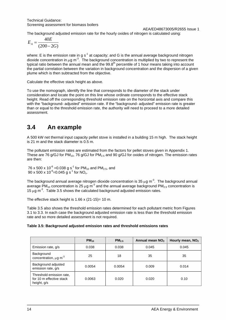
The background adjusted emission rate for the hourly oxides of nitrogen is calculated using:
)2200(40
GEEA −
=
where: E is the emission rate in g s-1 at capacity; and G is the annual average background nitrogen dioxide concentration in µg m-3. The background concentration is multiplied by two to represent the typical ratio between the annual mean and the 99.8th percentile of 1 hour means taking into account the partial correlation between the variation in background concentration and the dispersion of a given plume which is then subtracted from the objective. Calculate the effective stack height as above. To use the nomograph, identify the line that corresponds to the diameter of the stack under consideration and locate the point on this line whose ordinate corresponds to the effective stack height. Read off the corresponding threshold emission rate on the horizontal axis and compare this with the “background- adjusted” emission rate. If the “background- adjusted” emission rate is greater than or equal to the threshold emission rate, the authority will need to proceed to a more detailed assessment.
3.4 An example A 500 kW net thermal input capacity pellet stove is installed in a building 15 m high. The stack height is 21 m and the stack diameter is 0.5 m. The pollutant emission rates are estimated from the factors for pellet stoves given in Appendix 1. These are 76 g/GJ for PM10, 76 g/GJ for PM2.5 and 90 g/GJ for oxides of nitrogen. The emission rates are then: 76 x 500 x 10-6 =0.038 g s-1 for PM10 and PM2.5, and 90 x 500 x 10-6=0.045 g s-1 for NOx. The background annual average nitrogen dioxide concentration is 35 µg m-3. The background annual average PM10 concentration is 25 µg m-3 and the annual average background PM2.5 concentration is 15 µg m-3. Table 3.5 shows the calculated background adjusted emission rates. The effective stack height is 1.66 x (21-15)= 10 m. Table 3.5 also shows the threshold emission rates determined for each pollutant metric from Figures 3.1 to 3.3. In each case the background adjusted emission rate is less than the threshold emission rate and so more detailed assessment is not required.
Table 3.5: Background adjusted emission rates and threshold emissions rates
PM10 PM2.5 Annual mean NO2 Hourly mean, NO2
Emission rate, g/s 0.038 0.038 0.045 0.045
Background concentration, µg m-3 25 18 35 35
Background adjusted emission rate, g/s 0.0054 0.0054 0.009 0.014
Threshold emission rate, for 10 m effective stack height, g/s
0.0063 0.020 0.020 0.10

Technical Guidance: Screening assessment for biomass boilers AEA/ED48673005/R2655 Issue 1
AEA Energy & Environment 15

Technical Guidance: Screening assessment for biomass boilers AEA/ED48673005/R2655 Issue 1
16 AEA Energy & Environment
4 Combined impacts
4.1 Introduction A number of local authorities have expressed concern that the effects of many small biomass combustion installations that are individually acceptable could combine and lead to unacceptably high particulate matter concentrations. Technical Guidance LAQM.TG(03) provides a nomograph for assessing whether there is a risk of exceeding air quality objectives for PM10 as the result of emissions from domestic solid fuel consumption. The nomograph can be used to assess the potential impact of domestic wood burning. However, the TG(03) nomograph is likely to be excessively conservative when applied to modern solid fuel appliances. The TG(03) nomograph is applicable to domestic heating. However, there is potentially widespread application of biomass combustion for service sector heating (commercial offices, communication and transport, education, government, health, hotel and catering, retail, sport and leisure, warehouses) and for heating small industrial units. This section of the report proposes a revised nomograph that takes into account the improved emissions performance of modern solid fuel appliances. The revised nomograph can be applied to both domestic and service sector heating.
4.2 Dispersion modelling The dispersion model ADMS4 was used to predict the maximum annual average ground level concentration resulting from a uniform emission rate applied over areas of 1 km2, 4 km2 and 16 km2 representing villages, small towns and relatively large towns respectively. Each area was represented as a square volume source, 10 m deep. The model used hourly sequential meteorological data for Heathrow Airport for 2006. The surface roughness of the modelled area was assumed to be 1 m. Urban heat island effects were taken into account by setting a lower limit of 10 m and 20 m for the Monin-Obukhov length for the small and large towns respectively: no restriction was applied for the “village”. The maximum predicted annual mean concentrations for a uniform emission rate of 1 g s-1 km-2 were 12.4 µg m-3 for the “village”, 16.9 µg m-3 for the “small town” and 17.3 µg m-3 for the “large town”. On this basis it was calculated that annual emissions of 2.543 tonne km-2, 1.866 tonne km-2 and 1.823 tonne km-2 would result in an increase in the annual mean concentrations of 1 µg m-3 in the “village”, “small town” and “large town” respectively.
4.3 Estimating emissions Total domestic energy consumption for space and water heating during 2005 was 39.1 million tonnes of oil equivalent. There were 25,650,000 households in the UK in 2005. (BERR energy consumption tables). Thus the average fuel consumption per household for space and water heating was 1.524 tonnes of oil equivalent (63.8 GJ gross). Total energy consumption by the service sector for space and water heating in 2005 was 10.866 million tonnes of oil equivalent. Service sector floor area was 854 km2. (BERR energy consumption tables). Thus the average fuel consumption per hectare of floor space for space and water heating by the service sector was 127 tonnes of oil equivalent (5327 GJ gross). Emission factors taken from the EMEP/CORINAIR Emission Inventory Guidebook – 2006 for solid fuel appliances are summarised in Appendix 1. In addition, Appendix 1 includes an assessment of achievable emissions from the best available technology for domestic appliances based on measurement data reported to AEA Technology for exemption of appliances under the Clean Air Act. The emission factors are presented in terms of net energy input, whereas the fuel consumption estimates are expressed in terms of gross energy content. The ratio of net to gross calorific values is

Technical Guidance: Screening assessment for biomass boilers AEA/ED48673005/R2655 Issue 1
AEA Energy & Environment 17
typically 0.95 for coal, 0.5 for wood consumed in domestic appliances and 0.84 for wood consumed in industrial appliances (Digest of UK Energy Statistics). Wood pellets used in domestic appliances have been assumed to have a calorific value ratio of 0.84. Table 4.1 shows the estimated annual emissions per household from domestic appliances and the estimated annual per emissions per hectare of floorspace for service sector applications.

Technical Guidance: Screening assessment for biomass boilers AEA/ED48673005/R2655 Issue 1
18 AEA Energy & Environment
Table 4.1: Estimated annual emissions per household or hectare of service sector floorspace
Appliance type Fuel Emissions per household, kg year-1
Emissions per hectare of service sector floorspace, kg year-1
PM10 PM2.5 PM10 PM2.5
Coal 20.00 20.00 1670 1670 Fireplace
Wood 27.43 27.12 2291 2264
Coal 27.27 27.27 2277 2277
Solid smokeless fuel 6.06 6.06 506 506 Stove
Wood 25.84 25.84 2157 2157
Coal 14.55 13.33 1215 1113 Advanced stove
Wood 7.66 7.66 639 639
Pellet stove Wood 4.07 4.07 340 340
Coal 23.03 21.82 1923 1822
Solid smokeless fuels 6.06 6.06 506 506 Boiler<50 kWth
Wood 15.15 15.15 1265 1265
Coal 962 860
Solid smokeless fuels 405 405 Boiler > 50 kW th and < 1MW th
Wood 1074 1074
Coal 385 364 Boiler>1MW th
Wood 300 291
Coal 8.49 7.88 708 658 Advanced manual boiler
Wood 2.42 2.42 202 202
Coal 4.61 4.36 385 364 Advanced automatic boiler
Wood 3.54 3.54 295 295
Coal 30 25 Boiler, with fabric filter<20 mg/Nm3 TSP Wood 31 27
Coal 127 61 Older boiler with fabric filter or electrostatic precipitator <100 mg/Nm3 TSP Wood 112 54
Coal 304 177 Boiler with uncontrolled multicyclone Wood 313 246
Best available domestic Wood 1.07 1.07

Technical Guidance: Screening assessment for biomass boilers AEA/ED48673005/R2655 Issue 1
AEA Energy & Environment 19
4.4 Method Solid fuel burning tends to be concentrated into small areas or estates, which generally cover less than 1 km2. The procedure adopted for LAQM.TG(03) required authorities to identify the area with the highest density of solid fuel burning houses and then to estimate the number of houses burning coal, smokeless fuel or wood within a 500 m x 500 m grid square. The proportion of space in the 500 m x 500m square not occupied by solid fuel burning houses was also required, together with the annual mean background concentration. A similar procedure is recommended here:
1 Identify the areas with the highest densities of houses and service sector appliances burning solid fuels.
2 Identify the types of solid fuel appliance used in each area from the list in Table 4.1. Appendix 1 provides further descriptions of the appliance types.
3 Count the numbers of each domestic heating appliance type in the identified 500 x 500 m squares. Estimate the floorspace occupied in the service sector in each of the identified 500 m x 500 m squares for each of the identified types of solid fuel burning plant.
4 Multiply the number of houses for each appliance type by the annual household emission shown in Table 4.1. Sum the emissions from each of the domestic appliance types to give the total annual domestic emission from the 500 m x 500 m square.
5 Multiply the service sector floorspace (in hectares) for each appliance type by the annual service sector emission per hectare. Sum the emissions from each of the service sector appliance types to give the total annual service sector emission from the 500 m x 500m square. Add the service sector emissions to the domestic emissions to give the total emissions from the square.
6 Estimate the fraction of space in the 500 m x 500 m square occupied by solid fuel burning premises or domestic properties. Divide the annual emission by the fraction occupied by solid fuel burning to give the emissions density for the square (kg emissions per 500 m x 500 m area).
7 Figure 4.1 describes the annual emissions from a 500 m x 500m square (the threshold emissions density) that may give rise to an exceedence of the 24 hour mean objective for PM10 for a particular estimated background PM10 concentration. If the emissions density from the square exceeds the threshold emissions density shown in Fig. 4.1, then the authority will need to proceed to a detailed assessment.
8 Figure 4.2 describes the annual emissions from a 500 m x 500m square (the threshold emissions density) that may give rise to an exceedence of the annual mean cap for PM2.5 for a particular estimated background PM2.5 concentration. If the emissions density from the square exceeds the threshold emissions density shown in Fig. 4.2, then the authority will need to proceed to a detailed assessment. Where the assessment is being made against a different annual mean objective, the nomograph may still be used by adjusting the background concentration. (For example, for authorities in Scotland where the annual mean cap for PM2.5 is 12 µg m-3, the background concentration should be increased by 13 µg m-3).
9 Figure 4.3 describes the annual emissions from a 500 m x 500m square (the threshold emissions density) that may give rise to an exceedence of the annual mean objective for PM10 for Scotland of 20 µg m-3 for a particular estimated background PM10 concentration. If the emissions density from the square exceeds the threshold emissions density shown in Fig. 4.1, then the authority will need to proceed to a detailed assessment.

Technical Guidance: Screening assessment for biomass boilers AEA/ED48673005/R2655 Issue 1
20 AEA Energy & Environment
Fig. 4.1: Threshold emissions density of emissions from a 500 m x 500 m area that may produce an exceedence of the daily average objective for PM10
Fig. 4.2: Threshold emissions density of emissions from a 500 m x 500 m area that may produce an exceedence of the annual average cap for PM2.5
0
1000
2000
3000
4000
5000
6000
7000
8000
9000
10000
11000
15 16 17 18 19 20 21 22 23 24 25 26 27 28 29 30 31 32 33
Background PM10 concentration, ug/m3
Thre
shol
d em
issi
on ra
te, k
g/an
num
VillageSmall townLarge town
0
1000
2000
3000
4000
5000
6000
7000
15 16 17 18 19 20 21 22 23 24 25 26
Background PM2.5 concentration, ug/m3
Thre
shol
d em
issi
on ra
te, k
g/an
num
VillageSmall townLarge town

Technical Guidance: Screening assessment for biomass boilers AEA/ED48673005/R2655 Issue 1
AEA Energy & Environment 21
Fig. 4.3: Threshold emissions density of emissions from a 500 m x 500 m area that may produce an exceedence of the annual average objective for PM10 in Scotland
4.5 Example Consider a 500 m x 500 m square containing a new 6 hectare development of 400 houses on the outskirts of a large town. The houses are fitted with advanced automatic wood pellet boilers. The new development adjoins an 8 hectare older estate. The older estate has largely converted to gas heating but there remain 50 houses that use conventional boilers burning coal. The 500 m x 500 m square also contains a school with floor area of 0.2 hectares in a plot of 1 hectare: the school is heated by means of a wood-burning advanced automatic boiler. There is also a public house with floor area of 0.1 hectare in a plot of 0.5 hectare; the public house is heated by open wood fires. The remaining part of the 500 m x 500 m square does not contain premises burning solid fuels. The total emissions of PM10 from the residential area is: 400 x 3.54+50 x 23.03=1416+1152=2568 kg. The total emissions of PM10 from the school and the public house are: 0.2 x 295 + 0.1 x 2291 =59 +229 =288 kg. The total emissions from all solid fuel sources are then 2568 + 288 =2856 kg. The area of the 500 x 500 m square occupied by solid fuel heated premises is: 6+8+1+0.5=15.5 hectares. Thus the fraction occupied is 9.5/25 =0.62. The emissions density is then 2856/0.62=4606 kg /year. The background PM10 in the area is estimated from the national maps to be 21 µg m-3. From Fig. 4.1, the threshold emission density is 5013 kg/ year. In this case, the calculated emissions for the 500 m x
0
1000
2000
3000
4000
5000
10 11 12 13 14 15 16 17 18 19
Background PM10 concentration, ug/m3
Thre
shol
d em
issi
on ra
te, k
g/an
num
VillageSmall townLarge town

Technical Guidance: Screening assessment for biomass boilers AEA/ED48673005/R2655 Issue 1
22 AEA Energy & Environment
500 m square are less than the threshold and there is no requirement to carry out a detailed assessment.

AEA Energy & Environment
Appendix 1
Emission factors for solid fuel combustion


AEA Energy & Environment
Emission factor, g/GJ
net Description Corinair category Fuel
PM10 PM2.5 NOx Coal 330 330 60 Open fireplaces: this type of fireplaces is of very simple design - basic combustion chamber, which is
directly connected to the chimney. Fireplaces have large openings to the fire bed. Some of them have dampers above the combustion area to limit the room air intake and resulting heat looses when fireplace is not being used. The heat energy is transferred to dwelling mainly by radiation. Open fireplaces are usually of masonry type and have very low efficiency while having significant emissions of TSP, CO, NMVOC and PAH resulting from the incomplete combustion of the fuels. Partly closed fireplaces are equipped with louvers and glass doors to reduce the intake of combustion air. Some masonry fireplaces are designed or retrofitted in that way in order to improve their overall efficiency.
Fireplace Wood 860 850 50
Coal 450 450 100
Solid smokeless fuel 100 100 100
Closed fireplaces are equipped with front doors and may have distribution of combustion air to primary and secondary as well as a system to discharge the exhaust gases. They are prefabricated and installed as stand-alone units or as a fireplace inserts installed in existing masonry fireplaces. Because of the design and the combustion principle, closed fireplaces resemble stoves and their efficiency usually exceeds 50 %. They have similar emissions like stoves, i.e., lower than open, as well as, partly closed fireplaces. For this reason they can be rated among stoves. Conventional stoves have poorly organised combustion process resulting in low efficiency (40% to 50%) and significant emissions of pollutants mainly originating from incomplete combustion (TSP, CO, NMVOC and PAH). Their autonomy is low, lasting from 3 to 8 hours. Those, which are equipped with hot plate zones, are used also for cooking - kitchen stoves. Some of them could also be used for hot water preparation. Classic energy efficient stoves; due to the utilization of secondary air in the combustion chamber their efficiency is between 55% to 75% and emission of pollutants are lower, their autonomy ranges from 6 to 12 hours.
Stove
Wood 810 810 50
Coal 240 220 150 Advanced combustion stoves: These stoves are characterized by multiple air inlets and pre-heating of secondary combustion air by heat exchange with hot flue gases. This design results in increased efficiency (near 70% at full load) and reduced CO, NMVOC and TSP emissions in comparison with the conventional stoves.
Advanced stove Wood 240 240 90
Pellet stoves: They can be fed only with pelletised fuels such as wood pellets, which are distributed to the combustion chamber by a fuel feeder from a small fuel storage. Pellets stoves are equipped with a fan and electronic control system for supply of the combustion air. For this reason they are characterized by high efficiency (above 80% up to 90%) and low emissions of CO, NMVOC, TSP and PAH.
Pellet stove Wood 76 76 90
Coal 380 360 130 Solid smokeless
fuels 100 100 200 Conventional natural draught boilers < 50 kWth Boiler<50 kWth
Wood 475 475 120

Emission factor, g/GJ net Description Corinair
category Fuel PM10 PM2.5 NOx
Coal 190 170 160 Solid smokeless
fuels 80 80 150 Conventional natural draught boilers > 50 kWth and <1 MW th Boiler > 50 kW th and < 1MW th
Wood 240 240 150
Coal 76 72 180 Conventional natural draught boilers >1 MW th Boiler>1MW th
Wood 67 65 150
Coal 140 130 200 Advance, under-fire coal boilers: In general the design and the combustion technique are similar to the conventional under-fire boiler. The main difference is that a fan controls the flue gases flow. Control system for the primary and secondary air might lead to increase in efficiency above 80% (usually between 70% and 80%). Downdraught wood boilers: This type of boiler is considered state of the art in the lump wood combustion. It has two chambers, first one where the fuel is fed for partial devolatilisation and combustion of the fuel layer, and a secondary chamber, where burning of the released combustible gases occurs. The advantage of this boiler is that the flue gases are forced to flow down through holes in a ceramic grate and thus are burned at high temperature within the secondary combustion chamber and ceramic tunnel. Owing to the optimized combustion process, emissions due to incomplete combustion are low.
Advanced manual boiler Wood 76 76 150
Coal 76 72 200 Stoker coal burners: The fuel with low ash contents and the grain size of between 4 mm up to 25 mm is automatically fed into to a retort by a screw conveyor. Stoker boiler is characterized by higher efficiency, usually above 80%. The advantage of stoker boiler is that it can operate with high efficiency within load range from 30% to nominal capacity. In a properly operated stoker, emissions of pollutants resulting from incomplete combustion are significantly lower, however NOx increases due to the higher combustion temperature. Wood pellet boiler has a fully automatic system for feeding of pellet fuels and for supply of combustion air, which is distributed into primary and secondary. The boilers are equipped with a smaller pellet storage, which is fuelled manually or by an automatic system from larger chamber storage. The pellets are introduced by screw into burner. These boilers are characterised by a high efficiency (usually above 80%) and their emissions are comparable to those of liquid fuel boilers.
Advanced automatic boiler Wood 66 66 150
Best Available Technology Domestic Boilers Wood 20* 20
ABATED Emissions
Coal 6 5 180 Boiler, with fabric filter<20 mg/Nm3 TSP
Wood 7 6 150
*Based on an assessment of achievable performance from measurement data reported to AEA Technology for approval as exempt appliances under the Clean Air Act

AEA Energy & Environment
Emission factor, g/GJ net Description Corinair
category Fuel PM10 PM2.5 NOx
Coal 25 12 180 Older boiler with fabric filter or electrostatic precipitator <100 mg/Nm3 TSP
Wood 25 12 150
Coal 60 35 180 Boiler with uncontrolled multicyclone
Wood 70 55 150