Embed Size (px)
Citation preview

Technical Guidance Document for Water Quality Management Plans
Prepared by: CDM Smith Inc.
Prepared for and Submitted by:
The County of San Bernardino Areawide Stormwater Program NPDES No. CAS618036, ORDER No. R8-2010-0036
Submitted To:
California Water Quality Control Board – Santa Ana Region
June 7, 2013
Approval Date: June 21, 2013 Effective Date: September 19, 2013

TABLE OF CONTENTS
i
Technical Guidance Document
Section 1 - Introduction ......................................................................................................... 1
1.1 Purpose of Guidance ............................................................................................................. 1
1.2 Regulatory Background ...................................................................................................... 1
1.3 Stormwater Management ................................................................................................. 3
1.3.1 Low Impact Development............................................................................................. 3
1.3.2 Goals of LID ................................................................................................................... 4
1.3.3 Benefits of LID ............................................................................................................... 4
1.4 WQMP Guidance Revision ................................................................................................. 5
1.5 Guidance Applicability ....................................................................................................... 6
1.5.1 Priority Projects ........................................................................................................... 6
1.5.2 Transportation Projects ............................................................................................... 6
1.6 How to Use this Guidance ................................................................................................. 8
Section 2 – WQMP Development Process .............................................................................. 9
2.1 Introduction ....................................................................................................................... 9
2.2 Process Overview ............................................................................................................... 9
2.3 Working with Your Local Jurisdiction ............................................................................... 11
2.3.1 Getting Started ........................................................................................................... 11
2.3.2 Resource Information ................................................................................................. 11
2.4 Preliminary WQMP Submittal ......................................................................................... 13
2.5 Final WQMP Submittal .................................................................................................... 13
Section 3 – Project Evaluation .............................................................................................. 14
3.1 Introduction ..................................................................................................................... 14
3.2 Site Assessment ............................................................................................................... 15
3.2.1 Project Location .......................................................................................................... 15
3.2.2 Site Topography and Hydrography ............................................................................. 16
3.2.3 Soils and Geologic Conditions .................................................................................... 17
3.2.4 Groundwater Considerations ..................................................................................... 18
3.2.5 Environmental Concerns ............................................................................................ 18
3.2.6 Existing Development and Utilities ............................................................................ 18
3.3 Pollutants of Concern ...................................................................................................... 19
3.3.1 Land Use and Potential Pollutants of Concern ........................................................... 20
3.3.2 Expected Pollutants of Concern ................................................................................. 22
3.3.3 Receiving Water Impairments and TMDLs ................................................................. 22
3.4 Hydrologic Conditions of Concern ................................................................................... 22
3.4.1 Susceptibility of Receiving Waters to Hydromodification Impacts ............................ 24

ii
3.4.2 Expected Hydrologic Conditions of Concern .............................................................. 24
3.5 Regional Stormwater Management ................................................................................ 25
Section 4 – Project-Specific Performance Criteria ................................................................. 27
4.1 LID Performance Criteria ................................................................................................. 28
4.2 HCOC Performance Criteria ............................................................................................. 29
4.2.1 Runoff Volume ............................................................................................................ 30
4.2.2 Time of Concentration ................................................................................................ 31
4.2.3 Peak Runoff ................................................................................................................. 33
4.3 Case Studies ..................................................................................................................... 34
4.3.1 Case Studies - LID Performance Criteria ..................................................................... 36
4.3.2 Case Studies - HCOC Performance Criteria ................................................................ 37
Section 5 – Low Impact Development BMP Evaluation and Selection ................................... 42
5.1 Introduction ..................................................................................................................... 42
5.2 Selection of LID Preventive Measures ............................................................................. 43
5.2.1 Site Planning and Design Practices ............................................................................. 44
5.2.2 Construction Practices ................................................................................................ 47
5.2.3 Post-Construction ....................................................................................................... 48
5.3 Selection of LID Mitigative Measures and BMPs ............................................................. 48
5.3.1 Hierarchy of BMP Types ............................................................................................. 48
5.3.2 General Feasibility Criteria for Use of Required LID BMPs ......................................... 50
5.4 Evaluation of LID BMPs .................................................................................................... 55
5.4.1 Hydrologic Source Control .......................................................................................... 55
5.4.2 Infiltration BMPs ......................................................................................................... 60
5.4.3 Harvest and Use BMPs................................................................................................ 64
5.4.4 Biotreatment BMPs .................................................................................................... 65
5.5 WQMP Conformance Analysis ......................................................................................... 73
5.5.1 Criteria for MEP Determination .................................................................................... 74
5.5.2 Hydrologic Source Controls ........................................................................................ 77
5.5.3 LID Infiltration BMPs ................................................................................................... 77
5.5.4 Harvest and Use BMPs................................................................................................ 78
5.5.5 Biotreatment BMPs .................................................................................................... 78
5.5.6 Case Study Conformance Analysis .............................................................................. 79
5.6 Hydromodification Control .............................................................................................. 81
5.6.1 Incorporating Hydromodification into Project WQMPs ............................................. 81
5.6.2 Hydromodification Control BMPs ............................................................................... 82
Section 6 – Alternative Compliance Plan .............................................................................. 84
6.1 Introduction ..................................................................................................................... 84
6.2 Water Quality Credits ...................................................................................................... 86

iii
6.2.1 Qualifying Projects ........................................................................................................ 86
6.2.2 Applying Water Quality Credits ..................................................................................... 87
6.3 Treatment Control BMPs ..................................................................................................... 88
6.4 Waivers ................................................................................................................................ 90
6.5 In-Lieu Fund ......................................................................................................................... 90
Section 7 – Source Control BMPs ......................................................................................... 92
7.1 Introduction ..................................................................................................................... 92
7.2 Non-Structural Source Control BMPs .............................................................................. 92
7.3 Structural Source Control BMPs .......................................................................................... 96
7.4 Selecting Source Control BMPs ..................................................................................... 104
Section 8 – Post-Construction BMP Requirements.............................................................. 106
8.1 BMP Maintenance Mechanisms .................................................................................... 106
8.2 BMP Maintenance Requirements ................................................................................. 107
8.2.1 Operation and Maintenance Plan ............................................................................... 107
8.2.2 O&M Commitments .................................................................................................... 107
8.2.3 Maintenance Agreements ........................................................................................ 108
8.3 Permit Closeout Requirements ..................................................................................... 109
Section 9 -References ........................................................................................................ 110
Appendix A - Transportation Project BMP Guidance............................................................... A
Appendix B – WQMP Template .............................................................................................. B
Appendix C – San Bernardino County Hydrology Manual (Selected Figures)............................ C
Appendix C-1 – SB County Hydrology Manual Figure D-1, Time of Concentration Nomograph ........... C-1
Appendix C - 2 – SB County Hydrology Manual Figure C-3, Curve Numbers of Hydrologic Soil ............ C-2
Appendix C - 3 – SB County Hydrology Manual Figure C‐6, Infiltration Rate for Pervious Areas versus
SCS Curve Numbers ........................................................................................................................ C-3
Appendix C - 4 – SB County Hydrology Manual Figure D‐3, Intensity – Duration Curves Calculation
Sheet ............................................................................................................................................... C-4
Appendix D – Section VII – Infiltration Rate Evaluation Protocol and Factor of Safety
Recommendations, Orange County TGD Appendices, May 19, 2011 ................................ D
Appendix E – Section XII – Conceptual Biotreatment Selection, Design, and Maintenance
Criteria Orange County TGD Appendices, May 19, 2011 ................................................... E
Appendix F – HCOC Exemption Criteria and Map .................................................................... F

1
Section 1 - Introduction
1.1 Purpose of Guidance
The 2010 Municipal Separate Storm Sewer System Permit (MS4 Permit), adopted by the Santa
Ana Regional Water Quality Control Board (RWQCB), and issued to San Bernardino County,
requires all new development and significant redevelopment projects covered by this Order to
incorporate Low Impact Development (LID) Best Management Practices to the maximum extent
practicable (MEP). In addition, the Order also requires development of a standard design and
post-development best management practice (BMP) guidance for incorporation, where feasible
and applicable, of site design/LID, source control, and treatment control BMP (where feasible
and applicable) and Hydrologic Conditions of Concern (HCOC) mitigation measures to the MEP
on public street, road, highway, and freeway improvement projects (“transportation projects”)
to reduce the discharge of pollutants to receiving waters. The purpose of this Technical
Guidance Document (TGD) for Water Quality Management Plan(s) (WQMP) is to provide
direction to project proponents on the regulatory requirements applicable to a private or public
development activity, including public works transportation projects, from project conception
to completion. This TGD is intended to serve as a living document, which will be updated as
needed to remain applicable beyond the current Permit term. Any non-substantive updates to
the TGD and Transportation Project BMP Guidance and applicable Template will be provided in
the annual report. Future substantive updates shall be submitted to the RWQCB for review and
approval, prior to implementation.
1.2 Regulatory Background
The 1972 Federal Water Pollution Control Act and its amendments comprise what is commonly
known as the Clean Water Act (CWA). The CWA provides the basis for the protection of all
inland surface waters, estuaries, and coastal waters. The federal Environmental Protection
Agency (EPA) is responsible for ensuring the implementation of the CWA and its governing
regulations (primarily Title 40 of the Code of Federal Regulations) at the state level.
California‘s Porter-Cologne Water Quality Control Act of 1970 and its implementing regulations
established the RWQCB as the agency responsible for implementing CWA and Porter-Cologne
requirements in the Santa Ana River Watershed. These requirements include adoption of a
Water Quality Control Plan (“Basin Plan”) to protect inland freshwaters and estuaries. The Basin
Plan identifies the beneficial uses for waterbodies in the Santa Ana River watershed, establishes
the water quality objectives required to protect those uses, and provides an implementation
plan to protect water quality in the region (RWQCB 1995 and subsequent amendments).

2
As part of its responsibility to protect beneficial uses of waters in the Santa Ana River
Watershed in San Bernardino County, the RWQCB issued permits to regulate discharges from
Municipal Separate Storm Sewer System (MS4) facilities within the County.
The jurisdictions covered by this permit include:
San Bernardino County Flood Control District
County of San Bernardino
City of Big Bear Lake
City of Chino
City of Chino Hills
City of Colton
City of Fontana
City of Grand Terrace
City of Highland
City of Loma Linda
City of Montclair
City of Ontario
City of Rancho Cucamonga
City of Redlands
City of Rialto
City of San Bernardino
City of Upland
City of Yucaipa
The first MS4 Permit for these Permittees was issued by the RWQCB in 1990. This permit
focused primarily on program development, which included establishment of the Drainage Area
Management Plan (now the Municipal Stormwater Management Plan) and implementation of
public education and staff training on stormwater quality concerns.
Revised permits were issued in 1996 and 2002. Under these permits the stormwater
management requirements applicable to new development and significant redevelopment
projects evolved. Accordingly, during these permits the Model WQMP Guidance was revised
twice (2000 and 2005) to incorporate increasingly stringent requirements applicable to
development activities.
The RWQCB issued the current MS4 Permit on January 29, 2010 (Order No. 2010-0036, NPDES
No. CAS618036). This permit contains many new requirements that further increase the
complexity and costs associated with the management of stormwater in the permitted area,
3
especially for new development and significant redevelopment projects and public works
transportation projects. To address these new regulatory mandates, the MS4 Permit program
has again revised the Model WQMP Guidance. This updated TGD replaces all previous guidance
applicable to development projects within the Santa Ana River Watershed.
1.3 Stormwater Management
Development activities typically change pre-development hydrologic conditions by altering
drainage patterns and increasing impervious area. Impervious areas include streets, walkways,
driveways, rooftops, and parking lots which traditionally not only do not infiltrate stormwater
runoff, but instead increase the rate and volume of runoff of precipitation during storm events.
The traditional approach to storm drain design associated with a development activity focused
on capturing and transporting stormwater runoff off-site in the most efficient manner to
protect people and property from potential flood damage. Urban constructed drainage
systems, comprised of street gutters, catch basins, belowground storm drain piping, detention
basins, and open or closed channels (i.e., the MS4) have functioned to convey runoff from
completed developments to the nearest receiving water.
Stormwater runoff mobilizes pollutants on land surfaces and carries them downstream via the
MS4 to storm drain systems where impacts to receiving water quality may occur. In addition,
increased runoff volume from development activities can cause erosion in downstream waters
further impacting water quality. Accordingly, over a number of years stormwater management
has evolved from simply managing the quantity of runoff from a development site to managing
both the quantity and quality of the runoff to reduce impacts to downstream receiving waters.
The recently adopted MS4 Permit for San Bernardino County includes significant changes to the
requirements for managing the quantity and quality of runoff from urban developments. These
requirements include the incorporation of LID practices to maintain the pre-development
hydrology of a development site to the maximum extent practicable.
1.3.1 Low Impact Development
LID principles are increasingly being applied in urban environments as a strategy to reduce
receiving water impacts from stormwater runoff. A typical LID definition is:
“…a stormwater management strategy that emphasizes conservation and the use of existing
natural site features integrated with distributed, small-scale stormwater controls to more
closely mimic natural hydrologic patterns in residential, commercial and industrial
setting.”*Washington State University Puget Sound Action Team as reported in Green
Infrastructure for Los Angeles: Addressing Urban Runoff and Water Supply through LID,
2009]

4
Accordingly, the San Bernardino County Stormwater Program defines LID as “a stormwater
management and land development strategy that combines a hydrologically functional site
design with pollution prevention measures to compensate for land development impacts on
hydrology and water quality. LID techniques mimic the site pre-development site hydrology by
using site design techniques that store, infiltrate, evapotranspire, bio-filter or detain runoff close
to its source”.
1.3.2 Goals of LID
The primary goal of LID is to preserve the pre-development hydrology of a project site. Changes
in runoff characteristics that result in increased post-development runoff can be reduced
through the use of structural and nonstructural BMPs that store, infiltrate, evaporate, and
detain runoff. The desired outcome of the use of these BMPs is to mimic the local watershed’s
natural hydrologic functions to the maximum extent practicable. There are many site design
techniques that may be deployed on a project site to allow the site to function in a manner
similar to how it functioned prior to development. With the incorporation of LID practices,
downstream waters that ultimately receive stormwater runoff from developed sites will
experience fewer negative impacts and have in-stream flows that more closely approximate
pre-development runoff conditions.
1.3.3 Benefits of LID
The benefits of implementing LID practices can be significant. Examples include:
Maintain pre-development hydrology – Maintaining the pre-development hydrology
reduces the volume of water that must be conveyed offsite, which not only reduces
erosion and sedimentation impacts, but ultimately reduces downstream flood control
requirements.
Water quality benefits – Pollutant loads carried by stormwater runoff can be greatly
reduced through retention of stormwater and pollutants onsite and use of BMPs that
biofilter pollutants onsite, thus reducing pollutants that would normally be discharged
directly to the storm drain system.
Groundwater recharge – LID emphasizes infiltration of runoff onsite which has the
potential to increase local water supply availability from groundwater sources.
Aesthetic appeal - LID involves the use of site design practices that minimize the footprint
of proposed developments which increases preservation of open space.

5
1.4 WQMP Guidance Revision
The 2010 MS4 Permit significantly changed the requirements applicable to development
activities by substantially changing how LID practices are incorporated into developments.
Specifically, as stated in the Permit:
“This Order requires project proponents to first consider preventative and conservation
techniques (e.g., preserve and protect natural features to the maximum extent practicable)
prior to considering mitigative techniques (structural treatment, such as infiltration systems).
The mitigative measures should be prioritized with the highest priority for BMPs that remove
storm water pollutants and reduce runoff volume, such as infiltration, then other BMPs, such
as harvesting and use, evapotranspiration and biotreatment should be considered. To the
maximum extent practicable, these LID BMPs must be implemented at the project site. The
Regional Board recognizes that site conditions, including site soils, contaminant plumes, high
groundwater levels, etc., could limit the applicability of infiltration and other LID BMPs at
certain project sites. Where LID BMPs are not feasible at the project site, more traditional, but
equally effective control measures should be implemented. This Order provides for
alternatives and in-lieu programs where the preferred LID BMPs are infeasible (RWQCB Order
No. 2010-0036, NPDES No. CAS618036, Section II.G.6).”
To address these requirements, this document replaces the existing 2005 Model WQMP
Guidance for the Santa Ana River Watershed (revised in May 2012) in its entirety. Key changes
to the WQMP Guidance include:
Revised HCOC performance criteria based on MS4 Permit requirements to conduct
hydrologic analysis for only the 2-year storm event (2005 Guidance also required analysis
of 1-year and 5-year storm events)
More detailed description of LID site design considerations including preventative
principles (e.g. minimizing impervious area) and mitigative lot level hydrologic source
controls (e.g. residential rooftop downspout disconnection)
New approach to BMP selection and evaluation, whereby LID BMPs are evaluated
according to the hierarchy specified in the 2010 MS4 Permit
Updated tables of pollutant removal effectiveness for BMPs that treat and release runoff
to the MS4
New required calculations to demonstrate that planned LID BMPs are capable of capturing
runoff from the water quality design storm event (Design Capture Volume or “DCV”)

6
New approach to determine if implementation of a BMP type is not feasible, including
initial site screening factors (e.g. high groundwater conditions) and detailed assessment of
project specific feasibility (e.g. infiltration basin in poorly draining soils)
Inclusion of a Transportation Guidance specific to certain types of public works
transportation projects. Application of this Guidance to transportation projects results in
documentation that is functionally equivalent to the WQMP prepared for new
development or significant re-development projects.
1.5 Guidance Applicability
All proponents of development projects are required to use this TGD and associated Template
to obtain the necessary approvals for implementation of proposed new development and
significant re-development activities and proposed transportation projects. Project submittal
requirements vary depending on the type of project as well as whether the project proponent is
a private entity or public agency. The following sections provide additional information
regarding the applicability of this TGD.
1.5.1 Priority Projects
Table 1-1 defines development activities classified as Priority Projects. This TGD establishes
requirements for project proponents (both private and public agency project proponents) to
meet the minimum County-wide stormwater management requirements applicable to Priority
Projects. In general terms, the project proponent shall incorporate infiltration LID BMP to the
MEP; and use biotreatment and harvest and use BMP for the remainder of the DCV.
The project proponent should consult the Local Implementation Plan (LIP) established for the
jurisdiction within which the project is proposed, as requirements may be applicable for non-
priority /non-category projects. The LIP provides information regarding how the WQMP
development process is implemented within the local jurisdiction and identifies any additional
WQMP development requirements, i.e., in addition to the requirements identified in this
document.
No building or grading permits will be issued to Priority Projects by any local jurisdiction
without an approved final project-specific WQMP.
1.5.2 Transportation Projects
Transportation projects that are part of a new development or significant re-development
project implemented by a private developer are subject to the requirements applicable to
Priority Projects (e.g., see Section 1.5 and Table 1-1 Priority Project Category No. 2), regardless
of whether the roads remain private or are dedicated to public right-of-way after the
development is complete.

7
Public works transportation projects not part of a Priority Project may be subject to the
requirements of the Transportation Project BMP Guidance, which describes the stormwater
management requirements applicable to selected categories of transportation projects. The
Transportation Project BMP Guidance is incorporated into this document as Appendix A. Similar
to a Priority Project; it is recommended that a project proponent also consult the LIP for the
Table 1-1. Priority Projects(1)
Category No.
Project Type
1
All significant re-development1 projects - defined as the addition or replacement of 5,000 or
more square feet (sq. ft) of impervious surface on an already developed site subject to discretionary approval of the permitting jurisdiction. In addition: Re-development does not include: Routine maintenance activities that are conducted to
maintain original line and grade, hydraulic capacity, original purpose of the facility, or emergency redevelopment activity required to protect public health and safety.
Where re-development results in an increase of less than 50% of the impervious surfaces of a previously existing developed site, and the existing development was not subject to WQMP requirements, the numeric sizing criteria discussed in Section 4 applies only to the addition or replacement, and not to the entire developed site.
Where re-development results in an increase of 50% or more of the impervious surfaces of a previously existing developed site, the numeric sizing criteria discussed in Section 4 applies to the entire development.
2
New development projects that create 10,000 sq. ft. or more of impervious surface (collectively over the entire project site) including commercial, industrial, residential housing subdivisions (i.e., detached single family home subdivisions, multi-family attached subdivisions or townhomes, condominiums, apartments, etc.), mixed-use, and public projects. This category includes development projects on public and private land, which fall under the planning and building authority of the permitting jurisdiction.
3 New development or significant re-development
1 of automotive repair shops (with SIC
2 Codes
5013, 5014, 5541, 7532-7534, 7536-7539) where the project creates, adds and/or replaces 5,000 square feet or more of impervious surface.
4 New development or significant re-development
1 of restaurants (with SIC
2 Code 5812) where
the land area of development is 5,000 sq. ft. or more.
5 All hillside developments of 5,000 sq. ft. or more which are located on areas with known erosive soil conditions or where the natural slope is 25% or more.
6 Developments of 2,500 sq. ft. of impervious surface or more adjacent to (within 200 feet) or discharging directly into environmentally sensitive areas or waterbodies listed on the CWA Section 303(d) list of impaired waters
(3).
7 Parking lots of 5,000 sq. ft. or more exposed to stormwater. A parking lot is defined as land area or facility for the temporary parking or storage of motor vehicles.
8 New development or significant re-development
1 of Retail Gasoline Outlets that are either
5,000 sq. ft. or more, or have a projected average daily traffic of 100 or more vehicles per day.
Non-Priority / Non-Category Projects may be required by the local jurisdiction to implement applicable site design LID and LIP requirements.
(1) – As defined by RWQCB Order R8-2010-0036
(2) - For SIC codes, see: www.osha.gov/oshstats/sicser.html
(3) – See Section 3 for additional information regarding impaired waters
8
local jurisdiction in which the public works transportation project is planned to determine if any
additional local requirements apply to the proposed project.
1.6 How to Use this Guidance
This TGD provides project planning, site design, BMP selection and evaluation, and project
implementation guidance for Priority Projects and transportation projects. Given varying site
conditions throughout the County, it is not practical for this document to address every
potential site design issue that may arise during project conception and design. Furthermore,
this TGD does not supersede any local regulations that affect local development requirements.
While not an all-encompassing document, the TGD does provide detailed discussion of LID BMP
selection, evaluation, and feasibility analysis so that project proponents will understand what
must be incorporated into Priority Projects and road projects to meet County-wide stormwater
management requirements.
The TGD is applicable to new development and re-development projects and includes a WQMP
Template (Appendix B) that is to be used by all project proponents of Priority Projects. Careful
adherence to the methods, calculations, and requirements incorporated into this Template will
increase the likelihood that a complete application for project approval is submitted.
The Transportation Project BMP Guidance (Appendix A) also includes a Template that is to be
used by all project proponents of public works road projects. For road projects, compliance
with the Transportation Project BMP Guidance establishes the documentation that is
functionally equivalent to the WQMP documentation prepared for Priority Projects. In addition,
usage of the Transportation Project BMP Guidance and Template will increase the likelihood
that the project file for a planned road project is complete.
Finally, this document and its accompanying appendices should be used to identify the
minimum requirements applicable to private or public development activities or public works
transportation projects. The information contained herein should be used to facilitate
discussions between the project proponent and responsible agencies for issuing approvals and
permits for the proposed development activities.
In addition, each jurisdiction under the MS4 Permit has adopted a LIP that provides information
specific to the local area where the development activity is planned. The LIP should be
consulted and used along with this TGD to prepare documentation applicable to the proposed
project.

9
Section 2 – WQMP Development Process
2.1 Introduction Use of this Guidance should begin in the earliest possible stages of project conception when a
development site or transportation project is first evaluated to determine how to best utilize
the site to optimize both its development potential and ability to incorporate LID concepts
given the location and characteristics of the property and the area. Ideally, preparation of the
documentation to support the planned project should be a multi-disciplinary effort involving
planning, architecture, engineering, geotechnical expertise, and landscape architecture. Teams
comprised of diverse disciplines can best evaluate how to apply LID practices from project
conception through design and construction.
The process for developing a WQMP for a Priority Project, or the functionally equivalent
documentation for a transportation project requires the systematic completion of a number of
steps before a project can receive the necessary approvals and permits for construction. The
following sections provide an overview of the key steps applicable to proposed projects.
Subsequent sections of this TGD for WQMP and its appendices describe each step in more
detail.
2.2 Process Overview
Figure 2-1 shows the overall process applicable to Priority Projects and public works
transportation projects, including where additional information may be obtained in this
document. The project proponent should consult the LIP for the jurisdiction in which the
project is located. The LIP provides jurisdiction-specific requirements applicable to WQMP
development and transportation projects. At a minimum, all local jurisdictions within the
County of San Bernardino shall implement the following process for a proposed project:
Select Appropriate Guidance - If this is a public works transportation project, Appendix A
provides Guidance applicable to the proposed project. The remaining sections of this
document (Sections 3 through 9) do not apply.
Establish Priority Project Type: Table 1-1 identifies Priority Projects subject to WQMP
development requirements.
Complete Project Evaluation Requirements: Perform California Environmental Quality Act
(CEQA) review, Watershed Action Plan (WAP) analysis and assess local site conditions and
jurisdictional requirements for project (see Section 3).
Develop Site Design: This step involves planning the project using preventative LID site
design principles to minimize the impact of development (see Section 5).

10
Establish Project-Specific Performance Criteria: Based on information developed during
project evaluation and site design, the project proponent establishes LID and HCOC
performance criteria.
Figure 2-1. WQMP Development Process Flowchart
Applicant Meets with Agency Planners/Staff to:
Determine project Category
Review WQMP Requirements
Review CEQA Requirements
Initiate WAP Analysis
Applicant Documents Project Evaluation Requirements (Section 3)
Appendix A – Transportation Guidance
applies to the Proposed Project: Complete
all Applicable Requirements
Applicant Develops Site Design Using LID Principles (Section 5.2)
Applicant Establishes Project-Specific LID DCV and applicable HCOC Requirements (Section 4)
Evaluate Feasibility of On-Site LID BMPs (Section 5.3.2 and Section 5.5)
Maximize Hydrologic Source Control, Infiltration and Biotreatment BMPs
DCV Requirements Fulfilled?
HCOC Requirements Fulfilled?
Applicant Prepares Preliminary WQMP and Site Plan for Approval. After concurrence, Prepare Final WQMP
Select Applicable Source Control BMPs (Section 7)
Address Post-Construction BMP Maintenance Requirements (Section 8)
Applicant Submits Final WQMP for Agency Approval
Re-Evaluate Fulfillment of DCV Requirements using Additional HCOC-Required BMPs
Implement Additional Retention BMPs to meet HCOC requirements (Section 5.6)
Develop Alternative Compliance Plan for Remaining DCV (Section 6)
Verify Regional or Sub-Regional Opportunity in the approved Watershed Action Plan:
Remaining Capacity for Project DCV
Upstream of Water of the US
Operational at Project Completion
Long Term Maintenance Plan approved
YES
YES
NO
NO
Priority Project
Transportation Project

11
Section 4 provides guidelines for computing the project design capture volume (DCV) for LID
and pre- and post-development hydrologic factors (runoff volume, time of concentration, and
peak runoff velocity) for HCOC performance criteria.
2.3 Working with Your Local Jurisdiction
This TGD for WQMP identifies requirements for completion of a WQMP for Priority Projects or
functionally equivalent document for transportation projects that satisfies County-wide MS4
Permit requirements. However, nothing in this TGD supersedes any local development
requirements.
2.3.1 Getting Started
The first step in the approval process for a proposed project is to determine the applicability of
WQMP requirements. If the proposed project is a public works transportation project, then the
requirements established in Appendix A – Transportation Project BMP Guidance may apply. The
Transportation Guidance provides all necessary information regarding its applicability, use and
required documentation. If the project falls within one of the categories listed in Table 1-1, then
it is classified as a Priority Project, and all requirements described in subsequent sections of this
TGD must then be addressed.
Ultimately, the project proponent should consult the local LIP and, if needed, local stormwater
management personnel to verify project approval requirements. It is the responsibility of the
project proponent to determine stormwater management requirements applicable to the
proposed project. Project proponents must also consult the WAP for the project location, to
ensure that WQMP development is aligned with any watershed based plans.
Once it is determined that a project requires a WQMP, the project proponent should work
through each step described in this TGD. The WQMP Template provided in Appendix B will
guide the process and dictate the types of information and analyses required to complete the
WQMP application.
2.3.2 Resource Information
The primary focus of this document is to provide sufficient baseline information for Priority
Projects to guide project proponents through the development of the WQMP application. A
secondary focus is to provide guidance for application of site design/LID-based BMPs, source
control and treatment control BMPs (where applicable to project) to public works
transportation projects (i.e., Appendix A). Regardless of the focus, this document is not
intended to be an exhaustive source of information about LID BMPs, especially with regards to
LID design practices or criteria. Where appropriate in various sections, links to additional
specific reference materials are provided. However, prior to starting preparation of the WQMP,
it is recommended that the project proponent become familiar with the LID literature,

12
especially as it relates to commonly accepted engineering practices. Recommended source
material for transportation projects is provided in the Transportation Project BMP Guidance
(Appendix A). Key source materials for new development and re-development projects include:
Final Draft Model Water Quality Management Plan (WQMP), Orange County (CA)
Stormwater Program, March 22, 2011.
Final Draft Technical Guidance Document for the Preparation of Conceptual/Preliminary
and/or Project WQMPs, Orange County (CA) Stormwater Program, March 22, 2011.
Final Draft Technical Guidance Document Appendices, Orange County (CA) Stormwater
Program, March 22, 2011.
San Bernardino County Watershed Action Plan, San Bernardino County Stormwater
Program, January 29, 2011.
California State Water Resources Control Board and Low Impact Development Center. Low
Impact Development Manual for Southern California: Technical Guidance and Site Planning
Strategies. 2009.
Center for Watershed Protection. Better Site Design: A Handbook for Changing
Development Rules in Your Community. 1998.
Gregory, J.H.; Dukes, M.D.; Jones, P.H.; and G.L. Miller. Effect of Urban Soil Compaction on
Infiltration Rate, Journal of Soil and Water Conservation, 2006, 1(3):117-124.
Maryland Department of Environmental Resource Programs and Planning Division. Low-
Impact Development Design Strategies -An Integrated Design Approach (June 1999) Prince
George’s County, 1999;
http://www.co.pg.md.us/Government/DER/PPD/pgcounty/lidmain.htm.
American Society of Civil Engineers (ASCE). National Stormwater Best Management
Practices (BMP) Database, Version 1.0.
Urban Water Resources Research Council of ASCE Wright Water Engineers. National
Stormwater Best Management Practices Database, 2001.
Bay Area Stormwater Management Agencies Association (BASMAA). Start at the Source
(Detailed discussion of permeable pavements and alternative driveway designs presented),
1999.
Schueler, Thomas R. and Holland, Heather K. Center for Watershed Protection. The Practice
of Watershed Protection, 2000.
Urban Runoff Quality Management, American Society of Civil Engineers (ASCE) Manual and
Report on Engineering Practice No. 87/Water Environment Federation (WEF) Manual of
Practice No.23, 1998.

13
2.4 Preliminary WQMP Submittal
Local jurisdictions shall require the submittal of a preliminary project-specific WQMP
application for review early in the project development process to ensure compliance with all
jurisdictional requirements applicable to development projects (Permit Section XI.D.3). A
Preliminary WQMP may be used by the local jurisdiction during the land use entitlement
process or as part of a project application for discretionary project approval. The level of detail
and content of the preliminary WQMP submittal depends to a large degree on the nature of the
project and local jurisdictional requirements.
The LIP applicable to the project area provides specific information regarding preliminary
WQMP submittal process. This document should be consulted prior to initiating development
of the WQMP.
2.5 Final WQMP Submittal
A completed Final WQMP shall fully address site design measures, LID BMPs, hydromodification
controls, source control BMPs, and treatment control BMPs (where applicable to the project) to
address pollutants or hydrologic conditions of concern. If the project proponent has
demonstrated the infeasibility of use of the aforementioned BMPs, and is participating in an
alternative compliance plan such as a contribution to an in-lieu fund (if available) or mitigation
program, the WQMP must describe and document the Project’s participation. The Final WQMP,
when prepared for submittal for approval, must be certified by the owner, and must include
elements agreed upon at Preliminary WQMP acceptance and any revisions proposed.
The Final WQMP must be consistent with the Preliminary WQMP. If there are any substantial
differences, the local jurisdiction must make a determination that the differences do not
diminish the effectiveness of the BMPs to mitigate or address the project's potential impacts to
water quality. Furthermore, any changes must not result in any new environmental impacts not
previously disclosed in the local jurisdiction's circulated environmental document(s). If the
changes diminish the project's ability to mitigate or address its water quality impacts, or result
in previously undisclosed environmental impacts, the local jurisdiction should require that the
project be subject to further environmental review.
The completed WQMP is to be submitted to the local jurisdiction for review and approval. Any
changes to WQMP elements agreed upon at the Preliminary WQMP phase shall be noted within
the WQMP submitted for final approval. Local jurisdiction staff will review the submittal for
acceptance and approval. Reviews will be documented by the local jurisdiction. Additional
information and submittals may be necessary for final approval. It is the responsibility of the
project proponent to provide the additional information for consideration by the local
jurisdiction.

14
Section 3 – Project Evaluation
3.1 Introduction
The purpose of this section is to describe the site and project information requirements needed
to determine applicable LID and HCOC performance criteria and select and evaluate runoff
capture in proposed BMPs. This information includes site-specific data as well as regional
watershed or jurisdictional plans or requirements. Project evaluation involves several key steps,
including:
Assess site conditions
Determine pollutants of concern (POC)
Determine HCOC
Identify requirements associated with a regional watershed or local jurisdiction that may
affect project planning
Table 3-1. Key Sources of Information for use in Completing a WQMP Project Evaluation
Source Key Information and Intended Use(s)
Watershed Geodatabase
(http://sbcounty.permitrack.com/WAP/)
Downstream receiving waterbodies, downstream
HCOC, NRCS soil properties, ecologically sensitive
areas
RWQCB TMDL Webpage
(http://www.waterboards.ca.gov/santaana/wate
r_issues/programs/tmdl/index.shtml)
Downstream adopted TMDLs, planned TMDLs, and
303(d) listed impairments for Santa Ana River
Watershed receiving waterbodies
NRCS Web Soil Survey
(http://websoilsurvey.nrcs.usda.gov/app/HomeP
age.htm)
General soil and geologic properties
NPDES Permit No. CAS618036 (Order No. R8-
2010-0036) for San Bernardino County
Permittees within the Santa Ana Watershed
Region
(http://www.waterboards.ca.gov/santaana/boar
d_decisions/adopted_orders/orders/2010/10_03
6_SBC_MS4_Permit_01_29_10.pdf)
Basis for project evaluation guidance, regulatory
background for WQMP requirements
County of San Bernardino Hydrology Manual
(http://www.sbcounty.gov/dpw/floodcontrol/pdf
/HydrologyManual.pdf)
and Addendum
(http://www.sbcounty.gov/dpw/floodcontrol/pdf
/20100412_addendum.pdf)
Storm event characterization, runoff and HCOC
analyses
15
Several key references are necessary to develop the information required for project
evaluation, as summarized in Table 3-1. In addition, information will need to be obtained from
project planning documents, information searches and field surveys as necessary for assessing
topography, soil characteristics, drainage patterns, and potential environmental concerns.
Section 3 of the WQMP Template includes forms to insert information that describes the site
location and drainage features, hydrologic characteristics, and regional watershed.
3.2 Site Assessment
Information gathered through site assessment facilitates computations of selected LID and
HCOC BMPs performance relative to the criteria including runoff volume, time of concentration,
peak runoff as well as computations of runoff capture of various proposed BMPs.
The review of existing information and the collection of site-specific measurements also
identifies conditions that could prohibit the use of specific types of LID BMPs. Site assessments
must include available information regarding site slope, soil type, geotechnical conditions, and
local groundwater conditions, and how potential site layout and site design concepts can be
adapted to these conditions as discussed below. In addition, soil and infiltration testing may be
necessary to determine if stormwater infiltration is feasible and to determine the appropriate
design infiltration rates for infiltration-based BMPs.
The County of San Bernardino Stormwater Management Program (Program) has completed an
on-line watershed Geodatabase (http://sbcounty.permitrack.com/wap), including HCOC map,
that will be a valuable tool in the project evaluation process. This web-based tool includes site
assessment related data information as well as helpful links to background regulatory and
technical documents. These components include information such as:
GIS layers that include land use, topography, drainage subwatersheds, soils, and other
groundwater data, etc.
Delineation of existing channels that are engineered, hardened, and maintained as well as
soft-armored or unarmored waterbodies that may be vulnerable to hydromodification
GIS layers that include known sensitive species, protected habitat areas, and potential
stormwater recharge areas
3.2.1 Project Location
The location of a project is important to establish what local jurisdictional conditions and
requirements apply to the project and to understand where the project is located in relation to
downstream receiving waters.

16
The project location is also used to obtain information needed for several important
calculations necessary for completion of a WQMP. Site coordinates are used to identify the
design storm depth to be used in determining LID and HCOC performance criteria from NOAA
Atlas isohyet maps (http://hdsc.nws.noaa.gov/hdsc/pfds/sa/sca_pfds.html).
The project location includes the climatic region of the site; valley, mountain, or desert. The
climatic region for the project site characterizes distinct rainfall patterns that occur in these
regions, which influences several WQMP calculations, as described below:
Calculation of the DCV to meet LID performance criteria relies on a coefficient that is a
function of the climatic region. The coefficients for each climatic region are shown in
Table 3-2.
Extrapolation of the 2-year return period, 1-hour rainfall hourly rainfall for sites with sub-
hourly time of concentration for use in estimating peak runoff rate for HCOC performance
criteria uses a slope that is a function of climatic region. The San Bernardino County
Hydrology Manual provides intensity duration curves on a log-log scale to extrapolate sub-
hourly rainfall intensity. The log-log slope of the extrapolated curve is different for
different climatic regions (Table 3-2).
Estimation of the necessary flow-through capacity to treat the portion of the DCV that is
not retained on-site for sizing of flow-based BMPs (LID biotreatment BMPs with discharge
or non-LID treatment BMPs). This process is described in Section 5.4.4.2.
The project location is also the starting point in compiling other information such as
topographic, soils, hydrology, and groundwater data, which vary spatially across San
Bernardino County. These information types are discussed in the following sections.
3.2.2 Site Topography and Hydrography
Site topography needs to be assessed to evaluate surface drainage patterns, high and low
points, and identify slopes. Hydrographic calculations necessary for estimating pre- and post-
Table 3-2. Coefficients for WQMP Development Influenced by Climatic Region
Variables Valley Mountain Desert
Coefficient used in P6 Method 1.4807 1.909 1.2371
Log-Log slope for extrapolating sub-hourly rainfall intensity 0.6 0.7 0.7

17
development time of concentration rely upon two key variables that require understanding of
the existing and proposed site topography and drainage patterns including the length of the
flowpath from the furthest upstream point of a site to its outlet (use longest flowpath if more
than one exists) and the difference in elevation along the longest flowpath (see Section 4.2.2).
The use of the San Bernardino County Hydrology Manual time of concentration nomograph
(Appendix C-1) requires these data inputs.
Selection of site design LID BMPs require an understanding of how stormwater runoff flows at a
project site to be able to evaluate potential areas for siting LID BMPs, including impervious area
dispersion, runoff capture, retention, or treatment and release. Selection of BMPs must also
consider the location and elevation of existing drainage structures to ensure appropriate
connections to the local MS4 system.
Preliminary assessment data can be collected through visual observations, but a topographic
survey is required to provide sufficient detail for 1-foot contours.
The pre- and post-development topography and post-developed conveyance features may
require delineation of multiple drainage management areas (DMAs), which may be routed to a
single or multiple discharge points from the project site to the MS4. DMAs are portions of a site
that drain to the same BMPs and/or conveyance facility. Projects that require phasing of
construction activities should delineate separate DMAs for each phase of the development
project. The networking of DMAs, on-site conveyance, and discharge points must be shown in
the site plan and in a simple schematic format as shown in Form 3-1 of the WQMP Template.
The pre- and post- development project site will be, as necessary, divided into distinct Drainage
Areas (DA). A Drainage Area is the area of the Project site that drains to a specific outlet. If the
Project site has two outlets then the site will, by definition, have two DAs. Each DA will be
further subdivided into Drainage Management Areas (DMAs) based on land cover type and
HSG. If a DA has three distinct land cover types, then the DA will have three DMAs that must be
accounted for in the calculations. By definition, the sum of the areas of the DMAs will total the
area of the DA, and the sum of the areas of the DA will total the Project site area listed in Item 2
of Form 2.1-1 of the WQMP Template. Projects that require phasing of construction activities
should delineate separate DMAs for each phase of the development project. The networking of
DAs and DMAs, on-site conveyance, and discharge points must be shown in the site plan and in
a simple schematic format as shown in Form 3-1 of the WQMP Template.
3.2.3 Soils and Geologic Conditions
Characterization of soil conditions is required to determine a project site’s suitability to
infiltrate stormwater runoff. If it is determined that infiltration is feasible, then soils data is
necessary to estimate the percolation rate for determining the retention volume that can be

18
achieved with proposed BMPs. Initial review of general soils data such as from the National
Resources Conservation Service (NRCS) as well as site-specific soil information assessments
conducted onsite are required to understand the characteristics and ability of soils to infiltrate
runoff. Section 5.3.2 describes criteria for determining conditions under which infiltration BMPs
are not considered feasible as a result of soils and geologic condition and therefore not
required to be considered in WQMP as a result of soil characteristics and other factors.
The NRCS categorizes soil types as hydrologic soil group (HSG) A, B, C, or D, with the capacity to
percolate water greatest in type A soils and lowest in type D soils. The San Bernardino County
Hydrology Manual incorporates the HSG in estimating of both runoff volume and peak runoff
from a drainage area, which are HCOC performance criteria (see Section 5.4.2).
Geologic assessments are required to evaluate and consider the project site’s depth to water
table, depth to bedrock, and susceptibility to landslides. Understanding the soils and geologic
conditions is critical for design considerations such as placement of buildings and impervious
surfaces.
3.2.4 Groundwater Considerations
Site assessment relative to groundwater characteristics includes an evaluation of groundwater
levels. Several types of LID BMPs are prohibited from consideration for sites overlying a
seasonal high groundwater table. Similarly, project sites overlying areas groundwater or soil
contamination limit or prohibit the consideration of LID BMPs that rely on infiltration for
inclusion in WQMP. Section 5.3.2 describes criteria for determining if infiltration BMPs are
prohibited as a result of groundwater characteristics.
3.2.5 Environmental Concerns
Identification of sensitive areas on a project site is required since these areas potentially fall
under the regulatory purview of other agencies such as the Army Corps of Engineers or
California State Department of Fish and Game (DFG). For instance, a proposed project may lie
within a conservation or mitigation easement area identified in a Multiple Species Habitat
Conservation Plan (MSHCP) that has identified key species and associated habitats. Sensitive or
restricted areas may also include wetlands and floodplains. A site assessment also requires
review of existing or historical vegetative plant communities and invasive species. Other
concerns that may impact the placement of LID BMPs may include contaminated soil and
groundwater or buried storage tanks.
3.2.6 Existing Development and Utilities
A clear understanding of site conditions requires knowledge of existing development conditions
and utilities since they may limit the placement of LID BMPs and affect site design. For

19
redevelopment projects, existing as-built plans are valuable documents to review to compare
against actual site conditions when identifying site features such as buildings and structures,
parking lots, roads, landscaped areas, and underground utilities.
In addition, the quality of existing land cover is an important factor in developing a WQMP. The
San Bernardino County Hydrology Manual incorporates a ‘quality of cover’ rating system in
estimating of both runoff volume and peak runoff from a DMA, which are HCOC performance
criteria (see Sections 4.2.1 and 4.2.3).
Setting a pre-developed quality of cover rating requires field investigation and use of best
professional judgment. Vegetation at a site can change dramatically between the wet and dry
seasons, therefore assessments of quality of cover that take place toward the end of the dry
and beginning of the wet season require observation of plants in a dormant state. These plants
still provide similar soil stabilization benefits as during the growing season.
3.3 Pollutants of Concern
Site assessments involve identification of specific pollutants of concern that could be expected
from implementation of the Priority Project. Urban runoff mobilizes pollutants that have
accumulated on surfaces of developed sites and has the potential to impact the receiving
waters downstream of the development site. Typical urban runoff pollutants of concern include
microbial pathogens (bacteria and viruses), metals, nutrients, toxic organic compounds,
suspended solids/sediment, trash and debris, and oil and grease. Specifically pollutants include:
Pathogens (Bacteria Indicators/ Virus) – Bacteria and viruses are ubiquitous
microorganisms that thrive under certain environmental conditions. Their proliferation is
typically caused by the transport of animal or human fecal wastes from the watershed.
Water, containing excessive bacteria and viruses, can alter the aquatic habitat and create
a harmful environment for humans and aquatic life. Also, the decomposition of excess
organic waste causes increased growth of undesirable organisms in the water.
Metals – The primary source of metal pollution in stormwater is typically commercially
available metals and metal products, as well as emissions from brake pad and tire tread
wear associated with driving. Primary metals of concern include cadmium, chromium,
copper, lead, mercury, and zinc. Lead and chromium have been used as corrosion
inhibitors in primer coatings and cooling tower systems. Metals are also raw material
components in non-metal products such as fuels, adhesives, paints, and other coatings. At
low concentrations naturally occurring in soil, metals may not be toxic. However, at higher
concentrations, certain metals can be toxic to aquatic life. Humans can be impacted from
contaminated groundwater resources, and bioaccumulation of metals in fish and shellfish.

20
Environmental concerns, regarding the potential for release of metals to the environment,
have already led to restricted metal usage in certain applications.
Nutrients – Nutrients are inorganic substances, such as nitrogen and phosphorus.
Excessive discharge of nutrients to water bodies and streams causes eutrophication,
where aquatic plants and algae growth can lead to excessive decay of organic matter in
the water body, loss of oxygen in the water, release of toxins in sediment, and the
eventual death of aquatic organisms. Primary sources of nutrients in urban runoff are
fertilizers and eroded soils.
Organic Compounds – Organic compounds are carbon-based. Commercially available or
naturally occurring organic compounds are found in solvents and hydrocarbons. Organic
compounds can, at certain concentrations, indirectly or directly constitute a hazard to life
or health. When rinsing off objects, toxic levels of solvents and cleaning compounds can
be discharged to storm drains. Dirt, grease, and grime retained in the cleaning fluid or
rinse water may also adsorb levels of organic compounds that are harmful or hazardous
to aquatic life. Sources of organic compounds may include waste handling areas and
vehicle or landscape maintenance areas.
Pesticides / Herbicides – Pesticides and herbicides are organic compounds used to
destroy and/or prevent insects, rodents, fungi, weeds, and other undesirable pests.
Pesticides and herbicides can be washed off urban landscapes during storm events.
Sediments / Suspended Solids – Sediments are solid materials that are eroded from the
land surface. Sediments can increase turbidity, clog fish gills, reduce spawning habitat,
lower survival rates of young aquatic organisms, smother bottom dwelling organisms, and
suppress aquatic vegetation growth.
Trash and Debris – Trash (such as paper, plastic, polystyrene packing foam, and aluminum
materials) and biodegradable organic matter (such as leaves, grass cuttings, and food
waste) are general waste products on the landscape. The presence of trash and debris
may have a significant impact on the recreational value of a water body and aquatic
habitat. Trash also impacts water quality by increasing biochemical oxygen demand.
Oil and Grease – Oil and grease in water bodies decreases the aesthetic value of the
water body, as well as the water quality. Primary sources of oil and grease are petroleum
hydrocarbon products, motor products from leaking vehicles, esters, oils, fats, waxes, and
high molecular-weight fatty acids.
3.3.1 Land Use and Potential Pollutants of Concern
The WQMP must identify all pollutants that are expected to be generated from the proposed
project. Site-specific conditions must also be considered as potential pollutant sources, such as

21
legacy pesticides or nutrients in site soils as a result of past agricultural practices or hazardous
materials in site soils from industrial uses. Hazardous material sites that have been remediated
and do not pose a current threat, and will not pose a future threat to stormwater quality, are
not considered a pollutant of concern. Table 3-3 provides guidance for determining expected
pollutants of concern and lists those pollutants that are typically associated with the project
categories and land use types. The selection of BMPs that involve treatment and release of
runoff from the site to downstream waters must effectively mitigate associated pollutants of
concern for a proposed project.
Table 3-3. Pollutants of Concern for Project Categories and Land Uses Priority
Project
Categories
and/or
Project
Features
General Pollutant Categories
Pathogens
(Bacterial /
Virus)
Metals
Nutrients /
Noxious
Aquatic
Plants
Organic
Compounds
Pesticides /
Herbicides
Sediments /
Total
Suspended
Solids / pH
Trash &
Debris
Oxygen
Demanding
Compounds
Oil &
Grease
Detached
Residential
Development
E N E E(1) E E E E(1) E
Attached
Residential
Development
E N E E(1) E E E E E(2)
Commercial /
Industrial
Development
E(3) E E(1) E(1,4) E E(1) E E(1) E
Automotive
Repair Shops N E N E(1,3,4) E N E E(1) E
Restaurants
(>5,000 ft2) E E(2) E(1) E(1) E E(1)(2) E N E
Hillside
Development
(>5,000 ft2)
E N E E(1) E E E E E
Parking Lots
(>5,000 ft2) E(5) E E(1) E(3) E E(1) E E(1) E
Retail
Gasoline
Outlets
N E N E(3) E N E E(1) E
E = Expected to be a concern in stormwater runoff
N = Not expected to be a concern in stormwater runoff (1) Expected pollutant if landscaping exists on-site; otherwise not expected. (2) Expected pollutant if the project includes uncovered parking areas; otherwise not expected (3) Including petroleum hydrocarbons (4) Including solvents (5) Bacterial indicators are routinely detected in pavement runoff

22
3.3.2 Expected Pollutants of Concern
The WQMP must list all identified pollutants of concern that are expected to be generated by
the project and compare this with the list of pollutants for which the receiving waters are
impaired. To identify pollutants of concern in receiving waters, each project proponent shall
reference Table 3-3 and Table 3-4 to determine if any pollutants expected to be generated by
the project are also listed as causing impairments of downstream receiving waters for the
project.
3.3.3 Receiving Water Impairments and TMDLs
For each of the proposed project discharge points, the Priority Project proponent shall identify
the proximate receiving water for each point of discharge and all downstream receiving waters,
using the HCOC Map and Watershed Geodatabase developed for the WAP. For all downstream
receiving waters identified, determine if they are listed on the most recent list of CWA Section
303(d) impaired water bodies or have an effective, adopted or planned TMDL. Table 3-4 lists
the current impaired receiving water bodies. Project proponent shall check with the RWQCB
and State Water Resources Control Board for updates to the 303(d) list of impaired water
bodies with adopted TMDLs within the Santa Ana River Watershed Region
(http://www.waterboards.ca.gov/water_issues/programs/tmdl/). For identified pollutants of
concern that are causing an impairment in receiving waters, the Project WQMP shall
incorporate LID BMPs that fully retain stormwater, or provide medium or high effectiveness in
reducing pollutants prior to release, if on-site retention is infeasible.
Table 3-4. Summary of Impairments to Receiving Waterbodies (2010) in San Bernardino County
Water Body
Pollutant
Pat
ho
gen
s
(Bac
teri
al
Ind
icat
ors
/
Vir
us)
Me
tals
Nu
trie
nts
Sed
ime
nta
tio
n /
Si
ltat
ion
No
xio
us
Aq
uat
ic
Pla
nts
Tota
l Su
spe
nd
ed
So
lids
(TSS
)
Ch
em
ical
O
xyge
n D
em
an
pH
Po
lych
lori
nat
ed
b
iph
en
yls
Big Bear Lake X
X
X X
Chino Creek Reach 1A X X
Chino Creek Reach 1B X X X
Chino Creek Reach 2 X X
Cucamonga Creek, Reach 1 X X
Cucamonga Creek, Reach 2 X
Grout Creek X
Knickerbocker Creek X

23
3.4 Hydrologic Conditions of Concern
A WQMP is required to address the potential for causing or contributing to HCOC from project
development. Conditions that demonstrate a project does not have the potential to cause or
contribute to a downstream HCOC are found in Permit Section XI.E.5.d.ii. In addition, if your
project meets one of the following criteria indicated below, you do not need to address
Hydromodification at this time.
Additional HCOC Exemption Criteria:
1. Sump Condition: All downstream conveyance channels to an adequate sump (for
example, Prado Dam, Santa Ana River, or other Lake, Reservoir or naturally erosion
resistant feature) that will receive runoff from the project are engineered and regularly
maintained to ensure design flow capacity; no sensitive stream habitat areas will be
adversely affected; or are not identified on the Co-Permittees Hydromodification
Sensitivity Maps.
2. Pre = Post: The runoff flow rate, volume and velocity for the post-development
condition of the Priority Development Project do not exceed the pre-development (i.e,
naturally occurring condition) for the 2-year, 24-hour rainfall event utilizing latest San
Bernardino County Hydrology Manual.
a. Submit a substantiated hydrologic analysis to justify your request.
3. Diversion to Storage Area / Controlled Release Point: The DMAs drain to water storage
areas which are considered as controlled release points and utilized for water
conservation.
Lytle Creek X
Mill Creek (Prado Area) X X X
Mill Creek Reach 1 X
Mill Creek Reach 2 X
Mountain Home Creek X
Mountain Home Creek, East Fork X
Prado Park Lake X X
Rathbone (Rathbun Creek) X X X
Santa Ana River, Reach 3 X X
Santa Ana River, Reach 4 X
Summit Creek X
For identified pollutants of concern that are causing an impairment in receiving waters, the Project WQMP shall incorporate LID BMPs that fully retain stormwater, or provide medium or high effectiveness in reducing pollutants prior to release, if on-site retention is infeasible.

24
a. See Appendix F for the HCOC Exemption Area Map and the on-line Watershed
Geodatabase (http://sbcounty.permitrack.com/wap) for reference.
4. Less than One Acre: The Priority Development Project disturbs less than one acre. The
Co-permittee has the discretion to require a Project Specific WQMP to address HCOCs
on projects less than one acre on a case by case basis. The project disturbs less than one
acre and is not part of a common plan of development.
5. Built Out Area: The contributing watershed area to which the project discharges has an
impervious area percentage greater than 90 percent.
a. See Appendix F for the HCOC Exemption Map and the on-line Watershed
Geodatabase (http://sbcounty.permitrack.com/wap) for reference.
3.4.1 Susceptibility of Receiving Waters to Hydromodification Impacts
New development typically results in an increased proportion of impervious surfaces on the
project site, or conversely reduction in the proportion of porous or pervious surface at the
project site, and changes to the drainage network. Common changes to the hydrologic regime
resulting from development include increased runoff volume and velocity, reduced infiltration,
increased flow frequency, flow duration, peak flow, and faster time to reach peak flow. If the
project covers pre-developed natural sediment source areas with impervious surfaces, or
otherwise modifies these sediment source areas, the amount of sediment available for
transport in downstream flows may be reduced. Storm runoff could fill this sediment-carrying
capacity by eroding a downstream channel, resulting in excessive erosion, excessive
sedimentation, or both, in downstream reaches. These changes have the potential to adversely
impact downstream channels and habitat integrity. A change to the hydrologic regime would be
considered an HCOC if the change would have a significant adverse impact on downstream
natural channels and habitat integrity, alone or in conjunction with impacts of other projects.
3.4.2 Expected Hydrologic Conditions of Concern
As part of the development of a WAP for the County of San Bernardino (an MS4 Permit
requirement), an HCOC Map and Watershed Geodatabase has been developed that delineates
existing unarmored or soft-armored drainages in the permitted area that are vulnerable to
geomorphology changes due to hydromodification. Initial mapping of HCOC in the Santa Ana
River watershed was included in the WAP Phase 1 document, submitted to the RWQCB on
January 29, 2011. Once the WAP is approved, the HCOC identified in the Watershed
Geodatabase will provide the basis for determining if a proposed project is located upstream of
a waterbody that requires protection from hydromodification.
If the proposed project is determined to have the potential to cause or contribute to a
downstream HCOC, then the WQMP must address both LID and HCOC performance criteria

25
(see Sections 4.3.1 and 4.3.2). Section 5.5 provides guidance on selection and evaluation of
BMPs for addressing HCOC performance criteria. Conversely, if the project is not within a region
upstream of a HCOC, then only LID performance criteria (see Section 4.3.1) and associated BMP
selection and evaluation steps apply.
3.5 Regional Stormwater Management
Regional efforts to manage watersheds in an integrated manner are underway in San
Bernardino County through the development of a WAP. Section XI.B.1 of the MS4 Permit states
that:
The Permittees shall develop an integrated watershed management approach to improve
integration of planning and approval processes with water quality and quantity control
measures. Management of the water quality and hydrologic impacts of urbanization will be
more effective whether managed on a per site, sub-regional, or regional basis, if coordinated
within the WAP.
Therefore, in some project locations, the WAP may designate sub-regional and/or regional LID
BMPs that provide effective water quality and quantity management when on-site LID BMPs
are ineffective at achieving LID DCV and HCOC requirements. Under such circumstances, the
Project proponent will need to demonstrate, through their infeasibility analysis, that the use of
regional BMPs is more effective based on all of the following criteria:
The sub-regional/regional LID BMPs is sited and designed such that it will provide greater
overall benefit than would be achieved by on-site LID BMPs, including combined
considerations of pollutant loading, hydrologic loading, groundwater recharge, potable
water demand, and Smart Growth goals.
The sub-regional/regional LID BMPs are located such that runoff from the project would
be conveyed to the BMPs prior to discharge to any Waters of the US. However,
stormwater runoff from an individual project may be conveyed to a regional treatment
system via receiving waters if the pollutants in the runoff have been controlled on-site
using LID techniques to the MEP and beneficial uses of the receiving water have not been
impacted.
The sub-regional/regional LID BMPs are sufficiently sized to retain or biotreat runoff from
the project in addition to runoff from other upstream drainage areas.
The sub-regional/regional LID BMPs will be adequately maintained for the life of the
project and the sub-regional/regional BMPs will be constructed and operational to serve
the project once the project is complete.

26
To participate in an approved regional LID BMP, the project WQMP must also include an
analysis to verify that the criteria used to demonstrate greater effectiveness in a regional LID
BMP are maintained throughout the watershed at the time of project completion. For example,
if more development occurs within the watershed than estimated, then the capacity of the
regional LID BMPs may not be sufficient to mitigate the DCV of a development project.
The use of regional or sub-regional BMPs could require multiple jurisdictions and project
proponents within a watershed to develop a watershed-based management strategy to be
implemented on a jurisdictional basis. The WAP will identify regional opportunities and a
framework for implementation. There may be multiple implementation scenarios among
various jurisdictions that will need to be worked out on a case by case basis. As an example of
implementing LID on a regional basis, several individual developments potentially in
conjunction with other agencies could propose a project that incorporates LID BMPs to address
stormwater runoff from all the developments collectively. Examples of regional BMPs would be
the use of a regional infiltration basin, regional wetland, or groundwater injection and/or
recharge facility as a total project or in conjunction with distributed swales and bioretention
areas within the developments or at the regional site.

27
Section 4 – Project-Specific Performance Criteria Performance criteria must be established for each Priority Project requiring a WQMP. MS4
Permit Section XI.D.6 prescribes performance criteria for managing the LID water quality
control volume and Section X1.E.5 prescribes criteria for projects that have potential to cause a
HCOC. The computed performance criteria are the basis for determining the extent of LID and
hydromodification BMPs needed for a proposed project. Although the requirements for LID and
HCOC are stated independently in the MS4 Permit, and the Project WQMP must also
demonstrate compliance with each requirement (LID and HCOC) separately, these provisions
overlap significantly and some best management practices may fulfill a portion of one or more
of each of the requirements.
The following instructions address LID performance criteria (Section 4.1) separately from HCOC
mitigation requirements (Section 4.2). Section 4.3 provides example case studies for
implementing these concepts.
For non-Priority / non-Category projects, the Project proponent is not required to address
HCOC mitigation requirements. However, they may be required to implement source and site
control BMPs and other LIP requirements, as determined by the local jurisdiction. The
proponent will complete the applicable sections and forms in the WQMP template (typically,
Sections 1, 2 and 3 and Forms 4.1-1, 4.1-2 and 4.1-3) as directed by the local jurisdiction.
The Project site will be, as necessary, divided into distinct Drainage Areas (DA). A Drainage Area
is the area of the Project site that drains to a specific outlet. For example, if the Project site has
two outlets then the site will, by definition, have two DAs. Each DA will be further subdivided
into Drainage Management Areas (DMAs) based on land cover type and HSG. For example, if
the DA has three distinct land cover types, then the DA will have three DMAs that must be
accounted for in the calculations. By definition, the sum of the areas of the DMAs will total the
area of the DA, and the sum of the areas of the DA will total the Project site area listed in Item 2
of Form 2.1-1 of the WQMP Template.
If the Project site has two or more runoff outlets, the Project proponent will complete the
HCOC and DCV analysis for each corresponding DA (using the applicable forms).

28
4.1 LID Performance Criteria
The combined runoff capture from the Project’s proposed BMPs must equal or exceed volume-
based BMP performance criteria (MS4 Permit Section XI.D.6). Volume-based performance
criteria are used as the measure of the overall effectiveness of the LID BMPs. The MS4 Permit
requires that volume-based LID BMPs be evaluated first. Flow-based BMPs may only be used
after on-site retention and infiltration and volume-based biotreatment BMPs have been
implemented to the MEP.
Implementation of BMPs shall follow the LID BMP hierarchy of use (Figure 5-1). The Project
Proponent shall evaluate and incorporate LID site design components, hydrologic source
controls (HSC), harvest and use BMPs, retention and infiltration BMPs, and, finally,
biotreatment BMPs to mitigate the DCV associated with each individual DA on the project site.
Section 5.5 provides guidance on the determination of the feasibility and optimization of BMP
implementation. If the combination of hydrologic source controls (HSC), retention and
infiltration, and harvest and use BMPs are unable to mitigate the entire DCV, then biotreatment
BMPs may be implemented by the project proponent for the balance of the DCV. If flow-based
biotreatment BMPs are used, then they must be sized to provide sufficient capacity for
effective treatment of the remainder of the volume-based performance criteria that cannot be
achieved with retention BMPs (TGD for WQMP Section 5.4.4.2). Under no circumstances shall
any portion of the DCV be released from the site without effective mitigation and/or treatment.
Section XI.D.6.a of the MS4 Permit includes four alternatives for computing the design capture
volume for development of sizing for proposed LID features and other BMPs, if necessary. Of
the four, the Program has selected the following criterion for use:
The volume of annual runoff produced from a 24-hour, 85th percentile storm event
determined as the maximum capture storm water volume for the area, from the formula
recommended in Urban Runoff Quality Management, WEF Manual of Practice No. 23/ASCE
Manual of Practice No. 87 (1998).
This alternative was selected for use because of its ease of application, effective management
of spatial variability in rainfall by using NOAA isohyetal maps, and status as the prescribed
method used for WQMPs prepared since 2005. For the purposes of preparing this WQMP, the
24-hour, 85th percentile storm event shall be equivalent to the calculated DCV, as follows.
This alternative employs two regression equations to convert watershed imperviousness to a
runoff coefficient and convert average rainfall event depth (based on a 6-hour inter-event time
to identify distinct storm events) to a maximized water quality capture volume (WEF/ASCE,
1998). The maximized water quality capture volume is referred to as the DCV and this term will
be used throughout the San Bernardino County WQMP. Computation of the DCV for a potential
project involves five steps as shown below:

29
Step 1 – Compute the area, in square feet, for each Project Site DA
Step 2 – Compute the DA runoff coefficient as a function of DA imperviousness (i), using
the following regression equation (ASCE and WEF, 1998):
C = 0.858 * i3 – 0.78 * i2 + 0.774 * i + 0.04
Step 3 – Identify the 2-year, 1-hour rainfall depth for the DA from the NOAA Atlas 14 isohyet map. The following webpage can be used to extract interpolated point rainfall from NOAA Atlas 14 isohyets:
http://hdsc.nws.noaa.gov/hdsc/pfds/sa/sca_pfds.html
Step 4 – Compute the P6 mean storm rainfall depth in inches for the DA by multiplying the
2 year, 1-hr rainfall depth by the appropriate coefficient (a1) for the San Bernardino
County climatic region (Valley = 1.4807, Mountain = 1.909, or Desert = 1.2371):
P6 = P2yr,1hr * a1
Step 5 – Calculate the design capture volume (DCV), in cubic feet, as a function of the total
DA, in square feet; the runoff coefficient (C), the P6 rainfall depth, in inches; and the
regression constant to account for drawdown time (a2 = 1.582 for 24-hr drawdown, or
1.963 for 48-hr drawdown). Drawdown time is the maximum amount of time that runoff
can be stored in a BMP to ensure sufficient capacity to treat subsequent storm events.
The following equation computes the DCV:
DCV = DA * C * a2* P6 / 12
Section 5.3.1 describes specific preventative site design principles that reduce the amount of
runoff generated from a project site. Accordingly, computation of a DA’s DCV using the P6
method shown above requires input of post-developed imperviousness, which may be lower
than traditional values as a result of the implementation of site design LID principles.
4.2 HCOC Performance Criteria
Not all potential projects will need to address HCOCs as discussed in Section 3.4. MS4 Permit
Section XI.E.5d specifies conditions that would result in a project having the potential to cause
an HCOC (see discussion in Section 3.4). If the project has potential to cause a HCOC, as
determined in the project evaluation step, performance criteria to assess the effectiveness of a
WQMP in mitigating HCOC impacts from the project involve comparing pre-development site
hydrology with post-development site hydrology. MS4 Permit Section XI.E.5d provides specific
metrics of compliance with the MS4 Permit requirements for HCOC, as follows:
Post-development runoff volume, time of concentration, and peak flow velocity for the 2-
year frequency storm does not exceed that of the pre-development condition by more
than five percent.

30
To determine the proposed project’s drainage characteristics, the project engineer must
compute pre- and post-development hydrology for a 24-hour design storm event with a 2-yr
return period. Each of the following hydrologic variables (runoff volume, time of concentration
and peak flow velocity) must be demonstrated to not have changed by more than five percent
as a result of the proposed development activity. The LID BMPs included in the WQMP will
contribute to meeting HCOC requirements. The volume of runoff retained in LID BMPs serves to
reduce the volume computed for the post-developed condition for a 2-year, 24-hour storm
event. LID BMPs will also substantially affect the post-developed condition runoff hydrograph,
including the time of concentration and peak runoff. HCOC performance criteria for time of
concentration and peak runoff require matching of pre- and post- developed conditions within
five percent. Longer time of concentration and lower peak runoff generally results in lower
concern for hydromodification impacts. It may not be physically possible for a project to
implement BMPs consistent with LID provisions of the MS4 Permit without increasing the time
of concentration of a site and reducing peak runoff by more than five percent. Therefore, it is
interpreted that the five percent post-developed hydrology matching criteria only applies to
decreases in time of concentration and increases in peak runoff.
The governing document for discrete hydrologic analysis in San Bernardino County is the San
Bernardino County Hydrology Manual (SBCFCD, 1986). The following sections provide guidance
for conducting calculations, using Forms 4.2-2 through 4.2-5 of the WQMP Template, for each
of the HCOC performance criteria. Additional details are also available in the San Bernardino
County Hydrology Manual in the following sections:
Runoff volume - Section J for drainage areas less than 10 acres or Section E for drainage
areas greater than 10 acres;
Time of concentration - Section D.3 for drainage areas less than 640 acres or Section E for
drainage areas greater than 640 acres;
Peak flowrate - Section D.1 for drainage areas less than 640 acres or Section E for
drainage areas greater than 640 acres.
As an alternative for performing the manual calculations on each of these forms, a project
proponent may, with the approval of the reviewing jurisdiction, replace Forms 4.2-3 through
4.2-5 by computer software analysis based on the San Bernardino County Hydrology Manual.
4.2.1 Runoff Volume
The method prescribed in the San Bernardino County Hydrology Manual for estimating runoff
volume from a design storm event uses an empirical factor, the runoff curve number (CN), for
estimating the portion of rainfall depth that is converted to runoff. High curve numbers indicate
a high fraction of rainfall is expected to become runoff, as is the case for impervious surfaces
such as pavement or rooftop areas, where a CN of 98 is assumed. Conversely, low CNs are

31
assigned to areas designated as a natural land cover type with well drained soils, where the
capacity for rainfall to percolate to groundwater is greater.
In the first step for calculating runoff volume, the project site is divided into DAs, which are
further subdivided into DMAs based on land cover type and HSG. For each defined land cover
type and HSG within a delineated DMA, determine the appropriate CN using Figure C-3 of the
San Bernardino County Hydrology Manual (see Appendix C-2). Each column in Form 4.2-3
(WQMP Template) is used to represent the unique land cover type and HSG of each DMA (for
projects with numerous DMAs, it may be necessary to incorporate additional columns into
Form 4.2-3). Using the DMA areas and corresponding CNs, compute an area-weighted average
CN for the entire project site (CNsite), using the following equation:
CNDA = ∑n [ CNDMA * AreaDMA ] / AreaDA
The area weighted CN for the site is then converted to a soil storage capacity (S) and initial
abstraction (Ia) using the following equations;
S = ( 1000 / CNDA ) - 10
Ia = 0.2 * S
The initial abstraction is the depth of rainfall that is not available for surface runoff, by way of
hydrologic processes such as infiltration, interception, or depression storage. In order to
convert this estimate of initial abstraction to a runoff volume it is necessary to determine the
design rainfall depth. The 2-year return period, 24-hour rainfall depth (P2yr,24hr) for the project
site is extracted using the NOAA Atlas 14 isohyetals found on their webpage
(http://hdsc.nws.noaa.gov/hdsc/pfds/sa/sca_pfds.html). Runoff volume (V) from the site is
then computed for both pre- and post- developed conditions using the following equation:
V = 1/12 * Areasite * ( P2yr,24hr – Ia )2 / ( P2yr,24hr – Ia + S )
The above process shall be completed for both pre-development site conditions and post-
development site conditions. A comparison of the runoff volume estimates using pre- and post-
developed weighted CNs determines the runoff volume reduction necessary to achieve the
HCOC performance criteria. The following equation computes the volume reduction that must
be achieved using a combination of LID and hydromodification mitigation BMPs:
VHCOC = 0.95 * VPost-developed – VPre-developed
4.2.2 Time of Concentration

32
The time of concentration is the time after the beginning of rainfall when all points in a
drainage area are contributing to discharge point(s). It is a measure of the timing of a
hydrologic response to a rainfall event. The San Bernardino County Hydrology Manual
determines the time of concentration for a project site by using a
nomograph (Appendix C-1). Information needed to use the
nomograph includes:
Length of the longest flowpath across the site (see example
flowpath for an undeveloped site to the right)
Change in elevation along the longest flowpath across the site
(in example to the right: 1326’-1310’ = 16’)
Land cover type and percent imperviousness (undeveloped land cover also requires an
assessment of the quality of cover – see section 3.2.6)
The nomograph is limited to DA that are less than 10 acres and with a maximum flowpath
length of 1,000 feet. If the site is greater than 10 acres and/or has multiple DA, an additional
step (described below) is needed to determine the total time of concentration. For each DA
(must be less than 10 acres) the initial DA time of concentration is determined using the
nomograph in Appendix C-1. The travel time from each DA outlet to the site discharge point is
estimated using the Manning’s channel flow velocity equation, shown below:
Vft/sec = 1.49 * R (2/3) * S (1/2) / n ; R = A / P
Where n is a coefficient determined by the roughness of the channel bottom, R is the hydraulic
radius, which equals the cross sectional flow area in ft2 (A) divided by the wetted perimeter in ft
(P), and S is the slope of the channel bottom.
The additional travel time from a DA outlet to the project site outlet is then simply the length of
the channel (Lchannel) in ft divided by the velocity of flow (V) in feet per second, as show in the
equation below:
Tminutes = Lchannel / ( V ft/sec * 60 sec/min )
The time of concentration (Tc) is the sum of the initial DA time of concentration and the travel
time to the site discharge point. For sites with multiple DA, the total time of concentration is
equal to the longest of the DA-specific times of concentration. Comparison of the time of
concentration estimates for pre- and post-developed conditions determines the additional time
of concentration (Tc-HCOC) that must be provided to achieve HCOC performance criteria:
Tc,HCOC = 0.95 * Tc,Pre-developed – Tc,Post-developed

33
4.2.3 Peak Runoff
Performance criteria for peak flow velocity are developed to be protective of the downstream
waterbody. Velocity in the receiving water or MS4 conveyance facilities just downstream of the
discharge point will change with the type, size, and slope of receiving MS4 conveyance facilities
prior to reaching the HCOC segment. In addition, inputs of runoff from other drainage areas
affect downstream velocity. Thus, peak runoff (cfs) serves as a better criterion for maintaining
pre-developed peak flow velocity downstream than the peak velocity at the project’s discharge
point. New conveyance facilities associated with a development must still comply with local
flood control sizing requirements, which include design criteria based on flow velocity.
The San Bernardino County Hydrology Manual uses a form of the Rational Method to estimate
peak flow (Qp) from a DA. The equation is shown below:
Qp = 0.9 * ( I – Fm ) * DA, ft2 / 43,560 ft2/acre ; Fm = ap * Fp
This form of the Rational Method estimates effective rainfall for runoff generation by
subtracting the depth of rain expected to be infiltrated (Fm), referred to as the maximum loss
rate. The sections below provide information regarding variables used in this equation.
Maximum Loss Rate
The variable Fm is equal to the infiltration capacity of soils on the project site (Fp) multiplied by
the pervious fraction of the total site area (ap). The site design determines the pervious fraction
of the project site. The infiltration capacity of pervious areas is identified by using a nomograph
in the San Bernardino County Hydrology Manual (Appendix C-3). Data needed to use the
nomograph include pervious area CN and antecedent moisture conditions (AMC). For
estimating peak runoff for HCOC performance criteria, AMC II is assumed for all portions of the
area under the MS4 Permit.
Rainfall Intensity
The rainfall intensity variable (I) in the Rational Method equation is intended to represent the 2
year return period peak intensity for duration equal to the time of concentration for the project
site. Because most project sites will have a time of concentration that is less than one hour, it is
necessary to extrapolate NOAA Atlas 14 information for sub-hourly durations. The San
Bernardino County Hydrology Manual employs an intensity-duration curve plotted on a Log-Log
scale to perform the extrapolation (Appendix C-4). Project sites within the valley use a Log-Log
slope of 0.6, while project sites in the Mountain or Desert climatic regions use a Log-Log slope
of 0.7. Alternatively, the following equation can be used to estimate the rainfall intensity (I) for
duration equal to the time of concentration (Tc);
I = 10 ^ [LOG I2yr, 1hr – Slog-log * LOG (Tc / 60)]

34
Confluence Analysis
For project sites with more than one DA, estimation of peak runoff requires a Rational Method
confluence analysis. If the time of concentration from all of the DA to the site discharge point
were equal, then the peak runoff would simply be the sum of DA peak runoff estimates. When
differences in time of concentration exist among DA, routed to same site discharge point, the
peak runoff at the site discharge point (Outlet Qp) is less than the sum of DA peak runoff rates
due to different timing of runoff response from each upstream DA. The San Bernardino County
Hydrology Manual provides a confluence analysis method for estimating peak runoff at the site
discharge point (confluence of multiple DA) for two potential scenarios:
DA with highest peak runoff has the longest time of concentration (sum of the initial DA
time of concentration and the travel time to the site discharge point). Assuming DA-B has
a higher peak runoff and longer time concentration than DA-A, peak runoff at the project
site outlet is estimated using the following equation (subscripts indicate the DA reference
ID):
Outlet Qp = Q2 + [ Q1 * ( I2 – Fm1 ) / ( I1 – Fm1 ) ]
The DA with the highest peak runoff has the shortest time of concentration (sum of the
initial DA time of concentration and the travel time to the site discharge point). Assuming
DA-B has a higher peak runoff and shorter time concentration than DA-A, peak runoff at
the project site outlet is estimated using the following equation (subscripts indicate the
DA reference ID):
Outlet Qp = Q2 + [ Q1 * ( I2 – Fm1 ) / ( I1 – Fm1 ) ] * ( Tc2 / Tc1 )
Comparison of the peak runoff estimates for pre- and post- developed conditions determines
the peak runoff reduction necessary to achieve HCOC performance criteria (Qp-HCOC). The
following equation computes the peak runoff reduction needed with a combination of LID and
hydromodification BMPs:
Outlet Qp-HCOC = 0.95 * Outlet Qp,Post-developed - Outlet Qp,Pre-developed
4.3 Case Studies
Two case studies are presented to demonstrate the methodology for evaluating LID and HCOC
performance criteria.
The first case study presents a 15-acre site with vacant land cover (Figure 4-1). Figure 4-1 also
shows the site layout for Case Study 1 after construction. The proposed project will consist of a
large commercial facility and parking lot. It was determined that there were no HCOCs
associated with the proposed project.

35
The second Case Study presents a 6.7-acre site with vegetated land cover and canopy, as shown
in Figure 4-2. Figure 4-2 also shows the site layout for Case Study 2 after construction. The site
will consist of a low-density residential community with 15 dwelling units, a small pocket park,
and an area reserved to preserve existing vegetation and drainage features. The project site is
delineated into two hydrologically distinct DA, referred to as DA-A (2.8 acres) and DA-B (3.9
acres). Performance criteria are applied separately for each DA. This proposed project must
address HCOC due to conditions in the downstream water body.
Figure 4-1. Case Study 1: Pre- (left) and Post- (right) Developed Site
Layout
Figure 4-2. Case Study 2: Pre- (left) and Post- (right) Developed Site Layout

36
4.3.1 Case Studies - LID Performance Criteria
The calculations for the LID Performance Criteria are shown below for Case Study 1 and for
each of the two DAs of Case Study 2. Table 4-1 provides the parameters required to perform
DCV calculations for each case study sites. Section 4.1 provides a step by step description of
how these parameters are used to compute the DCV using the P6 method. The NOAA
Precipitation Frequency Data Server indicates the site has a 2-year, 24-hour storm precipitation
of 2.88 inches and 2-year, 1-hour precipitation of 0.63 in/hr
(http://hdsc.nws.noaa.gov/hdsc/pfds/pfds_map_cont.html?bkmrk=ca).
Table 4-1. Key Parameters for Calculation of LID DCV for both Case Studies
Parameter Case Study 1 Case Study 2,
DA-A
Case Study 2,
DA-B
Area (acres) 15 2.8 3.9
Pre-developed land classification Undeveloped, unvegetated
Undeveloped, vegetated
Undeveloped, vegetated
Pre-developed imperviousness (%) 0% 0% 0%
Post-developed land classification Commercial Residential Residential
Post-developed imperviousness (%) 70% 33% 29%
2-year, 1 hr precipitation (in) 0.63 0.63 0.63
Climatic Region Valley Valley Valley
BMP Drawdown time (hrs) 48 48 48
Computation of LID DCV for Case Study 1
Step 1 – Project site – single drainage area (DA) of approximately 15 acres.
DA = 15 acre *43,560 ft2/acre = 653,400 ft2
Step 2 – Post-developed runoff coefficient was calculated using the following equation:
C = 0.858 * (70%)3 – 0.78 * (70%)2 + 0.774 * (70%) +0.04 = 0.49
Step 3 – The 2-year, 1-hour rainfall depth for the project site was determined to be 0.63 in. using
the NOAA Atlas 14 isohyet map.
Step 4 – The project site is located in the Valley climatic region and therefore, converting 2-year, 1-
hour rain to the P6 average storm depth is:
P6 = 1.4807 * 0.63 = 0.93 inches
Step 5 –Using the parameters obtained from the previous steps, the DCV for a 48-hour drawdown,
was calculated as follows:
DCV = 653,400 ft2 * 0.49 * 0.93in / 12in/ft *1.963
DCV = 48,708 ft3
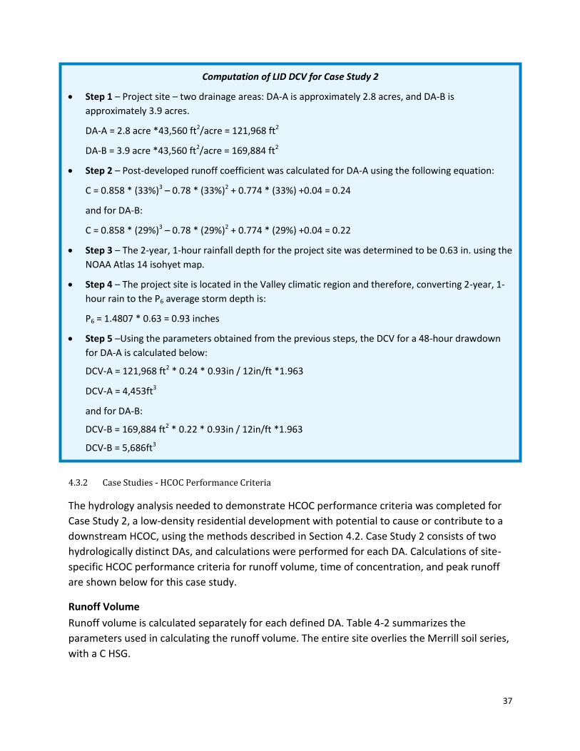
37
4.3.2 Case Studies - HCOC Performance Criteria
The hydrology analysis needed to demonstrate HCOC performance criteria was completed for
Case Study 2, a low-density residential development with potential to cause or contribute to a
downstream HCOC, using the methods described in Section 4.2. Case Study 2 consists of two
hydrologically distinct DAs, and calculations were performed for each DA. Calculations of site-
specific HCOC performance criteria for runoff volume, time of concentration, and peak runoff
are shown below for this case study.
Runoff Volume
Runoff volume is calculated separately for each defined DA. Table 4-2 summarizes the
parameters used in calculating the runoff volume. The entire site overlies the Merrill soil series,
with a C HSG.
Computation of LID DCV for Case Study 2
Step 1 – Project site – two drainage areas: DA-A is approximately 2.8 acres, and DA-B is
approximately 3.9 acres.
DA-A = 2.8 acre *43,560 ft2/acre = 121,968 ft2
DA-B = 3.9 acre *43,560 ft2/acre = 169,884 ft2
Step 2 – Post-developed runoff coefficient was calculated for DA-A using the following equation:
C = 0.858 * (33%)3 – 0.78 * (33%)2 + 0.774 * (33%) +0.04 = 0.24
and for DA-B:
C = 0.858 * (29%)3 – 0.78 * (29%)2 + 0.774 * (29%) +0.04 = 0.22
Step 3 – The 2-year, 1-hour rainfall depth for the project site was determined to be 0.63 in. using the
NOAA Atlas 14 isohyet map.
Step 4 – The project site is located in the Valley climatic region and therefore, converting 2-year, 1-
hour rain to the P6 average storm depth is:
P6 = 1.4807 * 0.63 = 0.93 inches
Step 5 –Using the parameters obtained from the previous steps, the DCV for a 48-hour drawdown
for DA-A is calculated below:
DCV-A = 121,968 ft2 * 0.24 * 0.93in / 12in/ft *1.963
DCV-A = 4,453ft3
and for DA-B:
DCV-B = 169,884 ft2 * 0.22 * 0.93in / 12in/ft *1.963
DCV-B = 5,686ft3

38
Table 4-2. Case Study 2 Calculation of Area-Weighted Curve Number
Land Cover Units DA-A DA-B
Pre-developed Post-developed Pre-developed Post-developed
Open Brush with Good Cover
CN 75 75 75 75
Area (sq. ft) 92,129 9,917 126,848 39,518
Open Brush with Fair Cover
CN 77 77 77 77
Area (sq. ft) 30,710 0 42,283 0
Residential Landscaping CN 69 69 69 69
Area (sq. ft) 0 72,540 0 80,984
Pavement CN 98 98 98 98
Area (sq. ft) 0 22,382 0 21,628
Rooftop CN 98 98 98 98
Area (sq. ft) 0 18,000 0 27,000
Area-weighted CN CN 76 79 76 79
Case Study 2 - Runoff Volume Calculation
Step 1 - Calculate Site CN (see Table 4-2). Calculations of the CN for the pre-developed site assume 75
percent Open Brush with Good Cover (75) and 25 percent Open Brush with Fair Cover (77).
Site CNpre = [ ( 75 * 218,977 ) + ( 77 * 72,993 ) ] / 291,970 = 76
DA-A CNpost = [ ( 75 * 9,917 ) + ( 69 * 72,540 ) + { 98 * ( 22,382 + 18,000 ) } ] / 122,839 = 79
DA-B CNpost = [ ( 75 * 39,518 ) + ( 69 * 80,984 ) + { 98 * ( 21,628 + 27,000 ) } ] / 169,131 = 79
Step 2 - Calculate Soil Storage Capacity (S) and Initial Abstraction (Ia)
DA-A & DA-B (Pre-developed) SA/Bpre = 1,000 / 76 – 10 = 3.2 ; Ipre = 0.2 * 3.2 = 0.64 in
DA-A (Post-developed) SAPost = 1,000 / 79 – 10 = 2.7; IAPost = 0.2 * 2.7 = 0.53 in
DA-B (Post-developed) SBPost = 1,000 / 79 – 10 = 2.7; IBPost = 0.2 * 2.7 = 0.53 in
Step 3. Compute pre-development and post-development runoff volume and calculate required
volume reduction to meet HCOC performance criteria.
DA-A
Pre-developed: VAPre = 1/12 * 122,839 * ( 2.88 – 0.64 )2 / ( 2.88 – 0.64 + 3.2) = 9,442 ft3
Post-developed: VAPost = 1/12 * 122,839 * ( 2.88 – 0.53 )2 / ( 2.88 – 0.53 + 2.7) = 11,194 ft3
Volume reduction: VA-HCOC = 0.95 * 11,194 – 9,442 = 1,193 ft3
DA-B
Pre-developed: VBPre = 1/12 * 169,131 * ( 2.88 – 0.64 )2 / ( 2.88 – 0.64 + 3.2) = 13,000 ft3
Post-developed: VBPost = 1/12 * 169,131 * ( 2.88 – 0.53 )2 / ( 2.88 – 0.53 + 2.7) = 15,413 ft3
Volume reduction: VB-HCOC = 0.95 * 15,413 – 13,000 = 1,642 ft3

39
Case Study 2 – Time of Concentration Calculation
Step 1 – Estimate longest flow length
Use GIS elevation data to estimate the maximum flow length and change in elevation for each of the
DA for pre- and post- developed site conditions.
Step 2 – The total area of the case study is less than 10 acres. Therefore, the nomograph in Appendix
C-1 provided the time of concentration for each DA. The nomograph requires the predominant land
cover type for each DA. Parameters used in the nomograph and time of concentration results are
shown below:
DMA Landuse Flow
Length (ft)
Change in elevation
(ft)
Time of Concentration
(min)
Pre-developed Undeveloped Good Cover
669 2 40
Post-developed DA A
Single-Family Residential
911 2 20
Post-developed DA B
Single-Family Residential
1000 2 21

40
Case Study 2 – Peak Runoff Calculation
Step 1 – Use nomograph in Appendix C-3 to calculate infiltration capacity of soils, Fp, for each DA
assuming AMC II for both pre- and post- developed conditions. Multiply resulting Fp with pervious
fraction (ap) in project to calculate depth of rain to be infiltrated, Fm. Do this for all pervious areas
and sum all Fm values to obtain total Fm value for each DA.
Compute DA infiltration depth, Fm
DA-A DA-B
Pre-developed
Post-developed
Pre- developed
Post-developed
Surface Description: Open Brush
Pervious Area CN 76 75 76 75
Antecedent Moisture Condition 2 2 2 2
Infiltration Capacity Fp (in/hr) 0.44 0.46 0.44 0.46
Pervious Fraction ap 1 0.08 1 0.23
Infiltration depth (in) 0.44 0.04 0.44 0.11
Surface Description: Residential Landscaping (only in post-developed
condition)
Pervious Area CN
69
69
Antecedent Moisture Condition
2
2
Infiltration Capacity Fp (in/hr)
0.56
0.56
Pervious Fraction ap
0.59
0.48
Infiltration depth (in)
0.33
0.27
Total Depth of Infiltration Fm (in/hr)
0.44 0.37 0.44 0.38
Step 2 – Calculate rainfall intensity for each DA for duration equal to the time of concentration
under pre- and post- developed conditions by extrapolating from the 2-year, 1-hr rainfall intensity
for the site. For Case Study 2, the 2-year, 1-hr rainfall intensity is 0.63 in/hr. Due to the site being
located in the Valley climatic region, extrapolation used a Slog-log of 0.6.
DA-A
Pre-developed: IAPre = 10^[ LOG 0.63 – 0.6 * LOG ( 40 / 60) ] =0.80
Post-developed: IAPost = 10^[ LOG 0.63 – 0.6 * LOG ( 20 / 60) ] = 1.22
DA-B
Pre-developed: IBPre = 10^[ LOG 0.63 – 0.6 * LOG ( 40 / 60) ] =0.80
Post-developed: IBPost = 10^[ LOG 0.63 – 0.6 * LOG ( 21 / 60) ] = 1.18

41
Case Study 2 – Peak Runoff Calculation (cont.)
Step 3 – Calculate peak runoff for each DA.
DA-A
Pre-developed: Qp,APre = 0.9 * ( 0.8 – 0.44 ) * 122,839 ft2 / 43,560 ft2/acre = 0.91 cfs
Post-developed: Qp,APost = 0.9 * ( 1.22 – 0.37 ) * 122,839 ft2 / 43,560 ft2/acre = 2.16 cfs
DA-B
Pre-developed: Qp,BPre = 0.9 * ( 0.8 – 0.44 ) * 169,131 ft2 / 43,560 ft2/acre = 1.26 cfs
Post-developed: Qp,BPost = 0.9 * ( 1.18 – 0.38 ) * 169,131ft2 / 43,560 ft2/acre = 2.81 cfs
Step 4 – A confluence analysis is needed to compute peak runoff because the site is divided into
hydrologically independent DA. For pre-developed conditions, it is assumed both DA have the
same time of concentration and therefore the values are added together:
Qp,pre = 0.91 + 1.26 = 2.17 cfs
For post-developed conditions, DA-B has a greater peak runoff and time of concentration then DA-
A, therefore peak runoff at the project site discharge point is calculated as follows:
Qp,post = 2.81 + 2.16 * (1.18 – 0.37 ) / ( 1.22 – 0.37) = 4.87 cfs
Step 5 –The pre-developed peak runoff is subtracted from the post-developed peak runoff to
calculate the required peak runoff reduction to meet HCOC performance criteria:
Qp-HCOC = 0.95 * 4.88 – 2.17 = 2.47 cfs
42
Section 5 – Low Impact Development BMP Evaluation and Selection
5.1 Introduction
The extent to which LID practices may be incorporated into a Priority Project can be determined
once the project proponent has a clear understanding of project conditions based on the
information developed under Section 3, and the applicable performance criteria determined as
described in Section 4. Using this information, LID practices are selected and evaluated to meet
the minimum performance criteria feasible. If it is not feasible to fully meet the performance
criteria utilizing BMPs, as described in this Section, a Project Proponent must then evaluate and
propose an Alternative Compliance approach as described in Section 6.
LID practices may be divided into two general categories:
Preventive measures are site planning, design and construction practices that focus on
minimizing the amount of land disturbed and retaining, to the maximum extent
practicable, the natural drainage characteristics of the site. Consideration of preventive
measures begins early in the project planning phase, when the layout of the project site is
being contemplated. The extent to which such measures are incorporated into the project
site dictate to a large degree the extent to which additional mitigative measures will be
required to meet the performance criteria. Maximizing preventative measures will reduce
additional mitigation requirements, resulting in a more cost effective project.
Mitigative measures, if required, are structural BMPs that manage impacts from
stormwater runoff and provide pollutant reduction. Categories of mitigative BMPs that
must be considered in order of priority are: (1) infiltration BMPs; (2) BMPs that harvest
and use runoff (e.g., rain barrels, cisterns, etc); and (3) vegetated BMPs that promote
evapotranspiration (e.g., bioretention, biofiltration, and biotreatment).
Table 5-1 summarizes how preventive and mitigative measures interrelate and how WQMP
development addresses each category. The following sections describe requirements for
incorporation of both categories into the planning and design of a project.
The purpose of this section is to provide guidance for preparing site designs and drainage plans,
selecting and sizing BMPs applicable to the project as prescribed in the MS4 Permit, and
evaluating the conformance of the proposed BMPs with project-specific LID performance
criteria. Final construction documents prepared during project design are the appropriate place
to establish construction phase requirements that will then be enforced during construction.
Furthermore, detailed requirements for stormwater quality protection during construction are
covered under the Sections X.B and XIV of the MS4 Permit. Establishing appropriate post-

43
construction measures and mechanisms for ensuring that they will be implemented are
discussed in Section 8.
5.2 Selection of LID Preventive Measures
Consistent with the MS4 Permit, the LID practices incorporated into a project-specific WQMP
should promote the following principles, where feasible:
Incorporate landscape designs that promote water retention and evapotranspiration,
such as through soil development and grading techniques, and incorporation of water
conservation elements such as use of native plants;
Include permeable surface designs in parking lots and areas with low traffic;
Allow natural drainage systems for street construction and catchments (with no drainage
pipes), and allow grassy swales and ditches;
Require parking lots to drain to landscaped areas to provide treatment, retention, or
infiltration;
Reduce curb requirements where adequate drainage, conveyance, treatment and storage
are available to allow stormwater to drain into landscaped areas;
Incorporate rainwater harvesting and use;
Allow building of narrow streets and provide alternatives to minimum parking
requirements;
Consider vegetated landscape as an integral element of streets, parking lots, playgrounds
and buildings as a stormwater treatment and retention system; and
Table 5-1. Application of LID Practices to Development Phases Project
Development Phase
LID Practice
Preventive Measures Mitigative Measures
Site Planning and layout
Preserve natural infiltration capacity Preserve existing drainage patterns Protect existing vegetation and sensitive
areas
Not applicable, but extensive application of preventive measures will reduce the mitigative measures required below
Site and Project Design
Minimize impervious area Disconnect impervious areas
Infiltration BMPs Capture/Use BMPs Vegetated BMPs
Construction Minimize construction footprint Minimize unnecessary compaction Minimize removal of native vegetation
Re-vegetate disturbed areas
Post-Construction Implement source control BMPs Restore original soils and use appropriate
vegetation
Maintain BMPs appropriately
Source: Adapted from SoCal LID manual (original source: Low Impact Development Center, Inc.)

44
Case Study 2 Application of Preventative Site
Design Principles
Consider and facilitate application of landform grading techniques and revegetation as an
alternative to traditional approaches, particularly in areas susceptible to erosion and
sediment loss such as hillside development projects.
Extensive application of preventive
measures throughout the development
will reduce the number and size of
mitigative BMPs required to meet WQMP
requirements. The earlier in the project
development phase that preventive
measures are considered, the easier it will
be to incorporate them.
Preventive measures are incorporated into
all phases of a project. Initially, these
measures are considered during the
planning phase to identify ways to reduce
the project footprint, minimize land
disturbance and maintain the pre-
development hydrological function of a
new development site, or, at a minimum,
to maintain the existing hydrologic
function of a site being redeveloped.
Preventive measures must also be considered and included during both the construction and
post-construction phases of the project. Unless carefully anticipated and prescribed in
construction document requirements, construction activity can reduce the benefits
incorporated during earlier phases, such as by disturbing or compacting naturally infiltrating
soils in an area that was set aside for preservation. It is vital that the project incorporate
revegetation requirements to cover exposed soils and allow for the site to maximize
stormwater retention as quickly as possible following completion of construction activities.
The following sections provide additional information regarding the key elements associated
with the incorporation of preventive measures into the various phases of a project – from
conception to completion.
5.2.1 Site Planning and Design Practices
Preventive measures associated with site planning and design will be considered together as
the practicability of a particular design may be determined by site plan characteristics. Table 5-
2 summarizes the key elements that should be considered during the site planning and design
phases.
Preventive measures apply to both new development and significant redevelopment projects.
However, it is recognized that the ability to incorporate preventive measures into an existing
Preserve existing
drainage pattern
Protect existing
vegetation
Minimize impervious area (use
of shortened driveways)
Disconnect
impervious area
(roof drains to
bioswale)

45
developed site undergoing redevelopment can be more difficult. Attention to specific types of
preventive measures, such as minimizing new impervious area and disconnecting existing
impervious areas can provide substantial stormwater management benefits.
The following sections provide a description of each preventive measure listed in Table 5-2. For
additional information and links to additional technical resources, consult the Low Impact
Development Manual for Southern California: Technical Guidance and Site Planning Strategies
(www.casqa.org/LID/SoCalLID/tabid/218/Default.aspx), or Maryland Department of Resource
Programs and Planning Division. Low-Impact Development Design Strategies -An Integrated
Table 5-2. LID Preventive Measures for Consideration During Site Planning and Design Phases
LID - Preventive Measures
Project Phase
Planning Design
Maximize natural infiltration capacity
Avoid locating constructed elements on highly permeable areas
Cluster constructed elements in the least permeable areas
Use alternative permeable or porous building materials where allowed by code
Preserve existing drainage patterns and increase time of concentration
Avoid channelization of natural drainages Where channel engineering is necessary,
include sinuosity to increase time of concentration
Establish setbacks and buffer areas from natural waterbodies
Retain natural depressions in project area
Avoid channelization of natural streams
Where channel engineering is necessary:
Include mild slopes, Increase channel roughness to
increase time of concentration Use pervious channel linings to
increase infiltration
Protect existing vegetation and sensitive areas
At the outset, establish areas within project site that should remain undisturbed
Establish setbacks and buffer zones around sensitive areas
Incorporate rather than eliminate established vegetation throughout site layout
Design site layout to protect sensitive areas
Minimize impervious area
Reduce footprint by: Building vertically rather than horizontally Reducing road and sidewalk widths to MEP Clustering constructed elements to preserve
open space Minimizing lot setbacks to reduce driveway
lengths
Install sidewalks only one side of private roadways
Use alternative permeable or porous building materials where allowed by code
Reduce overall parking lot size by creating smaller parking spaces for compact cars
Disconnect impervious areas
Plan site layout and mass grading to allow runoff to be directed to permeable areas, e.g., natural retention areas, open spaces, medians, parking islands, planter boxes
Avoid channelization of natural on-site streams
Incorporate permeable areas throughout project site to accept runoff
Design roof downspouts to drain to pervious areas
Use alternative permeable or porous building materials where allowed by code
Integrated with planning
Incorporate preventive measures that are consistent with the Watershed Action Plan
Determine if any approved regional BMP projects are constructed downstream and included in WAP, prior to site design planning
Use all design requirements included in the Watershed Action Plan for watershed based BMPs
Source: Adapted from SoCAL LID manual (original source: Low Impact Development Center, Inc)

46
Design Approach (http://www.co.pg.md.us/Government/DER/PPD/pgcounty/lidmain.htm), or
Orange County, CA stormwater program guidance documents
(http://www.waterboards.ca.gov/rwqcb8/water_issues/programs/stormwater/oc_permit.shtml).
5.2.1.1 Maximize Natural Infiltration Capacity
Taking advantage of a site’s natural infiltration and water storage capacity decreases the
volume of stormwater runoff generated and the need for BMPs that mitigate project impacts.
Accordingly, when developing the footprint for constructed elements of a proposed project,
areas where infiltration could be maximized should be preserved. Typically, these areas include:
Hydrologic Soil Groups A or B
Mild slopes or depressions
Undeveloped portions of an existing site undergoing redevelopment
Selecting areas to maximize infiltration must consider geotechnical hazards that could be
created by infiltration in inappropriate locations, such as near structures, which may cause
structural failure, or in and around steep slopes, which may cause slope destabilization.
5.2.1.2 Preserve Existing Drainage Patterns and Increase Time of Concentration
A project site should be evaluated to determine how rainfall naturally moves through or is
stored on the site. To the extent practicable, the natural drainage flow-through and storage
characteristics should be incorporated into the project layout. Preserving these features will
help maintain the site’s pre-development hydrologic characteristics, including the time of
concentration, runoff velocity, and peak flow volume. In addition to preserving natural features,
the project site should be evaluated to determine where site grading could add additional
depressions that can provide on-site storage of stormwater runoff.
5.2.1.3 Protect Existing Vegetation and Sensitive Areas
Vegetative cover (extent, depth and density) provides additional storage volume during rainfall
events. Soils with undisturbed vegetation have a much higher capacity to store and infiltrate
runoff than disturbed soils or vegetation. Every effort should be made to minimize soil and
vegetation disturbance (including existing trees) to retain on-site storage capacity.
Projects should avoid sensitive areas, including wetlands, streams, floodplains, and intact
wooded areas. Not only do federal, state and local laws already limit development in these
areas or require compliance with significantly more stringent regulatory requirements, impacts
to these areas can greatly impact the pre-development hydrologic characteristics of a site.
5.2.1.4 Minimize Impervious Areas
Increased imperviousness is associated with increased environmental impacts to downstream
receiving waters, including the creation of hydrologic conditions of concern. Accordingly,
projects site plans should minimize impervious areas, which will greatly reduce the amount of
BMPs needed to mitigate potential downstream impacts. Table 5-2 includes several example

47
techniques for reducing imperviousness. The extent to which some of these techniques may be
employed in the local area (e.g., minimum road widths) is dependent on existing codes and
ordinances, which should be carefully consulted in coordination with the local jurisdiction.
5.2.1.5 Disconnect Impervious Areas
Disconnection of impervious areas so that stormwater runoff is directed to on-site pervious
surfaces rather than off-site streets and storm drains increases the time of concentration,
reduces the peak discharge rate from the site, and maximizes opportunities for on-site
infiltration. Careful application of this preventive measure can greatly reduce the need for
other BMPs. Care must be taken to ensure that runoff to pervious areas for on-site infiltration
does not create geotechnical hazards or cause impacts to adjacent properties. The extent to
which disconnection practices may be employed on the project site may be dependent on
existing codes and ordinances, which should be carefully consulted.
5.2.1.6 Integrate with Watershed Planning
Regional efforts to manage watersheds in an integrated manner are underway in San
Bernardino County through the development of a Watershed Action Plan. This planning effort
may influence requirements applicable to site planning and design.
5.2.2 Construction Practices
Project proponents should thoroughly evaluate how the planned construction activity will be
staged and phased, and the construction activities allowed or specified throughout the planning
and design phases of a project. Table 5-3 summarizes the construction practices that should be
considered when incorporating preventive measures into the project during site planning and
design. For example, if minimizing land disturbance is a key element of the project plan, then it
is important to consider how construction activities, including siting of staging and laydown
areas, can be performed without impacting areas where no disturbance is desired. In addition,
during construction the following preventive measures should be considered:
Minimize size of construction easements;
Locate material storage areas and stockpiles within area being developed;
Limit ground disturbance in areas not requiring grading;
Delineate access routes for heavy equipment; and
Delineate areas to remain undisturbed.
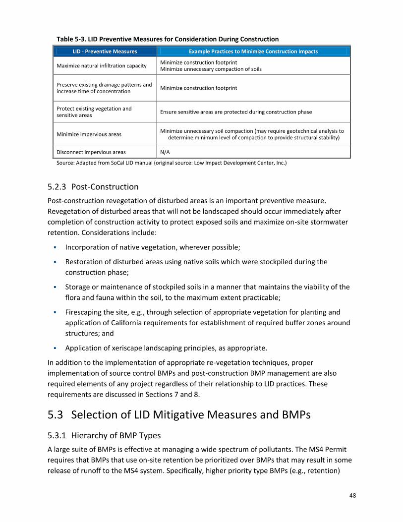
48
Table 5-3. LID Preventive Measures for Consideration During Construction
LID - Preventive Measures Example Practices to Minimize Construction Impacts
Maximize natural infiltration capacity Minimize construction footprint Minimize unnecessary compaction of soils
Preserve existing drainage patterns and increase time of concentration
Minimize construction footprint
Protect existing vegetation and sensitive areas
Ensure sensitive areas are protected during construction phase
Minimize impervious areas Minimize unnecessary soil compaction (may require geotechnical analysis to
determine minimum level of compaction to provide structural stability)
Disconnect impervious areas N/A
Source: Adapted from SoCal LID manual (original source: Low Impact Development Center, Inc.)
5.2.3 Post-Construction
Post-construction revegetation of disturbed areas is an important preventive measure.
Revegetation of disturbed areas that will not be landscaped should occur immediately after
completion of construction activity to protect exposed soils and maximize on-site stormwater
retention. Considerations include:
Incorporation of native vegetation, wherever possible;
Restoration of disturbed areas using native soils which were stockpiled during the
construction phase;
Storage or maintenance of stockpiled soils in a manner that maintains the viability of the
flora and fauna within the soil, to the maximum extent practicable;
Firescaping the site, e.g., through selection of appropriate vegetation for planting and
application of California requirements for establishment of required buffer zones around
structures; and
Application of xeriscape landscaping principles, as appropriate.
In addition to the implementation of appropriate re-vegetation techniques, proper
implementation of source control BMPs and post-construction BMP management are also
required elements of any project regardless of their relationship to LID practices. These
requirements are discussed in Sections 7 and 8.
5.3 Selection of LID Mitigative Measures and BMPs
5.3.1 Hierarchy of BMP Types
A large suite of BMPs is effective at managing a wide spectrum of pollutants. The MS4 Permit
requires that BMPs that use on-site retention be prioritized over BMPs that may result in some
release of runoff to the MS4 system. Specifically, higher priority type BMPs (e.g., retention)

49
must be evaluated for feasibility (see Section 5.4), selected and sized to capture the maximum
feasible portion of the DCV, before attempting to address the remaining volume with the next
lower control (e.g., biotreatment). Section 5.3.2 describes site-specific conditions that would
require or allow for a project WQMP to determine that it is not feasible to consider retention
and infiltration BMPs, and proceed to evaluate biotreatment BMPs.
Figure 5-1 provides a flowchart showing the BMP selection and evaluation process that must be
followed in developing a WQMP. The following sections provide guidance on the selection of
specific BMPs and methods for evaluating conformance with project–specific performance
criteria. General steps involved in BMP selection and evaluation are summarized below:
Step 1 - Incorporate hydrologic source control into site design
The first step in the process is to consider hydrologic source control (HSC). HSC is a class of
BMPs integrated with site design that retain stormwater runoff and reduce the volume
(and potentially the rate) of stormwater discharge to the downstream system (e.g.
impervious area dispersion). If the volume of runoff retained by HSC in a DA is greater
than or equal to the DCV for the DA, the DA is considered to be self-retaining and no
additional BMPs are required to treat discharges from the drainage area to meet LID
requirements. Otherwise, the volume retained by HSC is subtracted from the DCV to
estimate the remaining volume for sizing LID infiltration BMPs. However, the excess
volume retained by the HSC could be used to provide additional volume mitigation that
may be required to meet HCOC performance criteria.
Step 2 – Evaluate on-site retention and infiltration BMPs
The next step is to determine the feasibility of retention and infiltration BMPs (Sections
5.3.2.1 and 5.5.1). If on-site retention and infiltration is infeasible the project proponent
shall proceed to Step 3.
Step 3 – Evaluate harvest and use BMPs
The next step is to determine the feasibility of harvest and use BMPs (Sections 5.3.2.2 and
5.5.4). If implementation of harvest and use BMPs is infeasible the project proponent shall
proceed to Step 4.
Step 4 – Re-Evaluate and Optimize suite of BMPs to maximize on-site retention of DCV
If individual retention and infiltration, and/or harvest and use BMP are feasible, but
unable to treat the entire DCV, evaluate the use of combinations of BMPs, including HSC
BMPs, to maximize on-site retention of the DCV. If no combination of BMP can mitigate
the entire DCV, implement the single BMP type, or combination of BMP types, that
maximizes on-site retention of the DCV, and proceed to Step 5.
Step 5 – Evaluate BMPs for biotreatment of pollutants of concern
If it is infeasible to fully infiltrate the DCV on the project site, then biotreatment BMPs
must be selected and implemented to mitigate the entire remaining DCV (Sections 5.3.2.4

50
and 5.5.5). Biotreatment BMPs with medium to high pollutant removal effectiveness must
be selected to address the project pollutants of concern (POC) that cause impairment of
downstream receiving waters. If the combination of retention and infiltration, harvest and
use, and biotreatment is insufficient to capture and treat the full DCV, proceed to Step 6.
Step 6 – Determine alternative compliance strategies
Lastly, if it is infeasible to fully infiltrate, retain or biotreat the DCV on the project site,
then Section 6 provides guidance for identifying alternative compliance approaches.
5.3.2 General Feasibility Criteria for Use of Required LID BMPs
Prior to BMP selection, the WQMP must substantiate whether any or all BMPs are feasible to
consider for use on a particular site, or whether use of one or more BMP types would result in
violations of statutory requirements. The WQMP must include justification for any infeasibility
determination. The following subsections describe specific conditions that would make the use
of a specific BMP type infeasible for consideration when developing a project WQMP.

51
Select and Evaluate Runoff Capture in
Infiltration BMPs
On-site Retention/Infiltration is infeasible
LID DCV
Fulfilled?
Select and Evaluate Runoff Capture in
Hydrologic Source Control BMPs
Select and Evaluate Runoff Capture In
Harvest and Use BMPs
LID DCV
Fulfilled?
LID DCV
Fulfilled?
No
Yes
Yes
No
Yes
No
No
Select and Evaluate Runoff Capture in
Volume Based Biotreatment BMPs
LID DCV
Fulfilled?Yes
Select and Evaluate Runoff Capture in
Flow Based Biotreatment BMPs
LID DCV
Fulfilled?
No
No
Develop an Alternative Compliance Plan
for Remaining LID DCV (Section 6)
Incorporate On-site LID BMPs into Final
WQMP
Yes
Yes
Figure 5-1 On-site LID BMP Selection and Evaluation Flowchart
5.3.2.1 Infiltration BMPs
All projects retaining and infiltrating runoff shall implement source control and pollutant
prevention control BMPs, to the MEP, in order to protect groundwater quality. Conditions that
would prohibit the use of infiltration BMPs for a specific project WQMP are listed below:

52
Stormwater infiltration would result in significant risks to drinking water quality and
groundwater quality that cannot be reasonably and technically mitigated. Factors that
may pose a risk to groundwater quality that cannot be mitigated include:
Seasonally high groundwater is less than 10 feet below the designed bottom of the
infiltration facility for aquifers managed for water quality or with significant
connectivity to aquifers managed for groundwater quality.
Seasonally high groundwater is less than 5 feet below the designed bottom of the
infiltration facility for aquifers not managed for groundwater quality and without
significant connectivity to aquifers managed for groundwater quality.
Horizontal distance to a water supply well is less than 100 feet.
Infiltration of stormwater from project land uses would result in significant risks to
drinking water quality and groundwater quality that cannot be reasonably and
technically mitigated through methods such isolation of sources and/or pre-treatment
of runoff prior to infiltration.
For Brownfield sites or adjacent sites, stormwater infiltration would result in a significant
risk of mobilizing or moving contamination that cannot be reasonably and technically
avoided, as documented by a site-specific or available watershed study with sufficient
resolution to positively identify areas where stormwater infiltration should not be
conducted. The documenting study shall have sufficient resolution to positively identify
areas where stormwater infiltration should be restricted.
Where a groundwater pollutant plume (man-made or natural) is under the site or in close
proximity, and stormwater infiltration would result in a significant risk of causing or
contributing to plume movement that cannot be reasonably and technically avoided, as
documented by a site-specific study or available watershed study. The documenting study
shall have sufficient resolution to positively identify areas where stormwater infiltration
should be restricted.
Projects constructing fueling operations, large commercial parking lots, areas of industrial
or light industrial activity, areas subject to high vehicular traffic (25,000 or more daily
volume), car washes, fleet storage areas, nurseries, or any other land use or activity with a
high threat to water quality, unless adequate pretreatment is provided.
Infiltration of runoff into Class V injection wells or drywells, in projects occupied by
vehicular repair or maintenance activities, such as auto body repair, automotive repair,
new and used car dealerships, specialty repair shops (e.g. transmission and muffler repair)
or any facility that performs vehicular repair work.
Stormwater infiltration would result in significantly increased risks of geotechnical hazards
such as liquefaction or landslides that cannot be reasonably and technically mitigated as
documented by a geotechnical professional or available watershed study. The

53
documenting study shall have sufficient resolution to positively identify areas of expansive
clays or other conditions, which would prohibit stormwater infiltration.
Infiltration of site runoff would create a nuisance or pollution as defined in Water Code
Section 13050 (http://www.leginfo.ca.gov/cgi-
bin/displaycode?section=wat&group=13001-14000&file=13050-13051).
Infiltration of runoff would violate downstream water rights.
Certain factors may limit the potential benefit that infiltration BMPs can have or limit the extent
to which infiltration is beneficial. While these factors eliminate the requirement to consider
BMPs with a primary purpose of infiltration, these factors shall not prevent the ability of the
project proponent to consider some level of incidental infiltration, if desired, as part of an
integrated stormwater management design.
Infiltration is not required to be considered if any of the following conditions are met:
Project is located in D soils per the watershed Geodatabase and the site geotechnical
investigation confirms presence of soil characteristics, which support categorization as D
soils. For small projects (residential projects under 10 acres in size and comprised of less
than 30 dwelling units; commercial projects less than 5 acres in size, and industrial
projects less than 2 acres in size), the geotechnical investigation shall not be required to
include infiltration testing to confirm mapped categorization as D soils; other sources of
data such as bore logs, soils reports and other related information from the site, or from
other sites in the immediate vicinity obtained for other purposes may be used.
The measured infiltration rate after accounting for soil amendments is less than 0.3 inches
per hour in the vicinity of proposed BMPs. Infiltration measurement shall include
protocols that account for the effect of soil amendments. Soil amendments would not be
expected to increase the effective infiltration rate of a soil if the limiting horizon for
infiltration lies below the amended zone (in this case, it would increase storage, but not
infiltration rate). Soil amendments would be expected to effectively increase infiltration
rates if the limiting horizon for infiltration occurs near the proposed bottom of the
infiltration basin and the entire depth of this layer can be amended.
Reduction of runoff to pre-developed conditions would be partially or fully inconsistent
with watershed-scale management strategies and/or would impair the beneficial uses of
the receiving water. The allowable level of runoff reduction must be documented in a site-
specific study or watershed plan, and it must be demonstrated that infiltration BMPs
would exceed the allowable level of runoff reduction.
Increase in infiltration to pre-developed conditions would be partially or fully inconsistent
with watershed-scale management strategies and/or would cause impairments to
downstream beneficial uses, such as change of seasonality of ephemeral washes. The
level of allowable increase in infiltration must be documented in a site-specific study or
watershed plan, and it must be demonstrated that stand-alone infiltration BMPs would

54
exceed the allowable level of increase in infiltration or what level could be infiltrated as a
partial consideration.
In the event that any of these conditions apply, infiltration BMPs are not required, but may be
considered as an option. Biotreatment BMPs (where employed) should be designed to promote
incidental infiltration where possible.
5.3.2.2 Harvest and Use BMPs
A single ‘yes’ answer to any of the following questions indicates that harvest and use shall not
be considered because harvest and use would conflict with codes and/or ordinances or is
impractical:
Does use of harvested water for the type of demand on the project violate codes or
ordinances in effect at the time of project application?
Would harvest and use of runoff violate downstream water rights?
Is recycled water planned for use to serve the project site non-potable demand?
5.3.2.3 Evapotranspiration BMPs
In general, evapotranspiration (ET) would not be expected to cause a risk that would exclude its
use from any project.
Green roofs, brown roofs, and blue roofs may be considered wherever they are consistent with
applicable codes and ordinances. However, the use of these BMPs is presently considered
above and beyond the MEP; and, therefore, these BMPs are encouraged but not required to be
considered in assessing feasibility. Green roofs, brown roofs, and blue roofs are considered to
be beyond the MEP for the following technical, economical, and societal reasons:
The increased use of irrigation water and plant life requiring water is inappropriate to the
direction of state legislation (AB1881) mandating landscaping water efficiency.
Long term data regarding maintenance of a green roof, in a Mediterranean climate prone
to high winds and fire hazard is not readily available.
The practical limitations of requiring individual homeowners and small business owners to
irrigate and maintain a green roof are untested.
The majority of current building codes and the fire code do not specifically address green
roof construction, and it is unknown how this requirement may conflict with other
building code provisions or upcoming mandatory solar requirements.
Studies of cost-benefit and cost-effectiveness of green roofs have often not considered
costs of additional structural requirements, which may comprise a large portion of green
roof costs.
Although green roofs have been encouraged in several locations across the country, there
are no known locations in the US where implementation of greenroofs has been required
in an implemented permit in order to meet the MEP standard.

55
Where green roofs, brown roofs and blue roofs are selected as an option, consideration should
be given for overall water demands which may increase as a result of an increase in the amount
of area potentially requiring irrigation during the dry periods. However, for a project with very
high density, green roofs could provide almost complete treatment for the water quality design
storm (sidewalks and minor surface areas would also need treatment) and, for some projects,
could provide a cost-saving when other benefits (heating and cooling reductions, etc.) are
factored in.
5.3.2.4 Biotreatment BMPs
In general, biotreatment BMPs would not be expected to cause a risk that would exclude their
use from any project. However, biotreatment BMPs shall be designed to prevent or limit
incidental infiltration for projects where use of infiltration BMPs would be prohibited (see
Section 5.3.2.1).
5.4 Evaluation of LID BMPs
When evaluating the effect of proposed BMPs on the post-development hydrologic condition, it
is necessary to calculate the runoff capture provided by all volume mitigation BMPs proposed in
the WQMP. This section provides methodologies for estimating runoff capture for specific
BMPs designed to infiltrate, harvest and use, evapotranspire, and/or biotreat runoff. The BMPs
include:
Hydrologic Source Control (HSC) BMPs – Impervious area dispersion, localized on-lot
infiltration, green/brown/blue roof, street trees, and residential rain barrels/cisterns
Infiltration BMPs - Infiltration trench, infiltration basin, bioretention with no underdrain,
drywell, permeable pavement, and underground infiltration
Harvest and Use BMPs – Cisterns and underground detention
Biotreatment BMPs – Bioretention with underdrain, vegetated swale, vegetated filter
strip, dry extended detention basin, wet detention basin, constructed wetland, and
proprietary biotreatment.
5.4.1 Hydrologic Source Control
HSC BMPs are differentiated from retention and biotreatment classes of BMPs by their higher
level of integration within a site. They are not sized according to engineering design criteria,
and they do not typically result in a distinct facility. Consequently, they are usually regarded as
site design practices, as opposed to structural BMPs. On-site retention of runoff in HSC BMPs
reduces the portion of the DCV that must be addressed in downstream BMPs. HSC BMPs that
are considered to retain runoff include:
Impervious area dispersion
Localized on-lot infiltration
Green / brown roof
Blue roof

56
Street trees
Residential rain barrels/cisterns
5.4.1.1 Impervious Area Dispersion
Impervious area dispersion refers to the practice of routing runoff from impervious areas, such
as rooftops, walkways, and patios onto the surface of adjacent pervious areas. Rooftop
downspout disconnection is an example of commonly used impervious area dispersion BMPs.
Runoff is dispersed uniformly via splash block or dispersion trench and soaks into the ground as
it moves slowly across the surface of pervious areas. The retention volume provided by
downspout dispersion is a function of the ratio of impervious to pervious area (Table 5-4).
5.4.1.2 Localized on-lot infiltration
Localized on-lot infiltration refers to the practice of collecting runoff from small distributed
areas within a DA and diverting it to a dedicated on-site infiltration area where it can be
infiltrated or evapotranspired. This technique can include disconnecting downspouts and
draining sidewalks and patios into french drains, trenches, small rain gardens, or other surface
depressions. Localized on-lot infiltration shall meet infiltration infeasibility screening criteria to
be considered for use (see Section 5.3.2.1). The retention volume provided by localized on-lot
infiltration is equal to the storage volume provided by surface ponding and the pore space
within an amended soil layer or gravel trench (Table 5-4).
5.4.1.3 Evapotranspiration: Green, brown, or blue roofs
Green roofs are also known as ecoroofs, roof gardens, or vegetated roof covers. Green roofs
are roofing systems that provide a layer of soil/vegetative cover over a waterproofing
membrane. There are two types of green roofing systems; extensive (a light weight system);
and intensive (a heavier system that allows for larger plants but requires additional
maintenance). A green roof mimics pre-development conditions by limiting the impervious area
created by development. Green roofs filter, absorb, and evapotranspire precipitation to help
mitigate the delivery of excess runoff to the local storm water conveyance systems and the
effects of urbanization on water quality.
Brown roofs are essentially a sub-type of green roof designed to maximize biodiversity. Brown
roofs typically utilize natural soil and locally available substrates to create a protected
biodiverse habitat for specific species of local flora and fauna. Rather than landscaping the roof
during construction, plants are left to germinate and grow on their own in the native soils, thus
the “brown” (i.e., initially unvegetated) designation. Hand-seeding may be implemented where
self-colonization via airborne seeds is unlikely.

57
Table 5-4 - Estimation Methods for On-site Retention BMPs
BMP Type Runoff Volume Calculation Variables Fact Sheet Reference for
Design Details
Impervious area dispersion
Vret = DAimp * Rperv:imperv * 0.5/12 DAimp = impervious drainage area (ft2)
Rperv:imperv = ratio of pervious to impervious area
Orange County Technical
Guidance Document (TGD)
for Project WQMPs
Appendix XIV1
Localized on-lot infiltration
Vret = ( SApond * dpond ) +
( SAmatrix * dmatrix * nmatrix )
SApond = surface area for ponding water (ft2)
dpond = depth of ponding water (ft)
SAmatrix = surface area of amended soil / gravel (ft2)
dmatrix = depth of amended soil / gravel (ft)
nmatrix = porosity of amended soil / gravel
Orange County TGD for
Project WQMPs Appendix
XIV1
Green / Brown roofs
Vret = Edaily, wet season * Arooftop * Tdrawdown/24
or
fully self-retaining if dmatrix = 3/RBMP, roof
dmatrix = depth of soil layer for roof BMP (ft) RBMP:roof = ratio of BMP area to total roof area Edaily,wetseason = wet season daily evaporation (in/day) Tdrawdown Arooftop – rooftop area for evapotranspiration BMPs
Orange County TGD for
Project WQMPs Appendices
IX and XIV1
Blue roof Vret = Edaily, wet season * Arooftop * Tdrawdown/24
Edaily,wetseason = wet season daily evaporation (in/day)
Tdrawdown = drawdown time for stored runoff (hrs), default is 96
hours
Arooftop – rooftop area for evapotranspiration BMPs
Orange County TGD for
Project WQMPs Appendix
XIV1
Street trees Vret = ntrees * IAcanopy * dint / 12
ntrees = number of street trees
IAcanopy = average impervious area under tree canopy after 4 years
growth (ft2)
dint = rain depth retained by canopy interception (in)
Orange County TGD for
Project WQMPs Appendix
XIV1
Residential rain barrels / cisterns
Vret = nbarrels * Sbarrel / 2 nbarrels = number of residential rain barrels / cisterns
Sbarrel = volume of residential rain barrels / cisterns (ft3)
Orange County TGD for
Project WQMPs Appendix
XIV1
Infiltration basin
Vret = Pdesign / 12 * SAinf * ( Tdrawdown + Tfill )
Pdesign = design percolation rate (in/hr), field measured infiltration
divided by safety factor
SAinf = infiltrating surface area (ft2)
Tdrawdown = drawdown time for stored runoff (hrs), default is 48
hours1
Tfill = duration of storm when infiltration is occurring as basin is
filling (hrs), default is 3 hours
Riverside County LID BMP Manual
2
Orange County TGD for
Project WQMPs Appendix
XIV1
1 A 48-hour drawdown time is utilized for infiltration basin sizing, which is consistent with the current DCV calculation methodology in Form 4.2-1 of the WQMP Template

58
Table 5-4 (cont.) - Estimation Methods for On-site Retention BMPs
BMP Type Runoff Volume Calculation Variables Fact Sheet Reference for Design Details
Infiltration trench
Vret = ( Pdesign / 12 * SAinf * Tfill ) +
( SAponded * dponded ) +
( SAgravel * dgravel * ngravel )
where dponded < Tdrawdown * Pdesign / 12
Pdesign = design percolation rate (in/hr), field measured infiltration divided by safety
factor
SAinf, ponded,gravel = surface area (ft2) of trench bottom, gravel layer, and surface ponding
Tdrawdown = drawdown time for stored runoff (hrs), default is 48 hours
Tfill = duration of storm when infiltration is occurring as basin is filling (hrs), default is
3 hours
dponded,gravel = depth (ft) of ponding and gravel layers
ngravel = porosity of gravel layer
Riverside County LID BMP Manual
2
Orange County
TGD for Project
WQMPs
Appendix XIV1
Bioretention with no underdrain
Vret = ( Pdesign / 12 * SAinf * Tfill ) +
( SAponded * dponded ) +
( SAsoil * dsoil * nsoil ) +
( SAgravel * dgravel * ngravel )
where dponded < Tdrawdown * Pdesign / 12
Pdesign = design percolation rate (in/hr), field measured infiltration divided by safety
factor
SAinf,ponded,soil,gravel = surface area (ft2) of bioretention bottom, soil and gravel layers,
and surface ponding
Tdrawdown = drawdown time for stored runoff (hrs), default is 48 hours
Tfill = duration of storm when infiltration is occurring as basin is filling (hrs), default is
3 hours
dponded,gravel = depth (ft) of ponding and gravel layers
ngravel = porosity of gravel layer
Riverside County LID BMP Manual
2
Orange County
TGD for Project
WQMPs
Appendix XIV1
Drywell / Permeable pavement / Underground infiltration
Vret = ( Pdesign / 12 * SAinf * Tfill ) +
( SAresevoir * dresevoir * naggregate )
where dresevoir < Tdrawdown * Pdesign / 12
Pdesign = design percolation rate (in/hr), field measured infiltration divided by safety
factor
SAinf,reservoir = surface area (ft2) of reservoir for drywell or permeable pavement,
include weep holes for drywell SAinf
Tdrawdown = drawdown time for stored runoff (hrs), default is 48 hours
Tfill = duration of storm when infiltration is occurring as basin is filling (hrs), default is
3 hours
dreservoir = depth (ft) of drywell
naggregate = porosity of aggregate , if none then 1.0
Riverside County LID BMP Manual
2
Orange County
TGD for Project
WQMPs
Appendix XIV1
1) http://www.waterboards.ca.gov/rwqcb8/water_issues/programs/stormwater/oc_permit.shtml 2) http://rcflood.org/NPDES/LIDBMP.aspx

59
A green or brown roof can be considered to be fully self-retaining if it meets criteria for soil
depth as shown in Table 5-4. By fully retaining water from the roof, the LID DCV should be
recomputed to account for the reduction in imperviousness equal to the area of the roof routed
into the BMP.
Blue roofs, also known as rooftop detention systems, serve as a rooftop storage designed to
reduce runoff peak flows and volumes. Captured stormwater, up to the design depth, is held on
the rooftop until the water either evaporates or is slowly metered out via flow restriction
valves. With sufficent waterproofing blue roofs can be implemented on existing structures,
given that the roof and building are of sufficient structural integrity to support the weight for
the ponded water. As blue roofs lack vegetation, they require significantly less maintenance
than green or brown roofs. Blue roofs should not be designed to hold standing water longer
than 96 hours in order to mitigate vector hazards, and therefore it is not possible for these
BMPs to be fully self retaining. Instead, volume retention is equal to the wet season
evaporation over a 96 hour period (Table 5-4).
5.4.1.4 Street Trees
By intercepting rainfall, trees located in
street medians, shoulders, and parking
lots, can provide several aesthetic and
stormwater benefits including peak flow
control, increased infiltration and
evapotranspiration, and runoff
temperature reduction. The volume of
precipitation intercepted by the canopy
reduces the treatment volume required
for downstream BMPs. Shading reduces
the heat island effect as well as the
temperature of adjacent impervious
surfaces, over which stormwater flows,
and reducing the heat transferred to
downstream receiving waters. Tree roots also strengthen the soil structure and provide
infiltrative pathways, simultaneously reducing erosion potential and enhancing infiltration.
The retention volume provided by street trees via canopy interception is dependent on the tree
species, time of year, and maturity. To compute the retention depth, the expected impervious
area covered by the full tree canopy (IAcanopy) after 4 years of growth must be computed. The
maximum retention depth credit for canopy interception is 0.05 inches over the impervious
area covered by the canopy at 4 years of growth (Table 5-4).
Case Study 1 Application of Street Trees HSC
Project with 114 street trees IAcanopy = 1,000 ft
2
Vret = ntrees * IAcanopy * 0.05 / 12 = 475 ft3

60
5.4.1.5 Residential Rain Barrels/Cisterns
Rain barrels / cisterns are above ground storage vessels that capture runoff from roof
downspouts during rain events and detain that runoff for later uses such as irrigating
landscaped areas. The temporary storage of roof runoff reduces the runoff volume from a
property and may reduce the peak runoff velocity for small, frequently occurring storms. In
addition, by reducing the amount of storm water runoff that flows overland into a storm water
conveyance system (storm drain inlets and drain pipes), fewer pollutants are transported
through the conveyance system into the offsite storm drain system and receiving waters. The
use of the detained water for irrigation purposes leads to the conservation of potable water
and the recharge of groundwater.
Retention volume from residential rain barrels/cisterns can be approximately estimated as half
of the storage capacity provided, which assumes the storage is half-empty at the beginning of a
storm event (Table 5-4).
5.4.2 Infiltration BMPs
Infiltration BMPs are BMPs that capture, store and infiltrate stormwater runoff. These BMPs are
engineered to store a specified volume of water and have no design surface discharge
(underdrain or outlet structure) until this volume is exceeded. These types of BMPs may also
lose some water to evapotranspiration, but are characterized by having their most dominant
volume losses due to infiltration.
As discussed in Section 5.3.2.1, certain conditions related to soils and groundwater make it
infeasible to infiltrate runoff at a project site. Form 4.3-1 of the WQMP Template facilitates the
determination of whether a project site meets one or more criteria that would prohibit, or
make infeasible, any implementation of infiltration BMPs. Appendix D provides a more detailed
set of guidelines to determine the feasibility of infiltrating runoff at a project site due to soil or
groundwater conditions. Unless the project site meets one or more of these criteria that would
deem infiltration infeasible, then infiltration BMPs must be evaluated for retention of the LID
DCV.
The first step in evaluating infiltration BMP potential is to assess the infiltration rate of soils
underlying the project site. For infeasibility analysis, small projects may rely only on regional
soils data mapping (http://websoilsurvey.nrcs.usda.gov/app/HomePage.htm) instead of on-site
infiltration testing required, because on-site infiltration tests would constitute an unreasonable
economic burden. The definitions for small projects are categorized based on land use as
follows:
Residential properties less than 10 acres and consisting of less than 30 dwelling units
Commercial/institutional properties must be less than 5 acres and less than 50,000 SF
building footprint,

61
Industrial properties must be less than 2 acres and less than 20,000 SF building footprint.
For larger projects, field measurements are required as specified in Appendix D.
Infiltration BMPs have the potential to fail over time when not adequately designed or
maintained. Based on experience from numerous studies and published information, an
appropriate factor of safety applied to infiltration testing results is mandatory. The infiltration
rate will decline between maintenance cycles as the BMP surface becomes occluded and
particulates accumulate in the infiltrative layer. Monitoring of actual facility performance has
shown that the full-scale infiltration rate is typically far lower than the rate measured by small-
scale testing. It is important that adequate conservatism is incorporated in the selection of
design infiltration rates. The methodology for estimating an appropriate infiltration factor of
safety is provided in Appendix D. The infiltration safety factor is estimated based on ratings of
low, medium, or high concern for the following criteria:
Infiltration assessment method
Soil texture classification
Variability of soil across site
Depth to groundwater or impervious layer
Tributary area size
Level of pretreatment / Expected influent sediment load
Redundancy of treatment
Compaction during construction
The field measured infiltration rate is divided by the infiltration safety factor to obtain the
design infiltration rate. The design safety factor must be 2.0 or greater (cannot be less than 2.0)
and less than 9. A safety factor greater than 9 can be used at the discretion of the design
engineer.
Some infiltration BMPs may be considered "Class V Injection Wells" under the federal
Underground Injection Control (UIC) Program regulated in California by U.S. EPA Region 9. The
project proponent must assess whether a UIC permit is required
(http://www.epa.gov/region9/water/groundwater/uic-classv.html).
The following sections describe BMPs that can be used to retain runoff on-site. The methods for
estimating the runoff volume retained from each BMP type, including specific equations and
references for design details, are provided in Table 5-4.

62
5.4.2.1 Infiltration basin
An infiltration basin consists of an earthen basin constructed in naturally pervious soils with a
flat bottom. An energy dissipating inlet must be provided, along with an emergency spillway to
control excess flows. A forebay settling basin or separate treatment control measure must be
provided as pretreatment. An infiltration basin allows retained runoff to percolate into the
underlying soils in 48 hours or less. The bottom of an infiltration basin is typically vegetated
with dryland grasses or vegetative ground cover. Other types of vegetation are permissible if
they can survive periodic inundation and long inter-event dry periods.
The retention volume provided by an infiltration basin is a function of the infiltrating surface
area on the basin bottom and the depth of water that is percolated and stored in the basin over
the course of the storm and infiltrated within 48 hours after the basin is filled (see Table 5-4).
5.4.2.2 Infiltration trench
An infiltration trench is a long, narrow, rock-filled trench with no outlet other than an overflow
outlet. Runoff is stored in the void space between stones and infiltrates through the bottom
and sides of the trench. Pretreatment is important for limiting amounts of coarse sediment
entering the trench which can clog and render the trench ineffective.
Retention volume provided by an infiltration trench is a function of the infiltrating surface area
on the trench bottom and the depth of water that is either percolated over the course of the
storm or stored within the BMP for percolation into underlying soils following the storm (Table
5-4). The volume of water that is stored in the trench includes both pore water in the trench
gravel layer as well as up to one foot of allowable ponding above the gravel layer. Allowable
ponding is limited by the requirement to drawdown ponded water within 48 hours following a
storm event.
5.4.2.3 Bioretention with no Underdrain
Bioretention stormwater treatment facilities are shallow landscaped depressions that capture
and filter stormwater runoff. These facilities function as a soil and plant-based filtration device
that removes pollutants through a variety of physical, biological, and chemical treatment
processes. The facilities normally consist of a ponding area, mulch layer, planting soils, and
plants. As stormwater passes down through the planting soil, pollutants are filtered, adsorbed,
and biodegraded by the soil and plants.
Retention volume provided by a bioretention BMP with no underdrain is a function of the
infiltrating surface area on the bioretention bottom and the depth of water that is either
percolated over the course of the storm or stored within the BMP for percolation into
underlying soils following the storm (Table 5-4). The volume of water that is stored in a
bioretention area includes pore water in the amended soil and gravel layers as well as up to 1.5
ft of allowable ponding above the ammended soil layer. Allowable ponding is limited by the

63
requirement to draw down ponded water within 48 hours following a storm event. The pore
water can be stored for extended periods of time, which is necessary to support plants.
5.4.2.4 Drywell
Drywells are similar to infiltration trenches in their design and function, but generally have a
greater depth to footprint area ratio and can be installed at relatively large depths. A drywell is
a subsurface storage facility designed to temporarily store and infiltrate runoff, primarily from
rooftops or other impervious areas with low pollutant loading. A drywell may be either a small
excavated pit filled with aggregate or a prefabricated storage chamber or pipe segment.
Drywells can be used to reduce the volume of runoff from roofs. While roofs are generally not a
significant source of stormwater pollutants, they can be a major contributor of runoff volumes.
Therefore, drywells can indirectly enhance water quality by reducing the DCV that must be
treated by other, downstream stormwater management facilities. Note: A drywell is
considered a "Class V Injection Wells" under the federal Underground Injection Control (UIC)
Program regulated in California by U.S. EPA Region 9.
Retention volume provided by a drywell is a function of the infiltrating surface area into soils
underlying and surrounding the drywell and the depth of water that is either percolated over
the course of the storm or stored within the BMP for percolation into soils following the storm
(Table 5-4). Volume retention is estimated similarly to an infiltration trench; however, there is
not surface ponding to account for when evaluating drywells. The same equation is used to
estimate retention in permeable pavement and underground infiltration BMPs.
5.4.2.5 Permeable Pavement
Permeable pavement BMPs
contain small voids that allow
water to pass through to a
gravel base. Permeable
pavement comes in a variety of
forms, including modular
paving systems (concrete
pavers, grass-pave, or gravel-
pave) or poured in place
pervious pavement (porous
concrete, permeable asphalt).
All permeable pavements treat
stormwater and remove
sediments and metals to some
degree within the pavement
pore space and gravel base.
Case Study 1 Application of Permeable Pavement Infiltration
Field measured infiltration = 3 in/hr
Infiltration safety factor = 3.0
Vret = ( Pdesign / 12 * SAinf * Tfill ) + (
SAresevoir * dresevoir * naggregate )
Vret = (1*28,300*3/12) + (28,300*0.5*0.33)
= 11,745 ft3
↖Permeable pavement strip
28,300 ft2
Porosity = 0.33
6”
Cross-Section (not to scale)
64
While conventional pavement results in increased rates and volumes of stormwater and non-
stormwater runoff, properly constructed and maintained porous pavement BMPs allow
stormwater to percolate through the pavement and enter the soil below.
This facilitates groundwater recharge while providing the structural and functional features
needed for the roadway, parking lot, or sidewalk. The paving surface, subgrade, and installation
requirements of permeable pavements are more complex than those for conventional asphalt
or concrete surfaces. For permeable pavement BMPs to function properly over an expected life
span of 15 to 20 years, they must be properly sited, carefully designed and installed, and
periodically maintained. Failure to protect paved areas from construction-related sediment
loads can result in their premature clogging and failure.
Retention volume provided by permeable pavement is a function of the infiltrating surface area
into underlying soils and the depth of water that is either percolated over the course of the
storm or stored within the BMP for percolation into soils following the storm (Table 5-4).
Volume retention is estimated using the same equation as used for drywells and undergound
infiltration.
5.4.2.6 Underground Infiltration
Underground infiltration BMPs typically include a vault or chamber with an open bottom that is
used to store runoff and infiltrate the runoff into the subsurface soils and aquifer. A number of
vendors offer proprietary products that allow for similar or enhanced rates of infiltration and
subsurface storage while offering durable prefabricated structures. There are many varieties of
proprietary infiltration BMPs that can be used for roads and parking lots, parks and open
spaces, single and multi-family residential, or mixed-use and commercial uses.
Retention volume provided by underground infiltration is a function of the surface area
infiltrating into underlying soils and the depth of water that is either percolated over the course
of the storm or stored within the BMP for percolation into soils following the storm (Table 5-4).
Volume retention is estimated using the same equation as used for drywells and permeable
pavement.
5.4.3 Harvest and Use BMPs
Harvest and use BMPs are BMPs that capture and store stormwater runoff for later on-site use.
These BMPs are engineered to store a specified volume of water and have no design surface
discharge until this volume is exceeded. The use of captured water used should comply with
codes and regulations and should not result in runoff to storm drains or receiving waters
(except indirectly via the sanitary sewer/municipal wastewater treatment system). Uses of
captured water may potentially include irrigation demand, indoor non-potable demand,
industrial process water demand, or other demands. This document provides guidance for
irrigation use. Use of harvested stormwater for other non-potable demands shall be evaluated

65
on a case-by-case basis by local jurisdictions. Harvest and use BMPs involve either above
ground (cisterns) or below ground storage of harvested water for subsequent on-site use as
follows:
Cisterns are large rain barrels. While rain barrels are less than 100 gallons (see Section
5.4.1.5 for information on small residential rain barrels as HSC), cisterns range from 100 to
more than 10,000 gallons in capacity. Cisterns collect and temporarily store runoff from
rooftops for later use as irrigation and/or other non-potable uses. The following
components are generally required for installing and utilizing a cistern: (1) pipes that
divert rooftop runoff to the cistern, (2) an overflow for when the cistern is full, (3) a pump
(unless the site is designed such that the water can be distibuted to the use by gravity
such as drip irrigation systems), and (4) a distribution system to supply the intended end
uses.
Underground detention facilities are subsurface tanks, vaults, or oversized pipes that
store stormwater runoff. Similar to cisterns, underground detention facilities can store
water for later use as irrigation and/or other non-potable uses.
Volume retention from implementation of harvest and use BMPs is a function of the wet
season irrigation demand for landscaped areas on the project site. The Inland Empire
Landscape Alliance Model Water Ordinance includes a formula for estimating a project’s annual
Estimated Applied Water Use (EAWU) based on the landscaped area in square feet (LA), daily
reference evaporation (ETowet-day), landscape coefficient (KL), and irrigation efficiency (IE), as
follows:
EAWUwet-day = [ LA * ETowet-day / 12 * KL ] / IE
To calculate harvested water irrigation demand, monthly reference ET data was averaged to
obtain a daily wet season ET of approximately 0.1 in/day based on several CIMIS stations in the
vicinity of the Permit area. For planning level assessments of harvest and use potential, a
landscape coefficient of 0.7 shall be used for active turf areas, and 0.35 for conservation
landscaping (Orange County TGD Appendix X.2.5.2,
(http://www.waterboards.ca.gov/rwqcb8/water_issues/programs/stormwater/oc_permit.shtm
l). For the MS4 Permit area, an assumption of 0.9 shall be used. Potential to harvest and use is
typically a small fraction of the DCV in most potential projects given the low irrigation demand
during the wet season. Sections 5.3.2.2 and 5.5.5 describe infeasibility criteria for harvest and
use BMPs.
5.4.4 Biotreatment BMPs
Mitigative BMPs must be selected based on a hierarchy of controls (infiltration first, then
harvest and use) and sized to capture the maximum feasible portion of the DCV. The portion of
the DCV that is not retained is referred to as unmet. The first three categories of mitigative

66
BMPs (HSC, infiltration, and harvest and use) consist of BMPs that, if used properly, retain
runoff on-site and therefore all pollutants in captured runoff are removed from discharges to
the MS4. After evaluating HSC, infiltration, and harvest and use, vegetative BMPs that promote
evapotranspiration, including bio-retention, biofiltration and biotreatment (collectively termed
biotreatment BMPs), should be considered. Biotreatment BMPs do not retain all runoff on-site.
While biotreatment BMPs can be designed to maximize evapotranspiration and retention, a
portion of the unmet volume would be treated and subsequently discharged to the MS4.
Consequently, selection of biotreatment BMPs for evaluation must consider the pollutants of
concern for the project.
Biotreatment BMPs are a broad class of structural BMPs that treat stormwater using a suite of
treatment mechanisms characteristic of biologically active systems to remove both suspended
and dissolved pollutants in urban storm water runoff. All biotreatment BMPs include treatment
mechanisms that employ soil microbes and plants. Biotreatment BMPs may be either flow-
based (limited storage) or volume-based (storage a key design component) and be designed to
treat and discharge urban stormwater runoff to a downstream conveyance system.
Biotreatment BMPs should be designed to maximize infiltration and evapotranspiration even
though they will result in discharge of runoff.
Table 5-5 provides ratings of pollutant removal effectiveness (low, medium, and high) for
different types of biotreatment BMPs that employ different unit operations and processes
(UOPs) to remove pollutants. At a minimum, WQMPs that rely upon biotreatment BMPs must
include at least one BMP type that is given a medium or high rating for the pollutant of concern
for the entire unmet volume. The performance ratings in this table are based on observed
effluent quality, observed differences between influent and effluent quality (magnitude and
significance), and the assumed UOPs provided by each BMP. In order for a BMP to achieve the
level of performance anticipated by this table, the BMP must:
Be designed to industry-adopted standards based on the criteria contained in the BMP
Fact Sheets referenced in the table and additional requirements for biotreatment
provided in Appendix E.
Include the assumed UOPs listed in this table. BMPs not found on this list may be
acceptable if they incorporate similar UOPs.
Operations and maintenance of biotreatment BMPs should emphasize preservation of hydraulic
function and the promotion of robust biological processes. Biotreatment BMPs typically utilize
“soft” infrastructure (e.g., vegetative slope stabilization as opposed to rip rap slope
stabilization) and therefore require an adaptive approach to maintenance and performance
enhancement, more typical of landscape maintenance than maintenance of hard infrastructure.

67
Note that while biotreatment BMPs promote and depend upon vegetation for effective
performance, plant growth may damage facility infrastructure elements such as fencing, curbs,
etc. This hazard can be mitigated by incorporating root barriers and/or through regular
maintenance.
Biotreatment BMPs can be divided into two sub-categories:
Volume-based biotreatment incorporating a significant amount of storage, maximizing
evapotranspiration and infiltration, and delaying outflow of the remaining retained
volume; and
Flow-based biotreatment in which temporary storage is minimal, evapotranspiration
and/or infiltration is limited to incidental losses, and most of the runoff is discharged
following treatment by the combination of physical and biological processes inherent in
the BMP design.
5.4.4.1 Volume-based biotreatment
Biotreatment achieved from implementing volume-based biotreatment BMPs is a function of
the depth of water that is either treated over the course of the storm or stored within the BMP
for evapotranspiration, infiltration and release following the storm (Table 5-6). Runoff stored in
pore spaces, if applicable, can be detained for extended periods of time, which may be
necessary to support the vegetation and maximize any potential infiltration. The outflow from
the bioretention underdrains is sized to allow for 48 hour drawdown in retained water
following a storm event. Allowable retention is limited by the requirement to drawdown
retained water within 48 hours following a storm event in order to restore retention volume for
a subsequent storm event. Several types of volume-based biotreatment BMPs may be
considered when developing a Project WQMP, including:
Bioretention / Planter Box with underdrains - Bioretention stormwater treatment facilities
are shallow landscaped depressions that capture and filter stormwater runoff. The
incorporation of an underdrain system that releases treated stormwater runoff changes
the BMP from an on-site retention category to a biotreatment category. Use of
underdrains is necessary in areas with low permeability native soils or steep slopes. The
underdrain system routes the treated runoff not otherwise infiltrated or
evapotranspirated to the storm drain system rather than depending entirely on
infiltration or ET. These facilities function as a soil and plant-based filtration device that
removes pollutants through a variety of physical, biological, and chemical treatment
processes. The facilities normally consist of a ponding area, mulch layer, planting soils,
and plants. As stormwater passes down through the planting soil, pollutants are filtered,
adsorbed, biodegraded, and sequestered by the soil and plants. The volume of water that
is stored includes pore water in the ammended soil and gravel layers (for bioretention
areas) as well as up to 1.5 ft of allowable ponding above the amended soil layer.

68
Table 5-5. Relative Treatment Performance Ratings of Biotreatment BMPs
Unit Operations and Process
Assumed Principal Unit
Operations and Processes
Provided
Pat
ho
gen
s
(Bac
teri
a/V
iru
s)
Me
tals
Nutrients
Sed
ime
nt
/ To
tal
Susp
en
de
d S
olid
s
Org
anic
Co
mp
ou
nd
s
Pe
stic
ide
s /
He
rbic
ide
s
Tras
h a
nd
De
bri
s
Oil
and
Gre
ase
Nit
roge
n
Ph
osp
ho
rus
Bioretention system
Particulate Settling Size Exclusion Inert Media Filtration Sorption / Ion Exchange Microbial Competition /
Predation Biological Uptake
M H L L H M M H H
Bioretention system with internal water storage zone and nutrient sensitive media design
Bioretention UOPs, plus: Microbially Mediated
Transformations (if designed with internal water storage zone)
M H M M H M M H H
Dry extended detention basin
Particulate Settling Size Exclusion Floatable Capture Vegetative Filtration (with
low-flow channel)
L L L M M L L H M
Dry extended detention basin with vegetated sand filter outlet structure
Dry extended detention basin UOPs, plus:
Inert Media Filtration
M M L M H L L H M
Vegetated Swale Vegetative Filtration Sorption/Ion Exchange
L M L L M M M M M
Vegetated Filter Strip
Vegetative Filtration Sorption/Ion Exchange
L M L L M M M L M
Wet detention basins and constructed stormwater wetlands
Particulate Settling Size Exclusion Floatable Capture Sorption/Ion Exchange Microbially Mediated
Transformations Microbial Competition/
Predation Biological Uptake Solar Irradiation
M H M H H M M H H
Proprietary Biotreatment and Treatment Control
Varies by product. Expected performance should be based on evaluation of unit processes provided by BMP and available testing data. Approval is based on the discretion of the reviewing agency.
L = Low Effectiveness M = Medium Effectiveness H = High Effectiveness
Sources: Strecker, E.W ., W.C Huber, J.P. Heaney, D. Bodine, J.J. Sansalone, M.M. Quigley, D. Pankani, M. Leisenring, and P. Thayumanavan, “Critical assessment of Stormwater Treatment and Control Selection Issues.” Water Environment Research Federation, Report No. 02-SW-1. ISBN 1-84339-741-2. 290pp
International Stormwater Best Management Practices (BMP) Database

69
Case Study 2 Application of Bioretention with Underdrains
Amended soil design percolation = 2.5 in/hr
Surface area of each bioretention cell = 2,000 ft2
Vbiotreated = ( Pdesign/12 * SAinf * Tfill ) + ( SAponded * dponded/2 ) +
( SAsoild * dsoil * nsoil ) + ( SAgravel * dgravel * ngravel )
Vret = ( 2.5/12 * 2,000 * 3 ) + (2,000 * 1.5/2 ) + ( 2,000 * 3.0 * 0.25 ) +
( 2,000 * 2.0 * 0.33) = 5,570 ft3 in each cell
Biotreatment volume
calculation is similar
to bioretention
without underdrains,
but applies a higher
design percolation
rate to account for
infiltration into an
amended soil layer
and not underlying
soils.
Constructed wetland -
A constructed
wetland is a system
consisting of a
sediment forebay and
one or more
permanent micro-
pools with aquatic
vegetation covering a
significant portion of
the basin. Constructed treatment wetlands typically include components such as an inlet
with energy dissipation, a sediment forebay for settling out coarse solids and to facilitate
maintenance, shallow sections (1 to 2 feet deep) planted with emergent vegetation,
deeper areas or micro pools (3 to 5 feet deep), and a water quality outlet structure. The
interactions between the incoming stormwater runoff, aquatic vegetation, wetland soils,
and the associated physical, chemical, and biological unit processes are a fundamental
part of constructed wetlands. Biotreated volume is a function of the HRT for the facility
(default is 48 hours for capture of frequent storms in the wet season), which is used to
determine sizing criteria for wetland and outflow facilities.
Wet detention basin – Wet detention basins are constructed, naturalistic ponds with a
permanent or seasonal pool of water (also called a “wet pool” or “dead storage”).
Aquascape facilities, such as artificial lakes, are a special form of wet pool facility that can
incorporate innovative design elements to allow them to function as a stormwater
treatment facility in addition to an aesthetic water feature. Wet ponds require base flows
to exceed or match losses through evaporation and/or infiltration, and they must be
designed with the outlet positioned and/or operated in such a way as to maintain a
permanent pool. Wet ponds can be designed to provide extended detention of incoming
Porosity = 0.33 2’
Porosity = 0.25 3’
1.5’

70
flows using the volume above the permanent pool surface. Biotreated volume is a
function of the HRT for the facility (default is 48 hours for capture of frequent storms in
the wet season), which is used to determine sizing criteria for wetland and outflow
facilities.
Dry extended detention basin (DEDB) - DEDBs are basins whose outlets have been
designed to detain stormwater runoff to allow particulates and associated pollutants to
settle out. DEDBs do not have a permanent pool, but are designed to drain completely
between storm events. They can also be used to provide hydromodification and/or flood
control by modifying the outlet control structure and providing additional detention
storage. The slopes, bottom, and forebay of DEDBs are typically vegetated. Considerable
stormwater volume reduction can occur in DEDBs when they are located in permeable
soils and are not lined with an impermeable barrier.
5.4.4.2 Flow-based biotreatment
Flow based biotreatment BMPs do not provide for significant storage of runoff, and therefore
the treatment capacity must be sufficient to address the entire runoff hydrograph. Since the
shape of the runoff hydrograph is not defined in the P6 method for determining BMP
performance criteria, an alternative approach was employed to evaluate the effectiveness of
flow-based biotreatment BMPs. Section XI.D.6.a of the MS4 Permit allows for demonstration of
80 percent of long-term average annual runoff for sizing of BMPs included in a WQMP. This
method was not selected for use in developing site-specific performance criteria for WQMPs in
San Bernardino County. However, the basis for allowing for multiple methods to estimate site-
specific performance criteria is so that application of either method will result in BMPs sized to
capture and treat equivalent volumes of runoff. Accordingly, a BMP that is capable of capturing
80 percent of long-term average annual runoff capture is comparable to the capture of a single
design storm as determined using the P6 method.
The runoff treatment effectiveness of flow-based biotreatment BMPs was evaluated using a
simplified continuous daily simulation analysis of long-term rainfall, runoff, and BMP
performance. For each storm event in the period of record a mass balance of precipitation,
runoff, treatment, and overflow was accounted using a hypothetical 1 acre impervious
catchment. Precipitation is converted to runoff (BMP inflow) by subtracting estimated depth of
depression storage (assumed to be 0.06 inches for the WQMP guidance development).
Overflow of the flow-based treatment occurred when the runoff inflow exceeded the
treatment capacity of the BMP. Flow-based BMPs can be designed to route higher flows, but
with insufficient contact time with vegetation to provide biotreatment of pollutants.
Aggregating results from each event provides an estimate of long term annual average capture.
The long-term simulation was run for the same hypothetical 1 acre impervious catchment with
varying treatment capacities to develop a relationship between on-site treatment capacity and
long-term average annual runoff capture. To account for different rainfall patterns in each

71
Table 5-6. Estimation methods for biotreatment BMPs
BMP Type Runoff Volume Calculation Variables Fact Sheet
Reference for Design Details
Constructed wetland / Extended wet detention / Dry extended detention
Vbiotreated = ( Sforebay + Sbasin ) + { Tfill * ( Vforebay + Vbasin ) / Tdrawdown }
where Qout = ( Vforebay + Vbasin ) / ( Tdrawdown * 3600)
Sforebay,basin = storage volume in forebay and main basin (ft
3), approximated by equation for
volume of a rectangular frustam (Template Form 4.3-7 Item 8) Tdrawdown = drawdown time for stored runoff (hrs), default is 48 hours Tfill = duration of storm when biotreatment is occurring as basin is filling (hrs), default is 3 hours Qout = capacity of outflow (cfs)
Riverside County LID BMP Manual Orange County TGD for Project WQMPs Appendix XIV
Bioretention with underdrain / Planter Box
Vbiotreated = ( Pdesign / 12 * SAinf * Tfill ) + ( SAponded * dponded/2 ) +
( SAsoil * dsoil * nsoil ) + ( SAgravel * dgravel * ngravel )
where dponded < Tdrawdown * Pdesign / 12
Pdesign = design percolation rate into amended soil layer (in/hr), default 2.5 in/hr SAamended soil = surface area (ft
2) of amended soil
layer of bioretention area and surface ponding Tdrawdown = drawdown time for stored runoff (hrs), default is 48 hours Tfill = duration of storm when biotreatment is occurring as basin is filling (hrs), default is 3 hours dponded,soil,gravel = depth (ft) of ponding and gravel layers, zero ponding for planter box namended soil, gravel = porosity of amended soil and gravel layer
Riverside County LID BMP Manual Orange County TGD for Project WQMPs Appendix XIV
Bioswale / Vegetated filter strip
b = (Qdesign * n / ( 1.49 * d1.67
* S0.5
)
where bfilter strip > Qdesign / 0.005
b = bottom width (ft) of bioswale / vegetated filter strip Qdesign= design flow capacity (cfs) as determined from Figure 5-2 n = Manning’s roughness coefficient d = depth of flow (ft), vegetated filter strip not to exceed 1”, bioswale not to exceed 2” if mowed or 4” if not mowed S = slope in direction of flow
Riverside County LID BMP Manual Orange County TGD for Project WQMPs Appendix XIV

72
climatic region in San Bernardino County, this analysis was conducted for two rainfall gauges
that are representative of different climatic regions of the Valley (Carbon Canyon COOP
041520) and Mountain (Camp Angelus COOP 041369). The results of these continuous
simulation models (Figure 5-2) were interpreted to estimate the treatment capacity needed to
achieve the unmet volume after incorporating in the project, to the extent feasible, higher
priority LID.
Once the necessary treatment capacity for sizing flow-based BMPs is determined from Figure 5-
2, the Manning’s equation shall be used to estimate bioswale sizing criteria to allow for a
minimum of 10 minutes hydraulic residence time (HRT) and 100 feet length (Table 5-6). Table 5-
6 shows the form of the Manning’s equation to be used in evaluating flow-based BMPs as well
as fact sheets to use in developing BMPs designs. Flow-based biotreatment BMPs include:
Bioswale - Bioswales are open, shallow channels with low-lying vegetation covering the
side slopes and bottom that collect and slowly convey runoff flow to downstream
discharge points. Bioswales provide pollutant removal through settling and filtration in
the vegetation (usually grasses) lining the channels. In addition to conveying storm water
runoff, they provide the opportunity for volume reduction through infiltration and
evapotranspiration, and reduce the flow velocity. Where soil conditions allow, volume
reduction in bioswales can be enhanced by adding a gravel drainage layer underneath the
swale allowing additional flows to be retained and infiltrated. Where slopes are shallow
and soil conditions limit or prohibit infiltration, an underdrain system or low flow channel
for dry weather flows may be required to minimize ponding and convey treated and/or
dry weather flows to an acceptable discharge point. An effective bioswale achieves
uniform sheet flow through a densely vegetated area for a period longer than 10 minutes.
The vegetation in the swale can vary depending on its location within the project area,
and is generally the choice of the designer, subject to the design criteria outlined in this
section.
Vegetated filter strip - Vegetated filter strips are designed to treat sheet flow runoff from
adjacent impervious surfaces or intensive landscaped areas such as golf courses. Filter
strips decrease runoff velocity, filter out total suspended solids and associated pollutants,
and provide some infiltration into underlying soils. While some assimilation of dissolved
constituents may occur, filter strips are generally more effective in trapping sediment and
particulate-bound metals, nutrients, and pesticides. Filter strips are more effective when
the runoff passes through the vegetation and thatch layer in the form of shallow, uniform
flow. Biological and chemical processes may help break down pesticides, uptake metals,
and utilize nutrients that are trapped in the filter.

73
Proprietary biotreatment - Proprietary biotreatment devices are devices that are
manufactured to mimic natural systems such as bioretention areas by incorporating
plants, soil, and microbes engineered to provide treatment at higher flow rates or
volumes and with smaller footprints than their natural counterparts. Incoming flows are
typically filtered through a planting media (mulch, compost, soil, plants, microbes, etc.)
and either infiltrated or collected by an underdrain and delivered to the storm water
conveyance system. Tree box filters are an increasingly common type of proprietary
biotreatment device that are installed at curb level and filled with a bioretention type
soil. For low to moderate flows they operate similarly to bioretention systems and are
bypassed during high flows. Tree box filters are highly adaptable solutions that can be
used in all types of development and soils but are especially applicable to urban parking
lots, street, and roadways.
5.5 WQMP Conformance Analysis
Section 5.3.2 presented general feasibility criteria for determining project conditions that would
preclude or restrict the use of one or more types of BMPs. This section describes specific,
Figure 5-2. Nomograph for Determining Flow-based BMP Capacity Requirement to meet Remaining Unmet DCV
0.00
0.02
0.04
0.06
0.08
0.10
0.12
0.14
0.16
0.18
0.20
0 10 20 30 40 50 60 70 80 90 100
Flo
w C
apac
ity
Re
qu
ire
d fo
r R
em
ain
ing
LID
Vo
lum
e T
reat
me
nt
(cfs
/im
pe
rvo
us
acre
)
Remaining Percentage of LID BMP Volume
Mountains
Valley

74
quantitative analyses to be conducted to determine the extent to which BMPs that are not
excluded or limited from consideration can be used to meet the LID performance criteria.
The WQMP shall demonstrate how implementation of the combination of proposed preventive
and mitigative measures are expected to achieve retention and/or treatment and release of the
DCV. If it can be demonstrated that the DCV can be retained through a combination of
infiltration BMPs, no additional analysis is required. Otherwise, the WQMPs must include an
infeasibility analysis to objectively determine the amount of runoff that can be retained on-site
by infiltration BMPs. The feasibility analysis must also evaluate how much of the DCV can be
retained by harvest and use BMPs. If the analyses indicate that it is not feasible to retain the
entire DCV through preventive, infiltration and/or harvest and use BMPs, then the Project
Proponent must investigate the use of biotreatment BMPs. If the DCV can be retained and/or
treated and released with BMPs designed in accordance with the methodologies described in
Section 5.4, no additional BMPs are required to achieve the water quality requirement.
BMPs shall be designed to retain, infiltrate and/or biotreat the DCV to the MEP by applying the
applicable feasibility criteria in the following subsections. The project proponent shall evaluate
and implement BMPs to the MEP using the following hierarchy of priority:
1) Retention and infiltration BMPs
2) Harvest and Use BMPs
3) Volume-based Biotreatment BMPs
4) Flow-based Biotreatment BMPs
5) Alternative Compliance Plan, including off-site BMPs
The methods used to conduct an infeasibility analysis vary for the different types of BMPs
under consideration. The following sections describe specific requirements to demonstrate that
BMP implementation is infeasible, or that implementation of the BMP to the MEP does not
mitigate the full DCV prior to considering other BMP types lower in the hierarchy for
demonstrating conformance.
5.5.1 Criteria for MEP Determination
WQMP site designs shall incorporate BMPs to the MEP per the following criteria:
At least the recommended portion of the site specified in Table 5-7 shall be provided in
the site plans for surface plus subsurface BMPs. Local jurisdictions may develop a more
stringent table (i.e., greater area required to be provided for BMPs) at their discretion;
and

75
The site shall be configured such that runoff can be routed to BMPs located in the
available area(s) of the site; and
The site shall be laid out such that BMPs are located over infiltrative soils with the highest
percolation capacity as practicable given the constraints of the site, unless infiltration is
infeasible for risk-based reasons identified in Section 5.3.2.1, and
Satisfaction of these criteria shall be documented in exhibits or narrative descriptions.
OR
A site specific study shall be prepared as part of the Project WQMP that documents that
the site cannot be designed to allow at least the recommended percentage of area shown
in Table 5-7 for BMPs. The study may consider:
Site conditions/constraints (e.g., depth to groundwater, topography, existing utilities)
Zoning/code requirements (e.g., target density, accessibility, traffic circulation, health
and safety, setbacks, etc.)
Economic feasibility
Table 5-7 provides the minimum percentage of a project site that is necessary to demonstrate
MEP implementation of on-site retention and infiltration and biotreatment of the DCV using LID
BMPs. The project proponent may provide additional area for BMPs, if desired. Table 5-7 is
intended to be used as follows:
If a Project Proponent proposes to demonstrate that it is infeasible to retain and infiltrate
the entire DCV on-site, it is necessary to demonstrate that the area within the applicable
DA provided for retention and infiltration equals or exceeds the project-type specific
minimum effective area criteria listed in Table 5-7
If the minimum effective area in Table 5-7 is not provided for LID BMPs and the full DCV is
not managed on-site, the reviewer shall request that additional area be made available
for BMPs in the site design until either the percentage of the site in Table 5-7 is provided
or the entire DCV is retained and infiltrated on-site, whichever percentage is less.
If 1) the Project Proponent has provided the minimum effective area within a DA, and
2) site constraints limit the use of BMPs to a single type, and 3) the specific BMP type is
unable to mitigate more than 40% of the DCV, then the Project Proponent may consider
that specific BMP to be “infeasible” and shall evaluate a BMP listed lower in the hierarchy
for feasibility.

76
If the percentage of the site made available for retention and infiltration, harvest and use,
and biotreatment BMPs equals or exceeds the project-type specific minimum effective
area criteria for BMPs and still does not achieve the DCV, then the unmet portion of the
DCV must be addressed in an alternative compliance plan.
To demonstrate infeasibility of on-site infiltration BMPs, the infiltration factor of safety
will be based on project-specific considerations. Section 5.4.2 and Appendix D describe
how to compute an infiltration safety factor and apply it in evaluating LID infiltration
BMPs for full capture of DCV.
Local jurisdictions may choose to develop analogous tables that are more, but not less stringent
(i.e., higher areas required to be provided) than Table 5-7 (consult the LIP). Projects that
demonstrate BMPs are capable of retaining the full DCV (as documented by the Project WQMP)
are not required to demonstrate that they meet these minimum criteria for BMP effective area.
If implementation of biotreatment is determined to be infeasible to control the remaining
portion of the DCV, then an alternative compliance approach must be developed per Section
Table 5-7. Minimum Effective Area1 Required for LID BMPs (surface + subsurface facilities) for Project WQMP to Demonstrate Infeasibility2 (% of site)
Project Type New Development Redevelopment
SF/MF Residential < 7 du/ac 10% 5%
SF/MF Residential 7 – 18 du/ac 7% 3.5%
SF/MF Residential > 18 du/ac 5% 2.5%
Mixed Use, Commercial/Industrial w/ FAR < 1.0 10% 5%
Mixed Use, Commercial/Industrial w/ FAR 1.0 – 2.0 7% 3.5%
Mixed Use, Commercial/Industrial w/ FAR > 2.0 5% 2.5%
Podium (parking under > 75% of project) 3% 1.5%
Zoning allowing development to property lines 2% 1%
Transit Oriented Development3 5% 2.5%
Parking 5% 2.5%
1 “Effective area” is defined as area which 1) is suitable for a BMP (for example, if infiltration is potentially feasible for
the site based on infeasibility criteria, infiltration must be allowed over this area) and 2) receives runoff from impervious areas. 2Criteria for only required if the Project WQMP seeks to demonstrate that the full DCV cannot be feasibly managed on-
site. 3
Transit oriented development is defined as a development with development center within 1/2 mile of a mass transit center. Key: du/ac = dwelling units per acre, FAR = Floor Area Ratio = ratio of gross floor area of building to gross lot area, MF = Multi Family, SF = Single Family

77
XI.E.10 of the MS4 Permit. Section 6 describes the process of developing an alternative
compliance plan.
If HCOC must be addressed in the project WQMP, additional BMPs or BMP capacity may be
required. Section 5.6 describes these additional requirements. If there are no HCOC present, no
additional analyses are required.
5.5.2 Hydrologic Source Controls
Section XI.E of the Permit sets forth the RWQCB’s intent to advance and promote the use of LID
site design techniques and HSC to minimize a development’s impact on the hydrologic cycle.
Further, the Permit emphasizes the use of LID preventative measures over mitigative measures.
Section 5.2 of this TGD identifies the LID preventative measures consistent with the
requirements of Section XI.E of the Permit. In addition, the use of LID site design techniques
and the on-site retention of runoff in site HSC BMPs reduces the portion of the DCV that must
be addressed in downstream BMPs. For large drainage areas, LID tools are a valuable aid in
assisting the project proponent to comply with the requirement for the post-development
runoff condition to mimic the pre-development runoff condition.
All applicable HSC shall be provided except where they are mutually exclusive with each other,
or with BMPs. Mutual exclusivity may result from overlapping BMP footprints such that either
would be potentially feasible by itself, but both could not be implemented
Please note that while there are no numeric standards regarding the use of HSC, if a project
cannot feasibly meet BMP sizing requirements or cannot fully address HCOCs, feasibility of all
applicable HSC must be part of demonstrating that the BMP system has been designed to retain
the maximum feasible portion of the DCV.
5.5.3 LID Infiltration BMPs
This section provides criteria that shall be met to demonstrate that infiltration BMPs have been
designed to retain stormwater design volume to the MEP.
Site design allowances for infiltration BMPs shall meet or exceed project-type specific
minimum effective area criteria (see Table 5-7). If the full DCV can be mitigated using
infiltration BMPs that occupy a footprint smaller than the project-type specific minimum
effective area criteria, then no additional area need be used.
If individual retention and infiltration, and/or harvest and use BMP (Section 5.5.4) are
infeasible or unable to treat the entire DCV, evaluate the use of combinations of LID BMPs
to maximize on-site retention of the DCV. If no combination of BMP can mitigate the
entire DCV, implement the single BMP type, or combination of BMP types, that maximizes
on-site retention of the DCV within the minimum effective area in each DA.

78
If the full DCV cannot be mitigated using infiltration BMPs (after optimizing their use) that
occupy a footprint greater than or equal to the project-type specific minimum effective
area criteria, the Project Proponent may use BMPs that are lower in the hierarchy; and
If the full DCV cannot be mitigated using a combination of retention and infiltration,
harvest and use, and biotreatment BMPs that occupy a footprint equal to or greater than
the project-type specific minimum effective area criteria, then the unmet portion of the
DCV must be addressed in an Alternative Compliance Plan (Section 6)
5.5.4 Harvest and Use BMPs
Demonstration that harvest and use BMPs have been designed to retain the DCV to the MEP
requires computation of the wet season irrigation demand for landscaped areas on the project
site compared with the DCV, per the formula provided in the Inland Empire Landscape Alliance
Model Water Ordinance (see Section 5.4.3). If the entire project site landscaped area wet
season demand over a 48-hour period is less than 50 percent of the DCV, then use of harvest
and use BMPs can be determined to be infeasible.
To simplify WQMP development, Table 5-8 provides estimates of wet season irrigation demand
per impervious acre of drainage area that would be needed to exceed the minimum
incremental benefit threshold for use of harvest and use BMPs. Certain project types may be
required to include harvest and use, where there is a low imperviousness and high irrigation
demand, such as schools, institutional campuses, parks or golf courses.
5.5.5 Biotreatment BMPs
This section provides criteria for adding biotreatment BMPs to a WQMP to manage the
remaining DCV to the MEP. If retention and infiltration BMPs have been implemented to the
MEP (see Section 5.5.3), and there is still remaining DCV requiring mitigation, biotreatment
BMPs shall be added to the system. Biotreatment BMPs shall be implemented such that the
footprint of the BMP shall provide for sufficient sizing to treat the entire remaining DCV.
Any stormwater DCV that remains after evaluating biotreatment BMPs alone or in combination
with on-site retention and/or infiltration shall be considered infeasible to retain or biotreat on-
site and alternative compliance obligations shall be computed as described in Section 6.

79
5.5.6 Case Study Conformance Analysis
Selection and evaluation of potential BMPs to address the DCV were completed for the two
case studies described in Section 4.3 (Figure 5-3). Table 5-9 shows how the DCV for the two
case studies is achieved using a variety of BMPs. The commercial case study, located in an area
of highly permeable soils, shows that the DCV is retained on-site using a combination of street
trees, permeable pavement, and bioretention without underdrains. For the residential case
study, assume infeasibility determinations were completed for infiltration (less than 0.3 in/hr
design infiltration rate in underlying soils) and harvest and use BMPs (on-site irrigation demand
is < 1,000 cfd/impervious acre) types. Therefore, the full DCV from each DA is addressed with
biotreatment BMPs, including both bioretention with underdrains (volume-based BMP) and a
bioswale (flow-based BMP).
Table 5-8. Infeasibility Thresholds for Consideration of Harvest and Use BMPs
P6 Mean Storm Depth (in) Harvested Water Demand Needed to Equal or Exceed
Minimum Benefit Threshold1 (cfd/impervious acre)
0.70 1,112
0.80 1,271
0.90 1,430
1.00 1,589
1.10 1,748
1.20 1,907
1.30 2,066
1.40 2,225
1.50 2,384
1.60 2,542
1.70 2,701
1.80 2,860
1.90 3,019
2.00 3,178
2.10 3,337
2.20 3,496
2.30 3,655
1 Projects with 48-hour wet season irrigation demand below these values can determine infeasibility for harvest and
use BMPs and consider use of biotreatment BMPs for remaining DCV

80
Table 5-9. Summary of Conformance Analysis for Case Studies
Case Study 1: Commercial project overlying highly permeable soils
Project Case Study 2: Residential project
overlying HSG C soils DA A DA B
Design Capture Volume (ft3) 49,245 Design Capture Volume (ft
3) 4,511 5,638
Retention/Biotreatment in LID BMPs (ft3) Retention/Biotreatment in LID BMPs (ft
3)
Street Trees (ft3) 475 Bioretention with underdrains 4,905 4,905
Permeable Pavement (ft3) 18,829
Surplus/(Deficit) Volume Capture (ft
3)
(394) 733
Bioretention without underdrains (ft3) 30,344 Flow-based biotreatment (cfs)
Surplus/(Deficit) Volume Capture (ft3) (403) Bioswale n/a 0.17
Figure 5-3. WQMP Site Design for Commercial and Residential Case Studies

81
5.6 Hydromodification Control
5.6.1 Incorporating Hydromodification into Project WQMPs
Hydromodification control refers to the methods used to address HCOC in a project WQMP.
Hydromodification control BMPs range from structural BMPs designed to control flow duration
to in-stream measures such as grade control structures. In-stream measures can be desirable
where stream channels are already degraded due to hydromodification caused by existing
development. There are various alternatives for siting hydromodification control measures,
including on-site, in-stream, and regional.
The BMPs included in the WQMP will help contribute to meeting HCOC requirements. The
volume of runoff retained by BMPs to meet the water quality DCV will typically serve to reduce
the volume computed for the post-developed condition for a 2-year, 24-hour storm event.
BMPs will also substantially reduce the post-developed condition runoff hydrograph, including
the time of concentration and peak runoff when compared to the potential resulting post-
development hydrograph if no BMPs were incorporated. HCOC performance criteria for time of
concentration and peak runoff require matching of pre- and post- developed conditions within
5 percent. Inclusion of mitigative BMPs that retain or detain on-site runoff, may make it
physically impossible for a project to avoid increasing the time of concentration of a site and
reducing peak runoff by more than five percent. These changes to a site’s hydrologic regime are
less of a concern for downstream HCOCs, as they serve to reduce the frequency of erosive
conditions. Therefore, it is interpreted that the five percent post-developed matching criteria
only applies to decreases in time of concentration and increases in runoff volume and peak flow
rate, which could cause increases in frequency of erosive conditions.
Where necessary, the following steps shall be used to address HCOCs in project WQMP:
Step 1: For a project upstream of non-EHM receiving channels, the WQMP must evaluate
the extent to which implementation of BMPs will address runoff volume, time of
concentration, and peak flow performance criteria to meet HCOC requirements. If there is
still additional HCOC volume reduction needed that is not addressed by BMPs, the project
WQMP should consider increasing the size of on-site retention and/or investigate and
identify off-site controls to mitigate the additional volume reduction requirements. If
additional retention volume can be provided on-site, a revised project layout and
preliminary design should be developed to add this volume. If additional volume cannot
be provided, then the project shall proceed to Step 2.
Step 2: A site-specific evaluation may be conducted to determine whether an opportunity
exists to mitigate potential impacts through in-stream controls. The site-specific
evaluation may find that in-stream controls can be feasibly implemented in combination

82
with on-site and regional volume retention such that the project will not adversely impact
downstream erosion and sedimentation cycles, or stream habitat. If in-stream controls
can be identified to address the HCOCs, the description and design features must be
included in the Project WQMP along with documentation demonstrating that the project
and proposed system will not adversely impact downstream erosion and sedimentation
cycles, or stream habitat. This approach, including its effectiveness in addressing HCOC
and the environmental impacts of any in-stream controls must be analyzed by the local
jurisdiction pursuant to CEQA, and the necessary permits from regulatory agencies must
be obtained.
Step 3: If the HCOC cannot be feasibly mitigated through one of the above approaches,
then the project must participate in an alternative or in-lieu program as described in
Section 6.
5.6.2 Hydromodification Control BMPs
5.6.2.1 Detention/Retention Basins
Detention/retention basins are stormwater management facilities that are designed to detain
and infiltrate runoff from one or multiple projects or project areas. These basins are typically
shallow with flat, vegetated bottoms. Detention/retention basins can be constructed by either
excavating a depression or building a berm to create above ground storage. It is clearly
advantageous to locate a basin, such that runoff can drain from the project site into the basin
by gravity and avoid the need for pumping. Runoff is stored in the basin as well as in the pore
spaces of the surface soils.
Detention/retention basins for hydromodification management incorporate outlet structures
designed for flow duration control. These basins can also be designed to support flood control
and water quality treatment objectives in addition to hydromodification. If underlying soils are
not suitable for infiltration, the basin may be designed for flow detention only, with alternative
practices to manage increased volumes, such as storage and use, discharge at a rate below the
critical rate for adverse impacts, or discharge to a non-susceptible water body. Pretreatment
BMPs such as swales, filter strips, and sedimentation forebays minimize fine sediment loading
to the basins, thereby reducing maintenance frequencies.
Detention/retention basins should be designed to receive flows from developed areas only,
both to optimize design and reduce size, as well as to avoid intercepting coarse sediments from
unimproved open spaces that should ideally be passed through to the stream channel.
Reduction in coarse sediment loads contributes to downstream channel instability.
For outdoor recreational areas that are undeveloped, but nevertheless impacted and disturbed
by these activities, water quality basins are recommended for intercepting runoff, thereby
mitigating accelerated erosion and sediment transport from these areas.

83
5.6.2.2 In-Stream Controls
Hydromodification management can also be achieved by in-stream controls, including drop
structures, bed and bank reinforcement, and grade control structures.
Drop Structures - Drop structures are designed to reduce the channel slope, thereby
reducing the shear stresses generated by stream flows. These controls can be incorporated
as natural appearing rock structures with a step-pool design which allows drop energy to
be dissipated in the pools while providing a reduced longitudinal slope between structures.
Grade Control Structures - Grade control structures are designed to maintain the existing
channel slope while allowing for minor amounts of local scour. These control measures are
often buried and would entail a narrow trench across the width of the stream backfilled
with concrete or similar material, as well as the creation of a “plunge pool” feature on the
downstream side of the sill by placing boulders and vegetation. A grade control option
provides a reduced footprint and impact compared to drop structures, which are designed
to alter the channel slope.
Bed and Bank Reinforcement - Channel reinforcement serves to increase bed and bank
resistance to stream flows. In addition to conventional techniques such as riprap and
concrete, a number of vegetated approaches are increasingly utilized, including products
such as vegetated reinforcement mats. This technology provides erosion control with an
open-weave material that stabilizes bed and bank surfaces and allows for re-establishment
of native plants, which serves to further increase channel stability.

84
Section 6 – Alternative Compliance Plan
6.1 Introduction
If a Priority Project is not able to fully meet LID requirements based on implementing site design
and on-site LID BMPs, nor through participation in available regional/sub-regional LID projects
that have been previously identified and approved in the WAP, then a project proponent must
develop an alternative compliance plan to address the remainder of the DCV that is neither
retained nor treated and released through LID BMPs, either on- or off-site in an approved
regional/sub-regional project. Also, some projects may qualify for Water Quality Credits that can
be applied to reduce or fully satisfy the remaining DCV that must be treated before evaluating
alternative approaches.
These alternative plans may include:
Implementing on-site treatment control BMPs, sized to treat remaining design capture
volume, or
Implementing off-site watershed-based treatment control BMPs, or
Contributing to an in-lieu fund, if available, or
A combination of the above three options, to address all remaining DCV
If treatment control BMPs are used as a complete alternative compliance option, the
performance of these BMPs must be compared to unmet LID DCV. The performance assessment
must demonstrate that the volume treated by treatment control BMPs must be equal to the
DCV for the project, minus any volume retained or treated by LID BMPs incorporated in the
project, and that the treatment control BMPs have a medium or high effectiveness rating for
removing the Pollutant(s) of Concern (POC) that cause impairment of the receiving water. If a
treatment control BMP, or combination of BMPs, can achieve these objectives, the project is
considered to be in compliance with the permit requirements and the WQMP can be completed.
The WQMP must document the infeasibility analysis demonstrating why the DCV could not be
fully met with LID BMPs. However, if the cost of treatment control BMP implementation greatly
outweighs the pollution control benefits, a waiver of BMPs may be granted by the local
jurisdiction as discussed in Section 6.4, and then the project proponent will be required to
participate in an In-lieu fund (if available) or Mitigation Program as described in Section 6.5. The
use of on-site treatment control BMPs are required before discharge to receiving waters, unless
there are alternative compliance approaches, as identified in the approved WAP, to achieve
equivalent or better water quality benefits, and not impair the beneficial uses of receiving
waters.

85
Figure 6-1 is a flow chart illustrating the key steps in developing an alternative compliance
plan. The following sections describe water quality credits, treatment control BMPs, waivers,
in-lieu funds, mitigation programs, and off-site mitigation.
Figure 6-1. Alternative Compliance Plan Flowchart
Utilize off-site treatment control BMPs to achieve equivalent level of compliance or
contribute to local/watershed runoff
fund, if one exists, to achieve equivalent level of compliance.
Does project
qualify for
water quality credits?
Account for any water quality credits that are applicable to the
project
Remaining DCV after LID BMPs
Continue WQMP Development Process
Implement On-Site Treatment Control
BMPs to achieve
equivalent level of compliance.
Submit Waiver Request to Regional Board Executive
Officer including
documentation of infeasibility
Would the cost of implementation greatly outweigh
the pollution control benefits?
No
Evaluate On-Site Treatment Control BMPs to achieve
equivalent level of compliance
Is there still remaining DCV after
credits applied?
YesNo
Yes
No
Yes
86
6.2 Water Quality Credits
6.2.1 Qualifying Projects
For certain types of development projects, LID BMPs may be more difficult to incorporate due
to the nature of the development, but the development practices may provide other
environmental benefits to communities. For example, infiltration BMPs may not be desirable
for a Brownfield re-development site where infiltrated stormwater could cause an adverse
impact to groundwater supply, but re-development of the site would be expected to have
other environmental benefits such as accelerated site clean-up. Alternatively, a re-
development project could be implemented in a way that reduces the overall impervious
footprint of the project site rather than increasing it.
Local jurisdictions may develop a water quality credit program that applies to certain types of
development projects after they first evaluate the feasibility of meeting LID requirements on-
site. If it is not feasible to meet the requirements for on-site LID, project proponents for
specific project types can apply credits that would reduce project obligations for selecting and
sizing other treatment control BMPs or participating in other alternative programs. Water
quality credits can be applied before other alternative programs are evaluated and/or a
Waiver request is submitted.
The Permit allows for credits to be applied for hydromodification requirements. Permittee
may develop a credit system for hydromodification at a future date and submit this to the
Executive Officer for approval.
Projects potentially eligible for consideration for water quality credits include:
Re-development projects that reduce the overall impervious footprint of the project
site;
Brownfield re-development, meaning re-development, expansion, or reuse of real
property which may be complicated by the presence or potential presence of hazardous
substances, pollutants or contaminants, and which have the potential to contribute to
adverse ground or surface water quality if not redeveloped
(http://www.epa.gov/brownfields/overview/glossary.htm);
Higher density development projects which include two distinct categories (credits can
only be taken for one category):
Those with more than seven units per acre of development (lower credit allowance);
Vertical density developments, for example, those with a Floor to Area Ratio (FAR) of 2,
or those having more than 18 units per acre (greater credit allowance);

87
Mixed use development, such as a combination of residential, commercial, industrial,
office, institutional, or other land uses which incorporate design principles that can
demonstrate environmental benefits that would not be realized through single use
projects (e.g. reduced vehicle trip traffic with the potential to reduce sources of water
or air pollution);
Transit-oriented developments, such as a mixed use residential or commercial area
designed to maximize access to public transportation; similar to above criterion, but
where the development center is within one half mile of a mass transit center (e.g. bus,
rail, light rail or commuter train station). Such projects would not be able to take credit
for both categories, but may have greater credit assigned;
Developments with dedication of undeveloped portions to parks, preservation areas
and other pervious uses;
Developments in a city center area;
Developments in historic districts or historic preservation areas;
Live-work developments, a variety of developments designed to support residential and
vocational needs together – similar to criteria to mixed use development; would not be
able to take credit for both categories; and
In-fill projects, the conversion of empty lots and other underused spaces, substantially
surrounded by urban uses, into more beneficially used spaces, such as residential or
commercial areas, as defined by the local jurisdiction;
Developments where a regional treatment system has a capacity to treat flows;
Developments with offsite mitigation or dedications within the same watershed:
This provision does not exempt the project proponent from first conducting the investigations
to determine if it is feasible to fulfill the full LID, treatment control, and hydromodification
requirements through a combination of site design practices and BMPs consistent with the
permit hierarchy.
6.2.2 Applying Water Quality Credits
To determine the amount of credit a project would qualify for, the first step is to calculate the
DCV that would need to be satisfied in the absence of any credits. Any credits would then be
taken as a reduction to the DCV. For all categories of projects noted above, the remaining
volume to be treated or mitigated would be reduced in accordance with portions of the DCV
shown in Table 6-1.

88
If more than one category applies to a particular project, the credit percentages would be
additive. Applicable performance criteria depend on the number of LID water quality credits
claimed by the proposed project. Water quality credits can be additive up to a maximum 50
percent reduction from a proposed project’s obligation for sizing treatment control BMPs,
contributing to an in-lieu fund, or off-site mitigation projects. The water quality credit would
be calculated as the DCV of the proposed condition multiplied by the sum of the credit
percentages claimed above.
6.3 Treatment Control BMPs
If it is not feasible to meet LID performance criteria through retention and/or biotreatment
provided on-site or at a sub-regional/regional scale, then treatment control BMPs shall be
provided on-site prior to discharge to receiving waters. Table 6-2 provides ratings of low,
medium, and high for pollutant removal effectiveness for different types of treatment BMPs
that employ different unit operations and processes (UOP) to remove pollutants. At a
minimum, WQMP that rely upon treatment BMPs must include at least one BMP type that is
given a medium or high rating for the POC that cause impairments of receiving waters, for the
entire unmet volume. The performance ratings in this table are based on observed effluent
quality, observed differences between influent and effluent quality (magnitude and
significance), and the assumed UOP provided by each BMP. In order for a BMP to achieve the
level of performance anticipated by this table, the BMP must:
Be designed to industry-adopted design standards based on the criteria contained in the
BMP Fact Sheets referenced in the table.
Table 6-1. Water Quality Credits for Applicable Project Categories
Project Category Water Quality Credit
(% of DCV) 1
Redevelopment projects that reduce the overall impervious footprint of the project site
Percentage of site imperviousness reduced
Historic district, historic preservation area, or similar areas 10%
Brownfield re-development 25%
Higher density development, 7 units/acre or more 5%
Higher density development, vertical density 20%
Mixed use development, transit oriented development or live-work development
20%
In-fill development 10%
1) Maximum total of water quality credits for a project is 50 percent

89
Include the assumed UOP listed in this table. BMPs not found on this list may be
acceptable if they incorporate similar UOP.
Sizing of treatment control BMPs shall be based on the unmet volume after claiming
applicable water quality credits, if appropriate. If treatment control BMPs can treat all of the
remaining unmet volume and have a medium to high effectiveness for reducing the primary
POC causing an impairment of a receiving water, the project is considered to be in
compliance; a waiver application and participation in an alternative program is not required.
If the cost of providing treatment control BMPs greatly outweighs the pollution control
benefits they would provide, a waiver of treatment control and LID requirements can be
requested and alternative compliance approaches must be used to fulfill the remaining
unmet volume.
Table 6-2. Relative Treatment Performance Ratings of Treatment Control BMPss
Unit Operations and Process
Assumed Principal Unit Operations and Processes Provided
Pat
ho
gen
s (B
acte
ria
/ V
iru
s)
Me
tals
Nutrients
Sed
ime
nts
/
Turb
idit
y
Org
anic
C
om
po
un
ds
Oil
and
Gre
ase
Tras
h a
nd
De
bri
s
Nit
roge
n
Ph
osp
ho
rus
Sand Filter (inert)
Size Exclusion Floatable Capture Inert Media
Filtration
M L/M L M H L H H
Sand Filter (specialized Media)
Sand Filter UOPs, plus:
Sorption/Ion Exchange
M M/H L M H M H H
Cartridge Media Filter
Size Exclusion Floatable Capture Inert Media
Filtration Sorption/Ion
Exchange
M M L M M M H H
Hydrodynamic Separator
Particulate Settling (coarse only)
Size Exclusion Floatable Capture
L L L L M L M H
Catch Basin Insert
Size Exclusion L L L L L L M H
L = Low Effectiveness M = Medium Effectiveness H = High Effectiveness Sources: Strecker, E.W., W.C. Huber, J.P. Heaney, D. Bodine, J.J. Sansalone, M.M. Quigley, D. Pankani, M. Leisenring, and P. Thayumanavan, “Critical assessment of Stormwater Treatment and Control Selection Issues.” Water Environment Research Federation, Report No. 02-SW-1. ISBN 1-84339-741-2. 290pp International Stormwater Best Management Practices (BMP) Database

90
6.4 Waivers
Project proponents can apply for a waiver if it is determined to be infeasible to fulfill the LID
performance requirements using either on-site LID practices, through regional LID
approaches, through on-site treatment control BMPs, or through watershed approaches
contained in the approved WAP. Only those proposed projects that have completed a
rigorous feasibility analysis shall be considered for a BMP waiver. A Waiver Request is
required if LID BMPs are infeasible and if the cost of treatment control BMPs implementation
greatly outweighs the pollution control benefits.
Each local jurisdiction is to use the feasibility criteria described in Section 5.3 or 5.5 to
evaluate if Waiver Requests have adequately documented infeasibility. Each jurisdiction will
identify in its Local Implementation Plan (LIP) the individual(s) or position(s) that is (are)
authorized to review and approve Waivers.
Before a local jurisdiction can approve an alternative compliance plan, a waiver request must
be submitted to the local jurisdiction for approval and to the RWQCB Executive Officer in
writing 30 days prior to approval by the local jurisdiction. If the RWQCB Executive Officer does
not raise an objection to a waiver within 30 days of receiving a WQMP alternative compliance
plan, the local jurisdiction may approve the waiver. Before approving a waiver and an
alternative compliance plan, the local jurisdiction must determine that the project
proponent’s alternative compliance plan meets the criteria described in Sections 5.3 or 5.5.
Project proponents that have been granted a waiver must comply with requirements for the
alternative compliance plan proposed by the Project Proponent and approved by the
Permittee for the proposed project to mitigate potential negative impacts on the watershed
due to the infeasibility of fully implementing LID BMPs.
6.5 In-Lieu Fund
For projects granted a LID BMP Waiver, participation in an In-Lieu fund, if available, may be
required. Payment into an In-Lieu fund can be used to address the runoff volume or pollutant
load that is not addressed through LID BMPs or other alternative compliance options
including treatment control BMPs described above. When an approved In-Lieu fund is
available, participation in the program is allowable as long as the net effectiveness of the
alternative program is the same or better than the project LID BMPs design capture and/or
water quality volume that would be achieved with on-site compliance.
The following section describes a general basis and criteria for developing such programs.
However, a specific program with established quantitative criteria and cost basis has not been
established. It is expected that the local jurisdictions will develop a specific program and

91
submit this to the RWQCB Executive Officer for future review and approval to allow specific
projects to use this approach.
Payment into an In-Lieu fund can be an alternative to on-site treatment control if a waiver has
been granted. The amount of the contribution will be based on the unmet difference
between the combination of the project LID BMPs design capture and/or water quality
volume that would be achieved through full compliance with on-site LID BMPs and the actual
LID DCV that can be achieved through the combination of LID practices and treatment control
BMPs that can be incorporated in the project. The basis for determining the “value” of the
contribution will be determined by additional or future studies by the local jurisdictions.
Certain types of projects may qualify for water quality credits that reduce the LID DCV for the
project. The details of the credit program and a description of eligible projects can be found in
Section 6.2. Project proponents should determine if a project qualifies for credits and subtract
the credited volume from the unmet DCV. If the project can meet the reduced target volume
through a combination of LID BMPs or treatment control BMPs, no contribution to an in-lieu
fund is required. If there is still an unmet obligation even after applying credits, then a
contribution needs to be made to an in-lieu fund.
The In-Lieu fund must be expended for water quality improvement or other related projects.
Examples of projects eligible for funding through an in-lieu fund include, but are not limited
to:
Green street projects
Projects which retrofit existing development areas with LID and other BMPs to reduce
existing pollutant loads
Retrofit incentive programs
Regional BMP / Sub-Regional BMP
Stream restoration
Projects which promote groundwater recharge to increase water supplies
Other equivalent projects proposed by local jurisdictions

92
Section 7 – Source Control BMPs
7.1 Introduction
Source control BMPs reduce the potential for stormwater runoff and pollutants from coming
into contact with one another. Source control BMPs are defined as any administrative action,
structural facility design, usage of alternative materials, and site-specific operation,
maintenance, inspection, and compliance activities that eliminate or reduce pollutants in
stormwater runoff. Source control BMPs can be separated into non-structural and structural
types. Non-structural type BMPs are those which involve a procedure or practice such as
stormwater training or trash management and litter control practices, while structural source
control BMPs have a physical or structural component to preventing pollutants from contacting
stormwater runoff. Structural source control BMPs includes those such as inlet trash racks,
trash bin covers, and an efficient irrigation system.
Source control BMPs are required to be incorporated into all new development and significant
redevelopment projects, including those identified in an applicable regional watershed or TMDL
management plan, unless they do not apply to the proposed project.
Sections 7.2 and 7.3 provide descriptions of non-structural (see Table 7-1) and structural (see
Table 7-2) source control BMPs that must be considered when selecting BMPs applicable to the
proposed project. The BMPs are numbered for purposes of the San Bernardino County
Stormwater Program and Model WQMP.
Section 7.4 includes a Source Control BMPs Selection Worksheet (see Table 7-3), adapted from
City of San Diego Countywide Model Standard Urban Stormwater Management Plan, which can
assist project proponents in identifying appropriate non-structural and structural source control
BMPs based on the potential sources of pollutants associated with the proposed project.
7.2 Non-Structural Source Control BMPs
Table 7-1 lists the non-structural source control BMPs that may be required in new
development and significant redevelopment projects. This list can be referenced along with
Section 7.4, Table 7-3 to assist in BMP selection when completing the WQMP. For purposes of
the San Bernardino County Stormwater Program and the Model WQMP, each non-structural
source control BMP is numbered with a WQMP reference identifier (e.g., N1, N2, etc). A cross
reference to the California Stormwater Quality Association (CASQA) BMP Handbooks (2003)
reference number is included in parentheses (e.g., SC-73), where applicable.

93
Table 7-1. Non-Structural Source Control BMPs
WQMP Reference Identifier
Non-Structural Source Control BMPs
N1 Education for Property Owners, Tenants, and Occupants
N2 Activity Restrictions
N3 Landscape Management (CASQA BMP Handbook SC-73)
N4 BMP Maintenance
N5 Title 22 CCR Compliance
N6 Local Water Quality Ordinance Compliance
N7 Spill Contingency Plan (CASQA BMP Handbook SC-11)
N8 Underground Storage Tank Compliance
N9 Hazardous Materials Disclosure Compliance
N10 Uniform Fire Code Implementation
N11 Litter Control (CASQA BMP Handbook SC-60)
N12 Employee Training
N13 Housekeeping of Loading Docks (CASQA BMP Handbook SD-31)
N14 Catch Basin Inspection (CASQA BMP Handbook SC-74)
N15 Vacuum Sweep Private Streets and Parking Lots (CASQA BMP Handbook SC-43, SC-70)
N16 Other Non-structural Measures for Public Agency Projects
N17 Comply with all other applicable NPDES permits
CASQA BMP Handbook for New Development and Redevelopment has source control BMP
fact sheets referenced as “SD-##”, while factsheets from the CASQA Industrial and
Commercial BMP Handbook are designated as “SC-##”.
(N1) Education for Property Owners, Tenants and Occupants - For developments with
no Property Owners Association (POA)2 or with POA of less than fifty (50) dwelling units,
practical information materials will be provided to the first residents/occupants/tenants
on general housekeeping practices that contribute to the protection of stormwater
quality. These materials will be initially developed and provided to first
residents/occupants/tenants by the developer. Thereafter such materials will be
available through the local jurisdiction’s stormwater education program. Different
materials for residential, office commercial, retail commercial, vehicle-related
commercial and industrial uses have been developed.
2 The term “Property Owners’ Association” or POA, as used herein, means a nonprofit corporation or unincorporated
association created for the purpose of managing a common interest development [from California Civil Code Sec. 1351 (a)].

94
For developments with POA and residential projects of more than fifty (50) dwelling
units, project conditions of approval will require that the POA periodically provide
environmental awareness education materials, made available by the municipalities, to
all members. Among other things, these materials will describe the use of chemicals
(including household type) that should be limited to the property, with no discharge of
wastes via hosing or other direct discharge to gutters, catch basins and storm drains.
Educational materials available from the San Bernardino Stormwater Program and can
be downloaded at: http://www.sbcountystormwater.org/gov_out.html
(N2) Activity Restrictions - If a POA is formed, conditions, covenants and restrictions
(CCRs) must be prepared by the developer for the purpose of surface water quality
protection. An example would be not allowing car washing outside of established
community car wash areas in multi-unit complexes. Alternatively, use restrictions may
be developed by a building operator through lease terms, etc. These restrictions must
be included in the Project WQMP.
(N3) Landscape Management (CASQA BMP Handbook SC-73) - Identify on-going
landscape maintenance requirements consistent with applicable local ordinances that
may include fertilizer and/or pesticide usage. Statements regarding the specific
applicable guidelines must be included in the Project WQMP.
(N4) BMP Maintenance - Identify responsibility for implementation of each non-
structural BMP and scheduled cleaning and/or maintenance of all structural BMP
facilities.
(N5) Title 22 CCR Compliance - Compliance with Title 22 of the California Code of
Regulations (CCR) and relevant sections of the California Health & Safety Code regarding
hazardous waste management is enforced by County Department of Environmental
Health Services on behalf of the State. The Project WQMP must describe how the
proposed development will comply with the applicable hazardous waste management
section(s) of Title 22.
(N6) Local Water Quality Ordinances – Comply with any applicable local water quality
ordinances. The local jurisdiction, under local water quality ordinances, have authority
to ensure clean stormwater discharges from fuel dispensing areas and other areas of
concern to public properties.
(N7) Spill Contingency Plan (CASQA BMP Handbook SC-11) – This Plan is prepared by
the building operator for use by specified types of building or suite occupancies. The
Plan mandates stockpiling of cleanup materials, notification of responsible agencies,
disposal of cleanup materials, documentation, etc.

95
(N8) Underground Storage Tank Compliance – This BMP addresses compliance with
State regulations dealing with underground storage tanks, enforced by County
Environmental Health Services on behalf of State.
(N9) Hazardous Materials Disclosure Compliance - Compliance with local ordinances for
the management of hazardous materials is typically enforced by local fire protection
agencies. San Bernardino County, health care agencies, and/or other appropriate
agencies (i.e. Department of Toxics Substances Control) are typically responsible for
enforcing hazardous materials and hazardous waste handling and disposal regulations.
(N10) Uniform Fire Code Implementation - Compliance with Article 80 of the Uniform
Fire Code enforced by the fire protection agency.
(N11) Litter Control (CASQA BMP Handbook SC-60) - For industrial/commercial
developments and for developments with POAs, the owner/POA are required to
implement trash management and litter control procedures in the common areas aimed
at reducing pollution of drainage water. The owner/POA may contract with their
landscape maintenance firms to provide this service during regularly scheduled
maintenance, which should consist of litter patrol, emptying of trash receptacles in
common areas, and noting trash disposal violations by tenants/homeowners or
businesses and reporting the violations to the owner/POA for investigation.
(N12) Employee Training – This BMP requires an education program (see N1) as it
would apply to future employees of individual businesses. The developer prepares
manual(s) for initial purchasers of a business site or for a development that is
constructed for an unspecified use, the developer makes a commitment on behalf of
POA or future business owner to prepare the training. An example would be a provision
to provide training on the proper storage and use of fertilizers and pesticides, or training
on the implementation of hazardous spill contingency plans.
(N13) Housekeeping of Loading Docks (CASQA BMP Handbook SD-31) - Loading docks
typically found at large retail and warehouse-type commercial and industrial facilities
should be kept in a clean and orderly condition through a regular program of sweeping
and litter control and immediate cleanup of spills and broken containers. Cleanup
procedures should minimize or eliminate the use of water. If wash water is used, it must
be disposed of in an approved manner and not discharged to the storm drain system. If
there are no other alternatives, discharge of non-stormwater flow to the sanitary sewer
may be considered only if allowed by the local sewerage agency through a permitted
connection.
(N14) Catch Basin Inspection (CASQA BMP Handbook SC-74) - For
industrial/commercial developments and for developments with privately maintained

96
drainage systems, the owner is required to have at least 80 percent of drainage facilities
inspected, cleaned and maintained on an annual basis with 100 percent of the facilities
included in a two-year period. Cleaning should take place in the late summer/early fall
prior to the start of the rainy season. Drainage facilities include catch basins (storm
drain inlets) detention basins, retention basins, sediment basins, open drainage
channels and lift stations.
(N15) Vacuum Sweep Private Streets and Parking Lots (CASQA BMP Handbook SC-43,
SC-70) - Streets and parking lots are required to be swept on a regular frequency based
usage and field observations of waste accumulation, using a vacuum assisted sweeper.
At a minimum all paved areas of a business shall be swept, in late summer or early fall,
prior to the start of the rainy season or equivalent, as required by the governing
jurisdiction.
(N16) Other Non-structural Measures for Public Agency Projects - Other non-structural
measures shall be implemented and included in the Project WQMP as applicable for
new public agency Priority Projects and as required by the local jurisdiction.
(N17) Other NPDES Permits, as applicable – Permittees shall comply with other NPDES
permits such as General Industrial permits, etc., to include BMPs that are required as
part of a SWPPP.
7.3 Structural Source Control BMPs
Table 7-2 lists the structural source control BMPs that may be required in new development
and significant redevelopment projects. These can be referenced with Section 7.4, Table 7-3,
to assist in BMP selection for completing the Project WQMP. For purposes of the San
Bernardino County Stormwater Program and WQMP Guidance, each structural source control
BMP is numbered with a WQMP reference identifier (e.g., S1, S2, etc). A cross reference for
the CASQA BMP Handbook Factsheet reference number is included in parentheses, where
applicable.
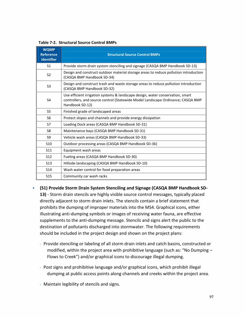
97
Table 7-2. Structural Source Control BMPs
WQMP Reference Identifier
Structural Source Control BMPs
S1 Provide storm drain system stenciling and signage (CASQA BMP Handbook SD-13)
S2 Design and construct outdoor material storage areas to reduce pollution introduction (CASQA BMP Handbook SD-34)
S3 Design and construct trash and waste storage areas to reduce pollution introduction (CASQA BMP Handbook SD-32)
S4 Use efficient irrigation systems & landscape design, water conservation, smart controllers, and source control (Statewide Model Landscape Ordinance; CASQA BMP Handbook SD-12)
S5 Finished grade of landscaped areas
S6 Protect slopes and channels and provide energy dissipation
S7 Loading Dock areas (CASQA BMP Handbook SD-31)
S8 Maintenance bays (CASQA BMP Handbook SD-31)
S9 Vehicle wash areas (CASQA BMP Handbook SD-33)
S10 Outdoor processing areas (CASQA BMP Handbook SD-36)
S11 Equipment wash areas
S12 Fueling areas (CASQA BMP Handbook SD-30)
S13 Hillside landscaping (CASQA BMP Handbook SD-10)
S14 Wash water control for food preparation areas
S15 Community car wash racks
(S1) Provide Storm Drain System Stenciling and Signage (CASQA BMP Handbook SD-
13) - Storm drain stencils are highly visible source control messages, typically placed
directly adjacent to storm drain inlets. The stencils contain a brief statement that
prohibits the dumping of improper materials into the MS4. Graphical icons, either
illustrating anti-dumping symbols or images of receiving water fauna, are effective
supplements to the anti-dumping message. Stencils and signs alert the public to the
destination of pollutants discharged into stormwater. The following requirements
should be included in the project design and shown on the project plans:
Provide stenciling or labeling of all storm drain inlets and catch basins, constructed or
modified, within the project area with prohibitive language (such as: “No Dumping –
Flows to Creek”) and/or graphical icons to discourage illegal dumping.
Post signs and prohibitive language and/or graphical icons, which prohibit illegal
dumping at public access points along channels and creeks within the project area.
Maintain legibility of stencils and signs.

98
See CASQA Stormwater Handbook BMP Fact Sheet SD-13 for additional information.
(S2) Design Outdoor Hazardous Material Storage Areas to Reduce Pollutant
Introduction (SD-34) - Improper storage of materials outdoors may increase the
potential for toxic compounds, oil and grease, fuels, solvents, coolants, wastes, heavy
metals, nutrients, suspended solids, and other pollutants to enter the MS4. Where the
plan of development includes outdoor areas for storage of hazardous materials that
may contribute pollutants to the MS4, the following stormwater BMPs are required:
Hazardous materials with the potential to contaminate urban runoff shall either be:
(a) placed in an enclosure such as, but not limited to, a cabinet, shed, or similar
structure that prevents contact with runoff or spillage to the MS4; or (b) protected
by secondary containment structures (not double wall containers) such as berms,
dikes, or curbs.
The storage area shall be paved and sufficiently impervious to contain leaks and spills.
The storage area shall have a roof or awning to minimize direct precipitation and
exposure, and collection of stormwater within the secondary containment area.
Any stormwater retained within the containment structure must not be discharged to
the street or storm drain system.
Location(s) of installations of where these preventative measures will be employed
must be included on the map or plans identifying BMPs.
See CASQA Stormwater Handbook Section 3.2.6 and BMP Fact Sheet SD-34 for
additional information.
(S3) Trash Enclosures to Reduce Pollutant (CASQA BMP Handbook SD-32) - Design
trash storage areas to reduce pollutant introduction. All trash container areas shall meet
the following requirements (limited exclusion: detached residential homes):
Paved with an impervious surface, designed not to allow run-on from adjoining areas,
designed to divert drainage from adjoining roofs and pavements diverted around
the area, screened or walled to prevent off-site transport of trash; and
Provide solid roof or awning to prevent exposure to direct precipitation.
Connection of trash area drains to the MS4 is prohibited. See CASQA Stormwater
Handbook Section 3.2.9 and BMP Fact Sheet SD-32 for additional information.
(S4) Use Efficient Irrigation Systems and Landscape Design (CASQA BMP Handbook SD-
12) The Water Conservation in Landscaping Act of 2006, Assembly Bill 1881 (AB 1881),

99
requires adoption of the Model Water Efficient Landscape Ordinance designed to
improve public and private landscaping and irrigation practices for new development
projects or rehabilitation of significant landscape areas. The ordinance reduces outdoor
water waste through improvements in irrigation efficiency and selection of plants
requiring less water. The ordinance requires development of water budgets for
landscaping, use of recycled water if available, routine irrigation audits, and scheduling
of irrigation based on localized climate. For existing landscapes greater than one-acre in
size, the water purveyors are required to implement programs, such as irrigation water
use analyses, irrigation surveys, and irrigation audits to reduce landscape water use to a
level not exceeding the Maximum Applied Water Allowance (MAWA) as specified in the
ordinance. Landscape audits are required to be conducted by a certified landscape
auditor. Irrigation practices shall also comply with any more stringent local ordinances
related to irrigation efficiency. The project proponent should also consult the LIP for the
area in which the project is planned for development. In general, the following methods
to reduce excessive irrigation runoff shall be considered, and incorporated for all
landscaped areas:
Employing rain shutoff devices to prevent irrigation after precipitation.
Designing irrigation systems to each landscape area’s specific water requirements.
Using flow reducers or shutoff valves triggered by a pressure drop to control water
loss in the event of broken sprinkler heads or lines.
The timing and application methods of irrigation water shall be designed to minimize
the runoff of excess irrigation water into the municipal storm drain system.
Employing other comparable, equally effective, methods to reduce irrigation water
runoff.
Group plants with similar water requirements in order to reduce excess irrigation
runoff and promote surface filtration. Choose plants with low irrigation
requirements (for example, native or drought tolerant species). Consider other
design features, such as:
Use mulches (such as wood chips or shredded wood products) in planter areas without ground cover to minimize sediment in runoff.
Install appropriate plant materials for the location, in accordance with amount of sunlight and climate, and use native plant material where possible and/or as recommended by the landscape architect.
Leave a vegetative barrier along the property boundary and interior watercourses, to act as a pollutant filter, where appropriate and feasible.

100
Choose plants that minimize or eliminate the use of fertilizer or pesticides to sustain growth.
(S5) Finished Grade of Landscaped Areas - All landscape pockets, fingers, setback areas,
parkway strips, street medians, etc., shall be finish-graded at a minimum of 1-2 inches
below top of curb or sidewalk for increased retention/infiltration of stormwater and
irrigation water.
(S6) Protect Slopes and Channels - Project plans should include Source Control BMPs to
decrease the potential for erosion of slopes and/or channels. The following design
principles should be considered and incorporated and implemented where determined
applicable and feasible by the local jurisdiction:
Convey runoff safely from the tops of slopes.
Avoid disturbing steep or unstable slopes.
Avoid disturbing natural channels.
Install permanent stabilization BMPs on disturbed slopes as quickly as possible.
Vegetate slopes with native or drought tolerant vegetation.
Control and treat flows in landscaping and/or other controls prior to reaching existing
natural drainage systems.
Install permanent stabilization BMPs in channel crossings as quickly as possible, and
ensure that increases in runoff velocity and frequency caused by the project do not
erode the channel.
Install energy dissipaters, such as riprap, at the outlets of new storm drains, culverts,
conduits, or channels that enter unlined channels in accordance with applicable
specifications to minimize erosion. Energy dissipaters should be installed in such a
way as to minimize impacts to receiving waters.
On-site conveyance channels should be lined, where appropriate, to reduce erosion
caused by increased flow velocity due to increases in tributary impervious area. The
first choice for linings should be grass or some other vegetative surface, since these
materials not only reduce runoff velocities, but also provide water quality benefits
from filtration and infiltration. Irrigation demand of vegetated systems should be
considered. If velocities in the channel are large enough to erode grass or other
vegetative linings, rock, riprap, concrete soil cement or geo-grid stabilization may be
substituted or used in combination with grass or other vegetation stabilization.

101
Other design principles which are comparable and equally effective.
These practices should be implemented, as feasible, consistent with local codes and
ordinances. Projects involving an alteration to bed, bank, or channel of a Water of
the US may require approval of additional regulatory agencies with jurisdiction over
water bodies, (e.g., the U.S. Army Corps of Engineers, the California Regional Water
Quality Control Boards and the California Department of Fish and Game).
(S7) Loading Dock Areas (CASQA BMP Handbook SD-31) - Loading /unloading dock
areas shall include the following:
Cover loading dock areas, or design drainage to preclude run-on and runoff, unless the
material loaded and unloaded at the docks does not have potential to contribute to
stormwater pollution, and this use is ensured for the life of the facility.
Direct connections to the municipal storm drain system from below grade loading
docks (truck wells) or similar structures are prohibited. Stormwater can be
discharged through a permitted connection to the storm drain system with a
treatment control BMP applicable to the use.
Other comparable and equally effective features that prevent unpermitted discharges
to the MS4.
Housekeeping of loading docks shall be consistent with Housekeeping of Loading Dock
Areas (SD-31).
See CASQA BMP Handbook Section 3.2.8 for additional information.
(S8) Maintenance Bays (CASQA BMP Handbook SD-31) - Maintenance bays shall
include the following:
Repair/maintenance bays shall be indoors; or, designed to preclude urban run-on and
runoff.
Design a repair/maintenance bay drainage system to capture all wash water, leaks and
spills. Provide impermeable berms, drop inlets, trench catch basins, or overflow
containment structures around repair bays to prevent spilled materials and wash-
down waters from entering the storm drain system. Connect drains to a sump for
collection and disposal. Direct connection of the repair/maintenance bays to the
MS4 is prohibited. If there are no other alternatives, discharge of non-stormwater
flow to the sanitary sewer may be considered only if allowed by the local sewerage
agency through permitted connection.

102
Other features which are comparable and equally effective that prevent discharges to
the MS4 without appropriate permits.
See CASQA BMP Handbook Fact Sheet SD-31 for additional information.
(S9) Vehicle Wash Areas (CASQA BMP Handbook SD-33) - Projects that include areas
for washing /steam cleaning of vehicles shall use the following:
Self-contained or covered with a roof or overhang.
Equipped with a wash rack, and with the prior approval of the sewerage agency (Note:
Discharge monitoring may be required by the sewerage agency).
Equipped with a clarifier or other pretreatment facility.
If there are no other alternatives, discharge of non-stormwater flow to the sanitary
sewer may be considered only allowed by the local sewerage agency through
permitted connection.
Other features which are comparable and equally effective that prevent unpermitted
discharge, to the MS4.
See CASQA BMP Handbook Sections 3.2.7 and 3.2.10 and Fact Sheet SD-33 for
additional information.
(S10) Outdoor Processing Areas (CASQA BMP Handbook SD-36) - Outdoor process
equipment operations, such as rock grinding or crushing, painting or coating, grinding or
sanding, degreasing or parts cleaning, landfills, waste piles, and wastewater and solid
waste handling, treatment, and disposal, and other operations determined to be a
potential threat to water quality by the local jurisdiction shall adhere to the following
requirements.
Cover or enclose areas that would be the sources of pollutants; or, slope the area
toward a sump that will provide infiltration or evaporation with no discharge; or, if
there are no other alternatives, discharge of non-stormwater flow to the sanitary
sewer may be considered only allowed by the local sewerage agency through
permitted connection.
Grade or berm area to prevent run-on from surrounding areas.
Installation of storm drains in areas of equipment repair is prohibited.
Other features which are comparable or equally effective that prevent unpermitted
discharges to the MS4.

103
Where wet material processing occurs (e.g. electroplating), secondary containment
structures (not double wall containers) shall be provided to hold spills resulting from
accidents, leaking tanks or equipment, or any other unplanned releases .
Some of these land uses (e.g. landfills, waste piles, wastewater and solid waste
handling, treatment and disposal) may be subject to other permits including Phase I
Industrial Permits that may require additional BMPs.
See CASQA Stormwater Handbook Section 3.2.5 for additional information.
(S11) Equipment Wash Areas - Outdoor equipment/accessory washing and steam
cleaning activities shall use the following:
Be self-contained or covered with a roof or overhang.
Design an equipment wash area drainage system to capture all wash water. Provide
impermeable berms, drop inlets, trench catch basins, or overflow containment
structures around equipment wash areas to prevent wash -down waters from
entering the storm drain system. Connect drains to a sump for collection and
disposal. Discharge from equipment wash areas to the MS4 is prohibited. If there
are no other alternatives, discharge of non-stormwater flow to the sanitary sewer
may be considered, but only when allowed by the local sewerage agency through a
permitted connection.
Other comparable or equally effective features that prevent unpermitted discharges
to the MS4.
(S12) Fueling Areas (CASQA BMP Handbook SD-30) - Fuel dispensing areas shall contain
the following:
At a minimum, the fuel dispensing area must extend 6.5 feet (2.0 meters) from the
corner of each fuel dispenser, or the length at which the hose and nozzle assembly
may be operated plus 1 foot (0.3 meter), whichever is less.
The fuel dispensing area shall be paved with Portland cement concrete (or equivalent
smooth impervious surface). The use of asphalt concrete shall be prohibited.
The fuel dispensing area shall have an appropriate slope (2 percent - 4 percent) to
prevent ponding, and must be separated from the rest of the site by a grade break
that prevents run-on of stormwater.
An overhanging roof structure or canopy shall be provided. The cover’s minimum
dimensions must be equal to or greater than the area of the fuel dispensing area in
the first item above. The cover must not drain onto the fuel dispensing area and the

104
downspouts must be routed to prevent drainage across the fueling area. The fueling
area shall drain to the project’s Treatment Control BMP(s) prior to discharging to the
MS4.
See CASQA Stormwater Handbook Section 3.2.11 and BMP Fact Sheet SD-30 for
additional information.
(S13) Site Design and Landscape Planning (Hillside Landscaping), (CASQA BMP
Handbook SD-10) - Hillside areas that are disturbed by project development shall be
landscaped with deep-rooted, drought tolerant plant species selected for erosion
control, satisfactory to the local jurisdiction.
(S14) Wash Water Controls for Food Preparation Areas - Food establishments (per
State Health & Safety Code 27520) shall have either contained areas or sinks, each with
sanitary sewer connections for disposal of wash waters containing kitchen and food
wastes. If located outside, the contained areas or sinks shall also be structurally covered
to prevent entry of stormwater. Adequate signs shall be provided and appropriately
placed stating the prohibition of discharging washwater to the storm drain system.
(S15) Community Car Wash Racks - In complexes larger than 100 dwelling units where
car washing is allowed, a designated car wash area that does not drain to a storm drain
system shall be provided for common usage. Wash waters from this area may be
directed to the sanitary sewer (with the prior approval of the sewerage agency); to an
engineered infiltration system; or to an equally effective alternative. Pre-treatment may
also be required.
7.4 Selecting Source Control BMPs
Identifying appropriate source control BMPs for a project is critical to reducing the potential
for sources of pollutants from contacting stormwater runoff. When completing WQMP
Template Form 4.1-1 (Non-Structural Source Control BMPs) and Form 4.1-2 (Structural Source
Control BMPs), reference Table 7-3 to complete the WQMP Template form. Table 7-3
presents a worksheet for identifying appropriate non-structural and structural source control
BMPs, based on project-specific potential sources of pollutants.
Note: Table 7-3 is intended as an example worksheet of how to consider selection of source
control BMPs based on project-specific characteristics and does not include all possible
project characteristics/activities and corresponding applicable source control BMPs.

105
Table 7-3. Source Control BMP Selection Worksheet If Potential Source of Runoff
Pollutants will be on the Project Site…
…then WQMP shall include these Source Control BMPs
Project Characteristic/Activity Non-structural BMPs Structural BMPs
Onsite Storm Drain Inlets N1 – Education for POA, Tenants, Occupants N2 – Activity Restrictions N4 – BMP Maintenance N12 – Employee Training N14 – Catch Basin Inspection
S1 - Provide Storm Drain Stenciling and Signage
Landscape/ Outdoor Pesticide Use
N1 – Education for POA, Tenants, Occupants N2 – Activity Restrictions N3 – Landscape Management; N4 – BMP Maintenance N12 – Employee Training
S4 – Use Efficient Irrigation Systems and Landscape Design; S5 - BMP S6 – Protect Slopes and Channels S13 – Site Design and Landscape Planning (Hillside Landscaping)
Food Service/Restaurants N4 – BMP Maintenance N12 – Employee Training
S3 - Design and construct trash and waste storage areas to reduce pollution introduction S14 – Wash Water Controls for Food Preparation Areas
Refuse Areas N1 – Education for POA, Tenants, Occupants N2 – Activity Restrictions N4 – BMP Maintenance N11 – Litter Control N12 – Employee Training
S3 - Design and construct trash and waste storage areas to reduce pollution introduction
Outdoor Storage of Equipment or Materials
N4 – BMP Maintenance N7 – Spill Contingency Plan N9 – Hazardous Materials Disclosure Compliance N12 – Employee Training
S2- Design Outdoor Materials Storage Areas S10 – Outdoor Processing Areas
Vehicle and Equipment Cleaning N1 – Education for POA, Tenants, Occupants N2 – Activity Restrictions N4 – BMP Maintenance N12 – Employee Training
S8 – Maintenance Bays & Docks S9 – Vehicle Wash Areas S11 – Equipment Wash Areas S15 – Community Wash Racks
Vehicle/Equipment Repair & Maintenance
N1 – Education for POA, Tenants, Occupants N2 – Activity Restrictions N4 – BMP Maintenance N12 – Employee Training
S8 – Maintenance Bays
Fuel Dispensing Areas N4 – BMP Maintenance N6 – Local Water Quality Permit Compliance N7 – Spill Contingency Plan ; N8 – Underground Storage Tank Compliance; N9 - Hazardous Materials Disclosure Compliance N12 – Employee Training
S12 – Fueling Areas
Loading Docks N4 – BMP Maintenance N13 – Housekeeping of Loading Docks; N12 – Employee Training
S7 – Dock Areas
Streets and Parking Lots N1 – Education for POA, Tenants, Occupants N2 – Activity Restrictions N4 – BMP Maintenance N12 – Employee Training; N15 – Street Sweeping Private Streets and Parking Lots
S1 - Provide Storm Drain Stenciling and Signage
Source: Adapted from San Diego Countywide Model SUSMP Manual, SUSMP Requirements for Development Applications, August 2010.

106
Section 8 – Post-Construction BMP Requirements This section includes post-construction requirements for operation and maintenance of BMPs
incorporated into an approved Project WQMP, and provides guidance for completing WQMP
Template, Form 5-1, BMP Inspection and Maintenance.
Scheduled operation and long term maintenance of BMPs is critical to the function and
effectiveness of BMPs. Other post-construction requirements include access agreements
between the property owner and local jurisdiction and recordation of the maintenance
agreements into the local deed records so that BMP maintenance requirements are disclosed
as part any property transfers.
8.1 BMP Maintenance Mechanisms
Alternative mechanisms that may be used to ensure on-going BMP maintenance include:
Public entity maintenance: The local jurisdiction with the responsibility for WQMP
approval may approve a WQMP that identifies a public or acceptable quasi-public entity
(e.g., the City, the County, County Flood Control District, an existing assessment district,
an existing utility district, or a conservation conservancy) as assuming responsibility for
operation, maintenance, repair and replacement of the BMP. Unless otherwise
acceptable to individual local agencies, public entity maintenance agreements shall
ensure estimated costs are front-funded or reliably guaranteed, (e.g., through a trust
fund, assessment district fees, bond, letter of credit or similar means). In addition, the
local jurisdictions may seek protection from liability by appropriate releases and
indemnities.
The project proponent must demonstrate that it has proposed transfer of the BMP
maintenance to another public entity. The project proponent will negotiate
maintenance requirements with the entity that it is proposing to accept maintenance
responsibilities within its jurisdiction; and negotiate with the resource agencies
responsible for issuing permits for the construction and/or maintenance of the facilities.
If necessary, the public entity will also demonstrate through the CEQA review or the
public entity’s public review process that it can accept the maintenance responsibility.
The local jurisdiction must be identified as a third party beneficiary empowered to
enforce any such maintenance agreement within their respective jurisdictions.
Project proponent agreement to maintain stormwater BMP: The local jurisdiction may
enter into a contract with the project proponent obligating the project proponent to
maintain, repair and replace the stormwater BMP as necessary into perpetuity. Security
or a funding mechanism with a “no sunset” clause may be required.

107
Assessment districts: The local jurisdiction may approve an assessment district or other
funding mechanism created by the project proponent to provide funds for stormwater
BMP maintenance, repair and replacement on an ongoing basis. Any agreement with an
assessment district shall be subject to the public entity maintenance provisions above.
Lease provisions: In those cases where the local jurisdiction holds title to the land in
question, and the land is being leased to another party for private or public use, the
local jurisdiction may assure stormwater BMP maintenance, repair and replacement
through conditions in the lease.
Conditional use permits: For discretionary projects only, the local jurisdiction may
assure maintenance of stormwater BMP through the inclusion of maintenance
conditions in the conditional use permit. Security may be required.
Alternative mechanisms: The local jurisdiction may accept alternative maintenance
mechanisms if such mechanisms are as protective as those listed above.
8.2 BMP Maintenance Requirements
The following sections describe general requirements that may be applicable to the
maintenance of BMPs. Consult the LIP for the jurisdiction in which the project is proposed to
determine specific local requirements.
8.2.1 Operation and Maintenance Plan
An Operation and Maintenance Plan (O&M Plan) for the BMPs shall be prepared and included
in the Project WQMP. The local jurisdiction requires the O&M Plan be received prior to
permit closeout (see Section 8.3) and the issuance of certificates of use and occupancy.
The O&M Plan describes the designated responsible party to manage the stormwater BMPs.
It also defines employee training program and duties, operating schedule, maintenance
frequency, routine service schedule, specific maintenance activities, copies of resource
agency permits, and any other necessary activities.
The final Project WQMP shall require the project proponent or approved maintenance entity
to complete and maintain O&M forms to document all maintenance requirements. Parties
responsible for the O&M Plan shall retain records for at least 5 years. These documents shall
be made available to the local jurisdiction for inspection upon request at any time.
8.2.2 O&M Commitments
At a minimum, the final Project WQMP shall require the inspection and servicing of all
structural BMPs on an annual basis. More frequent inspection and servicing requirements
may be required by the local jurisdiction.

108
As part of the maintenance mechanism selected above, the local jurisdiction shall require the
inclusion of a copy of an executed access easement that shall be binding on the land
throughout the life of the project, until such time that the stormwater BMPs requiring access
is replaced, satisfactory to the local agency.
8.2.3 Maintenance Agreements
Maintenance agreements are an effective tool for ensuring long-term maintenance of on-site
BMPs. The purpose of a maintenance agreement is to clearly define the responsibilities of
each party entering into the agreement. The local jurisdiction may require such an agreement
that could include the following:
Performance of routine maintenance: Local jurisdictions often find it easier to have a
property owner perform all maintenance according to the requirements of a Design
Manual. Other communities require that property owners do aesthetic maintenance
(i.e., mowing, vegetation removal) and implement pollution prevention plans, but elect
to perform structural maintenance and sediment removal themselves.
Maintenance schedules: Maintenance requirements may vary, but usually local
jurisdictions require that all BMP owners perform at least an annual inspection and
document the maintenance and repairs performed. An annual report must then be
submitted to the local jurisdiction, which may then choose to perform an inspection of
the facility.
Inspection requirements: Local jurisdictions may obligate themselves to perform an
annual inspection of a BMP, or may choose to inspect when deemed necessary instead.
Local agencies may also wish to include language allowing maintenance requirements to
be increased if deemed necessary to ensure proper functioning of the BMPs.
Access to BMPS: The agreement should grant permission to a local jurisdiction or its
authorized agent to enter onto property to inspect BMPS. If deficiencies are noted, the
local stormwater agency will provide a copy of the inspection report to the property
owner and provide a timeline for repair of the deficiencies.
Failure to maintain: In the maintenance agreement, the local jurisdiction will repeat
the steps available for addressing a failure to maintain situation. Language allowing
access to BMPS cited as not properly maintained may be included in the agreement,
along with the right to charge any costs for repairs back to the property owner. The
local jurisdiction may include deadlines for repayment of maintenance costs, and
provide for liens against property up to the cost of the maintenance plus interest.
Recording of the Maintenance Agreement: An important aspect to the recording of the
maintenance agreement is that the agreement be recorded into local deed records. This

109
recordation helps ensure that the maintenance agreement is bound to the property in
perpetuity.
Local jurisdictions may elect to include easement requirements in maintenance
agreements. While easement agreements are often secured through a separate legal
agreement, recording public access easements for maintenance in a maintenance
agreement reinforces a local jurisdiction’s right to enter and inspect a BMP. Examples of
maintenance agreements may be found at http://www.stormwatercenter.net/. Also,
consult the LIP to determine if the local jurisdiction has established a Maintenance
Agreement form.
8.3 Permit Closeout Requirements
For discretionary projects, the method approved by local jurisdictions for stormwater BMP
maintenance shall be incorporated into the project's permit, and shall be consistent with
permits issued by resource agencies, if any. Just as with all other aspects of a project’s
approved plans and designs, the local authority will make a determination whether all
requirements of the Project WQMP have been satisfactorily completed prior to close-out of
permits and issuance of certificates of use and occupancy.
For projects requiring only ministerial permits, the method approved by local jurisdictions for
stormwater BMP maintenance shall be shown on the project plans before the issuance of any
ministerial permits. Verification will occur similar to discretionary projects. Local jurisdictions
shall not issue construction approvals, permit closeout, and issuance of certificates of use and
occupancy prior to receipt of this proof.
In all instances, project proponents shall provide proof of execution of a method (as approved
by local jurisdiction) for maintenance, repair, and replacement of BMPs. For all properties,
the verification mechanism will include the project proponent's signed statement, as part of
the Project WQMP, accepting responsibility for all structural BMP maintenance, repair and
replacement or agreeing to an alternative mechanism that is approved by the local authority
regarding maintenance, repair and replacement of the structural BMPS.
Local authorities carrying out public projects that are not required to obtain permits shall be
responsible for ensuring that stormwater BMP maintenance; repair and replacement
requirements are identified prior to the completion of construction and incorporated into the
agency’s municipal activities program.

110
Section 9 -References American Society of Civil Engineers (ASCE). National Stormwater Best Management Practices (BMP)
Database, Version 1.0
ASCE and USEPA. August 2010. International Stormwater BMP Database, www.bmpdatabase.org.
California State Water Resources Control Board and Low Impact Development Center, 2009. Low
Impact Development Manual for Southern California: Technical Guidance and Site Planning
Strategies.
CASQA. 2003. California Stormwater BMP Handbooks. Three Handbooks: New Development and
Redevelopment, Municipal, and Industrial/Commercial are available at: www.cabmphandbooks.org
Center for Watershed Protection. Better Site Design: A Handbook for Changing Development Rules
in Your Community. 1998.
City of Los Angeles. April 2009. Green Infrastructure for Los Angeles: Addressing Urban Runoff and
Water Supply Through Low Impact Development.
County of San Diego. February 2010. San Diego Countywide Model Standard Urban Stormwater
Management Plan, SUSMP Requirements for Development Applications.
County of San Diego Department of Planning and Land Use. December 31, 2007. Low Impact
Development Handbook, Stormwater Management Strategies.
Gregory, J.H.; Dukes, M.D.; Jones, P.H.; and G.L. Miller. Effect of Urban Soil Compaction on
Infiltration Rate, Journal of Soil and Water Conservation, 2006, 1(3):117-124.
Orange County Stormwater Program. March 22, 2011. Final Draft Model Water Quality
Management Plan (WQMP).
Orange County Stormwater Program. March 22, 2011. Final Draft Technical Guidance Document
Appendices.
Orange County Stormwater Program, March 22, 2011. Final Draft Technical Guidance Document for
the Preparation of Conceptual/Preliminary and/or Project WQMPs.
Riverside County Flood Control and Watershed Conservation District. 2011. Draft Riverside County
LID BMP Manual.
Schueler, Thomas R. and Holland, Heather K. Center for Watershed Protection. 2000. The Practice
of Watershed Protection.

111
Urban Runoff Quality Management, American Society of Civil Engineers (ASCE) Manual and
Report on Engineering Practice No. 87/Water Environment Federation (WEF) Manual of Practice
No.23, 1998.
Urban Water Resources Research Council of ASCE Wright Water Engineers. National Stormwater
Best Management Practices Database, 2001.

![Technical Guidance Overview - New Jersey · Technical Guidance Overview George Nicholas Chairperson - DEP Technical Guidance Development ... [UST/LF] Presumptive Remedies Monitored](https://img.dokumen.tips/doc/110x75/5ebd185357241878db3b5ea8/technical-guidance-overview-new-jersey-technical-guidance-overview-george-nicholas.jpg)