Embed Size (px)
Citation preview

SCHAKO | Ferdinand Schad KG Phone +49 (0) 7463-980-0 Steigstraße 25-27 Fax +49 (0) 7463-980-200 D-78600 Kolbingen schako.com | [email protected]
Fig.: BAK-240
USABILITY CERTIFICATE
• General building supervisory approval (abZ) Z-41.3-574
CLASSIFICATION AND STANDARD
• Classification K30-U
• Test specifications - DIN 4102-2 - DIN 4102-6
PERFORMANCE DATA
• For installation into fire-resistant suspended ceilings (F30-A)
SPECIAL FEATURES
• The fire protection unit is fitted with two thermal trigger devices (72°C; located on the inside and outside). In case of fire, the triggering and the clo-sing motion of the shut-off damper happen inde-pendently of whether the temperature occurs first inside the ventilation ducts or outside.
• Fastening of the air diffuser to the suspended ceiling or fire protection unit with screw mounting (-SM).
BAK-240 Fire protection unit
Technical Documentation "Installation, Mounting and Operating Instructions"

Fire protection unit BAK-240 Technical documentation Table of Contents
Construction subject to change No return possible Version: 2019-12-01 | Page 2
TABLE OF CONTENTS Table of Contents .................................................... 2 Description .............................................................. 3 Models and dimensions .......................................... 5 Installation details .................................................. 6 Accessories ............................................................. 7 Order code .............................................................. 8 Specification texts ................................................. 10 Service .................................................................. 11 Foreign branch offices .......................................... 15 Indexes: Figures/tables ......................................... 16

Fire protection unit BAK-240 Technical documentation Description
Construction subject to change No return possible Version: 2019-12-01 | Page 3
DESCRIPTION Openings for ventilation ducts in fire-resistant suspended cei-lings must be sealed against fire and smoke by means of shut-off devices. The shut-off device type BAK-240 (hereafter refe-rred to as fire protection unit type BAK-240), of resistance class K30-U, according to general building approval (abZ) No. Z-41.3-574 is suitable for installation in fire-resistant suspen-ded ceilings. This ceiling must be designed as panelled ceiling in screw-type and spatulated design and must meet the re-quirements of an independent component of being fire-re-sistant for 30 minutes in the event of a fire from top or bot-tom. The use in supply or return air installations is possible. The fire protection unit is fitted with two thermal trigger de-vices (72°C), one located on the inside and one on the outs-ide. These trigger devices increase the safety of the fire pro-tection unit, as in case of fire, the triggering and closing mo-tion of the shut-off damper happen independently of whe-ther the temperature occurs first inside the ventilation ducts or outside. The fire protection unit type BAK-240 must not be connected to return air ducts in commercial kitchens or to extractor fans. Also the use of the fire protection unit in ventilation ducts is not permitted, if its function is prevented because of heavy soi-ling, extreme humidity or chemical contamination. For functional tests, service, retrofitting, etc., inspection ope-nings must be provided on site in suspended ceilings, shaft walls, connected ventilation ducts, etc., if necessary. They must be built-in in sufficient number and size and must not impair the functioning of the shut-off device.
VENTILATION FITTINGS
The fastening of the air diffusers is only possible via screw mounting (-SM). The following air diffusers can be fitted into the fire protection unit: Supply air: Return air: BDQJ-Q-SR-Z-… BDQJ-Q-SR-A-…
BDQJ-Q-SQ-Z-… BDQJ-Q-SQ-A-…
4DE-Z-… 4DE-A-… DQDL-Z-… DQDL-A-… 4DF-Z-… 4DF-A-… (For drawings, details, etc., see separate technical documenta-tion of corresponding air diffuser) Attention: The fittings in the fire protection unit increase the sound vo-lume of the air diffusers compared with the value in the dia-gram by +4 dB(a). Accessories - Description To increase protection, the fire protection unit type BAK-240 can have the following parts fitted, at an extra charge: Limit switch ES-1A (-ESA).

Fire protection unit BAK-240 Technical documentation Description
Construction subject to change No return possible Version: 2019-12-01 | Page 4
CONNECTION OF VENTILATION DUCTS
The fire protection unit type BAK-240 must only be connected to non-flammable ventilation ducts. The local regulations or national standards on ventilation systems (in Germany e.g. M-LüAR, in the locally applicable version) apply. No inadmis-sible forces may affect the fire protection unit and suspended ceiling especially in case of fire and impair their fire resistance time. The required expansion joints (flexible spigots) must be desig-ned as flammable, elastic spigots made of at least standard in-flammable materials (EN 13501-1) and installed between the fire protection unit and ventilation duct. Flexible part of the connection spigot (polyester fabric) must have a minimum length lmin of 100 mm when mounted. Flexible ventilation ducts made of steel or aluminium can be used instead of the flexible connection pieces. Ventilation ducts must be suspended separately. FUNCTIONAL TEST
Carry out a functional test of the fire protection unit before and after mounting it and ensure ready access. The function of all fire protection units must be tested every six months after commissioning the ventilation system. If two consecutive functional tests show no defects, the fire protection units only have to be tested once a year. If mainte-nance agreements are made for the ventilation systems, it is recommended to include the functional tests of the fire pro-tection unit in these agreements. The fire protection unit must be installed in a way that inner viewing, tests and cleaning are still possible. For these purposes, the air diffuser can be dismounted from the room side. If necessary, cleaning openings can be provi-ded for an additional cleaning of the shut-off damper area which is not accessible from the bottom side. If a limit switch etc. is fitted, an inspection opening in the suspended ceilings is necessary or accessibility in the intermediate ceiling area has to be ensured. Inspection openings in the suspended cei-lings should also be considered in order to allow the recurring inspections of safety systems which may become necessary. Note The proofs of usability, which are provided by us on request, are legally binding.
CONSTRUCTION
Fire protection unit housing - Galvanized sheet steel Shut-off damper - Metal-cased plasterboard (galvanised sheet steel) Air diffuser - Painted sheet steel in RAL 9010 (white) with blades Blades - Plastic, RAL colour 9010 (white) or RAL 9005 - Aluminium painted to the RAL colour of the faceplate - Sheet steel painted to RAL 9010 (white) ACCESSORIES
Limit switch ES-1A (-ESA) - electric, protection type IP67 AIR DIFFUSER FASTENING
Screw mounting (-SM) - Standard with 4 tapping screws with countersunk
head (on-site) Concealed mounting (-VM) - not possible!

Fire protection unit BAK-240 Technical documentation Models and dimensions
Construction subject to change No return possible Version: 2019-12-01 | Page 5
MODELS AND DIMENSIONS Dimensions
Figure 1: Dimensions BAK-240
1 Housing 2 Shut-off damper 3 Trigger device 4 Fusible link inside 5 Fusible link outside 6 Trigger clip 7 Catch spring 8 Limit switch (optional) 9 Protective cover 10 Shut-off steel sheet
Available sizes
Nominal size ØD 1) [mm]
□E [mm]
□F [mm]
□G [mm]
H [mm]
400 198* 382 390 472 386 500 248* 482 490 572 414
600/625 298* 582 590 672 443 * It is also possible to select a smaller spigot diameter øD 1) External dimensions
Table 1: Available sizes

Fire protection unit BAK-240 Technical documentation Installation details
Construction subject to change No return possible Version: 2019-12-01 | Page 6
Release device As standard, the fire protection unit is supplied with an inside and outside thermal trigger device (fusible link with 72°C trig-ger temperature)! Thus, in case of fire, the triggering and clo-sing motion of the shut-off damper happen independently of whether the temperature > 72°C occurs first on the inside or outside of the duct system. The breakage of one of the fusible links closes the shut-off damper and locks it into place. The fusible link must be replaced before the shut-off damper can be locked in the OPEN position again.
Figure 2: Trigger device (pos.3)
INSTALLATION DETAILS Installation
The fire protection unit type BAK-240 is fastened to the solid ceiling (F90) via four suspensions. Then the suspended ceiling (panelled ceiling in screw-type and spatulated design) is mounted. Afterwards, the air diffuser is connected to the sus-pended ceiling or the fire protection unit via screw mounting (-SM). The tension rod dimensions are calculated based on the loads of their own weight, of the connected ducts and of the air diffuser.
Weight Fire protection unit
Dimensioning of the tension rod
Nominal size
Weight [kg]
Dimen-sion
Allowed loads Fzul. (N)
per piece
400 20 500 28 M8 220
600/625 42 M10 348 Table 2: Weight of BAK-240 and tension rod dimensioning
Installation Instructions
Figure 3: Installation instructions
Detail Z
Figure 4: Detail Z
11 Intermediate ceiling area 12 Fire-resistant ceiling (on site) 13 Flexible spigot (on site) (class B“ according to DIN 4102) or flexible tube 14 Fire-resistant suspended ceiling 15 Screw mounting (SM) of air diffuser. For screw mounting, the swirl diffuser is fastened to the plenum box with 4 countersunk screws (on site). 16 Supply air 17 Return air 18 OPEN position 19 CLOSED position Detail A - Alternative ceiling fittings
Figure 5: Detail A
21 Washer to DIN EN ISO 7090 22 Hexagon nut to DIN EN ISO 4034 23 Tension rod (continuous) 24 Heavy duty wall plug
Fire protection unit BAK-240 Technical documentation Accessories
Construction subject to change No return possible Version: 2019-12-01 | Page 7
ACCESSORIES Available at an extra charge
Limit switch type ES-1A (-ESA)
Electric limit switch for position indication. Switching element including one NC and one NO contact each, 4 connections for M3,5 screw terminals for max. 2 mm². 250 V AC, Ie 6A, IP67 u-sing suitable cable glands M20 (on-site).
Figure 6: Circuit diagram of limit switch type ES-1A (-ESA) Ceiling diffusers
The BDQJ diffusers are models especially designed for fire protection units. Theses diffusers can only be used with the corresponding fire protection units. Their ventilation features are identical to those of the standard air diffusers DQJ-... (see separate technical documentation of ceiling swirl diffuser DQJ). Ceiling swirl diffuser BDQJ (-44)
Construction Faceplate
- Sheet steel (-SB) - Painted to RAL colour 9010 (white) (-9010) - Painted to a different RAL colour (-xxxx)
Blades - made of plastic
- Similar to RAL colour 9005 (black) (-L9005) - Similar to RAL colour 9006 (grey) (-L9006) - Similar to RAL colour 9010 (white) (-L9010)
- Made of aluminium - Painted to RAL colour 9010 (-A9010; standard) - Painted, RAL colour can be freely selected (-Axxxx)
(subsequent adjustment of blades not possible) - Without blades (-00000; only possible for return air)
Model BDQJ-Q-... - square faceplate
...-SR-... - with circular blade pattern
...-SQ-... - with square blade pattern
...-Z-...-PS-... - for supply air, with continuous blades
...-Z-500-...-PT-... - for supply air from NG500, possible with divided blades
...-A-...-P0-... - for return air, without blades
Nominal size - NG400 to 625
Drill pattern: ...-000-… - not reduced (standard) ...-310 to 500-… - reduced drill pattern
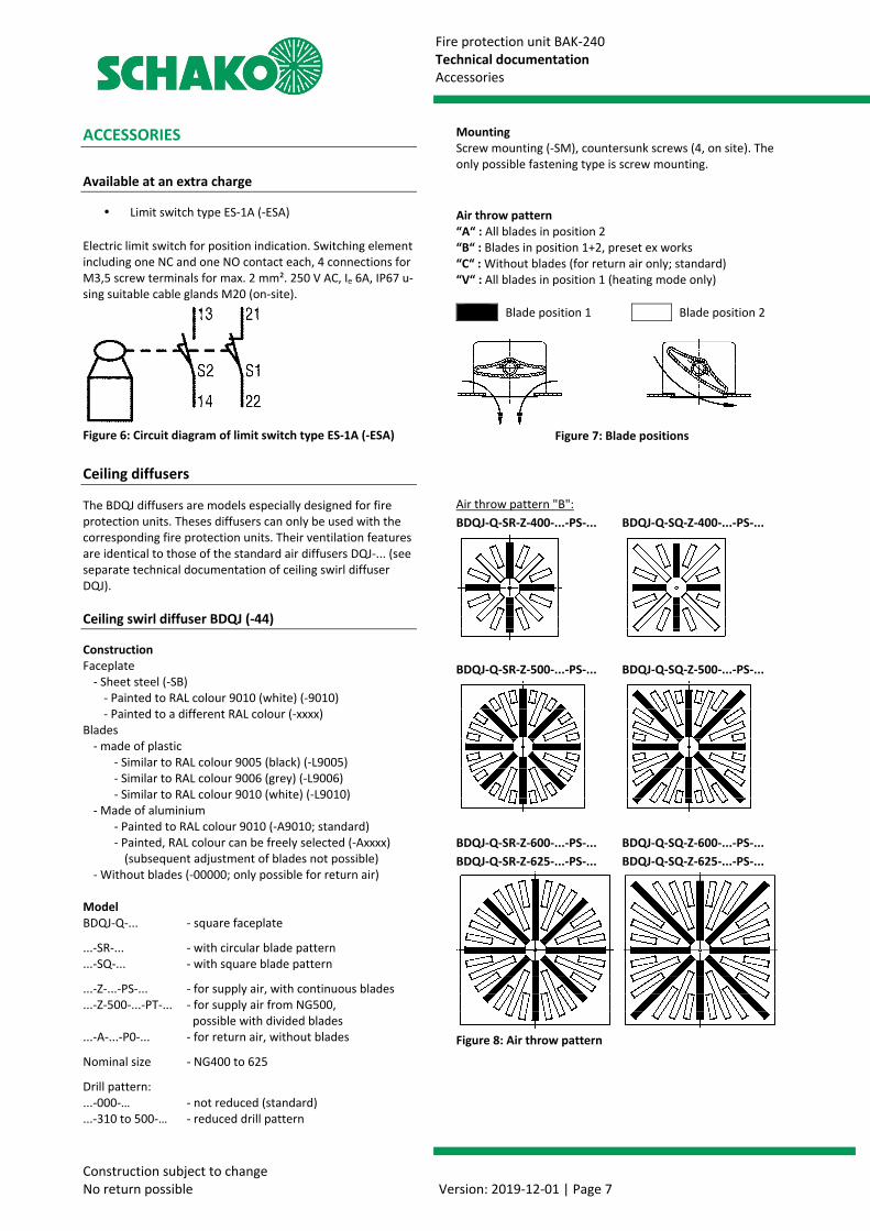
Mounting Screw mounting (-SM), countersunk screws (4, on site). The only possible fastening type is screw mounting.
Air throw pattern “A“ : All blades in position 2 “B“ : Blades in position 1+2, preset ex works “C“ : Without blades (for return air only; standard) “V“ : All blades in position 1 (heating mode only)
Blade position 1 Blade position 2
Figure 7: Blade positions
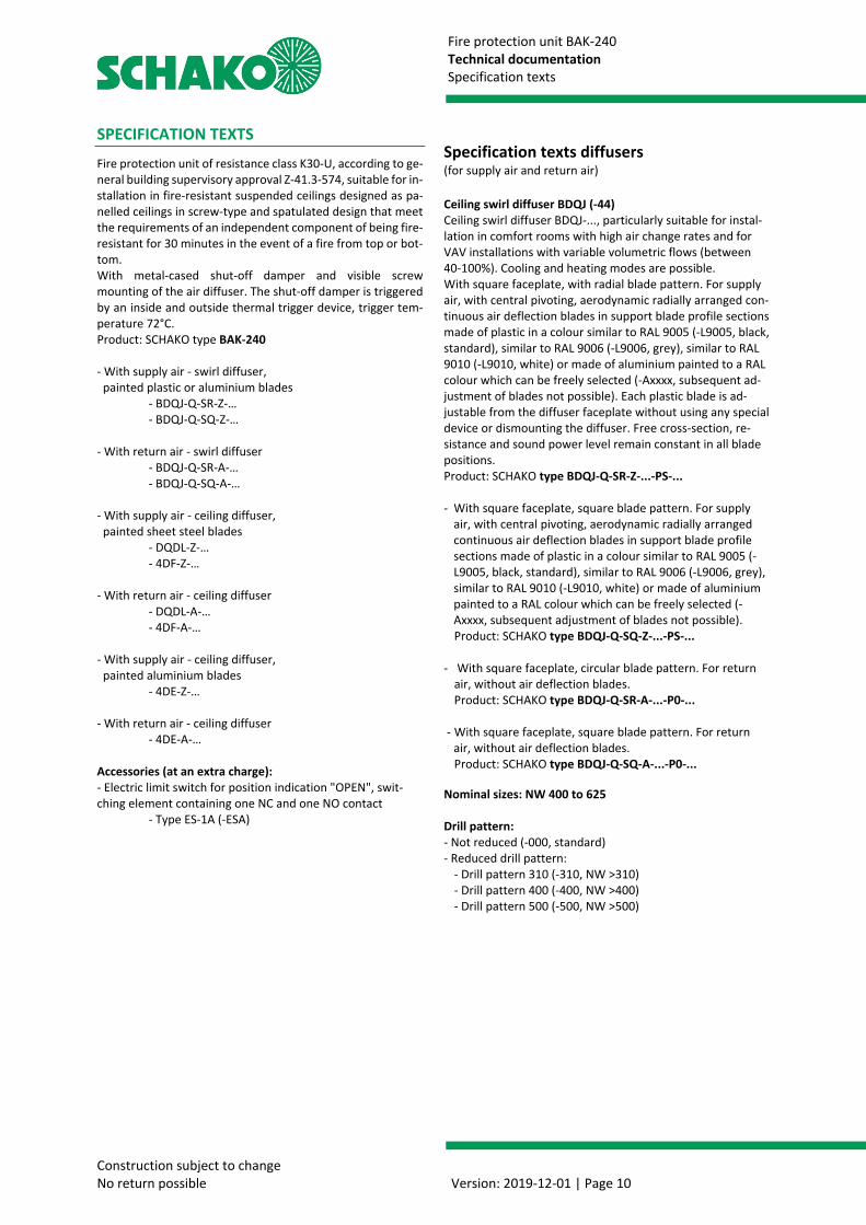
Air throw pattern "B": BDQJ-Q-SR-Z-400-...-PS-... BDQJ-Q-SQ-Z-400-...-PS-...
BDQJ-Q-SR-Z-500-...-PS-... BDQJ-Q-SQ-Z-500-...-PS-...
BDQJ-Q-SR-Z-600-...-PS-... BDQJ-Q-SQ-Z-600-...-PS-... BDQJ-Q-SR-Z-625-...-PS-... BDQJ-Q-SQ-Z-625-...-PS-...
Figure 8: Air throw pattern

Fire protection unit BAK-240 Technical documentation Order code
Construction subject to change No return possible Version: 2019-12-01 | Page 8
ORDER CODE BAK-240 ORDER CODE
01 02 03 04 05 06 07 Type Air diffuser Nominal size Spigot diameter Release temperature Type of drive Accessories
Example
BAK240 -44 -400 -158 -72 -HAN -ESA EXAMPLE BAK240-44-400-158-72-HAN-ESA Type BAK240 = fire protection unit BAK-240 | Air diffuser 44 = BDQJ | Nominal size = 400 mm | Spigot diameter = 158 mm | Trigger temperature 72 = 72°C | Actuator type HAN = thermo-mechanical triggering | Accessory ESA = ES-1A (limit switch in OPEN position) ORDER DETAILS 01 - TYPE
BAK240 = fire protection unit BAK-240 02 - AIR DIFFUSER (must be ordered separately)
06 = ceiling diffuser 4DE-… 07 = ceiling diffuser 4DF-… 17 = ceiling diffuser DQDL-… 44 = ceiling swirl diffuser BDQJ-… 03 - NOMINAL SIZE
400 - 500 - 600 - 625 in mm - always with three digits 04 - SPIGOT DIAMETER
098 - 123 - 138 - 158 - 178 - 198 - 222 - 248 - 298 in mm - always with three digits 05 - RELEASE TEMPERATURE
72 = 72°C 06 - ACTUATOR TYPE
HAN = thermo-mechanical triggering 07 - ACCESSORIES
Z00 = without accessories ESA = ES-1A (limit switch OPEN)

Fire protection unit BAK-240 Technical documentation Order code
Construction subject to change No return possible Version: 2019-12-01 | Page 9
BDQJ ORDER CODE
01 02 03 04 05 06 07
Type Model Blade pattern Air throw Nominal size Material Paint
Example
BDQJ -Q -SR -Z -500 -SB -9010
08 09 10 11 12 13 Drill pattern reduced Blades Blade colour Air throw pattern Mounting Cover
Example
-000 -PT -L9010 -A -SM -A0 EXAMPLE BDQJ-Q-SR-Z-500-SB-9010-000-PT-L9010-A-SM-A0 Type BDQJ = ceiling swirl diffuser for fire protection unit| Q = version with square faceplate | SR = circular blade pattern │ Z = air throw supply air | Nominal size = 500 mm | SB = faceplate made of sheet steel | 9010 = face plate painted to RAL9010 | Drill pattern 000 = not reduced | Blades PT = divided blades | Blade colour L9010 = plastic similar to RAL 9010 white | Air throw pattern A = all blades in position 2 | Mounting SM = screw mounting | Cover A0 = without cover ORDER DETAILS 01 - TYPE
BDQJ = ceiling swirl diffuser for fire protection unit 02 - MODEL
Q = square faceplate
03 - BLADE PATTERN
SR = circular SQ = square
04 - AIR THROW
Z = supply air A = return air
05 - NOMINAL SIZE
400 = NG 400 500 = NG 500 600 = NG 600 625 = NG 625
06 - MATERIAL
SB = sheet steel (standard, only available with paint)
07 - PAINT
9010 = RAL colour white (standard) xxxx = RAL colour can be freely selected (always with 4 digits)
08 - DRILL PATTERN REDUCED
000 = drill pattern not reduced (standard) 310 = reduced drill pattern 310, selected pattern must be smaller than nominal size 400 = reduced drill pattern 400, selected pattern must be smaller than nominal size 500 = reduced drill pattern 500, selected pattern must be smaller than nominal size
09 - BLADES
PT = divided blades (possible from NG500 – for supply air only) PS = continuous blades (only possible for supply air) P0 = without blades (only possible for return air)
10 - BLADE COLOUR
L9005 = blades similar to RAL 9005 (plastic, black) L9006 = blades similar to RAL 9006 (plastic, white aluminium) L9010 = blades similar to RAL9010 (plastic, white) A9010 = aluminium, RAL colour 9010 (standard) Axxxx = aluminium, RAL colour can be freely selected 00000 = without blades (only possible for return air))
11 - AIR THROW PATTERN
A = All blades in position 2 B = blades in position 1+2, preset ex works C = without blades (only possible for return air) V = all blades in position 1 (heating mode only)
12 - MOUNTING
SM = screw mounting (standard)
13 - COVER
A0 = without cover (standard) AD = With 1/4 cover (only possible for supply air model)
Fire protection unit BAK-240 Technical documentation Specification texts
Construction subject to change No return possible Version: 2019-12-01 | Page 10
SPECIFICATION TEXTS Fire protection unit of resistance class K30-U, according to ge-neral building supervisory approval Z-41.3-574, suitable for in-stallation in fire-resistant suspended ceilings designed as pa-nelled ceilings in screw-type and spatulated design that meet the requirements of an independent component of being fire-resistant for 30 minutes in the event of a fire from top or bot-tom. With metal-cased shut-off damper and visible screw mounting of the air diffuser. The shut-off damper is triggered by an inside and outside thermal trigger device, trigger tem-perature 72°C. Product: SCHAKO type BAK-240 - With supply air - swirl diffuser, painted plastic or aluminium blades - BDQJ-Q-SR-Z-… - BDQJ-Q-SQ-Z-… - With return air - swirl diffuser
- BDQJ-Q-SR-A-… - BDQJ-Q-SQ-A-… - With supply air - ceiling diffuser, painted sheet steel blades - DQDL-Z-… - 4DF-Z-… - With return air - ceiling diffuser - DQDL-A-… - 4DF-A-… - With supply air - ceiling diffuser, painted aluminium blades - 4DE-Z-… - With return air - ceiling diffuser - 4DE-A-… Accessories (at an extra charge): - Electric limit switch for position indication "OPEN", swit-ching element containing one NC and one NO contact - Type ES-1A (-ESA)
Specification texts diffusers (for supply air and return air) Ceiling swirl diffuser BDQJ (-44) Ceiling swirl diffuser BDQJ-..., particularly suitable for instal-lation in comfort rooms with high air change rates and for VAV installations with variable volumetric flows (between 40-100%). Cooling and heating modes are possible. With square faceplate, with radial blade pattern. For supply air, with central pivoting, aerodynamic radially arranged con-tinuous air deflection blades in support blade profile sections made of plastic in a colour similar to RAL 9005 (-L9005, black, standard), similar to RAL 9006 (-L9006, grey), similar to RAL 9010 (-L9010, white) or made of aluminium painted to a RAL colour which can be freely selected (-Axxxx, subsequent ad-justment of blades not possible). Each plastic blade is ad-justable from the diffuser faceplate without using any special device or dismounting the diffuser. Free cross-section, re-sistance and sound power level remain constant in all blade positions. Product: SCHAKO type BDQJ-Q-SR-Z-...-PS-... - With square faceplate, square blade pattern. For supply
air, with central pivoting, aerodynamic radially arranged continuous air deflection blades in support blade profile sections made of plastic in a colour similar to RAL 9005 (-L9005, black, standard), similar to RAL 9006 (-L9006, grey), similar to RAL 9010 (-L9010, white) or made of aluminium painted to a RAL colour which can be freely selected (-Axxxx, subsequent adjustment of blades not possible).
Product: SCHAKO type BDQJ-Q-SQ-Z-...-PS-... - With square faceplate, circular blade pattern. For return
air, without air deflection blades. Product: SCHAKO type BDQJ-Q-SR-A-...-P0-... - With square faceplate, square blade pattern. For return
air, without air deflection blades. Product: SCHAKO type BDQJ-Q-SQ-A-...-P0-... Nominal sizes: NW 400 to 625 Drill pattern: - Not reduced (-000, standard) - Reduced drill pattern: - Drill pattern 310 (-310, NW >310) - Drill pattern 400 (-400, NW >400) - Drill pattern 500 (-500, NW >500)

Fire protection unit BAK-240 Technical documentation Service
Construction subject to change No return possible Version: 2019-12-01 | Page 11
SERVICE Checking the function, cleaning, repair Polluted and damp air can impair the continuous operational safety. This is why, after commissioning the ventilation in-stallation, all shut-off devices must be subjected to a functio-nal test at a six-month interval, according to section 3.3 of the general building supervisory approval Z-41.3-574. If two consecutive functional tests show no defects, the shut-off devices only have to be tested at a yearly interval. If maintenance agreements are made for ventilation systems, it is recommended to include the functional tests of the shut-off devices in these agreements. The functional test of the shut-off device can be performed from the bottom side of the fire-resistant suspended ceiling. To do so, the air diffuser must be dismounted. If necessary, cleaning openings can be provided for an additional cleaning of the shut-off damper area which is not accessible from the bottom side. If a limit switch etc. is fitted, an inspection ope-ning in the suspended ceilings is necessary or accessibility in the intermediate ceiling area has to be ensured. Inspection o-penings in the suspended ceilings should also be considered in order to allow the recurring inspections of safety systems which may become necessary. There is a risk of injury during functional tests. Therefore, to avoid any cutting, crushing, impact or other possible injuries, personal protective equipment (PPE) must be worn. 1. Functional test Check all visible parts inside the housing. Carefully perform the required cleaning work, for example in order to avoid damage to the sealings. If defects have been detected during the func-tional test, they must be eliminated immediately. Defective parts may only be replaced with new original spare parts by the manufacturer. 1.1 Visual inspection • In order to reach the fire protection unit, the air diffuser
(pos.15) must be removed. The shut-off damper must be secured against accidental closing, otherwise there is a significant risk of injury.
• Check the fire protection unit for damage and contami-nation (e.g. housing, shut-off damper, seals).
• Performing necessary cleaning work 1.2 Shut-off damper housing • All hinges must be checked for tight seat. Loose screws
must be tightened and sluggishly running hinges must be lubricated with a resin- and acid-free lubricant.
1.3 Seal • Replace seals that have become loose or porous due to
ageing.
2 Thermo-mechanical trigger device 2.1 Dismounting the trigger device • Push up the shut-off damper (pos.2) and the shut-off
steel sheet (pos.10) and hang the trigger clip (pos.6) out. At the same time, the shut-off damper and the shut-off steel sheet must be supported manually or secured in another way to avoid spontaneous closing (attention if limit switches are fitted). While the shut-off damper is supported/secured, the shut-off steel sheet can be released and closed slowly toward the spigot. In doing so, the trigger device (pos.3) becomes visible above the spigot (pos.27). Loosen the 4 hexagon nuts M6 (pos.25). Tilt the trigger device (pos.3) with the two trigger units to the spigot (pos.27) and remove it from the housing.
• Now, you can put the shut-off damper in closing posi-tion. While closing, the locking clip (pos.26) overruns the catch spring (pos.7) and locks the shut-off damper in the closed position.
Figure 9: Sectional view of BAK-240
2 Shut-off damper 3 Trigger device 6 Trigger clip 7 Catch spring 10 Shut-off steel sheet 15 Screw mounting (SM) of air diffuser 25 Hexagon nuts (4 pc.) 26 Locking clip 27 connecting spigot

Fire protection unit BAK-240 Technical documentation Service
Construction subject to change No return possible Version: 2019-12-01 | Page 12
2.2 Checking and mounting the trigger device • Check the trigger device (pos.3) including the fusible
links (pos.4+5). Remove soiling which could impair the function. If, for example, the fusible links are damaged or corro-ded, they must be replaced. If there are no visible signs of damage or if the fusible links have already been replaced, perform the installa-tion of the trigger device in the reverse order (see sec-tion 2.1.). While opening the shut-off damper, make sure that the catch spring (pos.7) is pushed against the housing to release the lock.
Figure 10: Trigger device (pos.3)
4 Fusible link inside 5 Fusible link outside 28 Fastening bracket with nib 29 Trigger bolt 30 Support plate with nib 31 Compression spring

Fire protection unit BAK-240 Technical documentation Service
Construction subject to change No return possible Version: 2019-12-01 | Page 13
SAMPLE OF FUNCTIONAL TEST PROTOCOL
SCHAKO Ferdinand Schad KG Steigstrasse 25-27 D-78600 Kolbingen Phone: +49 (0)7463 / 980-0
Fax: +49 (0)7463 / 980-200 E-Mail: [email protected]
Web: schako.com
Sample Functional test protocol for____________________ Cons. No. ____________________ Usability certificate:
Series:
Release device:
The following functional steps have been carried out according to the documents installation, mounting and operating instructions
Prior to commissioning
Next functional test in: _____________
Next functional test in: _____________
Next functional test in: _____________
Next functional test in: _____________
External check:
System: _____________________ Item: _______________________ Internal check:
System: _____________________ Item: _______________________ Additional check:
System: _____________________ Item: _______________________
without defects Date / tester
with defects (see back) Date / tester
without defects Date / tester

Fire protection unit BAK-240 Technical documentation Service
Construction subject to change No return possible Version: 2019-12-01 | Page 14
SCHAKO Ferdinand Schad KG Steigstrasse 25-27 D-78600 Kolbingen Phone: +49 (0)7463 / 980-0 Fax: +49 (0)7463 / 980-200 E-mail: [email protected]
Web: schako.com
Sample Functional test protocol for____________________ Cons. No. ____________________ Defects found during the test on: ________________________________________ Sluggishness due to soiling.
Defects found during the test on: ________________________________________ Defects found during the test on: ________________________________________ Defects found during the test on: ________________________________________

Fire protection unit BAK-240 Technical documentation Foreign branch offices
Construction subject to change No return possible Version: 2019-12-01 | Page 15
FOREIGN BRANCH OFFICES
Belgium Denmark England France SCHAKO S.A.R.L. Venti AS SCHAKO Ltd. SCHAKO s.a.r.l. 165, rue des Pommiers Banevænget 3 Index House 16 Boulevard de la Croix Rousse L-2343 Luxembourg 8362 Hørning St Georges Lane, Ascot F-69001 Lyon Phone: +352 / 403 157 1 Phone: +45 / 86 92 22 66 SL5 7EU Berkshire Phone: +33 / 4 / 78 34 97 34Fax: +352 / 403 157 66 Fax: +45 / 86 92 22 26 Phone: +44 / 13 44 63 63 89 Fax: +33 / 4 / 78 34 97 31 [email protected] [email protected] Fax: +44 / 13 44 87 46 58 [email protected] schako.com www.venti.dk [email protected] schako.com schako.com Greece Israel Italy Croatia EUROPERSIS Insupco Industrial Supply Ltd. SCHAKO Italia S.r.l. Intel Trade Odisea Androutsou 2 40 Hayarkon St. Via XXV Aprile, 17 Dr. Ante Mandica 10 GR-56224 Evosmos/Tessaloniki Yavne 811 00 20097 S.Donato Milanese-MI HR-51410 Opatija Phone: +30 / 310 / 68 57 79 Phone: +972 / 8 / 94 20 080 Phone: +39 / 02 / 51 64 02 01 Phone: +385 / 51 741 100Fax: +30 / 310 / 75 76 13 Fax: +972 / 8 / 94 20 311 Fax: +39 / 02 / 51 62 09 46 Fax: +385 / 51 701 470 [email protected] [email protected] [email protected] [email protected] www.europersis.gr www.insupco.com schako.com www.intel-trade.hr Luxembourg Netherlands Austria Poland SCHAKO S.A.R.L. SCHAKO S.A.R.L. SCHAKO Vertriebs GmbH SCHAKO Polska Sp. z o.o 165, rue des Pommiers 165, rue des Pommiers Mariahilfer Straße 103/1/TOP 12 ul. Pulawska 38 L-2343 Luxembourg L-2343 Luxembourg A-1060 Wien PL-05-500 Piaseczno Phone: +352 / 403 157 1 Phone: +352 / 403 157 1 Phone: +43 / 1 / 890 24 62 Phone: +48 / 22 / 7263570 Fax: +352 / 403 157 66 Fax: +352 / 403 157 66 Fax: +43 / 1 / 890 24 62 50 Fax: +48 / 22 / [email protected] [email protected] [email protected] [email protected] schako.com schako.com schako.com schako.com Romania Sweden Switzerland Serbia & Montenegro SCHAKO Klima Luft SRL EXOTHERM AB SCHAKO Suisse SA TERMOMEHANIKA d.o.o.Str. Elena Caragiani nr.21 Box 60036 Rue Jean-Prouvé 28 Koste Glavinica 2 014212 Bucuresti, 21610 Limhamn 1762 Givisiez RS-11000 BEOGRAD Phone: +40 / 0 / 21 / 232 13 75 Phone: +46 / 40 / 631 61 16 Phone: +41 / 26 / 460 88 00 Phone: +381 / 11 / 369 99 93 Fax: +40 / 0 / 21 / 232 13 75 Fax: +46 / 40 / 15 60 95 Fax: +41 / 26 / 460 88 05 Fax: +381 / 11 / 369 09 [email protected] [email protected] [email protected] [email protected] schako.com www.exotherm.se schako.com www.termomehanika.rs Slovakia Spain Czech Republic Turkey SCHAKO SK s.r.o. SCHAKO IBERIA S.L. SCHAKO s.r.o. EMO-SCHAKO Klima Modrová 187 Departamento de Ventas Pred Skalkami II. 184/5 Havalandirma 91635 Modrová Pol. Ind. Río Gállego, CZ-10600 Praha 10-Zabehlice San. ve Tic. Ltd. Sti. Phone: +421 / 337 / 774 1843 Calle B, nave 3 Phone: +42 / 02 / 727 680 43 Pursaklar Sanayi Sitesi, Fax: +421 / 337 / 774 184 50840 San Mateo de Gállego /
Zaragoza Fax: +42 / 02 / 727 693 94 Karacaören Mah.1638.Cad.
No:98 [email protected] Phone: +34 / 976 / 531 999 [email protected] 06145 Altindag - Ankara schako.com Fax: +34 / 976 / 690 709 schako.com Phone: +90 / 312 527 16 05 [email protected] Fax: +90 / 312 527 16 08 schako.com [email protected] www.emo-schako.com.tr Hungary SCHAKO Kft. Tó Park 6 H-2045 Törökbálint Phone: +36 / 23 / 445670 Fax: +36 / 23 / 445679 [email protected] schako.com

Fire protection unit BAK-240 Technical documentation Indexes: Figures/tables
Construction subject to change No return possible Version: 2019-12-01 | Page 16
INDEXES: FIGURES/TABLES
List of figures
Figure 1: Dimensions BAK-240 ...................................... 5
Figure 2: Trigger device (pos.3) .................................... 6
Figure 3: Installation instructions ................................. 6
Figure 4: Detail Z ........................................................... 6
Figure 5: Detail A........................................................... 6
Figure 6: Circuit diagram of limit switch type ES-1A (-ESA) ............................................................................... 7
Figure 7: Blade positions ............................................... 7
Figure 8: Air throw pattern ........................................... 7
Figure 9: Sectional view of BAK-240 ........................... 11
Figure 10: Trigger device (pos.3) ................................ 12
List of tables
Table 1: Available sizes ................................................. 5
Table 2: Weight of BAK-240 and tension rod dimensioning ................................................................ 6