Embed Size (px)
Citation preview

MISSION PROVEN, CHALLENGE READY
TTEECCHHNNIICCAALL DDEESSCCRRIIPPTTIIOONN
MD Helicopters, Inc. Marketing and Sales 4555 E. McDowell Rd. Mesa, AZ 85215 480-346-6130 www.mdhelicopters.com [email protected]
MMDD 553300FF HHEELLIICCOOPPTTEERR

THIS PAGE INTENTIONALLY LEFT BLANK

MD Helicopters, Inc. 4555 E. McDowell Rd
Mesa, Arizona CAGE: 1KVX4
DUNS: 054313767 www.mdhelicopters.com
TECHNICAL DESCRIPTION
MD 530F HELICOPTER
This Technical Description includes information and intellectual property that is the property of MD Helicopters, Inc. (MDHI). It provides general information for evaluation of the design, equipment, and performance of the MD 530F helicopter. The information presented in this Technical Description does not constitute an offer and is subject to change without notice. This proprietary information, in its entirety, shall not be duplicated, used, or disclosed—directly or indirectly, in whole or in part—for any purpose other than for evaluation. MD Helicopters, Inc. reserves the right to revise this Technical Description at any time

MD 530F Technical Description
REPORT NO.: NO. OF PAGES:
MD14030710-530FTD 50
Use or disclosure of data in this Technical Description is subject to the restriction on the cover page of this document.
ATTACHMENTS:
None
Revision By Approved Date Pages and/or Paragraphs Affected New
07-Mar-14 All (Initial Issue)

MD 530F Technical Description
Report No. MD14030710-530FTD i 07 March 2014
USE OR DISCLOSURE OF DATA IN THIS TECHNICAL DESCRIPTION IS SUBJECT TO THE RESTRICTION ON THE COVER PAGE
MDHI PROPRIETARY
Contents 1. FOREWORD ........................................................................................................ 1
2. KEY ADVANTAGES AND FEATURES ............................................................... 3
3. CERTIFICATION .................................................................................................. 5
4. DIMENSIONS, WEIGHT, AND MISSION CONFIGURATION .............................. 7
4.1 EXTERNAL DIMENSIONS.............................................................................................. 7
4.2 INTERNAL DIMENSIONS ............................................................................................... 7
4.3 WEIGHT ..................................................................................................................... 9
4.4 CONFIGURATION ........................................................................................................ 9
5. MD 530F SINGLE-ENGINE HELICOPTER........................................................ 11
5.1 SYSTEM DESCRIPTION ............................................................................................. 11
5.2 STANDARD EQUIPMENT ............................................................................................ 13
5.3 MD 530F OPTIONAL EQUIPMENT .............................................................................. 14
5.4 FUSELAGE ............................................................................................................... 15
5.5 EXTERIOR ................................................................................................................ 17
5.6 EXTERNAL LIGHTING ................................................................................................ 17
5.7 INTERIOR ................................................................................................................. 18
5.7.1 Cockpit .................................................................................................................... 18
5.7.2 Cabin Compartment ................................................................................................ 18
5.7.3 Engine Compartment .............................................................................................. 18
5.8 SYSTEMS ................................................................................................................. 19
5.8.1 Fuel System ............................................................................................................ 19
5.8.2 Propulsion System .................................................................................................. 19
5.8.3 Drive System ........................................................................................................... 20
5.8.4 Rotor System ........................................................................................................... 20
5.8.5 Inlet Barrier Filter System ........................................................................................ 22
5.8.6 Flight Control System .............................................................................................. 22
5.8.7 Electrical System ..................................................................................................... 23
5.8.8 Environmental Control System ................................................................................ 23
5.8.9 Monitoring Instrumentation ...................................................................................... 24
5.8.10 Caution / Warning Annunciators ............................................................................. 24
5.8.11 Avionics / Communications ..................................................................................... 24
5.8.12 Next-Generation Electronic Flight Instrument System ............................................ 25

MD 530F Technical Description
Report No. MD14030710-530FTD 07 March 2014
USE OR DISCLOSURE OF DATA IN THIS TECHNICAL DESCRIPTION IS SUBJECT TO THE RESTRICTION ON THE COVER PAGE
MDHI PROPRIETARY
ii
6. PERFORMANCE SPECIFICATION ................................................................... 27
6.1 MD 530F – ROLLS-ROYCE MODEL 250-C30 TURBOSHAFT ENGINE ........................... 27
6.2 ENVIRONMENTAL IMPACT.......................................................................................... 28
6.3 SAFETY.................................................................................................................... 29
6.3.1 Crashworthiness ...................................................................................................... 29
6.4 HUMAN SYSTEMS INTERFACE ................................................................................... 31
7. MAINTENANCE AND SERVICING .................................................................... 33
7.1 MAINTENANCE ......................................................................................................... 33
7.2 SERVICING ............................................................................................................... 36
7.3 HOURLY COST ......................................................................................................... 38
8. PRODUCT SUPPORT ....................................................................................... 41
8.1 TRAINING ................................................................................................................. 41
8.1.1 Pilot Training ........................................................................................................... 41
8.1.2 Transition Flight Training ......................................................................................... 41
8.1.3 Recurrent Flight Training ......................................................................................... 41
8.1.4 Maintenance Training .............................................................................................. 42
8.2 WARRANTY .............................................................................................................. 42
8.2.1 Warranty Claims ...................................................................................................... 42
8.3 SERVICE CENTERS ................................................................................................... 43
8.4 FIELD SERVICE......................................................................................................... 43

MD 530F Technical Description
Report No. MD14030710-530FTD 07 March 2014
USE OR DISCLOSURE OF DATA IN THIS TECHNICAL DESCRIPTION IS SUBJECT TO THE RESTRICTION ON THE COVER PAGE
MDHI PROPRIETARY
1
1. FOREWORD This document presents basic technical description of the five-place MD Helicopters, Inc. (MDHI) MD 530F helicopter built in Mesa, Arizona, USA. It is designed to provide high-level technical information of the helicopter, advantages / features, and configurations. For more detailed information, an MD 530F Product Specification is available by contacting one of the Sales Team Members listed below. The MD 530F light turbine is a five-blade, five-passenger helicopter that uses a single Rolls-Royce 650 shaft horsepower (shp) turboshaft engine, is multi-mission capable, and is currently in use globally by commercial, government, and foreign military operators. The MD 530F has a relatively small diameter main rotor system and a short tail with a high horizontal stabilizer with two tip plates to provide vertical, longitudinal, and lateral stability in forward flight. Rotor blades can be folded to allow confined-enclosure storage. The MD 530F is certified for single pilot operation under visual flight rules / visual meteorological conditions.
MD Helicopter, Inc. Sales and Business Development
SALES BUSINESS DEVELOPMENT
Phone: 480.346.6474 Andy Pillado FAX: 480.346.6339 Director, Business Development E-Mail: [email protected] Phone: (480) 346.6532
Cell: (480) 435.3996 Fax: (480) 346.6818 E-Mail: [email protected]

MD 530F Technical Description
Report No. MD14030710-530FTD 07 March 2014
USE OR DISCLOSURE OF DATA IN THIS TECHNICAL DESCRIPTION IS SUBJECT TO THE RESTRICTION ON THE COVER PAGE
MDHI PROPRIETARY
2
THIS PAGE INTENTIONALLY LEFT BLANK

MD 530F Technical Description
Report No. MD14030710-530FTD 07 March 2014
USE OR DISCLOSURE OF DATA IN THIS TECHNICAL DESCRIPTION IS SUBJECT TO THE RESTRICTION ON THE COVER PAGE
MDHI PROPRIETARY
3
2. KEY ADVANTAGES AND FEATURES The MDHI MD 530F is a single turbine engine, rotary-wing aircraft. It has a cruising speed of 135 knots (249 kph / 155 mph), with a useful internal load at maximum gross weight is 1,519 pounds (689 kg). Hover out of ground effect is 6,800 feet (2,073 m) and hover in ground effect is 8,500 feet (2,591 m). The rate of climb at maximum gross weight is 1,770 feet (9.0 m/sec). The maximum operating altitude is 16,000 feet (4,877 m) with a -40 to +52C (-40 to 126F) operating temperature range.
The MD 530F Advantages / Features
Airframe
Simple system design Mature, field-proven systems and
components Separate cockpit and cabin 2+2 or 2+3 seating capability Speed, agility, and load-capable Certified to 14 CFR Part 27; VFR Approved / certified in over 50 countries
worldwide External power receptacle
Integrated landing gear dampers Fully articulated main rotor blades Main rotor system removal independent
from main rotor transmission Main rotor transmission removal
independent from main rotor system Proven record of high dependability High availability
Integrated Safety Features
Designed for operator ease Main rotor static mast / base designed to be
fail-safe to 100-percent design load Three-dimensional truss-type structure with
integral roll bar Energy-absorbing airframe with occupant
seat crush boxes for 20g shock resistance Extended, energy-attenuating landing gear Dual, crash-resistant elastomeric fuel cells
mounted between crash-resistant keel beams and bulkheads below the cabin floor
Empennage mounted tail skid Shoulder / seat belts attached to primary
structure Engine mounted low and at the rear Fuel filter automatic bypass if filter
becomes restricted Crew-seat four-point restraints Passenger seats provided with three-
point restraints Caution / warning annunciators / audible
warning tones
Supportability Features
Designed for ease of maintenance and supportability
Modular system design Designed for reparability Low direct operating costs
Maximum use of line replaceable units (Contd.):
o Empennage o Tail boom skid
Built-in Maintenance aids:

MD 530F Technical Description
Report No. MD14030710-530FTD 07 March 2014
USE OR DISCLOSURE OF DATA IN THIS TECHNICAL DESCRIPTION IS SUBJECT TO THE RESTRICTION ON THE COVER PAGE
MDHI PROPRIETARY
4
The MD 530F Advantages / Features
Maximum use of line replaceable units: o Engine o Avionics / communication o Flight controls o Main rotor blades o Main rotor drive shaft o Main rotor transmission o Main rotor transmission drive shaft o Main rotor mast o Tail rotor gearbox o Tail rotor blades o Landing gear o Canopies o Doors o Door handles o Door windows o Seat restraints o Tail boom o Oil-cooler / blower
o Engine fuel and oil filter impending bypass indicators
o Engine oil chip detector o Tail rotor transmission oil chip
detector o Main rotor transmission oil chip
detectors o Integrated engine compressor
wash system o Engine oil filler cap / dipstick o Main rotor transmission filler cap o Engine, main rotor transmission,
and tail rotor transmission oil level sight gage
o Footsteps located on each side for upper deck access without ground support equipment
o Landing gear ground handling wheel quick attach feature
Human Systems Integration Features Unobstructed forward 160-degree vertical
and 220-degree horizontal cockpit field of view
Cockpit designed to accommodate 25th to 95th percentile male / female flight crew
Integrated cockpit and cabin entry steps
Tail rotor drive shaft labeled for assembly ease / installation error-proofing
Integrated visual / audible warning indication for flight critical functions
Engine
Fuel efficient, field-proven, turboshaft engine
Externally accessible water wash system
Monitoring Instrumentation Caution / warning annunciator panel located
at the top of the instrument panel Digital upgrade pending

MD 530F Technical Description
Report No. MD14030710-530FTD 07 March 2014
USE OR DISCLOSURE OF DATA IN THIS TECHNICAL DESCRIPTION IS SUBJECT TO THE RESTRICTION ON THE COVER PAGE
MDHI PROPRIETARY
5
3. CERTIFICATION The MDHI MD 530F is a commercial Federal Aviation Administration (FAA) Type Certified aircraft under Code of Federal Regulations (CFR) Title 14, Part 27. The MD 530F was initially certified on July 1985. The MD 530F (369FF) is also a European Aerospace Safety Administration (EASA) Type Certified helicopter. Production, type, and supplemental type certificates are maintained by MDHI. A standard airworthiness certificate (FAA form 8100-2), displayed in the aircraft is the FAA official authorization allowing for the operation of type-certificated aircraft. The airworthiness certificate is displayed in the aircraft and remains valid as long as the aircraft meets the approved type design, is in a condition for safe operation, and maintenance, preventive maintenance, and alterations are performed in accordance with CFR Title 14, Part 21. The FAA designation is 369FF, and the International Civil Aviation Organization (ICAO) Type Designation is H500. MD Helicopters, Inc. commercial designation is MD 530F.

MD 530F Technical Description
Report No. MD14030710-530FTD 07 March 2014
USE OR DISCLOSURE OF DATA IN THIS TECHNICAL DESCRIPTION IS SUBJECT TO THE RESTRICTION ON THE COVER PAGE
MDHI PROPRIETARY
6
THIS PAGE INTENTIONALLY LEFT BLANK
MD 530F Technical Description
Report No. MD14030710-530FTD 07 March 2014
USE OR DISCLOSURE OF DATA IN THIS TECHNICAL DESCRIPTION IS SUBJECT TO THE RESTRICTION ON THE COVER PAGE
MDHI PROPRIETARY
7
4. DIMENSIONS, WEIGHT, AND MISSION CONFIGURATION
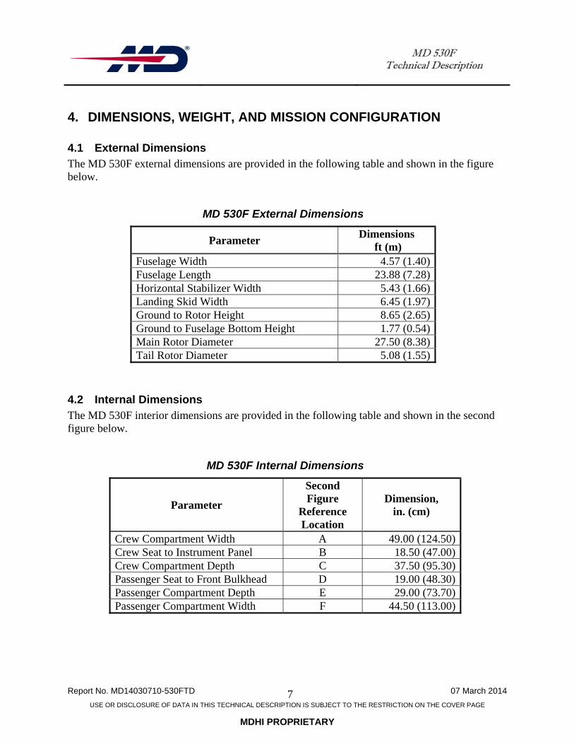
4.1 External Dimensions The MD 530F external dimensions are provided in the following table and shown in the figure below.
MD 530F External Dimensions
Parameter Dimensions
ft (m) Fuselage Width 4.57 (1.40) Fuselage Length 23.88 (7.28) Horizontal Stabilizer Width 5.43 (1.66) Landing Skid Width 6.45 (1.97) Ground to Rotor Height 8.65 (2.65) Ground to Fuselage Bottom Height 1.77 (0.54) Main Rotor Diameter 27.50 (8.38) Tail Rotor Diameter 5.08 (1.55)
4.2 Internal Dimensions The MD 530F interior dimensions are provided in the following table and shown in the second figure below.
MD 530F Internal Dimensions
Parameter
Second Figure
Reference Location
Dimension, in. (cm)
Crew Compartment Width A 49.00 (124.50) Crew Seat to Instrument Panel B 18.50 (47.00) Crew Compartment Depth C 37.50 (95.30) Passenger Seat to Front Bulkhead D 19.00 (48.30) Passenger Compartment Depth E 29.00 (73.70) Passenger Compartment Width F 44.50 (113.00)

MD 530F Technical Description
Report No. MD14030710-530FTD 07 March 2014
USE OR DISCLOSURE OF DATA IN THIS TECHNICAL DESCRIPTION IS SUBJECT TO THE RESTRICTION ON THE COVER PAGE
MDHI PROPRIETARY
8
MD 530F External Dimensions (Shown with Extended Landing Gear)

MD 530F Technical Description
Report No. MD14030710-530FTD 07 March 2014
USE OR DISCLOSURE OF DATA IN THIS TECHNICAL DESCRIPTION IS SUBJECT TO THE RESTRICTION ON THE COVER PAGE
MDHI PROPRIETARY
9
MD 530F Internal Dimension Locations
4.3 Weight Using the Rolls-Royce Model 250-C30 turboshaft engine, the MD 530F nominal weight is 1,591 pounds (722 kg).
4.4 Configuration Typical mission applications for the MD 530F are executive and personnel transport, air medical services, airborne law enforcement, and numerous other missions. It is also ideally suited for military requirements, both tactical and reconnaissance.

MD 530F Technical Description
Report No. MD14030710-530FTD 07 March 2014
USE OR DISCLOSURE OF DATA IN THIS TECHNICAL DESCRIPTION IS SUBJECT TO THE RESTRICTION ON THE COVER PAGE
MDHI PROPRIETARY
10
THIS PAGE INTENTIONALLY LEFT BLANK

MD 530F Technical Description
Report No. MD14030710-530FTD 07 March 2014
USE OR DISCLOSURE OF DATA IN THIS TECHNICAL DESCRIPTION IS SUBJECT TO THE RESTRICTION ON THE COVER PAGE
MDHI PROPRIETARY
11
5. MD 530F SINGLE-ENGINE HELICOPTER The MD 530F is a single-engine, rotary-wing aircraft originally certified as the Model 369FF. The MD 530F is certified for single-pilot operation under visual flight rules / visual meteorological conditions.
5.1 System Description The MD Helicopters, Inc. MD 530F is a five-place, single-engine, multipurpose helicopter. It has a fully-articulated five-blade main rotor system, and uses a two-blade tail rotor for anti-torque. An optional four-blade tail rotor is available for noise reduction. Power from the turboshaft engine is transmitted through the main drive shaft to the main rotor transmission, and from the main rotor transmission through a drive shaft to the tail rotor. A one-way clutch between the engine and main rotor transmission permits main-rotor freewheeling during auto-rotation. The rotor is supported by a hollow static mast mounted to the primary structure that absorbs all of the flight loads, allowing the transmission to provide only torque. The fuselage is teardrop-shaped, aerodynamically efficient, and is a semi-monocoque construction, manufactured primarily of aluminum alloy. The airframe includes doors for the pilot, copilot, and passenger area on both sides. Doors can be quickly removed and the helicopter flight-operated without the doors. The MD 530F, fixed-position, T-tail empennage consists of a horizontal stabilizer with tip plates mounted to the top of a vertical stabilizer. A tail skid is mounted to the bottom of the T-tail empennage. The empennage is mounted at the end of tail boom on the right-hand side, opposite the tail rotor gearbox, and is constructed of aluminum alloy. Its high altitude lift capability is achieved by main-rotor blades six inches longer than the MD 500E. The tail boom is extended and the tail rotor blades have been lengthened to provide increased thrust and directional control at high altitudes. A diagram of the major system components of the MD 530F is shown on the following page.

MD 530F Technical Description
Report No. MD14030710-530FTD 07 March 2014
USE OR DISCLOSURE OF DATA IN THIS TECHNICAL DESCRIPTION IS SUBJECT TO THE RESTRICTION ON THE COVER PAGE
MDHI PROPRIETARY
12
MD 530F Helicopter Major System Components
MD 530F Technical Description
Report No. MD14030710-530FTD 07 March 2014
USE OR DISCLOSURE OF DATA IN THIS TECHNICAL DESCRIPTION IS SUBJECT TO THE RESTRICTION ON THE COVER PAGE
MDHI PROPRIETARY
13
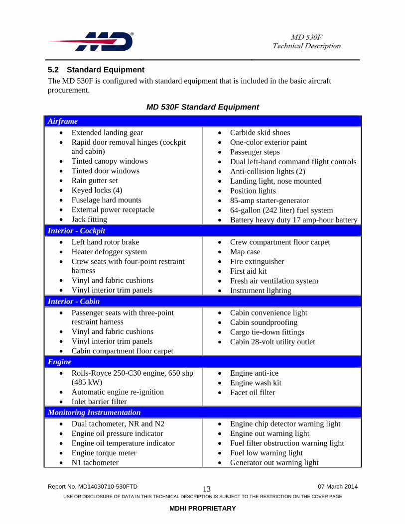
5.2 Standard Equipment The MD 530F is configured with standard equipment that is included in the basic aircraft procurement.
MD 530F Standard Equipment
Airframe
Extended landing gear Rapid door removal hinges (cockpit
and cabin) Tinted canopy windows Tinted door windows Rain gutter set Keyed locks (4) Fuselage hard mounts External power receptacle Jack fitting
Carbide skid shoes One-color exterior paint Passenger steps Dual left-hand command flight controls Anti-collision lights (2) Landing light, nose mounted Position lights 85-amp starter-generator 64-gallon (242 liter) fuel system Battery heavy duty 17 amp-hour battery
Interior - Cockpit
Left hand rotor brake Heater defogger system Crew seats with four-point restraint
harness Vinyl and fabric cushions Vinyl interior trim panels
Crew compartment floor carpet Map case Fire extinguisher First aid kit Fresh air ventilation system Instrument lighting
Interior - Cabin
Passenger seats with three-point restraint harness
Vinyl and fabric cushions Vinyl interior trim panels Cabin compartment floor carpet
Cabin convenience light Cabin soundproofing Cargo tie-down fittings Cabin 28-volt utility outlet
Engine
Rolls-Royce 250-C30 engine, 650 shp (485 kW)
Automatic engine re-ignition Inlet barrier filter
Engine anti-ice Engine wash kit Facet oil filter
Monitoring Instrumentation
Dual tachometer, NR and N2 Engine oil pressure indicator Engine oil temperature indicator Engine torque meter N1 tachometer
Engine chip detector warning light Engine out warning light Fuel filter obstruction warning light Fuel low warning light Generator out warning light

MD 530F Technical Description
Report No. MD14030710-530FTD 07 March 2014
USE OR DISCLOSURE OF DATA IN THIS TECHNICAL DESCRIPTION IS SUBJECT TO THE RESTRICTION ON THE COVER PAGE
MDHI PROPRIETARY
14
MD 530F Standard Equipment
Fuel quantity indicator Digital chronometer Airspeed indicator Barometric altimeter DC ammeter Outside air temperature indicator Magnetic compass Turbine outlet temperature indicator Battery over-temperature warning light
Low rotor rpm warning light Main transmission chip detector
warning light Main transmission oil pressure warning
light Main transmission oil temperature
warning light Tail rotor transmission chip detector
warning light
Miscellaneous
Engine, airframe, and battery log books Rotorcraft flight manual System/subsystem maintenance
manuals and illustrated parts catalogs Engine exhaust cover
Engine inlet cover Pitot tube cover Main rotor blade tie-downs Ground handling wheels Generator cooling kit
5.3 MD 530F Optional Equipment Optional equipment for the MD 530F is available for additional cost, and is literally non-exhaustive.
MD 530F Optional Equipment
Airframe
Heated pitot tube Paravion door openers Comfort windows Dual side mount Searchlights Moveable landing/searchlight Landing light pulse system Video turret side mount Pilot Mason Grip Engine bay quick release hinges Exterior crew handles Air conditioning R-134 w/ forward
evaporator Skid mirror
Two-/three-color standard exterior paint
Sealed lead-acid battery Cargo hook with hard mount Cargo hook provisions On-board cargo hook weighing system Emergency water floats High-visibility main rotor blades Night vision goggle compatible lighting Wire strike protection kit Twenty-one gallon auxiliary fuel tank Thirty-three gallon auxiliary fuel tank Tyler platform

MD 530F Technical Description
Report No. MD14030710-530FTD 07 March 2014
USE OR DISCLOSURE OF DATA IN THIS TECHNICAL DESCRIPTION IS SUBJECT TO THE RESTRICTION ON THE COVER PAGE
MDHI PROPRIETARY
15
MD 530F Optional Equipment
Interior – Cockpit
Leather covered interior panels Leather covered seats Black mesh seats 28-volt receptacle Pilot/copilot gooseneck lights
Right-hand command pilot Instrument panel face plate
modification Slant panel pedestal Night vision goggle compatible lighting
Interior - Cabin
Leather covered interior panels Leather covered seats
Black mesh seats 28-volt cabin and cockpit receptacles
Monitoring Instrumentation
Diamond J turbine outlet temperature indicator
Avionics cooling fan Blind encoder Encoding altimeter 3-inch Instantaneous vertical speed indicator Radar altimeter w/indicator Attitude gyro indicator, 3-inch Directional gyro - panel mounted Compass system (KCS55A) Radio magnetic indicator (K1229-00) Turn and bank indicator, 2-inch Turn and bank indicator, 3-inch
Various NAV / COM / GPS equipment Various transponders Various displays, radios, transceivers,
and data links Various audio panels, intercoms, CD player, AM / FM radios
Cyclic remote frequency switch Hand held radio provisions to include
AA-34 universal Communication headsets External PA /
siren system Forward looking infrared sensor Aero Computers mapping system
5.4 Fuselage The MD 530F fuselage is a teardrop-shaped, aerodynamically efficient structure that incorporates a high horizontal stabilizer. The fuselage is a semi-monocoque construction, manufactured primarily of aluminum alloy. It consists of a rigid, three-dimensional truss type structure, with an integral roll-bar design, for increased occupant safety. The airframe structure is designed to be energy absorbing and fails progressively in the event of impact. Occupant seat crush boxes are incorporated into the design and provide 20g shock resistance. The airframe includes doors for the pilot, copilot, and passenger area on both sides that can be quickly removed for flight. The fuselage structure, shown in the figure below, is divided into the following three main sections:

MD 530F Technical Description
Report No. MD14030710-530FTD 07 March 2014
USE OR DISCLOSURE OF DATA IN THIS TECHNICAL DESCRIPTION IS SUBJECT TO THE RESTRICTION ON THE COVER PAGE
MDHI PROPRIETARY
16
Forward section - comprised of a pilot compartment and, directly aft separated by a bulkhead, a passenger/cargo compartment. The pilot compartment is equipped with seats for the pilot and a copilot, or with copilot controls removed, one or two passengers. The passenger / cargo compartment, located in the center of the aircraft, contains provisions for installation of a bench or individual folding-type seats for two to three passengers. The lower fuselage structure beneath the pilot floor contains compartment space for the aircraft battery and provision for small cargo storage or installation of avionics equipment.
Aft section - includes the structure for the tail boom attachment and engine compartment. Lower section - divided by the center beam and provides the housing for the two fuel
cells. Provisions for the attachment of a cargo hook are located on the bottom of the fuselage in line with the center beam.
MD 530F Main Fuselage Assembly Sections

MD 530F Technical Description
Report No. MD14030710-530FTD 07 March 2014
USE OR DISCLOSURE OF DATA IN THIS TECHNICAL DESCRIPTION IS SUBJECT TO THE RESTRICTION ON THE COVER PAGE
MDHI PROPRIETARY
17
5.5 Exterior The MD 530F exterior can be painted a single color of the customer choice from available colors. An additional two, three, or more colors can be painted on the exterior for an additional cost. The exterior provides mounting locations for external antennas of customer-purchased avionics / communication equipment, external lighting, main rotor static mast, landing gear, and tail boom.
5.6 External Lighting The MD 530F external lighting (shown below) consists of a:
Rear position light assembly Rear anti-collision strobe light assembly Lower anti-collision strobe light assembly Left-hand red position light assembly Right-hand green position light assembly Landing hover light.
Standard cockpit lighting includes a cockpit light for the pilot. A passenger compartment convenience light is optional.
MD 530F Internal and External Lighting Locations

MD 530F Technical Description
Report No. MD14030710-530FTD 07 March 2014
USE OR DISCLOSURE OF DATA IN THIS TECHNICAL DESCRIPTION IS SUBJECT TO THE RESTRICTION ON THE COVER PAGE
MDHI PROPRIETARY
18
5.7 Interior The MD 530F interior consists of the cockpit area, cabin compartment area, and engine compartment. The MD 530F is provided with the utility interior.
5.7.1 Cockpit The cockpit has accommodations for the pilot and / or copilot. The minimum crew is one pilot in the command position. The instrument panel is located in the forward portion of the cockpit, and provides space for a full complement of avionics equipment. The instrument panel layout allows for easy scanning of flight instruments. The cockpit is ergonomically designed to facilitate single pilot operation in the left-hand or right-hand command configuration. All controls are within easy pilot reach. In addition, the anti-torque tail rotor control pedals are adjustable for up to 4 inches fore and aft to accommodate 25th-percentile to 95th-percentile male / female pilots. Seats are constructed of padded upholstered material and are attached to the forward bulkhead. Directly aft of the crew station, a bulkhead behind the forward compartment separates the cockpit and passenger / cargo compartment.
5.7.2 Cabin Compartment The passenger / cargo compartment provides space for passengers, cargo, or multi-mission equipment. The rear portion of the passenger / cargo compartment provides increased headroom and visibility. Standard seats are constructed of padded upholstered material and are attached to the rear bulkhead. Optional aluminum tube frame and black mesh seats are also available.
5.7.3 Engine Compartment The engine compartment is located aft and below the passenger compartment. The engine compartment provides an enclosed mounting platform for the turboshaft engine and can be easily accessed behind two clam-shell type doors contoured to the shape of the fuselage. The engine compartment can be easily accessed without ground support equipment or special equipment.

MD 530F Technical Description
Report No. MD14030710-530FTD 07 March 2014
USE OR DISCLOSURE OF DATA IN THIS TECHNICAL DESCRIPTION IS SUBJECT TO THE RESTRICTION ON THE COVER PAGE
MDHI PROPRIETARY
19
5.8 Systems
5.8.1 Fuel System The MD 530F fuel system consists of two interconnected bladder cells with a total capacity of 64 gallons (242.30 liter) located in bays below the passenger / cargo compartment floor of the lower section. Each bladder cell is internally supported by the airframe and contains electrically-powered fuel quantity transmitters that monitor fuel level and provide fuel quantity to the pilot. Low fuel level is displayed to the pilot through a yellow caution light on the instrument panel. Fuel flow from the bladder cells can be manually shutoff by the pilot using a mechanically actuated fuel shutoff valve control located on the instrument panel.
5.8.2 Propulsion System The engine used in the MD 530F is the Rolls-Royce Model 250-C30 gas turbine engine. The 250-C30 produces 650 shp, derated to 425 shp for takeoff, and 350 shp at maximum continuous operation. The engine consists of a combined four-stage axial and single-stage centrifugal compressor, a can-type combustion chamber, a four-stage turbine assembly, exhaust pipe, and accessory gearbox (AGB). The Model 250-C30 engine has an automatic re-ignition system that provides automatic activation (and pilot indication) of the ignition exciter activation in the event of an engine flameout and resulting engine power loss.
5.8.2.1 Engine Control Engine control is accomplished by fuel control actuation using the throttle twist grip located at the end of the collective stick. The throttle twist grip has three positions: cutoff, idle, and full open. Moving the throttle twist grip from cutoff to idle provides automatic fuel metering for engine starting, acceleration, and idle stabilization. Moving the throttle twist grip to full open during operation increases the gas producer speed and allows the power turbine governor speed control. The collective stick throttle twist grip movement friction is adjustable, and can also be locked when the operational gas producer turbine speed is attained.
Typical Rolls-Royce Model 250 Turboshaft Engine Cross Section

MD 530F Technical Description
Report No. MD14030710-530FTD 07 March 2014
USE OR DISCLOSURE OF DATA IN THIS TECHNICAL DESCRIPTION IS SUBJECT TO THE RESTRICTION ON THE COVER PAGE
MDHI PROPRIETARY
20
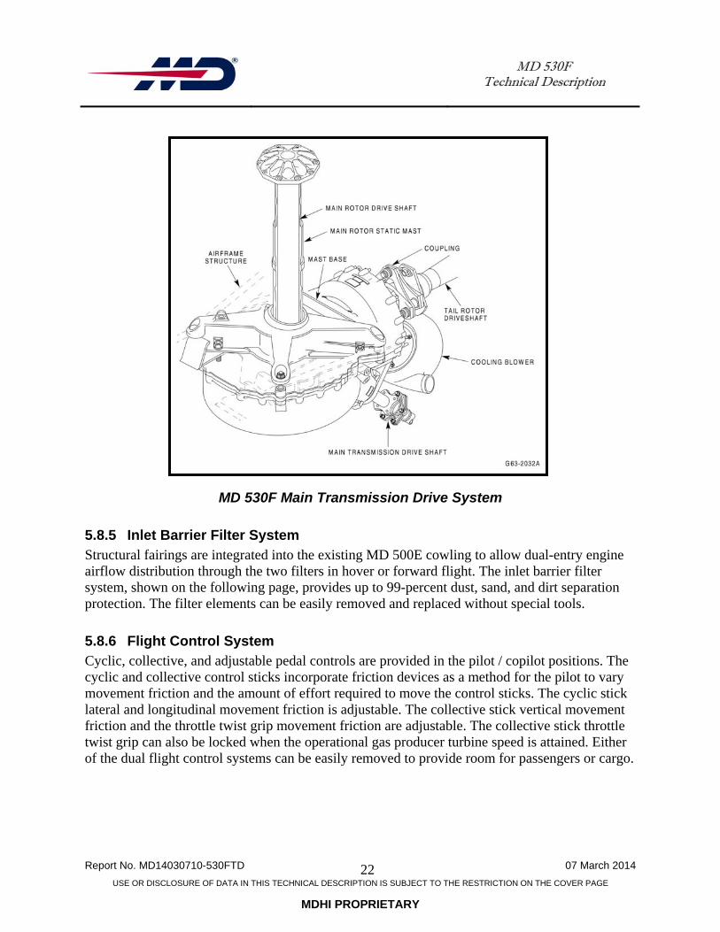
5.8.3 Drive System The MD 530F drive system, shown in the figures below, consists of an:
Main rotor static mast – Non-rotating and is rigidly mounted to the mast support structure. It provides support for the main rotor, main rotor transmission, and main rotor transmission drive shaft
Main rotor drive shaft – Transmits torque to the main rotor. Lifting loads are prevented from being imposed on the main transmission, eliminating thrust loading of transmission parts
Main rotor transmission – Mounted to the basic airframe structure above the passenger / cargo compartment, the main rotor transmission is lubricated by a self-contained air-cooled lubrication system
Overrunning clutch – The overrunning clutch transmits power from the engine to the main rotor transmission drive shaft
Main rotor transmission drive shaft – Connects to the main rotor transmission input shaft Oil Cooler – The oil cooler is a two section cooler with an upper and lower part. The
upper part is used to cool the transmission lubricating oil and the lower part is used to cool the engine lubricating oil
Oil-cooler / blower – Belt driven off the main drive shaft, it draws cooling air from the air inlet fairing to supply ambient air to the engine and transmission oil coolers and to the engine compartment
Tail rotor drive shaft – Connects the main rotor transmission and tail rotor transmission. Incorporated tail rotor drive shaft dampers reduce vibration in the tail rotor drive system
Tail rotor transmission – Mounted on the aft end of the tail boom and has a self-contained lubrication system. The tail rotor is mounted on the output shaft of the tail rotor transmission and consists of two variable-pitch blades.
5.8.4 Rotor System The static mast-hub support system, unique to MDHI products, uses a static mast, rigidly attached to the fuselage. All dynamic loads are transmitted through the mast, rather than through the transmission. A separate, inner drive shaft transmits engine torque to the main rotor hub. This feature offers improved flight control integrity and helps retain rotor system components in the event of a main rotor blade strike. Additionally, this approach allows for the design of a main transmission that is lighter in weight, and can be removed without disturbing the hub or control system. The MD 530F utilizes a five-blade, fully articulated main rotor assembly. Rotor blades, pitch housings, and links are secured to the hub by laminated steel strap sets. These sets are used in lieu of typical thrust bearing stacks to contain blade centrifugal loading and allow feathering.

MD 530F Technical Description
Report No. MD14030710-530FTD 07 March 2014
USE OR DISCLOSURE OF DATA IN THIS TECHNICAL DESCRIPTION IS SUBJECT TO THE RESTRICTION ON THE COVER PAGE
MDHI PROPRIETARY
21
The strap sets provide additional functionality: The strap set configuration (which is secured firmly to the hub) allows the centrifugal
load exerted by one blade to be countered by the force exerted by the opposite two blades, resulting in very light centrifugal loads exerted on the hub.
The V-legs of the strap set rotate as driving members to turn the main rotor blades. The strap sets are configured to allow feathering and flapping of the blades.
Main rotor blades are retained to the main rotor hub using captive cam-handle-type blade retention bolts.
MD 530F In-Situ Drive System
MD 530F Technical Description
Report No. MD14030710-530FTD 07 March 2014
USE OR DISCLOSURE OF DATA IN THIS TECHNICAL DESCRIPTION IS SUBJECT TO THE RESTRICTION ON THE COVER PAGE
MDHI PROPRIETARY
22
MD 530F Main Transmission Drive System
5.8.5 Inlet Barrier Filter System Structural fairings are integrated into the existing MD 500E cowling to allow dual-entry engine airflow distribution through the two filters in hover or forward flight. The inlet barrier filter system, shown on the following page, provides up to 99-percent dust, sand, and dirt separation protection. The filter elements can be easily removed and replaced without special tools.
5.8.6 Flight Control System Cyclic, collective, and adjustable pedal controls are provided in the pilot / copilot positions. The cyclic and collective control sticks incorporate friction devices as a method for the pilot to vary movement friction and the amount of effort required to move the control sticks. The cyclic stick lateral and longitudinal movement friction is adjustable. The collective stick vertical movement friction and the throttle twist grip movement friction are adjustable. The collective stick throttle twist grip can also be locked when the operational gas producer turbine speed is attained. Either of the dual flight control systems can be easily removed to provide room for passengers or cargo.

MD 530F Technical Description
Report No. MD14030710-530FTD 07 March 2014
USE OR DISCLOSURE OF DATA IN THIS TECHNICAL DESCRIPTION IS SUBJECT TO THE RESTRICTION ON THE COVER PAGE
MDHI PROPRIETARY
23
Inlet Barrier Filter System Consists of Two Air Filters
5.8.7 Electrical System The MD 530F electrical system is a direct current (dc) system with electrical power supplied by a 24-volt nickel-cadmium battery and a 28-volt, 85-amp engine-driven generator. The electrical system incorporates a generic electrical wire harness that is shielded to minimize electro-magnetic interference (EMI). Forward and aft line relay contacts protect main power bus and feeder wires. Over-voltage diodes protect circuits from excessive ground power voltages. An external power receptacle is available for ground power.
5.8.8 Environmental Control System Cabin environmental control is accomplished by an integral heating and defogging system and an external-air circulation system. The heating and defogging system requires no additional equipment and uses oil cooler blower supplied unheated air and turboshaft engine compressor supplied heated air. Cabin ventilation with ambient external air is available using instrument-panel-mounted mechanical controls to operate a moveable vane. In addition, adjustable window-mounted ventilators are installed in each door window to provide in-flight, outside forced air into the cabin or provide vent-air exhaust. An air conditioning system is an available option.

MD 530F Technical Description
Report No. MD14030710-530FTD 07 March 2014
USE OR DISCLOSURE OF DATA IN THIS TECHNICAL DESCRIPTION IS SUBJECT TO THE RESTRICTION ON THE COVER PAGE
MDHI PROPRIETARY
24
5.8.9 Monitoring Instrumentation Typical MD 530F monitoring instrumentation provided as standard equipment includes:
Dual engine tachometer (NR and N2) Engine oil pressure Engine oil temperature Engine torque meter Engine N1 tachometer Engine turbine outlet temperature Fuel quantity Airspeed Barometric altimeter Magnetic compass Outside air temperature Direct current ammeter Fuel quantity Digital chronometer Annunciator panel caution / warning lights
o Engine chip detector light o Engine-out warning o Fuel filter warning o Fuel-low warning o Generator-out warning o Battery over-temperature warning o Low rotor rpm warning o Main rotor transmission chip detector warning o Main rotor transmission oil pressure warning o Main rotor transmission oil temperature warning o Tail rotor transmission chip detector warning.
5.8.10 Caution / Warning Annunciators Caution and warning annunciators (indicators) are located at the top of the instrument panel above the flight instruments. A caution indication will be displayed by a yellow indicator illumination. A warning indication will be displayed by a red indicator illumination. Additionally, an audible warning tone will be presented for an engine-out and low-rotor-speed indication with the corresponding warning indicator illumination.
5.8.11 Avionics / Communications The MD 530F is provided with a standard avionics suite. Optional purchaser configured avionics, communications, instrumentation, etc., may be added at additional expense. To accommodate additional avionics / communication equipment, an optional slant console panel installation is available.

MD 530F Technical Description
Report No. MD14030710-530FTD 07 March 2014
USE OR DISCLOSURE OF DATA IN THIS TECHNICAL DESCRIPTION IS SUBJECT TO THE RESTRICTION ON THE COVER PAGE
MDHI PROPRIETARY
25
5.8.12 Next-Generation Electronic Flight Instrument System The MD 500-series helicopters will incorporate a modernized instrumentation / avionics cockpit consisting of a Garmin G500 suite that includes a multi-function and primary flight displays (MFD, PFD) and an engine indicating and crew alerting system (EICAS). The EICAS will replace the caution and warning annunciators. The next-generation electronic flight instrumentation system will work with additional equipment such as a GTN650 GPS / NAV / COM and automatic dependent surveillance-broadcast (ADS-B) to provide next-generation air transportation system compatibility.

MD 530F Technical Description
Report No. MD14030710-530FTD 07 March 2014
USE OR DISCLOSURE OF DATA IN THIS TECHNICAL DESCRIPTION IS SUBJECT TO THE RESTRICTION ON THE COVER PAGE
MDHI PROPRIETARY
26
THIS PAGE INTENTIONALLY LEFT BLANK

MD 530F Technical Description
Report No. MD14030710-530FTD 07 March 2014
USE OR DISCLOSURE OF DATA IN THIS TECHNICAL DESCRIPTION IS SUBJECT TO THE RESTRICTION ON THE COVER PAGE
MDHI PROPRIETARY
27
6. PERFORMANCE SPECIFICATION Performance specifications for the MD 530F helicopter with the standard Rolls-Royce Model 250-C30 turboshaft engine are provided below.
6.1 MD 530F – Rolls-Royce Model 250-C30 Turboshaft Engine Using the Rolls-Royce Model 250-C30 turboshaft engine, the MD 530F has a nominal empty weight of 1,591 pounds (722 kg) and a maximum gross takeoff weight of 3,100 pounds. Ratings are for the MD 530F with a Rolls-Royce 250-C30 turboshaft engine rated at 650 shp (485 kW), derated to takeoff power - 425 shp (317 kW), maximum continuous power – 350 shp (261 kW).
MD 530F Performance Specifications (Rolls-Royce Model 250-C30)
Parameter Condition Imperial Metric
Maximum Cruise Speed, kt (mph) [km/hr]
Sea Level ISA 134 (154) [248] 1524 m (5000 ft) 135 (155) [250]
Maximum Permitted Speed, kt (mph) [km/hr]
VNE at Sea Level 152 (175) [282]
Maximum Range, nm, (mi) [km] Sea Level 216 (248) [400] 1524 m (5000 ft) 260 (299) [482]
Maximum Endurance, hr Sea level , ISA 2.2 2.2
Maximum Rate-of-Climb, ft/min (m/sec)
Sea Level Standard Day
2,069 (10.5)
ISA +20C day 2,061 (10.5) Maximum Operating Altitude, ft (m)
Density altitude 20,000 (6096)
Service Ceiling, ft (m) ISA 18,700 (5700) Maximum Hook Capacity, lb (kg) 2,000 (907) Hover-in-Ground Effect (HIGE), ft (m)
Standard Day 16,000 (4877) ISA +20C Day 14,300 (4359)
Hover-Out-of-Ground (HOGE), ft (m)
Standard Day 14.400 (4389) ISA +20C Day 11,600 (3536)
Maximum Takeoff Gross Weight, lb (kg)
Normal Category 3,100 (1406) External Load Operations
3,750 (1701)
MGTOW External Load Operations, lb (kg)
2,159 (979)
Empty Weight, lb (kg) Standard Configuration 1,591 (722) Useful Load, lb (kg) Normal Capacity 1,509 (684) External Load Operations, lb (kg) 2,159 (979) Fuel Capacity, lb (kg) 64 gal (242 l) 403 (183)

MD 530F Technical Description
Report No. MD14030710-530FTD 07 March 2014
USE OR DISCLOSURE OF DATA IN THIS TECHNICAL DESCRIPTION IS SUBJECT TO THE RESTRICTION ON THE COVER PAGE
MDHI PROPRIETARY
28
6.2 Environmental Impact The MD 530F noise signature is far below the FAA and International Civil Aviation Organization (ICAO) noise requirements. The following table provides the decibel values at three MD 530F flight profiles. The figure below provides a noise level comparison (effective perceived noise level [EPNL], in decibels [dB]) for three helicopter models and the ICAO limit.
MD 530F Operational Noise Levels for Three Flight Profiles
Flight Profile Measured Value,
EPNdB ICAO Requirement Compliance Margin
Takeoff 88.6 91.4 2.8 Level Flyover 87.7 90.4 2.7 Approach / Landing 89.6 92.4 2.8
MD 530F Average Noise Certification Level Comparison

MD 530F Technical Description
Report No. MD14030710-530FTD 07 March 2014
USE OR DISCLOSURE OF DATA IN THIS TECHNICAL DESCRIPTION IS SUBJECT TO THE RESTRICTION ON THE COVER PAGE
MDHI PROPRIETARY
29
The figure on the following page provides a comparison of 500-foot overflight effective, perceived noise levels (EPNLs) of competitor twin-engine aircraft using European Aviation Safety Agency (EASA) data. This figure shows the MD 500E with four-blade tail rotor, MD 520N, and MD 600N helicopters provide the lowest EPNLs of light single-engine helicopters.
6.3 Safety The MD 530F has inherent safety features. The fuselage includes a rigid, three-dimensional truss type structure, with an integral roll-bar design for increased occupant safety. The airframe structure is designed to be energy absorbing and fails progressively in the event of impact. The fuel cells are separated well away from the outer skin, enclosed by two deep keel beams. Shoulder and seat belts are attached to the aircraft structure rather than to the seat. The pilot and cabin doors function both as primary and emergency exits. Occupant seat crush boxes are incorporated into the design and provide 20g shock resistance. The seat crush boxes were originally designed to meet Civil Aviation Regulation, Part 6 (CAR6) requirements and have been validated under Title 14 Code of Federal Regulation (CFR), Chapter 1, Part 27, Subpart C, Section 27.562 for the MD 600N air vehicle. Seat crush boxes for the MD 600N are the same as used in the MD 500-series
6.3.1 Crashworthiness The MD 530F is a derivative of the OH-6A observation helicopter used extensively by the United States Army during the Vietnam conflict in which nearly 1500 OH-6A aircraft were operated. The OH-6A earned a reputation for being the most survivable helicopter in the world, due to inherent design features shown in the figure below.
MD 500-Series Crashworthy Design Features

MD 530F Technical Description
Report No. MD14030710-530FTD 07 March 2014
USE OR DISCLOSURE OF DATA IN THIS TECHNICAL DESCRIPTION IS SUBJECT TO THE RESTRICTION ON THE COVER PAGE
MDHI PROPRIETARY
30
The MD 530F Helicopter 500-Foot Overflight Effective Perceived Noise Levels is Comparable to Light Single-Engine Helicopters

MD 530F Technical Description
Report No. MD14030710-530FTD 07 March 2014
USE OR DISCLOSURE OF DATA IN THIS TECHNICAL DESCRIPTION IS SUBJECT TO THE RESTRICTION ON THE COVER PAGE
MDHI PROPRIETARY
31
Tests on the landing gear and fuselage sections verified the crashworthiness capability of the MD 500-series. The testing indicates that the MD 500-series helicopters will provide occupant protection for approximately 95-percent of all civil accidents, and that the landing gear and airframe fuselage is capable of absorbing vertical descents up to 26.3 feet per second with only moderate crewmember injury.
6.4 Human Systems Interface The MD 530F incorporates anthropometric design features that are compatible with 25th to 95th percentile male or female crewmembers. Sizing parameters for the 25th to 95th percentile male and female are provided in the table below. The canopy design meets human engineering design requirements for windows, canopies, and windshields, as shown in the figures that follow.
Anthropometric Sizing Parameters
Parameter 25th
Percentile Female
95th Percentile
Female
25th Percentile
Male
95th Percentile
Male
Weight, lb (kg) 119.3 (54.1)
164.5 (74.5)
142.6 (64.7)
201.8 (91.5)
Height, in. (cm) 62.4
(158.5) 68.5
(174.0) 67.0
(170.1) 73.9
(187.7) Elbow – Hand Grip Reach, in. (cm)
12.5 (31.7)
14.1 (35.8)
13.7 (34.8)
15.4 (39.1)
Thumb Tip Reach, in. (cm)
27.9 (70.8)
31.4 (79.7)
30.4 (77.2)
34.2 (86.9)
Functional Leg Reach Length, in. (cm)
39.2 (99.6)
43.2 (109.7)
43.5 (110.6)
46.0 (166.8)

MD 530F Technical Description
Report No. MD14030710-530FTD 07 March 2014
USE OR DISCLOSURE OF DATA IN THIS TECHNICAL DESCRIPTION IS SUBJECT TO THE RESTRICTION ON THE COVER PAGE
MDHI PROPRIETARY
32
The MD 530F Provides a 160-Degree Vertical Unobstructed View for the Pilot and
Copilot
The MD 530F Provides a 220-Degree Horizontal Unobstructed View for the Pilot and Copilot (View is Top-Down)

MD 530F Technical Description
Report No. MD14030710-530FTD 07 March 2014
USE OR DISCLOSURE OF DATA IN THIS TECHNICAL DESCRIPTION IS SUBJECT TO THE RESTRICTION ON THE COVER PAGE
MDHI PROPRIETARY
33
7. MAINTENANCE AND SERVICING The MD 500-series helicopters were designed for ease of supportability and low-cost operation. Helicopter systems and components are easily accessed and can be maintained at the lowest maintenance level possible. The helicopter was designed for both a high level and ease of replacement of line replaceable units (LRUs). The helicopters can be maintained at the line- / shop-maintenance level using common hand tools, as well as easy-to-understand technical publications. MD 500-series helicopter spare parts are readily available, and most parts have a corresponding United States Department of Defense National Stock Number (NSN).
7.1 Maintenance The MD 530F design provides for the maximum maintenance support at the lowest maintenance level. The MD 530F can be maintained using a combination of line and shop maintenance support. Components such as engine, avionics, interior components, air conditioning, etc., are considered LRUs. Line replaceable units (and any sub-component shop replaceable units) can be removed and replaced easily and modularly, as necessary, and at the lowest maintenance level allowed. Typical for small- to mid-sized helicopter systems are fixed time-between-overhaul (TBO) intervals for the engine, transmission, main rotor, and flight controls. Included within these items are life-limited components that must be monitored and replaced at the end of life hours. When required, components requiring further maintenance action can be removed and forwarded to the appropriate-level shop. The MD 530F helicopter airframe uses an on-condition maintenance concept, which allows scheduled inspections / checks. To be compliant with commercial regulatory requirements, an MD 530F continued airworthiness inspection program was developed by MDHI. This program provides for schedule inspections, and also includes life-limited component replacement. The maintenance and inspection intervals are provided in the Handbook of Maintenance Instructions. Airframe-related inspection intervals occur every:
100 hours 300 hours 600 hours 1200 hours Yearly Special time-phase inspections.
The engine also has life-limited components, a fixed TBO, and inspection intervals. The MD 530F life-limited parts, overhaul intervals, and inspection intervals are listed in the table below.

MD 530F Technical Description
Report No. MD14030710-530FTD 07 March 2014
USE OR DISCLOSURE OF DATA IN THIS TECHNICAL DESCRIPTION IS SUBJECT TO THE RESTRICTION ON THE COVER PAGE
MDHI PROPRIETARY
34
MD 530F Life-Limited Parts, Overhaul, and Inspection Intervals
Component
Life Limit, hr
Overhaul Interval, hr
Inspection Interval, hr
Main Rotor Blade 3,430 Main Rotor Blade Pin 7,600 Main Rotor Hub Assembly 8,900
Upper/Lower Thrust Bearing Cup 2 yr / 2,770 Upper/Lower Thrust Bearing Cone 2 yr / 2,770
Main Rotor Pitch Housing 9,100 Main Rotor Retention Strap 2,770 100 Main Rotor Lead-Lag Hub Bolt 6,120 Main Rotor Lead-Lag Link Assembly 11,080 Main Rotor Swashplate 2 yr / 2,770 Main Rotor Mast Assembly 10,450 Main Rotor Transmission Drive Shaft 3,790 Main Rotor Transmission Drive Shaft Coupling
4,300
Main Rotor Transmission 5,000 Overrunning Clutch Assembly (wear check and spline re-grease)
100
Overrunning Clutch Sprag Assembly 300 Tail Rotor Drive Shaft 14,610 Tail Rotor Transmission Input Gearshaft 3,365 Tail Rotor Transmission Output Pinion Gearshaft
7,290
Tail Rotor Transmission 3,365 Tail Rotor Blade Assembly 5,140 Tail Rotor Hub 3,450 Tail Rotor Retention Strap Assembly 5,100 Tail Boom Attach Bolts 21,950 Tail Boom Assembly 10,300 Vertical Stabilizer Assembly 3,388 Horizontal Stabilizer Assembly 7,700 Longitudinal Idler Bellcrank Assembly 6,500 Starter / Generator 1,200 Oil Cooler / Blower Bearings 1,200 Oil Cooler / Blower Belt 1,200 Main Rotor Lead-Lag Dampers 600 Battery Over-Temperature Sensor 1,200 Helicopter
Interior 100 / Annually Exterior 100 / Annually Landing Gear 100 / Annually

MD 530F Technical Description
Report No. MD14030710-530FTD 07 March 2014
USE OR DISCLOSURE OF DATA IN THIS TECHNICAL DESCRIPTION IS SUBJECT TO THE RESTRICTION ON THE COVER PAGE
MDHI PROPRIETARY
35
Component
Life Limit, hr
Overhaul Interval, hr
Inspection Interval, hr
Horizontal Stabilizer 100 / Annually Vertical Stabilizer 100 / Annually Main Rotor 100 / Annually Drive Train 100 / Annually Flight Controls 100 / Annually Anti-Torque System 100 / Annually Electrical System 100 / Annually Engine Compartment 100 / Annually
Helicopter Interior 300 Exterior 300 Landing Gear 300 Main Rotor 300 Drive Train 300 Flight Controls 300 Anti-Torque System 300 Electrical System 300 Engine Compartment 300
Rolls-Royce 250-C30 Turboshaft Engine
Compressor Module 3,500 Compressor Impeller 3,550/9,150
Turbine Module 3,500 1,750 First-Stage Turbine Wheel 1,775/3,000 Second-Stage Turbine Wheel 1,775/3,000 Third-Stage Turbine Wheel 4,550/6,000 Fourth-Stage Turbine Wheel 4,550/6,000
Fuel Control 2,500 Governor 2,000 Fuel Pump 2,250 Fuel Nozzle 2,500 Compressor Bleed Valve 1,500
NOTES: Bearing grease re-pack task. Engine inspection intervals at 100, 150, 600, 1,000, and 1,500 hours are detailed in the corresponding Rolls-Royce Maintenance Manual. Value represents hours / cycles. Hot section inspection. Detailed maintenance / inspection information is provided in the Handbook of Maintenance Instructions, Rotorcraft Flight Manual, and Supplier Technical Publications (Rolls-Royce).

MD 530F Technical Description
Report No. MD14030710-530FTD 07 March 2014
USE OR DISCLOSURE OF DATA IN THIS TECHNICAL DESCRIPTION IS SUBJECT TO THE RESTRICTION ON THE COVER PAGE
MDHI PROPRIETARY
36
7.2 Servicing The MD 530F was designed for ease of maintenance, incorporating built-in features that eliminate support equipment and aid servicing. These features include:
Spring loaded doors that provide engine and main rotor head access (refer to figure below)
Quick access panels Integrated diagnostics Integrated engine water wash system.
The MD 530F has Built-in Steps to Provide Access to the Main Rotor Head without External Ground Support

MD 530F Technical Description
Report No. MD14030710-530FTD 07 March 2014
USE OR DISCLOSURE OF DATA IN THIS TECHNICAL DESCRIPTION IS SUBJECT TO THE RESTRICTION ON THE COVER PAGE
MDHI PROPRIETARY
37
The MD 530F helicopter has been designed for servicing and operation using common, commercially-available compounds. Servicing locations are shown in the figure below, and will be performed in accordance with the corresponding equipment maintenance manuals. Servicing intervals are detailed in the MD 530F Handbook of Maintenance Instructions. Capacities and compounds used to service the MD 530F are listed in the table on the following page.
MD 530F Servicing Location Points

MD 530F Technical Description
Report No. MD14030710-530FTD 07 March 2014
USE OR DISCLOSURE OF DATA IN THIS TECHNICAL DESCRIPTION IS SUBJECT TO THE RESTRICTION ON THE COVER PAGE
MDHI PROPRIETARY
38
MD 530F Fluid Capacities and Specifications
Component Compound Capacity Specification Notes
Engine Lubricant 3.0 quarts (2.84 liters)
MIL-PRF7808G / MIL-PRF-23699C
Overrunning Clutch
Lubricant 3.64 ounces (107 cc)
Mobil AGL
Main Rotor Transmission
Lubricant 14.0 pints 6.62 liters)
Mobil AGL
Tail Rotor Transmission
Lubricant 0.5 pint (0.23 liter)
Mobil AGL
One-Way Lock
Lubricant 0.67 ounces (20 cc)
MIL-PRF-5606 / MIL-PRF-6083
Battery Distilled Water
As Required MS36300
Fuel Cell Fuel 64.0 gallons (242 liters) 416 pounds
ASTM-D-1655, Jet A ASTM-D-1655, Jet A-1 ASTM-D-1655, Jet B ASTM-D-1655, JP-1 ASTM-D-1655, RP-3 ASTM-D-6615, Jet B MIL-DTL-5624, JP-4 MIL-DTL-5624, JP-5 MIL-DTL-83133, JP-8
NOTES: Refer to Rolls-Royce Operation and Maintenance Manual for approved oils. Oil specification type mandated by ambient temperature. Refer to Rolls-Royce Operation and Maintenance Manual. Refer to Rolls-Royce Operation and Maintenance Manual for complete fuel specifications. At 40F and below, fuel must contain anti-icing additives per MIL-I-17686. Refer to Rolls Royce Operation and Maintenance Manual.
7.3 Hourly Cost Current, estimated direct operating cost per operating hour data using the Rolls-Royce Model 250-C30 are shown in the following table. This data is based on “current-year” 2014 U.S. dollars.

MD 530F Technical Description
Report No. MD14030710-530FTD 07 March 2014
USE OR DISCLOSURE OF DATA IN THIS TECHNICAL DESCRIPTION IS SUBJECT TO THE RESTRICTION ON THE COVER PAGE
MDHI PROPRIETARY
39
MD 530F Estimated Direct Operating Cost Per Operating Hour is Based on Current-Year (2014) U.S. Dollars
Activity Cost, U.S
Dollars ($) Total
Rolls-Royce Model 250-C30 Engine Fuel and Lubricants
Fuel at $3.93 at approximately 35 gallons per hour $137.55 Lubricants at 3-percent of fuel $4.13
$141.68Airframe Maintenance and Spares
Maintenance Labor Cost: Scheduled (0.15 man-hour per flight hour at $75.00 per hour) $11.25 Unscheduled (0.26 man-hour per flight hour at $75.00 per hour) $19.50
$30.75Spares Cost: Scheduled (Inspection) Parts: used during Periodic Inspection (e.g., filters, seals, o-rings, etc.)
$5.78
On-Condition / Unscheduled Part $21.12 Reserves: Component Overhaul (Time Between Overhaul) $82.66 Reserves: Life-Limited Parts $58.75
$168.31Engine
Scheduled Maintenance Labor and Parts $3.00 Reserves for Engine Overhaul, Spares, Accessories $116.70
$119.70
TOTAL DIRECT OPERATING COST $460.44
NOTES: Fuel cost and labor rate are based on U.S. average cost while operating under the following conditions:
Gross Weight: 10 percent less than the maximum certified Speed: Maximum range speed, 124 kias Altitude: 1,000 feet (304 m) on a standard day.
Overhaul costs are based on participation in factory exchange program. Engine fleet maintenance costs are provided by Rolls-Royce. Indirect costs such as insurance, hangar, salary, etc. are not included. Actual costs will vary depending on local operating conditions, pricing, and supplier practices.

MD 530F Technical Description
Report No. MD14030710-530FTD 07 March 2014
USE OR DISCLOSURE OF DATA IN THIS TECHNICAL DESCRIPTION IS SUBJECT TO THE RESTRICTION ON THE COVER PAGE
MDHI PROPRIETARY
40
THIS PAGE INTENTIONALLY LEFT BLANK

MD 530F Technical Description
Report No. MD14030710-530FTD 07 March 2014
USE OR DISCLOSURE OF DATA IN THIS TECHNICAL DESCRIPTION IS SUBJECT TO THE RESTRICTION ON THE COVER PAGE
MDHI PROPRIETARY
41
8. PRODUCT SUPPORT MD Helicopters, Inc. is dedicated to a successful fielding, training, warranty support, and customer support of MDHI aircraft. MD Helicopters, Inc. has worldwide service centers and field service representatives available for localized support.
8.1 Training The MDHI commercial training center offers cost-effective, factory-designed transition-flight and maintenance-crew training courses for MDHI-manufactured helicopters. This training, conducted by senior instructors with extensive product experience, provides customers / students with the detailed knowledge of MDHI products that will increase safety, reduce insurance costs, and result in more efficient operation of the aircraft. Training is conducted at the MDHI facility in Mesa, Arizona. Training using customer aircraft can also be arranged provided insurance, meeting MDHI requirements, is available.
8.1.1 Pilot Training Transition flight, maintenance test, and recurrent pilot training are available from MDHI. Flight transition pilot training for one pilot is included as part of each MDHI helicopter purchase.
8.1.2 Transition Flight Training The transition flight training course is designed to familiarize a rated helicopter pilot with operation of the MDHI aircraft. The transition flight training course is a five-day course that introduces the student to all the associated company publications, as well as detailed explanations of all aircraft systems and daily / preflight procedures. The ground school requires 16 to 20 hours to complete, including examination and examination review. The student is expected to pass the examination, demonstrating basic knowledge of the aircraft. The transition flight training syllabus includes six hours of instructor time and is provided in four flight lessons:
Normal operations Advanced operations (maximum gross weight flight) Maintenance and systems operations Emergency / malfunction procedures.
8.1.3 Recurrent Flight Training Additional, optional, recurrent pilot training is available for existing MD 530F pilots. Recurrent pilot training provides a pilot review of MD 530F helicopter systems and operations, and uses flight review, proficiency checks, or other checks to review rules, maneuvers, and procedures to demonstrate existing pilot skills. Training is conducted over a three-day period and consists of ground school and two to three hours of flight time. Ground school training includes a review and discussion of airworthiness directives and notices, helicopter systems, flight manual review, preflight inspection, followed by an open-book examination.

MD 530F Technical Description
Report No. MD14030710-530FTD 07 March 2014
USE OR DISCLOSURE OF DATA IN THIS TECHNICAL DESCRIPTION IS SUBJECT TO THE RESTRICTION ON THE COVER PAGE
MDHI PROPRIETARY
42
8.1.4 Maintenance Training The airframe maintenance course familiarizes a licensed aircraft and powerplant mechanic with the maintenance and inspection of aircraft major systems. Training adheres to original equipment manufacturer standards and includes an overview of supporting maintenance documentation, service bulletins, service letters, and maintenance logbook. All training materials required to conduct maintainer training (i.e., instructional materials, handouts, presentations, training guides / aids, tests / exercises) are returned to each trainee. Hands-on training using MDHI- or customer-furnished equipment will be provided as necessary to supplement the classroom instruction. Training instruction and technical information are conducted in the English language. Course syllabus includes:
Airframe Flight control system Environmental control system Power train Rotor system.
Maintainer training for one maintainer is provided as part of the helicopter purchase.
8.2 Warranty The MD 530F commercial helicopters are covered by a commercial warranty which is administered by MDHI Mesa, Arizona. Supplier products (e.g., turboshaft engine, avionics, etc.) are separately warranted through the product supplier. The MDHI Commercial Warranty is a materials and workmanship type warranty that begins upon customer helicopter / spare parts acceptance / delivery. The customer will perform prompt repair or replacement of helicopter specific discrepant hardware. For warranty claims pertaining to aftermarket spare parts and components, the customer, at their option (with prior approval), either:
Returns the non-conforming or defective part or component for credit or refund; or Requests correction or replacement of the affected part or component. Associated
shipping costs shall be shared by the customer and the vendor.
8.2.1 Warranty Claims All warranty claims begin with completion of an MDHI service and operations report (SOR) document. The completed SOR document is submitted to MDHI field services for technical accuracy and completeness review and to determine if additional action is needed. When the review is completed, the SOR is forwarded to the MDHI warranty / repair department for determination of warranty claim status. The circumstances of the failure, aircraft and component time, date of submittal and nature of the claim, and other factors, are evaluated in accordance with the current published MDHI warranty. The limited commercial warranty (CSP-A-2) and SOR forms can be accessed through the MDHI website.

MD 530F Technical Description
Report No. MD14030710-530FTD 07 March 2014
USE OR DISCLOSURE OF DATA IN THIS TECHNICAL DESCRIPTION IS SUBJECT TO THE RESTRICTION ON THE COVER PAGE
MDHI PROPRIETARY
43
8.3 Service Centers MD Helicopters, Inc. has approved service centers located worldwide. The figure below shows MDHI worldwide approved service centers locations. Detailed service center information is provided on the MD Helicopters customer support section of the MD Helicopters website.
8.4 Field Service Dedicated Field Service Representatives are available to support fielded MDHI products. Field Service Representatives are available for the following locations:
Asia / India / Australia / New Zealand Eastern North America Middle East / Africa Mexico /Central America / South America Russia / Commonwealth of Independent States Western North America.

MD 530F Technical Description
Report No. MD14030710-530FTD 07 March 2014
USE OR DISCLOSURE OF DATA IN THIS TECHNICAL DESCRIPTION IS SUBJECT TO THE RESTRICTION ON THE COVER PAGE
MDHI PROPRIETARY
44
MD Helicopters, Inc. Worldwide Service Center Locations