Embed Size (px)
Citation preview

technical datasheettechnical datasheet
Zone 2 hazardous area and connected to intrinsically safe equipment in a Zone 0 or 1, or Division 1 hazardous area.
In Process Automation it is also preferable to use a single cable to provide both power and communications to the end device. The 9460-ET Series can deliver Intrinsically Safe Power over Ethernet (PoEx™) with a single Cat 5e or Cat 6 cable, allowing live connection and disconnection of the end device in Zone 0 and 1 hazardous areas.
The 9461-ET Ethernet Gateway provides existing intrinsically safe equipment with “Ethernet connectivity” by allowing conventional serial communication equipment to be connected to an Ethernet network. Many intrinsically safe devices such as analysers, weighing systems, dust monitors, etc. have RS232, RS422 or RS485 serial connectivity. Providing these devices with Ethernet connectivity offers considerable hardware and integration cost savings.
The 9465-ET Copper to Fibre Optic Media Converter enables an Ethernet network to be extended over a much greater distance. A multi mode fibre optic link running at 100Mbps can go distances of up to
2 km, or an extended distance of 5 km is achievable at 10Mbps. With single mode fibre longer distances are supported.
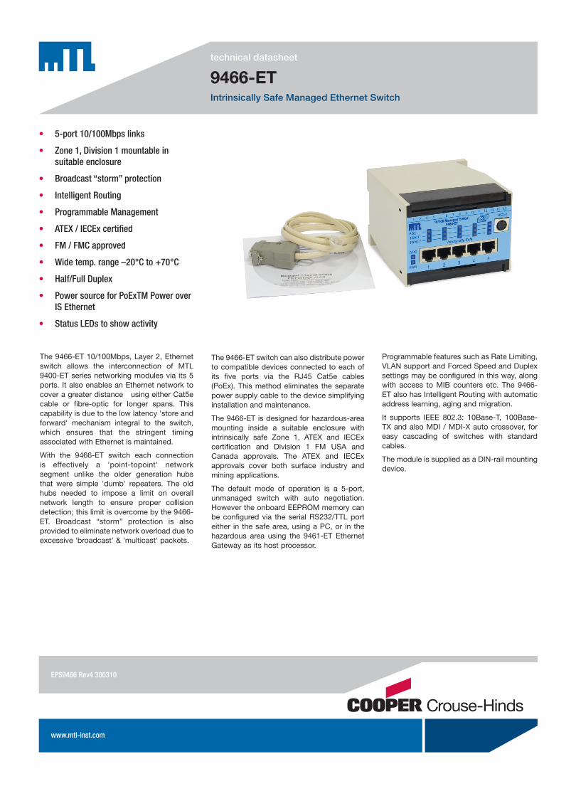
The 9466-ET Ethernet switch allows the interconnection of intrinsically safe Ethernet networking components via its 5 ports. It also enables a copper Ethernet network to be extended beyond the 100 metre distance limit between Ethernet devices.
The 9468-ET is an intrinsically safe Ethernet isolator enabling Ethernet devices in Zone 2, or a safe area, to communicate with intrinsically safe Ethernet networking components operating in the hazardous area. A further application is the use of a pair of 9468-ET isolators to permit an Ethernet cable to cross a hazardous area.
The 9469-ET Intrinsically safe Wireless LAN product is a multi-functional module that can be used as an 802.11a/b/g/h Access Point, a Wireless Bridge or a Wireless Repeater. Many end users have recognised the benefits of giving mobile operators access to control and maintenance system data.
Today in Process Automation many different methods are used to power and to communicate with end devices. Such methods may include 4-20mA; a variety of different fieldbus standards; serial communications - including RS232, RS422 and RS485; video; telephony and Ethernet.
Where applications require high bandwidth, Ethernet is the ideal solution as it provides open connectivity and can be combined with Ethernet Remote I/O and Linking Devices to connect to low bandwidth 4-20mA and fieldbus systems. But Ethernet has rarely been used in hazardous areas because of the high cost involved and the limitations involved in order to carry out maintenance.
The 9460-ET Series provides cost-effective Intrinsically Safe (IS) Ethernet equipment that can be installed and maintained easily in hazardous areas. The intrinsically safe hazardous area certification permits the components to be mounted in a Zone 1, or Division 1 hazardous area with connectivity into Zone 0 and the associated apparatus certification of the 9468-ET IS Ethernet isolator and 9491-PS IS power supply allow this equipment to be mounted in a
• CosteffectiveISEthernetequipmentforZone1,Division1hazardousareas
• ConnectivityintoZone0
• IntrinsicallysafePoweroverEthernet(PoEx™)enablesliveconnectionordisconnectioninZone0and1
• Serial-to-EthernetGateway
• CoppertoFibre-OpticMediaConverter
• ISEthernetSwitch
• ISEthernetIsolator
• ISWirelessLANAccessPoint/Bridge
9460-ET SeriesIntrinsically safe Ethernet products
EPS9460Rev4300310

EUROPE (EMEA): +44 (0)1582 723633 THE AMERICAS: +1 800 835 7075 ASIA-PACIFIC: +65 6 487 7887
[email protected] [email protected] [email protected]
A choice of intrinsically safe PDAs and Zone 2 PCs offering 802.11 wireless connectivity is now available. The 9469-ET offers lower costs and easier maintenance for WLAN equipment installed in hazardous areas, compared to the alternative of large, expensive flameproof enclosures fitted with specialist certified antennas.
The 9491-PS Power Supply is the preferred method for supplying the 9460-ET Series of IS Ethernet Modules as it is based on an isolating power supply. It takes a 24V DC Safe Area/Zone 2 supply and produces an Intrinsically Safe 12V DC nominal output capable of powering the Ethernet modules mounted in a Zone 1/Division 1 hazardous area.
The 9466-ET Ethernet Switch and the 9468-ET IS Ethernet Isolator are capable of distributing power to compatible devices connected to their IS ports providing Power over Intrinsically Safe Ethernet (PoEx™) via the RJ45 Cat5e cables. This method eliminates the need for a separate power supply cable to each Ethernet device; simplifying both installation and maintenance. A 9491-PS power supply is required to power the 9466-ET and an additional 9491-PS is required for each powered Ethernet port. Similarly, one 9491-PS is required to power the IS Ethernet port of the 9468-ET IS Ethernet Isolator. The 9461-ET, 9465-ET and 9469-ET can be powered directly from a 9491-PS intrinsically safe power supply or using Power over IS Ethernet (PoEx™).
The MTL IS Ethernet applications range from immediate needs for Hazardous Area WLAN infrastructure; IS serial device connectivity; and Ethernet connections across hazardous areas to long term opportunities to develop Ethernet field devices.
APPLICATIONS
9461-ET Ethernet Gateway connects to instrinsically safe RS232, RS422 and RS485 devices
9469-ET Wireless LAN Access Point connects to a wide choice of IS PDAs and Zone 2 PCs
9466-ET Ethernet Switch connects directly to Intrinsically Safe Ethernet devices
EPS9460 Rev4 300310

technical datasheettechnical datasheet
9461-ETIntrinsically Safe Serial to Ethernet Gateway
• SerialtoEthernetGateway
• Zone1,Division1mountableinsuitableenclosure
• Fourserial-portintrinsicallysafeinputs: 2xRS232/TTL 2xRS485/RS422
• 10/100MbsEthernet
• ATEX/IECExcertified
• FM/FMCapproved
• Widetemp.range–20°Cto+70°C
• HighPerformance32-bitprocessor
• PoEx™PoweroverISEthernetoption
The 9461-ET Ethernet Gateway gives existing intrinsically safe equipment “Ethernet connectivity” by allowing conventional serial communication port equipment to be connected to an Ethernet network.
Two 9-way D-type serial ports are provided which are RS232/TTL compatible. In addition, the module’s front panel screw terminals (T6 - T15) provide two RS485/RS422, 2- or 4- wire ports, giving a total of four serial ports. All ports can operate at speeds up to 115K2baud.
Various protocols are available (eg: Serial Modbus, Modbus/TCP, Ethernet IP etc) in addition to Serial Tunnelling.
The 9461-ET is designed for hazardous-area mounting inside a suitable enclosure with intrinsically safe Zone 1, ATEX and IECEx certification and Division 1 FM USA and Canada approvals. The ATEX and IECEx approvals cover both surface industry and mining applications.
The design is based on a high performance ARM9 155MHz 32-bit RISC Processor (ARM926EJ-S).
The gateway may be powered by an intrinsically safe power supply or by Power over IS Ethernet (PoEx) providing intrinsically safe power and Ethernet communications over a single Cat5e cable.
10/100Mb Ethernet twisted pair (Cat5e) RJ45 connection (100metres length max).
Status LEDs are provided on the front panel to indicate:
• ’Power On’
• Network Link established
• Tx/Rx activity for all COM ports
Configuration is via a Microsoft® Windows™ interface which enables the IP address and the protocol conversion to be defined.
The Gateway can also act as the host processor for the 9466-ET Managed Ethernet Switch giving remote access to the switch's management features over the Ethernet network.
The module is supplied as a DIN-rail mounting device.
EPS9461Rev4300310

EUROPE (EMEA): +44 (0)1582 723633 THE AMERICAS: +1 800 835 7075 ASIA-PACIFIC: +65 6 487 7887
[email protected] [email protected] [email protected]
The given data is only intended as a product description and should not be regarded as a legal warranty of proper-ties or guarantee. In the interest of further technical developments, we reserve the right to make design changes.
SPECIFICATIONSee also System Specification
POWER INPUTPoEx or separately poweredInput voltage
12V DC (10–15.4V)Input current
150mAInput protection
Fuse + supply reversal diode
ETHERNETIntrinsically Safe 10/100 base T
ConnectorRJ45
PoExPowered Device
IS SERIAL CONNECTIONS
RS232 RS422/485
No. of channels 2 2
Connector Type DB-9 male Screw terminals
Baudrate 300-115K2 baud 300-115K2 baud
Parity Even/Odd/None Even/Odd/None
Data Bits 8 8
Stop Bits 1 1
Flow Control RTS/CTS/XON/XOFF XON/XOFF
RS232 Pin 9 power output
SAFETY
Location of moduleZone 1, IIC T4 hazardous areaor Class 1, Div 1, Groups A, B, C, D T4 hazardous location
Location of field wiringZone 0, IIC T4 hazardous areaor Class 1, Div 1, Groups A, B, C, D T4 hazardous location
Ethernet protectionIntrinsically safe
Certification CodeSee approvals
Safety descriptionSee certificate
MECHANICALMounting
DIN railDimensions (mm)
Length 75W idth 100Height (off rail) 116
Weight1200 g
LED INDICATORS OFF FLASH ON
PWR (green)
Power fail N/A Power OK
WDG (red)
Watchdog Fault Healthy (10Hz) Watchdog Fault
TX (x4) (green)
Idle Transmitting Serial Data
N/A
RX (x4) (red)
Idle Receiving Serial Data
Fault – RX data polarity is inverted
STAT (red)
Status is Normal Not used at present
Not used at present
ACT (yellow)
Ethernet link disconnected
Ethernet link activity
Ethernet link connected
100 (green)
Ethernet link set to 10Mbps
N/A Ethernet link is 100Mbps
ENVIRONMENTALAmbient temp
Operating –20°C to +70°CStorage –20°C to +70°C
Relative Humidity5 to 95% RH (non-condensing)
Ingress ProtectionSelect enclosure to suit application, see certificate for information
DATA & POWER TERMINALS
COM 1 & 2 (DB-9 male)RS232/TTL Ports
Pin Function
1 DCD
2 RxD
3 TxD
4 RS232/TTL *
5 Signal Ground 0V
6 N/C
7 RTS
8 N/C
9 +5V o/p
LAN (RJ45)10/100 BASE-T Ethernet
Pin Function
1 Tx +
2 Tx –
3 Rx +
4 Supply 12V - PoEx †
5 Supply 12V - PoEx †
6 Rx –
7 Supply 0V - PoEx †
8 Supply 0V - PoEx †
Screw Terminals †
PWR Function Terminals 1+2 and 3+4 are linked internally.
† When using PoEx, no supply is required on screw terminals 1 to 4
1 +12V DC in
2 +12V DC in
3 0V
4 0V
COM3 COM4 RS485 RS422
6 11 + Tx/Rx Tx +
7 12 – Tx/Rx Tx –
8 13 – Rx +
9 14 – Rx –
10 15 Signal Ground 0V
* Pin 4 - O/C for RS232, connect to pin 5 for TTL levels
����������������������
���������� �����
�
����������
�������������
EPS9461 Rev4 300310

technical datasheettechnical datasheet
9465-ETCopper to Fibre Intrinsically Safe Converter
• CoppertoFibreOpticConverter
• 10/100Mbpswirespeed
• Extendupto5km(10Mbs)
• Zone1,Division1mountableinsuitableenclosure
• Transparentoperation
• Choiceoffibreopticconnectionstyles
• ATEX/IECExcertified
• FM/FMCapproved
• Widetemp.range–20°Cto+70°C
• PoEx™PoweroverISEthernetoption
The 9465-ET 10/100Mbps Copper to Fibre Optic Media Converter allows an Ethernet network to be extended over a greater distance. A multi-mode fibre optic link may be up to 2km in length when running at 100Mbps and due to the use of 1300nm optics an extended distance of 5km is achievable at 10Mbps. Longer distances are achievable with single mode fibre.
Longer distances are obtained by simply connecting a 9466 (10/100Mbps Ethernet Switch) between two 9465 media converters, effectively giving a 'repeater' function (This also provides 3x UTP ports available for local network connectivity), this can be repeated as required.
The use of fibre optics gives exceptional immunity to noise and electrical interference, it is also used when connecting a Hazardous Area network to a Zone 2 / Safe Area network or device.
The 9465-ET is designed for hazardous-area mounting inside a suitable enclosure with intrinsically safe Zone 1, ATEX and IECEx certification and Division 1 FM USA and Canada approvals. The ATEX and IECEx approvals cover both surface industry and mining applications.
Fibre Optic connection options:
• ST style 62.5/125µm Multimode (9465-ET-M-ST)
• SC style 62.5/125µm Multimode (9465-ET-M-SC)
• SC style 9µm Single-mode (9465-ET-S-SC)
When installed in a Zone 1 or Division 1 hazardous area the converter may be powered by an intrinsically safe power supply or by Power over IS Ethernet (PoEx) providing intrinsically safe power and Ethernet communications over a single Cat5e cable.
When mounted in a safe area the converter may be powered by a 12V dc general-purpose power supply and the 'IS op' approval allows connection of the fibre optic cable into the hazardous area.
Status LEDs are provided on the front panel to indicate:
• 'Power On'
• Fibre Optic 'Link 10Mb or 100Mb' established
• Fibre Optic 'Tx/Rx Activity'
• Copper UTP 'Link 10Mb or 100Mb' established
• Copper UTP 'Tx/Rx Activity'
10/100Mb Ethernet twisted pair (Cat5e) RJ45 connection (100metres length max).
Transparent operatwion - 10/100Mbps, Full/Half Duplex with Auto-Negotiation. Supports IEEE 802.3: 10Base-T, 10Base-FL, 100Base-TX and 100Base-FX/SX.
The module is supplied as a DIN-rail mounting device.
EPS9465Rev4300310

EUROPE (EMEA): +44 (0)1582 723633 THE AMERICAS: +1 800 835 7075 ASIA-PACIFIC: +65 6 487 7887
[email protected] [email protected] [email protected]
The given data is only intended as a product description and should not be regarded as a legal warranty of proper-ties or guarantee. In the interest of further technical developments, we reserve the right to make design changes.
SPECIFICATIONSee also System Specification
POWER INPUTPoEx or separately poweredInput voltage
12V DC (10–15.4V)Input current
160mAInput protection
Fuse + supply reversal diode
ETHERNETIntrinsically Safe 10/100 base TConnector
RJ45PoEx
Powered Device
FIBRE PORT10/100 base FX
ConnectorSC or ST (multi-mode), SC (single-mode)OPTICAL FIBRE
Multi mode distance2Km @100Mbps / 5Km@10Mbps typ. (62.5/125)
Single mode distanceT.B.A.
TX Output (1300nm)Multi mode -19dBm (min), -14dBm (max) *note1Single mode -15dBm (min), -8dBm (max) *note2
RX SensitivityMulti mode -33.9dBm (ave), -31dBm (min)Single mode -25dBm (min)
*note1 – transmit power coupled into 62.5/125um fibre, NA=0.275*note2 – transmit power coupled into single-mode fibre
SAFETYEye Safety
Class1 Laser/LED productLocation of module
Zone 1, IIC T4 hazardous areaor Class 1, Div 1, Groups A, B, C, D T4 hazardous location
Location of field wiringZone 0, IIC T4 hazardous areaor Class 1, Div 1, Groups A, B, C, D T4 hazardous location
Ethernet protectionintrinsically safe
Fibre optic protectioninherently safe
Certification CodeSee approvals
Safety descriptionSee certificate
MECHANICALMounting
DIN railDimensions (mm)
Length 75Width 55Height (off rail) 116
Weight700 g
LED INDICATORS OFF FLASH ON
PWR (green)
Power fail N/A Power OK
ACT (red)
Idle Ethernet link activity
Ethernet link activity
10 (yellow)
No Ethernet link at 10Mbps
Poor link Ethernet connected at 10Mbps
100 (green)
No Ethernet link at 100Mbps
Poor link Ethernet connected at 100Mbps
ENVIRONMENTALAmbient temp
Operating –20°C to +70°CStorage –20°C to +70°C
Relative Humidity5 to 95% RH (non-condensing)
Ingress ProtectionSelect enclosure to suit application, see certificate for information
DATA & POWER TERMINALSLAN (RJ45)10/100 BASE-T Ethernet(TX/RX crossed MDI-X)
Pin Function
1 Rx +
2 Rx –
3 Tx +
4 Supply 12V - PoEx †
5 Supply 12V - PoEx †
6 Tx –
7 Supply 0V - PoEx †
8 Supply 0V - PoEx †
10/100 BASE-FL EthernetST(or SC) - Fibre Optic
Top Port TXBottom Port RX
Screw Terminals †
PWR Function Terminals 1+2 and 3+4 are linked internally.
† When using PoEx, no supply is required on screw terminals 1 to 4
1 +12V DC in
2 +12V DC in
3 0V
4 0V
5-8 No connections
EPS9465 Rev4 300310
technical datasheettechnical datasheet
9466-ETIntrinsically Safe Managed Ethernet Switch
• 5-port10/100Mbpslinks
• Zone1,Division1mountableinsuitableenclosure
• Broadcast“storm”protection
• IntelligentRouting
• ProgrammableManagement
• ATEX/IECExcertified
• FM/FMCapproved
• Widetemp.range–20°Cto+70°C
• Half/FullDuplex
• PowersourceforPoExTMPoweroverISEthernet
• StatusLEDstoshowactivity
The 9466-ET 10/100Mbps, Layer 2, Ethernet switch allows the interconnection of MTL 9400-ET series networking modules via its 5 ports. It also enables an Ethernet network to cover a greater distance using either Cat5e cable or fibre-optic for longer spans. This capability is due to the low latency 'store and forward' mechanism integral to the switch, which ensures that the stringent timing associated with Ethernet is maintained.
With the 9466-ET switch each connection is effectively a 'point-topoint' network segment unlike the older generation hubs that were simple 'dumb' repeaters. The old hubs needed to impose a limit on overall network length to ensure proper collision detection; this limit is overcome by the 9466-ET. Broadcast “storm” protection is also provided to eliminate network overload due to excessive 'broadcast' & 'multicast' packets.
The 9466-ET switch can also distribute power to compatible devices connected to each of its five ports via the RJ45 Cat5e cables (PoEx). This method eliminates the separate power supply cable to the device simplifying installation and maintenance.
The 9466-ET is designed for hazardous-area mounting inside a suitable enclosure with intrinsically safe Zone 1, ATEX and IECEx certification and Division 1 FM USA and Canada approvals. The ATEX and IECEx approvals cover both surface industry and mining applications.
The default mode of operation is a 5-port, unmanaged switch with auto negotiation. However the onboard EEPROM memory can be configured via the serial RS232/TTL port either in the safe area, using a PC, or in the hazardous area using the 9461-ET Ethernet Gateway as its host processor.
Programmable features such as Rate Limiting, VLAN support and Forced Speed and Duplex settings may be configured in this way, along with access to MIB counters etc. The 9466-ET also has Intelligent Routing with automatic address learning, aging and migration.
It supports IEEE 802.3: 10Base-T, 100Base-TX and also MDI / MDI-X auto crossover, for easy cascading of switches with standard cables.
The module is supplied as a DIN-rail mounting device.
EPS9466Rev4300310

EUROPE (EMEA): +44 (0)1582 723633 THE AMERICAS: +1 800 835 7075 ASIA-PACIFIC: +65 6 487 7887
[email protected] [email protected] [email protected]
The given data is only intended as a product description and should not be regarded as a legal warranty of proper-ties or guarantee. In the interest of further technical developments, we reserve the right to make design changes.
SPECIFICATIONSee also System Specification
POWER INPUTSeparately poweredInput voltage
12V DC (10–15.4V)Input current
200mAInput protection
Fuse + supply reversal diode
ETHERNETIntrinsically Safe 10/100 base T, auto negotiation speed and X-overPorts
5Connector
RJ45PoEx
Power Source Equipment, each port selectable by connection of IS power supply such as 9491-IS
TECHNOLOGYStandards
IEEE802.3, 802.3u, 802.3x, 802.1d, 802.1p, 802.1qProtocols
IGMP V1/V2 deviceMIB Counters
(via RS232 port)Flow Control
IEEE802.3x flow control, back pressure flow control
IS RS232 MANAGED SWITCH CONNECTIONNumber of channels
1Connector Type
8-pin mini-DINBaudrate
115K2baudParity
NoneData Bits
8Stop Bits
1Flow Control
None
SAFETYLocation of module
Zone 1, IIC T4 hazardous areaor Class 1, Div 1, Groups A, B, C, D T4 hazardous location
Location of field wiringZone 0, IIC T4 hazardous areaor Class 1, Div 1, Groups A, B, C, D T4 hazardous location
Ethernet protectionintrinsically safe
Certification CodeSee approvals
Safety descriptionSee certificate
MECHANICALMounting
DIN railDimensions (mm)
Length 75Width 100Height (off rail) 116
Weight1200 g
LED INDICATORS OFF FLASH ON
PWR (green)
Power fail N/A Power OK
WDG (red)
Watchdog Fault Healthy (10Hz) Watchdog Fault
FDX (red)
Half Duplex N/A Full Duplex
10 ACT (yellow)
No Ethernet link at 10Mbps
Ethernet connected and activity at 10Mbps
Ethernet connected at 10Mbps
100 ACT (green)
No Ethernet link at 100Mbps
Ethernet connected and activity at 100Mbps
Ethernet connected at 100Mbps
ENVIRONMENTALAmbient temp
Operating –20°C to +70°CStorage –20°C to +70°C
Relative Humidity5 to 95% RH (non-condensing)
Ingress ProtectionSelect enclosure to suit application, see certificate for information
DATA & POWER TERMINALSWLAN PORTS (RJ45) 10/100 BASE-T Ethernet
Pin Function
All five RJ45 ports
are identical.
1 Tx +
2 Tx –
3 Rx +
4 Supply 12V - PoEx †
5 Supply 12V - PoEx †
6 Rx –
7 Supply 0V - PoEx †
8 Supply 0V - PoEx †
Screw Terminals
Terminal Function
Notes:
1. Terminals 1+2 and 3+4 are linked internally
2. When using PoEx – ‘inject’ device power into terminals 6 to 15 as required
1 +12V DC in
9466 module supply input
2 +12V DC in
3 0V
4 0V
5 No Connection
6 +12V DC in(PoEx – Port1)
7 0V
8 +12V DC in(PoEx – Port2)
9 0V
10 +12V DC in(PoEx – Port3)
11 0V
12 +12V DC in(PoEx – Port4)
13 0V
14 +12V DC in(PoEx – Port5)
15 0V
EPS9466 Rev4 300310

technical datasheettechnical datasheet
9468-ETIntrinsically Safe Ethernet Isolator
• Zone2mountableforconnectionstoZone0and1
• GalvanicallyisolatedRJ45ports
• Transparentoperation
• Compactalternativesolutiontofibreopticsandmediaconverters
• ATEX/IECExcertified
• FM/FMCapproved
• Widetemp.range–20°Cto+70°C
• Single20–30VDCpowersupply
• StatusLEDstoshowactivity
The 9468-ET 10/100Mbps, Isolating Ethernet Barrier allows the interconnection of a Zone 2 or un-certified safe area device to the intrinsically safe 9400-ET series of Ethernet networking products, operating in the hazardous area.
The isolating barrier provides a compact alternative solution to fibre optic cable and media converters and for when it is desirable to use Cat5e cables in preference to fibre.
The 9468-ET is designed for Zone 2 hazardous-area mounting inside a suitable enclosure and has intrinsically safe ATEX and IECEx approvals, together with IS approval for USA and Canada. FM Division 2 mounting approval is pending. The ATEX and IECEx approvals cover both surface industry and mining applications.
10/100Mb Ethernet twisted pair (Cat5e) RJ45 connections (100metres length max). These RJ45 ports provide total galvanic isolation (Um=253Vac) from safe to hazardous areas.
Status LEDs are provided on the front panel to indicate:
• 'Power On'
• Safe Area UTP 'Link 10/100Mb' established
• Safe Area UTP 'Tx/Rx Activity'
• Haz. Area UTP 'Link 10/100Mb' established
• Haz. Area UTP 'Tx/Rx Activity'
The module operates from a single supply in the Safe Area of 20…30Vdc at approx 220mA.
Transparent operation - 10/100Mbps, Full/Half Duplex with Auto-Negotiation. Supports IEEE 802.3: 10Base-T and 100Base-TX.
The module is supplied as a DIN-rail mounting device.
EPS9468Rev4300310
EUROPE (EMEA): +44 (0)1582 723633 THE AMERICAS: +1 800 835 7075 ASIA-PACIFIC: +65 6 487 7887
[email protected] [email protected] [email protected]
The given data is only intended as a product description and should not be regarded as a legal warranty of proper-ties or guarantee. In the interest of further technical developments, we reserve the right to make design changes.
SPECIFICATIONSee also System Specification
POWER INPUTSeparately poweredInput voltage
24V DC (20–30V)Input current
220mAInput protection
Fuse + supply reversal diode
GENERAL PURPOSE ETHERNET10/100 base T
ConnectorRJ45
IS ETHERNETIntrinsically Safe 10/100 base T
ConnectorRJ45
PoExPower Source Equipment, on hazardous area LAN by connection of IS power supply such as 9491-IS
SAFETYLocation of module
Safe AreaZone 2 hazardous area
Location of field wiringZone 0, IIC T4 hazardous areaor Class 1, Div 1, Groups A, B, C, D T4 hazardous location
Ethernet protectionIntrinsically safe
Certification CodeSee approvals
Safety descriptionSee certificate
MECHANICALMounting
DIN railDimensions (mm)
Length 75Width 100Height (off rail) 116
Weight380 g
LED INDICATORSOFF FLASH ON
PWR (green)
24V Power fail N/A 24V Power OK
ACT (red)
IdleEthernet link activity
Ethernet link activity
10 (yellow)
No Ethernet link at 10Mbps
Poor linkEthernet connected at 10Mbps
100 (green)
No Ethernet link at 100Mbps
Poor linkEthernet connected at 100Mbps
ENVIRONMENTALAmbient temp
Operating –20°C to +70°CStorage –20°C to +70°C
Relative Humidity5 to 95% RH (non-condensing)
Ingress ProtectionSelect enclosure to suit application, see certificate for information
DATA & POWER TERMINALSLAN Terminals (RJ45)10/100 BASE-T Ethernet Safe Area and Hazardous Area (marked blue)
Pin Function
Tx/Rx crossed MDI-X
1 Rx +
2 Rx –
3 Tx +
4 Supply 12V - PoEx †
5 Supply 12V - PoEx †
6 Tx –
7 Supply 0V - PoEx †
8 Supply 0V - PoEx †
Screw Terminals
PWR Function
Terminals 1+2 and 3+4 are linked internally.
† When using PoEx, inject device power into terminals 14 & 15 (marked blue).
1 +20 – 30V DC in
2 +20 – 30V DC in
3 0V
4 0V
5-13 No connections
14 Supply in 12V - PoEx †
15 Supply in 0V - PoEx †
EPS9468 Rev4 300310

technical datasheettechnical datasheet
9469-ETIntrinsically Safe Wireless Access Point / Bridge
• Tri-Bandoperation
• ConvertEthernetdevicetowireless
• Zone1,Division1mountableinsuitableenclosure
• Multi-countryroaming
• 10/100MbsEthernet
• ATEX/IECExcertified
• FM/FMCapproved
• Widetemp.range–20°Cto+60°C
• PoEx™PoweroverISEthernetoption
The 9469-ET is a multi-functional module that can be used as an Access Point, Wireless Bridge (Client) or Wireless Repeater
When used in the Access Point (AP) mode, it allows wireless devices to connect through it and onto the wired Ethernet network, either in AD-HOC or Infrastructure modes.
When used as a Bridge, it makes it possible to turn any 10/100 Ethernet device into a wireless device, or to connect two network segments together to make a single network (without the interconnecting wire or fibre optic).
Additionally the module may also be used in its Wireless Repeater (WDS) mode to extend the range covered by a wireless network.
The 9469-ET is designed for hazardous-area mounting inside a suitable enclosure with intrinsically safe Zone 1, ATEX and IECEx certification and Division 1 FM USA and Canada approvals. The ATEX and IECEx approvals cover both surface industry and mining applications.
The unit may be powered by an intrinsically safe power supply or by Power over IS Ethernet (PoEx) providing intrinsically safe power and Ethernet communications over a single Cat5e cable.
The Tri-Band operation offers flexibility in situations where the 2.4GHz band may be overcrowded or where operation in the 5GHz and 5.4GHz bands is desired. Optional dual antennae also provide diversity improving wireless operation.
The intrinsically safe approval of the 9469-ET allows the use of a wider range of antennae that are classified as "simple apparatus". The ANT94 omni-directional antenna (2.4GHz, 3dBi gain) is ideal for use where good general coverage is required.
Compliant with IEEE 802.11 a/b/g/h & Super AG standards, up to 108 Mbps data rate and provides security: WEP, WPA-PSK, WPA2-PSK and IEEE 802.1X (RADIUS).
Status LEDs are provided on the front panel for:
• 'Power On'
• WLAN ' Activity'
• Copper UTP 'Activity'
• Copper UTP '10/100Mb Link'
Configuration is straight forward with an easy to use web based application. The unit supports 802.11d (multi-country roaming) which allows the country to be selected during setup, ensuring the configuration complies with regulatory limits.
The module is supplied as a DIN-rail mounting device.
EPS9469Rev4300310
EUROPE (EMEA): +44 (0)1582 723633 THE AMERICAS: +1 800 835 7075 ASIA-PACIFIC: +65 6 487 7887
[email protected] [email protected] [email protected]
The given data is only intended as a product description and should not be regarded as a legal warranty of proper-ties or guarantee. In the interest of further technical developments, we reserve the right to make design changes.
SPECIFICATIONSee also System Specification
POWER INPUTPoEx or separately poweredInput voltage
12V DC (10–12.8V)Input current
270mAInput protection
Fuse + supply reversal diode
IS ETHERNETIntrinsically Safe 10/100 base T
ConnectorRJ45
PoExPowered Device
WLANStandards
IEEE 802.11a/b/g/hFrequency range
2.4 / 5 / 5.4GHzData Rate
up to 108Mbps (Super AG mode)Modulation
OFDM: BPSK, QPSK, 16QAM, 64QAM, DSSS: DBPSK, DQPSK, CCK
Operating channels (802.11bg)USA / Canada 1-11Europe / Australia 1-13Japan 1-14 (channel 14 for 802.11b only)
Security64/128 bits WEP, WPA-PSK, WPA2-PSK, IEEE 802.11x (RADIUS) authentication, MAC address filtering,SSID broadcast control
Transmit power+20dBm with TPC (100mW max)
RX Sensitivity–92dBm for IEEE 802.11a/g–95dBm for IEEE 802.11b
SOFTWAREAdministration
Web based management using any standard web browser (Internet Explorer, Netscape, Mozilla…), SNMP agent
SAFETYLocation of module
Zone 1, IIC T4 hazardous areaor Class 1, Div 1, Groups A, B, C, D T4 hazardous location
Location of field wiringZone 0, IIC T4 hazardous areaor Class 1, Div 1, Groups A, B, C, D T4 hazardous location
Ethernet protectionintrinsically safe
Certification CodeSee approvals
Safety descriptionSee certificate
MECHANICALMounting
DIN railDimensions (mm)
Length 75Width 100Height (off rail) 116
Weight1200 g
LED INDICATORSOFF FLASH ON
PWR (green)
Power fail N/A Power OK
WLAN (yellow)
Idle Wireless LAN data activity
N/A
STAT (red)
AP mode = Normal status.
Bridge mode =
connection to AP is established
Bridge mode =
attempting to connect to AP
Fault
ACT (yellow)
Ethernet link disconnected
Ethernet link activity
Ethernet link connected
100 (green)
Ethernet link set to 10Mbps
N/A Ethernet link is 100Mbps
ENVIRONMENTALAmbient temp
Operating −20°C to +60°C(except where stated in individual module specifications)Storage −20°C to +60°C
Relative Humidity5 to 95% RH (non-condensing)
Ingress ProtectionSelect enclosure to suit application, see certificate for information
EPS9469 Rev4 300310
technical datasheettechnical datasheet
9491-PS12V DC Intrinsically Safe Power Supply
• Isolatedpowersupply
• Zone2mountable
• DIN-railorbackplanemounting
• ATEX/IECExcertified
• FM/FMCapprovals(pending)
• PoweroverEthernetoption
• Multipleoutputsachievedbyganging9491-PSmodulesusing24VDCpowerdistributionbackplane
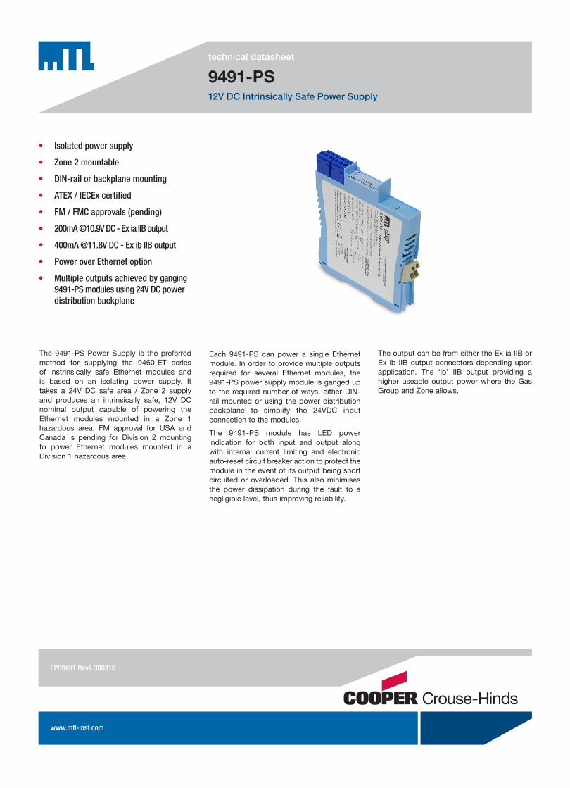
The 9491-PS Power Supply is the preferred method for supplying the 9460-ET series of instrinsically safe Ethernet modules and is based on an isolating power supply. It takes a 24V DC safe area / Zone 2 supply and produces an intrinsically safe, 12V DC nominal output capable of powering the Ethernet modules mounted in a Zone 1 hazardous area. FM approval for USA and Canada is pending for Division 2 mounting to power Ethernet modules mounted in a Division 1 hazardous area.
Each 9491-PS can power a single Ethernet module. In order to provide multiple outputs required for several Ethernet modules, the 9491-PS power supply module is ganged up to the required number of ways, either DIN-rail mounted or using the power distribution backplane to simplify the 24VDC input connection to the modules.
The 9491-PS module has LED power indication for both input and output along with internal current limiting and electronic auto-reset circuit breaker action to protect the module in the event of its output being short circuited or overloaded. This also minimises the power dissipation during the fault to a negligible level, thus improving reliability.
The output can be from either the Ex ia IIB or Ex ib IIB output connectors depending upon application. The ‘ib’ IIB output providing a higher useable output power where the Gas Group and Zone allows.
EPS9491Rev4300310
EUROPE (EMEA): +44 (0)1582 723633 THE AMERICAS: +1 800 835 7075 ASIA-PACIFIC: +65 6 487 7887
[email protected] [email protected] [email protected]
The given data is only intended as a product description and should not be regarded as a legal warranty of proper-ties or guarantee. In the interest of further technical developments, we reserve the right to make design changes.
SPECIFICATIONSee also System Specification
POWER INPUTSeparately poweredInput voltage
24V DC (20–30V)Input current
350mAInput protection
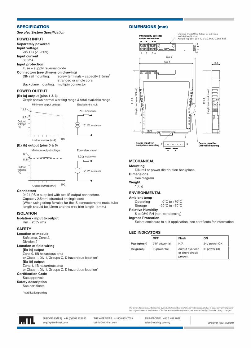
Fuse + supply reversal diodeConnectors (see dimension drawing)
DIN rail mounting: screw terminals – capacity 2.5mm2 stranded or single core
Backplane mounting: multipin connector
POWER OUTPUT[Ex ia] output (pins 1 & 3)
Graph shows normal working range & total available range
����������������������
���������� �����
�
���
�������������
�� ��������
������������������� �� ����� ������������
[Ex ib] output (pins 5 & 6)
����������������������
���������� �����
�
��
�������������
������������
������������������� �� ����� ������������
Connectors9491-PS is supplied with two IS output connectors.Capacity 2.5mm2 stranded or single core(When using crimp ferrules for the IS connectors the metal tube length should be 12mm and the wire trim length 14mm.)
ISOLATIONIsolation - input to output
Um = 253V rms
SAFETYLocation of module
Safe area, Zone 2, Division 2*
Location of field wiring[Ex ia] outputZone 0, IIB hazardous areaor Class 1, Div 1, Groups C, D hazardous location*[Ex ib] outputZone 1, IIB hazardous areaor Class 1, Div 1, Groups C, D hazardous location*
Certification CodeSee approvals
Safety descriptionSee certificate
�������������������������� �������������
�����
�����
����
�����
�����
����
�������������������������
������
����
������
���
���
�
������
����
���
�� �
����
����
��
� � � �
� ��
�
������� �����������������������
��
��
� �
�
������� ���������� �������������
���� ���������������� ������ ������ ����� ���������������� �����������������������������������������������
DIMENSIONS (mm)
MECHANICALMounting
DIN rail or power distribution backplaneDimensions
See diagramWeight
130 g
ENVIRONMENTALAmbient temp
Operating 0°C to +70°CStorage −20°C to +70°C
Relative Humidity5 to 95% RH (non-condensing)
Ingress ProtectionSelect enclosure to suit application, see certificate for information
LED INDICATORSOFF Flash ON
Pwr (green) 24V power fail N/A 24V power OK
IS (green) IS power fail output overload or short circuit present
IS power OK
* certification pending
EPS9491 Rev4 300310
EUROPE (EMEA): +44 (0)1582 723633 THE AMERICAS: +1 800 835 7075 ASIA-PACIFIC: +65 6 487 7887
[email protected] [email protected] [email protected]
The given data is only intended as a product description and should not be regarded as a legal warranty of proper-ties or guarantee. In the interest of further technical developments, we reserve the right to make design changes.
MECHANICALMounting method
DIN-rail DIN-rail types
‘Top hat’, 35 x 7.5 mm to EN 50022 or DIN 46277
ENVIRONMENTALAmbient temp
Operating –20°C to + 70°C(except where stated in individual module specifications)Storage –20°C to + 70°C
Relative Humidity5 to 95% RH (non-condensing)
Ingress ProtectionIP20 to BS EN 60529(Additional protection by means of enclosure)
ELECTRICALEMC compliance
To EN61326:1998 Electrical equipment for measurement, control and laboratory use – EMC requirements
Electrical safetyEN 61010-1
APPLICABLE STANDARDS:• Factory Mutual Research Co., Class No. 3610 for Class I, II, III,
Divisions 1 and 2, Groups A - G hazardous locations (Intrinsically safe circuits).
• Factory Mutual Research Co., Class No. 3611 for Class I, Division 2, Groups A, B, C, D hazardous locations
• EN 60079-0:2006, IEC 60079-0:2004 Electrical apparatus for explosive gas atmospheres – General requirements
• EN 60079-11:2007, IEC 60079-11:2006 Explosive atmospheres -Equipment protection by intrinsic safety "i"
• EN/IEC 60079-15:2005 Electrical apparatus for explosive gas atmospheres - Construction, test and marking of type of protection “n” electrical apparatus
• EN 60079-25:2004, IEC 60079-25:2003 Electrical apparatus for explosive gas atmospheres - Intrinsically safe systems 'i'
• EN 60079-28:2007, IEC 60079-28:2006 Electrical apparatus for explosive gas atmospheres - Part 28: Protection of equipment and transmission systems using optical radiation
• IEC 61241-0:2004 Electrical apparatus for use in the presence of combustible dust. General requirements
• IEC 61241-11:2005 Electrical apparatus for use in the presence of combustible dust. Protection by intrinsic safety “iD”
• EN 50303:2000 Group I, Category M1 equipment intended to remain functional in atmospheres endangered by firedamp and/or coal dust
• EC Directive 94/9/EC (ATEX 100A)
PHYSICAL NETWORKEthernet
9400 SERIESSYSTEM SPECIFICATION
EPS9460 Rev4 300310

EUROPE (EMEA): +44 (0)1582 723633 THE AMERICAS: +1 800 835 7075 ASIA-PACIFIC: +65 6 487 7887
[email protected] [email protected] [email protected]
The given data is only intended as a product description and should not be regarded as a legal warranty of proper-ties or guarantee. In the interest of further technical developments, we reserve the right to make design changes.
APPROVALS
9461-ET, 9465-ET-x -xx, 9466-ETRegion Europe (ATEX) International IECEx USA Canada
Authority SIRA SIRA FM FMC
Standard EN 60079-0:2006,EN 60079-11:2007,IEC 60079-26:2006,IEC 60079-28:2007,EN 50303:2000,IEC 61241-0:2004,IEC 61241-11:2005
IEC 60079-0:2004,IEC 60079-11:2006,IEC 60079-28:2006-08, IEC 61241-0:2004,IEC 61241-1:2005
360036103810
C22.2 No. 61010.1:2004C22.2 No. 157:1992CAN/CSA-E60079-0:2007CAN/CSA-E60079-11:2002
9461-ET &9466-ET Approved for
E II 1GD Ga Ex ia IIC T4 Ex iaD 20 T135°C (Ta = –40˚C to +70˚C)§E I M1Ma Ex ia I (Ta = –40˚C to +70˚C)
Ga Ex ia IIC T4 Ex iaD 20 T135°C Ma Ex ia I (Ta = –40˚C to +70˚C)§
IS/I/1/ABCD/T4 Ta=70°CI/0/AEx ia IIC T4 Ta=70°C
IS/I/1/ABCD/T4 Ta=70°CI/0/AEx ia IIC T4 Ta=70°C
9465-ET-x-xx Approved for
E II 1GD Ga Ex ia IIC T4Ex iaD 20 T135°CGa Ex ia op is IIC T4(Ta = –40˚C to +70˚C)§E I M1Ma Ex ia I Ma Ex ia op is I(Ta = –40˚C to +70˚C)
Ga Ex ia IIC T4 Ga Ex ia op is IIC T4Ex iaD 20 T135°C Ma Ex ia I Ma Ex ia op is I(Ta = –40˚C to +70˚C)§
IS/I/1/ABCD/T4 Ta=70°CI/0/AEx ia IIC T4 Ta=70°C
IS/I/1/ABCD/T4 Ta=70°CI/0/AEx ia IIC T4 Ta=70°C
Cert. no. Sira 07ATEX2064X IECEx SIR 07.0042X 3034995 3034995C
§ (see specification for operating temperature range)
9468-ETRegion Europe (ATEX) International IECEx USA Canada
Authority SIRA SIRA FM FMC
Standard EN 60079-0:2006,EN 60079-11:2007,IEC 60079-26:2006,IEC 61241-0:2004,IEC 61241-11:2005
IEC 60079-0:2004,IEC 60079-11:2006,IEC 60079-26:2006,IEC 61241-0:2004,IEC 61241-11:2005
360036103810
C22.2 No. 61010.1:2004C22.2 No. 157:1992CAN/CSA-E60079-0:2007CAN/CSA-E60079-11:2002
Approved for E II (1) GDE I (M1)(Ga) [Ex ia] IIC[Ex iaD](Ma) [Ex ia] I(Ta = –40˚C to +70˚C)§
(Ga) [Ex ia] IIC[Ex ia D](Ma) [Ex ia] I(Ta = –40°C to +70°C)§
AIS/I/1/ABCD/T4 Ta=70°C[I]/[0]/[AEx ia] IIC T4 Ta=70°C
AIS/I/1/ABCD/T4 Ta=70°C[I]/[0]/[AEx ia] IIC T4 Ta=70°C
Cert. no. Sira 07ATEX2065 IECEx SIR 07.0043 3034995 3034995C
Standard EN 60079-0:2006, IEC 60079-0:2007*,EN 60079-11:2007,EN 60079-15:2005, IEC 60079-26:2006
IEC 60079-0:2004,IEC 60079-11:2006,IEC 60079-15:2005-03
Approved for E II 3 GEx ic (ia) IIC T4 Gc(Ta = –40˚C to +70˚C)§Ex nLc nAc (ia) IIC T4(Ta = –40˚C to +70˚C)§
Ex ic [ia] IIC T4 Gc(Ta = –40°C to +70°C)§Ex nLc nAc [ia] IIC(Ta = –40°C to +70°C)§
Cert. no. Sira 08ATEX4130X IECEx SIR 08.0032X
* (for guidance on the Gc, nLc & nAc marking) § (see specification for operating temperature range)
EPS9460 Rev4 300310
EUROPE (EMEA): +44 (0)1582 723633 THE AMERICAS: +1 800 835 7075 ASIA-PACIFIC: +65 6 487 7887
[email protected] [email protected] [email protected]
The given data is only intended as a product description and should not be regarded as a legal warranty of proper-ties or guarantee. In the interest of further technical developments, we reserve the right to make design changes.
9469-ET Region Europe (ATEX) International IECEx USA Canada
Authority SIRA SIRA FM FMC
Standard EN 60079-0:2006, EN 60079-11:2007,IEC 60079-26:2006, EN 50303:2000,IEC 61241-0:2004,IEC 61241-11:2005
IEC 60079-0:2004,IEC 60079-11:2006,IEC 61241-0:2004,IEC 61241-1:2005
360036103810
C22.2 No. 61010.1:2004C22.2 No. 157:1992CAN/CSA-E60079-0:2007CAN/CSA-E60079-11:2002
Approved for E II 1GD Ga Ex ia IIC T4 Ex iaD 20 T135°C (Ta = –40˚C to +60˚C)§E I M1Ma Ex ia I(Ta = –40˚C to +60˚C)
Ga Ex ia IIC T4 Ex iaD 20 T135°C Ma Ex ia I (Ta = –40˚C to +60˚C)§
IS/I/1/ABCD/T4 Ta=60°CI/0/AEx ia IIC T4 Ta=60°C
IS/I/1/ABCD/T4 Ta=60°CI/0/AEx ia IIC T4 Ta=60°C
Cert. no. Sira 07ATEX2064X IECEx SIR 07.0042X 3034995 3034995C
§ (see specification for operating temperature range)
9491-PS
Region Europe (ATEX) International IECEx USA Canada
Authority SIRA SIRA FM FMC
Standard EN 60079-0:2006,EN 60079-11:2007,IEC 60079-26:2006,IEC 61241-0:2004,IEC 61241-11:2005
IEC 60079-0:2004,IEC 60079-11:2006,IEC 61241-0:2004,IEC 61241-11:2005
Approved for E II (1/2) GD(Ga) [Ex ia] IIB (Gb) [Ex ib] IIB [Ex iaD][Ex ibD]E I (M1/M2)(Ma) [Ex ia] I(Mb) [Ex ib] ITa = 0°C to +70°C
(Ga) [Ex ia] IIB(Gb) [Ex ib] IIB[Ex iaD][Ex ibD](Ma) [Ex ia] I(Mb) [Ex ib] ITa = 0°C to +70°C
Cert. no. Sira 08ATEX2188 IECEx SIR 08.0072 Pending Pending
Standard EN 60079-0:2006,EN 60079-11:2007,EN 60079-15:2005,EN 60079-26:2007,IEC 60079-0:2007*,
IEC 60079-0:2007-10,IEC 60079-11:2006,IEC 60079-15:2005-03,IEC 60079-26:2006
Approved for E II 3G (1)G (2)GEx nAc [ia] [ib] IIB T4(Ta = 0°C to +70°C)
Ex nAc [ia] [ib] IIB T4(Ta = 0°C to +70°C)
Cert. no. Sira 08ATEX4310X IECEx SIR 08.0117X Pending Pending
*(for guidance on marking)
ORDERING INFORMATION
Part No. Description9461-ET IS serial to Ethernet gateway9465-ET-M-ST IS media converter
9465-ET-M-SC IS media converter
9465-ET-S-SC IS media converter
9466-ET IS managed Ethernet switch
9468-ET IS Ethernet isolator
9469-ET IS wireless AP/bridge
Part No. Description
ANT94 Omni-directional antenna - 2.4GHz, 3dBi gain
9491-PS IS power supply
CSL9405-xxx Copper twisted pair FTP Patch Cable (pre-terminated with RJ45 - RJ45 connectors)
-xxx suffix denotes the cable length.
Lengths available from 0.5m – 100m
EPS9460 Rev4 300310