Embed Size (px)
Citation preview

TECHNICAL DATAS /VOLTAGE DROP FORLOW VOLTAGE CABLES
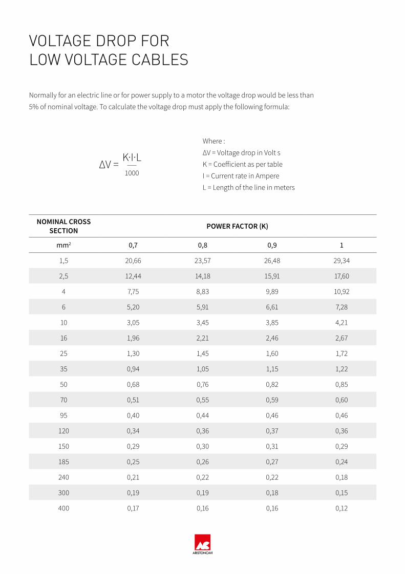
VOLTAGE DROP FORLOW VOLTAGE CABLES
Normally for an electric line or for power supply to a motor the voltage drop would be less than
5% of nominal voltage. To calculate the voltage drop must apply the following formula:
Where :
∆V = Voltage drop in Volt s
K = Coefficient as per table
I = Current rate in Ampere
L = Length of the line in meters
∆V =K·I·L1000
NOMINAL CROSS SECTION POWER FACTOR (K)
mm2 0,7 0,8 0,9 1
1,5 20,66 23,57 26,48 29,34
2,5 12,44 14,18 15,91 17,60
4 7,75 8,83 9,89 10,92
6 5,20 5,91 6,61 7,28
10 3,05 3,45 3,85 4,21
16 1,96 2,21 2,46 2,67
25 1,30 1,45 1,60 1,72
35 0,94 1,05 1,15 1,22
50 0,68 0,76 0,82 0,85
70 0,51 0,55 0,59 0,60
95 0,40 0,44 0,46 0,46
120 0,34 0,36 0,37 0,36
150 0,29 0,30 0,31 0,29
185 0,25 0,26 0,27 0,24
240 0,21 0,22 0,22 0,18
300 0,19 0,19 0,18 0,15
400 0,17 0,16 0,16 0,12

TECHNICAL DATAS /CORRECTION FACTORS

CORRECTION FACTORS (VDE 0298-4)
N° opera-ting cores 5 7 10 14 19 24 40 61
Factor 0,75 0,65 0,55 0,50 0,45 0,40 0,35 0,30
Ambient temp. (C°) 10 15 20 25 30 35 40 45 50 55 60 65 70 75 80 85
Factor 1,15 1,12 1,08 1,04 1 0,96 0,91 0,87 0,82 0,76 0,71 0,65 0,58 0,50 0,41 0,29
CONDUCTORS
SHORT CIRCUIT CURRENT CALCULATIONThe maximum temperature allowed for rubber cables, during short circuit, is 250°C. The maximum thermal short
circuit current allowed, for a timet, can be calculated by the following formulas, valid in adiabatic conditions:
Where :
Icc = Short circuit current (A)
S = Conductor size (mm2)
t = Time period of short circuit (max 5 s)
I c c = 1 4 3 • S t

TECHNICAL DATAS /CURRENT CARRYING CAPACITY,CABLES FORFIXED APPLICATIONMOBILE APPLICATION

For rubber insulated cables EPR:The values shown in the table refer to followin laying and service conditions:
- Conductor service temperature: 90 °C
- Ambient air temperature: 30 °C
- Ground temperature for underground laying: 20 °C
- Ground thermal resistivity: 1° km/W
- Depth of laying: 0,8 m
With different laying conditions, the above values should be multiplied by the respective corrective coefficients.
CURRENT CARRYING CAPACITY,CABLES FOR FIXED APPLICATION
NOMINAL LAYING IN PIPE IN AIR(3 active phases)
LAYING IN FREE AIR(3 active phases)
3 single-core cables
1 three-corecable
3 single-core cables plane laying
1 three-corecable
mm2 A A A A
1.5 20 19.5 24 23
2.5 28 26 33 32
4 37 35 45 42
6 48 44 58 54
10 66 60 80 75
16 88 80 107 100
25 117 105 141 127
35 144 128 176 158
50 175 154 216 192
70 222 194 279 246
95 269 233 342 298
120 312 268 400 346
150 355 300 464 399
185 417 340 533 456
240 490 398 634 538
300 - 455 736 621
400 - - 868 -
500 - - 998 -
630 - - 1151 -

CURRENT CARRYING CAPACITY,CABLES FOR MOBILE APPLICATIONCURRENT CARRYING CAPACITY UP TO 6/10 kV (VDE 0298-4) ambient temperature 30°C
Application
Crosssection
Laying on the floor
Freein air Reeled
1 layer 2 layer 3 layer 4 layer 5 layer 6 layer 7 layer
mm2 A A A A A A A A A1 19 20 15 12 9 8 7 5 4
1,5 24 25 19 15 12 10 9 6 52,5 30 32 24 18 15 13 11 8 74 41 43 33 25 20 17 16 11 96 53 56 42 32 26 22 20 14 12
10 74 78 59 45 36 31 28 20 1616 99 104 79 60 49 42 38 27 2225 131 138 105 80 64 55 50 35 2935 162 170 130 99 79 68 62 44 3650 202 212 162 123 99 85 77 55 4470 250 263 200 153 123 105 95 68 5595 301 316 241 184 147 126 114 81 66
120 352 370 282 215 172 148 134 95 77150 404 424 323 246 198 170 154 109 89185 461 484 369 281 226 194 175 124 101240 528 554 422 322 259 222 201 143 116300 608 638 486 371 298 255 231 164 134
CURRENT CARRYING CAPACITY ABOVE 6/10 kV (VDE 0298-4) ambient temperature 30°C
Application
Crosssection
Laying on the floor Reeled
1 layer 2 layer 3 layer 4 layer 5 layer 6 layer 7 layer
mm2 A A A A A A A A16 105 84 64 51 44 40 28 2325 139 111 85 68 58 53 38 3135 172 138 105 84 72 65 46 38
50 216 173 132 106 91 82 58 48
70 265 212 162 130 111 101 72 5895 319 255 195 156 134 121 86 70
120 371 297 226 182 156 141 100 82150 428 342 261 210 180 163 116 94185 488 390 298 239 205 185 132 107240 574 459 350 281 241 218 155 126300 660 528 403 323 277 251 178 145

TECHNICAL DATAS /ELECTRICAL RESISTANCE

CONDUCTORS
ELECTRICAL RESISTANCE
Electrical W Ohm/km ( according to IEC 60228 - VDE 0295 )
CROSS-SECTION
mm²
FLEXIBLECONDUCTORS,
RESISTANCE AT 20°C
FLEXIBLECONDUCTORS,
RESISTANCE AT 90°C
RIGIDCONDUCTORS,
RESISTANCE AT 20°C
RIGIDCONDUCTORS,
RESISTANCE AT 90°C
Barecopper
Tinned copper
Barecopper
Tinned copper
Barecopper
Tinned copper
Barecopper
Tinned copper
1,5 13,30 13,70 16,93 17,44 12,1 12,2 15,40 15,53
2,5 7,98 8,21 10,16 10,45 7,41 7,56 9,43 9,62
4 4,95 5,09 6,30 6,48 4,61 4,70 5,87 5,98
6 3,30 3,39 4,20 4,32 3,08 3,11 3,92 3,96
10 1,91 1,95 2,43 2,48 1,83 1,84 2,33 2,34
16 1,21 1,24 1,54 1,58 1,15 1,16 1,46 1,48
25 0,78 0,795 0,993 1,012 0,727 0,734 0,925 0,934
35 0,554 0,565 0,705 0,719 0,524 0,529 0,667 0,673
50 0,386 0,393 0,491 0,500 0,387 0,391 0,493 0,498
70 0,272 0,277 0,346 0,353 0,268 0,27 0,341 0,344
95 0,206 0,210 0,262 0,267 0,193 0,195 0,246 0,248
120 0,161 0,164 0,205 0,209 0,153 0,154 0,195 0,196
150 0,129 0,132 0,164 0,168 0,124 0,126 0,158 0,160
185 0,106 0,108 0,135 0,137 0,0991 0,100 0,126 0,127
240 0,0801 0,0817 0,102 0,104 0,0754 0,0762 0,0960 0,0970
300 0,0641 0,0654 0,0816 0,0833 0,0601 0,0607 0,0765 0,0773
400 0,0486 0,0495 0,0619 0,0630 0,0470 0,0475 0,0598 0,0605
500 0,0384 0,0391 0,0489 0,0498 0,0366 0,0369 0,0466 0,0470
630 0,0287 0,0292 0,0365 0,0372 0,0283 0,0286 0,0360 0,0364

TECHNICAL DATAS /GUIDE TO USE

GUIDE TO USE
HANDLING
When handling drums, reasonable precautions should
be taken in consideration in order to avoid damage
to the cable and injury to people. Due regard should
be paid to the mass of the drum, the method and di-
rection of rolling and the method of lifting.
STORAGE
Cable drums should be stored so that the drum flanges do not contact
cable on another drum.
Cables stored at temperatures which are below those recommended for
installation conditions, should not be subject to any mechanical stress
including shocks, impacts, bending and torsions.
If cables are not fully protected (with battens or plastic foils for example),
store should be in a protected area and not weather-beaten. The cable
end should be sealed, in case, to prevent ingress of moisture during
transport and storage.Incorrect
IncorrectIncorrect
Incorrect
Correct
CorrectCorrect
Correct

INSTALLATION & USE
The correct installation method should be done by unwinding the cable
along the machine with standard cable pulling system and rollers. If this
is not possible, because of the site conditions, it’s possible to transfer
the cable directly to the operating drum but avoiding reverse bending
and, if possible, with a distance between the reels at least of 4 meters.
Incorrect
4m
Correct
· A couple of people could walk handling a cylinder bar under the cable
from the drum jacked on up to free end, in this way they will push the
twisting out from the cable. In case of residual twisting repeat the ope-
ration.
It’s necessary to be careful during the transfer of the cable because it
could have a residual torsion from the beginning, before to start its real
application.
In order to remove the initial torsions, if present, we suggest a couple of
solutions:
· Create a spiral with the cable from the drum jacked on and roll it up to
the free end, this operation will remove the twisting
Fix the cable in order to start the operation. If after the first operation
there is still a twisting it’s better to repeat the removal process.

For a large diameter cable it would be better to use rollers to reduce the
friction with the sheath during the change of direction.
RollerSupport Plate
If sheaves are used, it is important to have a flat surface profile, to avoid
unwanted rotations or twisting caused by the continuous clash with the
sides of the sheave. In any case, the width of a cradle or that of a roller,
should be 10-15% larger than the outer cable diameter to allow a cor-
rect running.
If the change of direction cannot be avoided, the minimum distance
with double or S-type directional changer must be bigger than 20xD
(D= overall cable diameter).
≥20x
D
Changing direction during winding or unwinding, is a dangerous ope-
ration: it has to be gradual. The rollers and the shaves must be well po-
sitioned at an adequate distance in order to avoid mechanical stresses
to the cores.CorrectIncorrect
Aristoncavi’s cables are produced with S stranding direction. In this case
we recommend to start winding the cables, on the reeling drum, from
the left side of reel as shown in the pictures:
IncorrectCorrect

CABLE MESH GRIP
Ideal tension relief for cable at feeding point. Safe and simple to handle,
it spreads the forces over a wide surface area to prevent cable damage.
CABLE FEED POINT
Ideal cable guidance at feeding point for centre feed applications.
ROLLER GUIDE
Defined guidance of the cable from reel body to feed point.
CABLE GUIDE
Safe and smooth guidance of the cable for end and centre feed.
TYPES
Monospiral drum (single spire multi layers) ideal to guarantee the
heat dissipation and the control of irregular twisting during unwinding.
The limit could be the cable’s length in relation with the reel’s diameter.
Multispiral drum (multi spires single layer) used in case of long
cable lengths. It is important to ensure that the guide mechanism doe-
sn’t damage the cable during unwinding, for example: avoiding anoma-
lous rub against the surface of the previous spire or irregular twisting. It
is advisable to use maximum two layers to allow the thermal balance.
Cylindric drum (multi spires multi layers random wound) it
is the cheaper reel but it doesn’t guarantee the control over the layers of
cable: the cable could be stacked, for example, on one side of the drum.