Embed Size (px)
Citation preview

FHYCP-B7
4-way Blow CeilingMounted Cassette
(950x950)
technical data
SplitSky Air
air co
nd
ition
ing
system
s

Split - Sky Air
EE
DE0
5-1
/2 •
05/2
005
Prepar
ed in
Belg
ium
by
Goeki
nt
Gra
phic
s
Zandvoordestraat 300
B - 8400 Ostend Belgium
Internet: http://www.daikineurope.com
Specifications are subject to change without prior notice.
ISO14001 assures an effective environmental management system in order to help protecthuman health and the environment from the potentialimpact of our activities, products and services and toassist in maintaining and improving the quality ofthe environment
Daikin Europe N.V. is approved by LRQA for its Quality Management System in accordance with the ISO9001 standard. ISO9001 pertains to quality assurance regarding design, development, manufacturing as well as to services related to the product.
Daikin units comply with the European regulations that guarantee the safety of the product.
Daikin Europe N.V. participates in the Eurovent Certification Programme for Air Conditioners (AC), Liquid Chilling Packages (LCP) and Fan Coil Units (FC); the certified data of certified models are listed in the Eurovent Directory.

TABLE OF CONTENTSFHYCP-B7
1 Features . . . . . . . . . . . . . . . . . . . . . . . . . . . . . . . . . . . . . . . . . . . . . . . . . . . . . . . . . . . . . . . . . . . . . . . . . . . . . . . . . 2
2 Specifications . . . . . . . . . . . . . . . . . . . . . . . . . . . . . . . . . . . . . . . . . . . . . . . . . . . . . . . . . . . . . . . . . . . . . . . 3
Nominal capacity, capacity steps and nominal input
Technical specifications
3 Dimensional drawings . . . . . . . . . . . . . . . . . . . . . . . . . . . . . . . . . . . . . . . . . . . . . . . . . . . . . 8
4 Piping diagrams . . . . . . . . . . . . . . . . . . . . . . . . . . . . . . . . . . . . . . . . . . . . . . . . . . . . . . . . . . . . . . . . . . 9
5 Wiring diagrams . . . . . . . . . . . . . . . . . . . . . . . . . . . . . . . . . . . . . . . . . . . . . . . . . . . . . . . . . . . . . . . . . 10
6 Sound level . . . . . . . . . . . . . . . . . . . . . . . . . . . . . . . . . . . . . . . . . . . . . . . . . . . . . . . . . . . . . . . . . . . . . . . . . . 11
Sound level data
Sound pressure spectrum
7 Air flow patterns & branch duct connections . . . . . . . . . . . . . . . 13
Air flow patterns
Branch duct connections
8 Accessories . . . . . . . . . . . . . . . . . . . . . . . . . . . . . . . . . . . . . . . . . . . . . . . . . . . . . . . . . . . . . . . . . . . . . . . . . . 24
Standard accessories
Optional accessories
9 Control systems . . . . . . . . . . . . . . . . . . . . . . . . . . . . . . . . . . . . . . . . . . . . . . . . . . . . . . . . . . . . . . . . . . 27
10 Center of gravity . . . . . . . . . . . . . . . . . . . . . . . . . . . . . . . . . . . . . . . . . . . . . . . . . . . . . . . . . . . . . . . . 28
11 Safety device settings . . . . . . . . . . . . . . . . . . . . . . . . . . . . . . . . . . . . . . . . . . . . . . . . . . . . . . 28
12 Installation . . . . . . . . . . . . . . . . . . . . . . . . . . . . . . . . . . . . . . . . . . . . . . . . . . . . . . . . . . . . . . . . . . . . . . . . . . . . 29
For capacity tables, please refer to part II: outdoor units
• 4-Way Blow Ceiling Mounted Cassette • R-407C • FHYCP71-125B7
1• Split - Sky Air • Indoor Units
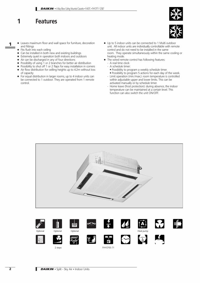
1 Features
+ Leaves maximum floor and wall space for furniture, decorationand fittings
+ Fits flush into each ceiling+ Can be installed in both new and existing buildings+ Extremely quiet in operation both indoors and outdoors+ Air can be discharged in any of four directions+ Possibility of using 1 or 2 branches for better air distribution+ Possibility to shut off 1 or 2 flaps for easy installation in corners+ Air flow distribution for ceilling heights up to 4.2m without loss
of capacity+ For equal distribution in larger rooms, up to 4 indoor units can
be connected to 1 outdoor. They are operated from 1 remotecontrol.
+ Up to 5 indoor units can be connected to 1 Multi outdoorunit. All indoor units are individually controllable with remotecontrol and do not need to be installed in the sameroom. They operate simultaneously within the same cooling orheating mode.
+ The wired remote control has following features:- A real time clock- A schedule timer:Á Possibility to program a weekly schedule timer.Á Possibility to program 5 actions for each day of the week.
- Limit operation (min./max.): room temperature is controlledwithin adjustable upper and lower limits. This can beactivated manually or by schedule timer.
- Home leave (frost protection): during absence, the indoortemperature can be maintained at a certain level. Thisfunction can also switch the unit ON/OFF.
2 1 3 r 8 q x6 5 ) ( 6 4Optional Optional Optional Heat pump
2 steps FHYCP35-71
• 4-Way Blow Ceiling Mounted Cassette • R-407C • FHYCP71-125B7
11
2 • Split - Sky Air • Indoor Units

2 Specifications
NOMINAL CAPACITY and NOMINAL INPUTFor indoor units only:INDOOR UNITS FHYCP35B7V1 FHYCP45B7V1 FHYCP60B7V1NOMINAL INPUT Cooling kW 0.14 0.161
Heating kW 0.14 0.161
For combination indoor + outdoor units (air cooled):INDOOR UNITS FHYCP35B7V1 FHYCP45B7V1 FHYCP60B7V1OUTDOOR UNITS - - -CAPACITY (3) Cooling kW
Twin/triple/double twin application only: RP-L7/B7
NOMINAL INPUT Cooling kWEERENERGY LABEL CoolingANNUAL ENERGYCONSUMPTION
Cooling kWh
For combination indoor + outdoor units (air cooled):INDOOR UNITS FHYCP35B7V1 FHYCP45B7V1 FHYCP60B7V1OUTDOOR UNITS - - -CAPACITY (3) Cooling kW
Twin/triple/double twin application only: RYP-L7
Heating kWNOMINAL INPUT Cooling kW
Heating kWEERCOPENERGY LABEL Cooling
HeatingANNUAL ENERGYCONSUMPTION
Cooling kWh
NOMINAL CAPACITY and NOMINAL INPUTFor indoor units only:INDOOR UNITS FHYCP71B7V1 FHYCP100B7V1 FHYCP125B7V1NOMINAL INPUT Cooling kW 0.161 0.204 0.238
Heating kW 0.161 0.204 0.238
For combination indoor + outdoor units (air cooled):INDOOR UNITS FHYCP71B7V1 FHYCP100B7V1 FHYCP125B7V1OUTDOOR UNITS RP71L7V1/W1-RP71B7T1 RP100L7V1/W1-RP100B7T1 RP125L7W1-RP125B7T1CAPACITY (3) Cooling kW 7.10 10.00 12.20NOMINAL INPUT Cooling kW 2.72/2.66/2.58 3.83/3.56/3.55 4.56/4.58EER 2.61/2.67/2.75 2.67/2.69/2.76 2.69/2.66ENERGY LABEL Cooling D/D/D D/D/D D/DANNUAL ENERGYCONSUMPTION
Cooling kWh 1,360/1,330/1,290 1,875/1,860/1,810 2,265/2,290
For combination indoor + outdoor units (air cooled):INDOOR UNITS FHYCP71B7V1 FHYCP100B7V1 FHYCP125B7V1OUTDOOR UNITS RYP71L7V1/W1 RYP100L7V1/W1 RYP125L7W1CAPACITY (3) Cooling kW 7.10 10.00 12.20
Heating kW 8.00 11.20 14.60NOMINAL INPUT Cooling kW 2.72/2.66 3.83/3.56 4.56
Heating kW 2.85/2.80 3.75/3.66 5.06EER 2.61/2.67 2.61/2.81 2.68COP 2.81/2.86 2.99/3.06 2.89ENERGY LABEL Cooling D/D D/D D
Heating D/D D/D DANNUAL ENERGYCONSUMPTION
Cooling kWh 1,360/1,330 1,915/1,780 2,280
• 4-Way Blow Ceiling Mounted Cassette • R-407C • FHYCP71-125B7
12
3• Split - Sky Air • Indoor Units

TECHNICAL SPECIFICATIONSFor indoor units only:INDOOR UNITS FHYCP35B7V1 FHYCP45B7V1 FHYCP60B7V1DIMENSIONS Unit H mm 230
W mm 840D mm 840
Decoration panel H mm 40W mm 950D mm 950
WEIGHT Unit kg 23Decoration panel kg 5
MATERIAL Unit Galvanised steel plateCOLOUR Decoration panel WhiteSOUND LEVEL Sound pressure
(cooling/heating) (1)high dB(A) 31 33low dB(A) 27 28
Sound power (2) dB(A) 48 50FAN Air flow rate
(cooling/heating)high m3/min 14/14 15/15 18/18low m3/min 10/10 11/11 14/14
Speed steps 2 stepsType Sirocco fanQty x motor output W 1 x 45Drive Direct drive
HEAT EXCHANGER Type Cross fin coilJ7 Hi-XA tubesRows x stages x fin pitch mm 2 x 8 x 1.5Face area m2 0.331
AIR FILTER Resin net (with mold resistant)PIPING CONNECTIONS liquid (flare) mm φ6.4 φ9.5
gas (flare) mm φ12.7 φ15.90drain I.D. mm φ25drain O.D. mm φ32
INSULATION MATERIAL Heat insulation Both liquid and gas pipesSound absorbing insulation Foamed polyethylene
For outdoor unitsonly:
Pair application See chapters RP-L7/B7, RYP-L7
• 4-Way Blow Ceiling Mounted Cassette • R-407C • FHYCP71-125B7
2 Specifications
12
4 • Split - Sky Air • Indoor Units

TECHNICAL SPECIFICATIONSFor indoor units only:INDOOR UNITS FHYCP71B7V1 FHYCP100B7V1 FHYCP125B7V1DIMENSIONS Unit H mm 230 288
W mm 840D mm 840
Decoration panel H mm 40W mm 950D mm 950
WEIGHT Unit kg 23 27Decoration panel kg 5
MATERIAL Unit Galvanised steel plateCOLOUR Decoration panel WhiteSOUND LEVEL Sound pressure
(cooling/heating) (1)high dB(A) 33 37 40low dB(A) 28 32 35
Sound power dB(A) 50 53 56FAN Air flow rate
(cooling/heating)high m3/min 18/18 28/28 31/31low m3/min 14/14 21/21 24/24
Speed steps 2 stepsType Sirocco fanQty x motor output W 1 x 45 1 x 90Drive Direct drive
HEAT EXCHANGER Type Cross fin coilJ7 Hi-XA tubesRows x stages x fin pitch mm 2 x 8 x 1.5 2 x 12 x 1.5Face area m2 0.331 0.497
AIR FILTER Resin net (with mold resistant)PIPING CONNECTIONS liquid (flare) mm φ9.5
gas (flare) mm φ15.90 φ19.10drain I.D. mm φ25drain O.D. mm φ32
INSULATION MATERIAL Heat insulation Both liquid and gas pipesSound absorbing insulation Foamed polyethylene
For outdoor unitsonly:
Pair application See chapters RP-L7/B7, RYP-L7
• 4-Way Blow Ceiling Mounted Cassette • R-407C • FHYCP71-125B7
2 Specifications
12
5• Split - Sky Air • Indoor Units

ELECTRICAL SPECIFICATIONSFor indoor units only: FHYCP35B7V1 FHYCP45B7V1 FHYCP60B7V1CURRENT Nominal running current cooling/heating A See chapters RP-L7/B7, RYP-L7
Max. running current cooling/heating A See chapters RP-L7/B7, RYP-L7
For combination indoor units + outdoor units: FHYCP35B7V1 FHYCP45B7V1 FHYCP60B7V1- - -
CURRENT Nominal running current cooling ATwin/triple/double twin application only: RP-L7/B7Maximum running current cooling A
Starting current cooling A
For combination indoor units + outdoor units: FHYCP35B7V1 FHYCP45B7V1 FHYCP60B7V1- - -
CURRENT Nominal running current cooling/heating ATwin/triple/double twin application only: RYP-L7Maximum running current cooling/heating A
Starting current cooling/heating A
For indoor units only: FHYCP35B7V1 FHYCP45B7V1 FHYCP60B7V1POWER SUPPLY V1 V1 V1NOMINAL DISTRIBUTIONSYSTEM VOLTAGE
Phase 1∼ 1∼ 1∼Frequency Hz 50 50 50Voltage V 230 230 230
NOTES1 Nominal cooling capacities are based on: indoor temperature 27°CDB/19°CWB * outdoor temperature 35°CDB * refrigerant piping length: 7.5m *
level difference: 0m.
2 Nominal heating capacities are based on: indoor temperature: 20°CDB * outdoor temperature: 7°CDB/6°CWB * refrigerant piping length: 7.5m *level difference 0m.
3 Capacities are net, including a deduction for cooling (an addition for heating) for indoor fan motor heat.
4 The sound pressure level is measured at 1.5m distance from the unit. It is a relative value, depending on the distance and acousticenvironment. For measuring conditions: please refer to item 6 of this chapter.
5 The sound power level is an absolute value indicating the ’’power’’ which a sound source generates.
6 Energy label: scale from A (most efficient) to G (less efficient).
7 Annual energy consumption: based on average use of 500 running hours per year at full load (= nominal conditions).
• 4-Way Blow Ceiling Mounted Cassette • R-407C • FHYCP71-125B7
2 Specifications
12
6 • Split - Sky Air • Indoor Units
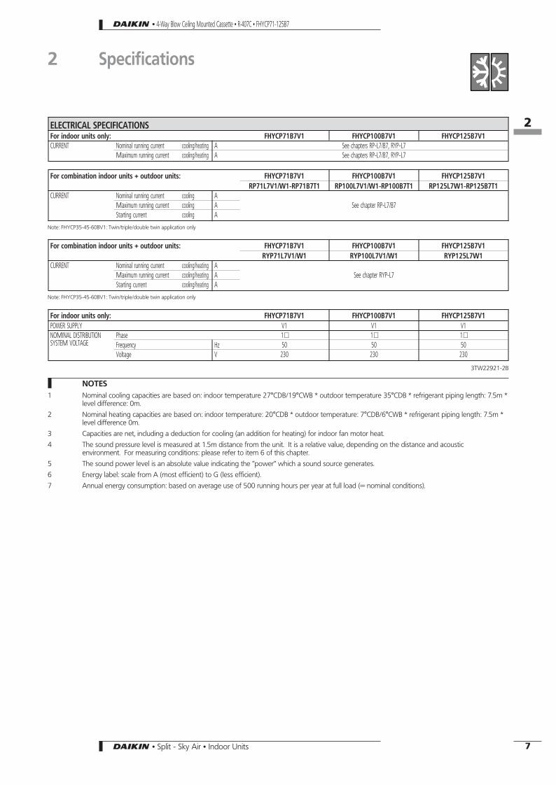
ELECTRICAL SPECIFICATIONSFor indoor units only: FHYCP71B7V1 FHYCP100B7V1 FHYCP125B7V1CURRENT Nominal running current cooling/heating A See chapters RP-L7/B7, RYP-L7
Maximum running current cooling/heating A See chapters RP-L7/B7, RYP-L7
For combination indoor units + outdoor units: FHYCP71B7V1 FHYCP100B7V1 FHYCP125B7V1RP71L7V1/W1-RP71B7T1 RP100L7V1/W1-RP100B7T1 RP125L7W1-RP125B7T1
CURRENT Nominal running current cooling ASee chapter RP-L7/B7Maximum running current cooling A
Starting current cooling A
Note: FHYCP35-45-60BV1: Twin/triple/double twin application only
For combination indoor units + outdoor units: FHYCP71B7V1 FHYCP100B7V1 FHYCP125B7V1RYP71L7V1/W1 RYP100L7V1/W1 RYP125L7W1
CURRENT Nominal running current cooling/heating ASee chapter RYP-L7Maximum running current cooling/heating A
Starting current cooling/heating A
Note: FHYCP35-45-60BV1: Twin/triple/double twin application only
For indoor units only: FHYCP71B7V1 FHYCP100B7V1 FHYCP125B7V1POWER SUPPLY V1 V1 V1NOMINAL DISTRIBUTIONSYSTEM VOLTAGE
Phase 1∼ 1∼ 1∼Frequency Hz 50 50 50Voltage V 230 230 230
3TW22921-2B
NOTES1 Nominal cooling capacities are based on: indoor temperature 27°CDB/19°CWB * outdoor temperature 35°CDB * refrigerant piping length: 7.5m *
level difference: 0m.
2 Nominal heating capacities are based on: indoor temperature: 20°CDB * outdoor temperature: 7°CDB/6°CWB * refrigerant piping length: 7.5m *level difference 0m.
3 Capacities are net, including a deduction for cooling (an addition for heating) for indoor fan motor heat.
4 The sound pressure level is measured at 1.5m distance from the unit. It is a relative value, depending on the distance and acousticenvironment. For measuring conditions: please refer to item 6 of this chapter.
5 The sound power level is an absolute value indicating the ’’power’’ which a sound source generates.
6 Energy label: scale from A (most efficient) to G (less efficient).
7 Annual energy consumption: based on average use of 500 running hours per year at full load (= nominal conditions).
• 4-Way Blow Ceiling Mounted Cassette • R-407C • FHYCP71-125B7
2 Specifications
12
7• Split - Sky Air • Indoor Units

3 Dimensional drawings
FHYCP35-71B7
view A
680 Suspension position
view B
780
(Sus
pens
ion
posit
ion)
860∼
890
(Cei
ling
open
ing)
Note:1. Location of unit’s name plate
Main body: bell mouth inside the suction grille.Decoration panel: panel inner frame inside the suction grille.
2. When installing an optional accessory, refer to the installation drawings.+ For fresh air intake kit - inspection port is necessary+ For high efficiency filter unit - inspection port is not necessary.+ For branch duct chamber - inspection port is not necessary.
1 Liquid pipe connection JA Flare connection2 Gas pipe connectionJB Flare connection3 Drain pipe connection VP25 (O.D.J 32, I.D. J 25)4 Power supply connection5 Transmission wiring connection6 Air discharge grille7 Air suction grille8 Water supply intake9 Corner decoration cover
10 Drain hose O.D.J32
Required installation space
When the discharge grill is closed, the requiredspace is 200mm or more
860∼890 (Ceiling opening)
Adjus
table
(0∼5
50)
Hanging bolt
1000
mm
orm
ore
Requ
ired
serv
ice
spac
e
1500 mm or more
1500 mm or more
1500 mm or more
1500 mm or more
view D
Prepared hole
Branch duct connection
Note 3300 or less
3TW22834-1B
3. In case of using an infrared remote control, this position will be a signalreceiver.Refer to the drawing of infrared remote control in detail
4. When it may exceed 30°C and RH 80% in the ceiling or fresh air isinducted into the ceiling, an additional insulation (Thickness 10mm ormore of glasswool or polyethylene form) is required.
Branch ductconnection
Branch duct connection
Prepared hole
Prepared hole
For fresh air intake kit connection (direct installation type)
view C
Prepared holeModel A BFHYCP35B 6.35 12.70FHYCP45B 6.35 15.90FHYCP60B, FHYCP71B 9.52 15.90
FHYCP100-125B7
view A
680 Suspension position
view B
780
(Sus
pens
ion
posit
ion)
860∼
890
(Cei
ling
open
ing)
Note:1. Location of unit’s name plate
Main body: bell mouth inside the suction grille.Decoration panel: panel inner frame inside the suction grille.
2. When installing an optional accessory, refer to the installation drawings.+ For fresh air intake kit - inspection port is necessary+ For high efficiency filter unit - inspection port is not necessary.+ For branch duct chamber - inspection port is not necessary.
1 Liquid pipe connection JA Flare connection2 Gas pipe connectionJB Flare connection3 Drain pipe connection VP25 (O.D.J 32, I.D. J 25)4 Power supply connection5 Transmission wiring connection6 Air discharge grille7 Air suction grille8 Water supply intake9 Corner decoration cover
10 Drain hose O.D.J32
Required installation space
When the discharge grill is closed, the requiredspace is 200mm or more
860∼890 (Ceiling opening)
Adjus
table
(0∼5
50)
Hanging bolt
1000
mm
orm
ore
Requ
ired
serv
icesp
ace
1500 mm or more
1500 mm or more
1500 mm or more
1500 mm or more
view D
Prepared hole
Branch ductconnection
Note 3300 or less
3TW22874-1A
3. In case of using an infrared remote control, this position will be a signalreceiver.Refer to the drawing of infrared remote control in detail
4. When it may exceed 30°C and RH 80% in the ceiling or fresh air isinducted into the ceiling, an additional insulation (Thickness 10mm ormore of glasswool or polyethylene form) is required.
Branch duct connection
Branch duct connection
Prepared hole
Prepared hole
For fresh air intake kit connection (direct installationtype)
view C
Prepared holeModel A BFHYCP100,125 9.52 19.10
Prepared hole
Branch duct connection
• 4-Way Blow Ceiling Mounted Cassette • R-407C • FHYCP71-125B7
13
8 • Split - Sky Air • Indoor Units
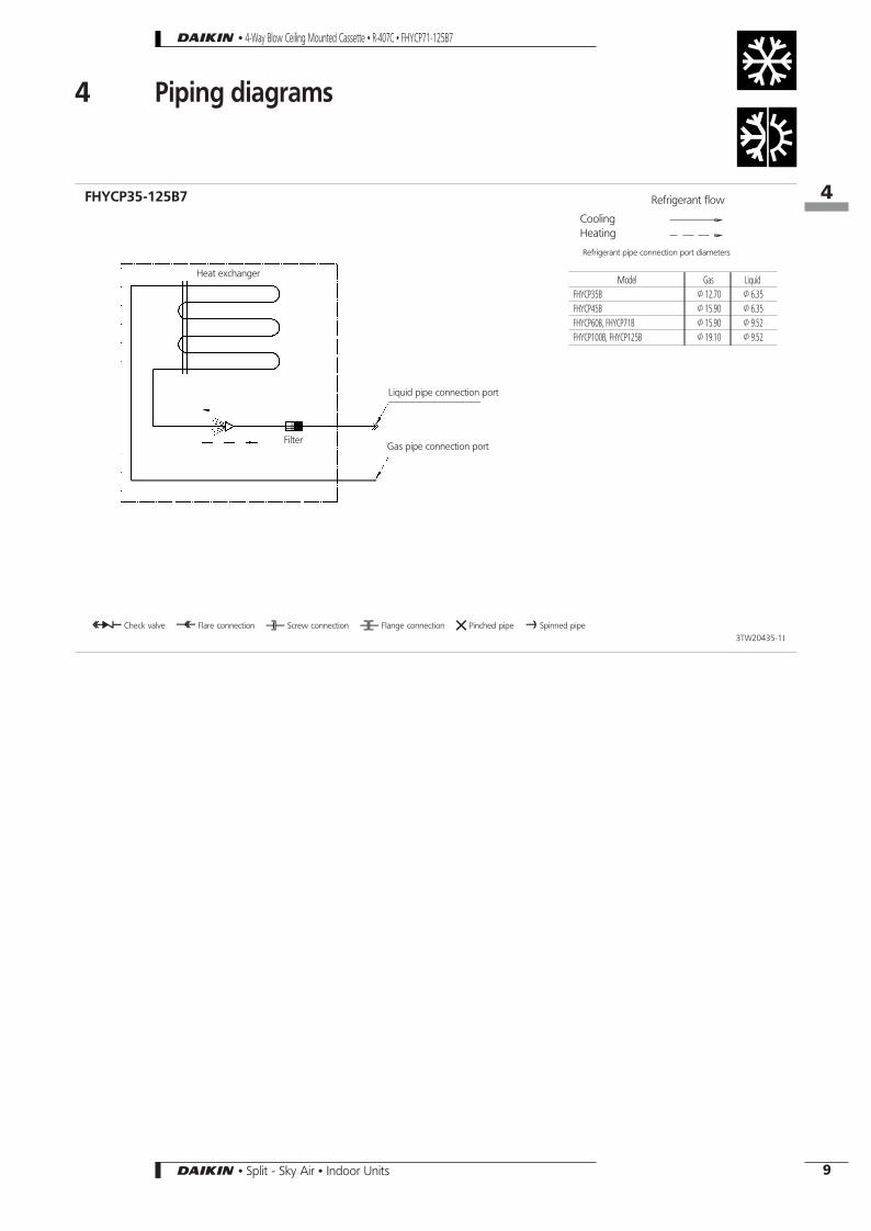
4 Piping diagrams
O Check valve L Flare connection M Screw connection N Flange connection Z Pinched pipe P Spinned pipe
Heat exchanger
Refrigerant flow
CoolingHeating
Liquid pipe connection port
3TW20435-1J
FHYCP35-125B7
Gas pipe connection portFilter
Refrigerant pipe connection port diameters
Model Gas LiquidFHYCP35B J12.70 J6.35FHYCP45B J15.90 J6.35FHYCP60B, FHYCP71B J15.90 J9.52FHYCP100B, FHYCP125B J19.10 J9.52
• 4-Way Blow Ceiling Mounted Cassette • R-407C • FHYCP71-125B7
14
9• Split - Sky Air • Indoor Units

5 Wiring diagrams
3TW22926-1
FHYCP35-125B7
33H Float switchA1P Printed circuit boardC1R Capacitor (M2F)HAP Light emitting diode (service monitor green)HBP Light emitting diode (service monitor green)M1A Motor (swing flap)M2F Motor (indoor fan)M3P Motor (drain pump)Q1F Thermo switch (M2F embedded)R1T Thermistor (air)R2T Thermistor (coil)
RyP Magnetic relay (M3P)SS1 Selector switch (emergency)T1R Transformer (220-240V/22V)X1M Terminal strip (power)X2M Terminal strip (control)= Phase control circuitRC Signal receiver circuit (power)TC Signal transmission circuit (power)Wired remote controlSS1 Selector switch (main/sub)
Receiver / display unit (attached to infrared remote control)A2P,A3P Printed circuit boardBS Push button (on/off)H1P Light emitting diode (on-red)H2P Light emitting diode (timer-green)H3P Light emitting diode (filter sign-red)H4P Light emitting diode (defrost-orange)SS1 Selector switch (main/sub)SS2 Selector switch (wireless address set)
Indoor
Outdoor
Wired remotecontrol
Terminals for operation indicator
Note 3Receiver / display unit
Adapter forwiring
Fan operationcompressor operation
Notes
1. Use copper conductors only.2. When using the central remote control, see manual for
connection to the unit.3. X24A is connected when the remote control kit is used.4. The infrared remote control model varies according to
the combination system. See technical data andcatalogues before connecting.
g Field wiring D TerminalF : Connectorh : Wire clampb : Protective earth (screw)ColoursBLK: Black / WHT: White / RED: Red / YLW: Yellow
Adapter for wiringRyC,RyF Magnetic relayConnector for optional partsX30A Connector (interface adapter for sky air series)X33A Connector (adapter for wiring)X35A Connector (group control adapter)
Switch box
Simultaneous operation system
Infrared remotecontrol
Out
door
unit
Mas
ter
Slav
eRemote On/Off
Forced off
Norm. emerg.
4D010992A
V1, ModelPower supply1∼50Hz220V-240V
Fuse
Main switch Main switch
Fuse Fuse
NOTES1 Line voltage wiring
Control circuit wiring2 All wiring, components and materials to be produced on the site must comply with the applicable local and national codes.3 Use copper conductors only.4 See wiring diagrams for details.5 Install fuse and mainswitch for safety.6 All field wiring and components must be provided by a licensed electrician.7 The unit shall be grounded in compilance with the applicable local and national codes.8 Wiring shown are general points-of-connection guides only and are not intended for or to include all details for a specific
installation.9 Never share a common power supply with other equipment.
H05VV−U4G
T1, ModelPower supply1∼50Hz230V
W1, ModelPower supply3N∼50Hz380V-415V
Main switch
• 4-Way Blow Ceiling Mounted Cassette • R-407C • FHYCP71-125B7
15
10 • Split - Sky Air • Indoor Units

6 Sound level6-1 Sound level data
Heat pump
Model
Sound pressure level
Sound power level (H)(cooling/heating)
230V
Measuring location50Hz
H (cooling/heating) L (cooling/heating)
FHYCP35B7 31/31 27/27 48/48
FHYCP45B7 31/31 27/27 48/48
FHYCP60B7 33/33 28/28 50/50
FHYCP71B7 33/33 28/28 50/50
FHYCP100B7 37/37 32/32 53/53
FHYCP125B7 40/40 35/35 56/56
Microphone
Unit
• 4-Way Blow Ceiling Mounted Cassette • R-407C • FHYCP71-125B7
16
6-1
11• Split - Sky Air • Indoor Units

6 Sound levels6-2 Sound pressure spectrum
FHYCP100 FHYCP125
Octave band center frequency (Hz) Octave band center frequency (Hz)
Soun
dpr
essu
rele
vel(
dB)
Soun
dpr
essu
rele
vel(
dB)
Legend
High speed
Low speed
NOTES1 Data is valid at free field condition and nominal operation
condition (230V, air discharge in 4 directions).
2 The operation noise differs with the operation and ambientconditions.
3 dB(A) = A-weighted sound pressure level (A-scale according toIEC)
4 Reference acoustic pressure 0dB = 20Pa
Soun
dpr
essu
rele
vel(
dB)
Soun
dpr
essu
rele
vel(
dB)
FHYCP35-45 FHYCP60-71
Octave band center frequency (Hz) Octave band center frequency (Hz)3TW22837-1 3TW22857-1
3TW22877-1 3TW22887-1
• 4-Way Blow Ceiling Mounted Cassette • R-407C • FHYCP71-125B7
16
6-2
12 • Split - Sky Air • Indoor Units

7 Air flow patterns & branch duct connections7-1 Air flow patterns
FHYCP35B7
Heating - air velocity distribution
4-way discharge, air flow direction: down
FHYCP35B7
Heating - air temperature distribution
4-way discharge, air flow direction: down
4D024116
• 4-Way Blow Ceiling Mounted Cassette • R-407C • FHYCP71-125B7
17
7-1
13• Split - Sky Air • Indoor Units

FHYCP45B7
Heating - air velocity distribution
4-way discharge, air flow direction: down
FHYCP45B7
Heating - air temperature distribution
4-way discharge, air flow direction: down
4D024117
• 4-Way Blow Ceiling Mounted Cassette • R-407C • FHYCP71-125B7
7 Air flow patterns & branch duct connections7-1 Air flow patterns
17
7-1
14 • Split - Sky Air • Indoor Units

FHYCP60-71B7
Heating - air velocity distribution
4-way discharge, air flow direction: down
FHYCP60-71B7
Heating - air temperature distribution
4-way discharge, air flow direction: down
4D024118
• 4-Way Blow Ceiling Mounted Cassette • R-407C • FHYCP71-125B7
7 Air flow patterns & branch duct connections7-1 Air flow patterns
17
7-1
15• Split - Sky Air • Indoor Units

FHYCP100B7
Heating - air velocity distribution
4-way discharge, air flow direction: down
FHYCP100B7
Heating - air temperature distribution
4-way discharge, air flow direction: down
4D024119
• 4-Way Blow Ceiling Mounted Cassette • R-407C • FHYCP71-125B7
7 Air flow patterns & branch duct connections7-1 Air flow patterns
17
7-1
16 • Split - Sky Air • Indoor Units

FHYCP125B7
Heating - air velocity distribution
4-way discharge, air flow direction: down
FHYCP125B7
Heating - air temperature distribution
4-way discharge, air flow direction: down
4D024120
• 4-Way Blow Ceiling Mounted Cassette • R-407C • FHYCP71-125B7
7 Air flow patterns & branch duct connections7-1 Air flow patterns
17
7-1
17• Split - Sky Air • Indoor Units

7 Air flow patterns & branch duct connections7-2 Branch duct connections
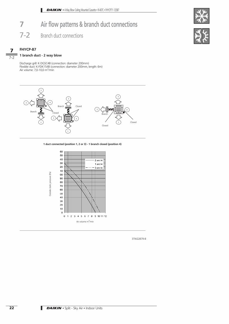
FHYCP-B7
1 branch duct - 3 way blow
Discharge grill: K-DGSC4B (connection: diameter 150mm)Flexible duct K-FDK154B (connection: diameter 150mm, length: 4m)Air volume: 1,5-2,0 m3/min
Closed
Branch ductPipe connections
Branch
Closed
Closed
BranchClosed
Branch
1 branch duct connected (position 1) 1 branch duct connected (position 3) 1 branch duct connected (position 2 or 4)
Air volume m3/min Air volume m3/min Air volume m3/min
Out
side
stat
icpr
essu
re(P
a)
Out
side
stat
icpr
essu
re(P
a)
Out
side
stat
icpr
essu
re(P
a)
3TW22839-7
• 4-Way Blow Ceiling Mounted Cassette • R-407C • FHYCP71-125B7
17
7-2
18 • Split - Sky Air • Indoor Units

FHYCP-B7
1 branch duct - 2 way blow
Discharge grill: K-DGSC4B (connection: diameter 150mm)Flexible duct K-FDK154B (connection: diameter 150mm, length: 4m)Air volume: 2,0-3,0 m3/min
Branch Closed
Branch
Branch
Closed
1 duct connected (position 1 or 3) -1 branch closed (position 4)
1 duct connected (position 2) -1 branch closed (position 4)
Air volume m3/min Air volume m3/min
Out
side
stat
icpr
essu
re(P
a)
Out
side
stat
icpr
essu
re(P
a)
3TW22839-8
Closed
Closed
• 4-Way Blow Ceiling Mounted Cassette • R-407C • FHYCP71-125B7
7 Air flow patterns & branch duct connections7-2 Branch duct connections
17
7-2
19• Split - Sky Air • Indoor Units

FHYCP-B7
2 branch duct - 2 way blow
Discharge grill: K-DGSC4B (connection: diameter 150mm)Flexible duct K-FDK154B (connection: diameter 150mm, length: 4m)Air volume: 4,0-5,0 m3/min
Branch
Branch
Closed
BranchClosed
Closed
Branch
Closed
Branch
2 branch ducts connected (position 1 and 4) 2 branch ducts connected (position 3 and 4) 2 branch ducts connected (position 2 and 4)
Air volume m3/min Air volume m3/min Air volume m3/min
Out
side
stat
icpr
essu
re(P
a)
Out
side
stat
icpr
essu
re(P
a)
Out
side
stat
icpr
essu
re(P
a)
3TW22839-9
Branch
• 4-Way Blow Ceiling Mounted Cassette • R-407C • FHYCP71-125B7
7 Air flow patterns & branch duct connections7-2 Branch duct connections
17
7-2
20 • Split - Sky Air • Indoor Units

FHYCP-B7
1 branch duct - 3 way blow
Discharge grill: K-DGSC4B (connection: diameter 200mm)Flexible duct: K-FDK154B (connection: diameter 200mm, length: 6m)Air volume: 5,0-7,0 m3/min
ClosedBranch duct Pipe connections
Branch
Closed
ClosedBranch
Closed
Branch
1 branch duct connected (position 1) 1 branch duct connected (position 3) 1 branch duct connected (position 2 or 4)
Air volume m3/min Air volume m3/min Air volume m3/min
Out
side
stat
icpr
essu
re(P
a)
Out
side
stat
icpr
essu
re(P
a)
Out
side
stat
icpr
essu
re(P
a)
3TW22879-7
• 4-Way Blow Ceiling Mounted Cassette • R-407C • FHYCP71-125B7
7 Air flow patterns & branch duct connections7-2 Branch duct connections
17
7-2
21• Split - Sky Air • Indoor Units
FHYCP-B7
1 branch duct - 2 way blow
Discharge grill: K-DGSC4B (connection: diameter 200mm)Flexible duct: K-FDK154B (connection: diameter 200mm, length: 6m)Air volume: 7,0-10,0 m3/min
Branch Closed Branch
Closed
1 duct connected (position 1, 2 or 3) - 1 branch closed (position 4)
Air volume m3/min
Out
side
stat
icpr
essu
re(P
a)
3TW22879-8
Closed
ClosedBranch
• 4-Way Blow Ceiling Mounted Cassette • R-407C • FHYCP71-125B7
7 Air flow patterns & branch duct connections7-2 Branch duct connections
17
7-2
22 • Split - Sky Air • Indoor Units

FHYCP-B7
2 branch duct - 2 way blow
Discharge grill: K-DGSC4B (connection: diameter 200mm)Flexible duct: K-FDK154B (connection: diameter 200mm, length: 6m)Air volume: 9,0-11,0 m3/min
Branch Closed
Branch
ClosedClosed
Branch
Closed
Branch
2 branch ducts connected (4 and 1 or 4 and 2 or 4 and 3)
Air volume m3/min
Out
side
stat
icpr
essu
re(P
a)
3TW22879-9
Branch
Branch
• 4-Way Blow Ceiling Mounted Cassette • R-407C • FHYCP71-125B7
7 Air flow patterns & branch duct connections7-2 Branch duct connections
17
7-2
23• Split - Sky Air • Indoor Units

8 Accessories8-1 Standard accessories
Check if the following accessories are included with your unit.
Clamp1 pc.
Also used as packing material
Paper pattern for installation1 pc.
Drain hose1 pc.
Screws M5For paper pattern for installation
4 pcs.Washer for hanging bracket
8 pcs.Sealing2 pcs.
Insulation for fitting1 of each
For gas pipe For liquid pipe
Other: installation manual, operationmanual
• 4-Way Blow Ceiling Mounted Cassette • R-407C • FHYCP71-125B7
18
8-1
24 • Split - Sky Air • Indoor Units

8 Accessories8-2 Optional accessories
Options
Item Model FHYCP35 FHYCP45 FHYCP60 FHYCP71 FHYCP100 FHYCP125
Decoration panel BYC125K7W1B
Filter related High efficiency filter 65% Colorimetric method KAFJ556K80 KAFJ556K160
High efficiency filter 90% Colorimetric method KAFJ557K80 KAFJ557K160
Replacement high effiency filter 65% Colorimetric method KAFJ552K80 KAFJ552K160
Replacement high effiency filter 90% Colorimetric method KAFJ553K80 KAFJ553K160
Filter chamber KDDFJ55K160
Replacement long-life filter Non-woven type KAFJ551K160
Ultra-long life filter KAFJ55K160
Replacement ultra long-life filter KAFJ55K160H
Fresh air intake kit Chamber type Without T-shape and fan KDDJ55B160
With T-shape, and fan KDDJ55B160F
With T-shape, without fan KDDJ55B16OK
Direct installation type KDDJ55X160
Sealing member of air discharge outlet KDBHJ55B160
Panel spacer KDBJ55K160W
Branch duct chamber KDJ55B80 KDJ55B160
Chamber connection kit KKSJ55K160
Control systems
Item Model FHYCP35 FHYCP45 FHYCP60 FHYCP71 FHYCP100 FHYCP125
Remote control Infrared Heat pump BRC7C512W
Cooling only BRC7C513W
Wired BRC1D527
Wiring adapter (hour meter) *1 EKRP1B2
Wiring adaptor for electrical appendices *2 KRP1B57
Wiring adaptor for electrical appendices *2 KRP4A53
Remote sensor KRCS01-1
Installation box for adapter PCB KRP1C98
Central remote control DCS302C51
Electrical box with earth terminal (3 blocks) KJB311A
Unified ON/OFF control DCS301B51
Electrical box with earth terminal (2 blocks) KJB212A
Noise filter (for electromagnetic interface use only) KEK26-1
Schedule timer DST301B51
Interface adapter for Sky Air series DTA102A52
Remote ON/OFF, forced OFF EKRORO
*1 Possibility to connect an hour meter. This part should not be installed inside the equipment.*2 Installation box for adapter PCB (KRP1C93) is necessary. 3TW22839-6B
• 4-Way Blow Ceiling Mounted Cassette • R-407C • FHYCP71-125B7
18
8-2
25• Split - Sky Air • Indoor Units

Specifications EKRORO
Wire specifications
Connector (White) White
connect to indoor PCB (X40A) connect to on/off switch
AWG24 0.22mm2 White
* Input ’ON’ = closed contact.
Forced off On/off operation
Input ’on’ stops operation + disables control Input off→on: starts operation, remote control is still enabled.
Input ’off’ enables control Input on→off: stops operation, remote control is still enabled.
Selection of ’FORCED OFF’ and ’ON/OFF’ operation
Setting Mode NO First code NO Second code NO
Forced off 12 (22) 1 01
On/off operation 02
Operating method
Switch
Remote control
Standard setting:’forced off’
Alternativesetting: ’on/off’
ON*
OFF
ON
OFF
ON
OFF
ON
OFF
Uni
tIn
put
4TW23941-1
• 4-Way Blow Ceiling Mounted Cassette • R-407C • FHYCP71-125B7
8 Accessories8-2 Optional accessories
18
8-2
26 • Split - Sky Air • Indoor Units

9 Control systems9-1 Wired remote control
6.5 x 9 (Round end slit)
Cover open
Cover closed
5 x 7 (Round end slit) HoleJ5
5 x 10 (Round end slit)
3TW23651-2
BRC1D527
• 4-Way Blow Ceiling Mounted Cassette • R-407C • FHYCP71-125B7
19
9-1
27• Split - Sky Air • Indoor Units

10 Center of gravity
Model A B
FHYCP35-71B7 230 90
FHYCP100-125B7 288 120
4TW22839-2A
11 Safety device settings
Model Safety devices 35 45 60 71 100 125
FHYCP-B7Fan motor thermal protector (°C) OFF: 130±5
ON: 80±20OFF: 130±5ON: 80±20
OFF: 130±5ON: 80±20
OFF: 130±5ON: 80±20
OFF: 130±5ON: 80±20
OFF: 130±5ON: 80±20
Drain pump fuse (°C) 145 145 145 145 145 145
3TW22831-3A
• 4-Way Blow Ceiling Mounted Cassette • R-407C • FHYCP71-125B7
110
28 • Split - Sky Air • Indoor Units

12 Installation
FHYCP-B7
Number Description
1 Indoor unit
2 Outdoor unit
3 Wired remote control
4 Inlet air
5 Discharged air
6 Refrigerant piping, connection electric wire
7 Drain pipe
8Ground wireWire to ground from the outdoor unit to preventelectrical shocks.
9 Air filter
• 4-Way Blow Ceiling Mounted Cassette • R-407C • FHYCP71-125B7
112
29• Split - Sky Air • Indoor Units