Embed Size (px)
Citation preview
Technical Data Sheet
RF/Microwave Signal GeneratorsMG37020AFast Switching Microwave Signal Generator, 100 µsec Switching Speed, 10 MHz to 20 GHz
IntroductionThe MG37020A Fast Switching Microwave Signal Generator is the “ideal microwave signal generator” for applica-tions where fast frequency switching speed is a critical parameter, including data intensive applications, high throughput manufacturing test, and signal simulation. The MG37020A Fast Switching Microwave Signal Generator provides fast switching speed along with high output power, low phase noise, spectral purity, high performance pulse modulation, size, upgradeability, reliability and service. Our signal generators are configurable for a broad range of applications from R&D to manufacturing and depot repair. Anritsu provides you a total solution including proven reliability and standard 3 year warranty plus pre- and post-sale support that is the best in the industry.
2
SpecificationsThe specifications in the following pages describe the warranted perfor-mance of the generator for 25 ºC ± 10 ºC. Typical specifications describe expected, but not warranted, performance based on sample testing.
Frequency CoverageModel/Option 4 Frequency Coverage Output Type
MG37022A 2 to 20 GHz K(f)
Option 4 10 MHz to 2.2 GHz K(f)
Option 4: Frequency extension down to 10 MHz. Option 4 uses a digital down-converter (DDC) with successive divide-by-two circuitry. It offers reduced SSB phase noise compared to heterodyne down-converters.
CW ModeAccuracy: Same as internal or external 10 MHz time base.Internal Time Base Stability:
With aging: < 2 x 10⁻⁸/day With temperature: < 2 x 10⁻⁸/deg C over 0 ºC to 50 ºC
Internal Time Base Calibration:
The internal time base can be calibrated via the System Cal Menu to match an external reference (10 MHz ±50 Hz).Resolution: 0.001 HzExternal 10 MHz Reference Input:
Accepts external 10 MHz ± 50 Hz (typical), 0 to +20 dBm time base signal. Automatically detects and switches to the external reference(whenapplied).RearpanelBNC,50Ωimpedance.Selectable bandwidth for best phase noise immunity or best phase tracking performance.
10 MHz Reference Output:
>–5dBm50Ω.ACcoupled. RearpanelBNC:50Ωimpedance,DCcoupled,TTLcompatible
Electronic Frequency Control (EFC) Input:
–5V to +5V input range. 2.5 x 10⁻⁶ Hz/V sensitivity (typical). <250 Hz modulation bandwidth. Rear Panel BNC: high impedance
Phase-Locked Step ModeSweep Width: Independently selected, 0.001 Hz to full range. Every frequency step in sweep range is phase-locked.Accuracy: Same as internal or external 10 MHz time base.Resolution (Minimum Step Size): 0.001 HzSteps: User-selectable number of steps or the step size.Number of Steps: Variable from 1 to 10,000Step Size: 0.001 Hz to the full frequency range of the instrument. (If the step size does not divide into the selected frequency range, the last step is truncated.)Dwell Time Per Step: Variable from 50 µs to 30 seconds
List Sweep ModeUnder remote control or via the front panel, up to 4 tables of 3 table types with 10,001 non-sequential frequency/power sets can be stored and then addressed as a phase-locked step sweep. One table type of 10,001 points is stored in volatile memory, all other tables are stored in non-volatile memory.
Sweep TriggeringSweep triggering is provided for Step Frequency Sweep, andListFrequencySweep.Auto: Triggers sweep automatically.External: Triggers a sweep on the low to high transition of an external TTLsignal.AUXI/OconnectororBNC,rearpanel.Single: Triggers, aborts, and resets a single sweep. Reset sweep may be selected to be at the top or bottom of the sweep.Manual (List Sweep):GPIBGETorexternalTTLtriggerwillsteptonextindex between start/stop indices.
Ultra-Stable Phase Tracking (Option 36)Option 36 adds the rear panel BNC connectors and internal connec-tions required to provide ultra stable phase tracking between multiple MG37020A synthesizers. Up to four instruments may be inter-connected.100 MHz Reference Output: Provides the reference signal to drive up to three other MG37020A. All must have Option 36. This signal is only intended for use with other Option 36 instruments.100 MHz Reference Input: Accepts the 100 MHz reference signal from another MG37020A with Option 36. This input is only intended for use with other Option 36 instruments.Phase Drift: < ± 1º over 100 seconds (typical), after 24 hours warm-up time.
3
GeneralStored Setups: Stores front panel settings on the hard disk drive. The number of stored settings is limited only by the available space on the hard disk drive. A system menu allows saving and recalling of instrument setups. Whenever the instrument is turned on, control settings come on at the same functions and values existing when the instrument was turned off.Self-Test: Instrument self-test is performed when Self-Test menu screen is selected. If an error is detected, an error message is shown in a window on the display identifying the probable cause and remedy.Parameter Entry: Instrument-controlled parameters can be entered in multiple ways: keypad, rotary data knob, the < and > touch pads of the cursor-control key, directly on the touch screen, with an external USB keyboard, or with an external USB mouse. The keypad or keyboard is used to enter ndefense parameter values; the rotary data knob and the cursor-control key are used to edit existing parameter values. The s and t touch pads of the cursor-control key move the cursor left and right one digit under the open parameter. The rotary data knob or the s and t touch pads will increment or decrement the digit position over the cur-sor. Controlled parameters are frequency, power level, sweep time, dwell time, and number of steps. Keypad entries are terminated by pressing the appropriate menu screen. Edits are terminated by exiting the edit menu.Preset: Returns all instrument parameters to predefined default states or values. Any pending remote control command is aborted.Warm Up Time:
From Standby: 30 minutes. From Cold Start (0 deg C): 120 hours to achieve specified frequency stability with aging. Instruments disconnected from AC line power for more than 72 hours require 30 days to return to specified frequency stability with aging.
Power: 85-264 Vac, 48-440 Hz, 250 VA maximumStandby: With ac line power connected, unit is placed in standby when front panel power switch is released from the OPERATE position.Weight: 20 kg maximumDimensions: 133 H x 429 W x 450 D mmWarranty: 3 years from ship date
Remote OperationAll instrument functions, settings, and operating modes (except for power on/standby) are controllable using commands sent fromanexternalcomputerviatheEthernetLAN,USBortheGPIB (IEEE-488 interface bus).GPIB Address: Selectable from a system menu IEEE-488 Interface Function Subset:
Source Handshake: SH1 Acceptor Handshake: AH1 Talker: T6 Listener:L4 Service Request: SR1 Remote/Local:RL1 Parallel Poll: PP1 Device Clear: DC1 Device Trigger: DT1 Controller Capability: C0 Tri-State Driver: E2
GPIB Status Annunciators: When the instrument is operating in Remote, the GPIB status annunciators (listed below) will appear in awindowonthefrontpanelLCD.Remote: Operating on the GPIB (all instrument front panel keys exceptfortheRETURNTOLOCALandtheDISPLAYUPDATES soft-keys will be ignored).LLO (Local Lockout):DisablestheRETURNTOLOCALsoft-key.Instrument can be placed in local mode only via GPIB or by cycling line power.
Environmental (MIL-PRF-28800F, class 3)Storage Temperature Range: –40 °C to +75 °COperating Temperature Range: 0 ºC to +50 °CRelative Humidity: 5% to 95% at 40 °CAltitude: 4,600 meters, 43.9 cm HgEMI: Meets the emission and immunity requirements of EN61326: 1998
EN55011: 1991/CISPR-11:1990 Group 1 Class A EN61000-4-2: 1995 – 4 kV CD, 8 kV AD EN61000-4-3: 1997 – 3 V/m EN61000-4-4:1995–0.5kVSL,1kVPL EN61000-4-5:1995–1kV–2kVL-E EN61000-4-6: 1996 EN61000-4-11: 1994
Vibration:
Random, 5-500 Hz, 0.015-0.0039g2/Hz PSD Sinusoidal, 5-55 Hz, 0.33 mm displacementSafety Directive: EN 61010-1: 1993 + A1: 92 + A2: 95
4
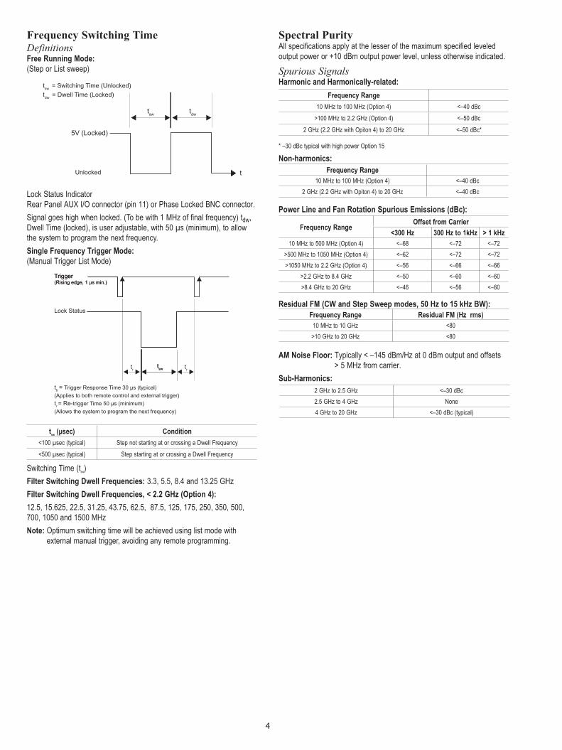
Frequency Switching TimeDefinitionsFree Running Mode: (SteporListsweep)
LockStatusIndicator RearPanelAUXI/Oconnector(pin11)orPhaseLockedBNCconnector.Signal goes high when locked. (To be with 1 MHz of final frequency) tdw, Dwell Time (locked), is user adjustable, with 50 µs (minimum), to allow the system to program the next frequency.Single Frequency Trigger Mode: (ManualTriggerListMode)
Switching Time (tsw)Filter Switching Dwell Frequencies: 3.3, 5.5, 8.4 and 13.25 GHzFilter Switching Dwell Frequencies, < 2.2 GHz (Option 4):
12.5, 15.625, 22.5, 31.25, 43.75, 62.5, 87.5, 125, 175, 250, 350, 500, 700, 1050 and 1500 MHzNote: Optimum switching time will be achieved using list mode with
external manual trigger, avoiding any remote programming.
Spectral PurityAll specifications apply at the lesser of the maximum specified leveled output power or +10 dBm output power level, unless otherwise indicated.
Spurious SignalsHarmonic and Harmonically-related:
* –30 dBc typical with high power Option 15
Non-harmonics:
Power Line and Fan Rotation Spurious Emissions (dBc):
Residual FM (CW and Step Sweep modes, 50 Hz to 15 kHz BW):
AM Noise Floor: Typically < –145 dBm/Hz at 0 dBm output and offsets > 5 MHz from carrier.
Sub-Harmonics:2 GHz to 2.5 GHz <–30 dBc2.5 GHz to 4 GHz None4 GHz to 20 GHz <–30 dBc (typical)
Frequency Range Residual FM (Hz rms)10 MHz to 10 GHz <80>10 GHz to 20 GHz <80
Frequency RangeOffset from Carrier
<300 Hz 300 Hz to 1kHz > 1 kHz10 MHz to 500 MHz (Option 4) <–68 <–72 <–72
>500 MHz to 1050 MHz (Option 4) <–62 <–72 <–72>1050 MHz to 2.2 GHz (Option 4) <–56 <–66 <–66
>2.2 GHz to 8.4 GHz <–50 <–60 <–60>8.4 GHz to 20 GHz <–46 <–56 <–60
ttr = Trigger Response Time 30 µs (typical)
(Applies to both remote control and external trigger)
tr = Re-trigger Time 50 µs (minimum)
(Allows the system to program the next frequency)
tsw
Trigger(Rising edge, 1 µs min.)
Lock Status
tr
tsw
Trigger(Rising edge, 1 µs min.)
tr
tsw
tsw
= Switching Time (Unlocked)
tdw
= Dwell Time (Locked)
tdw
t
5V (Locked)
Unlocked
Frequency Range
10 MHz to 100 MHz (Option 4) <–40 dBc
>100 MHz to 2.2 GHz (Option 4) <–50 dBc
2 GHz (2.2 GHz with Opiton 4) to 20 GHz <–50 dBc*
Frequency Range10 MHz to 100 MHz (Option 4) <–40 dBc
2 GHz (2.2 GHz with Opiton 4) to 20 GHz <–40 dBc
tsw (µsec) Condition
<100 µsec (typical) Step not starting at or crossing a Dwell Frequency
<500 µsec (typical) Step starting at or crossing a Dwell Frequency

5
Single-Sideband Phase Noise *Single-Sideband Phase Noise (dBc/Hz): (typical)
* Phase Noise is specified and guaranteed only with internal reference. In external reference mode, the phase noise of the external supplied reference and the external reference bandwidth will dictate the instrument phase noise performance. Phase noise is not degraded when adding the high power Option 15.
Typical MG37020A single sideband phase noise at 10 GHz carrier.
-140
-130
-120
-110
-100
-90
-80
-70
-60
-50
-40
10 100 1000 10000 100000 1000000 10000000
MG37020A SSB Phase Noise
Specification
Measured
Phase Noise (f)dBc/Hz
Frequency RangeOffset from carrier
10 Hz 100 Hz 1 kHz 10 kHz 100 kHz 1 MHz 10 MHz to 15.625 MHz (Option 4) –101 (–115) –126 (–132) –139 (–143) –142 (–145) –142 (–145) –145 (–148) >15.625 MHz to 31.25 MHz (Option 4) –95 (–106) –121 (–127) –134 (–142) –139 (–145) –139 (–145) –145 (–148) >31.25 MHz to 62.5 MHz (Option 4) –89 (–96) –116 (–122) –129 (–140) –135 (–145) –137 (–145) –142 (–150) >62.5 MHz to 125 MHz (Option 4) –83 (–92) –110 (–116) –127 (–139) –129 (–140) –134 (–139) –138 (–146) >125 MHz to 250 MHz (Option 4) –77 (–89) –104 (–113) –123 (–133) –123 (–137) –128 (–134) –132 (–144) >250 MHz to 500 MHz (Option 4) –71 (–85) –98 (–105) –117 (–126) –117 (–130) –122 (–128) –126 (–140) >500 MHz to 1050 MHz (Option 4) –65 (–77) –92 (–100) –111 (–118) –111 (–119) –116 (–118) –120 (–131) >1050 MHz to < 2.2 GHz (Option 4) –59 (–70) –86 (–95) –105 (–112) –105 (–117) –110 (–114) –114 (–122) 2 GHz (2.2 GHz with Option 4) to 6 GHz –50 (–60) –77 (–88) –96 (–104) –96 (–108) –101 (–107) –105 (–115) >6 GHz to 10 GHz –46 (–55) –73 (–83) –92 (–102) –92 (–105) –100 (–104) –101 (–115) >10 GHz to 20 GHz –40 (–50) –67 (–77) –86 (–95) –86 (–98) –94 (–98) –95 (–114)

6
RF OutputPower level specifications apply at 25 ºC ± 10 ºC.Maximum Leveled Output Power:
Minimum Leveled Output Power:
Maximum Leveled Output Power with High Power Option 15:
Unleveled Output Power Range (typical)Without Step Attenuator (Option 2): >40 dB below max settable powerWith Step Attenuator (Option 2): >130 dB below max settable power
Power Level Switching Time (to within specified accuracy)Without Change in Step Attenuator (Option 2): <100 µs typicalWith Change in Step Attenuator (Option 2): <20 ms typical
Model Number Configuration Frequency Range Output PowerOutput Power with Option 2
Step Attenuator
MG37022A
Standard 2 GHz to 10 GHz >10 GHz to 20 GHz
+19.0 dBm +17.0 dBm
+18.0 dBm +15.0 dBm
Option 410 MHz to 2.2 GHz >2.2 GHz to 10 GHz >10 GHz to 20 GHz
+19.0 dBm +19.0 dBm +17.0 dBm
+18.0 dBm +18.0 dBm +15.0 dBm
Model Number Configuration Frequency Range Output PowerOutput Power with Option 2
Step Attenuator
MG37022A
Standard 2 GHz to 20 GHz +23.0 dBm +21.0 dBm
Option 4 10MHzto≤2.2GHz >2.2 GHz to 20 GHz
+19.0 dBm +21.0 dBm
+18.0 dBm +19.0 dBm
Model Number Configuration Frequency Range Output PowerOutput Power (dBm)
with Option 2 Step Attenuator
MG37022A
Standard 10 MHz to 20 GHz –5.0 dBm (–10.0 dBm typical)
–105.0 dBm (–110.0 dBm typical)
High Power (Option 15) 10 MHz to 20 GHz –5.0 dBm
(–10.0 dBm typical)–105.0 dBm
(–110.0 dBm typical)
7
Accuracy and Flatness*Accuracy specifies the total worst case accuracy. Flatness is included within the accuracy specification.Accuracy: ±1.0 dBFlatness: ±0.8 dB
Accuracy and Flatness with high power (Option 15)Accuracy: ±1.5 dBFlatness: ±1.5 dB* Specification only applies to the output level from maximum leveled output power to 100 dB below maximum leveled output power.
Other Output Power SpecificationsOutput Units: Output units are in dBm. Output Power Resolution: 0.01 dBSource Impedance:50ΩnominalSource VSWR (Internal Leveling): <2.0:1 typicalPower Level Stability with Temperature: 0.04 dB/deg C typi-calOutput On/Off: Toggles the RF output between an off and on state. During the off state, the RF oscillator is turned off. The off or on state is indicatedbytwoLEDslocatedaboveandbelowtheOUTPUTON/OFFkey on the front panel. Switching the RF on from an off state will require 1 ms for the output to be phase-locked and leveled.RF On/Off Between Frequency Steps: System menu selection of RF on or RF off during frequency switching in CW, Step sweep and ListSweepmodes.RFoffstatewillprovide>40dBofattenuationofout-put power and will increase any switching time.Internal Leveling: Power is leveled at the output connector in all modes.
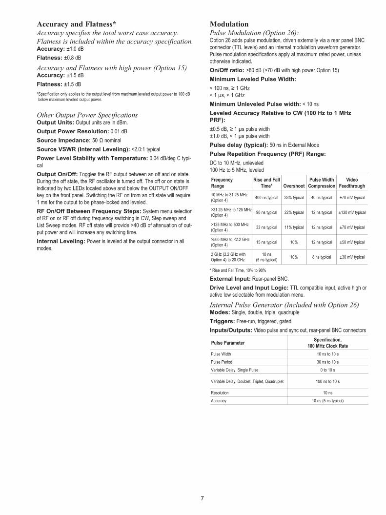
ModulationPulse Modulation (Option 26):Option 26 adds pulse modulation, driven externally via a rear panel BNC connector(TTLlevels)andaninternalmodulationwaveformgenerator.Pulse modulation specifications apply at maximum rated power, unless otherwise indicated.On/Off ratio: >80 dB (>70 dB with high power Option 15)Minimum Leveled Pulse Width:<100ns,≥1GHz < 1 µs, < 1 GHzMinimum Unleveled Pulse width: < 10 nsLeveled Accuracy Relative to CW (100 Hz to 1 MHz PRF):±0.5dB,≥1µspulsewidth ±1.0 dB, < 1 µs pulse widthPulse delay (typical): 50 ns in External ModePulse Repetition Frequency (PRF) Range:DC to 10 MHz, unleveled 100 Hz to 5 MHz, leveled Frequency Range
Rise and Fall Time*
Overshoot
Pulse Width Compression
Video Feedthrough
10 MHz to 31.25 MHz (Option 4) 400 ns typical 33% typical 40 ns typical ±70 mV typical
>31.25 MHz to 125 MHz (Option 4) 90 ns typical 22% typical 12 ns typical ±130 mV typical
>125 MHz to 500 MHz (Option 4) 33 ns typical 11% typical 12 ns typical ±70 mV typical
>500 MHz to <2.2 GHz (Option 4) 15 ns typical 10% 12 ns typical ±50 mV typical
2 GHz (2.2 GHz with Option 4) to 20 GHz
10 ns (5 ns typical) 10% 8 ns typical ±30 mV typical
* Rise and Fall Time, 10% to 90%
External Input: Rear-panel BNC.Drive Level and Input Logic:TTLcompatibleinput,activehighoractive low selectable from modulation menu.
Internal Pulse Generator (Included with Option 26)Modes: Single, double, triple, quadrupleTriggers: Free-run, triggered, gatedInputs/Outputs: Video pulse and sync out, rear-panel BNC connectors
Pulse ParameterSpecification,
100 MHz Clock Rate
Pulse Width 10 ns to 10 s
Pulse Period 30 ns to 10 s
Variable Delay, Single Pulse 0 to 10 s
Variable Delay, Doublet, Triplet, Quadruplet 100 ns to 10 s
Resolution 10 ns
Accuracy 10 ns (5 ns typical)
8
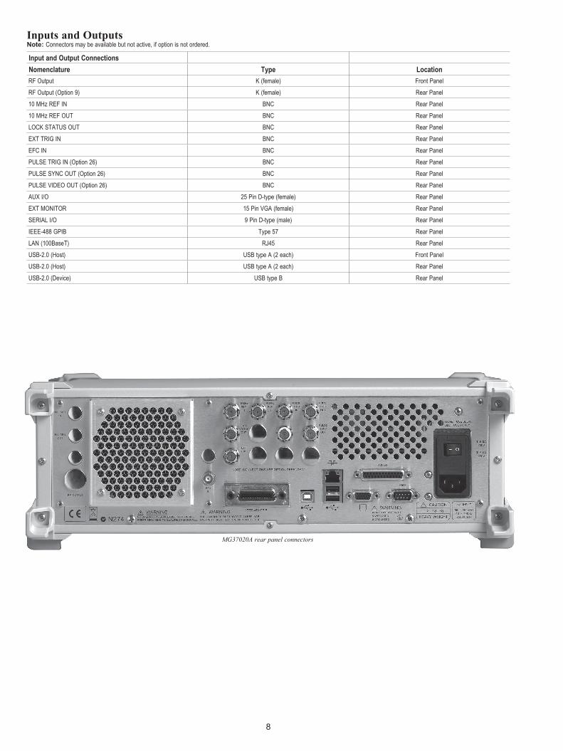
Inputs and OutputsNote: Connectors may be available but not active, if option is not ordered.
MG37020A rear panel connectors
Input and Output Connections
Nomenclature Type Location
RF Output K (female) Front Panel
RF Output (Option 9) K (female) Rear Panel
10 MHz REF IN BNC Rear Panel
10 MHz REF OUT BNC Rear Panel
LOCKSTATUSOUT BNC Rear Panel
EXTTRIGIN BNC Rear Panel
EFC IN BNC Rear Panel
PULSETRIGIN(Option26) BNC Rear Panel
PULSESYNCOUT(Option26) BNC Rear Panel
PULSEVIDEOOUT(Option26) BNC Rear Panel
AUXI/O 25 Pin D-type (female) Rear Panel
EXTMONITOR 15 Pin VGA (female) Rear Panel
SERIALI/O 9 Pin D-type (male) Rear Panel
IEEE-488 GPIB Type 57 Rear Panel
LAN(100BaseT) RJ45 Rear Panel
USB-2.0 (Host) USB type A (2 each) Front Panel
USB-2.0 (Host) USB type A (2 each) Rear Panel
USB-2.0 (Device) USB type B Rear Panel
9
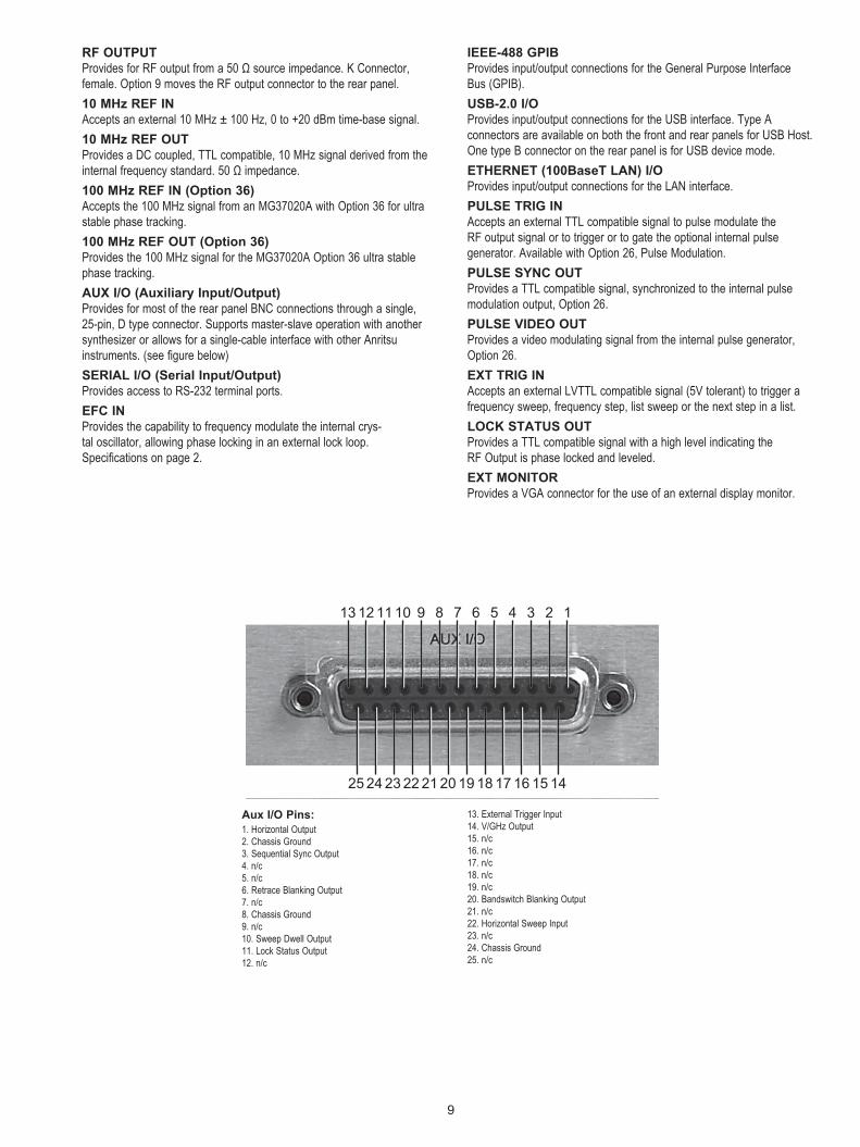
RF OUTPUTProvidesforRFoutputfroma50Ωsourceimpedance.KConnector,female. Option 9 moves the RF output connector to the rear panel.10 MHz REF INAccepts an external 10 MHz ± 100 Hz, 0 to +20 dBm time-base signal.10 MHz REF OUTProvidesaDCcoupled,TTLcompatible,10MHzsignalderivedfromtheinternalfrequencystandard.50Ωimpedance.100 MHz REF IN (Option 36)Accepts the 100 MHz signal from an MG37020A with Option 36 for ultra stable phase tracking.100 MHz REF OUT (Option 36)Provides the 100 MHz signal for the MG37020A Option 36 ultra stable phase tracking.AUX I/O (Auxiliary Input/Output)Provides for most of the rear panel BNC connections through a single, 25-pin, D type connector. Supports master-slave operation with another synthesizer or allows for a single-cable interface with other Anritsu instruments. (see figure below)SERIAL I/O (Serial Input/Output)Provides access to RS-232 terminal ports.EFC INProvides the capability to frequency modulate the internal crys-tal oscillator, allowing phase locking in an external lock loop. Specifications on page 2.
IEEE-488 GPIBProvides input/output connections for the General Purpose Interface Bus (GPIB).USB-2.0 I/OProvides input/output connections for the USB interface. Type A connectors are available on both the front and rear panels for USB Host. One type B connector on the rear panel is for USB device mode.ETHERNET (100BaseT LAN) I/OProvidesinput/outputconnectionsfortheLANinterface.PULSE TRIG INAcceptsanexternalTTLcompatiblesignaltopulsemodulatethe RF output signal or to trigger or to gate the optional internal pulse generator. Available with Option 26, Pulse Modulation.PULSE SYNC OUTProvidesaTTLcompatiblesignal,synchronizedtotheinternalpulse modulation output, Option 26.PULSE VIDEO OUTProvides a video modulating signal from the internal pulse generator, Option 26.EXT TRIG INAcceptsanexternalLVTTLcompatiblesignal(5Vtolerant)totriggera frequency sweep, frequency step, list sweep or the next step in a list.LOCK STATUS OUTProvidesaTTLcompatiblesignalwithahighlevelindicatingtheRF Output is phase locked and leveled.EXT MONITORProvides a VGA connector for the use of an external display monitor.
Aux I/O Pins:1. Horizontal Output2. Chassis Ground3. Sequential Sync Output4. n/c5. n/c6. Retrace Blanking Output7. n/c8. Chassis Ground9. n/c10. Sweep Dwell Output11.LockStatusOutput12. n/c
13. External Trigger Input14. V/GHz Output15. n/c16. n/c17. n/c18. n/c19. n/c20. Bandswitch Blanking Output21. n/c22. Horizontal Sweep Input23. n/c24. Chassis Ground25. n/c
25 1415161718192021222324
12345678910111213 12345678910111213
25 1415161718192021222324

10
Ordering InformationModelMG37022A2 to 20 GHz Fast Switching Signal Generator
OptionsMG37022A-001 Rack Mount with Slides - Kit contains a set
of track slides, mounting ears and front panel handles for a standard 19 inch equipment rack.
MG37022A-002 Mechanical Step Attenuator - Adds a 110 dB range, 10 dB/step attenuator. RF output power is reduced.
MG37022A-004 10 MHz to 2.2 GHz RF Coverage - Uses a digital down converter to significantly reduce SSB phase noise
MG37022A-009 Rear Panel Output - Moves the RF output connector to the rear panel.
MG37022A-015 High Power - Adds high-power RF compo-nents to the instrument to increase the output power level.
MG37022A-017 Delete Front Panel - Deletes the front panel for use in remote controlled applications. (Only available with Option 1)
MG37022A-026 Pulse Modulation - Includes internal waveform generator and external input via a rear panel BNC connector.
MG37022A-035 Removable Hard Drive - Provides the capa-bility to remove the internal hard drive, and includes one replacement hard drive with instrument software.
MG37022A-036 Ultra Stable Phase Track - Provides the capability for ultra-stable phase track-ing between instruments using the internal 100 MHz reference.
MG37022A-037 Performance Suite – For ease of ordering and package pricing, this option bundles Options 2, 4, 15 and 26.
MG37022A-088 250µsecSwitchingSpeedLimit-Limitsthe frequency switching speed to 250 µsec to comply with United States Export Control regulations
MG37022A-098 Standard Calibration to ISO17025 and ANSI/NCSLZ540.Providesacalibrationcertificate,decal and “Calibration void if removed” tamper seals.
MG37022A-099 Premium Calibration to ISO17025 and ANSI/NCSLZ540.ProvideseverythingincludedwithOption 98 plus test report and uncertainty data.
Optional Accessories34RKNF50 DC to 20 GHz ruggedized K male to Type-N
female adapter.63270 Transit case (16 kg, 65 cm x 81 cm, roll-away
on two wheels).806-97 AUXI/Ocable,25pintoBNC:Sequential
Sync, Marker Out, Bandswitch Blanking, Retrace Blanking, Sweep Dwell In, V/GHz and Horizontal Out.

11

Technical Data Sheet No. 11410-00429, Rev. H Printed in United States 2011-03©2011 Anritsu Company. All Rights Reserved
® Anritsu All trademarks are registered trademarks of their respective companies. Data subject to change without notice. For the most recent specifications visit: www.us.anritsu.com
Anritsu Corporation5-1-1 Onna, Atsugi-shi, Kanagawa, 243-8555 Japan Phone: +81-46-223-1111 Fax: +81-46-296-1238
• U.S.A. Anritsu Company1155 East Collins Boulevard, Suite 100, Richardson, TX, 75081 U.S.A. Toll Free: 1-800-ANRITSU (267-4878) Phone: +1-972-644-1777 Fax: +1-972-671-1877• Canada Anritsu Electronics Ltd.700 Silver Seven Road, Suite 120, Kanata, Ontario K2V 1C3, Canada Phone: +1-613-591-2003 Fax: +1-613-591-1006
• Brazil Anritsu Electrônica Ltda.Praça Amadeu Amaral, 27 - 1 Andar 01327-010 - Bela Vista - São Paulo - SP - Brasil Phone: +55-11-3283-2511 Fax: +55-11-3288-6940
• Mexico Anritsu Company, S.A. de C.V.Av. Ejército Nacional No. 579 Piso 9, Col. Granada 11520 México, D.F., México Phone: +52-55-1101-2370 Fax: +52-55-5254-3147
• U.K. Anritsu EMEA Ltd.200 Capability Green, Luton, Bedfordshire LU1 3LU, U.K. Phone: +44-1582-433280 Fax: +44-1582-731303
• France Anritsu S.A.12 Avenue du Québec, Bâtiment Iris 1-Silic 638, 91140 VILLEBON SUR YVETTE, France Phone: +33-1-60-92-15-50 Fax: +33-1-64-46-10-65
• Germany Anritsu GmbHNemetschek Haus, Konrad-Zuse-Platz 1 81829 München, Germany Phone: +49 (0) 89 442308-0 Fax: +49 (0) 89 442308-55
• Italy Anritsu S.p.A.Via Elio Vittorini, 129, 00144 Roma, Italy Phone: +39-06-509-9711 Fax: +39-06-502-2425
• Sweden Anritsu ABBorgafjordsgatan 13, 164 40 KISTA, Sweden Phone: +46-8-534-707-00 Fax: +46-8-534-707-30
• Finland Anritsu ABTeknobulevardi 3-5, FI-01530 VANTAA, Finland Phone: +358-20-741-8100 Fax: +358-20-741-8111
• Denmark Anritsu A/S (for Service Assurance) Anritsu AB (for Test & Measurement)Kirkebjerg Allé 90 DK-2605 Brøndby, Denmark Phone: +45-7211-2200 Fax: +45-7211-2210
• RussiaAnritsu EMEA Ltd. Representation Office in RussiaTverskaya str. 16/2, bld. 1, 7th floor. Russia, 125009, Moscow Phone: +7-495-363-1694 Fax: +7-495-935-8962
• United Arab Emirates Anritsu EMEA Ltd. Dubai Liaison OfficeP O Box 500413 - Dubai Internet City Al Thuraya Building, Tower 1, Suite 701, 7th Floor Dubai, United Arab Emirates Phone: +971-4-3670352 Fax: +971-4-3688460
• Singapore Anritsu Pte. Ltd.60 Alexandra Terrace, #02-08, The Comtech (Lobby A) Singapore 118502 Phone: +65-6282-2400 Fax: +65-6282-2533
• India Anritsu Pte. Ltd. India Branch Office3rd Floor, Shri Lakshminarayan Niwas, #2726, 80 ft Road, HAL 3rd Stage, Bangalore - 560 075, India Phone: +91-80-4058-1300 Fax: +91-80-4058-1301
• P. R. China (Hong Kong) Anritsu Company Ltd.Units 4 & 5, 28th Floor, Greenfield Tower, Concordia Plaza, No. 1 Science Museum Road, Tsim Sha Tsui East, Kowloon, Hong Kong, P.R. China Phone: +852-2301-4980 Fax: +852-2301-3545
• P. R. China (Beijing) Anritsu Company Ltd. Beijing Representative OfficeRoom 2008, Beijing Fortune Building, No. 5 , Dong-San-Huan Bei Road, Chao-Yang District, Beijing 100004, P.R. China Phone: +86-10-6590-9230Fax: +86-10-6590-9235
• Korea Anritsu Corporation, Ltd.8F Hyunjuk Bldg. 832-41, Yeoksam-Dong, Kangnam-ku, Seoul, 135-080, Korea Phone: +82-2-553-6603 Fax: +82-2-553-6604
• Australia Anritsu Pty Ltd.Unit 21/270 Ferntree Gully Road, Notting Hill Victoria, 3168, Australia Phone: +61-3-9558-8177 Fax: +61-3-9558-8255
• Taiwan Anritsu Company Inc.7F, No. 316, Sec. 1, Neihu Rd., Taipei 114, Taiwan Phone: +886-2-8751-1816 Fax: +886-2-8751-1817