Embed Size (px)
Citation preview

©TIMBER QUEENSLAND LIMITED TECHNICAL DATA SHEET 19 PERGOLAS AND CARPORTS Revised March 2014 Page 1
This data sheet contains Timber Queensland’s recommendations for attached and detached timber pergolas and carports with relatively flat skillion roofs and lightweight roofing (max 10 kg/m2). It covers the most common timber species, sizes and fixing methods. Where appropriate, separate tables are provided for low wind speed areas (N1, N2, N3 and C1) and higher wind speed area (N4 and C2). Wind classification C3 is beyond the scope of this data sheet. For alternative stress grades, fixing methods, larger spans, pitched roofs, wind classification C3 etc., refer AS 1684 – Residential timber-framed construction.Note: The sizes and fixings assume pergolas are either roofed (lightweight roofing 10 kg/m3), or could have a roof installed at some future stage.
TIMBER SELECTIONPergola and carport framing exposed to the weather, including posts fixed above ground, shall be either preservative treated pine, durability class 1 or 2 hardwood, or cypress.
Posts embedded in the ground shall be in-ground durability class 1 hardwood, preservative treated pine or cypress (sapwood free).
Hardwood posts and framing containing sapwood shall be preservative treated.
Preservative treatment for posts in the ground shall be H5. Exposed framing and posts above ground shall be treated to H3.
Note: Lower durability timbers (e.g. Oregon, Tasmanian Oak, Victorian Ash) are not recommended for pergolas unless fully protected by a roof.
MEMBER SIZESTables 1, 2, 5 and 10 list the recommended sizes and spans for the most commonly available timber species. For alternative species and larger spans refer AS 1684.
Note: When appropriate separate tables are provided for different wind classifications. Tables with a suffix L are for low wind speed areas (N1, N2, N3 and C1). Tables with a suffix H are for higher wind speed areas (N4 and C2).
FIXINGSFixings (stirrups, brackets, bolts, nails etc.) shall be either hot dipped galvanised or stainless steel.
Tables 3, 4, 7, 8, 9, 10, 11 and 12 contain recommended fixings between the various members. For alternative fixing methods refer AS 1684.
Note: When appropriate separate tables are provided for different wind classifications. Tables with a suffix L are for low wind speed areas (N1, N2, N3 and C1). Tables with a suffix H are for higher wind speed areas (N4 and C2).
RECOMMENDED PRACTICE // MARCH 2014
PERGOLAS AND CARPORTS
TECHNICAL DATA SHEETISSUED BY TIMBER QUEENSLAND
19
Battens
Footing
Knee Brace
Beam
Post
Hot dippedgalvanised stirrup
Ends of rafters andbeams shaped toreduce end grainexposure
Ledger
Rafter
Lightweight roo�ng(max. 10kg/m2) Note:
Fascias, gutters,downpipes, etc.may be required.
Double diagonalbracing betweenposts in both directions
(a) Typical attached pergola
Battens
Footing
Knee Brace
Beam
Post
Hot dippedgalvanised stirrup
Ends of rafters andbeams shaped toreduce end grainexposure
Ledger
Rafter
Lightweight roo�ng(max. 10kg/m2) Note:
Fascias, gutters,downpipes, etc.may be required.
Double diagonalbracing betweenposts in both directions
(b) Typical freestanding carport
Figure 1 - Terminology

©TIMBER QUEENSLAND LIMITED TECHNICAL DATA SHEET 19 PERGOLAS AND CARPORTS Revised March 2014 Page 2
TIMBER POSTSTable 1 lists the sizes for timber posts.
TABLE 1 - TIMBER POSTS - SUPPORTING PERGOLA OR CARPORT ROOF (MAX. 10 KG/M2)
Roof Area Supported
(m2)5 10 20
Member Size (mm)
Maximum Post Height (mm)
UnseasonedCypress F5
75 x 75 100 x 100
3400 4800
2400 4200
N/S 3000
Seasoned TreatedPine F7
70 x 7090 x 90
35004800
25004100
N/S2900
UnseasonedHardwood F14
75 x 75100 x 100
48004800
34004800
24004200
Treated PineRounds F8
100 dia 125 dia150 dia
480048004800
340048004800
N/S36004800
ATTACHING POSTS TO TIMBER DECKSPosts supporting roofs or pergolas over timber decks shall occur directly over deck supports. Posts supporting decks and roofs may be continuous from ground to roof beams with deck bearers fixed to sides of posts (refer Technical Data Sheet 4). Alternatively, posts supporting roofs shall be fixed to bearers with the required fixing type listed in Tables 3 and 4.
INSTALLING POSTS IN GROUNDSawn timber posts should preferably be fixed to hot dipped galvanised steel stirrups set in concrete. A minimum clearance of 75 mm shall be provided between the top of the concrete footing or paving and the bottom of the post as a termite inspection zone.
Posts embedded in the ground shall be provided with stainless steel mesh socks (TermiMesh) or alternatively the surrounding ground shall be chemically treated.
Holes for embedded posts shall be filled with 100 mm depth of coarse gravel (to allow water to drain) before backfilling with concrete or rammed earth. Top of backfill shall be sloped away from posts to shed water. Footings to be engineer designed for both bearing and uplift.
beamoverhang
Half beamspan
Half beamspan
Half beamspan
Roof Area Supported(Post A) =(Post B) =
rafteroverhang
Half rafterspan
Hot dippedgalvanised stirrup
Top of footingslopped away
from post
Concretefooting orrammedearth back�ll
100 mm
75 mm
Course gravel laid atthe base of the post
Concrete footing
(a) Fixed to stirrup (b) Embedded in ground
Figure 3 - Installing posts
beamoverhang
Half beamspan
Half beamspan
Half beamspan
Roof Area Supported(Post A) =(Post B) =
rafteroverhang
Half rafterspan
Hot dippedgalvanised stirrup
Top of footingslopped away
from post
Concretefooting orrammedearth back�ll
100 mm
75 mm
Course gravel laid atthe base of the post
Concrete footing
Figure 2 - Roof area supported by posts

©TIMBER QUEENSLAND LIMITED TECHNICAL DATA SHEET 19 PERGOLAS AND CARPORTS Revised March 2014 Page 3
PERGOLA OR CARPORT BEAMSTables 2L and 2H list the sizes and spans for pergola or carport beams in low wind speed and higher wind speed areas.
TABLE 2L - PERGOLA OR CARPORT BEAMS - (WIND CLASSIFICATIONS N1, N2, N3 AND C1)
Member Size
Roof Load Width1500 3000 4500 6000 1500 3000 4500 6000
Maximum Beam Span (mm)Single Span Continuous Span
UnseasonedCypressF5
100 x 50100 x 75125 x 50125 x 75150 x 50150 x 75175 x 50175 x 75200 x 50200 x 75
N/S170018002800280032003200370037004200
N/SN/SN/S
1800170023002200280026003100
N/SN/SN/SN/SN/S
17001600220021002600
N/SN/SN/SN/SN/SN/SN/S
180016002200
1800230025002900290034003300410038004700
N/S160016001900190026002300290027003300
N/SN/SN/S
1600160019001900230021002700
N/SN/SN/SN/SN/S
17001600190019002200
Seasoned Treated PineF7
90 x 45120 x 45140 x 45
2/140 x 35190 x 45
2/190 x 35240 x 45
2/240 x 35
N/S2000280037003800480049005600
N/SN/S
180026002700350033004600
N/SN/SN/S
21002100290027003600
N/SN/SN/S
15001600250023003100
18002600290038003900530051006700
N/S1700190027002800360034004600
N/SN/S
160021002100300029003800
N/SN/SN/S
19001900270024003200
UnseasonedHardwoodF14
100 x 50100 x 75125 x 50125 x 75150 x 50150 x 75175 x 50175 x 75200 x 50200 x 75250 x 50250 x 75
200027002900320035003800400043004400470051005400
190022002500280029003300340038003800420046004900
N/S19002000250026002900300034003400390042004600
N/SN/S
1500220021002700260031002900360037004300
300036003800430045004900500053005500580063006700
210027002700320032004000380046004400530055006100
170020002100270027003200310037003500430045005500
N/S18001900230022002800270032003100370038004700
Note: Maximum overhang shall be 25% of the actual backspan.
TABLE 2H - PERGOLA OR CARPORT BEAMS - (WIND CLASSIFICATIONS N4 AND C2)
Member Size
Roof Load Width1500 3000 4500 6000 1500 3000 4500 6000
Maximum Beam Span (mm)Single Span Continuous Span
UnseasonedCypressF5
100 x 50100 x 75125 x 50125 x 75150 x 50150 x 75175 x 50175 x 75200 x 50200 x 75
N/SN/S
16002200220027002600320030003700
N/SN/SN/SN/SN/S
17001600220021002600
N/SN/SN/SN/SN/SN/SN/S
1500N/S
2000
N/SN/SN/SN/SN/SN/SN/SN/SN/S
1500
N/S180019002500230028002800330031003800
N/SN/SN/S
1600160019001900230021002700
N/SN/SN/SN/SN/S
1600N/S
190017002100
N/SN/SN/SN/SN/SN/SN/S
1600N/S
1800Seasoned Treated PineF7
90 x 45120 x 45140 x 45
2/140 x 35190 x 45
2/190 x 35240 x 45
2/240 x 35
N/S1700220030003000420039005300
N/SN/SN/S
20002100290027003600
N/SN/SN/SN/SN/S
230022002900
N/SN/SN/SN/SN/S
190017002600
N/S1900230031003200430040005400
N/SN/S
160021002100300028003700
N/SN/SN/S
17001800260022003100
N/SN/SN/SN/SN/S
200019002700
UnseasonedHardwoodF14
100 x 50100 x 75125 x 50125 x 75150 x 50150 x 75175 x 50175 x 75200 x 50200 x 75250 x 50250 x 75
200027002900320035003800400043004400470051005400
N/S19002000260026003000290036003400420044004900
N/SN/SN/S
200020002500240029002800330035004400
N/SN/SN/S
150015002100200026002400290030003700
260030003100370037004600440053005100580063006700
170020002100270027003200310037003500430045005400
N/S17001700210020002700260031002900340036004400
N/SN/SN/S
180018002200210027002600300031003800
Note: Maximum overhang shall be 25% of the actual backspan.

©TIMBER QUEENSLAND LIMITED TECHNICAL DATA SHEET 19 PERGOLAS AND CARPORTS Revised March 2014 Page 4
Post
Spacer block
Double nailat both ends
Beam A
Roof Load Widthfor Beam A
Roof Load Widthfor Beam B
span span span
Beam B
Overhang
35 mm (min.)
2 bolt Ø5 bolt Ø4 bolt Ø
Post
6 bolt Ø
4 bolt Ø5 bolt Ø2 bolt Ø
6 bolt Ø
Bolts are per Table
35 mm (min.)
150x90x10 mmM.S. angle
Bolts asper table
Figure 4 - Roof load width
FIXING BEAMS TO POSTSBeams shall be fixed to posts as listed in Tables 3 & 4. Where beams are housed into posts, a minimum of 35 mm of post shall remain.Alternatively, beams can be fixed to posts with proprietary galvanised steel brackets in accordance with manufacturer’s recommendations.
MULTIPLE BEAMSWhere covered by a roof, double beams may be either spaced apart (with a solid timber separating block at mid-span) or nail laminated together to form a single beam. Fully exposed double beams in unroofed pergolas shall be spaced.
Post
Spacer block
Double nailat both ends
Beam A
Roof Load Widthfor Beam A
Roof Load Widthfor Beam B
span span span
Beam B
Overhang
35 mm (min.)
2 bolt Ø5 bolt Ø4 bolt Ø
Post
6 bolt Ø
4 bolt Ø5 bolt Ø2 bolt Ø
6 bolt Ø
Bolts are per Table
35 mm (min.)
150x90x10 mmM.S. angle
Bolts asper table
Figure 5 - Multiple beamsTABLE 3 - FIXING TYPES - POSTS TO BEARERS OR BEAMS
Fixing Type Description
Post
Spacer block
Double nailat both ends
Beam A
Roof Load Widthfor Beam A
Roof Load Widthfor Beam B
span span span
Beam B
Overhang
35 mm (min.)
2 bolt Ø5 bolt Ø4 bolt Ø
Post
6 bolt Ø
4 bolt Ø5 bolt Ø2 bolt Ø
6 bolt Ø
Bolts are per Table
35 mm (min.)
150x90x10 mmM.S. angle
Bolts asper table
P1P2P3P4
1/M10 bolt1/M12 bolt2/M10 bolts2/M12 bolts
Post
Spacer block
Double nailat both ends
Beam A
Roof Load Widthfor Beam A
Roof Load Widthfor Beam B
span span span
Beam B
Overhang
35 mm (min.)
2 bolt Ø5 bolt Ø4 bolt Ø
Post
6 bolt Ø
4 bolt Ø5 bolt Ø2 bolt Ø
6 bolt Ø
Bolts are per Table
35 mm (min.)
150x90x10 mmM.S. angle
Bolts asper table
P5P6P7
2/M10 bolts2/M12 bolts2/M16 bolts
TABLE 4L - FIXING REQUIREMENTS - POSTS TO BEARERS OR BEAMS (WIND CLASSIFICATIONS N1, N2, N3 AND C1)
Roof Area Supported (m2)
5 10 15 20Fixing types permitted
Unseasoned Cypress F5(J3)
P4P5 P5 P6 P7
Seasoned Treated Pine F7(JD4)
P3P5 P5 P6 P6
Unseasoned Hardwood F14 (J2)
P1P5 P5 P6 P7
Note: For roof area supported refer Figure 2.
TABLE 4H - FIXING REQUIREMENTS - POSTS TO BEARERS OR BEAMS (WIND CLASSIFICATIONS N4 AND C2)
Roof Area Supported (m2)
5 10 15 20Fixing types permitted
Unseasoned Cypress F5(J3) P5 P6 P7 P7
Seasoned Treated Pine F7(JD4) P5 P6 P7 P7
Unseasoned Hardwood F14 (J2)
P4P5 P6 P7 P7
Note: For roof area supported refer Figure 2.

©TIMBER QUEENSLAND LIMITED TECHNICAL DATA SHEET 19 PERGOLAS AND CARPORTS Revised March 2014 Page 5
PERGOLA OR CARPORT RAFTERSTables 5L and 5H list the sizes and spans for pergola or carport rafters in low wind speed and higher wind speed areas.
TABLE 5L - PERGOLA OR CARPORT RAFTERS - (WIND CLASSIFICATION N1, N2, N3 AND C1)
Member Size
Rafter Spacing600 900 600 900
Maximum Rafter Span (mm)Single Span Continuous Span
UnseasonedCypressF5
100 x 38100 x 50125 x 38125 x 50150 x 38150 x 50175 x 38175 x 50200 x 38200 x 50
2000230030003400380040004300460049005100
1800210028003100340037004000420045004800
2400300036004200440051005200600060006900
2200250028003300350040004100480048005500
Seasoned Treated PineF7
90 x 3590 x 45
120 x 35120 x 45140 x 35140 x 45190 x 35190 x 45240 x 35240 x 45
1900220032003800430048005900620072007200
1800200030003400350040004900560062007100
2400270038004300450051006100700072007200
2200250030003400350040004900560062007100
UnseasonedHardwoodF14
100 x 38100 x 50125 x 38125 x 50150 x 38150 x 50175 x 38175 x 50200 x 38200 x 50250 x 38250 x 50
270032003700390044004600500052005600580067007000
250030003400370041004300470049005200550063006600
350043005100540060006300680071007200720072007200
320039004700500055005900630067007100720072007200
Notes: For unnotched rafters, maximum overhang shall be 25% of the actual backspan. For notched rafters, overhang limits shall be in accordance with AS 1684.
TABLE 5H - PERGOLA OR CARPORT RAFTERS - (WIND CLASSIFICATION N4 AND C2)
Member Size
Rafter Spacing600 900 600 900
Maximum Rafter Span (mm)Single Span Continuous Span
UnseasonedCypressF5
100 x 38100 x 50125 x 38125 x 50150 x 38150 x 50175 x 38175 x 50200 x 38200 x 50
2000230029003400350040004200460048005100
1700200022002600280032003300380038004400
2300260029003400350041004200480048005600
1700200022002600280032003300380038004400
Seasoned Treated PineF7
90 x 3590 x 45
120 x 35120 x 45140 x 35140 x 45190 x 35190 x 45240 x 35240 x 45
1900220030003500360041004900560063007200
1700200024002700280032003900450050005700
2200260030003500360041004900560063007200
1700200024002700280032003900450050005700
UnseasonedHardwoodF14
100 x 38100 x 50125 x 38125 x 50150 x 38150 x 50175 x 38175 x 50200 x 38200 x 50250 x 38250 x 50
270032003700390044004600500052005600580067007000
250030003400370041004300470049005200550063006600
350043004800540058006300680071007200720072007200
300034003800440046005300550063006300720072007200
Notes: For unnotched rafters, maximum overhang shall be 25% of the actual backspan. For notched rafters, overhang limits shall be in accordance with AS 1684.
©TIMBER QUEENSLAND LIMITED TECHNICAL DATA SHEET 19 PERGOLAS AND CARPORTS Revised March 2014 Page 6
ATTACHING PERGOLA OR CARPORT TO HOUSEProvided the wall frame of the house is checked to ensure it can carry the additional load, pergolas and carports can be attached to the wall (refer method W1).
Provided the wall frame is adequate, and the house roof frame and tie-down fixings are checked and increased where necessary to ensure it can carry the additional load, and withstand the additional uplift (refer Table 6), pergolas and carports can be attached to fascias/eaves.
Pergolas and carports may be attached to the fascias/eaves by methods F1, F2 and F3 as allowed in Table 7L and 7H.-
The maximum overhang of house rafters or trusses shall not exceed 750 mm from outside of top plate to end of rafter/ truss.
For sheet roofed houses with 900 mm rafter spacing in wind classification N4 or C2, the minimum size of F5 or MGP 10 rafters (or top chords) shall be 90 x 45 mm. In all other cases, the minimum size of house rafters (or top chords) shall be 90 x 35 mm.
Timber fascias shall be minimum 190 x 25 mm.
Metal fascias shall be stiffened with 150 x 50 mm nogging and 100 x 38 mm ledger as shown on detail.
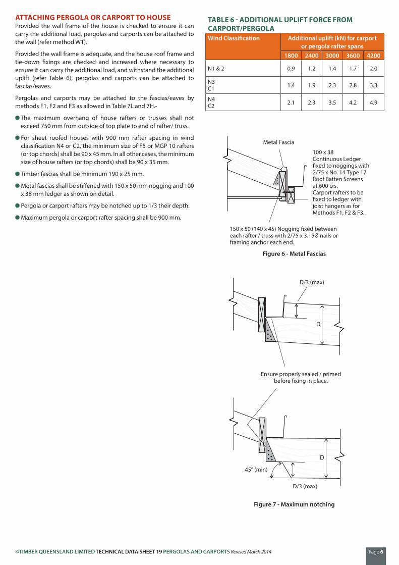
Pergola or carport rafters may be notched up to 1/3 their depth.
Maximum pergola or carport rafter spacing shall be 900 mm.
TABLE 6 - ADDITIONAL UPLIFT FORCE FROM CARPORT/PERGOLAWind Classification Additional uplift (kN) for carport
or pergola rafter spans1800 2400 3000 3600 4200
N1 & 2 0.9 1.2 1.4 1.7 2.0
N3C1 1.4 1.9 2.3 2.8 3.3
N4C2 2.1 2.3 3.5 4.2 4.9
Metal Fascia
100 x 38Continuous Ledger�xed to noggings with2/75 x No. 14 Type 17Roof Batten Screensat 600 crs.Carport rafters to be�xed to ledger withjoist hangers as forMethods F1, F2 & F3.
150 x 50 (140 x 45) Nogging �xed betweeneach rafter / truss with 2/75 x 3.15Ø nails orframing anchor each end.
D/3 (max)
Ensure properly sealed / primedbefore �xing in place.
D/3 (max)
45° (min)
Figure 6 - Metal Fascias
Figure 7 - Maximum notching

©TIMBER QUEENSLAND LIMITED TECHNICAL DATA SHEET 19 PERGOLAS AND CARPORTS Revised March 2014 Page 7
(a) Method F1 (c) Method F3
(b) Method F2 (d) Method W1
Check existingtie-down and wall frame
for adequacy
Check existingtie-down and wall frame
for adequacy
Ledger 70 x 35 F5 (MGP10)�xed to each stud with 1/75
No. 14 Type 17 Batten Screw
Check existingtie-down and wall frame
for adequacy
Check existingwall frame for
adequacy for extraroof dead load
AlternativeJoist Hanger
Timber Fascia190 x 25 (min)
Timber Fascia190 x 25 (min)
Hanger
Hanger
Fascia �xed torafter / truss ends with3/75 x 3.15 grooved�at head nails
Fascia �xed totop chord/rafter ends with1/75 No 14 Type 17 Screwplus 2/75 x 3.15 Ø nails
Joist Hanger 3/30 x 2.8 Ø nails eachside to rafter, 4/30 x 2.8 Ø nailseach leg to fascia.
Joist Hanger 3/30 x 2.8 Ø nails eachside to rafter, 4/30 x 2.8 Ø nailseach leg to fascia.
Ledger 90 x 35 F5 (MGP10)�xed to each stud or lintel with1/75 No. 14 Type 17 Batten Screw
2/framing anchors4/30 x 2.8 Ø nails to each leg
Flash/seal asappropriate
Remove existing fascia
Carport / PergolaRafter
So�t Trimer
Carport / PergolaRafter
So�t Trimer
90 x 35 F8 (MGP12) Sti�ener �xed to top chordwith 75 x 3.15 Ø nails staggered at 200 crs or75 x No. 14 Type 17 Batten Screws at 400 crs
Joist Hanger 3/30 x 2.8 Ø nails eachside to rafter, 4/30 x 2.8 Ø nailseach leg to fascia.
3/75 x 3.15 Ø nails
Trimmer 70 x 35 F5Carport / Pergola
Rafter
Carport / PergolaRafter
Fascia �xed torafter / truss ends with1/75 Batten Screw plus2/75 x 3.15 Ø nails
Trimmer �xed to ledger with2/framing anchors 4/30 x 2.8 Ø nailsto trimmer and 4/30 x 2.8 Ø nails toledger each leg
Figure 8 - Methods for attaching pergola and carport to house
TABLE 7L - ATTACHING PERGOLA OR CARPORT TO HOUSE (WIND CLASSIFICATIONS N1, N2, N3 AND C1)House Roof Acceptable method of attachmentRoof Type (rafter spacing)
Rafter/Truss Stress Grade
Pergola/carport rafter span (mm)2400 3000 3600 4200
Tile(600 mm)
F5 (MGP 10)F2F3W1
F2F3W1
F2F3W1
F3W1
F8 (MGP 12) or better
F1F2F3W1
F2F3W1
F2F3W1
F3W1
Sheet(900 mm)
F5 (MGP 10)F2F3W1
F3W1
F3W1
F3W1
F8 (MGP 12) or betterF2F3W1
F3W1
F3W1
F3W1
Note: Method F1 may also be used (in wind classifications N1 and N2 only) for F5 (MGP10) pergola or carport rafters up to 2700 mm span, and for F8 (MGP12) or better pergola or carport rafters up to 4200 mm span.
TABLE 7H - ATTACHING PERGOLA OR CARPORT TO HOUSE (WIND CLASSIFICATIONS N4 AND C2)House Roof Acceptable method of attachmentRoof Type (rafter spacing)
Rafter/Truss Stress Grade
Pergola/carport rafter span (mm)Up to 2700 Exceeding 2700
Tile(600 mm)
F5 (MGP 10) F3W1 W1
F8 (MGP 12) or better F3W1 W1
Sheet(900 mm)
F5 (MGP 10) F3W1 W1
F8 (MGP 12) or better F3W1 W1

©TIMBER QUEENSLAND LIMITED TECHNICAL DATA SHEET 19 PERGOLAS AND CARPORTS Revised March 2014 Page 8
TABLE 9L - FIXING REQUIREMENTS - RAFTERS TO PERGOLA OR CARPORT BEAMS (WIND CLASSIFICATIONS N1, N2, N3 AND C1)
Roof Area Supported (m2)
2 4 6Fixing types permitted
Unseasoned Cypress F5(J3)
R1R3R5R8
R4R6R8 R8
Seasoned Treated Pine F7(JD4)
R1R3R5R8
R4R6R8 R9
Unseasoned Hardwood F14 (J2)
R1R3R5R8
R2R4R6R8
R4R6R8
TABLE 9H - FIXING REQUIREMENTS - RAFTERS TO PERGOLA OR CARPORT BEAMS (WIND CLASSIFICATIONS N4 AND C2)
Roof Area Supported (m2)
2 4 6Fixing types permitted
Unseasoned Cypress F5(J3)
R2R4R6R8 R8 R8
Seasoned Treated Pine F7(JD4)
R2R4R6R8 R9 R9
Unseasoned Hardwood F14 (J2)
R2R3R5R8
R4R6R8 R8
FIXING RAFTERS TO BEAMS OR LEDGERSPergola and carport rafters shall be fixed to beams with the fixing type listed in Tables 8 and 9.
TABLE 8 - FIXING TYPES - RAFTERS TO PERGOLA OR CARPORT BEAMS
Fixing Type Description
Framing anchorsas per table,4/2.8 dia nailsin each leg
Nominalnailing
30x0.8 mm strap with3/2.8 mm Ø nailseach end as per table
30x0.8 mm strap with3/2.8 mm Ø nailseach end as per table
Rafter thickness35 mm (min.)
75x50x5 mm MS anglewith 1/M10 bolt or40 mm No14 Type 17screws to rafter asper table
50 mm No14Type 17 screwsto beamas per table
Bolts as per table
R1
R2
1/galvanised framing anchor
2/galvanised framing anchors
Framing anchorsas per table,4/2.8 dia nailsin each leg
Nominalnailing
30x0.8 mm strap with3/2.8 mm Ø nailseach end as per table
30x0.8 mm strap with3/2.8 mm Ø nailseach end as per table
Rafter thickness35 mm (min.)
75x50x5 mm MS anglewith 1/M10 bolt or40 mm No14 Type 17screws to rafter asper table
50 mm No14Type 17 screwsto beamas per table
Bolts as per table
R3
R4
1/30 x 0.8 mm galvanised iron strap
2/30 x 0.8 mm galvanised iron strap
Framing anchorsas per table,4/2.8 dia nailsin each leg
Nominalnailing
30x0.8 mm strap with3/2.8 mm Ø nailseach end as per table
30x0.8 mm strap with3/2.8 mm Ø nailseach end as per table
Rafter thickness35 mm (min.)
75x50x5 mm MS anglewith 1/M10 bolt or40 mm No14 Type 17screws to rafter asper table
50 mm No14Type 17 screwsto beamas per table
Bolts as per table
R5
R6
R7
Fixings to each leg1/No.14 Type 17 screw
2/No.14 Type 17 screw
1/M10 bolt
Framing anchorsas per table,4/2.8 dia nailsin each leg
Nominalnailing
30x0.8 mm strap with3/2.8 mm Ø nailseach end as per table
30x0.8 mm strap with3/2.8 mm Ø nailseach end as per table
Rafter thickness35 mm (min.)
75x50x5 mm MS anglewith 1/M10 bolt or40 mm No14 Type 17screws to rafter asper table
50 mm No14Type 17 screwsto beamas per table
Bolts as per table
R8
R9
1/M10 bolt
1/M12 bolt
©TIMBER QUEENSLAND LIMITED TECHNICAL DATA SHEET 19 PERGOLAS AND CARPORTS Revised March 2014 Page 9
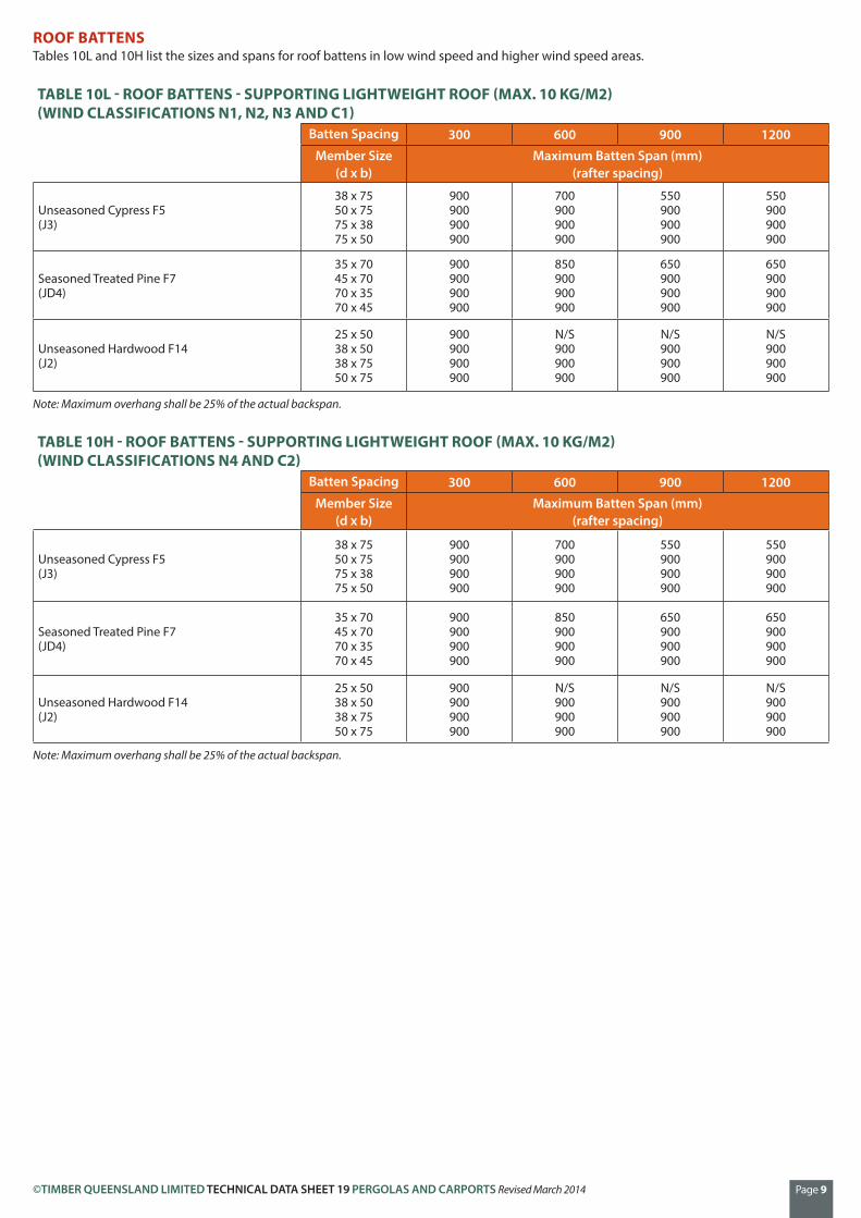
ROOF BATTENSTables 10L and 10H list the sizes and spans for roof battens in low wind speed and higher wind speed areas.
TABLE 10L - ROOF BATTENS - SUPPORTING LIGHTWEIGHT ROOF (MAX. 10 KG/M2) (WIND CLASSIFICATIONS N1, N2, N3 AND C1)
Batten Spacing 300 600 900 1200Member Size
(d x b)Maximum Batten Span (mm)
(rafter spacing)
Unseasoned Cypress F5(J3)
38 x 7550 x 7575 x 3875 x 50
900900900900
700900900900
550900900900
550900900900
Seasoned Treated Pine F7(JD4)
35 x 7045 x 7070 x 3570 x 45
900900900900
850900900900
650900900900
650900900900
Unseasoned Hardwood F14 (J2)
25 x 5038 x 5038 x 7550 x 75
900900900900
N/S900900900
N/S900900900
N/S900900900
Note: Maximum overhang shall be 25% of the actual backspan.
TABLE 10H - ROOF BATTENS - SUPPORTING LIGHTWEIGHT ROOF (MAX. 10 KG/M2) (WIND CLASSIFICATIONS N4 AND C2)
Batten Spacing 300 600 900 1200Member Size
(d x b)Maximum Batten Span (mm)
(rafter spacing)
Unseasoned Cypress F5(J3)
38 x 7550 x 7575 x 3875 x 50
900900900900
700900900900
550900900900
550900900900
Seasoned Treated Pine F7(JD4)
35 x 7045 x 7070 x 3570 x 45
900900900900
850900900900
650900900900
650900900900
Unseasoned Hardwood F14 (J2)
25 x 5038 x 5038 x 7550 x 75
900900900900
N/S900900900
N/S900900900
N/S900900900
Note: Maximum overhang shall be 25% of the actual backspan.

©TIMBER QUEENSLAND LIMITED TECHNICAL DATA SHEET 19 PERGOLAS AND CARPORTS Revised March 2014 Page 10
FIXING BATTENS TO RAFTERSPergola and carport roof battens shall be fixed to rafters with nails, screws or framing anchors as listed in Tables 11 and 12.
TABLE 11 - FIXING TYPES - ROOF BATTENS TO RAFTERS
Fixing Type Description
25x50 mm batten
Nails asper table
38 x 75 or38x50 mm batten
Nails orscrews as per table
Two nails or screws shall be usedonly with 75mm wide batten
Framinganchors4/2.9 mm dia.nails to each leg
B1 1/65 x 3.05 mm dia. nail (deformed shank)25x50 mm batten
Nails asper table
38 x 75 or38x50 mm batten
Nails orscrews as per table
Two nails or screws shall be usedonly with 75mm wide batten
Framinganchors4/2.9 mm dia.nails to each leg
B2
B3
B4
B5
1/75 x 3.05 mm dia. nail (deformed shank)
2/75 mm long nails (deformed shank)
1/75 mm long No.14 Type 17 screws
2/75 mm long No.14 Type 17 screws
25x50 mm batten
Nails asper table
38 x 75 or38x50 mm batten
Nails orscrews as per table
Two nails or screws shall be usedonly with 75mm wide batten
Framinganchors4/2.9 mm dia.nails to each leg
B6
B7
1 framing anchor
2 framing anchors (each side of batten)
TABLE 12L - FIXING REQUIREMENTS - ROOF BATTENS TO RAFTERS (WIND CLASSIFICATIONS N1, N2, N3 AND C1)
Roof Area Supported (m2)
0.36 0.54 0.81 1.08 1.44Fixing types permitted
Unseasoned Cypress F5(J3)
B1B3B4B6
B3B4B6
B4B6
B4B6
B4B7
Seasoned Treated Pine F7(JD4)
B3B4B6
B4B6
B4B6
B4B6
B4B7
Unseasoned Hardwood F14 (J2)
B1B2B4B6
B3B4B6
B3B4B6
B4B6
B4B6
TABLE 12L - FIXING REQUIREMENTS - ROOF BATTENS TO RAFTERS (WIND CLASSIFICATIONS N4 AND C2)
Roof Area Supported (m2)
0.36 0.54 0.81 1.08 1.44Fixing types permitted
Unseasoned Cypress F5(J3)
B3B4B6
B4B6
B4B7
B5B7
B5
Seasoned Treated Pine F7(JD4)
B4B6
B4B6
B4B7
B5B7
B5
Unseasoned Hardwood F14 (J2)
B3B4B6
B3B4B6
B4B6
B4B6
B5B7

©TIMBER QUEENSLAND LIMITED TECHNICAL DATA SHEET 19 PERGOLAS AND CARPORTS Revised March 2014 Page 11
Bracing �xed to underside of rafters
(a) To underside of rafters
(b) Between posts
(c) Knee brace
12 mm dia hot dippedgalvanised bolts
M12 bolts
300 mm min. 100 x 50mm or90 x 45mmKnee Brace
300mm min.
The greater thesedistances the moree�ective the brace
BRACINGCarports and pergolas will require bracing to prevent lateral movement.
For pergolas attached to the house, bracing shall be either:-
(a) Double diagonal 100 x 50 mm hardwood or 90 x 45 treated pine braces fixed to the underside of rafters with each brace fixed to each rafter with 75 mm No. 14 Type 17 batten screws or two 75 x 3.15 mm galvanised nails, or
(b) Double diagonal 100 x 50 mm hardwood or 90 x 45 mm treated pine braces fixed between a pair of posts parallel to the wall, with braces bolted together at the crossing and to the posts at each end with 12 mm dia. hot dipped galvanised bolts, or
(c) A pair of opposing knee braces to a pair of posts parallel to the walls. Knee braces shall be 100 x 50 mm hardwood or 90 x 45 mm treated pine, fixed at approximately 45° and bolted to beams and posts with two 12 mm dia. hot dipped galvanised bolts.
Freestanding pergolas and carports require double diagonal bracing between posts in both directions (i.e. at right angles) as described in (b) above.
ROOFINGRoof sheeting, gutters, downpipes, drainage etc. shall be installed in accordance with manufacturers recommendations and Local Authority requirements.
Figure 9 - Bracing

Whilst every effort is made to ensure the accuracy of advice given, Timber Queensland Limited cannot accept liability for loss or damage arising from the use of the information supplied.
Phone (07) 3254 1989Fax (07) 3358 7999PO Box 2014, Fortitude Valley BC Qld [email protected]
Timber Queensland LimitedACN 092 686 756 | ABN 50 092 686 756
500 Brunswick Street, Fortitude Valley Brisbane Queensland 4006
©TIMBER QUEENSLAND LIMITED TECHNICAL DATA SHEET 19 PERGOLAS AND CARPORTS Revised March 2014 Page 12
FINISHINGAll pergolas and carports shall have an applied finish as protection against the weathering effects of sun and rain and improve durability.
Note: Unprotected timber exposed to the weather will fade to a silver-grey colour and could distort, split or develop surface checking.
One coat of a water repellent preservative or an oil based primer shall be applied to concealed joints, laps etc. prior to fixing. Additional coats of the selected finish shall be applied (to manufacturer’s instructions) to all surfaces after construction.
The following finish types are available:
Clear Finishes and Water Repellent Preservatives (WRP)These are generally water repellent materials (waxes, resins, etc.) in a light organic solvent base. They often also contain chemicals which inhibit decay. Water repellent preservatives provide good protection against moisture and are recommended as a priming coat for other coatings. The compatibility of WRP with other coatings should however be checked. Generally two weeks are required between application of WRP and other finishes.
WRP and other clear finishes do not provide long term protection against the UV effects from the sun. When used on their own they require reapplication at about six monthly intervals.
Note: Clear polyurethane finishes can breakdown under UV exposure and are not recommended for external use.
PaintsGood quality, light coloured opaque paint finishes provide the best protection against weathering, however they obscure the natural colour and grain of the timber. Pale colours are recommended to reduce checking and decay.
Recoating is necessary every seven to ten years depending upon exposure. Additional preparation (sanding, repriming etc.) is frequently necessary.
Oils/StainsOils and stains are available which provide a relatively natural, semi-transparent, protective finish. Stains are often available with mould inhibiting additives.
Stains with light coloured pigments are recommended as they absorb less heat and only slightly change the natural colour of the timber.
Reapplication is generally necessary every two to five years depending upon the amount of pigment included, and the degree of exposure. Apart from cleaning, no additional surface preparation is generally required.
MaintenanceReapplication of finishes will be required at regular intervals, depending on finish type and degree of exposure. Before recoating, all surfaces shall be thoroughly cleaned and loose dirt, grit, foliage etc. removed. For some finishes, surfaces may also require sanding. Recoating shall be carried out in accordance with the manufacturer’s recommendations.
SAFE WORKINGWorking with timber produces dust particles. Protection of the eyes, nose and mouth when sanding, sawing and planing is highly recommended. Refer to tool manufacturers for safe working recommendations for particular items of equipment.
DISPOSAL OF OFFCUTS AND WASTEFor any treated timber, do not burn offcuts or sawdust. Preservative treated offcuts and sawdust should be disposed of by approved local authority methods.