Embed Size (px)
Citation preview
2CSC400001D0201
System pro MMiniature circuit-breakers
Technical catalogue

1
Miniature circuit-breakers
Technical details
Overall dimensions
1
2
3
SUMMARY

0/2 ABB SACE
ABB SACE is one of the forerunners among the companies in the Group in dedicatingconsiderable resources towards reaching its objectives of sustainable development andenvironmental protection. This is confirmed by the fact that all the company manufactu-ring sites have been awarded ISO 9001 quality certification and most of them have alsobeen awarded ISO 14001 environmental management system certification. The plantsin Frosinone and Patrica have also been awarded the Quality, Environment and SafetyIntegrated System certification and are certified in compliance with the BS 8800 Stan-dards for health and safety in the workplace.
ABB SACE is actively involved in continuing the policy of improving environmental man-agement by rationalizing the consumption of raw materials and energy, preventing pol-lution, respecting water and air, reducing noise levels to a minimum, reducing wastefrom production processes and carrying out periodic environmental checks at the mainsuppliers’ premises.By using analysis tools such as LCA (Life Cycle Assessment), from the initial designstages ABB SACE assesses and improves the environmental performance of its pro-ducts throughout their entire life cycle in order to guarantee maximum efficiency in tech-nical and energy performance during operation, control and reduce environmental im-pact in the manufacturing stage and define end-of-life procedures.
All these goals and activities are the result of a far-sightedness in adoptingecological policies and methods of reducing environmental impact and, here too,ABB SACE is, as already seen in the quality of its products, a leader on the Italiancompany scene.
ABB SACEand its commitment to protecting the environment

0/3ABB SACEPlant at Pomezia - Rome
0/4 ABB SACE
System pro M modular devices forlow voltage installations
Functions
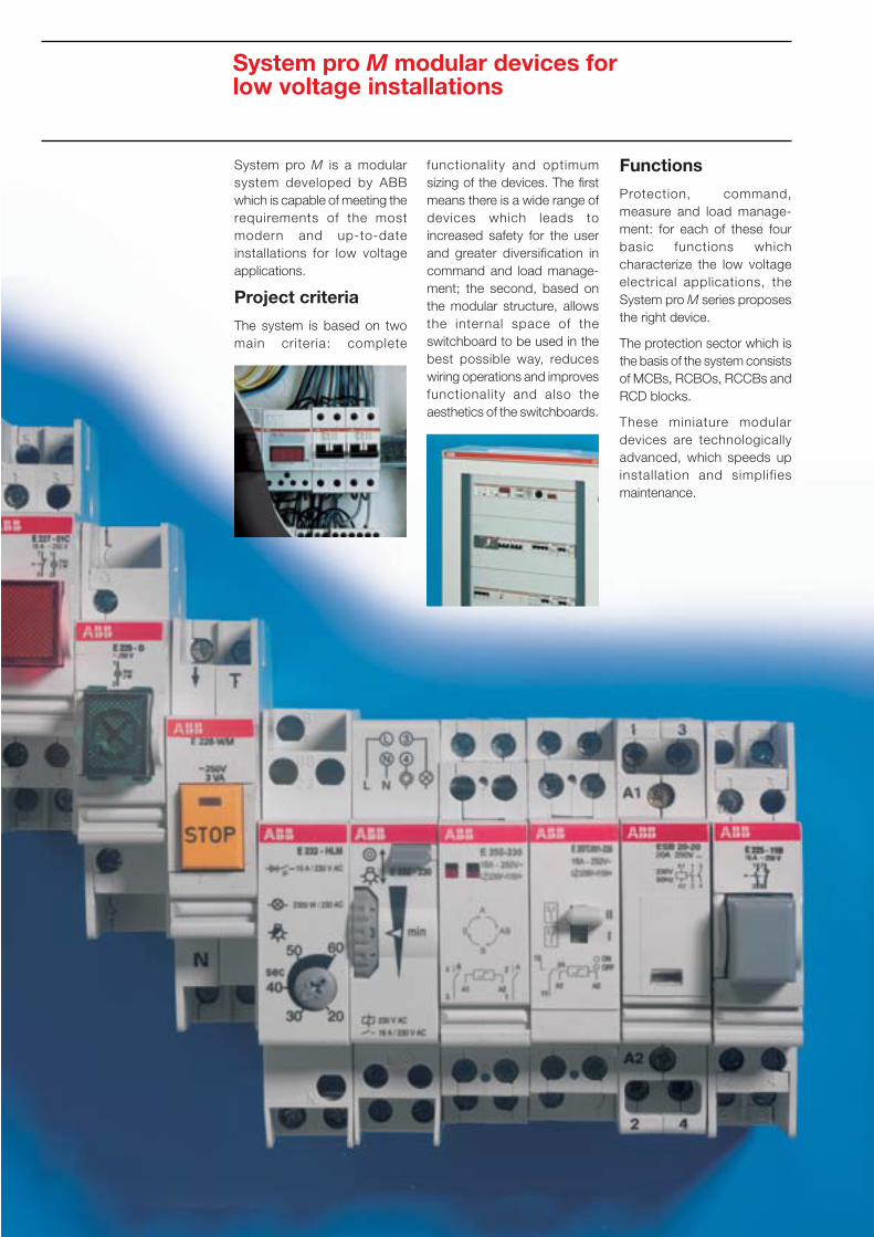
Protection, command,measure and load manage-ment: for each of these fourbasic functions whichcharacterize the low voltageelectrical applications, theSystem pro M series proposesthe right device.
The protection sector which isthe basis of the system consistsof MCBs, RCBOs, RCCBs andRCD blocks.
These miniature modulardevices are technologicallyadvanced, which speeds upinstallation and simplif iesmaintenance.
System pro M is a modularsystem developed by ABBwhich is capable of meeting therequirements of the mostmodern and up-to-dateinstallations for low voltageapplications.
Project criteria
The system is based on twomain criteria: complete
functionality and optimumsizing of the devices. The firstmeans there is a wide range ofdevices which leads toincreased safety for the userand greater diversification incommand and load manage-ment; the second, based onthe modular structure, allowsthe internal space of theswitchboard to be used in thebest possible way, reduceswiring operations and improvesfunctionality and also theaesthetics of the switchboards.
0/5ABB SACE
System pro M modular devices forlow voltage installations
Standards andcertification
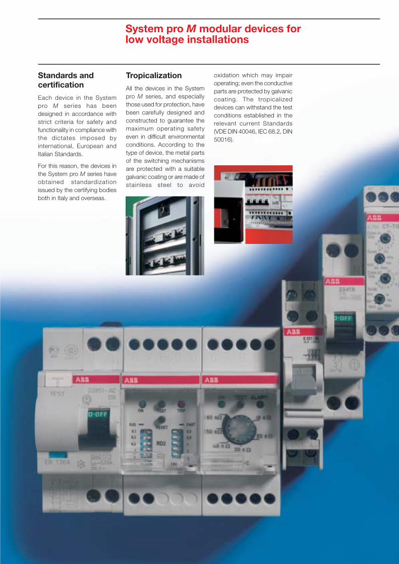
Each device in the Systempro M series has beendesigned in accordance withstrict criteria for safety andfunctionality in compliance withthe dictates imposed byinternational, European andItalian Standards.
For this reason, the devices inthe System pro M series haveobtained standardizationissued by the certifying bodiesboth in Italy and overseas.
Tropicalization
All the devices in the Systempro M series, and especiallythose used for protection, havebeen carefully designed andconstructed to guarantee themaximum operating safetyeven in difficult environmentalconditions. According to thetype of device, the metal partsof the switching mechanismsare protected with a suitablegalvanic coating or are made ofstainless steel to avoid
oxidation which may impairoperating; even the conductiveparts are protected by galvaniccoating. The tropicalizeddevices can withstand the testconditions established in therelevant current Standards(VDE DIN 40046, IEC 68.2, DIN50016).

0/6 ABB SACE
Unifix cabling system
Unifix cabling system:the ideal complement for the System pro M range
Unifix is the ABB cabling system which makes the work of installersand switchboard builders easier: with its standard connectors, Unifixeffects simple, quick and safe wiring of System pro M modulardevices and SACE Isomax S1 and S2 and Tmax T1…T3 moulded-case circuit-breakers in ArTu® switchboards and ABB consumerunits.
For this reason, it is the ideal solution for using pro M modularproducts to best advantage and exploiting the fact that ABB productsfor low voltage applications can be perfectly integrated whilst at thesame time guaranteeing safety and full compliance with Standards.
The system consists of three series H, L and SL. Each one issuitable for specific applications both for the installation of devicesand installation in switchboards. In detail:
- the H series, intended for more demanding applications, is usedfor wiring SACE Isomax S1 and S2 and Tmax T1…T3 moulded-case circuit-breakers and System pro M modular devices in ArTu®
switchboards (rated currents up to 400A and short-circuit currentsup to 50kA);
- the L series is the universal solution for wiring System pro M mo-dular devices in ArTu® switchboards and polycarbonate consumerunits (rated currents up to 100A and short-circuit currents up to25kA);
- the SL series is the ideal easy and cheap solution for wiring bipolarmodular devices in consumer units (rated currents up to 40A andshort-circuit currents up to 10kA).
ONE SYSTEM, MANYADVANTAGESConsiderable reduction in wiringtimes: by using rigid lock connec-tors which are standardized for thedifferent types of device, eachdevice does not have to beconnected using cable
Greater standardization of lowvoltage switchboards: the rigidconnectors enable the results ofthe type tests (overheating andshort-circuit) effected by ABB to beextended also on input wiring ofdevices.
A more advanced and, at thesame time, cheaper technicalsolution compared with traditionalwiring. This is made possible bycutting down on materials (wiresand wire terminals) and spacerequired, thus affecting operatingtimes
Can be used on all ABB standarddevices, without modifying oradding accessories and withoutusing special equipment
Adjustable pitch: Unifix usesadjustable pitch unlike traditionalwiring harnesses; in this way,circuit-breakers with different po-larity can be placed in the same rowas well as auxiliary devices
voltage products, both modular and moulded-case devices,switchboards or insulating consumer units, ensures that all devicesand accessories can be quickly selected and installed.
12345
N.B. The Unifix cabling system can be used with ABB SACE devices only.
Special features
The main feature of Unifix lies with the possibility of combining differenttypes of circuits (one-phase/three-phase/auxiliary) in a single module.Pre-wiring can be effected at the workbench and installed in theswitchboard subsequently, with no limits to the type or combinationof devices which can be installed.
Unifix has adjustable pitch which replaces traditional wiring harnesseswhich means that circuit-breakers with different polarities can beplaced in the same row as well as auxiliary modular devices.
The fact that Unifix integrates perfectly with the different ABB low

1/1ABB SACE
1
MCBs
Contents
General information .............................................................................................................. 1/2
General characteristics and breaking capacities ..............................................................1/4
S 9.. range .............................................................................................................................. 1/7
S 2.. range ............................................................................................................................1/21
S 290 range ..........................................................................................................................1/53
S 500 range ..........................................................................................................................1/61
S 700 range ..........................................................................................................................1/73
ABB SACE

1/2 ABB SACE
1
MCBsGeneral information
National and internationalStandards establish the basicrequirements of these circuit-breakers, but the task of cor-rectly developing the variouscharacteristics of a circuit-breaker so that it is really relia-ble depends on the experienceof the manufacturer.For this reason, the reliability andversatility of ABB’s MCBs is theresult of perfectly harmonizingdifferent parameters whichdefine the technical andinstallation characteristicsincluding:
2/2 ABB SACE
Designed to protect againstoverload and short-circuit,MCBs are vitally important de-vices for reliable and safe ope-rating of installations.
• tripping characteristics (B, C,D, K, Z) which are suitable forthe different applications;
• limiting the specific let-through energy ∫i2(t)dt down-stream of the circuit-breakersin the event of short-circuiting, thereby avoidingdamage to cables andequipment;
• limiting the peak current Ip;• current rated value In;
1

1/3ABB SACE
1
VEDI TABELLONE(per motivi tecnici di fotolito queste pagine bian-che non si possono ne si devono eliminare)
MCBsGeneral information
• front breaking capacitymarking to IEC EN 60898 andside breaking capacitymarking to IEC EN 60947-2;
• wide range of auxil iaryelements (auxiliary contacts,signal contacts, undervoltagereleases, shunt trips, me-chanical interlocks, etc.);
• life cycle guaranteed by alarge number of electric andmechanical operations;
• adequate resistance tobumps and vibrations;
• suitable protective criteria(tropicalization) for harsh en-vironmental conditions inwhich the equipment may beused.

NOTEAll S 2.. range circuit-breakers have twin breaking powermarkings:- front Icn according to IEC EN 60898- side Icu/Ics according to IEC EN 60947-2
depending on the rated current.The S 2.. curves K, Z breaking capacity on the front refers toVDE 0660.
1/4
MCBsGeneral characteristics and breaking capacities
Series
Characteristics
Rated current [A]
Breaking capacity [kA]
Reference Standards n° poles Ue [V]
IEC 23-3/EN 60898 Icn 230/400
IEC EN 60947-2 Icu 1 127alternating current 230
1P+N 127
230
2 230
400
3, 4 230
400
3 500
690
Ics 1 127
230
1P+N 127
230
2 230
400
3, 4 230
400
3 500
690
IEC EN 60947-2 Icu 1 60direct current 125
220
1P+N 125
2 125
250
440
3, 4 750
Ics 1 60
125
220
1P+N 125
2 125
250
440
3, 4 750
1
S 931 N S 941 N S 951 N S 971 N S 240 S 250
C B, C B, C B, C C B, C K
2 ≤In ≤40 2 ≤In ≤40 2 ≤In ≤40 2 ≤In ≤40 6 ≤In ≤40 0.5 ≤In ≤63 0.5 ≤In ≤63
3 4.5 6 10 4.5 6 6 a)
10 30 30
6 10 10
6 10 15 25 10 30 30
4.5 6 10 15 6 10 10
7.5 20 20
7.5 10 10
10 20 20
7.5 10 10
10 22.75 22.75
6 7.5 7.5
4.5 6 10 15 10 22.75 22.75
3 4.5 6 10 6 7.5 7.5
7.5 15 15
5.6 7.5 7.5
10 15 15
5.6 7.5 7.5
6 10 15 15 6 10 10
6 10 15 15
6 10 10
6 10 15 15 6 10 10
6 10 15 15
6 10 10
1/6 ABB SACE
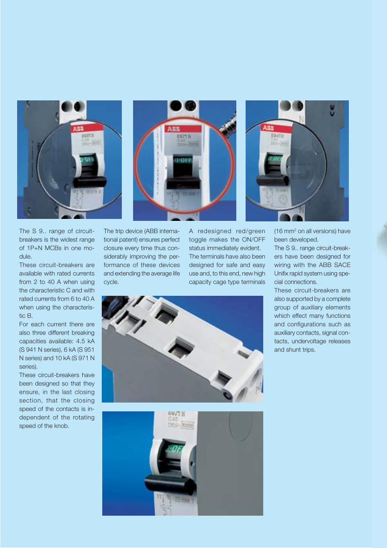
The S 9.. range of circuit-breakers is the widest rangeof 1P+N MCBs in one mo-dule.These circuit-breakers areavailable with rated currentsfrom 2 to 40 A when usingthe characteristic C and withrated currents from 6 to 40 Awhen using the characteris-tic B.For each current there arealso three different breakingcapacities available: 4.5 kA(S 941 N series), 6 kA (S 951N series) and 10 kA (S 971 Nseries).These circuit-breakers havebeen designed so that theyensure, in the last closingsection, that the closingspeed of the contacts is in-dependent of the rotatingspeed of the knob.
(16 mm2 on all versions) havebeen developed.The S 9.. range circuit-break-ers have been designed forwiring with the ABB SACEUnifix rapid system using spe-cial connections.These circuit-breakers arealso supported by a completegroup of auxiliary elementswhich effect many functionsand configurations such asauxiliary contacts, signal con-tacts, undervoltage releasesand shunt trips.
The trip device (ABB interna-tional patent) ensures perfectclosure every time thus con-siderably improving the per-formance of these devicesand extending the average lifecycle.
A redesigned red/greentoggle makes the ON/OFFstatus immediately evident.The terminals have also beendesigned for safe and easyuse and, to this end, new highcapacity cage type terminals

1/7ABB SACE
1
S 9.. range
Contents
Technical characteristics ......................................................................................................... 1/8
Order information
S 931 N series ......................................................................................................................1/10
S 941 N series ...................................................................................................................... 1/11
S 951 N series ......................................................................................................................1/12
S 971 N series ......................................................................................................................1/13
Auxiliary elements
Shunt trips .............................................................................................................................1/16
Auxiliary/signal contacts ........................................................................................................1/17
Undervoltage releases ..........................................................................................................1/18
Accessories
Busbars ................................................................................................................................. 1/19

1/8 ABB SACE
1
S 9.. rangeTechnical characteristics
S 931 NStandards IEC EN 60898, IEC EN 60947-2Rated current In [A] 2≤In≤40Poles 1P+NRated voltage Ue [V] 230Insulation voltage Ui [V] 500Max. operating a.c. [V] 250voltage Ub max. d.c. 1P [V] -
d.c. 1P+N [V] -Min. operating voltage Ub min. [V] 12 V a.c.- 12 V d.c.Rated frequency [Hz] 50…60
Rated breaking capacity Icn [A] 3000IEC EN 60898Rated breaking capacity ultimate Icu [kA] 4.5acc. to IEC EN 60947-2 1P+N - 230 V service Ics [kA] 4.5Voltage withstanding capacity impulse (1.2/50) Uimp [kV] 5Dielectric test voltage at ind. freq. for 1 min. [kV] 3
Thermomagnetic release B: 3 In≤Im≤5 Incharacteristic C: 5 In≤Im≤10 In
D: 10 In≤Im≤20 In
K: 8 In≤Im≤14 InZ: 2 In≤Im≤3 In
Toggle black sealable in ON-OFF positionElectrical life 10000Mechanical life 20000
Protection degree housing IP4X/IPXXD (except on terminals)terminals IP2X/IPXXB
Mechanical shock resistance minimum 30 g - 2 shocks - duration 13 msResistance to vibrations acc. to DIN IEC 68-2-6 6 g - 20 cycles at frequency 5…150…5 Hz with load 0.8 InTropicalization humid heat [°C/RH] 28 cycles with 55/95…100acc. to DIN 40046 IEC 68-2 const. climatic cond. [°C/RH] 23/83-40/93-55/20
var. climatic cond. [°C/RH] 25/95-40/95Thermal releaser calibration temperature [°C] 30Ambient temperature (with daily average ≤+35°C) [°C] -25…+55Storage temperature [°C] -40…+70Terminal size upper/lower per cable [mm2] 16/16Tightening torque [N*m] 1.2Mounting on rail EN 60715 (35 mm) by means of rapid fixing devicePole dimensions HxDxW [mm] 83x68x17.8Pole weight [g] 110

1/9ABB SACE
1
S 941 N S 951 N S 971 NIEC EN 60898, IEC EN 60947-2
2≤In≤401P+N23050025460
12512 V a.c.-12 V d.c.
50…60
4500 6000 10000
4.5\6 10 154.5 6 10
2.5 2.5 2.5
black sealable in ON-OFF position1000020000
IP4XIP2X
minimum 30 g - 2 shocks - duration 13 ms5 g - 20 cycles at frequency 5…150…5 Hz with load 0.8 In
28 cycles with 55/95…10023/83-40/93-55/20
25/95-40/9530
-25…+55-40…+70
16/161.2
on rail EN 60715 (35 mm) by means of rapid fixing device83x68x17.8
110
S 9.. rangeTechnical characteristics
1/10 ABB SACE
1
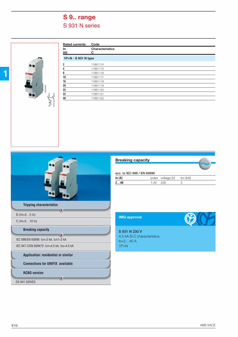
Breaking capacity
acc. to IEC 898 / EN 60898
In [A] poles voltage [V] Icn [kA]
2...40 1+N 230 3
S 9.. rangeS 931 N series
Rated currents CodeIn Characteristics[A] C
1P+N - S 931 N type
2 11861114
4 11861115
6 11861116
10 11861117
16 11861118
20 11861119
25 11861120
32 11861121
40 11861122
IMQ approval
S 931 N 230 V4.5 kA B-C characteristicsIn=2…40 A1P+N
B (Im=3…5 In)
C (Im=5…10 In)
Tripping characteristics
Application: residential or similar
Connections for UNIFIX available
RCBO version
DS 941 SERIES
TEP
M00
60
IEC 898/EN 60898: Icn=3 kA, Icn1=3 kA
IEC 947-2/EN 609472: Icn=4.5 kA, Ics=4.5 kA
Bresking capacity

1/11ABB SACE
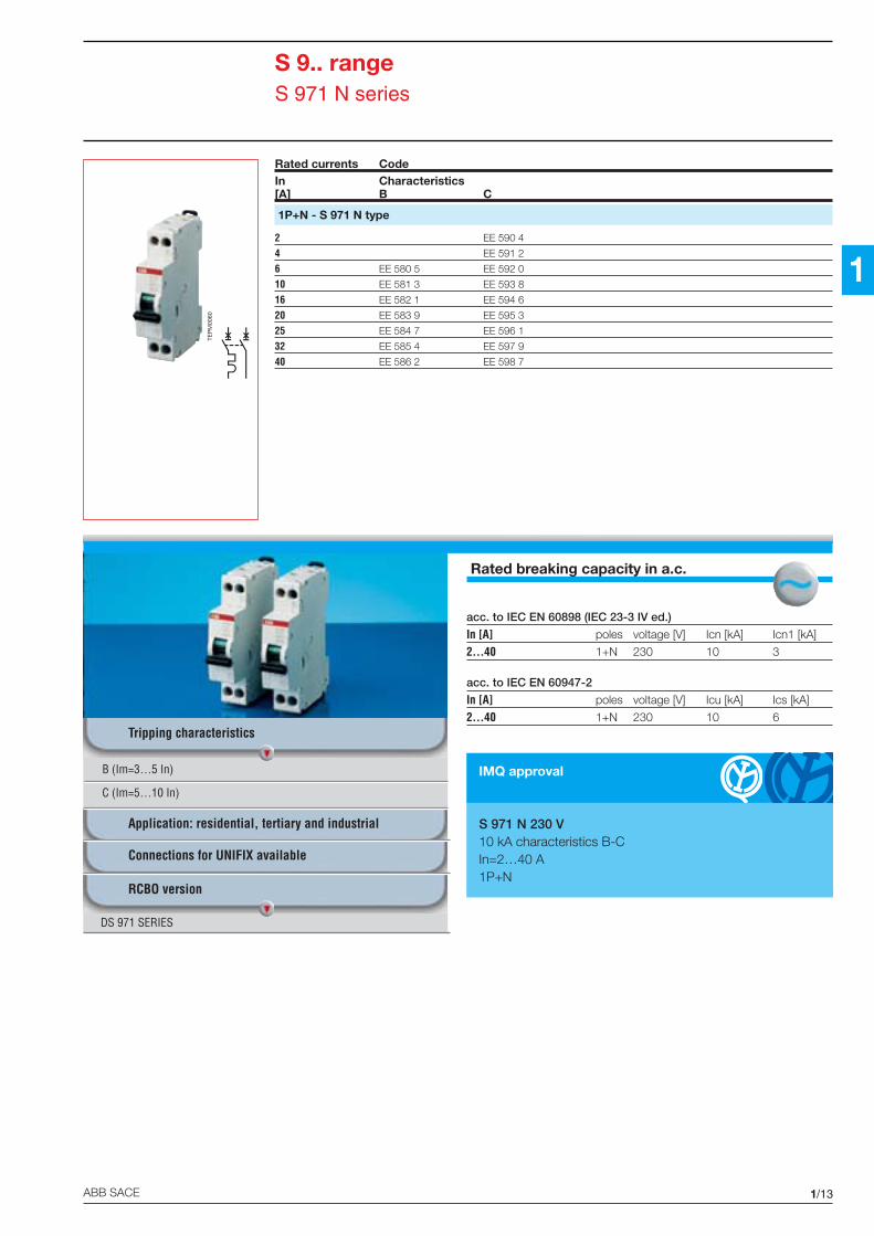
1
Rated breaking capacity in a.c.
acc. to IEC EN 60898 (IEC 23-3 IV ed.)
In [A] poles voltage [V] Icn [kA] Icn1 [kA]
2...40 1+N 230 4.5 3
acc. to IEC EN 60947-2
In [A] poles voltage [V] Icu [kA] Ics [kA]
2...40 1+N 230 6 4.5
S 9.. rangeS 941 N series
Rated currents CodeIn Characteristics[A] B C
1P+N - S 941 N type
2 EE 550 8
4 EE 551 6
6 EE 540 9 EE 552 4
10 EE 541 7 EE 553 2
16 EE 542 5 EE 554 0
20 EE 543 3 EE 555 7
25 EE 544 1 EE 556 5
32 EE 545 8 EE 557 3
40 EE 546 6 EE 558 1
IMQ approval
S 941 N 230 V4.5 kA characteristics B-CIn=2…40 A1P+N
B (Im=3…5 In)
C (Im=5…10 In)
Tripping characteristics
Application: residential and tertiary
Connections for UNIFIX available
RCBO version
DS 941 SERIES
TEP
M00
60

1/12 ABB SACE
1
Rated breaking capacity in a.c.
acc. to IEC EN 60898 (IEC 23-3 IV ed.)
In [A] poles voltage [V] Icn [kA] Icn1 [kA]
2...40 1+N 230 6 3
acc. to IEC EN 60947-2
In [A] poles voltage [V] Icu [kA] Ics [kA]
2...40 1+N 230 10 6
S 9.. rangeS 951 N series
IMQ approval
S 951 N 230 V6 kA characteristics B-CIn=2…40 A1P+N
Rated currents CodeIn Characteristics[A] B C
1P+N - S 951 N type
2 EE 570 6
4 EE 571 4
6 EE 560 7 EE 572 2
10 EE 561 5 EE 573 0
16 EE 562 3 EE 574 8
20 EE 563 1 EE 575 5
25 EE 564 9 EE 576 3
32 EE 565 6 EE 577 1
40 EE 566 4 EE 578 9
B (Im=3…5 In)
C (Im=5…10 In)
Tripping characteristics
Application: residential, tertiary and industrial
Connections for UNIFIX available
RCBO version
DS 951 SERIES
TEP
M00
60
1/13ABB SACE
1
Rated breaking capacity in a.c.
acc. to IEC EN 60898 (IEC 23-3 IV ed.)
In [A] poles voltage [V] Icn [kA] Icn1 [kA]
2...40 1+N 230 10 3
acc. to IEC EN 60947-2
In [A] poles voltage [V] Icu [kA] Ics [kA]
2...40 1+N 230 10 6
S 9.. rangeS 971 N series
Rated currents CodeIn Characteristics[A] B C
1P+N - S 971 N type
2 EE 590 4
4 EE 591 2
6 EE 580 5 EE 592 0
10 EE 581 3 EE 593 8
16 EE 582 1 EE 594 6
20 EE 583 9 EE 595 3
25 EE 584 7 EE 596 1
32 EE 585 4 EE 597 9
40 EE 586 2 EE 598 7
IMQ approval
S 971 N 230 V10 kA characteristics B-CIn=2…40 A1P+N
B (Im=3…5 In)
C (Im=5…10 In)
Tripping characteristics
Application: residential, tertiary and industrial
Connections for UNIFIX available
RCBO version
DS 971 SERIES
TEP
M00
60

1/14 ABB SACE
1
S 9.. rangeAuxiliary elements
For the S 9.. circuit-breakersundervoltage releases and con-tacts (auxiliary and signal) areavailable.
The accessories are installed indifferent positions: shunt tripsand undervoltage releases areinstalled to the left of the circuit-breaker whereas the contacts(signal and auxiliary) are installedto the right.
These elements provide addi-tional functions and are allcoupled directly to the circuit-
breaker without the use of othercomponents such as pins orclips.
The auxiliary contact is equippedwith a green indicator whichshows the position of the circuit-breaker (when the circuit-breaker is in the “open” positionthe indicator protrudes). Thesame indicator also enables atest of the auxiliary circuit.
The signal contact is equippedwith a yellow indicator whichprotrudes out when the circuit-breaker trips. This indicator alsoresets manually the signal circuit(RESET).
The signal contact is alsoequipped with a test button(TEST) which tests the signal cir-cuit contact irrespective of thestate of the MCB.
On each circuit-breaker in theS 9.. range, up to a maximumof 3 contacts can be used (thesignal contact, if necessary,should be installed directly onthe circuit-breaker and only onecan be used).
Shunt trips and undervoltagereleases are equipped with aprotruding red indicator whichshows opening of the circuit-breaker (if caused by the re-lease).
There are also two versions ofthe undervoltage releasesequipped with a tripping delayof 100 ms (S 9-V24CA andS 9-V24CC types), which pre-vents undesirable trippingcaused by microinterruption ordrop in the network voltagewhich lasts less than 100 ms.
The procedures for accesso-rizing are shown in the figure.
TEP
M04
24

1/15ABB SACE
1
MCBsS 941 NS 951 NS 971 N1P+N
S9-XAUXILIARYCONTACT
S9-XAUXILIARYCONTACT
S9-TSHUNT TRIP
S9-VUNDERVOLTAGE
RELEASE
S9-XAUXILIARYCONTACT
S9-SSIGNAL
CONTACT
Examples of combinations of S 941N, S 951 N and S 971 N circuit-breakers with auxiliary elements (maximum configurations)
S 9.. rangeAuxiliary elements

1/16 ABB SACE
1
S 9.. rangeAuxiliary elements
Shunt trips
They are used to trigger remote opening of the MCBs.
They have an integrated signal contact that indicates the contact position of the breaker they areconnected to.
Code Type Description
for S 941 N, S 951 N and S 971 N series
EE 619 1 S9-T24 12-24 V a.c./d.c. shunt trip
EE 620 9 S9-T130 48-130 V a.c./48-60 V d.c. shunt trip
EE 621 7 S9-T415 220-415 V a.c./110-250 V d.c. shunt trip
Technical characteristicsType S9-T24 S9-T130 S9-T415
Voltage [V] a.c. 12…24 48…130 220…415
[V] d.c. 12…24 48…60 110…250
Frequency [V] 50…60
Consumptionon release [VA] 20 VA (12 V a.c.) 22 VA (48 V a.c.) 40 VA (220 V a.c.)
90 VA (24 V a.c.) 200 VA (130 V a.c.) 130 VA (415 V a.c.)20 VA (12 V d.c.) 22 VA (48 V d.c.) 10 VA (110 V d.c.)90 VA (24 V d.c.) 20 VA (250 V d.c.)
Terminals [mm2] 2x1.5
1
2
C1
C2
,
Montaggio solo a sinistra
S9-T24, S9-T130, S9-T415
TEP
M04
21
OE
PM
0285
OE
PM
0286
Installation only on left

1/17ABB SACE
1
S 9.. rangeAuxiliary elements
Auxiliary/signal contacts
The auxiliary contact indicates the position of the circuit-breaker contact. When the position of thecontacts change, whether manually or automatically, they indicate their status.The signal contact indicates the position of the circuit-breaker contacts after automatic release of thecircuit-breaker caused by overload or short-circuit. For manual operation, it does not trip. The signalcontacts in the S 941 N, S 951 N and S 971 N series breakers are equipped with a test button on thefront of the accessory which simulates the functions without acting directly on the circuit-breaker.
Code Type Description
For S 941 N, S 951 N ed S 971 N series
EE 610 0 S9-X auxiliary contact 1NO + 1NC (1/2 module)
EE 611 8 S9-S signal contact 1NO + 1NC (1/2 module)
TEP
M04
22
OE
PM
0288
Automaticopening
Manualopening

1/18 ABB SACE
1
S 9.. rangeAuxiliary elements
Undervoltage releases
These are used and/or to effect a positive safety emergency stop and/or to protect the load in theevent of a voltage drop (threshold between 70% and 35% of its rated value). If used for an emergencystop, they cause undesirable tripping also for temporary microinterruptions of the voltage for a fewdozen milliseconds. ABB also makes DDA AE blocks which combine the residual current functionand the positive safety emergency stop without the use of an auxiliary energy source (battery) andauxiliary circuits. The DDA AE blocks perform the functions of an undervoltage release but withoutthe disadvantages of an undesirable tripping .
Code Type Description
for S 941 N, S 951 N, S 971 N series
EE 612 6 S9-V24CA 24 V a.c. undervoltage release
EE 613 4 S9-V24CC 24 V d.c. undervoltage release
EE 614 2 S9-V48CA 48 V a.c. undervoltage release
EE 615 9 S9-V48CC 48 V d.c. undervoltage release
EE 616 7 S9-V230CA 230 V a.c. undervoltage release
TEP
M04
23
OE
PM
0286
OE
PM
0289
Technical characteristicsType S9-V24CA S9-V24CC S9-V48CA S9-V48CC S9-V230CA
Voltage [V] a.c. 24 – 48 – 230
[V] d.c. – 24 – 48 –
Frequency [Hz] 50…60
Consumption on release [VA] 6 2 4.3 2 4.3
Terminals [mm2] 2x1.5

1/19ABB SACE
1
S 9.. rangeAccessories
Busbars
Available in versions with 4 and 12 modules, these are made of a copper conductor and an insulatingplastic housing. For all of the different types of busbars, the maximum capacity is 60 A, whilst thecopper cross-section is 10 mm2.
Code Type Description
Per serie S 9.. e DS 9..
EA 095 8 BCP 1P - 12 mod. pin type busbar 1P – 12 modules
EA 096 6 BCP N - 12 mod. pin type busbar 1P(N) - 12 modules
EA 097 4 BCP 1P - 4 mod. pin type busbar 1P - 4 modules
EA 098 2 BCP N - 4 mod. pin type busbar 1P(N) - 4 modules
EA 099 0 BCP 2P - 12 mod. pin type busbar 2P - 12 modules
EA 100 6 BCP 3P - 12 mod. pin type busbar 3P - 12 modules
EA 101 4 BCP 4P - 12 mod. pin type busbar 4P - 12 modules
EA 102 2 MR 25-15 pin type terminal 25 mm2 - 15 mm
EA 103 0 MR 25-30 pin type terminal 25 mm2 - 30 mm
OE
PM
0288
Example of application with S 9.. MCBs

1/20 ABB SACE
The S 2.. range consists of 6series of circuit-breakers whichare capable of meeting all theprotection requirements of cir-cuits up to 63 A, from domesticto industrial applications.
The S 240 - S 250 - S 270 -S 280 series are available in 1P-2P-3P-4P versions withthermomagnetic releases in C(S 240 - S 250 - S 270 - S 280),B (S 250 - S 270 - S 280),D (S 270 - S 280), K (S 270 -S 280) and Z characteristic(S 280).
These 4 series have the follo-wing breaking capacities accord-ing to IEC 898/EN 60898:4.5 kA for the S 240 series,6 kA for the S 250 series, 10 kAfor the S 270 series and 25 kAfor the S 280 (10A≤In≤25A)series.
Recently the S 280 series hasbeen enlarged with the new80 A and 100 A rated currentversions (one pole, one mo-dule) available in B and C cha-racteristics, 6 kA breaking ca-pacity according to IEC 898/EN 60898 Standard and35 mm2 size of the terminals.
The range also includes theS 280 UC series which protectsdirect current circuits with highvoltages, at which standardcircuit-breakers cannot opera-te.
The M 280 series has recentlybeen developed and consistsof 1P-2P-3P-4P circuit-brea-kers with magnetic only re-leases which are particularlysuitable for protecting motorswith high start-up currents.
All circuit-breakers in the S 2..range have self-supportingmechanical parts; in thesebreakers, there is no specificmechanical constraint betweenthe case and the internal me-chanical components whichform three independent func-tional blocks; in this way, anydistortion of the case, in theevent of thermal shock, doesnot affect the correct functio-ning of the circuit-breaker.
The supply lines of the pro-tected circuits can be con-nected to either the upper orlower terminals of the circuit-breakers (reversibility of con-nections).
Another feature of the circuit-breakers in this range is thedouble terminal which enablessimultaneous connection ofcables and busbars.
All the circuit-breakers in theS 2.. range with C and B cha-racteristics have IMQ approvalwhich demonstrates the highlevel of quality achieved.
On some of the series, approvalfrom the Italian Naval Register(R.I.Na.) and the main navalcertifying bodies (see detailedindications for each series) isalso available.
TEP
M00
26TE
PM
0027
TEP
M00
28TE
PM
0029
1/21ABB SACE
1
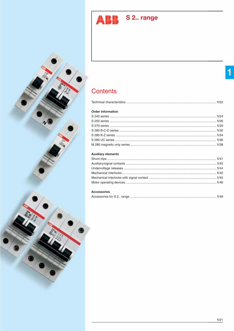
S 2.. range
Contents
Technical characteristics .......................................................................................................1/22
Order information
S 240 series ..........................................................................................................................1/24
S 250 series ..........................................................................................................................1/26
S 270 series ..........................................................................................................................1/29
S 280 B-C-D series ............................................................................................................... 1/32
S 280 K-Z series ...................................................................................................................1/34
S 280 UC series ....................................................................................................................1/36
M 280 magnetic only series .................................................................................................. 1/38
Auxiliary elements
Shunt trips ............................................................................................................................. 1/41
Auxiliary/signal contacts ........................................................................................................1/42
Undervoltage releases ..........................................................................................................1/44
Mechanical interlocks ............................................................................................................1/45
Mechanical interlocks with signal contact ............................................................................. 1/45
Motor operating devices ........................................................................................................1/46
Accessories
Accessories for S 2.. range .. ................................................................................................ 1/49

1/22 ABB SACE
1
S 2.. rangeTechnical characteristics
S 240 S 250 S 270Standards IEC EN 60898, IEC EN 60947-2Rated current In [A] 6≤In≤40 0.5≤In≤63 0.5≤In≤63
Poles 1P, 1P+N, 2P, 3P, 4PRated voltage Ue 1P [V] 230
2P, 3P, 4P [V] 230/400Insulation voltage Ui [V] 500Max. operating a.c. [V] 440voltage Ub max. d.c. 1P [V] 60 V d.c.
d.c. 2P [V] 125 V d.c.Min. operating voltage Ub min. [V] 12 V a.c.-12 V d.c.Rated frequency [Hz] 50…60
Rated breaking capacity Icn [A] 4500 6000 10000acc. to IEC EN 60898Rated breaking capacity ultimate Icu [kA] 7.5 20 25IEC EN 60947-2 2P - 230 V service Ics [kA] 7.5 15 18.7
Rated breaking capacity ultimate Icu [kA] 7.5 10 15IEC EN 60947-2 3P, 4P - 400 V service Ics [kA] 5.6 7.5 11.2Rated breaking capacity ultimate Icu [kA]IEC EN 60947-2 service Ics [kA]1P - 220 V d.c., 2P - 440 V d.c.Voltage withstanding capacityimpulse (1.2/50) Uimp [kV] 5Dielectric test voltage at ind. freq. for 1 min. [kV] 2.5
Thermomagnetic release B: 3 In≤Im≤5 In
characteristic C: 5 In≤Im≤10 In
D: 10 In≤Im≤20 In
K: 8 In≤Im≤14 In
Z: 2 In≤Im≤3 In
magnetic only: 12 In≤Im≤14 In
Toggle black sealable in ON-OFF positionElectrical life 10000Mechanical life 20000
Protection degree housing IP4Xterminals IP2X
Mechanical shock resistance minimum 30 g - 2 shocks - duration 13 msResistance to vibrations acc. to DIN IEC 68-2-6 5 g - 20 cycles at frequency 5…150…5 Hz with load 0.8 InTropicalization humid heat [°C/RH] 28 cycles with 55/95…100acc. to DIN 40046 IEC 68-2 const. climatic cond.[°C/RH] 23/83-40/93-55/20
var. climatic cond. [°C/RH] 25/95-40/95Thermal releaser calibration temperature [°C] 30 (20 for curves K, Z)Ambient temperature (with daily average ≤+35 °C) [°C] -25…+55Storage temperature [°C] -40…+70Terminal size upper/lower per cable [mm2] cage type 25/25Tightening torque [N*m] 2Mounting on rail EN 60715 (35 mm) by means of rapid fixing devicePole dimensions HxDxW [mm] 90x68x17.5Pole weight [g] 125Possibility of connection to motor operating device

1/23ABB SACE
1
S 280 S 280 UC M 280IEC EN 60898, IEC EN 60947-2 IEC EN 60947-2 IEC EN 60947-2
0.5≤In≤2 32≤In≤40 3≤In≤8 80≤In≤100 0.5≤In≤40 50≤In≤63 0.5≤In≤1.6 32≤In≤40 2.5≤In≤6.310≤In≤25 50≤In≤63 10≤In≤25 50≤In≤63
1P, 2P, 3P, 4P 1P, 2P 1P, 2P, 3P, 4P230 220 V d.c. 230
230/400 440 V d.c. 230/400
60 V d.c. 220 V d.c. 60 V d.c.125 V d.c. 440 V d.c. 125 V d.c.
50…60 50…60 50…60
25000 15000 10000 6000
40 30 25 10 40 30 2530 22.5 18.7 10 30 22.5 18.75
25 20 15 6 25 20 1512.5 10 11.2 6 12.5 10 7.5
6 4.56 4.5
52.5
black sealable in ON-OFF position10000 4000 10000 1000020000 10000 20000 20000
IP4X IP4X IP4XIP2X IP2X IP2X
minimum 30 g - 2 shocks - duration 13 ms5 g - 20 cycles at frequency 5…150…5 Hz with load 0.8 In
28 cycles with 55/95…100 28 cycles with 55/95…100 28 cycles with 55/95…10023/83-40/93-55/20 23/83-40/93-55/20 23/83-40/93-55/20
25/95-40/95 25/95-40/95 25/95-40/9530 (20 for curves K, Z) 30 (20 for curves K, Z)
-25…+55 -25…+55 -25…+55-40…+70 -40…+70 -40…+70
cage type 25/25 cage type 35/35 cage type 25/25 cage type 25/252 2.5 2 2
on rail EN 60715 (35 mm) by means of rapid fixing device90x68x17.5 – 90x68x17.5 90x68x17.5
140 160 140 140 –
S 2.. rangeTechnical characteristics
1/24 ABB SACE
1
TEP
M00
34
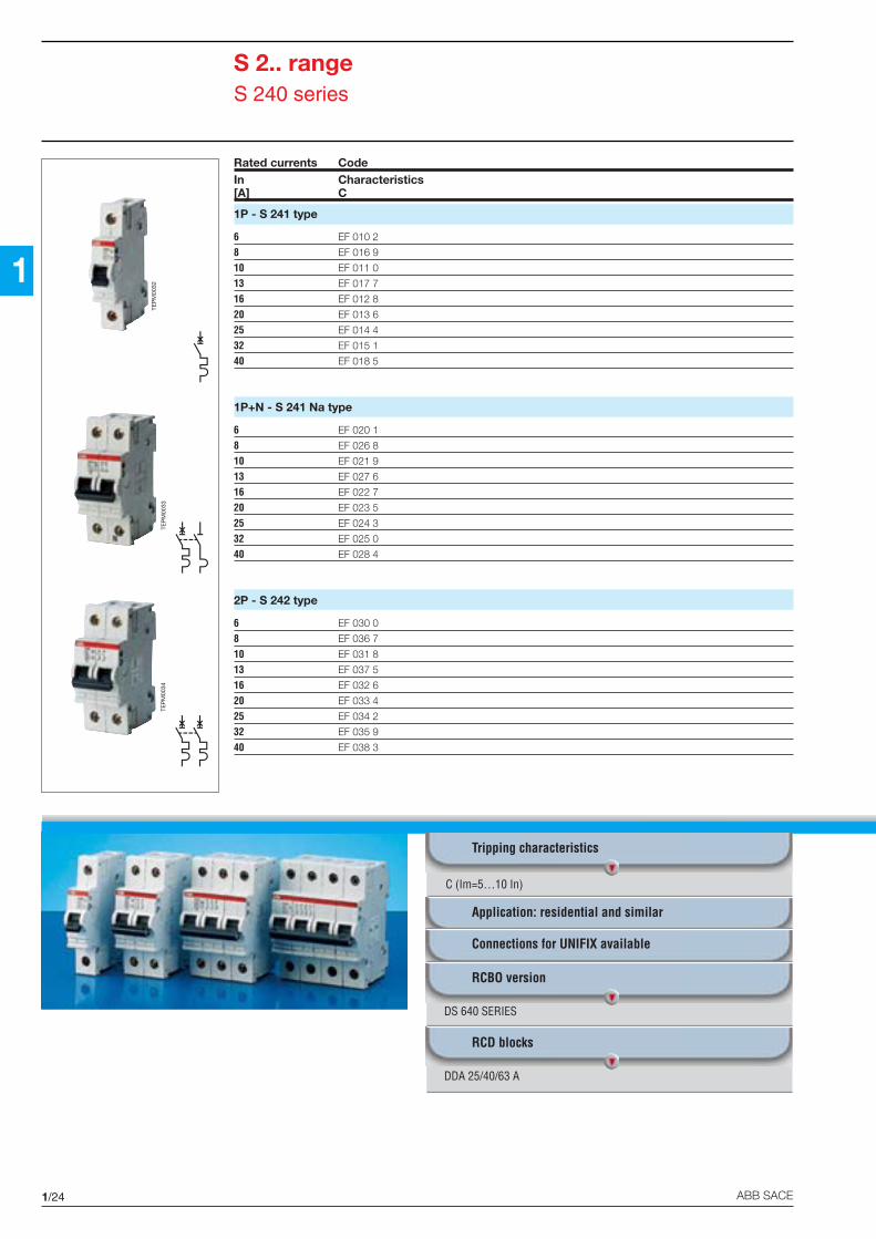
S 2.. rangeS 240 series
Rated currents CodeIn Characteristics[A] C
1P - S 241 type
6 EF 010 2
8 EF 016 9
10 EF 011 0
13 EF 017 7
16 EF 012 8
20 EF 013 6
25 EF 014 4
32 EF 015 1
40 EF 018 5
1P+N - S 241 Na type
6 EF 020 1
8 EF 026 8
10 EF 021 9
13 EF 027 6
16 EF 022 7
20 EF 023 5
25 EF 024 3
32 EF 025 0
40 EF 028 4
2P - S 242 type
6 EF 030 0
8 EF 036 7
10 EF 031 8
13 EF 037 5
16 EF 032 6
20 EF 033 4
25 EF 034 2
32 EF 035 9
40 EF 038 3
C (Im=5…10 In)
Tripping characteristics
Application: residential and similar
Connections for UNIFIX available
RCBO version
DS 640 SERIES
RCD blocks
DDA 25/40/63 A
TEP
M00
32
TEP
M00
33
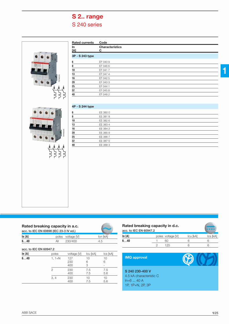
1/25ABB SACE
1
Rated breaking capacity in a.c.acc. to IEC EN 60898 (IEC 23-3 IV ed.)
In [A] poles voltage [V] Icn [kA]
6...40 All 230/400 4.5
acc. to IEC EN 60947.2
In [A] poles voltage [V] Icu [kA] Ics [kA]
6...40 1, 1+N 127 10 10230 6 6400 3 -
2 230 7.5 7.5400 7.5 5.6
3, 4 230 10 10400 7.5 5.6
Rated breaking capacity in d.c.acc. to IEC EN 60947.2
In [A] poles voltage [V] Icu [kA] Ics [kA]
6...40 1 60 6 6
2 125 6 6
Rated currents CodeIn Characteristics[A] C
3P - S 243 type
6 EF 040 9
8 EF 046 6
10 EF 041 7
13 EF 047 4
16 EF 042 5
20 EF 043 3
25 EF 044 1
32 EF 045 8
40 EF 048 2
4P - S 244 type
6 EE 380 0
8 EE 381 8
10 EE 382 6
13 EE 383 4
16 EE 384 2
20 EE 385 9
25 EE 386 7
32 EE 387 5
40 EE 388 3
S 2.. rangeS 240 series
TEP
M00
35
TEP
M00
36
IMQ approval
S 240 230-400 V4.5 kA characteristic CIn=6 ... 40 A1P, 1P+N, 2P, 3P
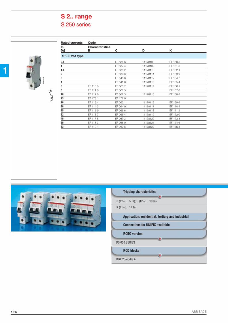
1/26 ABB SACE
1
B (Im=3…5 In); C (Im=5…10 In)
K (Im=8…14 In)
Tripping characteristics
Application: residential, tertiary and industrial
Connections for UNIFIX available
RCBO version
DS 650 SERIES
RCD blocks
DDA 25/40/63 A
S 2.. rangeS 250 series
Rated currents CodeIn Characteristics[A] B C D K
1P - S 251 type
0.5 EF 536 6 11178108 EF 160 5
1 EF 537 4 11178109 EF 161 3
1.6 EF 538 2 11178110 EF 162 1
2 EF 539 0 11178111 EF 163 9
3 EF 540 8 11178112 EF 164 7
4 EF 541 6 11178113 EF 165 4
6 EF 110 0 EF 060 7 11178114 EF 166 2
8 EF 111 8 EF 061 5 EF 167 0
10 EF 112 6 EF 062 3 11178115 EF 168 8
13 EF 176 1 EF 177 9
16 EF 113 4 EF 063 1 11178116 EF 169 6
20 EF 114 2 EF 064 9 11178117 EF 170 4
25 EF 115 9 EF 065 6 11178118 EF 171 2
32 EF 116 7 EF 066 4 11178119 EF 172 0
40 EF 117 5 EF 067 2 11178120 EF 173 8
50 EF 118 3 EF 068 0 11178121 EF 174 6
63 EF 119 1 EF 069 8 11178122 EF 175 3
TEP
M00
37

1/27ABB SACE
1
Rated breaking capacity in a.c.
acc. to IEC EN 60898 (IEC 23-3 IV ed.)
In [A] poles voltage [V] Icn [kA]
0.5...63 All 230/400 6
acc. to IEC EN 60947.2
In [A] poles voltage [V] Icu [kA] Ics[kA]
0.5...63 1, 1+N 127 30 22.75230 10 7.5400 3 -
2 230 20 15400 10 7.5
3, 4 230 20 15400 10 7.5
Rated breaking capacity in d.c.acc. to IEC EN 60947.2
In [A] poles voltage [V] Icu [kA] Ics[kA]
0.5...63 1 60 10 10
2 125 10 10
Rated currents CodeIn Characteristics[A] B C K
1P+N - S 251 Na type
0.5 EF 542 4 EF 180 3
1 EF 543 2 EF 181 1
1.6 EF 544 0 EF 182 9
2 EF 545 7 EF 183 7
3 EF 546 5 EF 184 5
4 EF 547 3 EF 185 2
6 EF 120 9 EF 070 6 EF 186 0
8 EF 121 7 EF 071 4 EF 187 8
10 EF 122 5 EF 072 2 EF 188 6
13 EF 196 9 EF 197 7
16 EF 123 3 EF 073 0 EF 189 4
20 EF 124 1 EF 074 8 EF 190 2
25 EF 125 8 EF 075 5 EF 191 0
32 EF 126 6 EF 076 3 EF 192 8
40 EF 127 4 EF 077 1 EF 193 6
50 EF 128 2 EF 078 9 EF 194 4
63 EF 129 0 EF 079 7 EF 195 1
S 2.. rangeS 250 series
TEP
M00
38
IMQ approval
S 250 230-400V6 kA characteristics B-CIn=6 ... 63 A1P, 1P+N, 2P, 3P, 4P
R.I.Na. approval
The S 252, S 253, S 254 types (B-C-K characteristics)have obtained R.I.Na. approval for naval application atvoltages of 230, 400, 440 V a.c.
UL-CSA approvals available on request
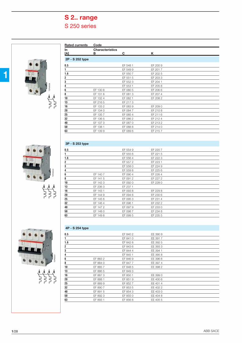
1/28 ABB SACE
1
S 2.. rangeS 250 series
Rated currents CodeIn Characteristics[A] B C K
2P - S 252 type
0.5 EF 548 1 EF 200 91 EF 549 9 EF 201 71.6 EF 550 7 EF 202 52 EF 551 5 EF 203 33 EF 552 3 EF 204 14 EF 553 1 EF 205 86 EF 130 8 EF 080 5 EF 206 68 EF 131 6 EF 081 3 EF 207 410 EF 132 4 EF 082 1 EF 208 213 EF 216 5 EF 217 316 EF 133 2 EF 083 9 EF 209 020 EF 134 0 EF 084 7 EF 210 825 EF 135 7 EF 085 4 EF 211 632 EF 136 5 EF 086 2 EF 212 440 EF 137 3 EF 087 0 EF 213 250 EF 138 1 EF 088 8 EF 214 063 EF 139 9 EF 089 6 EF 215 7
3P - S 253 type
0.5 EF 554 9 EF 220 71 EF 555 6 EF 221 51.6 EF 556 4 EF 222 32 EF 557 2 EF 223 13 EF 558 0 EF 224 94 EF 559 8 EF 225 66 EF 140 7 EF 090 4 EF 226 48 EF 141 5 EF 091 2 EF 227 210 EF 142 3 EF 092 0 EF 228 013 EF 236 3 EF 237 116 EF 143 1 EF 093 8 EF 229 820 EF 144 9 EF 094 6 EF 230 625 EF 145 6 EF 095 3 EF 231 432 EF 146 4 EF 096 1 EF 232 240 EF 147 2 EF 097 9 EF 233 050 EF 148 0 EF 098 7 EF 234 863 EF 149 8 EF 099 5 EF 235 5
4P - S 254 type
0.5 EF 840 2 EE 390 91 EF 841 0 EE 391 71.6 EF 842 8 EE 392 52 EF 843 6 EE 393 33 EF 844 4 EE 394 14 EF 845 1 EE 395 86 EF 883 2 EF 846 9 EE 396 68 EF 884 0 EF 847 7 EE 397 410 EF 885 7 EF 848 5 EE 398 213 EF 886 5 EF 849 316 EF 887 3 EF 850 1 EE 399 020 EF 888 1 EF 851 9 EE 400 625 EF 889 9 EF 852 7 EE 401 432 EF 890 7 EF 853 5 EE 402 240 EF 891 5 EF 854 3 EE 403 050 EF 892 3 EF 855 0 EE 404 863 EF 893 1 EF 856 8 EE 405 5
TEP
M00
40TE
PM
0041
TEP
M00
38

1/29ABB SACE
1
Rated breaking capacity in a.c.
acc. to IEC EN 60898 (IEC 23-3 IV ed.)
In [A] poles voltage [V] Icn [kA]
0.5...63 All 230/400 10
acc. to IEC EN 60947.2
In [A] poles voltage [V] Icu [kA] Ics [kA]
0.5...63 1, 1+N 127 35 26.2230 15 11.2400 4 -
2 230 25 18.7400 15 11.2
3, 4 230 20 15400 15 11.2
Rated breaking capacity in d.c.acc. to IEC EN 60947.2
In [A] poles voltage [V] Icu [kA] Ics [kA]
0.5...63 1 60 10 10
2 125 10 10
S 2.. rangeS 270 series
Rated currents CodeIn Characteristics[A] B C K D
1P - S 271 type
0.5 EF 566 3 EF 360 1 EF 600 0
1 EF 567 1 EF 361 9 EF 601 8
1.6 EF 568 9 EF 362 7 EF 602 6
2 EF 569 7 EF 363 5 EF 603 4
3 EF 570 5 EF 364 3 EF 604 2
4 EF 571 3 EF 365 0 EF 605 9
6 EF 310 6 EF 260 3 EF 366 8 EF 606 7
8 EF 311 4 EF 261 1 EF 367 6 EF 607 5
10 EF 312 2 EF 262 9 EF 368 4 EF 608 3
13 EF 830 3 EF 835 2
16 EF 313 0 EF 263 7 EF 369 2 EF 609 1
20 EF 314 8 EF 264 5 EF 370 0 EF 610 9
25 EF 315 5 EF 265 2 EF 371 8 EF 611 7
32 EF 316 3 EF 266 0 EF 372 6 EF 612 5
40 EF 317 1 EF 267 8 EF 373 4 EF 613 3
50 EF 318 9 EF 268 6 EF 374 2 EF 614 1
63 EF 319 7 EF 269 4 EF 375 9 EF 615 8
IMQ approval
S 270 230-400 V10 kA characteristics B-CIn=0.5...63 A (C); In=6...63 A (B)1P, 1P+N, 2P, 3P, 4P
R.I.Na. approval
The S 272, S 273 types (B-C-K characteristics) and S 274(B-C characteristics) have obtained R.I.Na. approval fornaval application at voltages 230, 400, 440 V a.c.
TEP
M00
42
B (Im=3…5 In); C (Im=5…10 In)
D (Im=10…20 In); K (Im=8…14 In)
Tripping characteristics
Application: tertiary and industrial
Connections for UNIFIX available
RCBO version
DS 670 SERIES
RCD blocks
DDA 25/40/63 A

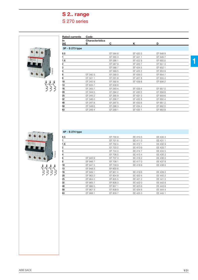
1/30 ABB SACE
1
S 2.. rangeS 270 series
Rated currents CodeIn Characteristics[A] B C K D
1P+N - S 271 Na type
0.5 EF 572 1 EF 380 9 EF 616 6
1 EF 573 9 EF 381 7 EF 617 4
1.6 EF 574 7 EF 382 5 EF 618 2
2 EF 575 4 EF 383 3 EF 619 0
3 EF 576 2 EF 384 1 EF 620 8
4 EF 577 0 EF 385 8 EF 621 6
6 EF 320 5 EF 270 2 EF 386 6 EF 622 4
8 EF 321 3 EF 271 0 EF 387 4 EF 623 2
10 EF 322 1 EF 272 8 EF 388 2 EF 624 0
13 EF 831 1 EF 836 0
16 EF 323 9 EF 273 6 EF 389 0 EF 625 7
20 EF 324 7 EF 274 4 EF 390 8 EF 626 5
25 EF 325 4 EF 275 1 EF 391 6 EF 627 3
32 EF 326 2 EF 276 9 EF 392 4 EF 628 1
40 EF 327 0 EF 277 7 EF 393 2 EF 629 9
50 EF 328 8 EF 278 5 EF 394 0 EF 630 7
63 EF 329 6 EF 279 3 EF 395 7 EF 631 5
2P - S 272 type
0.5 EF 578 8 EF 400 5 EF 632 3
1 EF 579 6 EF 401 3 EF 633 1
1.6 EF 580 4 EF 402 1 EF 634 9
2 EF 581 2 EF 403 9 EF 635 6
3 EF 582 0 EF 404 7 EF 636 4
4 EF 583 8 EF 405 4 EF 637 2
6 EF 330 4 EF 280 1 EF 406 2 EF 638 0
8 EF 331 2 EF 281 9 EF 407 0 EF 639 8
10 EF 332 0 EF 282 7 EF 408 8 EF 640 6
13 EF 832 9 EF 837 8
16 EF 333 8 EF 283 5 EF 409 6 EF 641 4
20 EF 334 6 EF 284 3 EF 410 4 EF 642 2
25 EF 335 3 EF 285 0 EF 411 2 EF 643 0
32 EF 336 1 EF 286 8 EF 412 0 EF 644 8
40 EF 337 9 EF 287 6 EF 413 2 EF 645 5
50 EF 338 7 EF 288 4 EF 414 6 EF 646 3
63 EF 339 5 EF 289 2 EF 415 3 EF 647 1
TEP
M00
43TE
PM
0044
1/31ABB SACE
1
S 2.. rangeS 270 series
Rated currents CodeIn Characteristics[A] B C K D
3P - S 273 type
0.5 EF 584 6 EF 420 3 EF 648 9
1 EF 585 3 EF 421 1 EF 649 7
1.6 EF 586 1 EF 422 9 EF 650 5
2 EF 587 9 EF 423 7 EF 651 3
3 EF 588 7 EF 424 5 EF 652 1
4 EF 589 5 EF 425 2 EF 653 9
6 EF 340 3 EF 290 0 EF 426 0 EF 654 7
8 EF 341 1 EF 291 8 EF 427 8 EF 655 4
10 EF 342 9 EF 292 6 EF 428 6 EF 656 2
13 EF 833 7 EF 838 6
16 EF 343 7 EF 293 4 EF 429 4 EF 657 0
20 EF 344 5 EF 294 2 EF 430 2 EF 658 8
25 EF 345 2 EF 295 9 EF 431 0 EF 659 6
32 EF 346 0 EF 296 7 EF 432 8 EF 660 4
40 EF 347 8 EF 297 5 EF 433 6 EF 661 2
50 EF 348 6 EF 298 3 EF 434 4 EF 662 0
63 EF 349 4 EF 299 1 EF 435 1 EF 663 8
4P - S 274 type
0.5 EF 700 8 EE 410 5 EE 430 3
1 EF 701 6 EE 411 3 EE 431 1
1.6 EF 702 4 EE 412 1 EE 432 9
2 EF 703 2 EE 413 9 EE 433 7
3 EF 704 0 EE 414 7 EE 434 5
4 EF 706 5 EE 415 4 EE 435 2
6 EF 945 9 EF 707 3 EE 416 2 EE 436 0
8 EF 946 7 EF 708 1 EE 417 0 EE 437 8
10 EF 947 5 EF 709 9 EE 418 8 EE 438 6
13 EF 948 3 EF 800 6
16 EF 949 1 EF 801 4 EE 419 6 EE 439 4
20 EF 963 2 EF 804 8 EE 420 4 EE 440 2
25 EF 964 0 EF 805 5 EE 421 2 EE 441 0
32 EF 965 7 EF 806 3 EE 422 0 EE 442 8
40 EF 966 5 EF 807 1 EE 423 8 EE 443 6
50 EF 967 3 EF 808 9 EE 424 6 EE 444 4
63 EF 968 1 EF 809 7 EE 425 3 EE 445 1
TEP
M00
45
TEP
M00
46

1/32 ABB SACE
1
TEP
M00
48
R.I.Na. approval
The S 282 and S 283 types with B-C characteristics with ratedcurrents from 0.5 to 63 A have obtained R.I.Na, Lloyd’s Register, DetNorske Veritas, Bureau Veritas approval for naval application atvoltages:- S 282 (60 V d.c./230 V a.c.)- S 283 (230-440 V a.c.)
S 2.. rangeS 280 B-C-D series
Rated currents CodeIn Characteristics[A] B C D
1P - S 281 type
6 KU 647 0 KU 657 9 KU 674 410 KU 648 8 KU 658 7 KU 810 413 KU 654 6 KU 664 516 KU 649 6 KU 659 5 KU 811 220 KU 650 4 KU 660 3 KU 812 025 KU 651 2 KU 661 1 KU 813 832 KU 652 0 KU 662 9 KU 814 640 KU 653 8 KU 663 7 KU 815 350 KU 655 3 KU 665 2 KU 817 963 KU 656 1 KU 666 0 KU 818 780 111 78645 111 78643100 111 78646 111 78644
2P - S 282 type
0.5 118 653331 118 653341.6 118 653352 118 653363 118 653374 118 653386 KU 687 6 KU 697 5 KU 819 58 118 65324 118 6534010 KU 688 4 KU 698 3 KU 820 313 KU 694 2 KU 704 916 KU 689 2 KU 699 1 KU 821 120 KU 680 0 KU 700 7 KU 822 925 KU 681 8 KU 701 5 KU 823 732 KU 682 6 KU 702 3 KU 824 540 KU 683 4 KU 703 1 KU 825 250 KU 695 9 KU 705 6 KU 827 863 KU 696 7 KU 706 4 KU 828 680 111 78651 111 78649
100 111 78652 111 78650
B (Im=3…5 In); C (Im=5…10 In)
D (Im=10…20 In)
Tripping characteristics
Application: tertiary and industrial
Connections for UNIFIX available
RCD blocks
DDA 25/40/63 A
IMQ approval
S 280 230-400 Vcharacteristics B-C25 kA In=10...25 A15 kA In=32...40 A1P, 2P, 3P, 4P
TEP
M00
47

1/33ABB SACE
1
Rated breaking capacity in a.c.acc. to IEC EN 60898In [A] poles voltage [V] Icn [kA]10...25 All 230/400 2532 – 40 All 230/400 156 – 50 – 63 All 230/400 1080 - 100 All 230/400 6
acc. to IEC EN 60947.2In [A] poles voltage [V] Icu [kA] Ics [kA]0.5...2 1 127 50 37.510...25 230 25 25
400 5 -2 230 40 30
400 25 18.753, 4 230 40 30
400 25 12.532...40 1 127 40 30
230 20 20400 4.5 -
2 230 30 22.5400 20 15
3, 4 230 30 22.5400 20 10
3-4-6-8-50-63 1 127 35 26.2230 15 11.2400 4 -
2 230 25 18.7400 15 11.2
3, 4 230 20 15400 15 11.2
80-100 1 230 6 100%400 - -
2 230 10 100%400 6 100%
3 230 10 100%400 6 100%
Rated breaking capacity in d.c.acc. to IEC EN 60947.2
In [A] poles voltage [V] Icu [kA] Ics [kA]
0.5...2 1 60 15 15
10...40 2 125 15 15
In [A] poles voltage [V] Icu [kA] Ics [kA]
3-4-6-8-50-63-80-100 1 60 10 10
2 125 10 10
Rated currents CodeIn Characteristics[A] B C D
3P - S 283 type
0.5 118 663131 118 663141.6 118 663152 118 663163 118 663174 118 663186 KU 707 2 KU 717 1 KU 829 48 118 66349 118 6632010 KU 708 0 KU 718 9 KU 830 213 KU 714 8 KU 724 716 KU 709 8 KU 719 7 KU 831 020 KU 710 6 KU 720 5 KU 832 825 KU 711 4 KU 721 3 KU 833 632 KU 712 2 KU 722 1 KU 834 440 KU 713 0 KU 723 9 KU 835 150 KU 715 5 KU 725 4 KU 837 763 KU 716 3 KU 726 2 KU 838 580 111 78657 111 78655100 111 78658 111 78656
4P - S 284 type
6 KU 727 0 KU 737 9 KU 839 310 KU 728 8 KU 738 7 KU 840 113 KU 734 6 KU 744 516 KU 729 6 KU 739 5 KU 841 920 KU 730 4 KU 740 3 KU 842 725 KU 731 2 KU 741 1 KU 843 532 KU 732 0 KU 742 9 KU 844 340 KU 733 8 KU 743 7 KU 845 050 KU 735 3 KU 745 2 KU 677 763 KU 736 1 KU 676 9 KU 678 580 160 64740 160 64724100 160 64757 160 64732
S 2.. rangeS 280 B-C-D series
TEP
M00
50
TEP
M00
49

1/34 ABB SACE
1
Rated breaking capacity in a.c.acc. to IEC EN 60947.2In [A] poles voltage [V] Icu [kA] Ics [kA]0.5...2 1 127 50 37.516...25 230 25 25
2 230 40 30400 25 18.75
3, 4 230 40 30400 25 12.5
32...40 1 127 40 30230 20 20
2 230 30 22.5400 20 15
3, 4 230 30 22.5400 20 10
3-4-6-8-10- 1 127 35 26.250-63 230 15 11.2
2 230 25 18.7400 15 11.2
3, 4 230 20 15400 15 11.2
TEP
M00
52
S 2.. rangeS 280 K-Z series
Rated currents CodeIn Characteristics[A] K Z
1P - S 281 type
0.5 KU 520 9 KU 750 21 KU 521 7 KU 751 01.6 KU 522 5 KU 752 82 KU 523 3 KU 753 63 KU 524 1 KU 754 44 KU 525 8 KU 755 16 KU 866 6 KU 756 910 KU 867 4 KU 757 713 KU 873 2 KU 886 416 KU 868 2 KU 758 520 KU 869 0 KU 759 325 KU 870 8 KU 760 132 KU 871 6 KU 761 940 KU 872 4 KU 762 750 KU 874 0 KU 763 563 KU 875 7 KU 764 3
2P - S 282 type
0.5 118 65375 KU 765 01 118 65376 KU 766 81.6 118 65377 KU 767 62 118 65378 KU 768 43 118 65379 KU 769 24 118 65380 KU 770 06 KU 856 7 KU 771 88 118 6538210 KU 857 5 KU 772 613 KU 863 3 KU 887 216 KU 858 3 KU 773 420 KU 859 1 KU 774 225 KU 860 9 KU 775 932 KU 861 7 KU 776 740 KU 862 5 KU 777 550 KU 864 1 KU 778 363 KU 865 8 KU 779 1
K (Im=8…14 In)
Z (Im=2…3 In)
Tripping characteristics
Application: industrial
Connections for UNIFIX available
RCD blocks
DDA 25/40/63 A
TEP
M00
51
1/35ABB SACE
1
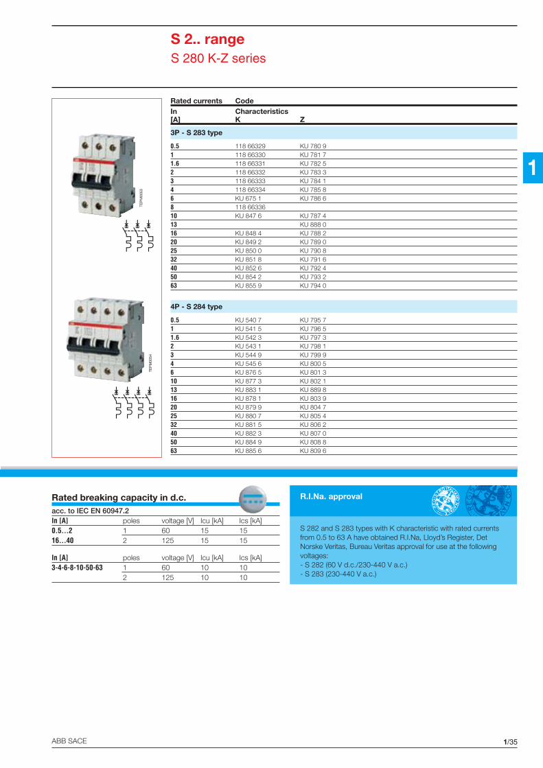
Rated currents CodeIn Characteristics[A] K Z
3P - S 283 type
0.5 118 66329 KU 780 91 118 66330 KU 781 71.6 118 66331 KU 782 52 118 66332 KU 783 33 118 66333 KU 784 14 118 66334 KU 785 86 KU 675 1 KU 786 68 118 6633610 KU 847 6 KU 787 413 KU 888 016 KU 848 4 KU 788 220 KU 849 2 KU 789 025 KU 850 0 KU 790 832 KU 851 8 KU 791 640 KU 852 6 KU 792 450 KU 854 2 KU 793 263 KU 855 9 KU 794 0
4P - S 284 type
0.5 KU 540 7 KU 795 71 KU 541 5 KU 796 51.6 KU 542 3 KU 797 32 KU 543 1 KU 798 13 KU 544 9 KU 799 94 KU 545 6 KU 800 56 KU 876 5 KU 801 310 KU 877 3 KU 802 113 KU 883 1 KU 889 816 KU 878 1 KU 803 920 KU 879 9 KU 804 725 KU 880 7 KU 805 432 KU 881 5 KU 806 240 KU 882 3 KU 807 050 KU 884 9 KU 808 863 KU 885 6 KU 809 6
S 2.. rangeS 280 K-Z series
Rated breaking capacity in d.c.acc. to IEC EN 60947.2In [A] poles voltage [V] Icu [kA] Ics [kA]0.5...2 1 60 15 1516...40 2 125 15 15
In [A] poles voltage [V] Icu [kA] Ics [kA]3-4-6-8-10-50-63 1 60 10 10
2 125 10 10
R.I.Na. approval
S 282 and S 283 types with K characteristic with rated currentsfrom 0.5 to 63 A have obtained R.I.Na, Lloyd’s Register, DetNorske Veritas, Bureau Veritas approval for use at the followingvoltages:- S 282 (60 V d.c./230-440 V a.c.)- S 283 (230-440 V a.c.)
TEP
M00
54
TEP
M00
53

1/36 ABB SACE
1
Rated breaking capacity in a.c.acc. to IEC EN 60947.2
In [A] poles voltage [V] Icu [kA] Ics [kA]
0.5...40 1 127 50 50230 12.5 12.5
2 230 25 25400 12.5 12.5
50...63 1 127 20 20230 12.5 12.5
2 230 10 10400 4.5 4.5
S 2.. rangeS 280 UC series
B (Im=3…5 In); C (Im=5…10 In)
K (Im=8…14 In); Z (Im=2…3 In)
Tripping characteristics (defined in a.c.*)
Application: industrial
Connections for UNIFIX available
Ratedcurrents CodeIn Characteristics[A] B C K Z
1P - S 281 UC type
0.5 EF 720 6 EF 752 9 EF 784 2
1 EF 721 4 EF 753 7 EF 785 9
1.6 EF 722 2 EF 754 5 EF 786 7
2 EF 723 0 EF 755 2 EF 787 5
3 EF 724 8 EF 756 0 EF 788 3
4 EF 725 5 EF 757 8 EF 789 1
6 EF 690 1 EF 726 3 EF 758 6 EF 790 9
8 EF 691 9 EF 727 1 EF 759 4 EF 791 7
10 EF 692 7 EF 728 9 EF 760 2 EF 792 5
16 EF 693 5 EF 729 7 EF 761 0 EF 793 3
20 EF 694 3 EF 730 5 EF 762 8 EF 794 1
25 EF 695 0 EF 731 3 EF 763 6 EF 795 8
32 EF 696 8 EF 732 1 EF 764 4 EF 796 6
40 EF 697 6 EF 733 9 EF 765 1 EF 797 4
50 EF 698 4 EF 734 7 EF 766 9 EF 798 2
63 EF 699 2 EF 735 4 EF 767 7 EF 799 0
* For time/current curve in d.c. see chap. 2
TEP
M00
55
1/37ABB SACE
1
Rated breaking capacity in d.c.acc. to IEC EN 60947.2
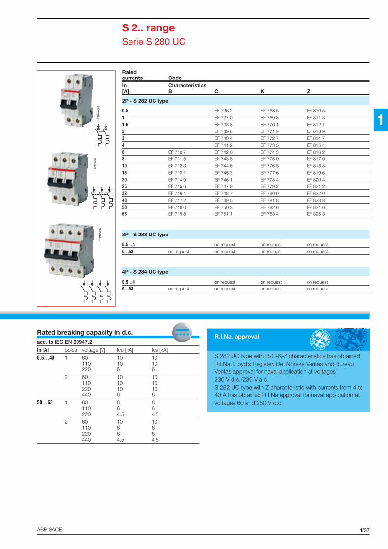
In [A] poles voltage [V] Icu [kA] Ics [kA]
0.5...40 1 60 10 10110 10 10220 6 6
2 60 10 10110 10 10220 10 10440 6 6
50...63 1 60 6 6110 6 6220 4.5 4.5
2 60 10 10110 6 6220 6 6440 4.5 4.5
Ratedcurrents CodeIn Characteristics[A] B C K Z
2P - S 282 UC type
0.5 EF 736 2 EF 768 5 EF 810 5
1 EF 737 0 EF 769 3 EF 811 3
1.6 EF 738 8 EF 770 1 EF 812 1
2 EF 739 6 EF 771 9 EF 813 9
3 EF 740 4 EF 772 7 EF 814 7
4 EF 741 2 EF 773 5 EF 815 4
6 EF 710 7 EF 742 0 EF 774 3 EF 816 2
8 EF 711 5 EF 743 8 EF 775 0 EF 817 0
10 EF 712 3 EF 744 6 EF 776 8 EF 818 8
16 EF 713 1 EF 745 3 EF 777 6 EF 819 6
20 EF 714 9 EF 746 1 EF 778 4 EF 820 4
25 EF 715 6 EF 747 9 EF 779 2 EF 821 2
32 EF 716 4 EF 748 7 EF 780 0 EF 822 0
40 EF 717 2 EF 749 5 EF 781 8 EF 823 8
50 EF 718 0 EF 750 3 EF 782 6 EF 824 6
63 EF 719 8 EF 751 1 EF 783 4 EF 825 3
3P - S 283 UC type
0.5...4 on request on request on request
6...63 on request on request on request on request
4P - S 284 UC type
0.5...4 on request on request on request
6...63 on request on request on request on request
S 2.. rangeSerie S 280 UC
TEP
M00
56TE
PM
0057
TEP
M00
58
R.I.Na. approval
S 282 UC type with B-C-K-Z characteristics has obtainedR.I.Na, Lloyd’s Register, Det Norske Veritas and BureauVeritas approval for naval application at voltages230 V d.c./230 V a.c.S 282 UC type with Z characteristic with currents from 4 to40 A has obtained R.I.Na approval for naval application atvoltages 60 and 250 V d.c.

1/38 ABB SACE
1
S 2.. rangeM 280 magnetic only series
Rated currents CodeIn I magn[A] [A]
1P - M 281 type
0.5 7 KU 470 7
1 14 KU 471 5
1.6 23 KU 472 3
2.5 32 KU 473 1
4 56 KU 474 9
6.3 88 KU 475 6
10 140 KU 476 4
12.5 175 KU 477 2
16 192 KU 478 0
20 240 KU 479 8
25 300 KU 480 6
32 384 KU 481 4
40 480 KU 482 2
50 600 KU 483 0
63 700 KU 484 8
2P - M 282 type
0.5 7 KU 602 5
1 14 KU 603 3
1.6 23 KU 604 1
2.5 32 KU 605 8
4 56 KU 606 6
6.3 88 KU 607 4
10 140 KU 608 2
12.5 175 KU 609 0
16 192 KU 610 8
20 240 KU 611 6
25 300 KU 612 4
32 384 KU 613 2
40 480 KU 614 0
50 600 KU 615 7
63 700 KU 616 5
TEP
M00
62
Protection against short-circuit overcurrents in the supplycircuits of motors. For protection against overloadcurrents, additional thermal protection is necessary.
Application
Connections for UNIFIX available
RCD blocks
DDA 63 A

1/39ABB SACE
1
Rated currents CodeIn I magn[A] [A]
3P - M 283 type
0.5 7 KU 617 3
1 14 KU 618 1
1.6 23 KU 619 9
2.5 32 KU 620 7
4 56 KU 621 5
6.3 88 KU 622 3
10 140 KU 623 1
12.5 175 KU 624 9
16 192 KU 625 6
20 240 KU 626 4
25 300 KU 627 2
32 384 KU 628 0
40 480 KU 629 8
50 600 KU 630 6
63 700 KU 631 4
4P - M 284 type
0.5 7 KU 632 2
1 14 KU 633 0
1.6 23 KU 634 8
2.5 32 KU 635 5
4 56 KU 636 3
6.3 88 KU 637 1
10 140 KU 638 9
12.5 175 KU 639 7
16 192 KU 640 5
20 240 KU 641 3
25 300 KU 642 1
32 384 KU 643 9
40 480 KU 644 7
50 600 KU 645 4
63 700 KU 646 2
S 2.. rangeM 280 magnetic only series
Rated breaking capacity in a.c.acc. to IEC EN 60947.2
In [A] poles [V] Icu [kA] Ics [%]
0.5...1.6 - 10…25 3, 4 230 40 75
2.5...6.3 - 50…63 3, 4 230 25 75
32…40 3, 4 230 30 75
0.5...1.6 - 10…25 3, 4 400 25 50
2.5...6.3 - 50…63 3, 4 400 15 50
32…40 3, 4 400 20 50
TEP
M00
63

1/40 ABB SACE
1
S2-H..AUXILIARYCONTACT
S2-S/HAUXILIARY
CONTACT +SIGNAL
CONTACT
S2-A1I, S2-A2ISHUNT TRIP
S2-H..AUXILIARYCONTACT
S2-BPMECHANICAL
INTERLOCK
S2-BPSMECHANICAL
INTERLOCKWITH SIGNAL
CONTACT
S2-A1I, S2-A2ISHUNT TRIP
S2-BP, S2-BPSMECHANICALINTERLOCK
S2-BM.INDERVOLTAGERELEASE
S2-S/HAUXILIARY
CONTACT +SIGNAL
CONTACT
S2-SSIGNAL
CONTACT
S2-BM..UN DERVOLTAGE
RELEASE
S2-SSIGNAL
CONTACT
S 240-S 250-S 270-S 280MCB
DDARCDBLOCK2P, 3P, 4PS2-S
SIGNALCONTACT
S2-CMMOTOROPERATINGDEVICES2P, 3P, 4P
Examples of combinations of S 240, S 250, S 270 and S 280 series circuit-breakers with auxiliary elements (maximum configurations)
S 2.. rangeAuxiliary elements
The S 2.. range circuit-breakersare supported by a wholegroup of auxiliary elements withmany functions and configura-tions.
Shunt trips, undervoltage re-leases, auxiliary contacts, sig-nal contacts, mechanical inter-locks and motor operating de-vices are available.
Each auxiliary element hasbeen studied so that it can beinstalled on the highest possi-ble number of circuit-breakersthus simplifying selection for thesector operators.
A wide range of auxiliary ele-ments considerably improvesthe performance of the circuit-breakers and enables innova-tive and integrated solutions tobe used in every installation.
TEP
M04
25
1/41ABB SACE
1
S 2.. rangeAuxiliary elements
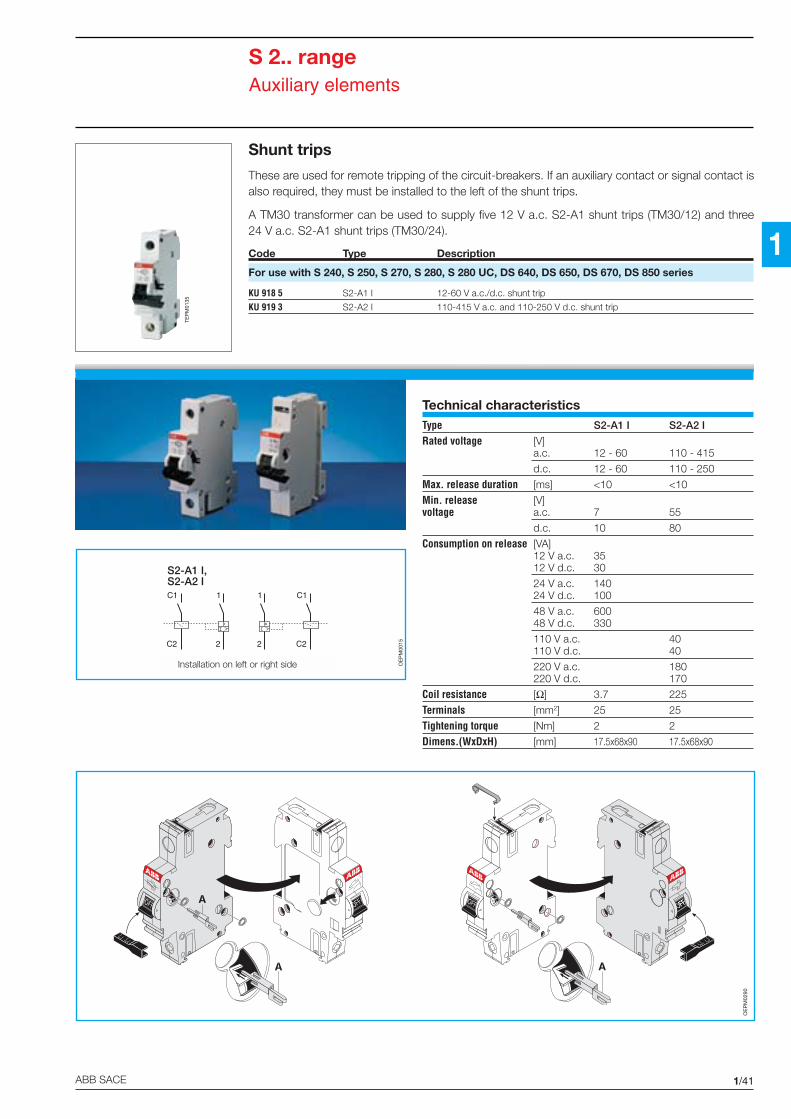
Shunt trips
These are used for remote tripping of the circuit-breakers. If an auxiliary contact or signal contact isalso required, they must be installed to the left of the shunt trips.
A TM30 transformer can be used to supply five 12 V a.c. S2-A1 shunt trips (TM30/12) and three24 V a.c. S2-A1 shunt trips (TM30/24).
Code Type Description
For use with S 240, S 250, S 270, S 280, S 280 UC, DS 640, DS 650, DS 670, DS 850 series
KU 918 5 S2-A1 I 12-60 V a.c./d.c. shunt trip
KU 919 3 S2-A2 I 110-415 V a.c. and 110-250 V d.c. shunt trip
Technical characteristicsType S2-A1 I S2-A2 I
Rated voltage [V]a.c. 12 - 60 110 - 415
d.c. 12 - 60 110 - 250
Max. release duration [ms] <10 <10
Min. release [V]voltage a.c. 7 55
d.c. 10 80
Consumption on release [VA]12 V a.c. 3512 V d.c. 30
24 V a.c. 14024 V d.c. 100
48 V a.c. 60048 V d.c. 330
110 V a.c. 40110 V d.c. 40
220 V a.c. 180220 V d.c. 170
Coil resistance [Ω] 3.7 225
Terminals [mm2] 25 25
Tightening torque [Nm] 2 2
Dimens.(WxDxH) [mm] 17.5x68x90 17.5x68x90
1
2
C1
C2
1
2
C1
C2
S2-A1 I,S2-A2 I
OE
PM
0015
TEP
M01
35
C1
C2
C1
C2
OE
PM
0290
Installation on left or right side

1/42 ABB SACE
1
S 2.. rangeAuxiliary elements
Auxiliary/signal contacts
The auxiliary contact indicates the position of the circuit-breaker contacts. When the position of thecontacts changes, whether manually or automatically, it indicates their status.The signal contact indicates the position of the circuit-breaker after automatic release of the circuit-breaker caused by overload or short-circuit. For manual operation, it does not trip.
LegendS2-H = auxiliary contactS2-S = signal contactS2-SH = auxiliary + signal contact
= signal contact (1 change over contact)= auxiliary + signal contact (2 change over contacts)
Technical characteristicsType S2-H11 I S2-H20 I S2-H02 I S2-H21 S2-H12 S2-H30 S2-H03
S2-H11 X S2-H20 X S2-H02 XDescription 1NO+1NC 2NO 2NC 2NO+1NC 1NO+2NC 3NO 3NCAlternating Ue [V]••••••••••••••••••••••••••••••• 240 415current Ie [A]••••••••••••••••••••••••••••••• 6 2Direct Ue [V]•••••••••••••••••••••••• 24 60 110 250current Ie [A]•••••••••••••••••••••••• 4 2 1.5 1Min.operatingvoltage [V] 12 a.c.-12 d.c.Min. operatingcurrent [mA] 12Terminals [mm2] up to 2x1.5Dielectric strength [kV] 3Resistance to short-circuitat 240 V a.c. [A] 1000 (protected with S 2 breaker characteristic K - 6 A)Impulse voltage withstandcapacity [kV] 4Tightening torque [Nm] 0.7Dimensions (WxDxH) [mm] 8.75x68x90
NB: the auxiliary contacts S2-H11 X, S2-H20 X, S2-H02 X differ from the contacts S2-H11, S2-H20, S2-H02 in that they do not have a terminal to tighten the cablewhich is replaced by a bayonet for the Faston connection.
OE
PM
0018
11 21 31
12 22 32
1
2
13 23 33
14 24 34
1
2
11 21 33
12 22 34
1
2
11 23 33
12 24 34
1
2
11 21
12 22
1
2
13 23
14 24
1
2
13 21
14 22
1
2

1/43ABB SACE
1TE
PM
0140
TEP
M01
38
S2-S S2-SH
240 4156 2
250 110 60 240.5 1 1 4
12 a.c.-12 d.c.
12up to 2x1.5
3
1000 (protected with S 2 breaker characteristic K - 6 A)
40.7
8.75x68x90
Code Type Description
For use with S 240, S 250, S 270, S 280, S 280 UC, DS 640, DS 650, DS 670, DS 850 series
KU 925 0 S2-H11 I auxiliary contact 1NO+1NC (1/2 module)
KU 926 8 S2-H02 I auxiliary contact 2NC (1/2 module)
KU 927 6 S2-H 20 I auxiliary contact 2NO (1/2 module)
KU 897 1 S2-H11X auxiliary contact 1NO+ 1NC (1/2 module) with Faston connections
KU 899 7 S2-H20X auxiliary contact 2NO (1/2 module) with Faston connections
KU 898 9 S2-H02X auxiliary contact 2NC (1/2 module) with Faston connections
KU 891 4 S2-H21 auxiliary contact 2NO+1NC (1/2 module)
KU 890 6 S2-H12 auxiliary contact 1NO+2NC (1/2 module)
KU 893 0 S2-H30 auxiliary contact 3NO (1/2 module)
KU 892 2 S2-H03 auxiliary contact 3NC (1/2 module)
KU 903 7 S2-S signal contact (1/2 module)
KU 902 9 S2-S/H signal contact + auxiliary contacts (1/2 module)TEP
M01
39
95
96 98
1
2
95
96 98
1
2
95
96 98
1
2
Aperturaautomatica
Aperturamanuale
S 2.. rangeAuxiliary elements
11
12 14
1
2
95
96 98
11
12 14
1
2
95
96 98
11
12 14
1
2
95
96 98
Aperturaautomatica
Aperturamanuale
Automaticopening
Manualopening
Automaticopening
Manualopening
1/44 ABB SACE
1
S 2.. rangeAuxiliary elements
1
2
D1
D2 OE
PM
0020
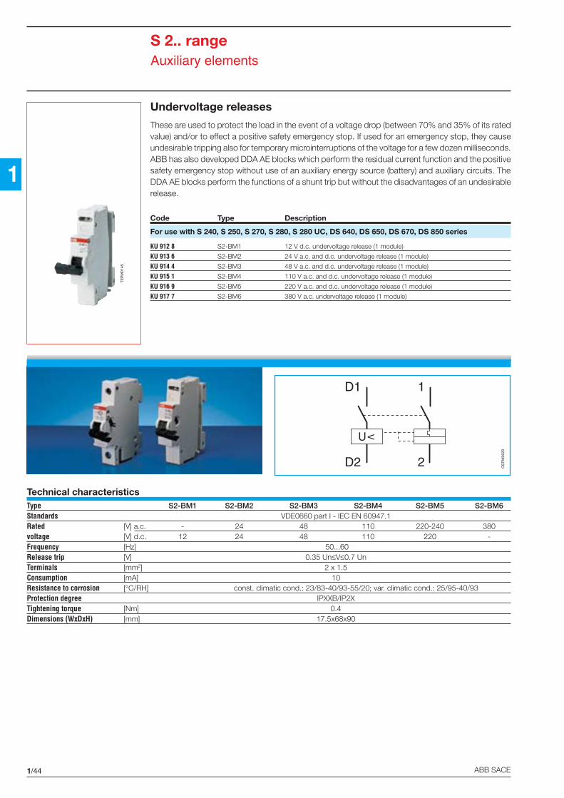
Undervoltage releases
These are used to protect the load in the event of a voltage drop (between 70% and 35% of its ratedvalue) and/or to effect a positive safety emergency stop. If used for an emergency stop, they causeundesirable tripping also for temporary microinterruptions of the voltage for a few dozen milliseconds.ABB has also developed DDA AE blocks which perform the residual current function and the positivesafety emergency stop without use of an auxiliary energy source (battery) and auxiliary circuits. TheDDA AE blocks perform the functions of a shunt trip but without the disadvantages of an undesirablerelease.
Code Type Description
For use with S 240, S 250, S 270, S 280, S 280 UC, DS 640, DS 650, DS 670, DS 850 series
KU 912 8 S2-BM1 12 V d.c. undervoltage release (1 module)
KU 913 6 S2-BM2 24 V a.c. and d.c. undervoltage release (1 module)
KU 914 4 S2-BM3 48 V a.c. and d.c. undervoltage release (1 module)
KU 915 1 S2-BM4 110 V a.c. and d.c. undervoltage release (1 module)
KU 916 9 S2-BM5 220 V a.c. and d.c. undervoltage release (1 module)
KU 917 7 S2-BM6 380 V a.c. undervoltage release (1 module)
Technical characteristicsType S2-BM1 S2-BM2 S2-BM3 S2-BM4 S2-BM5 S2-BM6Standards VDE0660 part I - IEC EN 60947.1Rated [V] a.c. - 24 48 110 220-240 380voltage [V] d.c. 12 24 48 110 220 -Frequency [Hz] 50...60Release trip [V] 0.35 Un≤V≤0.7 UnTerminals [mm2] 2 x 1.5Consumption [mA] 10Resistance to corrosion [°C/RH] const. climatic cond.: 23/83-40/93-55/20; var. climatic cond.: 25/95-40/93Protection degree IPXXB/IP2XTightening torque [Nm] 0.4Dimensions (WxDxH) [mm] 17.5x68x90
TEP
M01
45

1/45ABB SACE
1
S 2.. rangeAuxiliary elements
Mechanical interlocks
Auxiliary element for MCBs and RCBOs. It automatically releases the relative circuit-breaker whenthe panel of the electric switchboard is opened or removed. The release is only mechanical and actson the release elements of the circuit-breakers.
Code Type Description
For use with S 240, S 250, S 270, S 280, S 280 UC, DS 640, DS 650, DS 670, DS 850 series
EF 998 8 S2-BP mechanical interlock
TEP
M01
46
Technical characteristics of mechanical interlockDimensions (WxDxH) [mm] 17.5x68x90
1
2
BP
OE
PM
0021
Mechanical interlocks with signal contact
It automatically releases the relative circuit-breaker when the panel or the door of the electricswitchboard is opened or removed and indicates that this has occurred by way of a contact.
Code Type Description
For use with S 240, S 250, S 270, S 280, S 280 UC, DS 640, DS 650, DS 670, DS 850 series
EF 999 6 S2-BPS mechanical interlock with signal contact
Technical characteristics of mechanical interlockwith signal contact
Max. contact capacity at 250 V a.c. 8A ohmic[In] 2A inductive
Max. contact capacity at 24 V d.c. 4A ohmic[In] 2A inductive
Mechanical endurance 4000
Operatingtemperature [°C] -25...+80
Contact material silver alloy, gold-plated
Insulation voltage terminal/terminal:[V] 1000
terminal/earth:[V] 1500
1
2
BP
Mechanical interlocks
Mechanical interlocks withsignal contact
TEP
M01
426
1/46 ABB SACE
1
S 2.. rangeAuxiliary elements
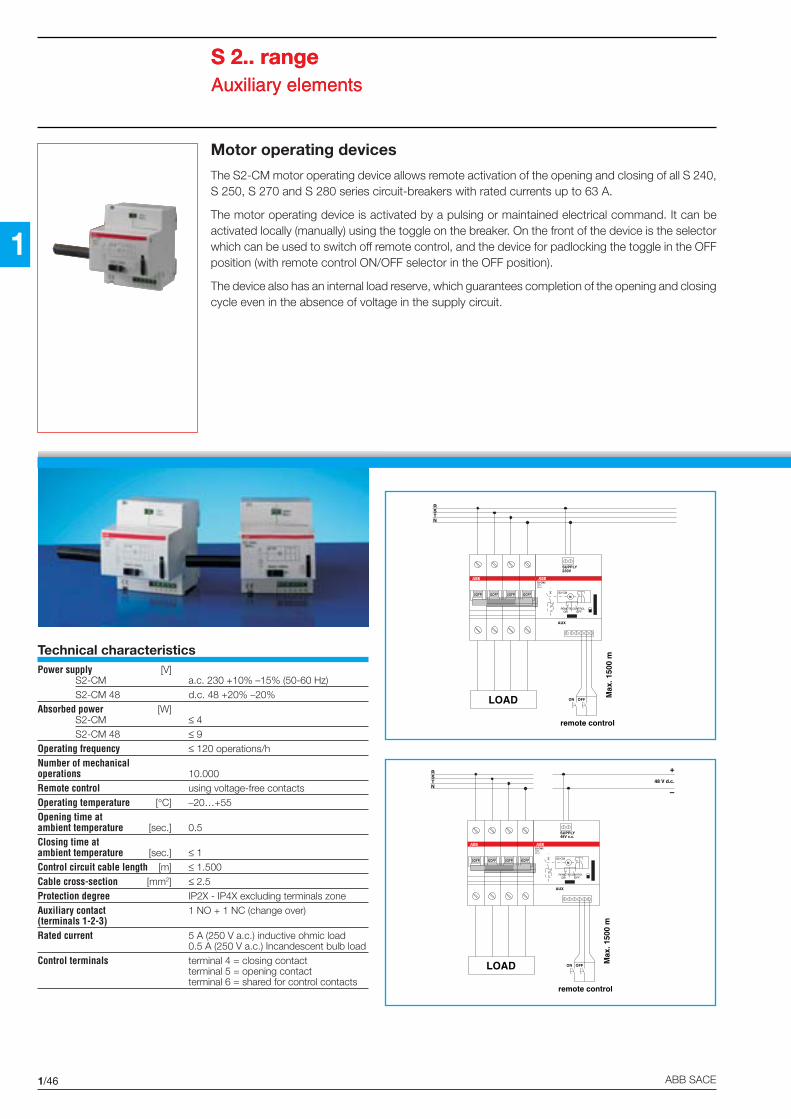
Motor operating devices
The S2-CM motor operating device allows remote activation of the opening and closing of all S 240,S 250, S 270 and S 280 series circuit-breakers with rated currents up to 63 A.
The motor operating device is activated by a pulsing or maintained electrical command. It can beactivated locally (manually) using the toggle on the breaker. On the front of the device is the selectorwhich can be used to switch off remote control, and the device for padlocking the toggle in the OFFposition (with remote control ON/OFF selector in the OFF position).
The device also has an internal load reserve, which guarantees completion of the opening and closingcycle even in the absence of voltage in the supply circuit.
Technical characteristicsPower supply [V]
S2-CM a.c. 230 +10% –15% (50-60 Hz)S2-CM 48 d.c. 48 +20% –20%
Absorbed power [W]S2-CM ≤ 4S2-CM 48 ≤ 9
Operating frequency ≤ 120 operations/hNumber of mechanicaloperations 10.000Remote control using voltage-free contactsOperating temperature [°C] –20…+55Opening time atambient temperature [sec.] 0.5Closing time atambient temperature [sec.] ≤ 1Control circuit cable length [m] ≤ 1.500Cable cross-section [mm2] ≤ 2.5Protection degree IP2X - IP4X excluding terminals zoneAuxiliary contact 1 NO + 1 NC (change over)(terminals 1-2-3)Rated current 5 A (250 V a.c.) inductive ohmic load
0.5 A (250 V a.c.) Incandescent bulb loadControl terminals terminal 4 = closing contact
terminal 5 = opening contactterminal 6 = shared for control contacts
S 2.. rangeAuxiliary elements
ON
RSTN
SUPPLY230V
OFF
Max
. 150
0 m
AUX
LOAD
remote control
0OFF 0OFF 0OFF 0OFF
S2-CM2230V ~50 Hz
S2-CM
REMOTE CONTROLON OFF
M
ON
RSTN
SUPPLY48V c.c.
OFF
Max
. 150
0 m
AUX
LOAD
remote control
48 V d.c.
+
–
0OFF 0OFF 0OFF 0OFF
S2-CM2230V ~50 Hz
S2-CM
REMOTE CONTROLON OFF
M

1/47ABB SACE
1
0 OFF 0 OFF 0 OFF 0 OFF
0 OFF 0 OFF 0 OFF 0 OFF
21
0 OFF 0 OFF 0 OFF 0 OFF
0 OFF 0 OFF 0 OFF 0 OFF
ON
OFF
0 OFF 0 OFF 0 OFF 0 OFF
0 OFF 0 OFF 0 OFF 0 OFF
3 4
Code Type Description
230 V a.c. motor operating device
KU 936 7 S2-CM2 for two-pole circuit-breaker
KU 937 5 S2-CM3 for three-pole circuit-breaker
KU 938 3 S2-CM4 for four-pole circuit-breaker
48 V d.c. motor operating device
on request S2-CM2 48 V d.c. for two-pole circuit-breaker
on request S2-CM3 48 V d.c. for three-pole circuit-breaker
on request S2-CM4 48 V d.c. for four-pole circuit-breaker
S 2.. rangeAuxiliary elements

1/48 ABB SACE
1
S 2.. rangeAccessories
The S 2.. range has a variedand comprehensive group ofaccessories which can quicklyand easily resolve even thesmallest of installation problemsand effect functional and safeinstallations in the best possi-ble way.
Terminal cover: enables wallmounting of MCBs and RCDs(wall-mounting consumer unitswith 2/4/6/8 module capacityfor installation of single circuit-breakers).
Spacer - false pole: com-pletes a line of modular circuit-breakers in switchboards andconsumer units, with projectingelements with the same profileas the S 2.. range circuit-break-ers (making the front of the cir-cuit-breakers uniform).
Mechanical lock: blocks thecircuit-breaker knob.
END clamp: laterally blocks thecircuit-breakers on the DIN rail.
Flange for rear board mount-ing: mounts the circuit-breakeron the door or front panel ofswitchboards.
One-pole withdrawable kit:makes the circuit-breaker ex-tractable. It is installed horizon-tally or vertically onto the DINrail.
Screw protection cover: insu-lates and seals the terminalscrews so that they are inac-cessible and raises the protec-tion degree to IP40.
Block for rotary operation:transforms operating of the cir-cuit-breaker knob into rotaryoperation.
Motor operating device: acti-vates the opening/closing com-mand of S 2.. two-pole, three-pole and four-pole MCBs.
Connection busbars: enableparallel power supply of severalcircuit-breakers with the samenumber of poles.
TEP
M01
427
1

1/49ABB SACE
1
S 2.. rangeAccessories
Code Type Description
For use with S 240, S 250, S 270, S 280, DS 640, DS 650, DS 670, DS 850 series
EB 176 5 FP1 spacer - false pole - 1 module
EB 177 3 FP2 spacer - false pole - 2 modules
EB 178 1 FP4 spacer - false pole - 4 modules
EB 179 9 FP6 spacer - false pole - 6 modules
EB 183 1 SFP support for FP spacer - false poleThe SFP support is necessary for spacer-false pole installation on DIN rail
EA 214 5 BSA1 mechanical block
EA 213 7 BSA2 padlock for BSA1
EA 215 2 END CLAMP clamp for DIN rail
KU 930 0 ME1 flange for rear board fixing 1 module - IP40
KU 931 8 ME2 flange for rear board fixing 2 modules - IP40
KU 932 6 ME3 flange for rear board fixing 3 modules - IP40
KU 933 4 ME4 flange for rear board fixing 4 modules - IP40
KU 934 2 ME6 flange for rear board fixing 6 modules - IP40
KU 935 9 ME8 flange for rear board fixing 8 modules - IP40
KU 939 1 S2-MP2 rear terminal for rear board fixing 25mm2 for S 2
Mechanical block BSA1
Padlock BSA2
Flange for rear board fixing ME4
FP2 spacer – false pole +SFP support
Support for SFP spacer - falsepole
Terminal S2-MP2

1/50 ABB SACE
1
S 2.. rangeAccessories
Code Type DescriptionKU 943 3 CPV2 sealable screw protection cover for S 2.. circuit-breakers
KU 922 7 S2-EST withdrawable kit for S 2.. circuit-breakers up to 32 A
EP 742 9 ST label carrier
EP 743 7 ST-E neutral labels
KU 894 8 S2-DH block for rotary operation for S 2.. circuit-breakers
EO 010 2 OHB 2AJ OHB 2AJ handle for rotary operation block, black, padlockable IP65
EO 011 0 OHY 2AJ handle for rotary operation block, red/yellow, padlock possible, IP65
EO 071 4 OXS 5X 85 shaft for rotary operation 85 mm long
EO 066 4 OXS 5X 10⁵ shaft for rotary operation 105 mm long
EO 067 2 OXS 5X 120 shaft for rotary operation 120 mm long
EO 068 0 OXS 5X 130 shaft for rotary operation 130 mm long
EO 109 2 OXS 5X 160 shaft for rotary operation 160 mm long
EO 069 8 OXS 5X 180 shaft for rotary operation 180 mm long
EO 110 0 OXS 5X 250 shaft for rotary operation 250 mm long
EO 070 6 OXS 5X 330 shaft for rotary operation block 330 mm long
ST label carrier
CPV2
S2-EST
S2-DH
OHY 2AJ
OSX 5X

1/51ABB SACE
1
S 2.. rangeAccessories
Code Type Description
Insulated busbars (1 m long- max. 56 poles) - fork type
EA 643 5 BCF 1/100 for one-pole circuit-breaker
EA 644 3 BCF 1H/100 for one-pole circuit-breaker with auxiliary contact
EA 645 0 BCF 2/100 for two-pole circuit-breaker
EA 646 8 BCF 3/100 for three-pole circuit-breaker
EA 647 6 BCF 4/100 for four-pole circuit-breaker
EA 648 4 EK-C-2+3 lateral end cover for busbars BCF 2/100 and BCF 3/100
EA 649 2 EK-C-4 lateral end cover for busbars BCF 4/100
Insulated busbars (1 m long - max. 56 poles) - pin type
EA 650 0 BCP 1/100 for one-pole circuit-breaker
EA 524 7 BCP 2/N for two-pole circuit-breaker
EA 525 4 BCP 3/N for three-pole circuit-breaker
EA 526 2 BCP 4/N for four-pole circuit-breaker
EA 549 4 EK-SBS 2 lateral end cover for busbars BCP 2/N
EA 550 2 EK-SBS 4 lateral end cover for busbars BCP 3/N-4/N
EA 546 0 MR/35 S terminal for supply cable for busbars BCF/N and BCP/N
Depth adapters
EA 450 5 S2-AD160 adapter for aligning S2 range circuit-breakers withS 500 range circuit-breakers
BCF 4/100
BCF 1/100
BCP 4/N
MR/35 S

1/52 ABB SACE
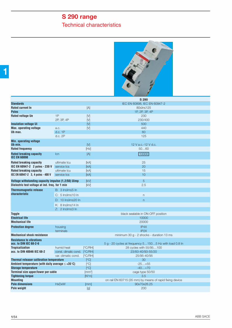
1The S 290 range of circuit-breakers enables the use inswitchboards and consumerunits for modular devices with45 mm slotting and rated cur-rents up to 125 A.
They can be mounted along-side standard modular circuit-breakers because of theirmodular design and ability to beinstalled on 35 mm DIN EN50022 rails.
The S 290 range circuit-brea-kers are available in 1-2-3-4pole versions with a width equalto 1 1/2 modules per pole(27 mm).
The time-current characteris-tics available are C and D, asnormally required for circuit-breakers which are used formain switchboard functions orare however installed upstreamof other MCBs.
The fact that these devices fullycomply with the IEC 898/EN60898 Standards means thatthey can be used by untrainedstaff, as sometimes required forcircuit-breakers with theserated currents.
The S 290 circuit-breakers havea series of special auxiliary ele-ments which effect the normalfunctions required in moderninstallations (indication of trip-ping, remote release, etc).
TEP
M01
430
TEP
M01
429
TEP
M01
428

1/53ABB SACE
1
Contents
Technical characteristics .......................................................................................................1/54
Order information
S 291, S 292, S 293, S 294 series ........................................................................................ 1/55
Auxiliary elements
Shunt trips ............................................................................................................................. 1/57
Auxiliary/signal contacts ........................................................................................................1/58
Undervoltage releases ..........................................................................................................1/59
S 290 range
1/54 ABB SACE
1
S 290 rangeTechnical characteristics
S 290Standards IEC EN 60898, IEC EN 60947-2Rated current In [A] 80≤In≤125Poles 1P, 2P, 3P, 4PRated voltage Ue 1P [V] 230
2P, 3P, 4P [V] 230/400Insulation voltage Ui [V] 500Max. operating voltage a.c. [V] 440Ub max. d.c. 1P 60
d.c. 2P 125
Min. operating voltageUb min. [V] 12 V a.c.-12 V d.c.Rated frequency [Hz] 50…60
Rated breaking capacity Icn [A] 10000IEC EN 60898
Rated breaking capacity ultimate Icu [kA] 25IEC EN 60947-2 2 poles - 230 V service Ics [kA] 20Rated breaking capacity ultimate Icu [kA] 15IEC EN 60947-2 3, 4 poles - 400 V service Ics [kA] 10
Voltage withstanding capacity impulse (1,2/50) Uimp [kV] 5Dielectric test voltage at ind. freq. for 1 min [kV] 2.5
Thermomagnetic release B: 3 In≤Im≤5 Incharacteristic C: 5 In≤Im≤10 In n
D: 10 In≤Im≤20 In n
K: 8 In≤Im≤14 InZ: 2 In≤Im≤3 In
Toggle black sealable in ON-OFF positionElectrical life 10000Mechanical life 20000
Protection degree housing IP4Xterminals IP2X
Mechanical shock resistance minimum 30 g - 2 shocks - duration 13 ms
Resistance to vibrationsacc. to DIN IEC 68-2-6 5 g - 20 cycles at frequency 5…150…5 Hz with load 0.8 InTropicalization humid heat [°C/RH] 28 cycles with 55/95…100acc. to DIN 40046 IEC 68-2 const. climatic cond. [°C/RH] 23/83-40/93-55/20
var. climatic cond. [°C/RH] 25/95-40/95Thermal releaser calibration temperature [°C] 30Ambient temperature (with daily average ≤ +35°C) [°C] -25…+55Storage temperature [°C] -40…+70Terminal size upper/lower per cable [mm2] cage type 50/50Tightening torque [N*m] 3.5Mounting on rail EN 60715 (35 mm) by means of rapid fixing devicePole dimensions HxDxW [mm] 90x70x26.25Pole weight [g] 200

1/55ABB SACE
1
Breaking capacity in a.c.acc. to IEC EN 60898
In [A] poles voltage [V] Icn [kA]
80...125 All 230/400 10
acc. to IEC EN 60947.2
In [A] poles voltage [V] Icn [kA] Ics [kA]
80...125 1 230 15 10
2 127 50 25230 25 20400 15 10
3, 4 230 25 20400 15 10
Breaking capacity in d.c.acc. to IEC EN 60947.2
In [A] poles voltage [V] Icn [kA] Ics [kA]
80...125 1 60 15 15
2 110 15 15
S 290 rangeS 291, S 292, S 293, S 294 series
C (Im=5…10 In); D (Im=10…20 In)
Tripping characteristics
Application: industrial
RCD blocks
DDA 100 A only on C curve circuit-breakers
Rated currents CodeIn Characteristic[A] C D
1P - S 291 type
80 KU 950 8 KU 974 8
100 KU 951 6 KU 975 5
125 KU 952 4
2P - S 292 type
80 KU 953 2 KU 977 1
100 KU 954 0 KU 978 9
125 KU 955 7
3P - S 293 type
80 KU 956 5 KU 980 5
100 KU 957 3 KU 981 3
125 KU 958 1
4P - S 294 type
80 KU 959 9 KU 983 9
100 KU 960 7 KU 984 7
125 KU 961 5
Note: the 100A DDA RCD blocks are suitable for assembly with the S 290 seriesMCBs with C characteristic and In≤100 A
TEP
M00
70
TEP
M00
59
TEP
M00
71
TEP
M00
72

1/56 ABB SACE
1
S 290 rangeAuxiliary elements
The S 290 circuit-breakers aresupplied with special shunttrips, undervoltage releasesand contacts (auxiliary and sig-nal).
All the accessories are installedto the right of the circuit-breaker. The left part is used forinstalling RCD blocks.
The procedures for accesso-rizing are shown in the figure.
TEP
M01
431
S 290 ASHUNTTRIP
S290 UAUNDERVOLTAGERELEASE
S2902P, 3P, 4P
MCB
S 290 H11AUXILIARYCONTACT
S 290 H11AUXILIARYCONTACT
S 290 SSIGNALCONTACT
S 290 ASHUNTTRIP
S 290 UAUNDERVOLTAGERELEASE
DDARCD BLOCK
S 290 SSIGNALCONTACT
S 290 H11AUXILIARYCONTACT
S 290 SSIGNALCONTACT
S 290 H11AUXILIARYCONTACT
S 290 SSIGNALCONTACT
Examples of combinations of S 290 series circuit-breakers with auxiliary elements (maximum configurations)

1/57ABB SACE
1
Technical characteristicsType S 290 A1 S 290 A2
Rated voltage [V]a.c. 110...415 24...48
d.c. 110...250 24...48
Max. release duration [ms] <10 <10
Consumption on release [VA]a.c. 20÷180 40÷200
d.c. 20÷180 40÷200
Terminals [mm2] 25 25
Tightening torque [Nm] 2 2
Dimensions (WxDxH) [mm] 17.5x68x90 17.5x68x90
S 290 rangeAuxiliary elements
Shunt trips
These are used for remote tripping of the circuit-breakers.
Code Type Description
For S 290 series
KU 989 6 S290 A1 110-415 V a.c. and 110 V d.c. shunt trip
KU 991 2 S290 A2 24-48 V a.c./d.c. shunt trip
TEP
M01
37TE
PM
0136
1
2
C1
C2
S 290 A1S 290 A2
Installation only on right
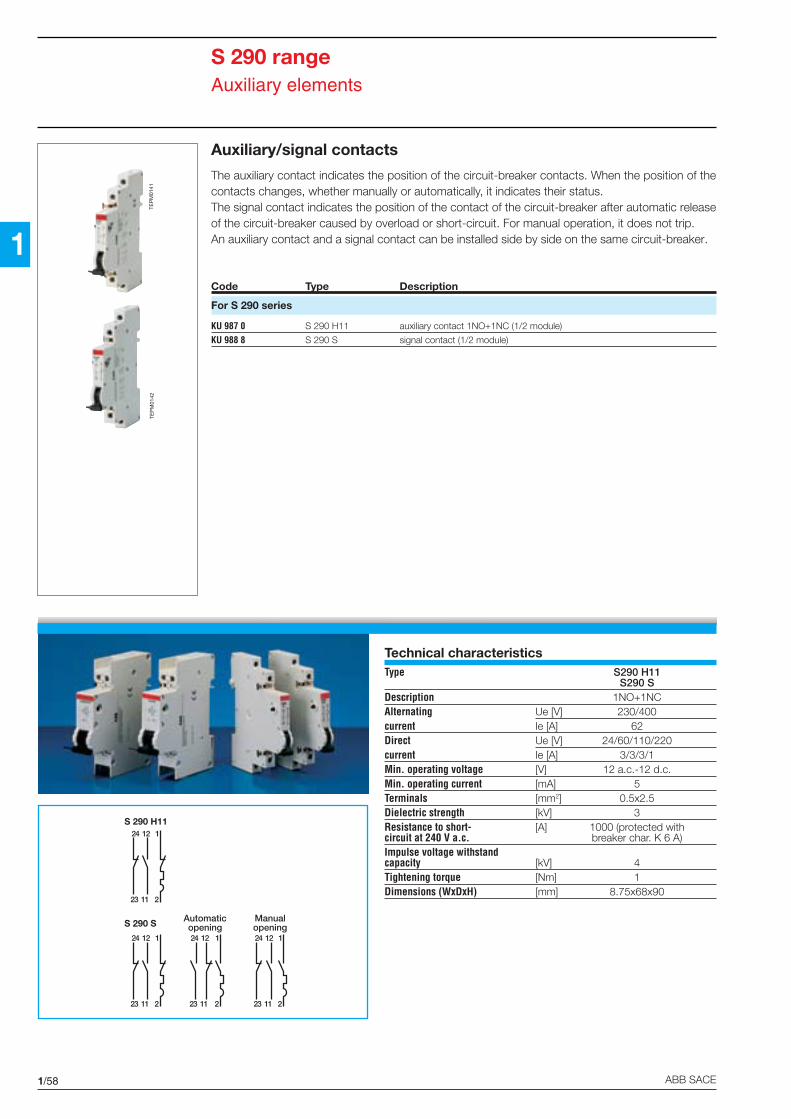
1/58 ABB SACE
1
S 290 rangeAuxiliary elements
Auxiliary/signal contacts
The auxiliary contact indicates the position of the circuit-breaker contacts. When the position of thecontacts changes, whether manually or automatically, it indicates their status.The signal contact indicates the position of the contact of the circuit-breaker after automatic releaseof the circuit-breaker caused by overload or short-circuit. For manual operation, it does not trip.An auxiliary contact and a signal contact can be installed side by side on the same circuit-breaker.
Code Type Description
For S 290 series
KU 987 0 S 290 H11 auxiliary contact 1NO+1NC (1/2 module)
KU 988 8 S 290 S signal contact (1/2 module)
Technical characteristicsType S290 H11
S290 SDescription 1NO+1NCAlternating Ue [V] 230/400current Ie [A] 62Direct Ue [V] 24/60/110/220current Ie [A] 3/3/3/1Min. operating voltage [V] 12 a.c.-12 d.c.Min. operating current [mA] 5Terminals [mm2] 0.5x2.5Dielectric strength [kV] 3Resistance to short- [A] 1000 (protected withcircuit at 240 V a.c. breaker char. K 6 A)Impulse voltage withstandcapacity [kV] 4Tightening torque [Nm] 1Dimensions (WxDxH) [mm] 8.75x68x90
TEP
M01
42TE
PM
0141
Automaticopening
Manualopening
24 12
23 11
1
2
24 12
23 11
1
2
24 12
23 11
1
2
24 12
23 11
1
2
S 290 S
S 290 H11

1/59ABB SACE
1
S 290 rangeAuxiliary elements
Undervoltage releases
These are used to protect the load in the event of a voltage drop (between 70% and 35% of its ratedvalue) and/or to effect an emergency stop in positive safety.
Code Type Description
For S 290 series
KU 990 4 S 290 UA 230 230 V a.c. undervoltage release (1 module)
Technical characteristicsType S 290-UA 230Standards VDE0660 part I - IEC EN 60947.1Rated [V] a.c. 230voltage [V] d.c. -Frequency [Hz] 50...60Release trip threshold [V] 0.35 Un≤V≤0.7 UnTerminals [mm2] 2x1.5Consumption [mA] 10Resistance to corrosion [°C/RH] constant atmosphere:
23/83-40/93-55/20;variable atmosphere:
25/95-40/93Protection degree IPXXB/IP2XTightening torque [Nm] 0.4Dimensions (WxDxH) [mm] 17.5x68x90
1
2
D1
D2
OE
PM
0020
TEP
M01
432

1/60 ABB SACE
1The S 500 circuit-breakers havea high breaking capacity whichis obtained using the “doubleinterruption” technique.
These circuit-breakers have aspecial movable fork contactwhich operates with two sepa-rate breaking chambers foreach pole in the device.
This structure leads to a highenergy limitation capacity and,consequently, a high breakingcapacity.
Because of the tripping speed(less than 3 ms up to 50 kA),the S 500 breakers offer con-siderable protection to thestandard modular circuit-breakers installed downstream.
If they are installed downstreamof moulded-case circuit-brea-kers, on the other hand, theyeasily carry out selective coor-dination with the upstream pro-tection devices.
The S 500 circuit-breakers areavailable in 1-2-3-4 pole ver-sions with width equal to 1 1/2modules per pole (27 mm), upto a rated current of 63 A.
The time-current characteristicsavailable are C and B for pro-tecting circuits in alternatingcurrent and B for protecting cir-cuits in direct current (S 500 UCseries).
S 500-K versions with adjus-table thermal and S 500-KMversions with magnetic onlyreleasers are also available.
TEP
M01
434
TEP
M01
433
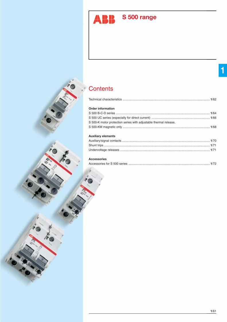
1/61ABB SACE
1
Contents
Technical characteristics .......................................................................................................1/62
Order information
S 500 B-C-D series ............................................................................................................... 1/64
S 500 UC series (especially for direct current) ..................................................................... 1/66
S 500-K motor protection series with adjustable thermal release,
S 500-KM magnetic only ....................................................................................................... 1/68
Auxiliary elements
Auxiliary/signal contacts ........................................................................................................1/70
Shunt trips ............................................................................................................................. 1/71
Undervoltage releases ..........................................................................................................1/71
Accessories
Accessories for S 500 series ................................................................................................ 1/72
S 500 range
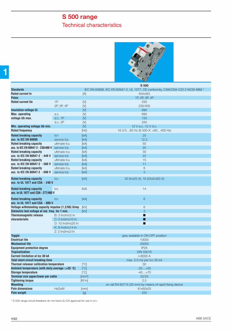
1/62 ABB SACE
1
S 500 rangeTechnical characteristics
S 500Standards IEC EN 60898, IEC EN 60947-2, UL 1077, CE conformity, CAN/CSA-C22.2 N235-M89 *Rated current In [A] 6≤In≤63Poles 1P, 2P, 3P, 4PRated current Ue 1P [V] 230
2P, 3P, 4P [V] 230/400Insulation voltage Ui [V] 690Max. operating a.c. [V] 690voltage Ub max. d.c. 1P [V] 125
d.c. 2P [V] 250Min. operating voltage Ub min. [V] 12 V a.c.-12 V d.c.Rated frequency [Hz] 16 2/3…60 Hz (S 500-X: >60…400 Hz)
Rated breaking capacity Icn [kA] 25acc. to IEC EN 60898 service Ics [kA] 12.5Rated breaking capacity ultimate Icu [kA] 50acc. to IEC EN 60947-2 - 230/400 V service Ics [kA] 25Rated breaking capacity ultimate Icu [kA] 30acc. to IEC EN 60947-2 - 440 V service Ics [kA] 22Rated breaking capacity ultimate Icu [kA] 15acc. to IEC EN 60947-2 - 500 V service Ics [kA] 11Rated breaking capacity ultimate Icu [kA] 6acc. to IEC EN 60947-2 - 690 V service Ics [kA] 3
Rated breaking capacity Icc [kA] 30 (In≤25 A); 18 (25≤In≤63 A)acc. to UL 1077 and CSA - 240 V
Rated breaking capacity Icc [kA] 14acc. to UL 1077 and CSA - 277/480 V
Rated breaking capacity Icc [kA] 6acc. to UL 1077 and CSA - 600 VVoltage withstanding capacity impulse (1,2/50) Uimp [kV] 6Dielectric test voltage at ind. freq. for 1 min. [kV] 3Thermomagnetic release B: 3 In≤Im≤5 In
characteristic C: 5 In≤Im≤10 In
D: 10 In≤Im≤20 In
K: 8 In≤Im≤14 InZ: 2 In≤Im≤3 In
Toggle grey sealable in ON-OFF positionElectrical life 10000Mechanical life 20000Equipment protection degree IP2XTropicalization DIN 50016Current limitation at Icc 30 kA I<8000 ATotal short-circuit breaking time max. 2.5 ms per Icc 30 kAThermal releaser calibration temperature [°C] 30Ambient temperature (with daily average ≤+35 °C) [°C] -25…+55Storage temperature [°C] -40…+70Terminal size upper/lower per cable [mm2] 25/25Tightening torque [N*m] 2.5Mounting on rail EN 60715 (35 mm) by means of rapid fixing devicePole dimensions HxDxW [mm] 91x92x25Pole weight [g] 250
* S 500 range circuit-breakers do not have UL/CA approval for use in d.c.

1/63ABB SACE
1
S 500 rangeTechnical characteristics
S 500 UC-B S 500 UC-K S 500-K S 500-KMStandards IEC EN 60898, IEC EN 60947-2, UL 1077, CE conformity,
CAN/CSA-C22.2 N235-M89 *
Rated current In fixed [A] 6≤In≤63 – – – 1.6≤In≤75adjustable [A] – 0.1≤In≤45 0.1≤In≤11 11 ≤In≤45 –
Poles 1P, 2P, 3P, 4P 1P, 2P, 3P, 4P 1P, 2P, 3P 3PRated current Ue 1P [V] 250 V d.c. 230 230
2P [V] 500 V d.c. 230/400 230/4003P, 4P [V] 750 V d.c. 230/400 230/400
Insulation voltage Ui [V] 690 690 690Max. operating voltage Ub max. a.c. [V] 690 690 690
d.c. 1P [V] 250 V d.c. 125 V d.c. 125 V d.c.d.c. 2P [V] 500 V d.c. 250 V d.c. 250 V d.c.d.c. 3P, 4P [V] 750 V d.c. 250 V d.c. 250 V d.c.
Min. operating voltage Ub min. [V] 12 V a.c. - 12 V d.c. 12 V a.c. - 12 V d.c. 12 V a.c. - 12 V d.c.Rated frequency [Hz] 16 2/3 …60 Hz (S 500-X:> 60 … 400 Hz)
Rated breaking capacity ultimate Icu [kA] – – 50 30 25IEC EN 60947-2 - 230 /400 V service Ics [kA] – – 30 25 –
Rated breaking capacity ultimate Icu [kA] – – 30 25 –IEC EN 60947-2 - 440 V service Ics [kA] – – 22 22 –
Rated breaking capacity ultimate Icu [kA] – – 20 15 –IEC EN 60947-2 - 500 V service Ics [kA] – – 15 11 –
Rated breaking capacity ultimate Icu [kA] – – 6 6 –IEC EN 60947-2 - 690 V service Ics [kA] – – 3 3 –
Rated breaking capacity Icc [kA] – – 30 18 –acc. to UL 1077 and CSA - 240 VRated breaking capacity Icc [kA] – – 14 14 –acc. to UL 1077 and CSA - 277/480 VRated breaking capacity Icc [kA] – – 6 6 –acc. to UL 1077 and CSA - 600 V
Rated breaking capacity [kA] 30 30 – – –acc. to UL 1077, CSA and IEC EN 60947-2 - 250 V d.c. (1P),500 V d.c.(2P), 750 V d.c. (3P), L/R 15 ms
Thermomagnetic release B: 3 In≤Im≤5 In – – – –characteristic K: 8 In≤Im≤14 In ** – –
magnetic only KM:8 In≤Im≤14 In ** – – – –
Toggle grey sealable in ON-OFF positionElectrical life 10000Mechanical life 20000Equipment protection degree IP2XTropicalization DIN 50016Current limitation at Icc 30 kA I<3000 A I< 8000 ATotal short-circuit breaking time max. 2.5 ms per Icc 30 kAThermal releaser calibration temperature [°C] 30 40 – 40 – –Ambient temperature (with daily average ≤ +35°C) [°C] -25…+55Storage temperature [°C] -40…+70Terminal size upper/lower per cable [mm2] 25/25Tightening torque [N*m] 2.5Mounting on rail EN 60715 (35 mm) by means of rapid fixing devicePole dimensions HxDxW [mm] 91x92x25Pole weight [g] 250* S 500 range circuit-breakers do not have UL/CA approval for use in d.c.** K and KM curves magnetic tripping range: 8 In<Im<10 In (d.c./a.c., In<0.21); 10 In<Im<12 In (d.c./a.c., 0.2<In<0.42); 12 In<Im<14 In (d.c./a.c., In>0.38)

1/64 ABB SACE
1
S 500 rangeS 500 B-C-D series
B (Im=3…5 In); C (Im=5…10 In)
D (Im=10…20 In)
Tripping characteristics
Application: tertiary and industrial
RCBO version
F 500
Rated currents CodeIn Characteristic[A] B C D
1P - S 501 type
6 EI 060 4 EI 100 8 -10 EI 061 2 EI 101 6 EI 366 5
13 EI 062 0 EI 102 4 EI 027 3
16 EI 063 8 EI 103 2 EI 028 1
20 EI 064 6 EI 104 0 EI 029 9
25 EI 065 3 EI 105 7 EI 030 7
32 EI 066 1 EI 106 5 EI 031 5
40 EI 067 9 EI 107 3 EI 032 3
50 EI 068 7 EI 108 1 EI 033 1
63 EI 069 5 EI 109 9 EI 034 9
2P - S 502 type
6 EI 070 3 EI 110 7 -10 EI 071 1 EI 111 5 EI 367 3
13 EI 072 9 EI 112 3 EI 035 6
16 EI 073 7 EI 113 1 EI 036 4
20 EI 074 5 EI 114 9 EI 037 2
25 EI 075 2 EI 115 6 EI 038 0
32 EI 076 0 EI 116 4 EI 039 8
40 EI 077 8 EI 117 2 EI 040 6
50 EI 078 6 EI 118 0 EI 041 4
63 EI 079 4 EI 119 8 EI 042 2
TEP
M00
73TE
PM
0074
RCD blocks
DDA 500 63 A
The DDA 500 RCD blocks cannot be connected to S 500 B-C-D In=6 A circuit-breakers
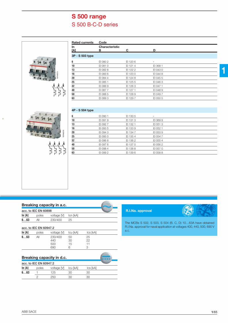
1/65ABB SACE
1
Breaking capacity in a.c.acc. to IEC EN 60898
In [A] poles voltage [V] Icn [kA]
6...63 All 230/400 25
acc. to IEC EN 60947.2
In [A] poles voltage [V] Icu [kA] Ics [kA]
6...63 All 230/400 50 25440 30 22500 15 11690 6 3
Breaking capacity in d.c.acc. to IEC EN 60947.2
In [A] poles voltage [V] Icu [kA] Ics [kA]
6...63 1 125 30 30
2 250 30 30
Rated currents CodeIn Characteristic[A] B C D
3P - S 503 type
6 EI 080 2 EI 120 6 -10 EI 081 0 EI 121 4 EI 368 1
13 EI 082 8 EI 122 2 EI 043 0
16 EI 083 6 EI 123 0 EI 044 8
20 EI 084 4 EI 124 8 EI 045 5
25 EI 085 1 EI 125 5 EI 046 3
32 EI 086 9 EI 126 3 EI 047 1
40 EI 087 7 EI 127 1 EI 048 9
50 EI 088 5 EI 128 9 EI 049 7
63 EI 089 3 EI 129 7 EI 050 5
4P - S 504 type
6 EI 090 1 EI 130 5 -10 EI 091 9 EI 131 3 EI 369 9
13 EI 092 7 EI 132 1 EI 051 3
16 EI 093 5 EI 133 9 EI 052 1
20 EI 094 3 EI 134 7 EI 053 9
25 EI 095 0 EI 135 4 EI 054 7
32 EI 096 8 EI 136 2 EI 055 4
40 EI 097 6 EI 137 0 EI 056 2
50 EI 098 4 EI 138 8 EI 057 0
63 EI 099 2 EI 139 6 EI 058 8
S 500 rangeS 500 B-C-D series
TEP
M00
75
TEP
M00
76
The MCBs S 502, S 503, S 504 (B, C, D) 10…63A have obtainedR.I.Na. approval for naval application at voltages 400, 440, 500, 690 Va.c.
R.I.Na. approval

1/66 ABB SACE
1
S 500 rangeS 500 UC series (especially for direct current)
B (Im=3…5 In); K (Im=8…14 In)
Tripping characteristics
Application: protection of circuits in d.c.
Rated currents CodeIn Characteristic[A] B K
1P - S 501 UC type
6 EI 315 2
10 EI 316 0
13 EI 317 8
16 EI 318 6
20 EI 319 4
25 EI 320 2
32 EI 321 0
40 EI 322 4
50 EI 323 6
63 EI 324 6
2P - S 502 UC type
6 EI 325 1
10 EI 326 9
13 EI 327 7
16 EI 328 5
20 EI 329 3
25 EI 330 1
32 EI 331 9
40 EI 332 7
50 EI 333 5
63 EI 334 3
TEP
M00
78
TEP
M00
77

1/67ABB SACE
1
Breaking capacity in d.c.acc. to IEC EN 60947.2/UL077/CAN CSA-C22.2 N235-M89
In [A] poles voltage [V] Icu [kA] Ics [kA]
0.1…63 1P 250 30 30
2P 500 30 30
3P 750 30 30In alternating current they maintain the same performance as S 500 B, K
S 500 rangeS 500 UC series (especially for direct current)
Rated currents CodeIn Characteristic[A] B K
3P - S 503UC type
6 EI 335 0
10 EI 336 8
13 EI 337 6
16 EI 338 4
20 EI 339 2
25 EI 340 0
32 EI 341 8
40 EI 342 6
50 EI 343 4
63 EI 344 2
1P, 2P, 3P, 4P S 501 UC-K, S 502 UC-K, S 503 UC-K and S 504 UC-K motor protection with adjustable
thermal types*
0.1 - 0.16 on request
... on request
38 - 45 on request* The adjustment ranges are the same as those for the S 500-K circuit-breakers
TEP
M00
79
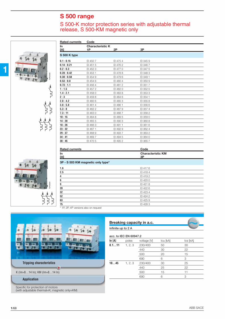
1/68 ABB SACE
1
Breaking capacity in a.c.infinite up to 2 A
acc. to IEC EN 60947.2
In [A] poles voltage [V] Icu [kA] Ics [kA]
0.1...11 1, 2, 3 230/400 50 30
440 30 22
500 20 15
690 6 3
10...45 1, 2, 3 230/400 30 25
440 25 22
500 15 11
690 6 3
S 500 rangeS 500-K motor protection series with adjustable thermalrelease, S 500-KM magnetic only
K (Im=8…14 In); KM (Im=8…14 In)
Tripping characteristics
Application
Rated currents CodeIn Characteristic K[A] 1P 2P 3P
S 500 K type
0.1 - 0.15 EI 450 7 EI 475 4 EI 345 9
0.14 - 0.21 EI 451 5 EI 476 2 EI 346 7
0.2 - 0.3 EI 452 3 EI 477 0 EI 347 5
0.28 - 0.42 EI 453 1 EI 478 8 EI 348 3
0.38 - 0.58 EI 454 9 EI 479 6 EI 349 1
0.53 - 0.8 EI 454 6 EI 480 4 EI 350 9
0.73 - 1.1 EI 456 4 EI 481 2 EI 351 7
1 - 1.5 EI 457 2 EI 482 0 EI 352 5
1.4 - 2.1 EI 458 0 EI 483 8 EI 353 3
2 - 3 EI 459 8 EI 484 6 EI 354 1
2.8 - 4.2 EI 460 6 EI 485 3 EI 355 8
3.8 - 5.8 EI 461 4 EI 486 1 EI 356 6
5.3 - 8 EI 462 2 EI 487 9 EI 357 4
7.3 - 11 EI 463 0 EI 488 7 EI 358 2
10 - 15 EI 464 8 EI 489 5 EI 359 0
14 - 20 EI 465 5 EI 490 3 EI 360 8
18 - 26 EI 466 3 EI 491 1 EI 361 6
23 - 32 EI 467 1 EI 492 9 EI 362 4
29 - 37 EI 468 9 EI 493 7 EI 363 2
34 - 41 EI 469 7 EI 494 5 EI 364 0
38 - 45 EI 470 5 EI 495 2 EI 365 7
Rated currents CodeIn Characteristic KM[A] 3P
3P - S 503 KM magnetic only type*
1.6 EI 417 6
2.5 EI 418 4
4 EI 419 2
6 EI 420 0
9 EI 421 8
20 EI 422 6
32 EI 423 4
52 EI 424 2
63 EI 425 9
75 EI 428 3* 1P, 2P, 4P versions also on request
Specific for protection of motors(with adjustable thermal=K; magnetic only=KM)
TEP
M00
80TE
PM
0081

1/69ABB SACE
1
For the S 500 range of circuit-breakers, shunt trips,undervoltage releases and con-tacts (auxiliary and signal) areavailable.
Only the auxiliary contacts canbe mounted by the installer; theundervoltage releases andshunt trips are installed directlyat the factory and, for this rea-son, cannot be ordered sepa-rately.
Four shunt trips for voltages of24 V a.c./d.c, 110 V a.c./d.c,220 V a.c./d.c, and 400 V a.c./d.c, and eight undervoltage re-
S 500 rangeAuxiliary elements
leases for voltages equal to24 V a.c., 110 V a.c., 230 Va.c., 400 V a.c., 24 V d.c.,110 V d.c., 230 V d.c., 400 Vd.c. are available.
These auxiliary elements canalso be mounted on the corres-ponding RCBO version (F 500series).
The S 500 circuit-breakers arealso equipped with a rotarydrive with the possibility of se-lection from different rotary han-dle.
TEP
M01
435
S5-HCONTATTOAUSILIARIO
S5-SCONTATTO DI
SEGNALAZIONE
S5-UABOBINA DI MINIMA
TENSIONE*oppureS5-AL
BOBINA A LANCIO DICORRENTE*
INTERRUTTOREAUTOMATICO
S 500
BLOCCODIFFERENZIALEDDA 500
S5-Hoppure
S5-S
S5-HCONTATTOAUSILIARIO
S5-Hoppure
S5-S
* Assemblati in fabbrica
Example of combination of S 500 series circuit-breakers with auxiliary elements (maximum configuration)
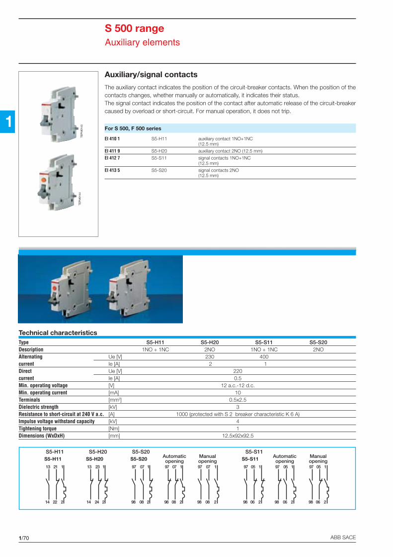
1/70 ABB SACE
1
Auxiliary/signal contacts
The auxiliary contact indicates the position of the circuit-breaker contacts. When the position of thecontacts changes, whether manually or automatically, it indicates their status.The signal contact indicates the position of the contact after automatic release of the circuit-breakercaused by overload or short-circuit. For manual operation, it does not trip.
For S 500, F 500 series
EI 410 1 S5-H11 auxiliary contact 1NO+1NC(12.5 mm)
EI 411 9 S5-H20 auxiliary contact 2NO (12.5 mm)
EI 412 7 S5-S11 signal contacts 1NO+1NC(12.5 mm)
EI 413 5 S5-S20 signal contacts 2NO(12.5 mm)
Technical characteristicsType S5-H11 S5-H20 S5-S11 S5-S20Description 1NO + 1NC 2NO 1NO + 1NC 2NOAlternating Ue [V] 230 400current Ie [A] 2 1Direct Ue [V] 220current Ie [A] 0.5Min. operating voltage [V] 12 a.c.-12 d.c.Min. operating current [mA] • 10Terminals [mm2] 0.5x2.5Dielectric strength [kV] 3Resistance to short-circuit at 240 V a.c. [A] 1000 (protected with S 2 breaker characteristic K 6 A)Impulse voltage withstand capacity [kV] 4Tightening torque [Nm] 1Dimensions (WxDxH) [mm] 12.5x92x92.5
S 500 rangeAuxiliary elements
TEP
M01
43TE
PM
0144
Automaticopening
97 07
98 08
1
2
97 07
98 08
1
2
S5-S20
13 23
14 24
1
2
S5-H11
13 21
14 22
1
2
S5-H20
97 07
98 08
1
2
Manualopening S5-S11
97 05
98 06
1
2
97 05
98 06
1
2
97 05
98 06
1
2
Automaticopening
Manualopening
S5-H11 S5-H20 S5-S20 S5-S11

1/71ABB SACE
1
Shunt trips
Consumption on release 130 VA-120 W.
Code Type Description
For S 500 series
* S5 AL 24V shunt trip24 V a.c./d.c.
* S5 AL 110V shunt trip110 V a.c./d.c.
* S5 AL 220V shunt trip220 V a.c./d.c.
* S5 AL 400V shunt trip400 V a.c./d.c.
* The S5 AL type shunt trips must be ordered with the S 500 circuit-breaker, since they are installed directly in the factory (theycannot be installed by the customer).
Undervoltage releases
Consumption max. 3.5 VA - 3.5 W.
Code Type Description
For S 500 series
* S5-UA 24V ca 24 V c.a. undervoltage release(1 module)
* S5-UA 110V ca 110 V a.c. undervoltage release(1 module)
* S5-UA 230V ca 230 V a.c. undervoltage release(1 module)
* S5-UA 400V ca 400 V a.c. undervoltage release(1 module)
* S5-UA 24V cc 24 V d.c. undervoltage release(1 module)
* S5-UA 110V cc 110 V d.c. undervoltage release(1 module)
* S5-UA 230V cc 230 V d.c. undervoltage release(1 module)
* S5-UA 400V cc 400 V d.c. undervoltage release(1 module)
* The S5 UA undervoltage releases must be ordered with the S 500 circuit-breaker since they are installed directly in the factory(they cannot be installed by the customer).
S 500 rangeAuxiliary elements
1
2
C1
C2
S5 AL
Montaggio solo a sinistra

1/72 ABB SACE
1
S 500 rangeAccessories
For S 500 and F 500 series
EI 409 3 S500 RD3 rotary control knob for 1P, 2P, 3P S 500 circuit-breakers*
EI 426 7 S500 RD4 rotary control knob for 4P S 500 circuit-breakers*
* When using S 503 three-pole circuit-breakers with undervoltage releases or shunt trips, the rotary control knobto order is S 500 RD4
EI 427 5 S500 H2B1 rotary control knob; black IP65 with interlockON, padlock possible in OFF position
EI 437 4 S500 H2Y1 rotary control knob; red/yellow IP65 with interlockON, padlock possible in OFF position
EI 438 2 S500 H2B2 rotary control knob; black IP65 with interlockON, padlock possible in OFF position with manual release
EI 439 0 S500 H2Y2 rotary control knob; red/yellow IP65 with interlockON, padlock possible in OFF position with manual release
EI 442 4 S500 HP2B emergency plate - black
EI 443 2 S500 HP2Y emergency plate - red/yellow
EI 440 8 S500 H8B rotary control knob; black IP65 withinterlock ON, padlock possible in OFF position withmanual release
EI 441 6 S500 H8Y rotary control knob for circuit-breakers; red/yellow IP65 withinterlock ON, padlock possible in OFFposition with manual release
EI 416 8 S500 S51 drive shaft L=85 mm
EI 415 0 S500 S52 drive shaft L=180 mm
EI 444 0 S500 S56 drive shaft L=265 mm** Only suitable for EI 440 8 and EI 441 6 knobs
S500 RD3
S500 H2B1S500 H2B2
S500 H8B
S500 H8Y
S500 S51S500 S52S500 S56

1/73ABB SACE
1
S 700 range
Contents
Technical characteristics .......................................................................................................1/74
Order information
S 701, S 702, S 703, S 704 series ........................................................................................ 1/75
Accessories
Accessories for S 700 series ................................................................................................ 1/75

1/74 ABB SACE
1
Breaking capacity in a.c.acc. to IEC EN 60947.2
In [A] poles voltage [V] Icu [kA] Ics [kA]
25...100 1 230 50 25
2 230 50 25400 30 15
3, 4 230 50 25400 30 15
4 500 15 7,5690 10 5
E sel. (Im=5…6,25 In)
Tripping characteristics
Application: industrial, navalThe S 702, S 703 MCBs for naval application have obtained R.I.Na.approval
R.I.Na. approval
Rated current In [A] 25...100Rated current a.c. [V] 400Min. operating voltage [V] 125Electrical life [n°] 4000Mechanical life [n°] 10000Tropicalization at 55°C acc. to DIN 40046 95% URTerminals for cable cage type up to 70 mm2
Self-extinguishing degree V0 thickness 3.2 mmPoles 1P 2P 3P 4PWeight [g] 550 1100 1650 2200
S 700 rangeTechnical characteristics

1/75ABB SACE
1
S 700 rangeS 701, S 702, S 703, S 704 series and accessories
Rated currents CodeIn Characteristic[A] E sel.
1P - S 701 type
25 EG 700 7
35 EG 701 5
50 EG 702 3
63 EG 703 1
80 EG 704 9
100 EG 705 6
2P - S 702 type Naval application
25 EG 706 4 EG 730 4
35 EG 707 2 EG 731 2
50 EG 708 0 EG 732 0
63 EG 709 8 EG 733 8
80 EG 710 6 EG 734 6
100 EG 711 4 EG 735 3
3P - S 703 type Naval application
25 EG 712 2 EG 736 1
35 EG 713 0 EG 737 9
50 EG 714 8 EG 738 7
63 EG 715 5 EG 739 5
80 EG 716 3 EG 740 3
100 EG 717 1 EG 741 1
4P - S 704 type
25 EG 718 9
35 EG 719 7
50 EG 720 5
63 EG 721 3
80 EG 722 1
100 EG 723 9
Accessories for S 700 series
EG 035 8 BT3 plate for assembly on EN50022 rail(1 piece for 1P, 2 pieces for 2P, 3P, 4P)
EG 037 4 KA1 pair of terminal covers(2 pieces per pole)
EG 040 8 SA connection flange and fixing on busbars
EG 041 6 SPA plate for blocking manual opening
EG 042 4 SPB1 transparent plate for blocking operation, for lever position inspection
EG 044 0 SPE toggle locking device, padlock possible
EL 175 6 BA50 transparent label carrier; covers and assorted labels
EG 046 5 EST1 withdrawable kit on NH base (2 pieces per pole)
EG 047 3 EST2 terminal protection for withdrawable version NH base (2 pieces per pole)
TEP
M00
82
TEP
M00
83TE
PM
0084
TEP
M00
85

1/76 ABB SACE
1
2/1ABB SACE
2
Technical detailsand guide to applications
Contents
Tripping characteristics ........................................................................................................2/2
Limitation of specific let-through energy ........................................................................... 2/5
Ip peak current ...................................................................................................................... 2/9
Coordination tables ............................................................................................................ 2/18
Lighting circuit protection .................................................................................................. 2/56
Transformer protection ......................................................................................................2/57
Internal resistances and dissipated power tables ........................................................... 2/59
Influence of ambient temperature on effective capacity and rated current ..................2/61
Variation in alarm thresholds according to network frequency .....................................2/63
Applications in d.c. of standard circuit-breakers ............................................................. 2/63
Examples of maximum voltages allowed between terminals according tonumber of poles and wiring ............................................................................................... 2/64
Examples of high voltages between terminals and earthwith equal voltage between terminals .............................................................................. 2/64
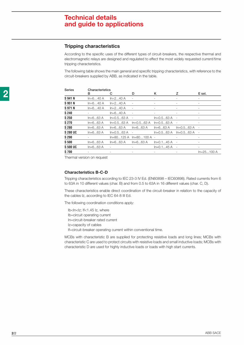
2/2 ABB SACE
2
Technical detailsand guide to applications
Tripping characteristics
According to the specific uses of the different types of circuit-breakers, the respective thermal andelectromagnetic relays are designed and regulated to effect the most widely requested current/timetripping characteristics.
The following table shows the main general and specific tripping characteristics, with reference to thecircuit-breakers supplied by ABB, as indicated in the table.
Series CharacteristicsB C D K Z E sel.
S 941 N In=6…40 A In=2...40 A - - - -
S 951 N In=6…40 A In=2...40 A - - - -
S 971 N In=6…40 A In=2...40 A - - - -
S 240 - In=6...40 A - - - -
S 250 In=6...63 A In=0.5...63 A - In=0.5...63 A - -
S 270 In=6...63 A In=0.5...63 A In=0.5...63 A In=0.5...63 A - -
S 280 In=6...63 A In=6...63 A In=6...63 A In=6...63 A In=0.5...63 A -
S 280 UC In=6...63 A In=0.5...63 A - In=0.5...63 A In=0.5...63 A -
S 290 - In=80...125 A In=80…100 A - - -
S 500 In=6...63 A In=6...63 A In=6...63 A In=0.1...45 A - -
S 500 UC In=6...63 A - - In=0.1...45 A - -
S 700 - - - - - In=25...100 A
Thermal version on request
Characteristics B-C-DTripping characteristics according to IEC 23-3 IV Ed. (EN60898 – IEC60898). Rated currents from 6to 63A in 10 different values (char. B) and from 0.5 to 63A in 16 different values (char. C, D).
These characteristics enable direct coordination of the circuit-breaker in relation to the capacity ofthe cables Iz, according to IEC 64-8 III Ed.
The following coordination conditions apply:
Ib<In<Iz; If<1.45 Iz, whereIb=circuit operating currentIn=circuit-breaker rated currentIz=capacity of cablesIf=circuit-breaker operating current within conventional time.
MCBs with characteristic B are supplied for protecting resistive loads and long lines; MCBs withcharacteristic C are used to protect circuits with resistive loads and small inductive loads; MCBs withcharacteristic D are used for highly inductive loads or loads with high start currents.

2/3ABB SACE
2
Technical detailsand guide to applications
Tripping characteristic B C D
Standard IEC 23-3 IV ed. IEC 23-3 IV ed. IEC 23-3 IV ed.
Rated current In 6…63 A 0.5…63 A 0.5…63 A
Thermal tripTest currents
non-tripping current Inf 1.13 In 1.13 In 1.13 In
tripping time >1 h >1 h >1 h
tripping current If 1.45 In 1.45 In 1.45 In
tripping time <1 h <1 h <1 h
Electro-magnetic tripTest currents
non-tripping current Im1 3 In 5 In 10 In
tripping time >0.1 s >0.1 s >0.1 s
tripping current Im2 5 In 10 In 20 In
tripping time <0.1 s <0.1 s <0.1 s
Characteristics B, C, D Characteristics, magnetic only
multiples of rated current
Sec
onds
Min
utes
1 1.5 2 3 4 5 6 8 10 15 20 30
0.01
0.02
0.040.06
0.1
0.2
0.40.6
1
2
46
10
20
401
2
46
10
20
4060
120
1.13
2.55
1.45
10 20 30
90
45
30
15
8
B C D
> 63
≤ 63
> 32
≤ 32
multiples of rated current
Sec
onds
Min
utes
1 1.5 2 3 4 5 6 8 10 15 20 30
0.01
0.02
0.040.06
0.1
0.2
0.40.6
1
2
46
10
20
401
2
46
10
20
4060
120
1.05
1.2
16
14 18

2/4 ABB SACE
2
Technical detailsand guide to applications
Characteristics K-Z-E selectiveTripping characteristics according to DINVDE 0660. Rated currents from 0.5 to 63 A, in 16 differentvalues.
They are used to control and protect inductive circuits, power suppliers for semi-conductor electroniccircuits and secondary measurement circuits, in the commercial and industrial sectors.
Tripping characteristic K Z E selective
Standard DIN VDE 0660 DIN VDE 0660 DIN VDE 06609.82 part 1 9.82 part 1
Rated current In 0.5…63 A 0.5…63 A 25…100 A
Thermal tripTest currents
non-tripping current Inf 1.05 In 1.05 In 1.05 In
tripping time >2 h >2 h >2 h
tripping current If 1.2 In 1.2 In 1.2 In
tripping time <2 h <2 h <2 h
Electro-magnetic trip non-tripping current Im1 8 In 2 In 5 In
tripping time >0.2 s >0.2 s >0.3 s
tripping current Im2 14 In 3 In 6.25 In
tripping time <0.2 s <0.2 s <0.3 s
Characteristics K, Z Characteristics S selective
multiples of rated current
Sec
onds
Min
utes
1 1.5 2 3 4 5 6 8 10 15 20 30
0.01
0.02
0.040.06
0.1
0.2
0.40.6
1
2
46
10
20
401
2
46
10
20
4060
120
1.05
1.2
10 12 18
Z K
Sec
onds
Min
utes
100
6040
20
10
6
4
2
1
40
20
10
6
4
2
1
0.6
0.4
0.2
0.1
0.06
0.04
0.02
0.01
2 3 4 5 6 8 10 20 30 40 50
Trip
ping
tim
e de
lay
multiples of rated current
1
1.051.2
multiples of rated current
Sec
onds
Min
utes
1 1.5 2 3 4 5 6 8 10 15 20 30
0.01
0.02
0.040.06
0.1
0.2
0.40.6
1
2
46
10
20
401
2
46
10
20
4060
120
1.05
1.2
10 14 18
Z K

2/5ABB SACE
2
Technical detailsand guide to applications
Limitation of specific let-through energy
Tripping of an installation circuit by circuit-breaker when there is a short-circuit requires a certainamount of time depending on the characteristics of the circuit-breaker and the entity of the short-circuit current. During this period of time, some or all of the short-circuit current flows into the installation;the parameter I2t defines the “specific let-through energy”, ie. the specific energy that the breakerallows through when there is a short-circuit current Icc during the tripping time t.
In this way, we can determine the capacity of a circuit-breaker to limit, ie. break high currents up tothe rated breaking power of the device, by reducing the peak value of the above-mentioned currentsto a value which is considerably lower than the estimated current.
This can be achieved using mechanisms which open very rapidly and have the following advantages:
- they limit the thermal and dynamic effects both on the circuit-breaker and on the protected circuit;
- they reduce the dimensions of the current-limiting circuit-breaker without reducing breaking capacity;
- they considerably reduce ionized gases and sparklers emitted during the short-circuit and thereforethey avoid the danger of ignition and fires.
I
U
I2
tv
KMi
iK
uM
uBt = 0
2
Interruttore limitatore
KM
t
t
t
t = 0
tv
I
U
I2
1
iK
uMuB
Interruttore non limitatore
OE
PM
0092
Non-current limiting circuit-breaker
Oscillogram of short-circuitbreaks on two circuit-breakers:
1 = traditional non-current limiting circuit-breaker
2 = current limiting circuit-breakeruB = arc voltage (red)uM = rest voltage (blue)
Current limiting circuit-breaker
Short-circuit currentred = effective short-circuit current squaredblue = estimated short-circuit current squared
(shunted circuit-breaker)iKM = maximum values of symmetrical
component of short-circuit currentsquared
shaded inred = specific let-through energy in two cases
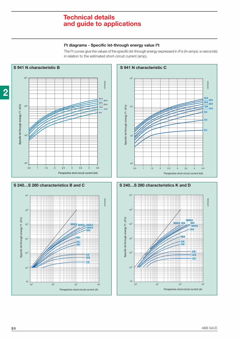
2/6 ABB SACE
2
Technical detailsand guide to applications
I2t diagrams - Specific let-through energy value I2tThe I2t curves give the values of the specific let-through energy expressed in A2s (A=amps; s=seconds)in relation to the estimated short-circuit current (amp).
S 941 N characteristic B
S 240…S 280 characteristics B and C S 240…S 280 characteristics K and D
OE
PM
0095
OE
PM
0096
OE
PM
0093
OE
PM
0094
S 941 N characteristic C
Spe
cific
let t
hrou
gh e
nerg
y I2 t
(A
2 s)
103
104
105
102
Perspective short-circuit current (kA)
10 A
0.5 1 1.5 2 2.5 3 3.5 4 4.5
6 A
20 A16 A
32 A25 A
40 A
Spe
cific
let-
thro
ugh
ener
gy I2 t
(A
2 s)
103
104
105
102
Perspective short-circuit current (kA)
4 A
2 A
10 A
0.5 1 1.5 2 2.5 3 3.5 4 4.5
6 A
20 A16 A
32 A25 A
40 A
Spe
cific
let-
thro
ugh
ener
gy I2 t
(A
2 s)
102
103
104
105
106
107
10
Perspective short-circuit current (A)
2 A
1.6 A
1 A
3 A
4 A
6 A
10 A13/16 A20/25 A50/63 A 32/40 A
105104102 103
Spe
cific
let-
thro
ugh
ener
gy I2 t
(A
2 s)
102
103
104
105
106
107
10
Perspective short-circuit current (A)
2 A
1.6 A
1 A
3 A
4 A
6/8 A
10 A
13/16 A
20 A50/63 A
28/32 A
40 A
105104102 103

2/7ABB SACE
2
Technical detailsand guide to applications
S 280 characteristic Z S 290 characteristic C, D
S 500 characteristics B, C and D
OE
PM
0099
OE
PM
0100
OE
PM
0097
OE
PM
0098
105
Spe
cific
let-
thro
ugh
ener
gy I2 t
(A
2 s)
104102
102
103
104
105
106
107
10
Perspective short-circuit current (A)
103
2 A
1.6 A
1 A
3 A
4 A
6 A
10 A13/16 A
50/63 A 32/40 A 20/25 A
Spe
cific
let-
thro
ugh
ener
gy I2 t
(A2 s)
Perspective short-circuit current (A)
104103103
104
105
106
107
1.5.104
100/125 A
80 A
Spe
cific
let-
thro
ugh
ener
gy I2 t
(A
2 s)
104
105
106
103
Perspective short-circuit current (A)
40 A25 A
16 A
105104102 103
13 A
Spe
cific
let-
thro
ugh
ener
gy I2 t
(A
2 s)
104
105
106
103
Perspective short-circuit current (A)
63 A 50 A
105104102 103

2/8 ABB SACE
2
Technical detailsand guide to applications
S 700 characteristic E selective
S 500 K - S 500 KM
S 500 K - S 500 KM
OE
PM
0103
OE
PM
0104
OE
PM
0102
OE
PM
0101
Spe
cific
let-
thro
ugh
ener
gy I2 t
(A
2 s)
10-1
100
101
10-2
Perspective short-circuit current (A)
10410310 102 105
102
0.1…0.15 A
0.14…0.21 A
0.2…0.3 A
0.28…0.42 A
0.38…0.58 A
0.53…0.80 A
0.73…1.1 A
Spe
cific
let-
thro
ugh
ener
gy I2 t
(A
2 s)
102
103
104
101
perspective short-circuit current (A)
10410310 102 105
105
1…1.5 A
2.8…4.2 A
1.4…2.1 A
2…3 A
3.8…5.8 A
5.3…8 A
7.3…11 A
25 A
35 A
50 A
63 A
80 A
100
A
101 2 3 4 6 8 102 2 3 4 6 8 103 2 3 4 6 8 104 2 3103
2
34
6
104
8
2
34
6
2
105
34
68
106
2
8
I =
n
I =n
25 A35 A50 A63 A ... 100 A
100
80
63
50
35
25
5SE
C.
Perspective short-circuit current Icc (A)
Spe
cific
let-
thro
ugh
ener
gy I
t (
A s
.)2
2
Spe
cific
let-
thro
ugh
ener
gy I2 t
(A
2 s)
103
104
105
102
Perspective short-circuit current (A)
10…15 A
105104102 103
18…26 A
29…37 A

2/9ABB SACE
2
Ip peak current
With reference to IEC 17-13/1 and 23-51 relative to the short-circuit withstand test, the limited peakcurrent values corresponding to the ultimate breaking capacity Icu (EN 60947-2) are shown below.
Series In [A] Icu [kA] Ip [kA]
S 941 N 2...40 6 3.5
S 951 N 2...40 10 6
S 971 N 2...40 15 9
S 240 6...40 6 4
S 250 0.5...63 10 6
S 270 0.5...63 15 9
S 280 6...63 25/15 10
S 290 80...125 15 11
S 500 6...63 50 9.5
6000
90001000011000
15000 IEC 17-13/1 Standard limit
S 250
S 270S 280
S 290
In: ≤ 63 A In: ≤ 63 A In: 6...63 A In:80…125 A
Ip [A]
Icu: 10 kA Icu: 15 kA Icu: 25/15 kA Icu: 15 kA
S 500
Icu: 50 kAIEC EN 60947-2
S 240
Icu: 6 kA
4000
In: ≤ 40 A In: ≤ 63 A
S 951 N
S 971 N
In: ≤ 40 A In: ≤ 40 A
Icu: 10 kA Icu: 15 kA
S 941 N
Icu: 6 kA
In: ≤ 40 A
OE
PM
0105
Technical detailsand guide to applications

2/10 ABB SACE
2
S 941 N characteristic C - 230 V
Technical detailsand guide to applications
S 941 N characteristic B - 230 V
Limitation curves
Ip [kA]
10
0
20
50
0.2
0.5
100
0Is [kA]
0.2 0.5 1 2 5 10 20 50 100
1
2
5
10A
32A
40A
25A
20A
16A
Ip [kA]
10
0
20
50
0.2
0.5
100
0Is [kA]
0.2 0.5 1 2 5 10 20 50 100
1
2
5
10 A
6 A
4 A
2 A
32 A
40 A
25 A
20 A
16 A

2/11ABB SACE
2
S 240 characteristic C - 3P, 4P 400 V
Technical detailsand guide to applications
S 250 characteristic B - 3P, 4P 400 V
Ip [kA]
10
0
20
50
0.2
0.5
100
0Is [kA]
0.2 0.5 1 2 5 10 20 50 100
1
2
5
13 A
6 A
8 A
10 A
50 A
63 A
32 A
40 A
25 A
20 A
16 A
Ip [kA]
10
0
20
50
0.2
0.5
100
0Is [kA]
0.2 0.5 1 2 5 10 20 50 100
1
2
5
13 A
6 A
8 A
10 A
32 A
40 A
25 A
20 A
16 A

2/12 ABB SACE
2
S 250 characteristic C - 3P, 4P 400 V
Technical detailsand guide to applications
S 250 characteristic K - 3P, 4P 400 V
Ip [kA]
10
0
20
50
0.2
0.5
100
0Is [kA]
0.2 0.5 1 2 5 10 20 50 100
1
2
5
4 A
3 A
2 A
1.6 A
1 A
0.5 A
13 A
6 A
10 A
50 A
63 A
8 A
32 A
40 A
25 A
20 A
16 A
Ip [kA]
10
0
20
50
0.2
0.5
100
0Is [kA]
0.2 0.5 1 2 5 10 20 50 100
1
2
5
4 A
3 A
2 A
1.6 A
1 A
0.5 A
6 A
10 A
50 A
63 A
8 A
32 A
40 A
25 A
16 A
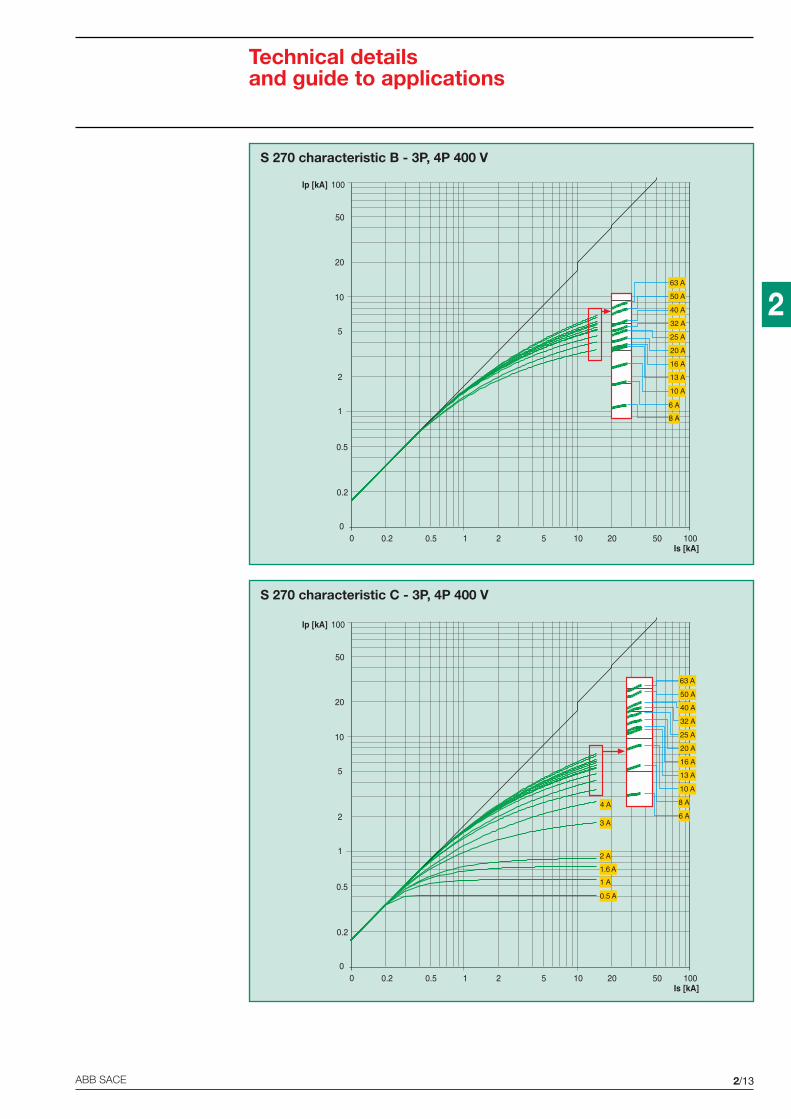
2/13ABB SACE
2
S 270 characteristic B - 3P, 4P 400 V
Technical detailsand guide to applications
S 270 characteristic C - 3P, 4P 400 V
Ip [kA]
10
0
20
50
0.2
0.5
100
0Is [kA]
0.2 0.5 1 2 5 10 20 50 100
1
2
5
13 A
6 A
8 A
10 A
50 A
63 A
32 A
40 A
25 A
20 A
16 A
Ip [kA]
10
0
20
50
0.2
0.5
100
0Is [kA]
0.2 0.5 1 2 5 10 20 50 100
1
2
5
4 A
3 A
2 A
1.6 A
1 A
0.5 A
13 A
6 A
10 A
50 A
63 A
8 A
32 A
40 A
25 A
20 A
16 A

2/14 ABB SACE
2
S 270 characteristic D - 3P, 4P 400 V
Technical detailsand guide to applications
S 270 characteristic K - 3P, 4P 400 V
Ip [kA]
10
0
20
50
0.2
0.5
100
0Is [kA]
0.2 0.5 1 2 5 10 20 50 100
1
2
5
4 A
3 A
2 A
1.6 A
1 A
0.5 A
6 A
10 A
50 A
63 A
8 A
32 A
40 A
25 A
16 A
Ip [kA]
10
0
20
50
0.2
0.5
100
0Is [kA]
0.2 0.5 1 2 5 10 20 50 100
1
2
5
4 A
3 A
2 A
1.6 A
1 A
0.5 A
6 A
10 A
50 A
63 A
8 A
32 A
40 A
25 A
16 A
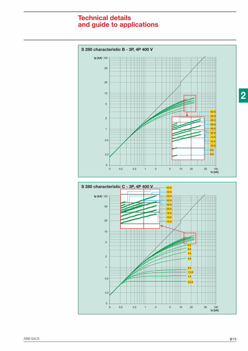
2/15ABB SACE
2
S 280 characteristic B - 3P, 4P 400 V
Technical detailsand guide to applications
S 280 characteristic C - 3P, 4P 400 V
Ip [kA]
10
0
20
50
0.2
0.5
100
0Is [kA]
0.2 0.5 1 2 5 10 20 50 100
1
2
5
10 A
6 A
8 A
40 A
20 A
25 A
50 A
63 A
16 A
32 A
13 A
Ip [kA]
10
0
20
50
0.2
0.5
100
0Is [kA]
0.2 0.5 1 2 5 10 20 50 100
1
2
5
4 A
3 A
2 A
1.6 A
1 A
0.5 A
8 A
6 A
13 A
10 A
50 A
63 A
40 A
25 A
32 A
20 A
16 A

2/16 ABB SACE
2
S 280 characteristic D - 3P, 4P 400 V
Technical detailsand guide to applications
S 280 characteristic K - 3P, 4P 400 V
Ip [kA]
10
0
20
50
0.2
0.5
100
0Is [kA]
0.2 0.5 1 2 5 10 20 50 100
1
2
5
4 A
3 A
2 A
1.6 A
1 A
0.5 A
8 A
6 A
50 A
63 A
40 A
16 A
25 A
10 A
32 A
Ip [kA]
10
0
20
50
0.2
0.5
100
0Is [kA]
0.2 0.5 1 2 5 10 20 50 100
1
2
5
4 A
3 A
2 A
1.6 A
1 A
0.5 A
8 A
6 A
8 A
6 A
50 A
63 A
40 A
25 A
32 A
16 A
10 A
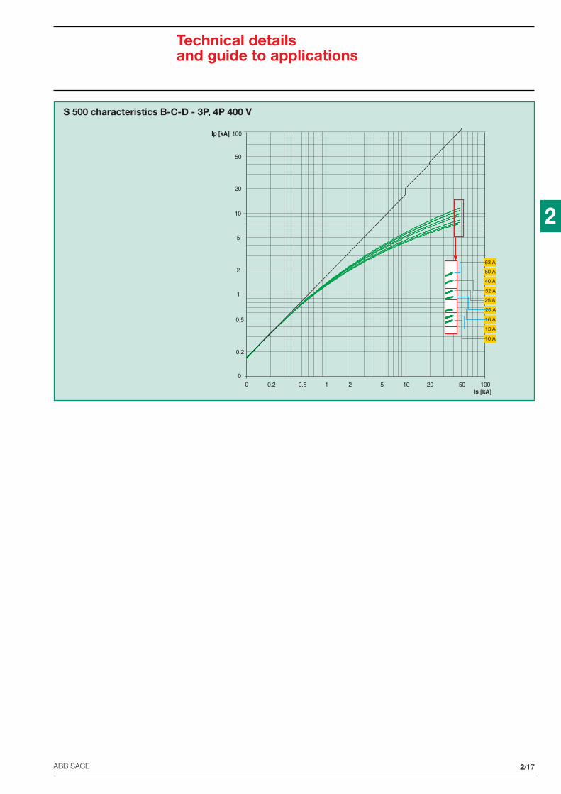
2/17ABB SACE
2
S 500 characteristics B-C-D - 3P, 4P 400 V
Technical detailsand guide to applications
Ip [kA]
10
0
20
50
0.2
0.5
100
0Is [kA]
0.2 0.5 1 2 5 10 20 50 100
1
2
5
13 A
10 A
50 A
63 A
32 A
40 A
25 A
20 A
16 A

2/18 ABB SACE
2
Technical detailsand guide to applications
Coordination tables
Back up protectionThe back up protection tables below indicate the value (in kA, relative to breaking capacity accordingto IEC 60947-2) for which back up protection was in place between the preselected combination ofABB circuit-breakers and in particular between all of the series of modular breakers and the moulded-case circuit-breakers Tmax. The values in the tables refer to a voltage Vn of 400 V a.c.
Selective protectionThe selective protection tables indicate the value (in kA, relative to breaking capacity according to IEC60947-2) for which selective protection was in place between the preselected combination of ABBcircuit-breakers and in particular between all of the series of modular breakers and the moulded-casecircuit-breakers Tmax. The values in the tables represent the maximum selectivity which can be obtainedbetween the breaker upstream and downstream, for a voltage Vn of 400 V a.c.
230V mains supply downstream of a 400V mains supplyTo discover whether or not filtration is possible between devices downstream and upstream in a TTor TNS system with a 400 V mains supply in which 1P+N breakers are installed, consult the filtrationtable for 230 V supply networks.
F N
F N
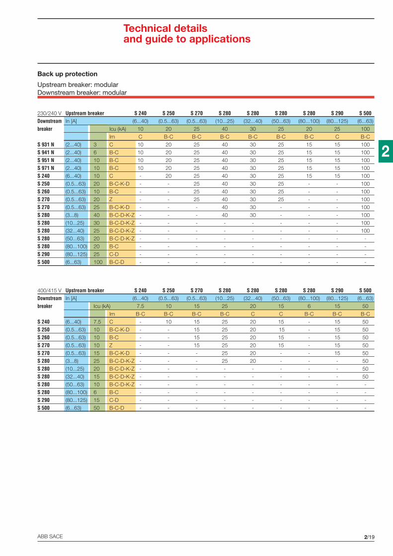
2/19ABB SACE
2
Technical detailsand guide to applications
400/415 V Upstream breaker S 240 S 250 S 270 S 280 S 280 S 280 S 280 S 290 S 500Downstream In [A] (6...40) (0.5...63) (0.5...63) (10...25) (32...40) (50...63) (80...100) (80...125) (6...63)
breaker Icu (kA) 7.5 10 15 25 20 15 6 15 50
Im B-C B-C B-C B-C C C B-C B-C B-C
S 240 (6...40) 7.5 C - 10 15 25 20 15 - 15 50
S 250 (0.5...63) 10 B-C-K-D - - 15 25 20 15 - 15 50
S 260 (0.5...63) 10 B-C - - 15 25 20 15 - 15 50
S 270 (0.5...63) 10 Z - - 15 25 20 15 - 15 50
S 270 (0.5...63) 15 B-C-K-D - - - 25 20 - - 15 50
S 280 (3...8) 25 B-C-D-K-Z - - - 25 20 - - - 50
S 280 (10...25) 20 B-C-D-K-Z - - - - - - - - 50
S 280 (32...40) 15 B-C-D-K-Z - - - - - - - - 50
S 280 (50...63) 10 B-C-D-K-Z - - - - - - - - -
S 280 (80...100) 6 B-C - - - - - - - - -
S 290 (80...125) 15 C-D - - - - - - - - -
S 500 (6...63) 50 B-C-D - - - - - - - - -
230/240 V Upstream breaker S 240 S 250 S 270 S 280 S 280 S 280 S 280 S 290 S 500Downstream In [A] (6...40) (0.5...63) (0.5...63) (10...25) (32...40) (50...63) (80...100) (80...125) (6...63)
breaker Icu (kA) 10 20 25 40 30 25 20 25 100
Im C B-C B-C B-C B-C B-C B-C C B-C
S 931 N (2...40) 3 C 10 20 25 40 30 25 15 15 100
S 941 N (2...40) 6 B-C 10 20 25 40 30 25 15 15 100
S 951 N (2...40) 10 B-C 10 20 25 40 30 25 15 15 100
S 971 N (2...40) 10 B-C 10 20 25 40 30 25 15 15 100
S 240 (6...40) 10 C - 20 25 40 30 25 15 15 100
S 250 (0.5...63) 20 B-C-K-D - - 25 40 30 25 - - 100
S 260 (0.5...63) 10 B-C - - 25 40 30 25 - - 100
S 270 (0.5...63) 20 Z - - 25 40 30 25 - - 100
S 270 (0.5...63) 25 B-C-K-D - - - 40 30 - - - 100
S 280 (3...8) 40 B-C-D-K-Z - - - 40 30 - - - 100
S 280 (10...25) 30 B-C-D-K-Z - - - - - - - - 100
S 280 (32...40) 25 B-C-D-K-Z - - - - - - - - 100
S 280 (50...63) 20 B-C-D-K-Z - - - - - - - - -
S 280 (80...100) 20 B-C - - - - - - - - -
S 290 (80...125) 25 C-D - - - - - - - - -
S 500 (6...63) 100 B-C-D - - - - - - - - -
Back up protection
Upstream breaker: modularDownstream breaker: modular

2/20 ABB SACE
2
Technical detailsand guide to applications
Upstream breaker: moulded-case TmaxDownstream breaker: modular
400 V Upstream breaker T1 T1 T1 T2 T3 T2 T3 T2 T2Downstream Version B C N S H L
breaker Ch. In [A] Icu [kA] 16 25 36 50 70 85
S 240 C6...10
7.5 16 25 30 3636
3640
40 4013...40 16 16
S 250 B-C-K3...10
10 16 25 30 3636
3640
40 4013...63 16 16
S 260 B-C3...10
10 16 25 30 3636
3640
40 4013...63 16 16
S 270 B-C-D3...10
15 16 25 30 3636
5040 70 85
13...63 25 25 60 60
S 270 Z3...10
10 16 25 30 3636
3640
40 4013...63 16 16
3...10 36 40 70 85
13...25 2530
3050
30
S 280 B-C-D-K-Z 32...40 2025
36 25 25 60 60
50...63 15 16 25 25
80/100 6 16 16 16 16 36 16 36 36
S 290 C-D-K 80...125 15 16 25 30 36 30 50 30 70 85
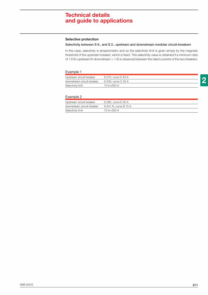
2/21ABB SACE
2
Selective protectionSelectivity between S 9.. and S 2.. upstream and downstream modular circuit-breakers
In this case, selectivity is amperometric and so the selectivity limit is given simply by the magneticthreshold of the upstream breaker, which is fixed. This selectivity value is obtained if a minimum ratioof 1.6 (In upstream/In downstream > 1.6) is observed between the rated currents of the two breakers.
Example 1Upstream circuit-breaker S 270, curve D 63 A
downstream circuit-breaker S 240, curve C 32 A
Selectivity limit 10 In=630 A
Example 2Upstream circuit-breaker S 280, curve D 50 A
downstream circuit-breaker S 941 N, curve B 10 A
Selectivity limit 10 In=500 A
Technical detailsand guide to applications

2/22 ABB SACE
2
Technical detailsand guide to applications
Upstream breaker S 290Im C C C
Icu [kA] 15 15 15
In [A] 80 100 125
Downstream C 4.5 2 T T T
breaker C 4.5 4 T T T
C 4.5 6 T T T
C 4.5 10 4 T T
S 931 N C 4.5 16 2.5 3.5 3.5
C 4.5 20 1.5 2.5 2.5
C 4.5 25 0.5 0.5 1.5
C 4.5 32 0.5 0.5 0.5
C 4.5 40 0.5 0.5 0.5
Upstream breaker S 290Im C C C
Icu [kA] 15 15 15
In [A] 80 100 125
Downstream B-C 6 2 T T T
breaker B-C 6 4 5 T T
B-C 6 6 4.5 5 T
B-C 6 10 4 4.5 5
S 941 N B-C 6 16 2.5 3.5 3.5
B-C 6 20 1.5 2.5 2.5
B-C 6 25 0.5 0.5 1.5
B-C 6 32 0.5 0.5 0.5
B-C 6 40 0.5 0.5 0.5
Upstream breaker S 290Im C C C
Icu [kA] 15 15 15
In [A] 80 100 125
Downstream B-C 10 2 6 8 9
breaker B-C 10 4 5 6 7.5
B-C 10 6 4.5 5 6
B-C 10 10 4 4.5 5
S 951 N B-C 10 16 2.5 3.5 3.5
B-C 10 20 1.5 2.5 2.5
B-C 10 25 0.5 0.5 1.5
B-C 10 32 0.5 0.5 0.5
B-C 10 40 0.5 0.5 0.5
Upstream breaker S 290Im C C C
Icu [kA] 15 15 15
In [A] 80 100 125
Downstream B-C 10 2 6 8 9
breaker B-C 10 4 5 6 7.5
B-C 10 6 4.5 5 6
B-C 10 10 4 4.5 5
S 971 N B-C 10 16 2.5 3.5 3.5
B-C 10 20 1.5 2.5 2.5
B-C 10 25 0.5 0.5 1.5
B-C 10 32 0.5 0.5 0.5
B-C 10 40 0.5 0.5 0.5
Upstream breaker: S 290Downstream breaker: modular

2/23ABB SACE
2
Technical detailsand guide to applications
Upstream breaker S 290Im D D
Icu [kA] 15 15
In [A] 80 100
Downstream C 4.5 2 T T
breaker C 4.5 4 T T
C 4.5 6 T T
C 4.5 10 T T
S 931 N C 4.5 16 4 T
C 4.5 20 3 T
C 4.5 25 2 4
C 4.5 32 1.5 3.5
C 4.5 40 1.5 3.5
Upstream breaker S 290Im D D
Icu [kA] 15 15
In [A] 80 100
Downstream B-C 6 2 T T
breaker B-C 6 4 T T
B-C 6 6 5.5 T
B-C 6 10 5 5
S 941 N B-C 6 16 4 4.5
B-C 6 20 3 4.5
B-C 6 25 2 4
B-C 6 32 1.5 3.5
B-C 6 40 1.5 3.5
Upstream breaker S 290Im D D
Icu [kA] 15 15
In [A] 80 100
Downstream B-C 10 2 7 8
breaker B-C 10 4 6 7
B-C 10 6 5.5 6
B-C 10 10 5 5
S 951 N B-C 10 16 4 4.5
B-C 10 20 3 4.5
B-C 10 25 2 4
B-C 10 32 1.5 3.5
B-C 10 40 1.5 3.5
Upstream breaker S 290Im D D
Icu [kA] 15 15
In [A] 80 100
Downstream B-C 10 2 7 8
breaker B-C 10 4 6 7
B-C 10 6 5.5 6
B-C 10 10 5 5
S 971 N B-C 10 16 4 4.5
B-C 10 20 3 4.5
B-C 10 25 2 4
B-C 10 32 1.5 3.5
B-C 10 40 1.5 3.5
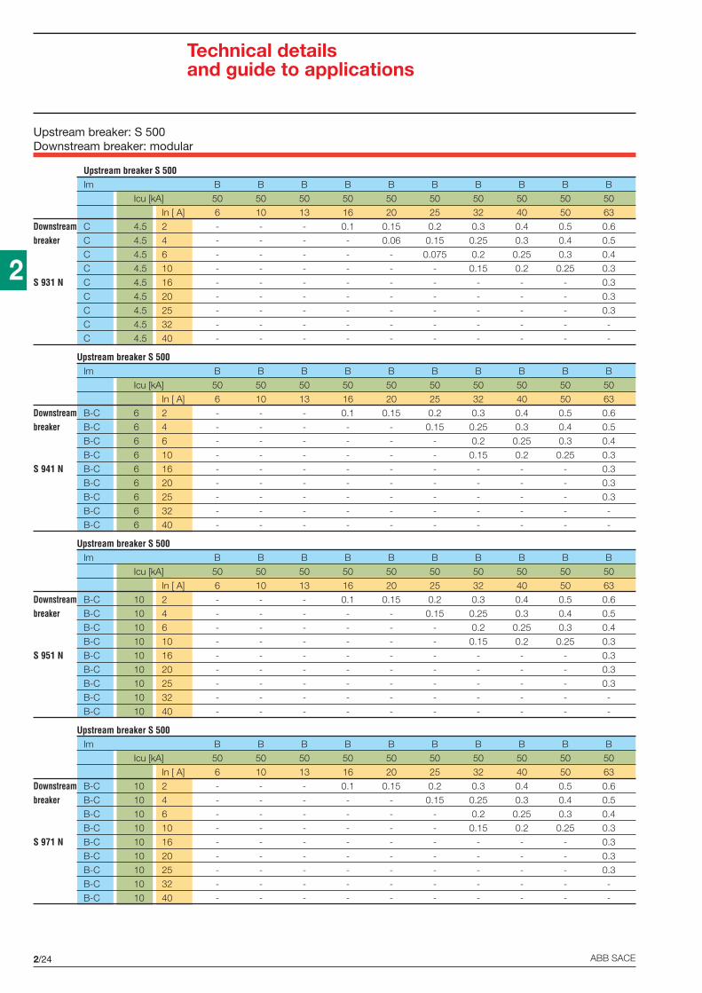
2/24 ABB SACE
2
Technical detailsand guide to applications
Upstream breaker S 500Im B B B B B B B B B B
Icu [kA] 50 50 50 50 50 50 50 50 50 50
In [ A] 6 10 13 16 20 25 32 40 50 63
Downstream C 4.5 2 - - - 0.1 0.15 0.2 0.3 0.4 0.5 0.6
breaker C 4.5 4 - - - - 0.06 0.15 0.25 0.3 0.4 0.5
C 4.5 6 - - - - - 0.075 0.2 0.25 0.3 0.4
C 4.5 10 - - - - - - 0.15 0.2 0.25 0.3
S 931 N C 4.5 16 - - - - - - - - - 0.3
C 4.5 20 - - - - - - - - - 0.3
C 4.5 25 - - - - - - - - - 0.3
C 4.5 32 - - - - - - - - - -
C 4.5 40 - - - - - - - - - -
Upstream breaker S 500Im B B B B B B B B B B
Icu [kA] 50 50 50 50 50 50 50 50 50 50
In [ A] 6 10 13 16 20 25 32 40 50 63
Downstream B-C 6 2 - - - 0.1 0.15 0.2 0.3 0.4 0.5 0.6
breaker B-C 6 4 - - - - - 0.15 0.25 0.3 0.4 0.5
B-C 6 6 - - - - - - 0.2 0.25 0.3 0.4
B-C 6 10 - - - - - - 0.15 0.2 0.25 0.3
S 941 N B-C 6 16 - - - - - - - - - 0.3
B-C 6 20 - - - - - - - - - 0.3
B-C 6 25 - - - - - - - - - 0.3
B-C 6 32 - - - - - - - - - -
B-C 6 40 - - - - - - - - - -
Upstream breaker S 500Im B B B B B B B B B B
Icu [kA] 50 50 50 50 50 50 50 50 50 50
In [ A] 6 10 13 16 20 25 32 40 50 63
Downstream B-C 10 2 - - - 0.1 0.15 0.2 0.3 0.4 0.5 0.6
breaker B-C 10 4 - - - - - 0.15 0.25 0.3 0.4 0.5
B-C 10 6 - - - - - - 0.2 0.25 0.3 0.4
B-C 10 10 - - - - - - 0.15 0.2 0.25 0.3
S 951 N B-C 10 16 - - - - - - - - - 0.3
B-C 10 20 - - - - - - - - - 0.3
B-C 10 25 - - - - - - - - - 0.3
B-C 10 32 - - - - - - - - - -
B-C 10 40 - - - - - - - - - -
Upstream breaker S 500Im B B B B B B B B B B
Icu [kA] 50 50 50 50 50 50 50 50 50 50
In [ A] 6 10 13 16 20 25 32 40 50 63
Downstream B-C 10 2 - - - 0.1 0.15 0.2 0.3 0.4 0.5 0.6
breaker B-C 10 4 - - - - - 0.15 0.25 0.3 0.4 0.5
B-C 10 6 - - - - - - 0.2 0.25 0.3 0.4
B-C 10 10 - - - - - - 0.15 0.2 0.25 0.3
S 971 N B-C 10 16 - - - - - - - - - 0.3
B-C 10 20 - - - - - - - - - 0.3
B-C 10 25 - - - - - - - - - 0.3
B-C 10 32 - - - - - - - - - -
B-C 10 40 - - - - - - - - - -
Upstream breaker: S 500Downstream breaker: modular
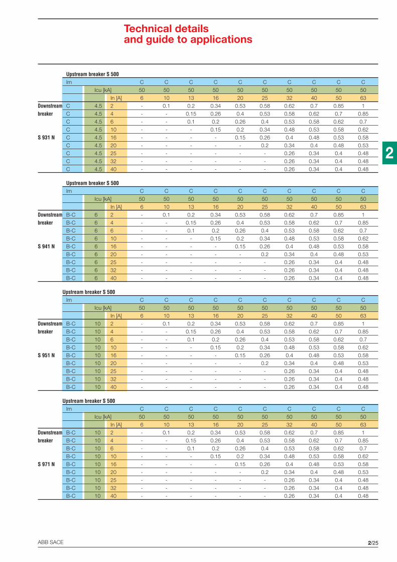
2/25ABB SACE
2
Technical detailsand guide to applications
Upstream breaker S 500Im C C C C C C C C C C
Icu [kA] 50 50 50 50 50 50 50 50 50 50
In [A] 6 10 13 16 20 25 32 40 50 63
Downstream C 4.5 2 - 0.1 0.2 0.34 0.53 0.58 0.62 0.7 0.85 1
breaker C 4.5 4 - - 0.15 0.26 0.4 0.53 0.58 0.62 0.7 0.85
C 4.5 6 - - 0.1 0.2 0.26 0.4 0.53 0.58 0.62 0.7
C 4.5 10 - - - 0.15 0.2 0.34 0.48 0.53 0.58 0.62
S 931 N C 4.5 16 - - - - 0.15 0.26 0.4 0.48 0.53 0.58
C 4.5 20 - - - - - 0.2 0.34 0.4 0.48 0.53
C 4.5 25 - - - - - - 0.26 0.34 0.4 0.48
C 4.5 32 - - - - - - 0.26 0.34 0.4 0.48
C 4.5 40 - - - - - - 0.26 0.34 0.4 0.48
Upstream breaker S 500Im C C C C C C C C C C
Icu [kA] 50 50 50 50 50 50 50 50 50 50
In [A] 6 10 13 16 20 25 32 40 50 63
Downstream B-C 6 2 - 0.1 0.2 0.34 0.53 0.58 0.62 0.7 0.85 1
breaker B-C 6 4 - - 0.15 0.26 0.4 0.53 0.58 0.62 0.7 0.85
B-C 6 6 - - 0.1 0.2 0.26 0.4 0.53 0.58 0.62 0.7
B-C 6 10 - - - 0.15 0.2 0.34 0.48 0.53 0.58 0.62
S 941 N B-C 6 16 - - - - 0.15 0.26 0.4 0.48 0.53 0.58
B-C 6 20 - - - - - 0.2 0.34 0.4 0.48 0.53
B-C 6 25 - - - - - - 0.26 0.34 0.4 0.48
B-C 6 32 - - - - - - 0.26 0.34 0.4 0.48
B-C 6 40 - - - - - - 0.26 0.34 0.4 0.48
Upstream breaker S 500Im C C C C C C C C C C
Icu [kA] 50 50 50 50 50 50 50 50 50 50
In [A] 6 10 13 16 20 25 32 40 50 63
Downstream B-C 10 2 - 0.1 0.2 0.34 0.53 0.58 0.62 0.7 0.85 1
breaker B-C 10 4 - - 0.15 0.26 0.4 0.53 0.58 0.62 0.7 0.85
B-C 10 6 - - 0.1 0.2 0.26 0.4 0.53 0.58 0.62 0.7
B-C 10 10 - - - 0.15 0.2 0.34 0.48 0.53 0.58 0.62
S 951 N B-C 10 16 - - - - 0.15 0.26 0.4 0.48 0.53 0.58
B-C 10 20 - - - - - 0.2 0.34 0.4 0.48 0.53
B-C 10 25 - - - - - - 0.26 0.34 0.4 0.48
B-C 10 32 - - - - - - 0.26 0.34 0.4 0.48
B-C 10 40 - - - - - - 0.26 0.34 0.4 0.48
Upstream breaker S 500Im C C C C C C C C C C
Icu [kA] 50 50 50 50 50 50 50 50 50 50
In [A] 6 10 13 16 20 25 32 40 50 63
Downstream B-C 10 2 - 0.1 0.2 0.34 0.53 0.58 0.62 0.7 0.85 1
breaker B-C 10 4 - - 0.15 0.26 0.4 0.53 0.58 0.62 0.7 0.85
B-C 10 6 - - 0.1 0.2 0.26 0.4 0.53 0.58 0.62 0.7
B-C 10 10 - - - 0.15 0.2 0.34 0.48 0.53 0.58 0.62
S 971 N B-C 10 16 - - - - 0.15 0.26 0.4 0.48 0.53 0.58
B-C 10 20 - - - - - 0.2 0.34 0.4 0.48 0.53
B-C 10 25 - - - - - - 0.26 0.34 0.4 0.48
B-C 10 32 - - - - - - 0.26 0.34 0.4 0.48
B-C 10 40 - - - - - - 0.26 0.34 0.4 0.48

2/26 ABB SACE
2
Technical detailsand guide to applications
Upstream breaker S 500Im D D D D D D D D D D
Icu [kA] 50 50 50 50 50 50 50 50 50 50
In [A] 6 10 13 16 20 25 32 40 50 63
Downstream C 4.5 2 - 0.24 0.5 1 2 3 T T T T
breaker C 4.5 4 - 0.2 0.32 0.5 1 2 3.5 T T T
C 4.5 6 - 0.15 0.24 0.35 0.5 1 2 4 T T
C 4.5 10 - - 0.2 0.32 0.35 0.5 0.5 2 T T
S 931 N C 4.5 16 - - - 0.24 0.3 0.5 0.5 1.5 3.5 T
C 4.5 20 - - - - - 0.35 0.5 1 2.5 3.5
C 4.5 25 - - - - - - 0.5 0.5 1.5 2
C 4.5 32 - - - - - - - - 0.51 1.5
C 4.5 40 - - - - - - - - - 0.51
Upstream breaker S 500Im D D D D D D D D D D
Icu [kA] 50 50 50 50 50 50 50 50 50 50
In [A] 6 10 13 16 20 25 32 40 50 63
Downstream B-C 6 2 - 0.24 0.5 1 2 3 T T T T
breaker B-C 6 4 - 0.2 0.32 0.5 1 2 3.5 T T T
B-C 6 6 - 0.15 0.24 0.35 0.5 1 2 4 T T
B-C 6 10 - - 0.2 0.32 0.35 0.5 0.5 2 T T
S 941 N B-C 6 16 - - - 0.24 0.3 0.5 0.5 1.5 3.5 T
B-C 6 20 - - - - - 0.35 0.5 1 2.5 3.5
B-C 6 25 - - - - - - 0.5 0.5 1.5 2
B-C 6 32 - - - - - - - - 0.51 1.5
B-C 6 40 - - - - - - - - - 0.51
Upstream breaker S 500Im D D D D D D D D D D
Icu [kA] 50 50 50 50 50 50 50 50 50 50
In [A] 6 10 13 16 20 25 32 40 50 63
Downstream B-C 10 2 - 0.24 0.5 1 2 3 T T T T
breaker B-C 10 4 - 0.2 0.32 0.5 1 2 3.5 T T T
B-C 10 6 - 0.15 0.24 0.35 0.5 1 2 4 T T
B-C 10 10 - - 0.2 0.32 0.35 0.5 0.5 2 T T
S 951 N B-C 10 16 - - - 0.24 0.3 0.5 0.5 1.5 3.5 T
B-C 10 20 - - - - - 0.35 0.5 1 2.5 3.5
B-C 10 25 - - - - - - 0.5 0.5 1.5 2
B-C 10 32 - - - - - - - - 0.51 1.5
B-C 10 40 - - - - - - - - - 0.51
Upstream breaker S 500Im D D D D D D D D D D
Icu [kA] 50 50 50 50 50 50 50 50 50 50
In [A] 6 10 13 16 20 25 32 40 50 63
Downstream B-C 10 2 - 0.24 0.5 1 2 3 T T T T
breaker B-C 10 4 - 0.2 0.32 0.5 1 2 3.5 T T T
B-C 10 6 - 0.15 0.24 0.35 0.5 1 2 4 T T
B-C 10 10 - - 0.2 0.32 0.35 0.5 0.5 2 T T
S 971 N B-C 10 16 - - - 0.24 0.3 0.5 0.5 1.5 3.5 T
B-C 10 20 - - - - - 0.35 0.5 1 2.5 3.5
B-C 10 25 - - - - - - 0.5 0.5 1.5 2
B-C 10 32 - - - - - - - - 0.51 1.5
B-C 10 40 - - - - - - - - - 0.51

2/27ABB SACE
2
Technical detailsand guide to applications
Upstream breaker S 700Im E E E E E E E E
Icu [kA] 30 30 30 30 30 30 30 30
In [A] 20 25 32 40 50 63 80 100
Downstream C 4.5 2 T T T T T T T T
breaker C 4.5 4 T T T T T T T T
C 4.5 6 T T T T T T T T
C 4.5 10 T T T T T T T T
S 931 N C 4.5 16 - T T T T T T T
C 4.5 20 - - T T T T T T
C 4.5 25 - - T T T T T T
C 4.5 32 - - - - T T T T
C 4.5 40 - - - - - T T T
Upstream breaker S 700Im E E E E E E E E
Icu [kA] 30 30 30 30 30 30 30 30
In [A] 20 25 32 40 50 63 80 100
Downstream B-C 6 2 T T T T T T T T
breaker B-C 6 4 T T T T T T T T
B-C 6 6 T T T T T T T T
B-C 6 10 T T T T T T T T
S 941 N B-C 6 16 - T T T T T T T
B-C 6 20 - - T T T T T T
B-C 6 25 - - T T T T T T
B-C 6 32 - - - - T T T T
B-C 6 40 - - - - - T T T
Upstream breaker S 700Im E E E E E E E E
Icu [kA] 30 30 30 30 30 30 30 30
In [A] 20 25 32 40 50 63 80 100
Downstream B-C 10 2 T T T T T T T T
breaker B-C 10 4 T T T T T T T T
B-C 10 6 T T T T T T T T
B-C 10 10 T T T T T T T T
S 951 N B-C 10 16 - T T T T T T T
B-C 10 20 - - T T T T T T
B-C 10 25 - - T T T T T T
B-C 10 32 - - - - T T T T
B-C 10 40 - - - - - T T T
Upstream breaker S 700Im E E E E E E E E
Icu [kA] 30 30 30 30 30 30 30 30
In [A] 20 25 32 40 50 63 80 100
Downstream B-C 10 2 T T T T T T T T
breaker B-C 10 4 T T T T T T T T
B-C 10 6 T T T T T T T T
B-C 10 10 T T T T T T T T
S 971 N B-C 10 16 - T T T T T T T
B-C 10 20 - - T T T T T T
B-C 10 25 - - T T T T T T
B-C 10 32 - - - - T T T T
B-C 10 40 - - - - - T T T
Upstream breaker: S 700Downstream breaker: modular

2/28 ABB SACE
2
Technical detailsand guide to applications
Upstream fuse gI, gGIm Icu [kA] 100 100 100 100 100 100 120 120
In [A] 25 32 40 50 63 80 100 125
Downstream C 4.5 2 1.5 2.5 T T T T T T
breaker C 4.5 4 1 2 T T T T T T
C 4.5 6 1 1.5 4 T T T T T
C 4.5 10 - 1.2 3.5 4 T T T T
S 931 N C 4.5 16 - 1 3 3.5 T T T T
C 4.5 20 - 1 3 3.5 T T T T
C 4.5 25 - 1 2 3 T T T T
C 4.5 32 - 1 2 3 T T T T
C 4.5 40 - - 1.5 2.5 4 T T T
Upstream fuse gI, gGIm Icu [kA] 100 100 100 100 100 100 120 120
In [A] 25 32 40 50 63 80 100 125
Downstream B-C 6 2 1.5 2.5 T T T T T T
breaker B-C 6 4 1 2 T T T T T T
B-C 6 6 1 1.5 4 T T T T T
B-C 6 10 - 1.2 3.5 4 T T T T
S 941 N B-C 6 16 - 1 3 3.5 T T T T
B-C 6 20 - 1 3 3.5 T T T T
B-C 6 25 - 1 2 3 T T T T
B-C 6 32 - 1 2 3 T T T T
B-C 6 40 - - 1.5 2.5 4 T T T
Upstream fuse gI, gGIm Icu [kA] 100 100 100 100 100 100 120 120
In [A] 25 32 40 50 63 80 100 125
Downstream B-C 10 2 1.5 2.5 T T T T T T
breaker B-C 10 4 1 2 T T T T T T
B-C 10 6 1 1.5 4 T T T T T
B-C 10 10 - 1.2 3.5 4 T T T T
S 951 N B-C 10 16 - 1 3 3.5 T T T T
B-C 10 20 - 1 3 3.5 T T T T
B-C 10 25 - 1 2 3 T T T T
B-C 10 32 - 1 2 3 T T T T
B-C 10 40 - - 1.5 2.5 4 T T T
Upstream fuse gI, gGIm Icu [kA] 100 100 100 100 100 100 120 120
In [A] 25 32 40 50 63 80 100 125
Downstream B-C 10 2 1.5 2.5 T T T T T T
breaker B-C 10 4 1 2 T T T T T T
B-C 10 6 1 1.5 4 T T T T T
B-C 10 10 - 1.2 3.5 4 T T T T
S 971 N B-C 10 16 - 1 3 3.5 T T T T
B-C 10 20 - 1 3 3.5 T T T T
B-C 10 25 - 1 2 3 T T T T
B-C 10 32 - 1 2 3 T T T T
B-C 10 40 - - 1.5 2.5 4 T T T
Upstream: fuseDownstream breaker: modular

2/29ABB SACE
2
Technical detailsand guide to applications
S 290 D - S 250 B-CS 290 D - S 240 C400 V Upstream breaker S 290
Icu [kA] 15
Downstream In [A] 80 100
breaker Char. D D
6 C T T
8 C T T
10 C 5 T
13 C 4.5 7
S 240 7.5 16 C 4.5 7
20 C 3.5 5
25 C 3.5 5
32 C 4.5
40 C
400 V Upstream breaker S 290Icu [kA] 15
Downstream In [A] 80 100
breaker Char. D D
≤2 C T T
3 C T T
4 C T T
6 B-C T T
8 B-C T T
10 B-C 5 8
S 250 1013 B-C 4.5 7
16 B-C 4.5 7
20 B-C 3.5 5
25 B-C 3.5 5
32 B-C 4.5
40 B-C
50 B-C
63 B-C
S 290 D - S 250 K
400 V Upstream breaker S 290Icu [kA] 15
Downstream In [A] 80 100
breaker Char. D D
≤2 K T T
3 K T T
4 K T T
6 K T T
8 K T T
10 K 5 8
S 250 10 16 K 3 5
20 K 3 7
25 K 4
32 K
40 K
50 K
63 K
Upstream breaker: modularDownstream breaker: modular
S 290 D - S 260 B-C
400 V Upstream breaker S 290Icu [kA] 15
Downstream In [A] 80 100
breaker Char. D D
≤2 C T T
3 C T T
4 C T T
6 B-C T T
8 B-C T T
10 B-C 5 8
S 260 1013 B-C 4.5 7
16 B-C 4.5 7
20 B-C 3.5 5
25 B-C 3.5 5
32 B-C 4.5
40 B-C
50 B-C
63 B-C
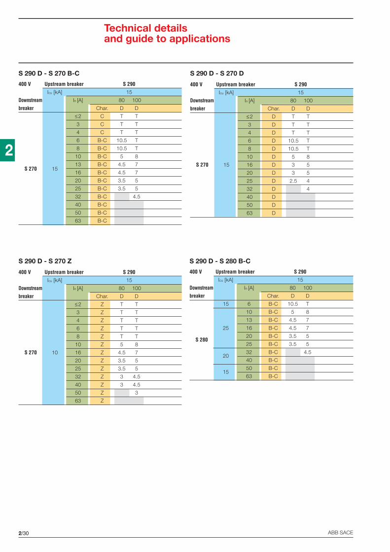
2/30 ABB SACE
2
S 290 D - S 270 B-C S 290 D - S 270 D
400 V Upstream breaker S 290Icu [kA] 15
Downstream In [A] 80 100
breaker Char. D D
≤2 C T T
3 C T T
4 C T T
6 B-C 10.5 T
8 B-C 10.5 T
10 B-C 5 8
13 B-C 4.5 7S 270 15
16 B-C 4.5 7
20 B-C 3.5 5
25 B-C 3.5 5
32 B-C 4.5
40 B-C
50 B-C
63 B-C
S 290 D - S 270 Z S 290 D - S 280 B-C
400 V Upstream breaker S 290Icu [kA] 15
Downstream In [A] 80 100
breaker Char. D D
≤2 D T T
3 D T T
4 D T T
6 D 10.5 T
8 D 10.5 T
10 D 5 8
S 270 15 16 D 3 5
20 D 3 5
25 D 2.5 4
32 D 4
40 D
50 D
63 D
400 V Upstream breaker S 290Icu [kA] 15
Downstream In [A] 80 100
breaker Char. D D
≤2 Z T T
3 Z T T
4 Z T T
6 Z T T
8 Z T T
10 Z 5 8
S 270 10 16 Z 4.5 7
20 Z 3.5 5
25 Z 3.5 5
32 Z 3 4.5
40 Z 3 4.5
50 Z 3
63 Z
400 V Upstream breaker S 290Icu [kA] 15
Downstream In [A] 80 100
breaker Char. D D
15 6 B-C 10.5 T
10 B-C 5 8
13 B-C 4.5 7
25 16 B-C 4.5 7
S 28020 B-C 3.5 5
25 B-C 3.5 5
2032 B-C 4.5
40 B-C
1550 B-C
63 B-C
Technical detailsand guide to applications
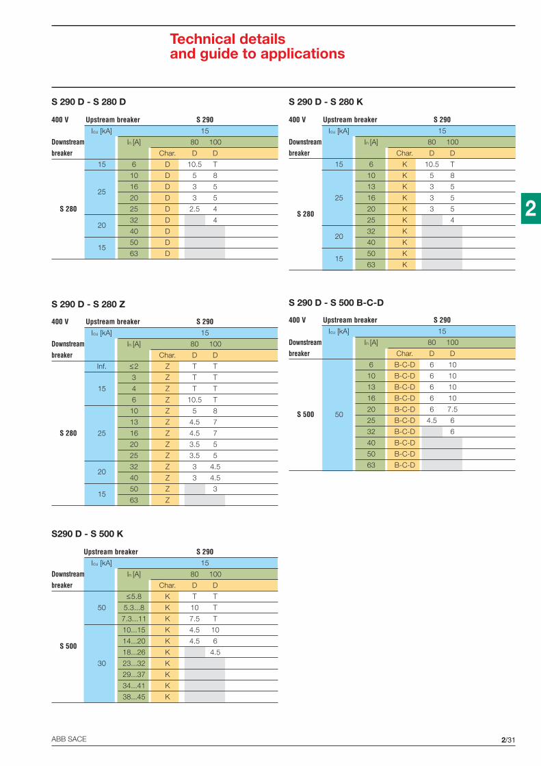
2/31ABB SACE
2
S 290 D - S 280 D S 290 D - S 280 K
S 290 D - S 280 Z S 290 D - S 500 B-C-D
S290 D - S 500 K
Upstream breaker S 290Icu [kA] 15
Downstream In [A] 80 100
breaker Char. D D
≤5.8 K T T
50 5.3...8 K 10 T
7.3...11 K 7.5 T
10...15 K 4.5 10
S 50014...20 K 4.5 6
18...26 K 4.5
30 23...32 K
29...37 K
34...41 K
38...45 K
400 V Upstream breaker S 290Icu [kA] 15
Downstream In [A] 80 100
breaker Char. D D
Inf. ≤2 Z T T
3 Z T T
15 4 Z T T
6 Z 10.5 T
10 Z 5 8
13 Z 4.5 7
S 280 25 16 Z 4.5 7
20 Z 3.5 5
25 Z 3.5 5
2032 Z 3 4.5
40 Z 3 4.5
1550 Z 3
63 Z
400 V Upstream breaker S 290Icu [kA] 15
Downstream In [A] 80 100
breaker Char. D D
15 6 D 10.5 T
10 D 5 8
2516 D 3 5
20 D 3 5
S 280 25 D 2.5 4
2032 D 4
40 D
1550 D
63 D
400 V Upstream breaker S 290Icu [kA] 15
Downstream In [A] 80 100
breaker Char. D D
15 6 K 10.5 T
10 K 5 8
13 K 3 5
25 16 K 3 5
S 28020 K 3 5
25 K 4
2032 K
40 K
1550 K
63 K
400 V Upstream breaker S 290Icu [kA] 15
Downstream In [A] 80 100
breaker Char. D D
6 B-C-D 6 10
10 B-C-D 6 10
13 B-C-D 6 10
16 B-C-D 6 10
S 500 5020 B-C-D 6 7.5
25 B-C-D 4.5 6
32 B-C-D 6
40 B-C-D
50 B-C-D
63 B-C-D
Technical detailsand guide to applications

2/32 ABB SACE
2
S 500 D - S 240 C S 500 D - S 250 B-C
S 500 D - S 250 K
400 V Upstream breaker S 500Icu [kA] 50
Downstream In[A] 32 40 50 63
breaker Char. D D D D
≤2 C T T T T
3 C 3 6 T T
4 C 2 3 6 T
6 B-C 1.5 2 3 5.5
8 B-C 1.5 2 3 5.5
10 B-C 1 1.5 2 3
13 B-C 1.5 2 3S 250 10
16 B-C 2 3
20 B-C 2.5
25 B-C
32 B-C
40 B-C
50 B-C
63 B-C
400 V Upstream breaker S 500Icu [kA] 50
Downstream In[A] 32 40 50 63
breaker Char. D D D D
6 C 1.5 2 3 5.5
8 C 1.5 2 3 5.5
10 C 1 1.5 2 3
13 C 1.5 2 3
S 240 7.5 16 C 2 3
20 C 2.5
25 C
32 C
40 C
400 V Upstream breaker S 500Icu [kA] 50
Downstream In [A] 32 40 50 63
breaker Char. D D D D
≤2 K T T T T
3 K 3 6 T T
4 K 2 3 6 T
6 K 1.5 2 3 5.5
8 K 1.5 2 3 5.5
10 K 1.5 2 3
S 250 10 16 K 2
20 K
25 K
32 K
40 K
50 K
63 K
Technical detailsand guide to applications
S 500 D - S 260 B-C
400 V Upstream breaker S 500Icu [kA] 50
Downstream In[A] 32 40 50 63
breaker Char. D D D D
≤2 C T T T T
3 C 3 6 T T
4 C 2 3 6 T
6 B-C 1.5 2 3 5.5
8 B-C 1.5 2 3 5.5
10 B-C 1 1.5 2 3
13 B-C 1.5 2 3S 260 10
16 B-C 2 3
20 B-C 2.5
25 B-C
32 B-C
40 B-C
50 B-C
63 B-C

2/33ABB SACE
2
S 500 D - S 270 B-C S 500 D - S 270 D
S 500 D - S 280 B-CS 500 D - S 270 Z
400 V Upstream breaker S 500Icu [kA] 50
Downstream In [A] 32 40 50 63
breaker Char. D D D D
≤2 C T T T T
3 C 3 6 T T
4 C 2 3 6 T
6 B-C 1.5 2 3 5.5
8 B-C 1.5 2 3 5.5
10 B-C 1 1.5 2 3
S 270 1513 B-C 1.5 2 3
16 B-C 2 3
20 B-C 2.5
25 B-C
32 B-C
40 B-C
50 B-C
63 B-C
400 V Upstream breaker S 500Icu [kA] 50
Downstream In [A] 32 40 50 63
breaker Char. D D D D
≤2 D T T T T
3 D 3 6 T T
4 D 2 3 6 T
6 D 1.5 2 3 5.5
8 D 1.5 2 3 5.5
10 D 1 1.5 2 3
S 270 15 16 D 1.5 2
20 D 2
25 D
32 D
40 D
50 D
63 D
400 V Upstream breaker S 500Icu [kA] 50
Downstream In [A] 32 40 50 63
breaker Char. D D D D
≤2 Z T T T T
3 Z 3 6 T T
4 Z 2 3 6 T
6 Z 1.5 2 3 5.5
8 Z 1.5 2 3 5.5
10 Z 1 1.5 2 3
S 270 10 16 Z 1 1.5 2 3
20 Z 1.5 2 2.5
25 Z 2 2.5
32 Z 2
40 Z
50 Z
63 Z
400 V Upstream breaker S 500Icu [kA] 50
Downstream In [A] 32 40 50 63
breaker Char. D D D D
15 6 B-C 1.5 2 3 5
10 B-C 1 1.5 2 3
13 B-C 1.5 2 3
25 16 B-C 2 3
S 28020 B-C 2.5
25 B-C
2032 B-C
40 B-C
1550 B-C
63 B-C
Technical detailsand guide to applications

2/34 ABB SACE
2
S 500 D - S 280 D S 500 D - S 280 K
S 500 D - S 280 Z
400 V Upstream breaker S 500Icu [kA] 50
Downstream In [A] 32 40 50 63
breaker Char. D D D D
15 6 D 1.5 2 3 5
10 D 1 1.5 2 3
2516 D 1.5 2
20 D 2
S 280 25 D
2032 D
40 D
1550 D
63 D
400 V Upstream breaker S 500Icu [kA] 50
Downstream In [A] 32 40 50 63
breaker Char. D D D D
15 6 K 1.5 2 3 5
10 K 1.5 2 3
13 K 1.5 2
25 16 K 2
S 28020 K
25 K
2032 K
40 K
1550 K
63 K
400 V Upstream breaker S 500Icu [kA] 50
Downstream In [A] 32 40 50 63
breaker Char. D D D D
Inf. ≤2 Z T T T T
3 Z 3 6 T T
15 4 Z 2 3 6 T
6 Z 1.5 2 3 5.5
10 Z 1 1.5 2 3
13 Z 1 1.5 2 3
S 280 25 16 Z 1 1.5 2 3
20 Z 1.5 2 2.5
25 Z 2 2.5
2032 Z 2
40 Z
1550 Z
63 Z
Technical detailsand guide to applications
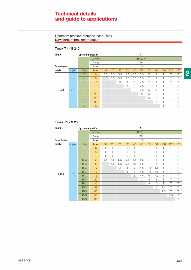
2/35ABB SACE
2
Tmax T1 - S 240
Tmax T1 - S 250
400 V Upstream breaker T1Version B, C, N
Relay TM
Downstream Iu [A] 160
breaker Icu [kA] Char. In [A] 16 20 25 32 40 50 63 80 100 125 160
C 6 5.5 5.5 5.5 5.5 5.5 5.5 T T T T T
C 8 5.5 5.5 5.5 5.5 5.5 T T T T T
C 10 3 3 3 4.5 T T T T T
C 13 3 3 4.5 T T T T T
S 240 7.5 C 16 3 4.5 5 T T T T
C 20 3 5 6 T T T
C 25 5 6 T T T
C 32 6 T T T
C 40 T T T
400 V Upstream breaker T1Version B, C, N
Relay TM
Downstream Iu [A] 160
breaker Icu [kA] Char. In [A] 16 20 25 32 40 50 63 80 100 125 160
C ≤2 T T T T T T T T T T T
C 3 T T T T T T T T T T T
C 4 T T T T T T T T T T T
B-C 6 5.5 5.5 5.5 5.5 5.5 5.5 T T T T T
B-C 8 5.5 5.5 5.5 5.5 5.5 T T T T T
B-C 10 3 3 3 4.5 7.5 8.5 T T T
S 250 10B-C 13 3 3 4.5 7.5 7.5 T T T
B-C 16 3 4.5 5 7.5 T T T
B-C 20 3 5 6 T T T
B-C 25 5 6 T T T
B-C 32 6 7.5 T T
B-C 40 7.5 T T
B-C 50 7.5 T
B-C 63 T
Upstream breaker: moulded-case TmaxDownstream breaker: modular
Technical detailsand guide to applications

2/36 ABB SACE
2
Tmax T1 - S 250
Tmax T1 - S 260
400 V Upstream breaker T1Version B, C, N
Relay TM
Downstream Iu [A] 160
breaker Icu [kA] Char. In [A] 16 20 25 32 40 50 63 80 100 125 160
K ≤2 T T T T T T T T T T T
K 3 T T T T T T T T T T T
K 4 T T T T T T T T T T T
K 6 5.5 5.5 5.5 5.5 5.5 5.5 T T T T T
K 8 5.5 5.5 5.5 5.5 5.5 T T T T T
K 10 3 3 3 3 6 8.5 T T T
S 250 10 K 16 3 3 4.5 7.5 T T T
K 20 3 3.5 5.5 6.5 T T
K 25 3.5 5.5 6 9.5 T
K 32 4.5 6 9.5 T
K 40 5 8 T
K 50 6 9.5
K 63 9.5
400 V Upstream breaker T1Version B, C, N
Relay TM
Downstream Iu [A] 160
breaker Icu [kA] Char. In [A] 16 20 25 32 40 50 63 80 100 125 160
C ≤2 T T T T T T T T T T T
C 3 T T T T T T T T T T T
C 4 T T T T T T T T T T T
B-C 6 5.5 5.5 5.5 5.5 5.5 5.5 T T T T T
B-C 8 5.5 5.5 5.5 5.5 5.5 T T T T T
B-C 10 3 3 3 4.5 7.5 8.5 T T T
S 260 10B-C 13 3 3 4.5 7.5 7.5 T T T
B-C 16 3 4.5 5 7.5 T T T
B-C 20 3 5 6 T T T
B-C 25 5 6 T T T
B-C 32 6 7.5 T T
B-C 40 7.5 T T
B-C 50 7.5 T
B-C 63 T
Technical detailsand guide to applications
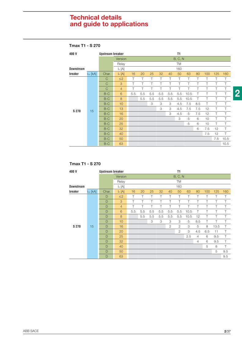
2/37ABB SACE
2
Tmax T1 - S 270
Tmax T1 - S 270
400 V Upstream breaker T1Version B, C, N
Relay TM
Downstream Iu [A] 160
breaker Icu [kA] Char. In [A] 16 20 25 32 40 50 63 80 100 125 160
C ≤2 T T T T T T T T T T T
C 3 T T T T T T T T T T T
C 4 T T T T T T T T T T T
B-C 6 5.5 5.5 5.5 5.5 5.5 5.5 10.5 T T T T
B-C 8 5.5 5.5 5.5 5.5 5.5 10.5 T T T T
B-C 10 3 3 3 4.5 7.5 8.5 T T T
S 270 15B-C 13 3 3 4.5 7.5 7.5 12 T T
B-C 16 3 4.5 5 7.5 12 T T
B-C 20 3 5 6 10 T T
B-C 25 5 6 10 T T
B-C 32 6 7.5 12 T
B-C 40 7.5 12 T
B-C 50 7.5 10.5
B-C 63 10.5
400 V Upstream breaker T1Version B, C, N
Relay TM
Downstream Iu [A] 160
breaker Icu [kA] Char. In [A] 16 20 25 32 40 50 63 80 100 125 160
D ≤2 T T T T T T T T T T T
D 3 T T T T T T T T T T T
D 4 T T T T T T T T T T T
D 6 5.5 5.5 5.5 5.5 5.5 5.5 10.5 T T T T
D 8 5.5 5.5 5.5 5.5 5.5 10.5 12 T T T
D 10 3 3 3 3 5 8.5 T T T
S 270 15 D 16 2 2 3 5 8 13.5 T
D 20 2 3 4.5 6.5 11 T
D 25 2.5 4 6 9.5 T
D 32 4 6 9.5 T
D 40 5 8 T
D 50 5 9.5
D 63 9.5
Technical detailsand guide to applications

2/38 ABB SACE
2
Tmax T1 - S 270
Tmax T1 - S 280
400 V Upstream breaker T1Version B, C, N
Relay TM
Downstream Iu [A] 160
breaker Icu [kA] Char. In [A] 16 20 25 32 40 50 63 80 100 125 160
Z ≤2 T T T T T T T T T T T
Z 3 T T T T T T T T T T T
Z 4 T T T T T T T T T T T
Z 6 5.5 5.5 5.5 5.5 5.5 5.5 T T T T T
Z 8 5.5 5.5 5.5 5.5 5.5 T T T T T
Z 10 3 3 3 4.5 8 8.5 T T T
S 270 10 Z 16 3 4.5 5 7.5 T T T
Z 20 3 5 6 T T T
Z 25 5 6 T T T
Z 32 6 7.5 T T
Z 40 7.5 T T
Z 50 7.5 T
Z 63 T
400 V Upstream breaker T1Version B, C, N
Relay TM
Downstream Iu [A] 160
breaker Icu [kA] Char. In [A] 16 20 25 32 40 50 63 80 100 125 160
15 B-C 6 5.5 5.5 5.5 5.5 5.5 5.5 10.5 T T T T
B-C 10 3 3 3 4.5 7.5 8.5 17* T T
B-C 13 3 3 4.5 7.5 7.5 12 20* T
25 B-C 16 3 4.5 5 7.5 12 20* T
S 280B-C 20 3 5 6 10 15 T
B-C 25 5 6 10 15 T
20B-C 32 6 7.5 12 T
B-C 40 7.5 12 T
15B-C 50 7.5 10.5
B-C 63 10.5
* Consider the lower value between the breaking capacity of the upstream circuit-breaker and the valueindicated.
Technical detailsand guide to applications

2/39ABB SACE
2
Tmax T1 - S 280
Tmax T1 - S 280
400 V Upstream breaker T1Version B, C, N
Relay TM
Downstream Iu [A] 160
breaker Icu [kA] Char. In [A] 16 20 25 32 40 50 63 80 100 125 160
15 D 6 5.5 5.5 5.5 5.5 5.5 5.5 10.5 T T T T
D 10 3 3 3 3 5 8.5 17* T T
25D 16 2 2 3 5 8 13.5 T
D 20 2 3 4.5 6.5 11 T
S 280 D 25 2.5 4 6 9.5 T
20D 32 4 6 9.5 T
D 40 5 8 T
15D 50 5 9.5
D 63 9.5
400 V Upstream breaker T1Version B, C, N
Relay TM
Downstream Iu [A] 160
breaker Icu [kA] Char. In [A] 16 20 25 32 40 50 63 80 100 125 160
15 K 6 5.5 5.5 5.5 5.5 5.5 5.5 10.5 T T T T
K 10 3 3 3 3 6 8.5 17* T T
K 13 3 3 5 7.5 10 13.5 T
25 K 16 3 3 4.5 7.5 10 13.5 T
S 280K 20 3 3.5 5.5 6.5 11 T
K 25 3.5 5.5 6 9.5 T
20K 32 4.5 6 9.5 T
K 40 5 8 T
15K 50 6 9.5
K 63 9.5
* Consider the lower value between the breaking capacity of the upstream circuit-breaker and the valueindicated.
Technical detailsand guide to applications
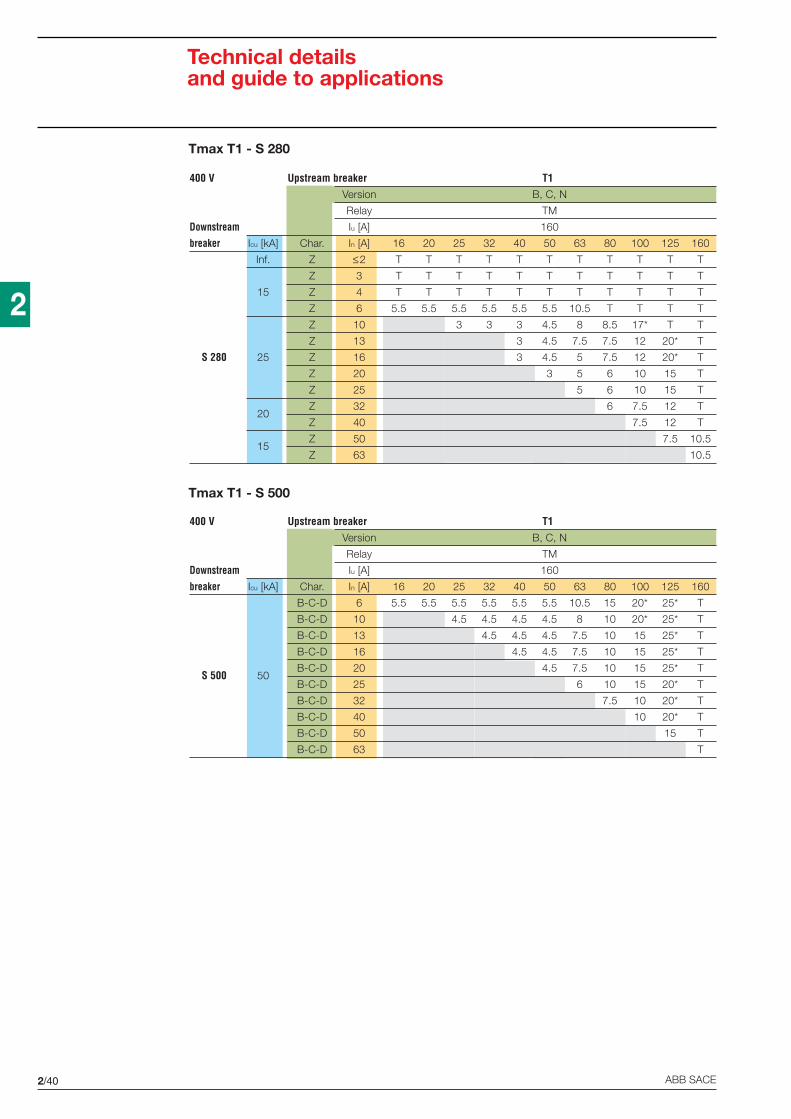
2/40 ABB SACE
2
Tmax T1 - S 280
Tmax T1 - S 500
400 V Upstream breaker T1Version B, C, N
Relay TM
Downstream Iu [A] 160
breaker Icu [kA] Char. In [A] 16 20 25 32 40 50 63 80 100 125 160
Inf. Z ≤2 T T T T T T T T T T T
Z 3 T T T T T T T T T T T
15 Z 4 T T T T T T T T T T T
Z 6 5.5 5.5 5.5 5.5 5.5 5.5 10.5 T T T T
Z 10 3 3 3 4.5 8 8.5 17* T T
Z 13 3 4.5 7.5 7.5 12 20* T
S 280 25 Z 16 3 4.5 5 7.5 12 20* T
Z 20 3 5 6 10 15 T
Z 25 5 6 10 15 T
20Z 32 6 7.5 12 T
Z 40 7.5 12 T
15Z 50 7.5 10.5
Z 63 10.5
400 V Upstream breaker T1Version B, C, N
Relay TM
Downstream Iu [A] 160
breaker Icu [kA] Char. In [A] 16 20 25 32 40 50 63 80 100 125 160
B-C-D 6 5.5 5.5 5.5 5.5 5.5 5.5 10.5 15 20* 25* T
B-C-D 10 4.5 4.5 4.5 4.5 8 10 20* 25* T
B-C-D 13 4.5 4.5 4.5 7.5 10 15 25* T
B-C-D 16 4.5 4.5 7.5 10 15 25* T
S 500 50B-C-D 20 4.5 7.5 10 15 25* T
B-C-D 25 6 10 15 20* T
B-C-D 32 7.5 10 20* T
B-C-D 40 10 20* T
B-C-D 50 15 T
B-C-D 63 T
Technical detailsand guide to applications

2/41ABB SACE
2
Tmax T1 - S 500
400 V Upstream breaker T1Version B, C, N
Relay TM
Downstream Iu [A] 160
breaker Icu [kA] Char. In [A] 16 20 25 32 40 50 63 80 100 125 160
K ≤5.8 36 36 T T T T T T T T T
50 K 5.3...8 5.5 5.5 5.5 5.5 5.5 5.5 10.5 T T T T
K 7.3...11 4.5 4.5 4.5 4.5 8 T T T T
K 10...15 4.5 4.5 4.5 7.5 10 15 T T
S 500K 14...20 4.5 4.5 7.5 10 15 T T
K 18...26 4.5 7.5 10 15 T T
30 K 23...32 6 10 15 20* T
K 29...37 7.5 10 20* T
K 34...41 10 20* T
K 38...45 15 T
* Consider the lower value between the breaking capacity of the upstream circuit-breaker and the valueindicated.
Technical detailsand guide to applications

2/42 ABB SACE
2
Tmax T2 - S 240
400 V Upstream breaker T2Version N, S, H, L
Relay TM, M EL
Downstream Iu [A] 160
breaker Icu [kA] Char. In [A] 12.5 16 20 25 32 40 50 63 80 100 125 160 10 25 63 100 160
C 6 5.5* 5.5 5.5 5.5 5.5 5.5 5.5 T T T T T T T T T
C 8 5.5 5.5 5.5 5.5 5.5 T T T T T T T T T
C 10 3* 3 3 3 4.5 T T T T T T T T T
C 13 3* 3 3 4.5 T T T T T T T T T
S 240 7.5 C 16 3* 3 4.5 5 T T T T T T T
C 20 3* 3 5 6 T T T T T T
C 25 3* 5 6 T T T T T T
C 32 3* 6 T T T T T T
C 40 5.5* T T T T T
* Value valid with magnetic only breaker upstream.
Tmax T2 - S 250
400 V Upstream breaker T2Version N, S, H, L
Relay TM, M EL
Downstream Iu [A] 160
breaker Icu [kA] Char. In [A] 12.5 16 20 25 32 40 50 63 80 100 125 160 10 25 63 100 160
C ≤2 T T T T T T T T T T T T T T T T T
C 3 T T T T T T T T T T T T T T T T T
C 4 T T T T T T T T T T T T T T T T T
B-C 6 5.5* 5.5 5.5 5.5 5.5 5.5 5.5 T T T T T T T T T
B-C 8 5.5 5.5 5.5 5.5 5.5 T T T T T T T T T
B-C 10 3* 3 3 3 4.5 7.5 8.5 T T T T T T T
S 250 10B-C 13 3* 3 3 4.5 7.5 7.5 T T T T T T T
B-C 16 3* 3 4.5 5 7.5 T T T T T T
B-C 20 3* 3 5 6 T T T T T T
B-C 25 3* 5 6 T T T T T T
B-C 32 3* 6 7.5 T T T T T
B-C 40 5.5* 7.5 T T T T
B-C 50 3* 5* 7.5 T T T
B-C 63 5* T T
* Value valid with magnetic only breaker upstream.
Technical detailsand guide to applications

2/43ABB SACE
2
Tmax T2 - S 250
Tmax T2 - S 260
400 V Upstream breaker T2Version N, S, H, L
Relay TM, M EL
Downstream Iu [A] 160
breaker Icu [kA] Char. In [A] 12.5 16 20 25 32 40 50 63 80 100 125 160 10 25 63 100 160
K ≤2 T T T T T T T T T T T T T T T T T
K 3 T T T T T T T T T T T T T T T T T
K 4 T T T T T T T T T T T T T T T T T
K 6 5.5* 5.5 5.5 5.5 5.5 5.5 5.5 T T T T T T T T T
K 8 5.5 5.5 5.5 5.5 5.5 T T T T T T T T T
K 10 3* 3 3 3 3 6 8.5 T T T T T T T
S 250 10 K 16 2* 3 3 4.5 7.5 T T T T T T
K 20 2* 3 3.5 5.5 6.5 T T T T T
K 25 2* 3.5 5.5 6 9.5 T T T T
K 32 4.5 6 9.5 T T T T
K 40 3* 5 8 T T T
K 50 2* 3* 6 9.5 9.5 9.5
K 63 3* 9.5 9.5
* Value valid with magnetic only breaker upstream.
400 V Upstream breaker T2Version N, S, H, L
Relay TM, M EL
Downstream Iu [A] 160
breaker Icu [kA] Char. In [A] 12.5 16 20 25 32 40 50 63 80 100 125 160 10 25 63 100 160
C ≤2 T T T T T T T T T T T T T T T T T
C 3 T T T T T T T T T T T T T T T T T
C 4 T T T T T T T T T T T T T T T T T
B-C 6 5.5* 5.5 5.5 5.5 5.5 5.5 5.5 T T T T T T T T T
B-C 8 5.5 5.5 5.5 5.5 5.5 T T T T T T T T T
B-C 10 3* 3 3 3 4.5 7.5 8.5 T T T T T T T
S 260 10 B-C 13 3* 3 3 4.5 7.5 7.5 T T T T T T T
B-C 16 3* 3 4.5 5 7.5 T T T T T T
B-C 20 3* 3 5 6 T T T T T T
B-C 25 3* 5 6 T T T T T T
B-C 32 3* 6 7.5 T T T T T
B-C 40 5.5* 7.5 T T T T
B-C 50 3* 5* 7.5 T T T
B-C 63 5* T T
* Value valid with magnetic only breaker upstream.
Technical detailsand guide to applications

2/44 ABB SACE
2
Tmax T2 - S 270
Tmax T2 - S 270
400 V Upstream breaker T2Version N, S, H, L
Relay TM, M EL
Downstream Iu [A] 160
breaker Icu [kA] Char. In [A] 12.5 16 20 25 32 40 50 63 80 100 125 160 10 25 63 100 160
C ≤2 T T T T T T T T T T T T T T T T T
C 3 T T T T T T T T T T T T T T T T T
C 4 T T T T T T T T T T T T T T T T T
B-C 6 5.5* 5.5 5.5 5.5 5.5 5.5 5.5 10.5 T T T T T T T T
B-C 8 5.5 5.5 5.5 5.5 5.5 10.5 T T T T T T T T
B-C 10 3* 3 3 3 4.5 7.5 8.5 T T T T T T T
B-C 13 3* 3 3 4.5 7.5 7.5 12 T T T T T TS 270 15
B-C 16 3* 3 4.5 5 7.5 12 T T T T T
B-C 20 3* 3 5 6 10 T T T T T
B-C 25 3* 5 6 10 T T T T T
B-C 32 3* 6 7.5 12 T T T T
B-C 40 5.5* 7.5 12 T T T
B-C 50 3* 5* 7.5 10.5 10.5 10.5
B-C 63 5* 10.5 10.5
* Value valid with magnetic only breaker upstream.
400 V Upstream breaker T2Version N, S, H, L
Relay TM, M EL
Downstream Iu [A] 160
breaker Icu [kA] Char. In [A] 12.5 16 20 25 32 40 50 63 80 100 125 160 10 25 63 100 160
D ≤2 T T T T T T T T T T T T T T T T T
D 3 T T T T T T T T T T T T T T T T T
D 4 T T T T T T T T T T T T T T T T T
D 6 5.5* 5.5 5.5 5.5 5.5 5.5 5.5 10.5 T T T T T T T T
D 8 5.5 5.5 5.5 5.5 5.5 10.5 12 T T T T T T T
D 10 3* 3 3 3 3 5 8.5 T T T T T T T
S 270 15 D 16 2* 2 2 3 5 8 13.5 T T T T
D 20 2* 2 3 4.5 6.5 11 T T T T
D 25 2* 2.5 4 6 9.5 T T T T
D 32 4 6 9.5 T T T T
D 40 3* 5 8 T T T
D 50 2* 3* 5 9.5 9.5 9.5
D 63 3* 9.5 9.5
* Value valid with magnetic only breaker upstream.
Technical detailsand guide to applications

2/45ABB SACE
2
Tmax T2 - S 270
Tmax T2 - S 280
400 V Upstream breaker T2Version N, S, H, L
Relay TM, M EL
Downstream Iu [A] 160
breaker Icu [kA] Char. In [A] 12.5 16 20 25 32 40 50 63 80 100 125 160 10 25 63 100 160
15 B-C 6 5.5* 5.5 5.5 5.5 5.5 5.5 5.5 10.5 T T T T T T T T
B-C 10 3* 3 3 3 4.5 7.5 8.5 17 T T T T T T
B-C 13 3* 3 3 4.5 7.5 7.5 12 20 T T T T T
25 B-C 16 3* 3 4.5 5 7.5 12 20 T T T T
B-C 20 3* 3 5 6 10 15 T T T TS 280
B-C 25 3* 5 6 10 15 T T T T
20B-C 32 3* 6 7.5 12 T T T T
B-C 40 5.5* 7.5 12 T T T
15B-C 50 3* 5* 7.5 10.5 10.5 10.5
B-C 63 5* 10.5 10.5
* Value valid with magnetic only breaker upstream.
400 V Upstream breaker T2Version N, S, H, L
Relay TM, M EL
Downstream Iu [A] 160
breaker Icu [kA] Char. In [A] 12.5 16 20 25 32 40 50 63 80 100 125 160 10 25 63 100 160
Z ≤2 T T T T T T T T T T T T T T T T T
Z 3 T T T T T T T T T T T T T T T T T
Z 4 T T T T T T T T T T T T T T T T T
Z 6 5.5* 5.5 5.5 5.5 5.5 5.5 5.5 T T T T T T T T T
Z 8 5.5 5.5 5.5 5.5 5.5 T T T T T T T T T
Z 10 3* 3 3 3 4.5 8 8.5 T T T T T T T
S 270 10 Z 16 3* 3 4.5 5 7.5 T T T T T T
Z 20 3* 3 5 6 T T T T T T
Z 25 3* 5 6 T T T T T T
Z 32 3* 6 7.5 T T T T T
Z 40 5.5* 7.5 T T T T
Z 50 4* 5* 7.5 T T T
Z 63 5* T T
* Value valid with magnetic only breaker upstream.
Technical detailsand guide to applications
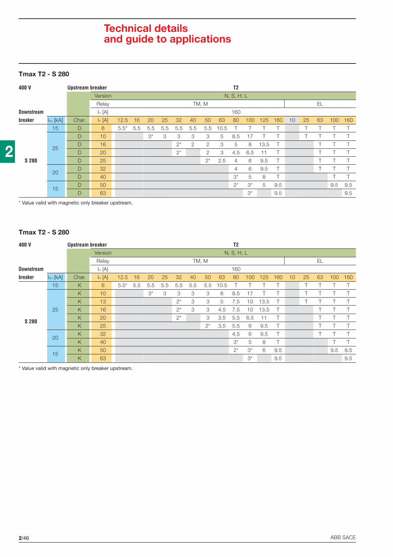
2/46 ABB SACE
2
Tmax T2 - S 280
Tmax T2 - S 280
400 V Upstream breaker T2Version N, S, H, L
Relay TM, M EL
Downstream Iu [A] 160
breaker Icu [kA] Char. In [A] 12.5 16 20 25 32 40 50 63 80 100 125 160 10 25 63 100 160
15 D 6 5.5* 5.5 5.5 5.5 5.5 5.5 5.5 10.5 T T T T T T T T
D 10 3* 3 3 3 3 5 8.5 17 T T T T T T
25D 16 2* 2 2 3 5 8 13.5 T T T T
D 20 2* 2 3 4.5 6.5 11 T T T T
S 280 D 25 2* 2.5 4 6 9.5 T T T T
20D 32 4 6 9.5 T T T T
D 40 3* 5 8 T T T
15D 50 2* 3* 5 9.5 9.5 9.5
D 63 3* 9.5 9.5
* Value valid with magnetic only breaker upstream.
400 V Upstream breaker T2Version N, S, H, L
Relay TM, M EL
Downstream Iu [A] 160
breaker Icu [kA] Char. In [A] 12.5 16 20 25 32 40 50 63 80 100 125 160 10 25 63 100 160
15 K 6 5.5* 5.5 5.5 5.5 5.5 5.5 5.5 10.5 T T T T T T T T
K 10 3* 3 3 3 3 6 8.5 17 T T T T T T
K 13 2* 3 3 5 7.5 10 13.5 T T T T T
25 K 16 2* 3 3 4.5 7.5 10 13.5 T T T T
S 280K 20 2* 3 3.5 5.5 6.5 11 T T T T
K 25 2* 3.5 5.5 6 9.5 T T T T
20K 32 4.5 6 9.5 T T T T
K 40 3* 5 8 T T T
15K 50 2* 3* 6 9.5 9.5 9.5
K 63 3* 9.5 9.5
* Value valid with magnetic only breaker upstream.
Technical detailsand guide to applications
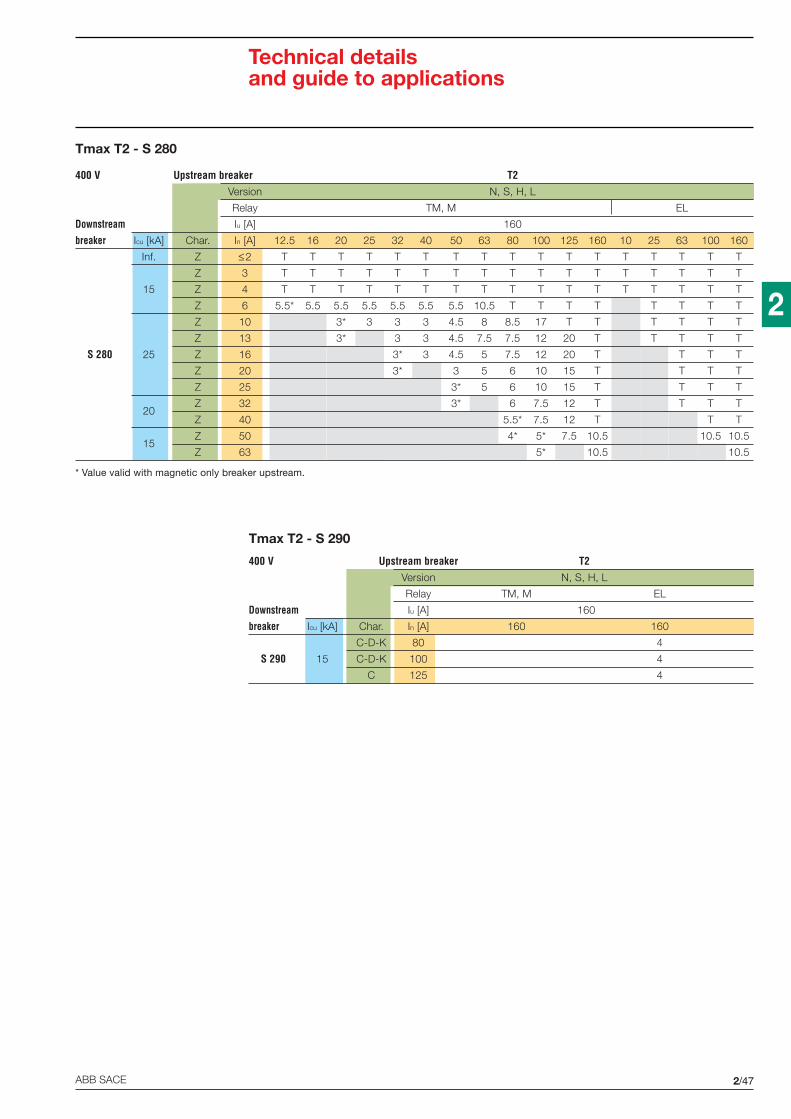
2/47ABB SACE
2
Tmax T2 - S 280
Tmax T2 - S 290
400 V Upstream breaker T2Version N, S, H, L
Relay TM, M EL
Downstream Iu [A] 160
breaker Icu [kA] Char. In [A] 12.5 16 20 25 32 40 50 63 80 100 125 160 10 25 63 100 160
Inf. Z ≤2 T T T T T T T T T T T T T T T T T
Z 3 T T T T T T T T T T T T T T T T T
15 Z 4 T T T T T T T T T T T T T T T T T
Z 6 5.5* 5.5 5.5 5.5 5.5 5.5 5.5 10.5 T T T T T T T T
Z 10 3* 3 3 3 4.5 8 8.5 17 T T T T T T
Z 13 3* 3 3 4.5 7.5 7.5 12 20 T T T T T
S 280 25 Z 16 3* 3 4.5 5 7.5 12 20 T T T T
Z 20 3* 3 5 6 10 15 T T T T
Z 25 3* 5 6 10 15 T T T T
20Z 32 3* 6 7.5 12 T T T T
Z 40 5.5* 7.5 12 T T T
15Z 50 4* 5* 7.5 10.5 10.5 10.5
Z 63 5* 10.5 10.5
* Value valid with magnetic only breaker upstream.
400 V Upstream breaker T2Version N, S, H, L
Relay TM, M EL
Downstream Iu [A] 160
breaker Icu [kA] Char. In [A] 160 160
C-D-K 80 4
S 290 15 C-D-K 100 4
C 125 4
Technical detailsand guide to applications

2/48 ABB SACE
2
Tmax T2 - S 500
Tmax T2 - S 500
400 V Upstream breaker T2Version N, S, H, L
Relay TM, M EL
Downstream Iu [A] 160
breaker Icu [kA] Char. In [A] 12.5 16 20 25 32 40 50 63 80 100 125 160 10 25 63 100 160
B-C-D 6 4.5 5.5 5.5 5.5 5.5 5.5 5.5 10.5 15 20 25 36 36 36 36 36
B-C-D 10 4.5* 4.5 4.5 4.5 4.5 8 10 20 25 36 36 36 36 36
B-C-D 13 4.5* 4.5 4.5 4.5 7.5 10 15 25 36 36 36 36 36
B-C-D 16 4.5* 4.5 4.5 7.5 10 15 25 36 36 36 36
S 500 50B-C-D 20 4.5* 4.5 7.5 10 15 25 36 36 36 36
B-C-D 25 4.5* 6 10 15 20 36 36 36 36
B-C-D 32 4.5* 7.5 10 20 36 36 36 36
B-C-D 40 5* 10 20 36 36 36
B-C-D 50 5* 7.5* 15 36 36 36
B-C-D 63 5* 36 36
* Value valid with magnetic only breaker upstream.
400 V Upstream breaker T2Version N, S, H, L
Relay TM, M EL
Downstream Iu [A] 160
breaker Icu [kA] Char. In [A] 12.5 16 20 25 32 40 50 63 80 100 125 160 10 25 63 100 160
K ≤5.8 36 36 36 36 36 36 36 36 36 36 36 50** 50** 50** 50** 50** 50**
50 K 5.3...8 4.5* 5.5 5.5 5.5 5.5 5.5 5.5 10.5 36 36 36 50** 50** 50** 50** 50**
K 7.3...11 4.5* 4.5 4.5 4.5 4.5 8 36 36 36 50** 50** 50** 50** 50**
K 10...15 4.5* 4.5 4.5 4.5 7.5 10 15 T T T T T T
S 500K 14...20 4.5* 4.5 4.5 7.5 10 15 T T T T T
K 18...26 4.5* 4.5 7.5 10 15 T T T T T
30 K 23...32 4.5* 6 10 15 20 T T T T
K 29...37 4.5* 7.5 10 20 T T T
K 34...41 5* 10 20 T T T
K 38...45 5* 7.5* 15 T T T
* Value valid with magnetic only breaker upstream.** Consider the lower value between the breaking capacity of the upstream circuit-breaker and the value indicated.
Technical detailsand guide to applications

2/49ABB SACE
2
Tmax T3 - S 240
Tmax T3 - S 250
400 V Upstream breaker T3Version N, S
Relay TM, M
Downstream Iu [A] 250
breaker Icu [kA] Char. In [A] 63 80 100 125 160 200 250
C ≤2 T T T T T T T
C 3 T T T T T T T
C 4 T T T T T T T
B-C 6 T T T T T T T
B-C 8 T T T T T T T
B-C 10 7.5 8.5 T T T T T
S 250 10B-C 13 7.5 7.5 T T T T T
B-C 16 5 7.5 T T T T T
B-C 20 5 6 T T T T T
B-C 25 5 6 T T T T T
B-C 32 6 7.5 T T T T
B-C 40 7.5 T T T T
B-C 50 5* 7.5 T T T
B-C 63 5* 6* T T T
* Value valid with magnetic only breaker upstream.
400 V Upstream breaker T3Version N, S
Relay TM, M
Downstream Iu [A] 250
breaker Icu [kA] Char. In [A] 63 80 100 125 160 200 250
C 6 T T T T T T T
C 8 T T T T T T T
C 10 T T T T T T T
C 13 T T T T T T T
S 240 7.5 C 16 5 T T T T T T
C 20 5 6 T T T T T
C 25 5 6 T T T T T
C 32 6 T T T T T
C 40 4 T T T T T
Technical detailsand guide to applications

2/50 ABB SACE
2
Tmax T3 - S 260
Tmax T3 - S 250
400 V Upstream breaker T3Version N, S
Relay TM, M
Downstream Iu [A] 250
breaker Icu [kA] Char. In [A] 63 80 100 125 160 200 250
K ≤2 T T T T T T T
K 3 T T T T T T T
K 4 T T T T T T T
K 6 T T T T T T T
K 8 T T T T T T T
K 10 6 8.5 T T T T T
S 250 10 K 16 4.5 7.5 T T T T T
K 20 3.5 5.5 6.5 T T T T
K 25 3.5 5.5 6 9.5 T T T
K 32 4.5 6 9.5 T T T
K 40 5 8 T T T
K 50 3* 6 9.5 T T
K 63 3* 5.5* 9.5 T T
400 V Upstream breaker T3Version N, S
Relay TM, M
Downstream Iu [A] 250
breaker Icu [kA] Char. In [A] 63 80 100 125 160 200 250
C ≤2 T T T T T T T
C 3 T T T T T T T
C 4 T T T T T T T
B-C 6 T T T T T T T
B-C 8 T T T T T T T
B-C 10 7.5 8.5 T T T T T
S 260 10B-C 13 7.5 7.5 T T T T T
B-C 16 5 7.5 T T T T T
B-C 20 5 6 T T T T T
B-C 25 5 6 T T T T T
B-C 32 6 7.5 T T T T
B-C 40 7.5 T T T T
B-C 50 5* 7.5 T T T
B-C 63 5* 6* T T T
Technical detailsand guide to applications
* Value valid with magnetic only breaker upstream.
* Value valid with magnetic only breaker upstream.

2/51ABB SACE
2
Tmax T3 - S 270
Tmax T3 - S 270
* Value valid with magnetic only breaker upstream.
400 V Upstream breaker T3Version N, S
Relay TM, M
Downstream Iu [A] 250
breaker Icu [kA] Char. In [A] 63 80 100 125 160 200 250
C ≤2 T T T T T T T
C 3 T T T T T T T
C 4 T T T T T T T
B-C 6 10.5 T T T T T T
B-C 8 10.5 T T T T T T
B-C 10 7.5 8.5 T T T T T
S 270 15B-C 13 7.5 7.5 12 T T T T
B-C 16 5 7.5 12 T T T T
B-C 20 5 6 10 T T T T
B-C 25 5 6 10 T T T T
B-C 32 6 7.5 12 T T T
B-C 40 7.5 12 T T T
B-C 50 5* 7.5 10.5 T T
B-C 63 5* 6* 10.5 T T
* Value valid with magnetic only breaker upstream.
400 V Upstream breaker T3Version N, S
Relay TM, M
Downstream Iu [A] 250
breaker Icu [kA] Char. In [A] 63 80 100 125 160 200 250
D ≤2 T T T T T T T
D 3 T T T T T T T
D 4 T T T T T T T
D 6 10.5 T T T T T T
D 8 10.5 12 T T T T T
D 10 5 8.5 T T T T T
S 270 15 D 16 3 5 8 13.5 T T T
D 20 3 4.5 6.5 11 T T T
D 25 2.5 4 6 9.5 T T T
D 32 4 6 9.5 T T T
D 40 5 8 T T T
D 50 3* 5 9.5 T T
D 63 3* 5* 9.5 T T
Technical detailsand guide to applications

2/52 ABB SACE
2
Tmax T3 - S 270
Tmax T3 - S 280
* Value valid with magnetic only breaker upstream.
400 V Upstream breaker T3Version N, S
Relay TM, M
Downstream Iu [A] 250
breaker Icu [kA] Char. In [A] 63 80 100 125 160 200 250
Z ≤2 T T T T T T T
Z 3 T T T T T T T
Z 4 T T T T T T T
Z 6 T T T T T T T
Z 8 T T T T T T T
Z 10 8 8.5 T T T T T
S 270 10 Z 16 5 7.5 T T T T T
Z 20 5 6 T T T T T
Z 25 5 6 T T T T T
Z 32 6 7.5 T T T T
Z 40 7.5 T T T T
Z 50 5* 7.5 T T T
Z 63 5* 6* T T T
* Value valid with magnetic only breaker upstream.
400 V Upstream breaker T3Version N, S
Relay TM, M
Downstream Iu [A] 250
breaker Icu [kA] Char. In [A] 63 80 100 125 160 200 250
15 B-C 6 10.5 T T T T T T
B-C 10 7.5 8.5 17 T T T T
B-C 13 7.5 7.5 12 20 T T T
25 B-C 16 5 7.5 12 20 T T T
S 280B-C 20 5 6 8 13.5 T T T
B-C 25 5 6 8 13.5 T T T
20B-C 32 6 7.5 12 T T T
B-C 40 7.5 12 T T T
15B-C 50 5* 7.5 10.5 T T
B-C 63 5* 6* 10.5 T T
Technical detailsand guide to applications
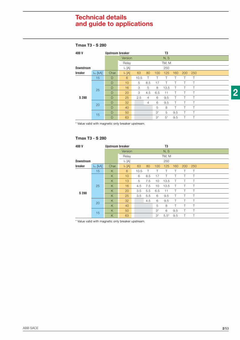
2/53ABB SACE
2
Tmax T3 - S 280
Tmax T3 - S 280
* Value valid with magnetic only breaker upstream.
400 V Upstream breaker T3Version N, S
Relay TM, M
Downstream Iu [A] 250
breaker Icu [kA] Char. In [A] 63 80 100 125 160 200 250
15 K 6 10.5 T T T T T T
K 10 6 8.5 17 T T T T
K 13 5 7.5 10 13.5 T T T
25 K 16 4.5 7.5 10 13.5 T T T
S 280K 20 3.5 5.5 6.5 11 T T T
K 25 3.5 5.5 6 9.5 T T T
20K 32 4.5 6 9.5 T T T
K 40 5 8 T T T
15K 50 3* 6 9.5 T T
K 63 3* 5.5* 9.5 T T
* Value valid with magnetic only breaker upstream.
400 V Upstream breaker T3Version N, S
Relay TM, M
Downstream Iu [A] 250
breaker Icu [kA] Char. In [A] 63 80 100 125 160 200 250
15 D 6 10.5 T T T T T T
D 10 5 8.5 17 T T T T
25D 16 3 5 8 13.5 T T T
D 20 3 4.5 6.5 11 T T T
S 280 D 25 2.5 4 6 9.5 T T T
20D 32 4 6 9.5 T T T
D 40 5 8 T T T
15D 50 3* 5 9.5 T T
D 63 3* 5* 9.5 T T
Technical detailsand guide to applications

2/54 ABB SACE
2
Tmax T3 - S 290
Tmax T3 - S 280
* Value valid with magnetic only breaker upstream.
400 V Upstream breaker T3Version N, S
Relay TM, M
Downstream Iu [A] 250
breaker Icu [kA] Char. In [A] 63 80 100 125 160 200 250
Inf. Z ≤2 T T T T T T T
Z 3 T T T T T T T
15 Z 4 T T T T T T T
Z 6 10.5 T T T T T T
Z 10 8 8.5 17 T T T T
Z 13 7.5 7.5 12 20 T T T
S 280 25 Z 16 5 7.5 12 20 T T T
Z 20 5 6 10 15 T T T
Z 25 5 6 10 15 T T T
20Z 32 6 7.5 12 T T T
Z 40 7.5 12 T T T
15Z 50 5* 7.5 10.5 T T
Z 63 5* 6* 10.5 T T
* Value valid with magnetic only breaker upstream.
400 V Upstream breaker T3Version N, S
Relay TM, M
Downstream Iu [A] 250
breaker Icu [kA] Char. In [A] 160 200 250
C-D-K 80 4* 10 15
S 290 15 C-D-K 100 4* 7.5* 15
C 125 7.5*
Technical detailsand guide to applications

2/55ABB SACE
2
Tmax T3 - S 500
Tmax T3 - S 500
* Value valid with magnetic only breaker upstream.
400 V Upstream breaker T3Version N, S
Relay TM, M
Downstream Iu [A] 250
breaker Icu [kA] Char. In [A] 63 80 100 125 160 200 250
B-C-D 6 10.5 15 20 25 36 36 36
B-C-D 10 8 10 20 25 36 36 36
B-C-D 13 7.5 10 15 25 36 36 36
B-C-D 16 7.5 10 15 25 36 36 36
S 500 50B-C-D 20 7.5 10 15 25 36 36 36
B-C-D 25 6 10 15 20 36 36 36
B-C-D 32 7.5 10 20 36 36 36
B-C-D 40 10 20 36 36 36
B-C-D 50 7.5* 15 36 36 36
B-C-D 63 5* 6* 36 36 36
* Value valid with magnetic only breaker upstream.
400 V Upstream breaker T3Version N, S
Relay TM, M
Downstream Iu [A] 250
breaker Icu [kA] Char. In [A] 63 80 100 125 160 200 250
K ≤5.8 36 36 36 36 T T T
50 K 5.3...8 10.5 36 36 36 T T T
K 7.3...11 8 36 36 36 T T T
K 10...15 7.5 10 15 T T T T
S 500K 14...20 7.5 10 15 T T T T
K 18...26 7.5 10 15 T T T T
30 K 23...32 6 10 15 20 T T T
K 29...37 7.5 10 20 T T T
K 34...41 10 20 T T T
K 38...45 7.5* 15 T T T
Technical detailsand guide to applications
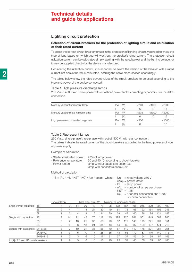
2/56 ABB SACE
2
Technical detailsand guide to applications
Lighting circuit protection
Selection of circuit-breakers for the protection of lighting circuit and calculationof their rated currentTo select the correct circuit-breaker for use in the protection of lighting circuits you need to know thetype of load based on which you will work out the breaker’s rated current. The protection circuitutilization current can be calculated simply starting with the rated power and the lighting voltage, orit may be supplied directly by the device manufacturer.
Considering the utilization current, it is important to select the version of the breaker with a ratedcurrent just above the value calculated, defining the cable cross-section accordingly.
The tables below show the rated current values of the circuit-breakers to be used according to thetype and power of the device connected.
Table 1 High pressure discharge lamps230 V and 400 V a.c. three-phase with or without power factor correcting capacitors, star or deltaconnection
Mercury vapour fluorescent lamp Pw [W] <700 <1000 <2000
I [A] 6 10 16
Mercury vapour metal halogen lamp Pw [W] <375 <1000 <2000
I [A] 6 10 16
High pressure sodium discharge lamp Pw [W] <400 <1000
I [A] 6 16
Table 2 Fluorescent lamps230 V a.c. single-phase/three-phase with neutral (400 V), with star connection.The tables indicate the rated current of the circuit-breakers according to the lamp power and typeof power supply.
Example of calculation
- Starter dissipated power: 25% of lamp power- Reference temperature: 30 and 40 °C according to circuit-breaker- Power factor: lamp without capacitors cosϕ=0.6
lamp with capacitors cosϕ=0.86
Method of calculation
- IB = (PL * n°L * KST * KC) / (Un * cosϕ) where: - Un = rated voltage 230 V- cosϕ = power factor- PL = lamp power- n°L = number of lamps per phase- KST = 1.25- KC = 1 for star connection and 1.732
for delta connection
Type of lamp Tube diss. pwr. [W] Number of lamps per phaseSingle without capacitors 18 4 9 14 29 49 78 98 122 157 196 245 309 392 490
36 2 4 7 14 24 39 49 61 78 98 122 154 196 245
58 1 3 4 9 15 24 30 38 48 60 76 95 121 152
Single with capacitors 18 7 14 21 42 70 112 140 175 225 281 351 443 562 703
36 3 7 10 21 35 56 70 87 112 140 175 221 281 351
58 2 4 6 13 21 34 43 54 69 87 109 137 174 218
Double with capacitors 2x18=36 3 7 10 21 35 56 70 87 112 140 175 221 281 351
2x36=72 1 3 5 10 17 28 35 43 56 70 87 110 140 175
2x58=116 1 2 3 6 10 17 21 27 34 43 54 68 87 109
In [A] - 2P and 4P circuit-breakers 1 2 3 6 10 16 20 25 32 40 50 63 80 100

2/57ABB SACE
2
Transformer protection
Insertion currentWhen the LV/LV transformers are powered up, very strong currents occur, which must be consideredwhen selecting the protective device. The peak value of the first current wave often reaches a valuebetween 10 and 15 times the transformer’s effective rated current.
For power ratings below 50 kVA, it may reach between 20 and 25 times the rated current. Thistransient current decreases very rapidly with a time constant T varying from several ms to 10, 20 ms.
Main protection on the primary sideThe tables below are the result of a set of tests on co-ordination between circuit-breakers and BT/BTtransformers. The transformers used in the tests are normalized. The table, referring to a primarysupply voltage of 230 or 400 V and to single-phase and three-phase transformers, indicate whichcircuit-breaker should be used according to the transformer power rating.
The transformers considered have the primary winding outside the secondary winding.
The circuit-breakers suggested allow:• transformer protection in the event of maximum short-circuit;• prevention of unwanted tripping when the primary winding is powered up using
1. modular circuit-breakers with a high magnetic threshold, curve D or K2. circuit-breakers with magnetic only releaser;
• guaranteed circuit-breaker electrical life.
Protection on the secondary sideDue to the transformer’s high insertion current, the circuit-breaker on the primary winding may notguarantee thermal protection for the transformer and its feeder line on the primary side.
This is typical of modular circuit-breakers which must have a higher rated current than the transformers.In such cases, in the event of a single-phase short-circuit at the transformer’s primary terminals(minimum Icc at end of line), check that the circuit-breaker’s magnetic releaser is tripped. In thenormal application in distribution panels, this condition is always satisfied provided that the length ofthe feeder lines is reduced.
The transformer can be provided with thermal protection by installing a circuit-breaker with a ratedcurrent less than or equal to that of the transformer secondary winding immediately downstream ofthe LV/LV transformer.
Fluorescent lamps. 230V a.c. three-phase – Delta connection
Type of lamp Tube diss. pwr. [W] Number of lamps per phase
Single without capacitors 18 2 5 8 16 28 45 56 70 90 113 141 178 226 283
36 1 2 4 8 14 22 28 35 45 56 70 89 113 141
58 0 1 2 5 8 14 17 21 28 35 43 55 70 87
Single with capacitors 18 4 8 12 24 40 64 81 101 127 162 203 255 324 406
36 2 4 6 12 20 32 40 50 64 81 101 127 162 203
58 1 2 3 7 12 20 25 31 40 50 63 79 100 126
Double with capacitors 2x18=36 2 4 6 12 20 32 40 50 64 81 101 127 162 203
2x36=72 1 2 3 6 10 16 20 25 32 40 50 63 81 101
2x58=116 0 1 1 3 6 10 12 15 20 25 31 39 50 63
In [A] - 3P circuit-break. 1 2 3 6 10 16 20 25 32 40 50 63 80 100
Technical detailsand guide to applications
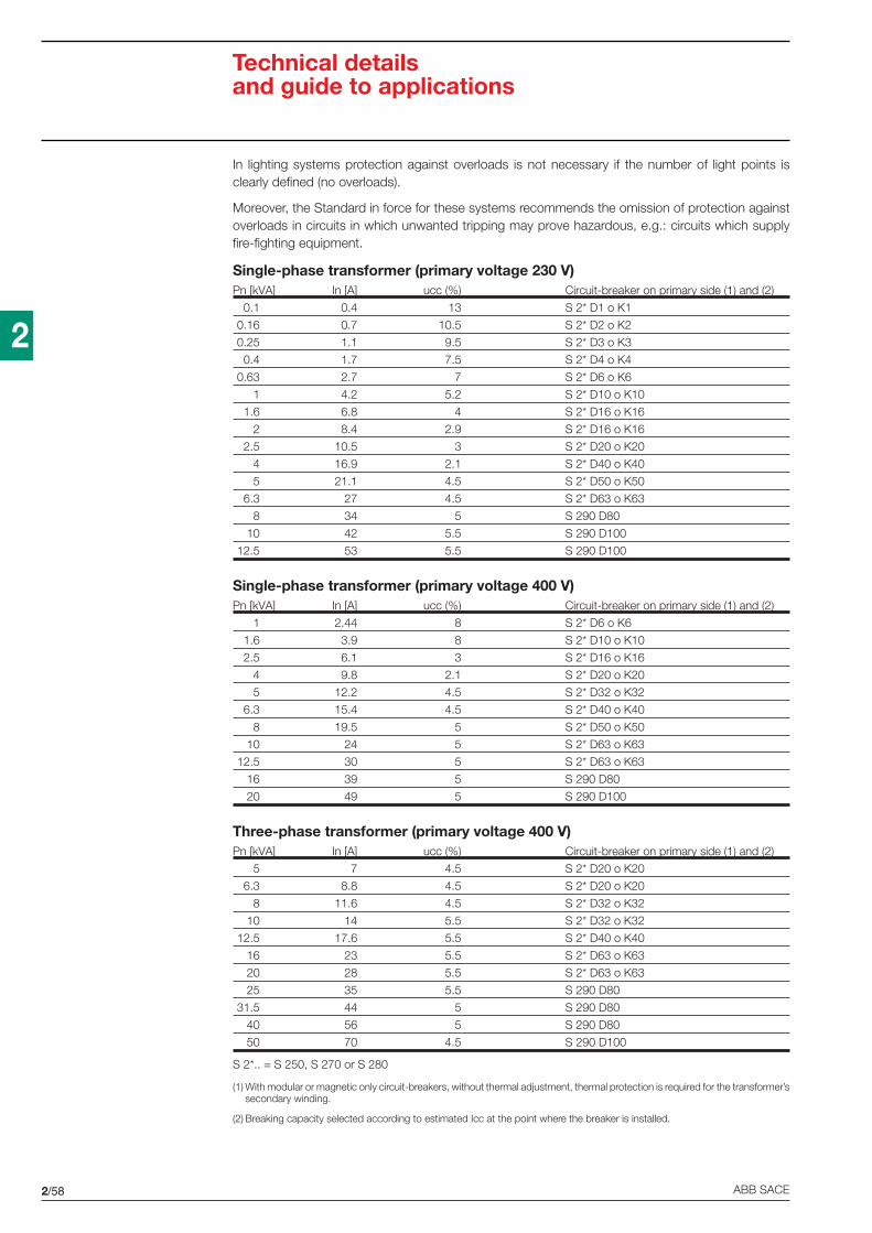
2/58 ABB SACE
2
In lighting systems protection against overloads is not necessary if the number of light points isclearly defined (no overloads).
Moreover, the Standard in force for these systems recommends the omission of protection againstoverloads in circuits in which unwanted tripping may prove hazardous, e.g.: circuits which supplyfire-fighting equipment.
Single-phase transformer (primary voltage 230 V)Pn [kVA] In [A] ucc (%) Circuit-breaker on primary side (1) and (2)
0.1 0.4 13 S 2* D1 o K1
0.16 0.7 10.5 S 2* D2 o K2
0.25 1.1 9.5 S 2* D3 o K3
0.4 1.7 7.5 S 2* D4 o K4
0.63 2.7 7 S 2* D6 o K6
1 4.2 5.2 S 2* D10 o K10
1.6 6.8 4 S 2* D16 o K16
2 8.4 2.9 S 2* D16 o K16
2.5 10.5 3 S 2* D20 o K20
4 16.9 2.1 S 2* D40 o K40
5 21.1 4.5 S 2* D50 o K50
6.3 27 4.5 S 2* D63 o K63
8 34 5 S 290 D80
10 42 5.5 S 290 D100
12.5 53 5.5 S 290 D100
Single-phase transformer (primary voltage 400 V)Pn [kVA] In [A] ucc (%) Circuit-breaker on primary side (1) and (2)
1 2.44 8 S 2* D6 o K6
1.6 3.9 8 S 2* D10 o K10
2.5 6.1 3 S 2* D16 o K16
4 9.8 2.1 S 2* D20 o K20
5 12.2 4.5 S 2* D32 o K32
6.3 15.4 4.5 S 2* D40 o K40
8 19.5 5 S 2* D50 o K50
10 24 5 S 2* D63 o K63
12.5 30 5 S 2* D63 o K63
16 39 5 S 290 D80
20 49 5 S 290 D100
Three-phase transformer (primary voltage 400 V)Pn [kVA] In [A] ucc (%) Circuit-breaker on primary side (1) and (2)
5 7 4.5 S 2* D20 o K20
6.3 8.8 4.5 S 2* D20 o K20
8 11.6 4.5 S 2* D32 o K32
10 14 5.5 S 2* D32 o K32
12.5 17.6 5.5 S 2* D40 o K40
16 23 5.5 S 2* D63 o K63
20 28 5.5 S 2* D63 o K63
25 35 5.5 S 290 D80
31.5 44 5 S 290 D80
40 56 5 S 290 D80
50 70 4.5 S 290 D100
S 2*.. = S 250, S 270 or S 280
(1) With modular or magnetic only circuit-breakers, without thermal adjustment, thermal protection is required for the transformer’ssecondary winding.
(2) Breaking capacity selected according to estimated Icc at the point where the breaker is installed.
Technical detailsand guide to applications
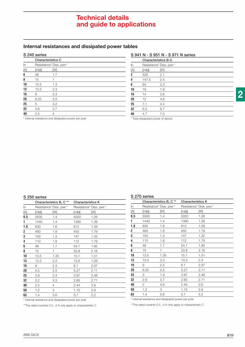
2/59ABB SACE
2
Technical detailsand guide to applications
Internal resistances and dissipated power tables
S 941 N - S 951 N - S 971 N seriesCharacteristics B-C
In Resistance* Diss. pwr.*
[A] [mΩ] [W]
2 520 2.1
4 147.5 2.4
6 64 2.3
10 19 1.9
16 14 3.6
20 12 4.8
25 7.1 4.4
32 6.5 6.7
40 4.7 7.5* Total dissipated power of device
S 240 seriesCharacteristics C
In Resistance* Diss. pwr.*
[A] [mΩ] [W]
6 48 1.7
8 15 1
10 13.3 1.3
13 13.3 2.3
16 9 2.3
20 6.25 2.5
25 5 3.2
32 3.6 3.7
40 2.5 4* Internal resistance and dissipated power per pole
S 250 seriesCharacteristics B, C ** Characteristics K
In Resistance* Diss. pwr.* Resistance* Diss. pwr.*
[A] [mΩ] [W] [mΩ] [W]
0.5 5500 1.4 5020 1.26
1 1440 1.4 1390 1.39
1.6 630 1.6 612 1.56
2 460 1.8 450 1.79
3 150 1.3 147 1.32
4 110 1.8 112 1.79
6 48 1.7 54.1 1.95
8 15 1 33.8 2.16
10 13.5 1.35 15.1 1.51
13 13.3 2.3 12.6 1.26
16 9 2.3 8.1 2.07
20 4.5 2.5 5.27 2.11
25 3.8 2.4 3.97 2.48
32 3.2 3.3 2.65 2.71
40 2.5 4 2.44 3.9
50 1.2 3 1.15 2.9
63 1.4 5.6 0.7 5.2* Internal resistance and dissipated power per pole
**The rated currents 0.5...4 A only apply to characteristic C
S 270 seriesCharacteristics B, C ** Characteristics K
In Resistance* Diss. pwr.* Resistance* Diss. pwr.*
[A] [mΩ] [W] [mΩ] [W]
0.5 5500 1.4 5020 1.26
1 1440 1.4 1390 1.39
1.6 630 1.6 612 1.56
2 460 1.8 450 1.79
3 150 1.3 147 1.32
4 110 1.8 112 1.79
6 48 1.7 54.1 1.95
8 15 1 33.8 2.16
10 13.5 1.35 15.1 1.51
13 13.3 2.3 13.3 2.3
16 9 2.3 8.1 2.07
20 6.25 2.5 5.27 2.11
25 3 1.9 3.97 2.48
32 2.9 3.7 2.65 2.71
40 2 4.8 2.44 3.9
50 1.2 3 1.15 2.9
63 1.4 5.6 0.7 5.2* Internal resistance and dissipated power per pole
**The rated currents 0.5...4 A only apply to characteristic C
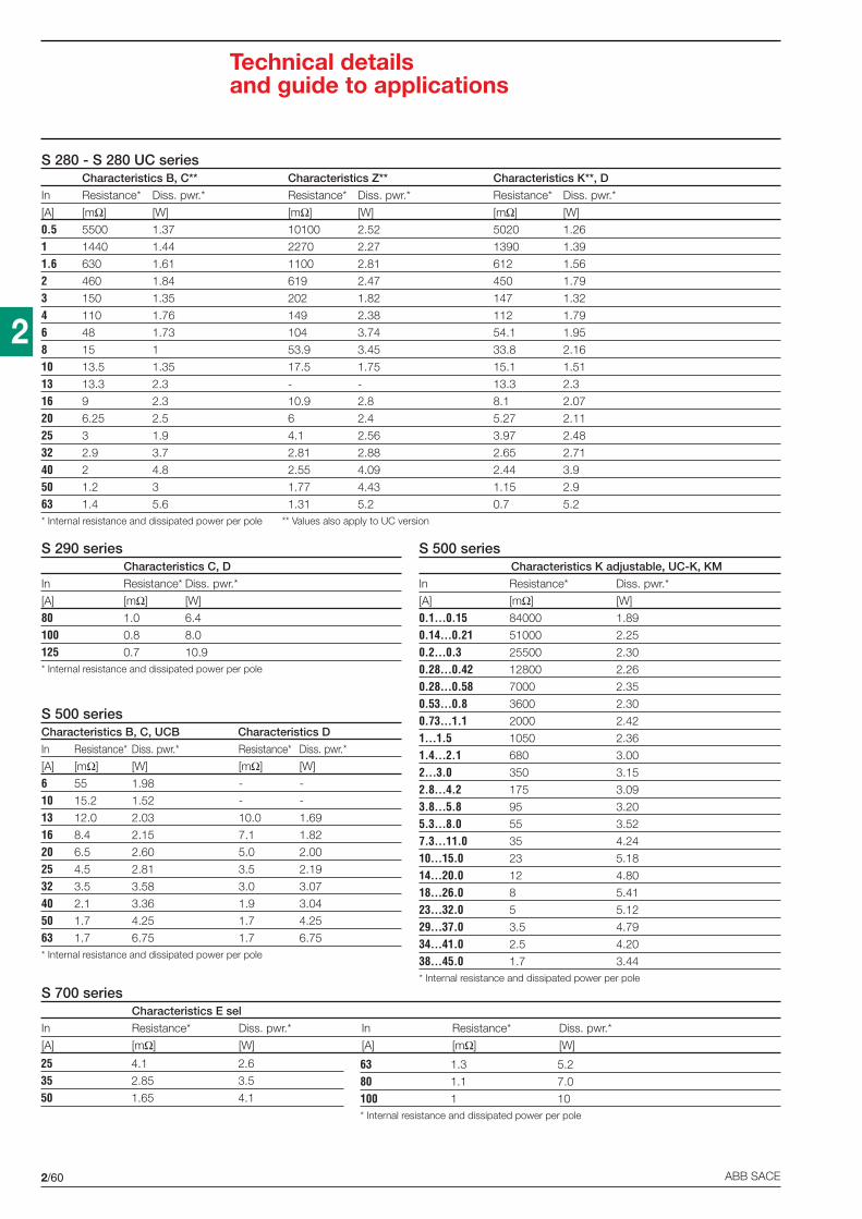
2/60 ABB SACE
2
Technical detailsand guide to applications
S 280 - S 280 UC seriesCharacteristics B, C** Characteristics Z** Characteristics K**, D
In Resistance* Diss. pwr.* Resistance* Diss. pwr.* Resistance* Diss. pwr.*
[A] [mΩ] [W] [mΩ] [W] [mΩ] [W]
0.5 5500 1.37 10100 2.52 5020 1.26
1 1440 1.44 2270 2.27 1390 1.39
1.6 630 1.61 1100 2.81 612 1.56
2 460 1.84 619 2.47 450 1.79
3 150 1.35 202 1.82 147 1.32
4 110 1.76 149 2.38 112 1.79
6 48 1.73 104 3.74 54.1 1.95
8 15 1 53.9 3.45 33.8 2.16
10 13.5 1.35 17.5 1.75 15.1 1.51
13 13.3 2.3 - - 13.3 2.3
16 9 2.3 10.9 2.8 8.1 2.07
20 6.25 2.5 6 2.4 5.27 2.11
25 3 1.9 4.1 2.56 3.97 2.48
32 2.9 3.7 2.81 2.88 2.65 2.71
40 2 4.8 2.55 4.09 2.44 3.9
50 1.2 3 1.77 4.43 1.15 2.9
63 1.4 5.6 1.31 5.2 0.7 5.2* Internal resistance and dissipated power per pole ** Values also apply to UC version
S 290 seriesCharacteristics C, D
In Resistance* Diss. pwr.*
[A] [mΩ] [W]
80 1.0 6.4
100 0.8 8.0
125 0.7 10.9* Internal resistance and dissipated power per pole
S 500 seriesCharacteristics B, C, UCB Characteristics D
In Resistance* Diss. pwr.* Resistance* Diss. pwr.*
[A] [mΩ] [W] [mΩ] [W]
6 55 1.98 - -
10 15.2 1.52 - -
13 12.0 2.03 10.0 1.69
16 8.4 2.15 7.1 1.82
20 6.5 2.60 5.0 2.00
25 4.5 2.81 3.5 2.19
32 3.5 3.58 3.0 3.07
40 2.1 3.36 1.9 3.04
50 1.7 4.25 1.7 4.25
63 1.7 6.75 1.7 6.75* Internal resistance and dissipated power per pole
S 500 seriesCharacteristics K adjustable, UC-K, KM
In Resistance* Diss. pwr.*
[A] [mΩ] [W]
0.1...0.15 84000 1.89
0.14...0.21 51000 2.25
0.2...0.3 25500 2.30
0.28...0.42 12800 2.26
0.28...0.58 7000 2.35
0.53...0.8 3600 2.30
0.73...1.1 2000 2.42
1...1.5 1050 2.36
1.4...2.1 680 3.00
2...3.0 350 3.15
2.8...4.2 175 3.09
3.8...5.8 95 3.20
5.3...8.0 55 3.52
7.3...11.0 35 4.24
10...15.0 23 5.18
14...20.0 12 4.80
18...26.0 8 5.41
23...32.0 5 5.12
29...37.0 3.5 4.79
34...41.0 2.5 4.20
38...45.0 1.7 3.44* Internal resistance and dissipated power per pole
S 700 seriesCharacteristics E sel
In Resistance* Diss. pwr.* In Resistance* Diss. pwr.*
[A] [mΩ] [W] [A] [mΩ] [W]
25 4.1 2.6
35 2.85 3.5
50 1.65 4.1
63 1.3 5.2
80 1.1 7.0
100 1 10* Internal resistance and dissipated power per pole

2/61ABB SACE
2
Technical detailsand guide to applications
Influence of ambient temperature oneffective capacity and rated current
The rated value of the current of a miniature circuit-breaker refersto a temperature of 20 °C for circuit-breakers with characteristicsK and Z and 30 °C for characteristics B, C and D.
For other temperatures, consider a factor (Fc) multiplied by therated current of the device to obtain the non-tripping current (Inf)for the new temperature.
The change in the Fc factor depending on ambient temparature,rated current of the circuit-breaker and the characteristic type isshown in the two graphs below. The rated current (equivalent) forthe new temperature is obtained by dividing the non-tripping cur-rent by the factor of 1.13 for circuit-breakers with characteristics
Influence of ambient temperature
Inf= In • Fc (NON-tripping current)
Influence of ambient temperature
Inf= In • Fc (NON-tripping current)
Influence of adjacent devices
OE
PM
0106
OE
PM
0107
OE
PM
0108
Influence of adjacent devicesCorrection factor Fm
No. of adjacent devices Fm
1 1
2 0.95
3 0.9
4 0.86
5 0.82
6 0.795
7 0.78
8 0.77
9 0.76
>9 0.76
B, C or D and by the factor of 1.05 for circuit-breakers withcharacteristics K or Z.
The following page contains two tables in which this calculationhas been effected for temperatures from -25 °C to +55 °C for thecurves B, C, D, K and Z.
This derating is sufficient for loads which last for less than an hour;for loads which last for more than an hour, multiply the rated cur-rent (equivalent) referring to the new temperature by another fac-tor of 0.9.
A variation in the tripping current is also caused by the presenceof several devices installed alongside each other; in this case, con-sider the factor Fm according to the number of adjacent devices(see table).
Fc fa
ctor
K and Z
Ambient temperature °C
13…32 A
10 A
0,5…8 A and40…63 A
-25 -10 0 10 20 30 40 55
0.8
0.9
1
1.1
1.2
1.3
1.4
1.5
Rated current
S 280S 270S 250
Fc
fact
or
Ambient temperature °C
13…32 A10 A
0,5…8 A and40…63 A
-25 -10 0 10 20 30 40 55
0.8
0.9
1
1.1
1.2
1.3
1.4
1.5
Rated current
S 280S 270S 250
B - C - D
S 240
Fm
fact
or
Devices number
1 2 3 4 5 6 7 8 90.6
0.7
0.8
0.9
1.0

2/62 ABB SACE
2
Example: S 252 C 16 with T=35 °C
Type of use Values to use Formula Calculation Result
Load less In (amb. t°)than an hour -see tables- In=15.43 A
Load more In (amb. t°)than an hour -see tables-, 0.9 In (amb. t°)x0.9 15.43x0.9 In=13.9 A
Load over an hour In (amb. t°)with 8 adj.devices -see tables-, 0.9, Fm (0.77) In (amb. t°)x0.9x0.77 15.43x0.9x0.77 In=10.7 A
Equivalent rated current according to ambient temperature
MINIATURE CIRCUIT-BREAKERS S 240 - S 250 - S 270 - S 280 SERIES - CHARACTERISTICS B-C-D
In
In temp -25 °C -20 °C -15 °C -10 °C -5 °C 0 °C 5 °C 10 °C 15 °C 20 °C 25 °C 30 °C 35 °C 40 °C 45 °C 50 °C 55 °C0.5 0.64 0.63 0.62 0.60 0.59 0.58 0.57 0.55 0.54 0.53 0.51 0.5 0.48 0.46 0.45 0.43 0.41
1 1.28 1.26 1.23 1.20 1.18 1.15 1.13 1.10 1.08 1.05 1.03 1 0.96 0.93 0.89 0.86 0.82
1.6 2.05 2.01 1.97 1.93 1.88 1.84 1.81 1.77 1.73 1.68 1.64 1.6 1.54 1.49 1.43 1.37 1.32
2 2.57 2.51 2.46 2.41 2.35 2.30 2.27 2.21 2.16 2.11 2.05 2 1.93 1.86 1.79 1.72 1.65
3 3.85 3.77 3.69 3.61 3.53 3.45 3.40 3.31 3.24 3.16 3.08 3 2.89 2.79 2.68 2.58 2.47
4 5.13 5.03 4.92 4.81 4.71 4.60 4.53 4.42 4.32 4.21 4.11 4 3.86 3.72 3.58 3.43 3.29
6 7.06 6.98 6.88 6.77 6.72 6.64 6.53 6.42 6.37 6.27 6.11 6 5.79 5.68 5.58 5.47 5.31
8 9.42 9.31 9.17 9.03 8.96 8.85 8.71 8.57 8.50 8.35 8.14 8 7.72 7.58 7.43 7.29 7.08
10 12.83 12.57 12.30 12.04 11.77 11.50 11.33 11.04 10.80 10.53 10.27 10 9.65 9.29 8.94 8.58 8.23
13 16.11 15.82 15.53 15.19 14.96 14.61 14.38 14.15 13.81 13.58 13.23 13 12.54 12.37 11.96 11.50 11.16
16 19.82 19.47 19.12 18.69 18.41 17.98 17.70 17.42 16.99 16.71 16.28 16 15.43 15.22 14.73 14.16 13.73
20 24.78 24.34 23.89 23.36 23.01 22.48 22.12 21.77 21.24 20.88 20.35 20 19.29 19.03 18.41 17.70 17.17
25 30.97 30.42 29.87 29.20 28.76 28.10 27.65 27.21 26.55 26.11 25.44 25 24.12 23.78 23.01 22.12 21.46
32 39.65 38.94 38.23 37.38 36.81 35.96 35.40 34.83 33.98 33.42 32.57 32 30.87 30.44 29.45 28.32 27.47
40 47.08 46.55 45.84 45.13 44.78 44.25 43.54 42.83 42.48 41.77 40.71 40 38.58 37.88 37.17 36.46 35.40
50 58.85 58.19 57.30 56.42 55.97 55.31 54.42 53.54 53.10 52.21 50.88 50 48.23 47.35 46.46 45.58 44.25
63 74.15 73.31 72.20 71.08 70.53 69.69 68.58 67.46 66.90 65.79 64.12 63 60.77 59.65 58.54 57.42 55.75
80 95.57 94.04 92.50 90.97 89.73 88.49 87.08 85.66 84.25 82.83 82.12 80 79.29 78.41 76.11 73.98 72.92
100 119.47 117.55 115.64 113.72 112.17 110.62 108.85 107.08 105.31 103.54 102.65 100 99.11 98.05 95.13 92.48 91.15
MINIATURE CIRCUIT-BREAKERS S 240 - S 250 - S 270 - S 280 SERIES - CHARACTERISTICS K-Z
In
In temp -25 °C -20 °C -15 °C -10 °C -5 °C 0 °C 5 °C 10 °C 15 °C 20 °C 25 °C 30 °C 35 °C 40 °C 45 °C 50 °C 55 °C0.5 0.55 0.55 0.54 0.54 0.53 0.52 0.52 0.51 0.51 0.5 0.49 0.49 0.48 0.47 0.45 0.44 0.43
1 1.10 1.10 1.09 1.08 1.07 1.05 1.04 1.02 1.01 1 0.98 0.97 0.95 0.93 0.90 0.89 0.87
1.6 1.77 1.75 1.74 1.72 1.71 1.68 1.66 1.64 1.62 1.6 1.57 1.55 1.52 1.49 1.45 1.42 1.39
2 2.21 2.19 2.17 2.15 2.13 2.10 2.08 2.05 2.03 2 1.96 1.94 1.90 1.87 1.81 1.77 1.73
3 3.31 3.29 3.26 3.23 3.20 3.14 3.11 3.07 3.04 3 2.94 2.91 2.86 2.80 2.71 2.66 2.60
4 4.42 4.38 4.34 4.30 4.27 4.19 4.15 4.10 4.06 4 3.92 3.89 3.81 3.73 3.62 3.54 3.47
6 6.63 6.57 6.51 6.46 6.40 6.29 6.23 6.14 6.09 6 5.89 5.83 5.71 5.60 5.43 5.31 5.20
8 8.84 8.76 8.69 8.61 8.53 8.38 8.30 8.19 8.11 8 7.85 7.77 7.62 7.47 7.24 7.09 6.93
10 12.38 12.19 11.90 11.52 11.33 11.05 10.76 10.48 10.29 10 9.81 9.33 9.05 8.57 8.29 7.81 7.52
13 15.35 15.17 14.98 14.73 14.49 14.11 13.87 13.62 13.25 13 12.75 12.38 12.13 11.76 11.39 10.77 10.52
16 18.90 18.67 18.44 18.13 17.83 17.37 17.07 16.76 16.30 16 15.70 15.24 14.93 14.48 14.02 13.26 12.95
20 23.62 23.33 23.05 22.67 22.29 21.71 21.33 20.95 20.38 20 19.62 19.05 18.67 18.10 17.52 16.57 16.19
25 29.52 29.17 28.81 28.33 27.86 27.14 26.67 26.19 25.48 25 24.52 23.81 23.33 22.62 21.90 20.71 20.24
32 37.79 37.33 36.88 36.27 35.66 34.74 34.13 33.52 32.61 32 31.39 30.48 29.87 28.95 28.04 26.51 25.90
40 44.19 43.81 43.43 43.05 42.67 41.90 41.52 40.95 40.57 40 39.24 38.86 38.10 37.33 36.19 35.43 34.67
50 55.24 54.76 54.29 53.81 53.33 52.38 51.90 51.19 50.71 50 49.05 48.57 47.62 46.67 45.24 44.29 43.33
63 69.60 69.00 68.40 67.80 67.20 66.00 65.40 64.50 63.90 63 61.80 61.20 60.00 58.80 57.00 55.80 54.60
Technical detailsand guide to applications

2/63ABB SACE
2
Variation in alarm thresholds according to network frequency
The circuit-breakers are calibrated for a current with a frequency range between 50 and 60 Hz.
For other frequency values, the electro-magnetic tripping current varies according to the multiplicationfactor H.
100 Hz 200 Hz 400 Hz d.c.
H 1.1 1.2 1.5 1.5
For the thermal trip, on the other hand, there is no variation because it is independent of the networkfrequency.
Applications in d.c. of standard circuit-breakers
Direct current is used because of the need for a source of energy which is able to power essentialservices such as protection systems, emergency lighting, alarm systems, uninterruptible powersupplies with extreme reliability even in the absence of normal energy sources.
Storage batteries, buffer-powered from the network and installed near the users, are the safestsource of energy for powering these services.
In most cases, the rated voltage of these installations lies between 24 and 220 V; higher voltages arenot, however, excluded (even up to 1000 V).
When selecting circuit-breakers, it is important to bear in mind that leakage currents are very highnear power sources due to the low internal resistance of the batteries.
The main applications of circuit-breakers used in circuits in d.c. include:
- electric traction
- industrial plants with electrolithic processes
- units for rapid drop-out of synchronous machines.
For use in d.c., most standard circuit-breakers can be used, as long as the relevant voltage limits arerespected, as well as the special versions.
It is important to remember that the electro-magnetic trip value in d.c. is approx. 1.5-1.6 times thecorresponding value in a.c.
Standard circuit-breakersSeries Max. permitted voltage
S 240, S 250, S 270, S 280 60 V d.c. for one-pole circuit-breakers
125 V d.c. for two-pole circuit-breakers
S 290 60 V d.c. for one-pole circuit-breakers
125 V d.c. for two-pole circuit-breakers
S 500 250 V d.c. for two-pole circuit-breakers
Special UC (Universal Current) circuit-breakersSeries Max. permitted voltage
S 280 UC 440 V d.c. for two-pole circuit-breakers
S 500 UC 750 V d.c. for three-pole circuit-breakers
Technical detailsand guide to applications

2/64 ABB SACE
2
Max. voltage250 V .... 440 V .... 440 V .... 440 V ....
440 V ....between terminals voltage reversal
Max. voltage between250 V .... 250 V .... 440 V .... (1) 250 V .... 250 V ....terminals and earth
Modular circuit- One-pole Two-pole Two-pole Two-pole Four-pole (2)breaker S 281 UC S 282 UC S 282 UC S 282 UC S 284 UC
Power supplyfrom bottom
Power supplyfrom top
(1) In the interruption example, the negative pole is earthed
Max. voltage 440 V .... 440 V .... 440 V ....between terminals interruption of both poles interruption of 1 pole interruption of both poles
Max. voltage between 250 V 440 V 440 Vterminals and earth power supply with unearthed network or with unearthed network or with
symmetrical earthing asymmetrical earthing asymmetrical earthing
Modular Two-pole Two-pole Four-pole (2)circuit-breaker S 282 UC S 282 UC S 284 UC
(1) Version with 4 protected poles available on request
1
2
L+
+ –
L–
1
2
L+
+ –
L–
3
4
1
2
L+ L–
3
4
+–
1
2
L+ L–
3
4
+–
M
–+
1
2
L+ L–
3
4
5 7
6 8
(L–) (L+)
2
1
L– L+
4
3
6
5
8
7
(L+) (L–)
2
1
L– L+
4
3
+– +
–
M
2
1
L– L+
4
3
+–
2
1
L– L+
– +
4
3
+–
2
1
L– L+
2
1
4
3
+ –
+ –
2
1
4
3
+ –
+ –
2
1
4
3
6
5
8
7
+ –
+ –
OE
PM
0110
OE
PM
0111
Examples of maximum voltages allowed between terminals according to number ofpoles and wiring
Technical detailsand guide to applications
Examples of high voltages between terminals and earth with equal voltage betweenterminals

3/1ABB SACE
3
Overall dimensions
Contents
MCBs .................................................................................................................................... 3/2
Auxiliary elements ............................................................................................................... 3/4
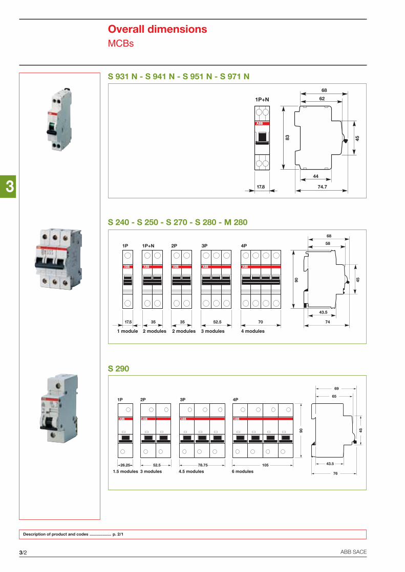
3
3/2 ABB SACE
90 45
76
122.5122.5122.5122.526.25 52.5 78.75 105
1P 2P 3P 4P
1.5 modules 3 modules 4.5 modules 6 modules
43.5
74
68
90 45
17.5
1P
35
1P+N
35
2P
52.5
3P
70
4P
1 module 2 modules 2 modules 3 modules 4 modules
44
74.7
62
83 45
17.8
1P+N
68
43.5
65
69
58
Overall dimensionsMCBs
Description of product and codes ................... p. 2/1
S 931 N - S 941 N - S 951 N - S 971 N
S 240 - S 250 - S 270 - S 280 - M 280
S 290
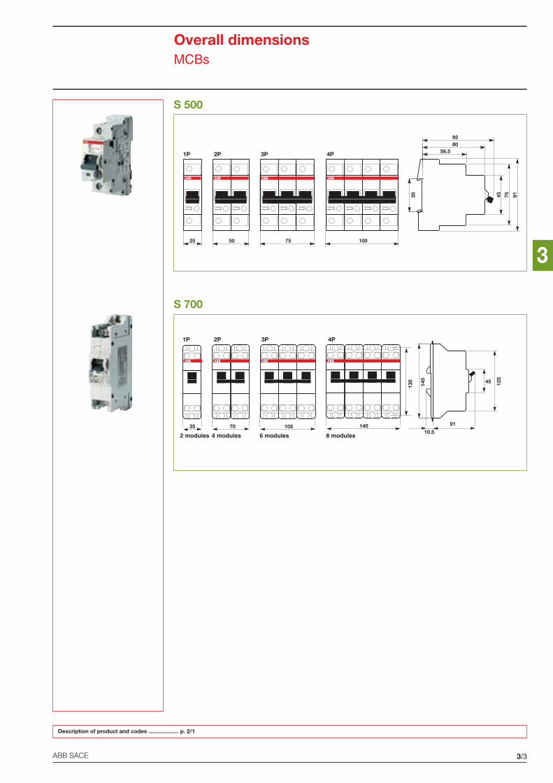
3
3/3ABB SACE
45
91
125
10.535 70 105 140
145
130
1P 2P 3P 4P
2 modules 4 modules 6 modules 8 modules
56.5
4535
100755025
1P 2P 3P 4P
8092
75 91
Overall dimensionsMCBs
S 500
S 700
Description of product and codes ................... p. 2/1
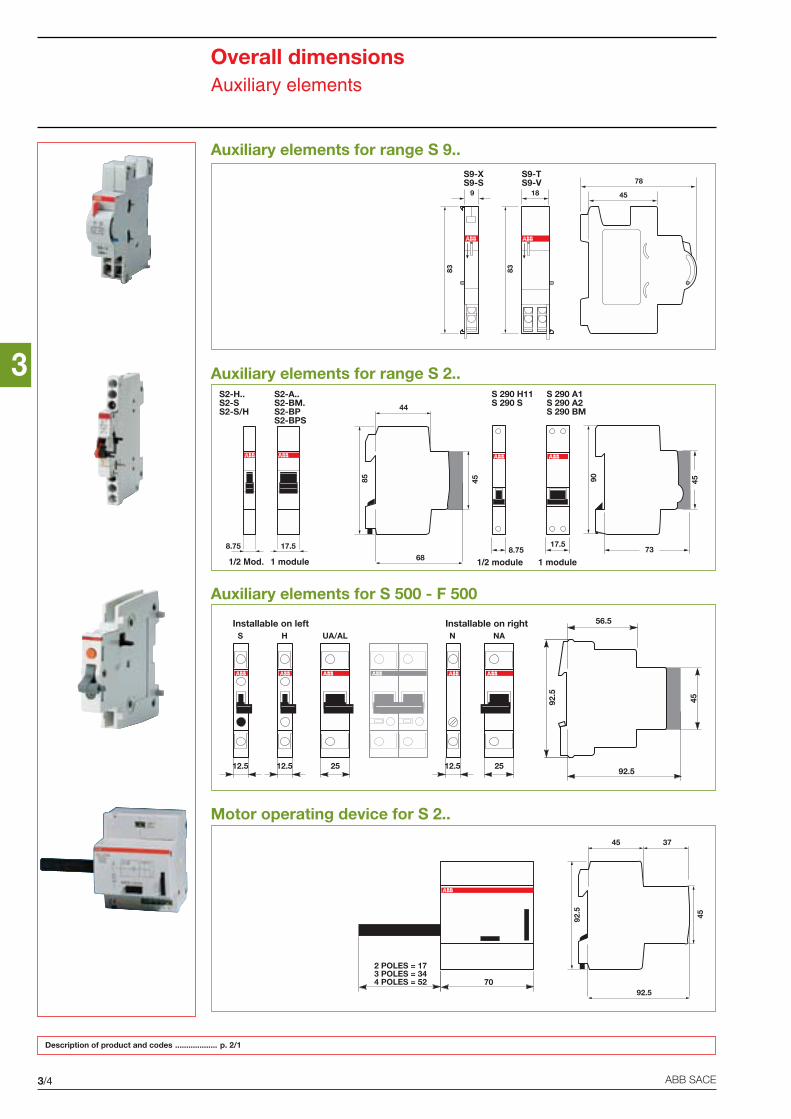
3
3/4 ABB SACE
56.5
4592.5
92.5
Installable on left Installable on right
2525 12.512.512.5
NAUA/AL NHS
85
17.5
44
68
45
8.75
1/2 Mod. 1 module
S2-H..S2-SS2-S/H
S2-A..S2-BM.S2-BPS2-BPS
45
7317.5
1 module
S 290 A1S 290 A2S 290 BM
8.75
1/2 module
S 290 H11S 290 S
90
83 83
189 45
78
92.5
45
92.5
45
37
70
2 POLES = 173 POLES = 344 POLES = 52
S9-XS9-S
S9-TS9-V
Overall dimensionsAuxiliary elements
Description of product and codes ................... p. 2/1
Auxiliary elements for range S 9..
Auxiliary elements for range S 2..
Auxiliary elements for S 500 - F 500
Motor operating device for S 2..

3
3/5ABB SACE
TYPE A B CME 1 - 1 moduleME 2 - 2 modulesME 3 - 3 modulesME 4 - 4 modules
18365472
4057.575.5
93
506785
103ME 6 - 6 modules 108 129 139ME 8 - 8 modules 144 164 172
DEPHT D57 mm for S 240-S 250-S 270-S 280 circuit-breakers
72 mm for S 210 circuit-breakers
80
D
6
72
C
B
47
A
Ø 3.5+4
TYPE A B C D E F G H
PCD/2 25 80 50 35 140 17.5 46 65PCD/4 44 118 96 74 160 17.5 46 65PCD/6 94 125 139 121 160 17.5 46 65PCD/8 183 94 230 178 200 20.5 100 95
B
C
DE
F
H
G
==
A
61.5
339.5
75
F 6-S/HF 3-H11
45
45
45
58
43.5
9.5
75
24.5
22.5
3.2
65
14 34
10
41.5
ø40
M22
x1
Overall dimensionsAuxiliary elements
Auxiliary elements for F 3.. - F 6..
PCD terminal covers
ME flange for rear board mounting
Description of product and codes ................... p. 2/1
OH_2A_

3
3/6 ABB SACE
74.5
6.5
150
4533
79.5
95.5 (1 pole = 90.5)
141
150
34
33 130
10.5
4.5
4040
4040
12
46.4
8.5 104.5
175
66
18.5
N
L1
L2
L3
PE16
35 35
30
78.5
45
83.5
99.5 ( 1 pole = 94.5)
4040
4040
12
175
46.4
23.5
125
EST 2
157
117
115
157
EST 1
Base NH
25.5 34
10
41.5
Ø 4
0
M22
x1
65
24.5
22.5
3.2
36
4836
Ø 4
48
40.7 min. 30 - max. 15080
Overall dimensionsAuxiliary elements
Description of product and codes ................... p. 2/1
Rotary handle for S 500 - F 500
Accessories for S 700
SA flange for S 700
BT1 plate EST
2CS
C40
0001
D02
01 -
Mar
zo ’0
4P
rinte
d in
Ital
y40
00 -
CA
LIn consideration of modifications to Standards and materials,the characteristics and overall dimensions indicated in thiscatalogue may be considered binding only following confirmationby ABB SACE
ABB SACE S.p.AAn ABB Group company
Line Protection DevicesViale dell’Industria, 1820010 Vittuone (MI) - ItalyTel.: +39.02.9034.1 - Telefax: +39.02.9034.7609
http://www.abb.com