Embed Size (px)
Citation preview
PRESSURE REDUCING VALVES EUROPRESS
TECHNICAL CATALOGUE
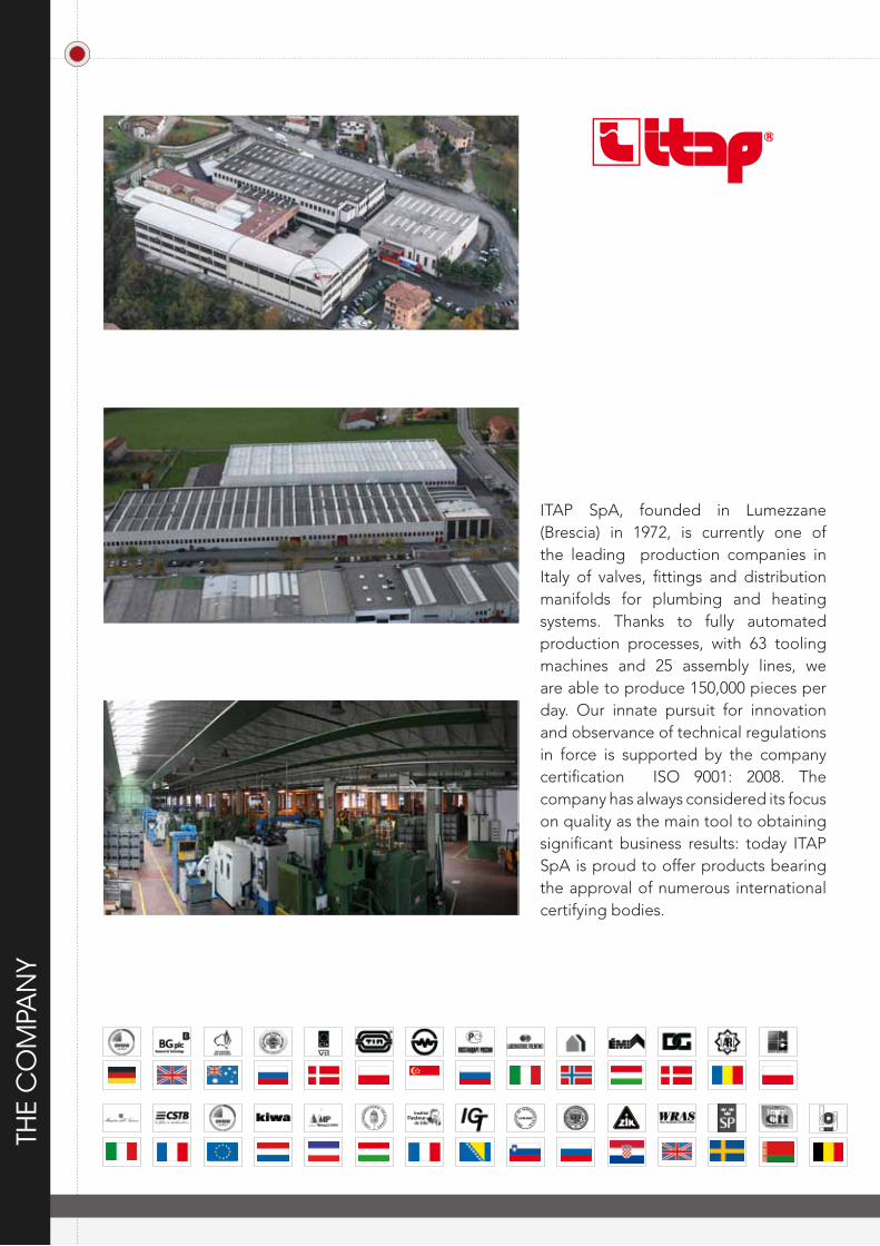
ITAP SpA, founded in Lumezzane (Brescia) in 1972, is currently one of the leading production companies in Italy of valves, fittings and distribution manifolds for plumbing and heating systems. Thanks to fully automated production processes, with 63 tooling machines and 25 assembly lines, we are able to produce 150,000 pieces per day. Our innate pursuit for innovation and observance of technical regulations in force is supported by the company certification ISO 9001: 2008. The company has always considered its focus on quality as the main tool to obtaining significant business results: today ITAP SpA is proud to offer products bearing the approval of numerous international certifying bodies.
THE
CO
MPA
NY
TEC
EUR
OPR
ESS
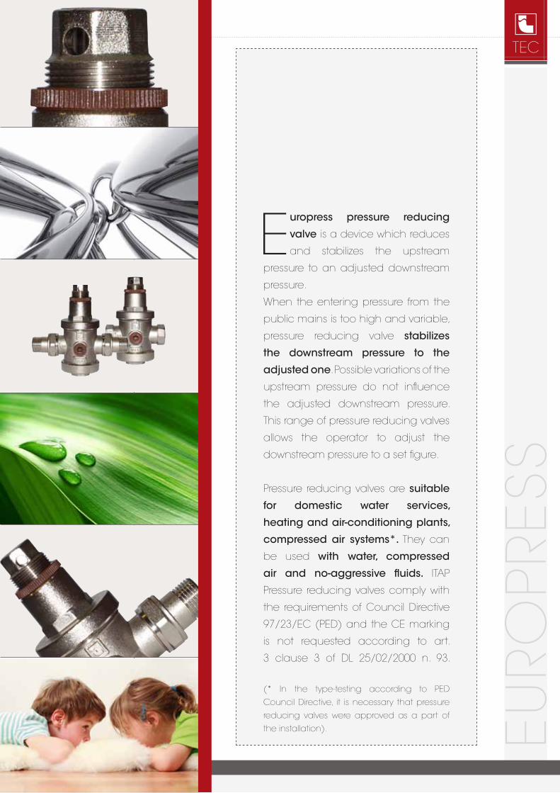
Europress pressure reducing
valve is a device which reduces
and stabilizes the upstream
pressure to an adjusted downstream
pressure.
When the entering pressure from the
public mains is too high and variable,
pressure reducing valve stabilizes
the downstream pressure to the
adjusted one. Possible variations of the
upstream pressure do not influence
the adjusted downstream pressure.
This range of pressure reducing valves
allows the operator to adjust the
downstream pressure to a set figure.
Pressure reducing valves are suitable
for domestic water services,
heating and air-conditioning plants,
compressed air systems*. They can
be used with water, compressed
air and no-aggressive fluids. ITAP
Pressure reducing valves comply with
the requirements of Council Directive
97/23/EC (PED) and the CE marking
is not requested according to art.
3 clause 3 of DL 25/02/2000 n. 93.
(* In the type-testing according to PED
Council Directive, it is necessary that pressure
reducing valves were approved as a part of
the installation).
PRES
SURE
RED
UC
ING
VA
LVES
EUR
OPR
ESS
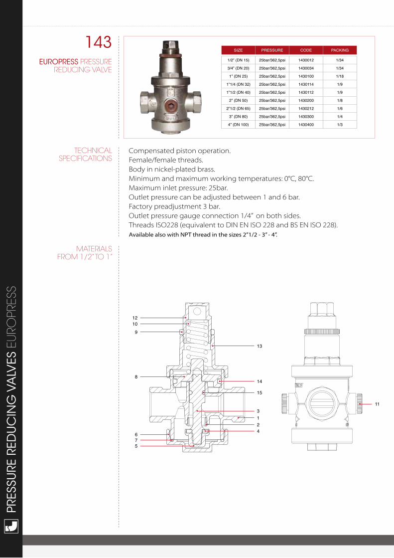
143EUROPRESS PRESSURE
REDUCING VALVE
MATERIALSFROM 1/2” TO 1”
SIZE PRESSURE CODE PACKING
1/2” (DN 15) 25bar/362,5psi 1430012 1/34
3/4” (DN 20) 25bar/362,5psi 1430034 1/34
1” (DN 25) 25bar/362,5psi 1430100 1/18
1”1/4 (DN 32) 25bar/362,5psi 1430114 1/9
1”1/2 (DN 40) 25bar/362,5psi 1430112 1/9
2” (DN 50) 25bar/362,5psi 1430200 1/8
2”1/2 (DN 65) 25bar/362,5psi 1430212 1/6
3” (DN 80) 25bar/362,5psi 1430300 1/4
4” (DN 100) 25bar/362,5psi 1430400 1/3
Compensated piston operation.Female/female threads.Body in nickel-plated brass.Minimum and maximum working temperatures: 0°C, 80°C.Maximum inlet pressure: 25bar.Outlet pressure can be adjusted between 1 and 6 bar.Factory preadjustment 3 bar.Outlet pressure gauge connection 1/4” on both sides.Threads ISO228 (equivalent to DIN EN ISO 228 and BS EN ISO 228).Available also with NPT thread in the sizes 2”1/2 - 3” - 4”.
12109
8
75
6
11
13
14
15
124
3
TEChNICALSPECIFICATIONS
TEC
12
109
8
16
76
5
17
11
13
14
1
3
24
18
15
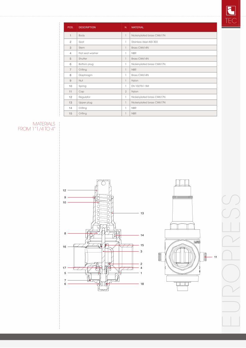
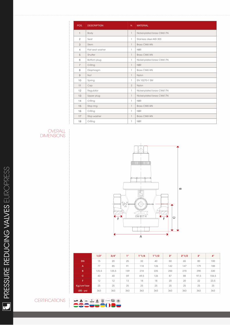
POS. DESCRIPtION N. mAtERIAl
1 Body 1 Nickel-plated brass CW617N
2 Seat 1 Stainless steel AISI 303
3 Stem 1 Brass CW614N
4 Flat seat washer 1 NBR
5 Shutter 1 Brass CW614N
6 Bottom plug 1 Nickel-plated brass CW617N
7 O-Ring 1 NBR
8 Diaphragm 1 Brass CW614N
9 Nut 1 Nylon
10 Spring 1 EN 10270-1 SM
11 Cap 2 Nylon
12 Regulator 1 Nickel-plated brass CW617N
13 Upper plug 1 Nickel-plated brass CW617N
14 O-Ring 1 NBR
15 O-Ring 1 NBR
EUR
OPR
ESS
MATERIALSFROM 1”1/4 TO 4”
PRES
SURE
RED
UC
ING
VA
LVES
EUR
OPR
ESS
OVERALLDIMENSIONS
CERTIFICATIONS
POS. DESCRIPtION N. mAtERIAl
1 Body 1 Nickel-plated brass CW617N
2 Seat 1 Stainless steel AISI 303
3 Stem 1 Brass CW614N
4 Flat seat washer 1 NBR
5 Shutter 1 Brass CW614N
6 Bottom plug 1 Nickel-plated brass CW617N
7 O-Ring 1 NBR
8 Diaphragm 1 Brass CW614N
9 Nut 1 Nylon
10 Spring 1 EN 10270-1 SM
11 Cap 2 Nylon
12 Regulator 1 Nickel-plated brass CW617N
13 Upper plug 1 Nickel-plated brass CW617N
14 O-Ring 1 NBR
15 Stop ring 1 Brass CW614N
16 O-Ring 1 NBR
17 Stop washer 1 Brass CW614N
18 O-Ring 1 NBR
B
A
CFF
1/2” 3/4” 1” 1”1/4 1”1/2 2” 2”1/2 3” 4”
DN 15 20 25 32 40 50 65 80 100
A 77 85 91 118 126 142 147 179 188
B 125,5 125,5 159 218 225 250 270 290 330
C 40 40 59 69,5 126 87 88 97,5 104,5
F 12 12 13 18 18 20 20 22 23,5
Kg/cm2 bar 25 25 25 25 25 25 25 25 25
LBS - psi 363 363 363 363 363 363 363 363 363
TEC
EUR
OPR
ESS
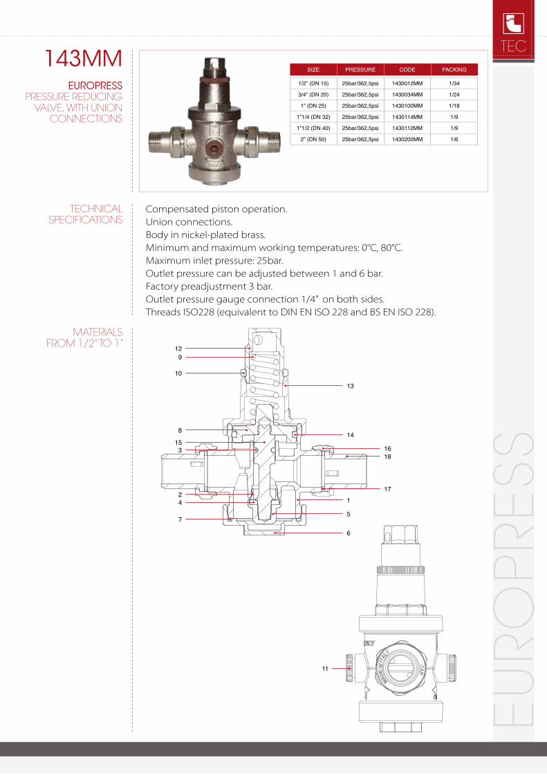
143MMEUROPRESS
PRESSURE REDUCING VALVE, WITh UNION
CONNECTIONS
MATERIALSFROM 1/2” TO 1”
Compensated piston operation.Union connections.Body in nickel-plated brass.Minimum and maximum working temperatures: 0°C, 80°C.Maximum inlet pressure: 25bar.Outlet pressure can be adjusted between 1 and 6 bar.Factory preadjustment 3 bar.Outlet pressure gauge connection 1/4” on both sides.Threads ISO228 (equivalent to DIN EN ISO 228 and BS EN ISO 228).
TEChNICALSPECIFICATIONS
SIZE PRESSURE CODE PACKING
1/2” (DN 15) 25bar/362,5psi 1430012mm 1/34
3/4” (DN 20) 25bar/362,5psi 1430034mm 1/24
1” (DN 25) 25bar/362,5psi 1430100mm 1/18
1”1/4 (DN 32) 25bar/362,5psi 1430114mm 1/9
1”1/2 (DN 40) 25bar/362,5psi 1430112mm 1/9
2” (DN 50) 25bar/362,5psi 1430200mm 1/6
129
10
8
315
7
24
11
13
14
16
17
18
1
5
6
PRES
SURE
RED
UC
ING
VA
LVES
EUR
OPR
ESS
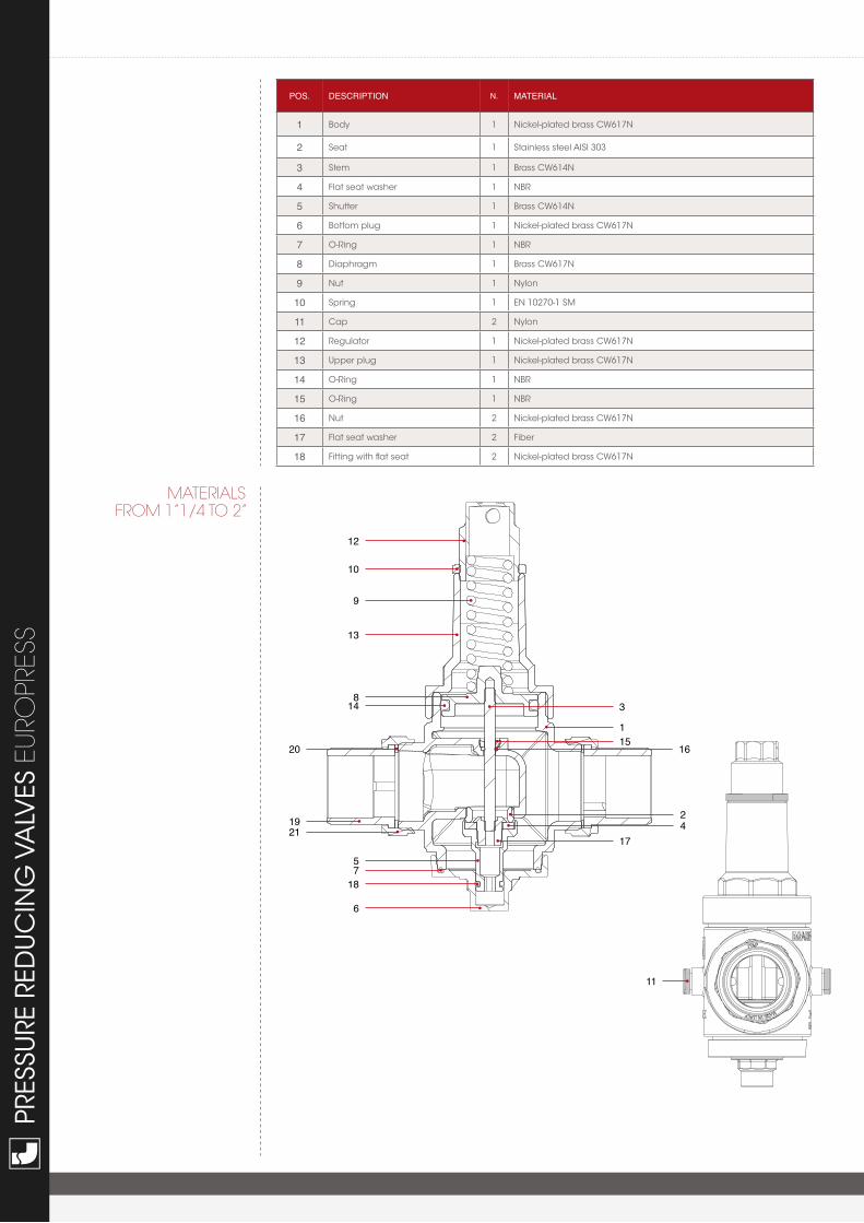
MATERIALSFROM 1”1/4 TO 2”
POS. DESCRIPtION N. mAtERIAl
1 Body 1 Nickel-plated brass CW617N
2 Seat 1 Stainless steel AISI 303
3 Stem 1 Brass CW614N
4 Flat seat washer 1 NBR
5 Shutter 1 Brass CW614N
6 Bottom plug 1 Nickel-plated brass CW617N
7 O-Ring 1 NBR
8 Diaphragm 1 Brass CW617N
9 Nut 1 Nylon
10 Spring 1 EN 10270-1 SM
11 Cap 2 Nylon
12 Regulator 1 Nickel-plated brass CW617N
13 Upper plug 1 Nickel-plated brass CW617N
14 O-Ring 1 NBR
15 O-Ring 1 NBR
16 Nut 2 Nickel-plated brass CW617N
17 Flat seat washer 2 Fiber
18 Fitting with flat seat 2 Nickel-plated brass CW617N
12
10
9
13
14
1921
20
8
57
18
6
11
3
115
1742
16
TEC
CERTIFICATIONS EUR
OPR
ESS
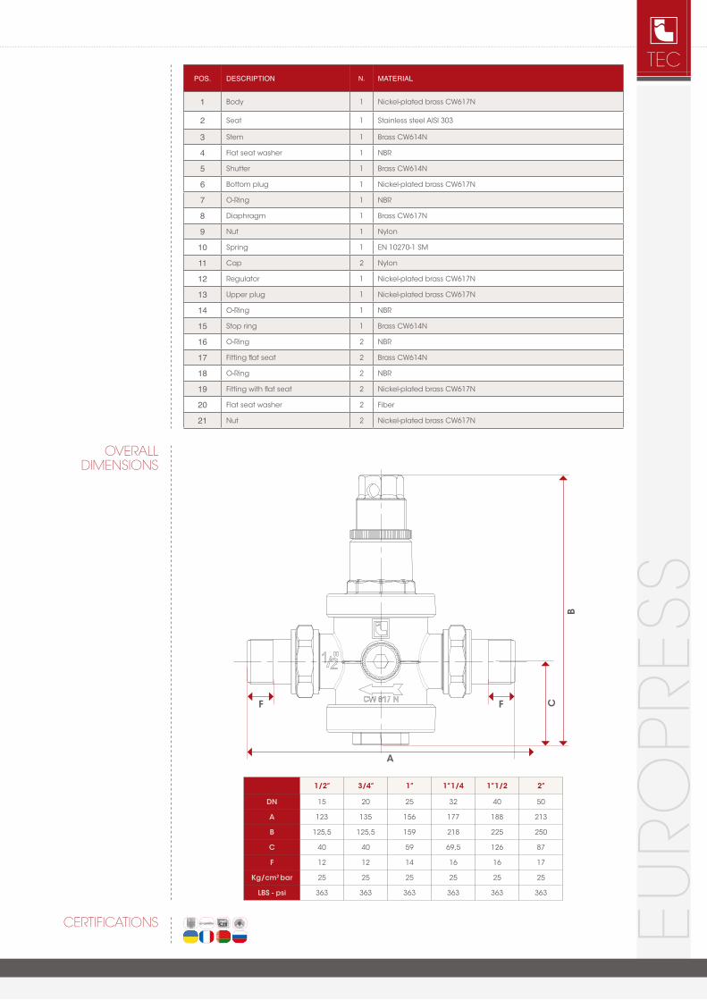
OVERALLDIMENSIONS
POS. DESCRIPtION N. mAtERIAl
1 Body 1 Nickel-plated brass CW617N
2 Seat 1 Stainless steel AISI 303
3 Stem 1 Brass CW614N
4 Flat seat washer 1 NBR
5 Shutter 1 Brass CW614N
6 Bottom plug 1 Nickel-plated brass CW617N
7 O-Ring 1 NBR
8 Diaphragm 1 Brass CW617N
9 Nut 1 Nylon
10 Spring 1 EN 10270-1 SM
11 Cap 2 Nylon
12 Regulator 1 Nickel-plated brass CW617N
13 Upper plug 1 Nickel-plated brass CW617N
14 O-Ring 1 NBR
15 Stop ring 1 Brass CW614N
16 O-Ring 2 NBR
17 Fitting flat seat 2 Brass CW614N
18 O-Ring 2 NBR
19 Fitting with flat seat 2 Nickel-plated brass CW617N
20 Flat seat washer 2 Fiber
21 Nut 2 Nickel-plated brass CW617N
B
A
CFF
1/2” 3/4” 1” 1”1/4 1”1/2 2”
DN 15 20 25 32 40 50
A 123 135 156 177 188 213
B 125,5 125,5 159 218 225 250
C 40 40 59 69,5 126 87
F 12 12 14 16 16 17
Kg/cm2 bar 25 25 25 25 25 25
LBS - psi 363 363 363 363 363 363
PRES
SURE
RED
UC
ING
VA
LVES
EUR
OPR
ESS
1 2 3 4 5 6 7 8 9 10 20 30 40 50 70 100 200
1/2”
3/4”
1”
1 1/
4”1
1/2”
2” 3” 4”2 1/
2”
300
400
500
700
1000
2000
0.4
0.5
0.6
0.7
0.8
0.9
1.5
1
Pres
sure
dro
p [B
ar]
Flow rate [l/min]
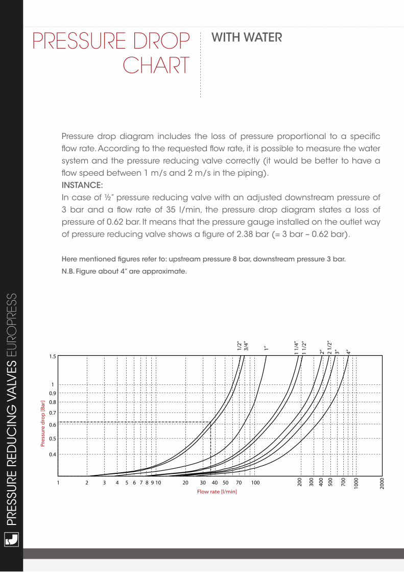
PRESSURE DROP ChART
With Water
Pressure drop diagram includes the loss of pressure proportional to a specific flow rate. According to the requested flow rate, it is possible to measure the water system and the pressure reducing valve correctly (it would be better to have a flow speed between 1 m/s and 2 m/s in the piping).iNStaNCe:In case of ½” pressure reducing valve with an adjusted downstream pressure of 3 bar and a flow rate of 35 l/min, the pressure drop diagram states a loss of pressure of 0.62 bar. It means that the pressure gauge installed on the outlet way of pressure reducing valve shows a figure of 2.38 bar (= 3 bar – 0.62 bar).
here mentioned figures refer to: upstream pressure 8 bar, downstream pressure 3 bar.
N.B. Figure about 4” are approximate.
TEC
EUR
OPR
ESS
MANIFACTURERINSTRUCTIONS
installation For the best use and duration of the system, it is necessary to comply with the following instructions on installation, with the national regulations and with relevant local requirements.- Place of installation has to be protected from frost and has to be easily inspectable- Install the pressure reducing valve on the private water system, immediately downstream of the water meter- It would be better to install shut-off valves upstream and downstream of the pressure reducing valve, to facilitate the maintenance operations- In order to protect pressure reducing valve from overpressure, install a check valve immediately downstream of the pressure reducing valve- The right scheme of installation is shown in Fig. 5.2 - In case of water heater downstream of the pressure reducing valve, install an expansion vessel between the valve and the water heater - In order to avoid cavitation and therefore excessive noiseness, it is strongly recommended that the ratio between maximum upstream pressure and regulating downstream pressure does not exceed the value of 2,5.- Pressure reducing valve is not a safety device. It would be better to install all the necessary safety relief valves.Please, duly note the downstream pressure of the reducing valve has not to be higher than the maximum working pressure of the devices installed in the private water system, in order to avoid possible damages or malfunctions.
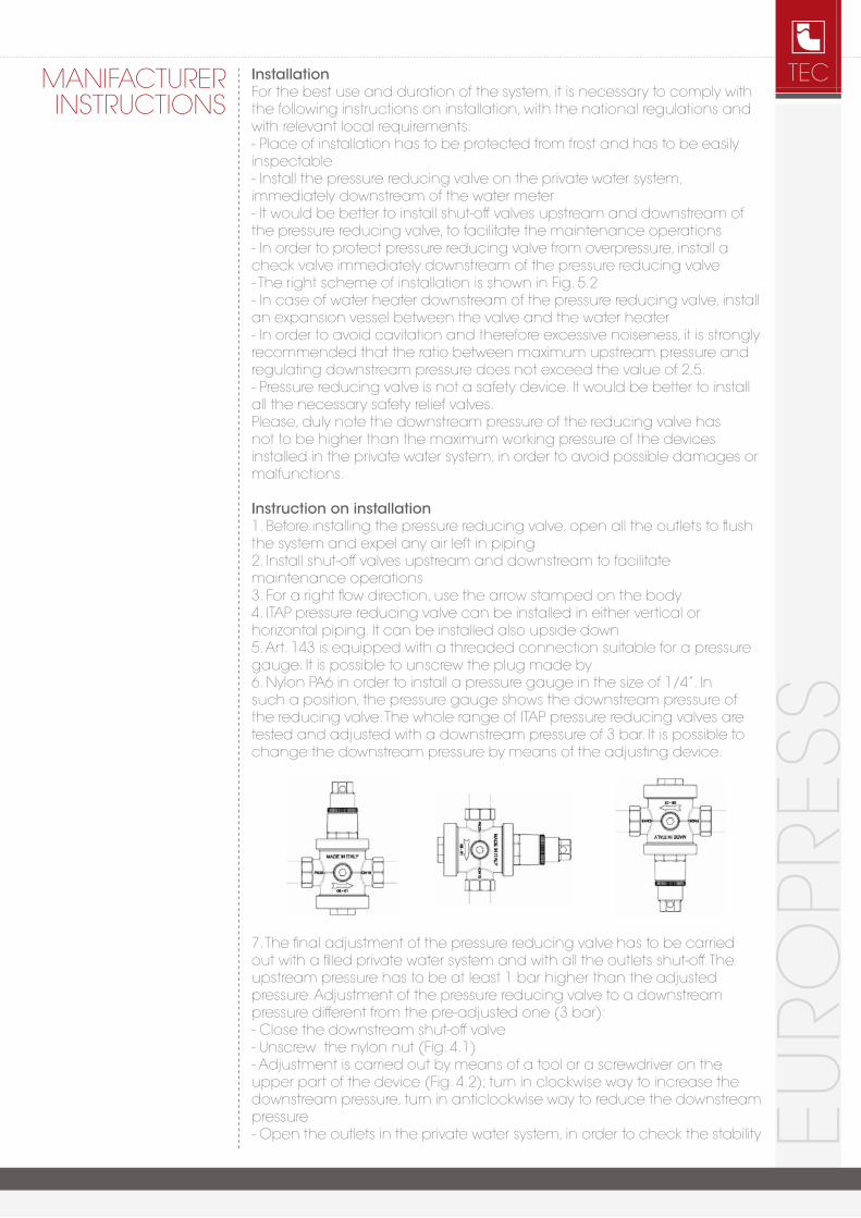
instruction on installation1. Before installing the pressure reducing valve, open all the outlets to flush the system and expel any air left in piping2. Install shut-off valves upstream and downstream to facilitate maintenance operations3. For a right flow direction, use the arrow stamped on the body4. ITAP pressure reducing valve can be installed in either vertical or horizontal piping. It can be installed also upside down5. Art. 143 is equipped with a threaded connection suitable for a pressure gauge. It is possible to unscrew the plug made by 6. Nylon PA6 in order to install a pressure gauge in the size of 1/4”. In such a position, the pressure gauge shows the downstream pressure of the reducing valve. The whole range of ITAP pressure reducing valves are tested and adjusted with a downstream pressure of 3 bar. It is possible to change the downstream pressure by means of the adjusting device.
7. The final adjustment of the pressure reducing valve has to be carried out with a filled private water system and with all the outlets shut-off. The upstream pressure has to be at least 1 bar higher than the adjusted pressure. Adjustment of the pressure reducing valve to a downstream pressure different from the pre-adjusted one (3 bar):- Close the downstream shut-off valve- Unscrew the nylon nut (Fig. 4.1)- Adjustment is carried out by means of a tool or a screwdriver on the upper part of the device (Fig. 4.2); turn in clockwise way to increase the downstream pressure, turn in anticlockwise way to reduce the downstream pressure- Open the outlets in the private water system, in order to check the stability
PRES
SURE
RED
UC
ING
VA
LVES
EUR
OPR
ESS
MANIFACTURERINSTRUCTIONS
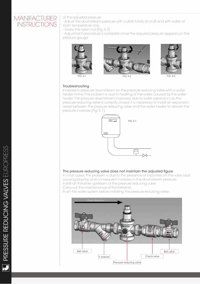
of the adjusted pressure- Adjust the downstream pressure with outlets totally shut-off and with water at room temperature only- Screw the nylon nut (Fig. 4.3)- Adjustment procedure is complete once the required pressure appears on the pressure gauge.
troubleshootingIncrease in pressure downstream on the pressure reducing valve with a water heater in-line. This problem is due to heating of the water, caused by the water heater. The pressure downstream increases, due to water expansion, as the pressure reducing valve is correctly closed. It is necessary to install an expansion vessel between the pressure reducing valve and the water heater to absorb the pressure increase (Fig. 5.1).
the pressure reducing valve does not maintain the adjusted figureIn most cases, this problem is due to the presence of impurities on the valve seat, causing blow-by and consequent increase in the downstream pressure.Install an Y-strainer upstream of the pressure reducing valve.Carry-out the maintenance of the Y-strainer.Flush the water system before installing the pressure reducing valve.
FIG. 4.1 FIG. 4.2 FIG. 4.3
FIG. 5.1
Ball valve Ball valve
Check valveY strainer
Flow direction
Pressure reducing valve
TEC
EUR
OPR
ESS
We reserve the right to make improvements and changes to the products described herein and to the relative technical data, at any time and without forewarning.
NOTES

ITAP S.p.A.Via Ruca 1925065 LumezzaneBrescia (ITALIA)Tel 030 89270Fax 030 [email protected] 07
/201
4