Embed Size (px)
Citation preview
Current sensorsVoltage sensors
Technical catalog
Contact John G Peck Ltd - jgpl.com

Contact John G Peck Ltd - jgpl.com
ABB Current sensors / Voltage sensors | 1
Technologies
Current measuring technology 4
Voltage measuring technology 8
Voltage detection technology 10
Glossary 12
Industry current sensors
Panorama of industry current sensors 14
NCS type current sensors 20
HBO type current sensors 40
ES type current sensors 46
TYA type current sensors 52
MP/EL type current sensors 56
Substation and traction current sensors
Panorama of substation and traction current sensors 58
NCS type current sensors 62
CS type current sensors 76
TYA type current sensors 84
Traction voltage sensors
Panorama of voltage sensors 88
VS type voltage sensors 90
EM type voltage sensors 96
Traction voltage detectors
VD type voltage detectors 100
Common information for industry and traction sensors
Instructions for mounting and wiring 104
Questionnaire product selection guide 114
Calculation guide for closed loop Hall effect current sensors 120
Calculation guide for electronic technology current sensors 123
Calculation guide for electronic technology voltage sensors 124
Our distributors 126
Index 128
Current sensorsVoltage sensors
Contact John G Peck Ltd - jgpl.com

2 | ABB Current sensors / Voltage sensors
Contact John G Peck Ltd - jgpl.com

ABB Current sensors / Voltage sensors | 3
Because you search for performance we make the difference.
In the industrial and railway sectors, where the tendency for all players is towards higher performance, ABB current and voltage sensors provide competitive and adapted solutions. To meet your requirements, they draw on all their qualities to give you the advantage.Resulting from a totally electronic technology, they integrate the latest innovations. More compact, they allow for the optimum reduction in equipment dimensions. Made from high technology material, ABB sensors offer exceptional thermal performance, a stronger mechanical robustness and gener-ally excellent resistance to harsh external conditions. These products conform to ecological, security and strict quality standards.
Contact John G Peck Ltd - jgpl.com

4 | ABB Current sensors / Voltage sensors
Three technologies for measuring current
The secondary output current IS is there-fore exactly proportional to the primary current at any moment. It is an exact replica of the primary current multiplied by the number of turns NP/NS. This secondary current IS can be passed through a measuring resistance RM. The measuring voltage VM at the ter-minals of this measuring resistance RM is therefore also exactly proportional to the primary current IP.
PrincipleABB current sensors based on closed loop Hall effect technology are electronic trans-formers. They allow for the measurement of direct, alternating and impulse currents, with galvanic insulation between the primary and secondary circuits.The primary current IP flowing across the sensor creates a primary magnetic flux.The magnetic circuit channels this magnetic flux. The Hall probe placed in the air gap of the magnetic circuit provides a voltage proportional to this flux. The electronic circuit amplifies this voltage and converts it into a secondary cur-rent IS. This secondary current multiplied by the number of turns Ns of secondary winding cancels out the primary magnetic flux that created it (contra reaction). The formula NP x IP = NS x IS is true at any time. The current sensor measures instanta-neous values.
Advantages Applications
Industry Traction
1. Closed loop Hall effect technology
M
+
_
+ VA
_ VA
IS
IP
NP
NS
0V
Power supplySensor
RM
VM
G10
8DG
The main advantages of this closed loop Hall effect technology are as follows: – Galvanic insulation between the
primary and secondary circuits – Measurement of all waveforms is
possible: direct current, alternating current, impulse, etc.
– High accuracy over a large frequency range (from direct to more than 100 kHz)
– High dynamic performance – High overload capacities – High reliability.
Variable speed drives, Uninterruptible Power Suppliers (UPS), active harmonic filters, battery chargers, wind genera-tors, robotics, conveyers, lifts, cranes, solar inverter, elevator, etc.
Main converters, auxiliary converters (lighting, air conditioning), battery char-gers, choppers, substations, mining, etc.
Contact John G Peck Ltd - jgpl.com

Tech
nolo
gie
s
ABB Current sensors / Voltage sensors | 5
Advantages Applications
Industry
The secondary output voltage VS is therefore directly proportional to the primary current. It is an exact replica of the primary current, generally with a value of 4 V for a nominal current IPN.
PrincipleABB current sensors based on open loop Hall effect technology are also electronic transformers. They allow for the measurement of direct, alternating and impulse currents, with galvanic insulation between the primary and secondary circuits.The primary current IP flowing across the sensor creates a primary magnetic flux.The magnetic circuit channels this magnetic flux. The Hall probe placed in the air gap of the magnetic circuit provides a voltage VH proportional to this flux, which is itself proportional to the current IP to be measured.The electronic circuit amplifies this Hall voltage (VH) allowing it to be directly exploited by the operator as a secondary output voltage VS.The current sensor measures instantaneous values.
2. Open loop Hall effect technology
VM
RM VS
+ VA
_ VA
+ VA
_ VA
IP
0V
Power supplySensor
G02
12D
G
0V
The main advantages of this open loop Hall effect technology are as follows: – Galvanic insulation between the pri-
mary and secondary circuits. – Measurement of all waveforms is
possible: direct current, alternating current, impulse, etc.
Variable speed drives, backups ("UPS"), active harmonic filters, battery chargers, conveyers, lifts, cranes, solar inverter, etc.
– Good accuracy over a medium fre-quency range (from direct to several tens of kHz).
– High reliability. – Low power consumption. – Reduced weight and volume. – Excellent Performance/Cost ratio.
Contact John G Peck Ltd - jgpl.com

6 | ABB Current sensors / Voltage sensors
PrincipleABB current sensors are based on entirely electronic technology. In contrast to closed or open loop Hall effect technology, no magnetic circuit is used in the sensor.They allow for the measurement of direct, alternating and impulse currents with galvanic insulation between the primary and secondary circuits.The primary current IP flowing across the sensor creates a primary magnetic flux. The different Hall probes included in the sensor measure this magnetic flux. The electronic circuit conditions and treats these signals (summation and amplification) to provide two output currents IS1 and IS2 and/or two output voltages VS1 and VS2. All the outputs are exactly proportional to the measured primary current. The current sensor measures instantaneous values.
3. Electronic technology
RM
0V
VM
Power supplySensor
G02
15D
G
IP
IS
VS
_ _ VA
0V
0V 0V
+ + VA
IS RM
VM
Σ
U I
The main advantages of this electronic technology are as follows: – Galvanic insulation between the pri-
mary and secondary circuits – Measurement of all waveforms is
possible: direct current, alternating current, impulse, etc.
– Choice of output type (current or volt-age, IPN or IPMAX)
– Very large current measuring range (up to 40 kA) without overheating the sensor
– High dynamic performance – Low power consumption – Reduced weight and volume – Simplified mechanical fixing.
Three technologies for measuring current
Advantages Applications
Industry Substation
Electrolysis, rectifiers, welding, etc. Substations in continuous voltage.
Contact John G Peck Ltd - jgpl.com

Tech
nolo
gie
s
ABB Current sensors / Voltage sensors | 7
2000 A100 A
40 kA4 kA
Electronic technology
Electronic technology
Product ranges for current measurement
500 A300 A
100 A5 A
600 A100 A
40 kA4 kA
2000 A
500 A
300 A
300 A
Industry applications
Railway applications
Substation applications
Closed loop Hall effect technology
Closed loop Hall effect technology
Open loop Hall effect technology
Range Accuracy Frequency Consumption
ES
TYA
MP-EL
Range Accuracy Frequency Consumption
CS
TYA
Range Accuracy Frequency Consumption
HBO
Range Accuracy Frequency Consumption
NCS
Range Accuracy Frequency Consumption
NCS
Fixed application only
Contact John G Peck Ltd - jgpl.com

8 | ABB Current sensors / Voltage sensors
Two technologies for measuring voltage
PrincipleABB voltage sensors based on closed loop Hall effect technology are also electron-ic transformers. They allow for the measurement of direct, alternating and impulse voltages with galvanic insulation between the primary and secondary circuits.The primary voltage UP to be measured is applied directly to the sensor terminals: HT+ (positive high voltage) and HT– (negative high voltage). An input resistance RE must necessarily be placed in series with the resistance RP of the primary winding to limit the current IP and therefore the heat dissipated from the sensor. This resistance RE may be either integrated during the manufacturing of the product (calibrated sen-sor) or added externally by the user to determine the voltage rating (not calibrated sensor).The primary current IP flowing across the primary winding via this resistance RE generates a primary magnetic flux. The magnetic circuit channels this magnetic flux. The Hall probe placed in the air gap of the magnetic circuit provides a voltage VH proportional to this flux.The electronic circuit amplifies this voltage and converts it into a secondary current IS. This secondary current multiplied by the number of turns NS of secondary wind-ing cancels out the primary magnetic flux that created it (contra reaction). The formula NP x IP = NS x IS is true at any time.The voltage sensor measures instantaneous values.The secondary output current IS is therefore exactly proportional to the primary voltage at any moment. It is an exact replica of the primary voltage. This secondary current IS is passed through a measuring resistance RM. The measuring voltage VM at the terminals of this measuring resistance RM is therefore also exactly propor-tional to the primary voltage UP .
Advantages ApplicationsThe main advantages of this closed loop Hall effect technology are as follows: – Galvanic insulation between the pri-
mary and secondary circuits. – Measurement of all waveforms is
possible: direct voltage, alternating voltage, impulse, etc.
– High accuracy. – High reliability.
RM M
+
_
+ VA
_ VA
IS
NP
NS
0V
Power supply Sensor
G02
13D
G
IP
UP
HT+
HT-
RE
VM
Principle diagram of a not calibrated EM010 sensor
Principle diagram of a calibrated EM010 sensor
RM M
+
_
+ VA
_ VA
IS
NP
NS
0V
Power supplySensor
G02
14D
G
IP
UP
HT+
HT-
VM
RE
1. Closed loop Hall effect technology
Traction
Main converters, auxiliary converters (lighting, air conditioning), battery char-gers, choppers, substations, mining, etc.
Contact John G Peck Ltd - jgpl.com

Tech
nolo
gie
s
ABB Current sensors / Voltage sensors | 9
HT ++
M
+ VA
0 V
– VA–
RM
HT -
Power supply Sensor
G15
5DG
UpIs
VM
In the same way as for current sensors, this secondary current Is can be then passed through a measuring resistance Rm. The measuring voltage Vm at the terminals of this measuring resistance Rm is therefore also exactly proportional to the primary voltage Up. The electrical supply to the sensor is also insulated from the primary voltage.
PrincipleABB voltage sensors based on electronic technology only use electronic com-ponents. In contrast to closed or open loop Hall effect technology, no magnetic circuits or Hall effect probes are used in the sensor.This allows for the measurement of direct or alternating voltages with electrical insu-lation between the primary and secondary circuits.The primary voltage to be measured is applied directly to the sensor terminals: HT+ (positive high voltage) and HT– (negative high voltage or earth). This voltage is passed through an insulating amplifier and is then converted to a secondary output current IS. This secondary current Is is electrically insulated from the primary voltage to which it is exactly proportional. The voltage sensor measures instantaneous values.
Advantages ApplicationsThe main advantages of this fully elec-tronic technology are as follows: – Electrical insulation between the
primary and secondary circuits. – Measurement of all waveforms is
possible: direct voltage, alternating voltage, impulse, etc.
Traction
2. Electronic technology
Main converters, auxiliary converters (lighting, air conditioning), battery char-gers, choppers, substations, mining, etc.
– Excellent immunity to electromag-netic fields.
– Excellent accuracy. – High dynamic performance. – Excellent reliability.
Contact John G Peck Ltd - jgpl.com

10 | ABB Current sensors / Voltage sensors
G02
16D
G
UP
HT1+
HT1-
UP
HT2+
HT2-
Detector
PCB
UP+
UP-
PCB
The voltage detector indicates the presence of a voltage higher than a limit (maximum 50V in compliance with standards) by the illumination of a LED. Inversely, the LED is extin-guished when the voltage is below this limit.
PrincipleABB voltage detector is based on entirely electronic technology. It allows the de-tection of the presence of direct voltages. For safety reasons this main function is duplicated within the detector to increase the product lifetime.The voltage detector converts the primary voltage UP applied to its terminals to vi-sual information for the user. This function permits the user to carryout maintenance operations with the assurance that dangerous voltage is not present.The primary voltage UP to be measured is applied directly to the detector terminals: HT1+ and HT2+ (positive high voltage) and HT1– and HT2- (negative high voltage or 0 V electric). The electronic circuit (PCB) converts the primary voltage UP to an electrical signal supplied to a light emitting diode (LED).The information is supplied to the user visually through two flashing LEDs. The detector does not need an external power supply in order to work.
ApplicationsAdvantagesThe main advantages of this electronic technology are as follows: – Detection of direct voltages. – Very good visual indication. – High overload capacities.
Voltage detection technology
1. Electronic technology
Traction
Main converters, auxiliary converters (lighting, air conditioning), electronic power devices integrating capacitors banks, battery chargers, choppers, substations, etc.
– Excellent reliability (functional redun-dancy in a single product).
– Excellent immunity to magnetic fields. – Compact product.
Contact John G Peck Ltd - jgpl.com

Tech
nolo
gie
s
ABB Current sensors / Voltage sensors | 11
5000 V600 V
Product ranges
For voltage measurement
For voltage detection
4200 V50 V
1500 V50 V
Railway applications
Railway applications
Closed loop Hall effect technology
Range Accuracy Frequency Standards
EM010
Range Accuracy Frequency Standards
VS
Range Reliability Standards
VD
Electronic technology
Electronic technology
Contact John G Peck Ltd - jgpl.com

12 | ABB Current sensors / Voltage sensors
GlossaryDescription of the main current and voltage sensor's characteristics
Nominal primary current (IPN) and nominal primary voltage (UPN)This is the maximum current or voltage that the sensor can continuously withstand (i.e. without time limit).
The sensor is thermally sized to continuously withstand this value.
For alternating currents, this is the r.m.s. value of the sinusoidal current.
The value given in the catalogue or in the technical data sheet is a nominal rating value. This figure can be higher if certain conditions (temperature, supply voltage…) are less restricting.
- Supply voltage:The measuring range increases with the supply voltage.
- Measuring resistance:The measuring range increases when the measuring
resistance is reduced.
Not measurable overloadThis is the maximum instantaneous current or voltage that the sensor can
withstand without being destroyed or damaged.
However the sensor is not able to measure this overload value.
This value must be limited in amplitude and duration in order to avoid magnetising the magnetic circuit, overheating or straining the electronic components. A sensor can withstand a lower value overload for longer.
G02
08D
G
IPmax or UPmax
VA
G02
09D
G
IPmax or UPmax
RM
G02
10D
G
IPN or UPN
Not measurable overload
Time
Measuring range (IPMAX and UPMAX)This is the maximum current or voltage that the sensor can measure with the Hall effect. In general, mainly for thermal reasons, the sensor cannot continuously measure this value for direct currents and voltages.
This measuring range is given for specific operating conditions. This can vary depending mainly on the parameters below (see calculation ex-amples p. 120 and onwards):
Operating range (IPN, UPN) and temperature (°C)The sensor has been designed for a certain operating temperature. If this temperature is reduced, then it is possible to use the sensor with a higher thermal current or voltage.
G02
49D
G
IPN or UPN
T°C
Contact John G Peck Ltd - jgpl.com
Tech
nolo
gie
s
ABB Current sensors / Voltage sensors | 13
Secondary current ISN at IPN or at UPN
This is the sensor's output current IS when the input is equal to the nominal primary current IPN or to the nominal primary voltage UPN.
Measuring resistance RM
This is the resistance connected in the secondary measuring circuit between terminal M of the current or voltage sensor and the 0 V of the supply.
The measuring voltage VM at the terminals of this resistance RM is proportional to the sensor's secondary current IS.
It is therefore the image of the sensor's primary current IP or primary voltage UP.
For thermal reasons, a minimum value is sometimes required in certain operating conditions in order to limit overheating of the sensor.
The maximum value for this resistance is determined by the measuring range.
(see calculation examples p. 120 and onwards and the curve IPMAX or UPMAX = f(RM) opposite).
AccuracyThis is the maximum error for the sensor output ISN for the nominal input value (current or voltage).
This takes into account the residual current, linearity and thermal drift.
AC accuracy This is the maximum error for the sensor's output ISN for an alternating sinusoidal primary current with a frequency of 50 Hz.
The residual current is not taken into account. The linearity and thermal drift are always included.
No-load consumption current This is the sensor's current consumption when the primary current (or primary voltage) is zero.
The total current consumption of the sensor is therefore the no-load consumption current plus the secondary current.
All given performance and data included in this catalogue could change.Dedicated data sheets are the only recognized reference documents
for the given performances and data. To have the datasheets, please contact your local distributor (see page 126-127).
GlossaryDescription of the main current and voltage sensor's characteristics
Contact John G Peck Ltd - jgpl.com

14 | ABB Current sensors / Voltage sensors
These sensors are designed to be fixed by the case.They may be either vertically or horizontally mounted.The secondary connection is made with a connector or cable.For NCS sensors the primary conductor may be a cable, one or several bars.
Frame mounting
Panorama of industry current sensors
Nominalprimary current
Opening forthe primaryconductor
Secondarycurrent IS1
at ±IPN
Secondaryvoltage VS1
at ±IPN
Supplyvoltage
Secondary connection
Type Order code
A peak mm mA peak V peak V DC4000 125 ±20 ±10 ±15 … ±24 Straight connector
8 pinNCS125-4 1SBT200204R0001
4000 125 ±20 – ±15 … ±24 Shielded cable 6 wires (2m)
NCS125-4AF 1SBT200204R0002
4000 125 – ±10 ±15 … ±24 Shielded cable 6 wires (2m)
NCS125-4VF 1SBT200204R0102
4000 165 ±20 ±10 ±15 … ±24 Straight connector 8 pin
NCS165-4 1SBT200604R0001
4000 165 ±20 – ±15 … ±24 Shielded cable 6 wires (2m)
NCS165-4AF 1SBT200604R0002
4000 165 – ±10 ±15 … ±24 Shielded cable 6 wires (2m)
NCS165-4VF 1SBT200604R0102
6000 125 ±20 ±10 ±15 … ±24 Straight connector 8 pin
NCS125-6 1SBT200206R0001
6000 125 ±20 – ±15 … ±24 Shielded cable 6 wires (2m)
NCS125-6AF 1SBT200206R0002
6000 125 – ±10 ±15 … ±24 Shielded cable 6 wires (2m)
NCS125-6VF 1SBT200206R0102
6000 165 ±20 ±10 ±15 … ±24 Straight connector 8 pin
NCS165-6 1SBT200606R0001
6000 165 ±20 – ±15 … ±24 Shielded cable 6 wires (2m)
NCS165-6AF 1SBT200606R0002
6000 165 – ±10 ±15 … ±24 Shielded cable 6 wires (2m)
NCS165-6VF 1SBT200606R0102
10000 125 ±20 ±10 ±15 … ±24 Straight connector 8 pin
NCS125-10 1SBT200210R0001
10000 125 ±20 – ±15 … ±24 Shielded cable 6 wires (2m)
NCS125-10AF 1SBT200210R0002
10000 125 – ±10 ±15 … ±24 Shielded cable 6 wires (2m)
NCS125-10VF 1SBT200210R0102
10000 165 ±20 ±10 ±15 … ±24 Straight connector 8 pin
NCS165-10 1SBT200610R0001
10000 165 ±20 – ±15 … ±24 Shielded cable 6 wires (2m)
NCS165-10AF 1SBT200610R0002
10000 165 – ±10 ±15 … ±24 Shielded cable 6 wires (2m)
NCS165-10VF 1SBT200610R0102
20000 165 ±20 ±10 ±15 … ±24 Straight connector 8 pin
NCS165-20 1SBT200620R0001
20000 165 ±20 – ±15 … ±24 Shielded cable 6 wires (2m)
NCS165-20AF 1SBT200620R0002
20000 165 – ±10 ±15 … ±24 Shielded cable 6 wires (2m)
NCS165-20VF 1SBT200620R0102
NCS125-4 to NCS125-10
1SB
C14
6008
F001
4
NCS165-4 to NCS165-20
1SB
C14
6009
F001
4
NCS125-4AF to NCS125-10AFNCS125-4VF to NCS125-10VF
1SB
C14
6017
F001
4
NCS165-4AF to NCS165-20AFNCS165-4VF to NCS165-20VF
1SB
C14
6018
F001
4
Contact John G Peck Ltd - jgpl.com

Ind
ustr
y se
nso
rs
ABB Current sensors / Voltage sensors | 15
HBO100 to HBO600
These sensors are designed to be fixed by the case.They may be either vertically or horizontally mounted.The secondary connection is made with a connector.For HBO sensors the primary conductor may be a cable or a bar.
Frame mounting
Panorama of industry current sensors
NCS305-6 to NCS305-20
NCS305-6AF to NCS305-20AFNCS305-6VF to NCS305-20VF
Nominalprimary current
Opening forthe primaryconductor
Secondarycurrent IS1
at ±IPN
Secondaryvoltage VS1
at ±IPN
Supplyvoltage
Secondary connection Type Order code
A peak mm mA peak V peak V DC6 302 ±20 ±10 +15 … +24
(±2%)Straight connector 8 pin NCS305-6 1SBT200306R0001
6 302 ±20 – +15 … +24 (±2%)
Shielded cable 6 wires (2m) NCS305-6AF 1SBT200306R0002
6 302 – ±10 +15 … +24 (±2%)
Shielded cable 6 wires (2m) NCS305-6VF 1SBT200306R0102
10 302 ±20 ±10 +15 … +24 (±2%)
Straight connector 8 pin NCS305-10 1SBT200310R0001
10 302 ±20 – +15 … +24 (±2%)
Shielded cable 6 wires (2m) NCS305-10AF 1SBT200310R0002
10 302 – ±10 +15 … +24 (±2%)
Shielded cable 6 wires (2m) NCS305-10VF 1SBT200310R0102
20 302 ±20 ±10 +15 … +24 (±2%)
Straight connector 8 pin NCS305-20 1SBT200320R0001
20 302 ±20 – +15 … +24 (±2%)
Shielded cable 6 wires (2m) NCS305-20AF 1SBT200320R0002
20 302 – ±10 +15 … +24 (±2%)
Shielded cable 6 wires (2m) NCS305-20VF 1SBT200320R0102
Nominalprimary current
Secondaryvoltageat IPN
Supplyvoltage
Secondary connection Type Order code
A r.m.s. V V DC100 ±4 ±12 … ±15 Molex type 4 pin HBO100 1SBT210100R0001
200 ±4 ±12 … ±15 Molex type 4 pin HBO200 1SBT210200R0001
300 ±4 ±12 … ±15 Molex type 4 pin HBO300 1SBT210300R0001
400 ±4 ±12 … ±15 Molex type 4 pin HBO400 1SBT210400R0001
500 ±4 ±12 … ±15 Molex type 4 pin HBO500 1SBT210500R0001
600 ±4 ±12 … ±15 Molex type 4 pin HBO600 1SBT210600R0001
NC
S30
5N
CS
305b
1SB
C79
1293
F030
2
Contact John G Peck Ltd - jgpl.com

16 | ABB Current sensors / Voltage sensors
These sensors are designed to be fixed by the case.They may be either horizontally or vertically mounted.The secondary connection is made with a connector or cable.For ES and ESM sensors the primary conductor may be a cable or a bar.
Frame mounting
ES100C
ES300C
ES500C
ES1000C
ES2000C
ESM1000C
Panorama of industry current sensors1S
BC
7897
94F0
302
1SB
C78
9824
F030
21S
BC
7898
34F0
302
1SB
C78
9804
F030
2
1SB
C78
9814
F030
2
1SB
C78
9844
F030
2
Nominalprimary current
Secondarycurrentat IPN
Supplyvoltage
Secondary connection Type Order code
A r.m.s. mA V DC100 100 ±12 … ±24 Molex type 3 pins HE 14 ES100C 1SBT150100R0001
100 100 ±12 … ±24 3 wires 200 mm ES100F 1SBT150100R0002
300 150 ±12 … ±24 Molex type 3 pins HE 14 ES300C 1SBT150300R0001
300 150 ±12 … ±24 JST 3 pins ES300S 1SBT150300R0003
300 150 ±12 … ±24 3 wires 200 mm ES300F 1SBT150300R0002
500 100 ±12 … ±24 Molex type 3 pins HE 14 ES500C 1SBT150500R0001
500 100 ±12 … ±24 JST 3 pins ES500S 1SBT150500R0003
500 100 ±12 … ±24 3 wires 200 mm ES500F 1SBT150500R0002
500 125 ±12 … ±24 Molex type 3 pins HE 14 ES500-9672 1SBT150500R9672
500 125 ±12 … ±24 JST 3 pins ES500-9673 1SBT150500R9673
500 125 ±12 … ±24 3 wires 200 mm ES500-9674 1SBT150500R9674
1000 200 ±12 … ±24 Molex type 3 pins HE 14 ES1000C 1SBT151000R0001
1000 200 ±12 … ±24 JST 3 pins ES1000S 1SBT151000R0003
1000 200 ±12 … ±24 3 wires 200 mm ES1000F 1SBT151000R0002
1000 250 ±12 … ±24 Molex type 3 pins HE 14 ES1000-9678 1SBT151000R9678
1000 250 ±12 … ±24 JST 3 pins ES1000-9679 1SBT151000R9679
1000 250 ±12 … ±24 3 wires 200 mm ES1000-9680 1SBT151000R9680
1000 200 ±15 … ±24 Molex type 3 pins HE 14 ESM1000C 1SBT191000R0003
1000 200 ±15 … ±24 JST 3 pins ESM1000S 1SBT191000R0002
1000 200 ±15 … ±24 3 wires 200 mm ESM1000F 1SBT191000R0001
2000 400 ±15 … ±24 Molex type 3 pins HE 14 ES2000C 1SBT152000R0003
2000 400 ±15 … ±24 JST 3 pins ES2000S 1SBT152000R0002
2000 400 ±15 … ±24 3 wires 200 mm ES2000F 1SBT152000R0001
Contact John G Peck Ltd - jgpl.com

Ind
ustr
y se
nso
rs
ABB Current sensors / Voltage sensors | 17
The sensors are designed to be fixed by the case in a vertical position.The secondary connection is made with a connector molded with the case.For TYA sensors the primary conductor may be a cable or a bar (better).
Frame mounting
TYA300-1521
Panorama of industry current sensors
Nominalprimary current
Secondarycurrentat IPN
Supplyvoltage
Secondary connection Type Order code
A r.m.s. mA V DC300 150 ±15 Molex type 4 pins
022041041TYA300-1521 1SBT220300R001
300 150 ±24 Molex type 4 pins022041041
TYA300-2423 1SBT220300R0003
400 100 ±15 Molex type 4 pins022041041
TYA500-1545 1SBT220500R0005
500 125 ±24 Molex type 4 pins022041041
TYA500-2447 1SBT220500R0007
1SB
C14
6023
F000
0
Contact John G Peck Ltd - jgpl.com

18 | ABB Current sensors / Voltage sensors
MP25P1
EL25P1BB to 100P2BB
EL25P1 to 100P2
These sensors are designed for PCB mounting.The sensor is mechanically fixed by soldering the secondary circuit pins to the PCB.The primary connection can also be integrated in the sensor (pins for MP sensors, integrated primary bar for EL…BB sensors).The primary conductor for EL sensors can also be a cable or a bar.
For MP sensors the primary pin combination determines the sensor's nominal rating (see table p. 57).
PCB mounting
Panorama of industry current sensors
Nominalprimary current
Secondarycurrentat IPN
Supplyvoltage
Primary connection
Secondary connection
Type Order code
A r.m.s. mA V DC25 25 ±12 … ±15 Hole
Ø 7.5 mm3 pins EL25P1 1SBT132500R0001
25 25 ±12 … ±15 Bar 3 pins EL25P1BB 1SBT132500R0002
50 50 ±12 … ±15 HoleØ 10 mm
3 pins EL50P1 1SBT135100R0001
50 50 ±12 … ±15 Bar 3 pins EL50P1BB 1SBT135100R0003
50 25 ±12 … ±15 HoleØ 10 mm
3 pins EL55P2 1SBT135100R0002
50 25 ±12 … ±15 Bar 3 pins EL55P2BB 1SBT135100R0004
100 50 ±12 … ±15 HoleØ 10 mm
3 pins EL100P2 1SBT130100R0001
100 50 ±12 … ±15 Bar 3 pins EL100P2BB 1SBT130100R0002
* see table p. 57 "MP25P1: arrangement of primary terminals and related characteristics".
Nominalprimary current
Secondarycurrentat IPN
Supplyvoltage
Primary connection
Secondary connection
Type Order code
A r.m.s. mA V DC5 to 25* 24 or 25* ±12 … ±15 Pins 3 pins MP25P1 1SBT312500R0001
1SB
C77
1743
F030
11S
BC
1460
19F0
014
1SB
C14
6013
F001
4
Contact John G Peck Ltd - jgpl.com

Ind
ustr
y se
nso
rs
ABB Current sensors / Voltage sensors | 19
Notes
Contact John G Peck Ltd - jgpl.com

302
mm
165
mm
125
mm
20 | ABB Current sensors / Voltage sensors
The NCS125/165 sensor is entirely symmetrical. Its square shape and strategically positioned oblong holes make it easy to fasten in a choice of 2 positions.As an accessory it comes with a side plate that can be fas-tened on either side of the sensor giving complete fitting flex-ibility. It meets the standard design of ABB current sensors. It can be fitted both horizontally and vertically.This flexibility means that NCS125/165 sensor simplifies the work of integrators. Additionally the pair of side plate allows the NCS125/165 sensor to be fitted to one or several bars at
Industry current sensors NCS range
the same time.The NCS305 sensor has been designed to reduce installation costs for new and retrofit systems. Using our innovative and robust opening, the clip-on system allows the NCS305 to be easily adapted to existing bus bars. Thanks to its core free, patented technology, the NCS is more cost effective and faster to install than traditional Hall Effect sensor.The NCS is a "flyweight" with only 5.5 kg (for the NCS305), this sensor offer the best rating/weight ratio.
Designed to be integrated into every situation
Contact John G Peck Ltd - jgpl.com

Ind
ustr
y se
nso
rs
ABB Current sensors / Voltage sensors | 21
THE NCS MEETS ALL OF YOUR REQUIREMENTS
The chief selling-point of NCS sensors is their quality. Compliance of their high-tech electronic design with standard EN 50178 is proof of their ability to comply with the most detailed constraint as well as major demands. The fact that each individual sensor is subjected to rigorous testing is proof of the importance ABB attribute to quality.
ABB have long been concerned with the protection of the environment, as proved by the ISO 14001 certification they received in 1998. This environmental ap-proach is particularly noticeable in the production of the NCS range in the reduction of the number of components, in the use of a low-energy manufacturing procedure and the use of recyclable packing. The products in use are also character-ized by their reduced energy consumption.
Quality that goes beyond standards
ABB have been ISO 9001 certified since 1993 and our standard NCS sensors bear the CE label in Europe. This ongoing striving after quality has always been the hall-mark of a company where excellence and safety are part of the culture, from design right through to production. This culture is the result of continuous research to make tech-nical progress and meet our customers' demands.
Considerable energy savings
NCS sensors offer considerable savings in energy. Indeed only a few watts are required to power the NCS sensor in contrast to traditional sensors that require several hundred watts.This reduction in wasted energy means there is no rise in temperature around the sensor.
100% electronic
The main advantage of the NCS range of sensors is that they are designed using a brand-new solution: 100% electronic technology. Unlike other currently available solutions such as shunts and CTs, this approach means that these sensors are very compact. Several patents were necessary to achieve this improvement.
Quality
Ecology
Contact John G Peck Ltd - jgpl.com
22 | ABB Current sensors / Voltage sensors
NCS125 4000 A
Technical dataABB 8 pin connector NCS125-4 – –
Output current shielded cable – NCS125-4AF –Output voltage shielded cable – – NCS125-4VF
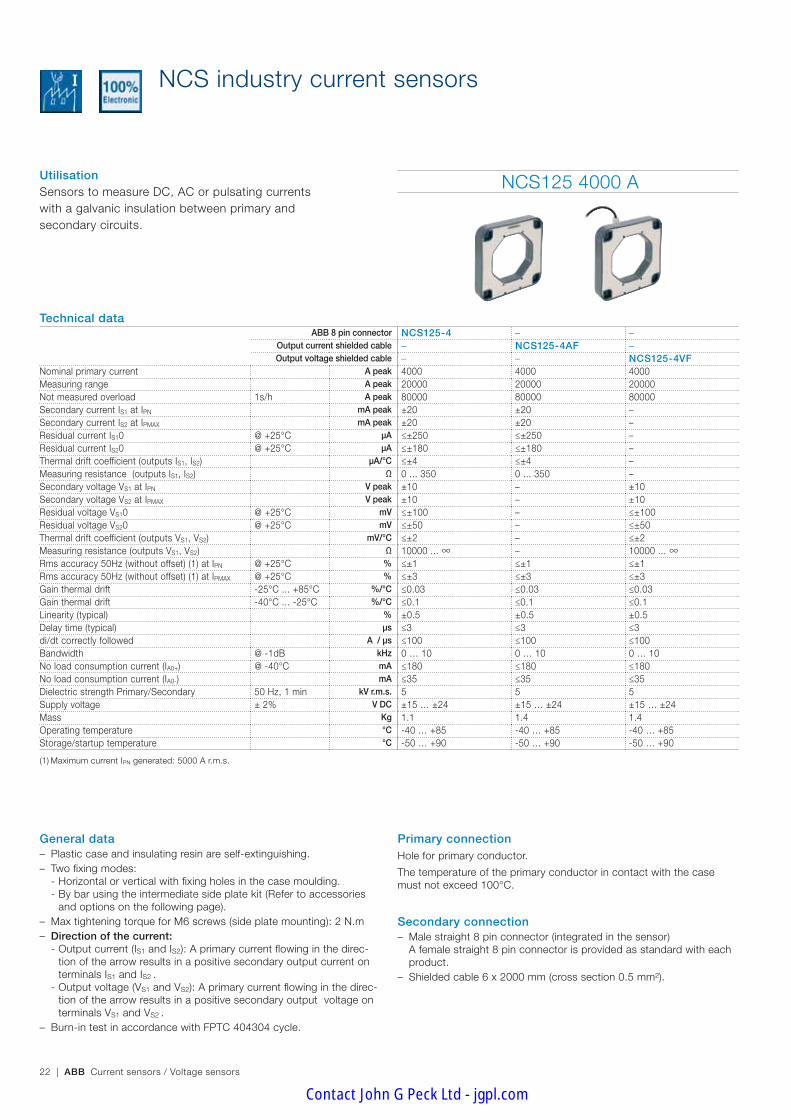
Nominal primary current A peak 4000 4000 4000Measuring range A peak 20000 20000 20000Not measured overload 1s/h A peak 80000 80000 80000Secondary current IS1 at IPN mA peak ±20 ±20 –Secondary current IS2 at IPMAX mA peak ±20 ±20 –Residual current IS10 @ +25°C µA ≤±250 ≤±250 –Residual current IS20 @ +25°C µA ≤±180 ≤±180 –Thermal drift coefficient (outputs IS1, IS2) µA/°C ≤±4 ≤±4 –Measuring resistance (outputs IS1, IS2) Ω 0 ... 350 0 ... 350 –Secondary voltage VS1 at IPN V peak ±10 – ±10Secondary voltage VS2 at IPMAX V peak ±10 – ±10Residual voltage VS10 @ +25°C mV ≤±100 – ≤±100Residual voltage VS20 @ +25°C mV ≤±50 – ≤±50Thermal drift coefficient (outputs VS1, VS2) mV/°C ≤±2 – ≤±2Measuring resistance (outputs VS1, VS2) Ω 10000 ... ∞ – 10000 ... ∞Rms accuracy 50Hz (without offset) (1) at IPN @ +25°C % ≤±1 ≤±1 ≤±1Rms accuracy 50Hz (without offset) (1) at IPMAX @ +25°C % ≤±3 ≤±3 ≤±3Gain thermal drift -25°C ... +85°C %/°C ≤0.03 ≤0.03 ≤0.03Gain thermal drift -40°C ... -25°C %/°C ≤0.1 ≤0.1 ≤0.1Linearity (typical) % ±0.5 ±0.5 ±0.5Delay time (typical) µs ≤3 ≤3 ≤3di/dt correctly followed A / µs ≤100 ≤100 ≤100Bandwidth @ -1dB kHz 0 … 10 0 … 10 0 … 10No load consumption current (IA0+) @ -40°C mA ≤180 ≤180 ≤180No load consumption current (IA0-) mA ≤35 ≤35 ≤35Dielectric strength Primary/Secondary 50 Hz, 1 min kV r.m.s. 5 5 5Supply voltage ± 2% V DC ±15 … ±24 ±15 … ±24 ±15 … ±24Mass Kg 1.1 1.4 1.4Operating temperature °C -40 … +85 -40 … +85 -40 … +85Storage/startup temperature °C -50 … +90 -50 … +90 -50 … +90
(1) Maximum current IPN generated: 5000 A r.m.s.
NCS industry current sensors
General data – Plastic case and insulating resin are self-extinguishing. – Two fixing modes:
- Horizontal or vertical with fixing holes in the case moulding. - By bar using the intermediate side plate kit (Refer to accessories and options on the following page).
– Max tightening torque for M6 screws (side plate mounting): 2 N.m – Direction of the current:
- Output current (IS1 and IS2): A primary current flowing in the direc-tion of the arrow results in a positive secondary output current on terminals IS1 and IS2 .
- Output voltage (VS1 and VS2): A primary current flowing in the direc-tion of the arrow results in a positive secondary output voltage on terminals VS1 and VS2 .
– Burn-in test in accordance with FPTC 404304 cycle.
Utilisation Sensors to measure DC, AC or pulsating currents with a galvanic insulation between primary and secondary circuits.
Primary connectionHole for primary conductor.
The temperature of the primary conductor in contact with the case must not exceed 100°C.
Secondary connection – Male straight 8 pin connector (integrated in the sensor) A female straight 8 pin connector is provided as standard with each product.
– Shielded cable 6 x 2000 mm (cross section 0.5 mm²).
Contact John G Peck Ltd - jgpl.com

Ind
ustr
y se
nso
rs
ABB Current sensors / Voltage sensors | 23
NCS125 from 6000 to 10000 A
Technical dataABB 8 pin connector NCS125-6 – – NCS125-10 – –
Output current shielded cable – NCS125-6AF – – NCS125-10AF –Output voltage shielded cable – – NCS125-6VF – – NCS125-10VF
Nominal primary current A peak 6000 6000 6000 10000 10000 10000Measuring range A peak 30000 30000 30000 30000 30000 30000Not measured overload 1s/h A peak 120000 120000 120000 200000 200000 200000Secondary current IS1 at IPN mA peak ±20 ±20 – ±20 ±20 –Secondary current IS2 at IPMAX mA peak ±20 ±20 – ±20 ±20 –Residual current IS10 @ +25°C µA ≤±250 ≤±250 – ≤±250 ≤±250 –Residual current IS20 @ +25°C µA ≤±180 ≤±180 – ≤±180 ≤±180 –Thermal drift coefficient (outputs IS1, IS2) µA/°C ≤±4 ≤±4 – ≤±4 ≤±4 –Measuring resistance (outputs IS1, IS2) Ω 0 ... 350 0 ... 350 – 0 ... 350 0 ... 350 –Secondary voltage VS1 at IPN V peak ±10 – ±10 ±10 – ±10Secondary voltage VS2 at IPMAX V peak ±10 – ±10 ±10 – ±10Residual voltage VS10 @ +25°C mV ≤±100 – ≤±100 ≤±100 – ≤±100Residual voltage VS20 @ +25°C mV ≤±50 – ≤±50 ≤±50 – ≤±50Thermal drift coefficient (outputs VS1, VS2) mV/°C ≤±2 – ≤±2 ≤±2 – ≤±2Measuring resistance (outputs VS1, VS2) Ω 10000 ... ∞ – 10000 ... ∞ 10000 ... ∞ – 10000 ... ∞Rms accuracy 50Hz (without offset) (1) at IPN @ +25°C % ≤±1 ≤±1 ≤±1 ≤±1 ≤±1 ≤±1Rms accuracy 50Hz (without offset) (1) at IPMAX @ +25°C % ≤±3 ≤±3 ≤±3 ≤±3 ≤±3 ≤±3Gain thermal drift -25°C ... +85°C %/°C ≤0.03 ≤0.03 ≤0.03 ≤0.03 ≤0.03 ≤0.03Gain thermal drift -40°C ... -25°C %/°C ≤0.1 ≤0.1 ≤0.1 ≤0.1 ≤0.1 ≤0.1Linearity (typical) % ±0.5 ±0.5 ±0.5 ±0.5 ±0.5 ±0.5Delay time (typical) µs ≤3 ≤3 ≤3 ≤3 ≤3 ≤3di/dt correctly followed A / µs ≤100 ≤100 ≤100 ≤100 ≤100 ≤100Bandwidth @ -1dB kHz 0 … 10 0 … 10 0 … 10 0 … 10 0 … 10 0 … 10No load consumption current (IA0+) @ -40°C mA ≤180 ≤180 ≤180 ≤180 ≤180 ≤180No load consumption current (IA0-) mA ≤35 ≤35 ≤35 ≤35 ≤35 ≤35Dielectric strength Primary/Secondary 50 Hz, 1 min kV r.m.s. 5 5 5 5 5 5Supply voltage ± 2% V DC ±15 … ±24 ±15 … ±24 ±15 … ±24 ±15 … ±24 ±15 … ±24 ±15 … ±24Mass Kg 1.1 1.4 1.4 1.1 1.4 1.4Operating temperature °C -40 … +85 -40 … +85 -40 … +85 -40 … +85 -40 … +85 -40 … +85Storage/startup temperature °C -50 … +90 -50 … +90 -50 … +90 -50 … +90 -50 … +90 -50 … +90
(1) Maximum current IPN generated: 5000 A r.m.s.
NCS industry current sensors
Accessories and options ABB female straight 8 pin connector
ABB order code: 1SBT200000R2003 including 10 lockable connectors
Side plates (or right angle brackets)
For installation of the side plates, please refer to the mounting instructions ref. 1SBC146005M1701-1 (NCS125) or the mounting instructions ref. 1SBC146004M1701-1 (NCS165)
Side plate kit NCS125:
ABB order code: 1SBT200000R2002
For other options please contact us.
ConformityEN50178
EN61000-6-2, EN61000-6-4
Contact John G Peck Ltd - jgpl.com
24 | ABB Current sensors / Voltage sensors
General data – Plastic case and insulating resin are self-extinguishing. – Two fixing modes:
- Horizontal or vertical with fixing holes in the case moulding. - By bar using the intermediate side plate kit (Refer to Accessories and options on the following page).
– Max tightening torque for M6 screws (side plate mounting): 2 N.m – Direction of the current:
- Output current (IS1 and IS2): A primary current flowing in the direc-tion of the arrow results in a positive secondary output current on terminals IS1 and IS2.
- Output voltage (VS1 and VS2): A primary current flowing in the direc-tion of the arrow results in a positive secondary output voltage on terminals VS1 and VS2.
– Burn-in test in accordance with FPTC 404304 cycle
NCS industry current sensors
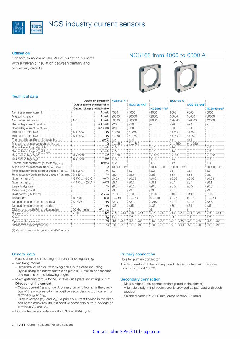
NCS165 from 4000 to 6000 A
Technical dataABB 8 pin connector NCS165-4 – – NCS165-6 – –
Output current shielded cable – NCS165-4AF – – NCS165-6AF –Output voltage shielded cable – – NCS165-4VF – – NCS165-6VF
Nominal primary current A peak 4000 4000 4000 6000 6000 6000Measuring range A peak 20000 20000 20000 30000 30000 30000Not measured overload 1s/h A peak 80000 80000 80000 120000 120000 120000Secondary current IS1 at IPN mA peak ±20 ±20 – ±20 ±20 –Secondary current IS2 at IPMAX mA peak ±20 ±20 – ±20 ±20 –Residual current IS10 @ +25°C µA ≤±250 ≤±250 – ≤±250 ≤±250 –Residual current IS20 @ +25°C µA ≤±180 ≤±180 – ≤±180 ≤±180 –Thermal drift coefficient (outputs IS1, IS2) µA/°C ≤±4 ≤±4 – ≤±4 ≤±4 –Measuring resistance (outputs IS1, IS2) Ω 0 ... 350 0 ... 350 – 0 ... 350 0 ... 350 –Secondary voltage VS1 at IPN V peak ±10 – ±10 ±10 – ±10Secondary voltage VS2 at IPMAX V peak ±10 – ±10 ±10 – ±10Residual voltage VS10 @ +25°C mV ≤±100 – ≤±100 ≤±100 – ≤±100Residual voltage VS20 @ +25°C mV ≤±50 – ≤±50 ≤±50 – ≤±50Thermal drift coefficient (outputs VS1, VS2) mV/°C ≤±2 – ≤±2 ≤±2 – ≤±2Measuring resistance (outputs VS1, VS2) Ω 10000 ... ∞ – 10000 ... ∞ 10000 ... ∞ – 10000 ... ∞Rms accuracy 50Hz (without offset) (1) at IPN @ +25°C % ≤±1 ≤±1 ≤±1 ≤±1 ≤±1 ≤±1Rms accuracy 50Hz (without offset) (1) at IPMAX @ +25°C % ≤±3 ≤±3 ≤±3 ≤±3 ≤±3 ≤±3Gain thermal drift -25°C ... +85°C %/°C ≤0.03 ≤0.03 ≤0.03 ≤0.03 ≤0.03 ≤0.03Gain thermal drift -40°C ... -25°C %/°C ≤0.1 ≤0.1 ≤0.1 ≤0.1 ≤0.1 ≤0.1Linearity (typical) % ±0.5 ±0.5 ±0.5 ±0.5 ±0.5 ±0.5Delay time (typical) µs ≤3 ≤3 ≤3 ≤3 ≤3 ≤3di/dt correctly followed A / µs ≤100 ≤100 ≤100 ≤100 ≤100 ≤100Bandwidth @ -1dB kHz 0 … 10 0 … 10 0 … 10 0 … 10 0 … 10 0 … 10No load consumption current (IA0+) @ -40°C mA ≤210 ≤210 ≤210 ≤210 ≤210 ≤210No load consumption current (IA0-) mA ≤35 ≤35 ≤35 ≤35 ≤35 ≤35Dielectric strength Primary/Secondary 50 Hz, 1 min kV r.m.s. 5 5 5 5 5 5Supply voltage ± 2% V DC ±15 … ±24 ±15 … ±24 ±15 … ±24 ±15 … ±24 ±15 … ±24 ±15 … ±24Mass Kg 1.4 1.7 1.7 1.4 1.7 1.7Operating temperature °C -40 … +85 -40 … +85 -40 … +85 -40 … +85 -40 … +85 -40 … +85Storage/startup temperature °C -50 … +90 -50 … +90 -50 … +90 -50 … +90 -50 … +90 -50 … +90
(1) Maximum current IPN generated: 5000 A r.m.s.
Utilisation Sensors to measure DC, AC or pulsating currents with a galvanic insulation between primary and secondary circuits.
Primary connectionHole for primary conductor.
The temperature of the primary conductor in contact with the case must not exceed 100°C.
Secondary connection – Male straight 8 pin connector (integrated in the sensor) A female straight 8 pin connector is provided as standard with each product.
– Shielded cable 6 x 2000 mm (cross section 0.5 mm²)
Contact John G Peck Ltd - jgpl.com
Ind
ustr
y se
nso
rs
ABB Current sensors / Voltage sensors | 25
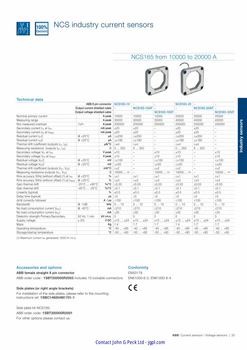
NCS165 from 10000 to 20000 A
Technical dataABB 8 pin connector NCS165-10 – – NCS165-20 – –
Output current shielded cable – NCS165-10AF – – NCS165-20AF –Output voltage shielded cable – – NCS165-10VF – – NCS165-20VF
Nominal primary current A peak 10000 10000 10000 20000 20000 20000Measuring range A peak 30000 30000 30000 40000 40000 40000Not measured overload 1s/h A peak 200000 200000 200000 200000 200000 200000Secondary current IS1 at IPN mA peak ±20 ±20 – ±20 ±20 –Secondary current IS2 at IPMAX mA peak ±20 ±20 – ±20 ±20 –Residual current IS10 @ +25°C µA ≤±250 ≤±250 – ≤±250 ≤±250 –Residual current IS20 @ +25°C µA ≤±180 ≤±180 – ≤±180 ≤±180 –Thermal drift coefficient (outputs IS1, IS2) µA/°C ≤±4 ≤±4 – ≤±4 ≤±4 –Measuring resistance (outputs IS1, IS2) Ω 0 ... 350 0 ... 350 – 0 ... 350 0 ... 350 –Secondary voltage VS1 at IPN V peak ±10 – ±10 ±10 – ±10Secondary voltage VS2 at IPMAX V peak ±10 – ±10 ±10 – ±10Residual voltage VS10 @ +25°C mV ≤±100 – ≤±100 ≤±100 – ≤±100Residual voltage VS20 @ +25°C mV ≤±50 – ≤±50 ≤±50 – ≤±50Thermal drift coefficient (outputs VS1, VS2) mV/°C ≤±2 – ≤±2 ≤±2 – ≤±2Measuring resistance (outputs VS1, VS2) Ω 10000 ... ∞ – 10000 ... ∞ 10000 ... ∞ – 10000 ... ∞Rms accuracy 50Hz (without offset) (1) at IPN @ +25°C % ≤±1 ≤±1 ≤±1 ≤±1 ≤±1 ≤±1Rms accuracy 50Hz (without offset) (1) at IPMAX @ +25°C % ≤±3 ≤±3 ≤±3 ≤±3 ≤±3 ≤±3Gain thermal drift -25°C ... +85°C %/°C ≤0.03 ≤0.03 ≤0.03 ≤0.03 ≤0.03 ≤0.03Gain thermal drift -40°C ... -25°C %/°C ≤0.1 ≤0.1 ≤0.1 ≤0.1 ≤0.1 ≤0.1Linearity (typical) % ±0.5 ±0.5 ±0.5 ±0.5 ±0.5 ±0.5Delay time (typical) µs ≤3 ≤3 ≤3 ≤3 ≤3 ≤3di/dt correctly followed A / µs ≤100 ≤100 ≤100 ≤100 ≤100 ≤100Bandwidth @ -1dB kHz 0 … 10 0 … 10 0 … 10 0 … 10 0 … 10 0 … 10No load consumption current (IA0+) @ -40°C mA ≤210 ≤210 ≤210 ≤210 ≤210 ≤210No load consumption current (IA0-) mA ≤35 ≤35 ≤35 ≤35 ≤35 ≤35Dielectric strength Primary/Secondary 50 Hz, 1 min kV r.m.s. 5 5 5 5 5 5Supply voltage ± 2% V DC ±15 … ±24 ±15 … ±24 ±15 … ±24 ±15 … ±24 ±15 … ±24 ±15 … ±24Mass Kg 1.4 1.7 1.7 1.4 1.7 1.7Operating temperature °C -40 … +85 -40 … +85 -40 … +85 -40 … +85 -40 … +85 -40 … +85Storage/startup temperature °C -50 … +90 -50 … +90 -50 … +90 -50 … +90 -50 … +90 -50 … +90
(1) Maximum current IPN generated: 5000 A r.m.s.
Accessories and options ABB female straight 8 pin connector
ABB order code : 1SBT200000R2003 includes 10 lockable connectors
Side plates (or right angle brackets)
For installation of the side plates, please refer to the mounting instructions ref. 1SBC146004M1701-1
Side plate kit NCS165:
ABB order code: 1SBT200000R2001
For other options please contact us.
NCS industry current sensors
ConformityEN50178
EN61000-6-2, EN61000-6-4
Contact John G Peck Ltd - jgpl.com

26 | ABB Current sensors / Voltage sensors
General data – Plastic case and insulating resin are self-extinguishing. – Clip on mounting mode – Two fixing modes:
- Horizontal with fixing holes in the case moulding. - By bar using the intermediate side plate kit (Refer to accessories and options on the following page).
– Max tightening torque for M6.3 screws (side plate mounting): 4.5 N.m – Direction of the current:
- Output current (IS1 and IS2): A primary current flowing in the direc-tion of the arrow results in a positive secondary output current on terminals IS1 and IS2.
- Output voltage (VS1 and VS2): A primary current flowing in the direc-tion of the arrow results in a positive secondary output voltage on terminals VS1 and VS2.
– Burn-in test in accordance with FPTC 404304 cycle.
Utilisation Sensors to measure DC, AC or pulsating currents with a galvanic insulation between primary and secondary circuits.
NCS305 from 6000 to 10000 A
Technical dataABB 8 pin connector NCS305-6 – – NCS305-10
Output current shielded cable – NCS305-6AF – –Output voltage shielded cable – – NCS305-6VF –
Nominal primary current A peak 6000 6000 6000 10000Measuring range A peak 20000 20000 20000 30000Not measured overload 1s/h A peak 80000 80000 80000 120000Secondary current IS1 at IPN mA peak ±20 ±20 – ±20Secondary current IS2 at IPMAX mA peak ±20 ±20 – ±20Residual current IS10 @ +25°C µA ≤ ±250 ≤ ±250 – ≤ ±250Residual current IS20 @ +25°C µA ≤ ±180 ≤ ±180 – ≤ ±180Thermal drift coefficient (outputs IS1, IS2) µA/°C ≤ ±4 ≤ ±4 – ≤ ±4Measuring resistance (outputs IS1, IS2) Ω 0 … 350 0 … 350 – 0 … 350Secondary voltage VS1 at IPN V peak ±10 – ±10 ±10Secondary voltage VS2 at IPMAX V peak ±10 – ±10 ±10Residual voltage VS10 @ +25°C mV ≤ ±100 – ≤ ±100 ≤ ±100Residual voltage VS20 @ +25°C mV ≤ ±50 – ≤ ±50 ≤ ±50Thermal drift coefficient (outputs VS1, VS2) mV/°C ≤ ±2 – ≤ ±2 ≤ ±2Measuring resistance (outputs VS1, VS2) Ω 10000 … ∞ – 10000 … ∞ 10000 … ∞Rms accuracy 50Hz (without offset) (1) at IPN @ +25°C % ≤ ±1 ≤ ±1 ≤ ±1 ≤ ±1Rms accuracy 50Hz (without offset) (1) at IPMAX @ +25°C % ≤ ±3 ≤ ±3 ≤ ±3 ≤ ±3Gain thermal drift -20°C ... +85°C %/°C ≤ ±0.01 ≤ ±0.01 ≤ ±0.01 ≤ ±0.01Gain thermal drift -40°C ... -20°C %/°C ≤ ±0.04 ≤ ±0.04 ≤ ±0.04 ≤ ±0.04Linearity (typical) % ±0.5 ±0.5 ±0.5 ±0.5Delay time (typical) µs ≤ 10 ≤ 10 ≤ 10 ≤ 10di/dt correctly followed A / µs ≤ 100 ≤ 100 ≤ 100 ≤ 100Bandwidth @ -1dB kHz 0 … 10 0 … 10 0 … 10 0 … 10No load consumption current (IA0+) @ -40°C mA ≤ 300 ≤ 300 ≤ 300 ≤ 300Dielectric strength Primary/Secondary 50 Hz, 1 min kV r.m.s. 5 5 5 5Supply voltage ± 2% V DC +15 … +24 +15 … +24 +15 … +24 +15 … +24Mass Kg 5.5 5.8 5.8 5.5Operating temperature °C -40 … +85 -40 … +85 -40 … +85 -40 … +85Storage/startup temperature °C -50 … +90 -50 … +90 -50 … +90 -50 … +90
(1) Maximum current IPN generated: 5000 A r.m.s.
NCS industry current sensors
Primary connectionHole for primary conductor.
The temperature of the primary conductor in contact with the case must not exceed 100°C.
Secondary connection – Male straight 8 pin connector (integrated in the sensor) A female straight 8 pin connector is provided as standard with each product.
– Shielded cable 6 x 2000 mm (cross section 0.5 mm²).
Contact John G Peck Ltd - jgpl.com

Ind
ustr
y se
nso
rs
ABB Current sensors / Voltage sensors | 27
Accessories and options ABB female straight 8 pin connector
ABB order code: 1SBT200000R2003 including 10 lockable connectors
Side plates
For installation of the side plates, please refer to the mounting instruc-tions ref. 1SBC146011M1701
Side plate kit NCS305:
ABB order code: 1SBT200000R2005
For other options please contact us.
NCS305 from 10000 to 20000 A
Technical dataABB 8 pin connector – – NCS305-20 – –
Output current shielded cable NCS305-10AF – – NCS305-20AF –Output voltage shielded cable – NCS305-10VF – – NCS305-20VF
Nominal primary current A peak 10000 10000 20000 20000 20000Measuring range A peak 30000 30000 40000 40000 40000Not measured overload 1s/h A peak 120000 120000 200000 200000 200000Secondary current IS1 at IPN mA peak ±20 – ±20 ±20 –Secondary current IS2 at IPMAX mA peak ±20 – ±20 ±20 –Residual current IS10 @ +25°C µA ≤ ±250 – ≤ ±250 ≤ ±250 –Residual current IS20 @ +25°C µA ≤ ±180 – ≤ ±180 ≤ ±180 –Thermal drift coefficient (outputs IS1, IS2) µA/°C ≤ ±4 – ≤ ±4 ≤ ±4 –Measuring resistance (outputs IS1, IS2) Ω 0 … 350 – 0 … 350 0 … 350 –Secondary voltage VS1 at IPN V peak – ±10 ±10 – ±10Secondary voltage VS2 at IPMAX V peak – ±10 ±10 – ±10Residual voltage VS10 @ +25°C mV – ≤ ±100 ≤ ±100 – ≤ ±100Residual voltage VS20 @ +25°C mV – ≤ ±50 ≤ ±50 – ≤ ±50Thermal drift coefficient (outputs VS1, VS2) mV/°C – ≤ ±2 ≤ ±2 – ≤ ±2Measuring resistance (outputs VS1, VS2) Ω – 10000 … ∞ 10000 … ∞ – 10000 … ∞Rms accuracy 50Hz (without offset) (1) at IPN @ +25°C % ≤ ±1 ≤ ±1 ≤ ±1 ≤ ±1 ≤ ±1Rms accuracy 50Hz (without offset) (1) at IPMAX @ +25°C % ≤ ±3 ≤ ±3 ≤ ±3 ≤ ±3 ≤ ±3Gain thermal drift -20°C ... +85°C %/°C ≤ ±0.01 ≤ ±0.01 ≤ ±0.01 ≤ ±0.01 ≤ ±0.01Gain thermal drift -40°C ... -20°C %/°C ≤ ±0.04 ≤ ±0.04 ≤ ±0.04 ≤ ±0.04 ≤ ±0.04Linearity (typical) % ±0.5 ±0.5 ±0.5 ±0.5 ±0.5Delay time (typical) µs ≤ 10 ≤ 10 ≤ 10 ≤ 10 ≤ 10di/dt correctly followed A / µs ≤ 100 ≤ 100 ≤ 100 ≤ 100 ≤ 100Bandwidth @ -1dB kHz 0 … 10 0 … 10 0 … 10 0 … 10 0 … 10No load consumption current (IA0+) @ -40°C mA ≤ 300 ≤ 300 ≤ 300 ≤ 300 ≤ 300Dielectric strength Primary/Secondary 50 Hz, 1 min kV r.m.s. 5 5 5 5 5Supply voltage ± 2% V DC +15 … +24 +15 … +24 +15 … +24 +15 … +24 +15 … +24Mass Kg 5.8 5.8 5.5 5.8 5.8Operating temperature °C -40 … +85 -40 … +85 -40 … +85 -40 … +85 -40 … +85Storage/startup temperature °C -50 … +90 -50 … +90 -50 … +90 -50 … +90 -50 … +90
(1) Maximum current IPN generated: 5000 A r.m.s.
NCS industry current sensors
ConformityEN50178
EN61000-6-2, EN61000-6-4
Contact John G Peck Ltd - jgpl.com
28 | ABB Current sensors / Voltage sensors
Dimensions (mm)
R18
37
1
32
45°
154,
3
162
154,3
162
Ø6,5
125
125
198
198
30
1
G02
36D
F
FT_NCS 19/10/05
R18
37
13
50
1
32
45°
24
154,
3
162
154,3
162
Ø6,5
125
125
198
198
30
1
G02
47D
F
FT_NCS 125_câble 11/10/05
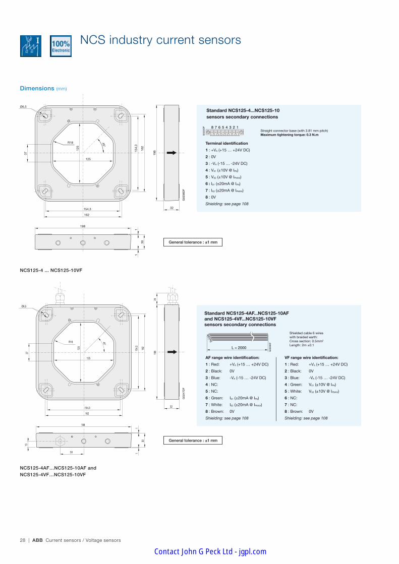
NCS125-4 ... NCS125-10VF
Standard NCS125-4...NCS125-10 sensors secondary connections
L = 2000
G02
28D
F
ES2000 05/10/05
G02
29D
F 8 7 6 5 4 3 2 1
connecteur verrouillable 05/10/05
Straight connector base (with 3.81 mm pitch)Maximum tightening torque: 0.3 N.m
Standard NCS125-4AF...NCS125-10AFand NCS125-4VF...NCS125-10VFsensors secondary connections
General tolerance : ±1 mm
Terminal identification
1 : +VA (+15 … +24V DC)
2 : 0V
3 : -VA (-15 … -24V DC)
4 : VS1 (±10V @ IPN)
5 : VS2 (±10V @ IPMAX)
6 : IS1 (±20mA @ IPN)
7 : IS2 (±20mA @ IPMAX)
8 : 0V
Shielding: see page 108
AF range wire identification:
1 : Red: +VA (+15 … +24V DC)
2 : Black: 0V
3 : Blue: -VA (-15 … -24V DC)
4 : NC:
5 : NC:
6 : Green: IS1 (±20mA @ IPN)
7 : White: IS2 (±20mA @ IPMAX)
8 : Brown: 0V
Shielding: see page 108
VF range wire identification:
1 : Red: +VA (+15 … +24V DC)
2 : Black: 0V
3 : Blue: -VA (-15 … -24V DC)
4 : Green: VS1 (±10V @ IPN)
5 : White: VS2 (±10V @ IPMAX)
6 : NC:
7 : NC:
8 : Brown: 0V
Shielding: see page 108
Shielded cable 6 wireswith braided earth:Cross section: 0.5mm2 Length: 2m ±0.1
General tolerance : ±1 mm
NCS125-4AF…NCS125-10AF andNCS125-4VF…NCS125-10VF
NCS industry current sensors
Contact John G Peck Ltd - jgpl.com

Ind
ustr
y se
nso
rs
ABB Current sensors / Voltage sensors | 29
Dimensions and arrangement of right angle brackets (mm)
104
92
41,5
70
10
2 screws M6x50 2 screws 3x12
200
46
92
80
200
...
204
(sta
ndar
d)
245
Max
i
145
Max
i
axis62 72
1655
90 56,5
Ø6,5
Ø6,5
2,5
Ø6,3
36
G02
30D
G
Kit 125_1 19/10/05
125
102
122
125
104
92
41,5
70
10
2 screws M6x50 2 screws 3x12
200
46
92
80
200
...
204
(sta
ndar
d)
245
Max
i
145
Max
i
axis
62 72
1655
90 56,5
Ø6,5
Ø6,5
2,5
Ø6,3
36
G02
30D
G
Kit 125_1 19/10/05
125
102
122
125
104
92
41,5
70
10
2 screws M6x50 2 screws 3x12
200
46
92
80
200
...
204
(sta
ndar
d)
245
Max
i
145
Max
i
axis
62 72
1655
90 56,5
Ø6,5
Ø6,5
2,5
Ø6,3
36
G02
30D
G
Kit 125_1 19/10/05
125
102
122
125
104
92
41,5
70
10
2 screws M6x50 2 screws 3x12
200
46
92
80
200
...
204
(sta
ndar
d)
245
Max
i
145
Max
i
axis
62 72
1655
90 56,5
Ø6,5
Ø6,5
2,5
Ø6,3
36
G02
30D
G
Kit 125_1 19/10/05
125
102
122
125
Kit125_1E_p25 et p59 26/10/05
4
5
6
2
3
4
1
6
5
4
1
2
G02
41D
F
50 %
60 %
4
5
6
2
3
4
1
6
5
4
1
2
4
5
6
2
3
4
1
6
5
4
1
2
Right angle brackets mounting on NCS125 sensors
1 - Side plate: x22 - Standard positioning screw: x2 (3x12)3 - Side plate screw M6: x2 (6x50)4 - Flat washer: x45 - Spring washer: x26 - Locknut: x27 - Not used: •SideplatescrewM6:x4(6x30) •Flatwasher:x4 •Springwasher:x2 •Locknut:x2
General tolerance : ±1 mm
NCS industry current sensors
Contact John G Peck Ltd - jgpl.com

30 | ABB Current sensors / Voltage sensors
Dimensions and arrangement of right angle brackets (mm)
102
122
125
125
13,4
min
i
200
31
121
Max
i
315
Max
i
62 8
16 21
Ø6,5 Ø6,3
G02
31D
F
Kit 125_2 19/10/05
165
90
200
102
122
12512
5
13,4
min
i
200
31
121
Max
i
315
Max
i
62 8
16 21
Ø6,5 Ø6,3
G02
31D
F
Kit 125_2 19/10/05
165
90
200
102
122
125
125
13,4
min
i
200
31
121
Max
i
315
Max
i
62 8
16 21
Ø6,5 Ø6,3
G02
31D
F
Kit 125_2 19/10/05
165
90
200
6
5
4
1
1
4
3
A
Kit125_2E_p26 et p60 26/10/05
50%60%
G02
42D
F
6
5
4
1
1
4
3
A
6
5
4
1
1
4
3
A
Right angle brackets mounting on NCS125 sensors
General tolerance : ±1 mm
1 - Side plate: x23 - Side plate screw M6: x4 (6x30)4 - Flat washer: x85 - Spring washer: x46 - Locknut: x47 - Not used: •SideplatescrewM6:x2(6x50) •Standardpositioningscrew:x2(3x12)
A - The screws for clamping the side plates to the bar (or cable) are not supplied
NCS industry current sensors
Contact John G Peck Ltd - jgpl.com

Ind
ustr
y se
nso
rs
ABB Current sensors / Voltage sensors | 31
Dimensions and arrangement of right angle brackets (mm)
50% 60%
Kit125_3E_p27 et p62 26/10/05
6
5
4
3
4
1
1
G02
43D
F
6
5
4
3
4
1
1
6
5
4
3
4
1
1
Right angle brackets mounting on NCS125 sensors
102
122
200
57
165
77
114
... 1
25
90
200
31
286
Max
Ø6,5 Ø6,5
16 21
62
3 nut prints H10 3 Ø6,3
5
G02
32D
G Kit 125_3 19/10/05
102
122
200
57
165
77
114
... 1
25
90
200
31
286
Max
Ø6,5 Ø6,5
16 21
62
3 nut prints H10 3 Ø6,3
5
G02
32D
G Kit 125_3 19/10/05
General tolerance : ±1 mm
102
122
200
57
165
77
114
... 1
25
90
200
31
286
Max
Ø6,5 Ø6,5
16 21
62
3 nut prints H10 3 Ø6,3
5
G02
32D
G Kit 125_3 19/10/05
1 - Side plate: x23 - Side plate screw M6: x4 (6x30)4 - Flat washer: x85 - Spring washer: x46 - Locknut: x47 - Not used: •SideplatescrewM6:x2(6x50) •Standardpositioningscrew:x2(3x12)
NCS industry current sensors
Contact John G Peck Ltd - jgpl.com
32 | ABB Current sensors / Voltage sensors
Dimensions (mm)
R2418
7
195
187
195
165
16548,5
240
30
11
240
45°
Ø6,5
32
G02
38D
F
FT_NCS 165 19/10/05
G02
37D
F
FT_NCS 165_câble 19/10/05
R24
24
13
50
187
195
187
195
165
16548,5
240
30
11
240
45°
Ø6,5
32
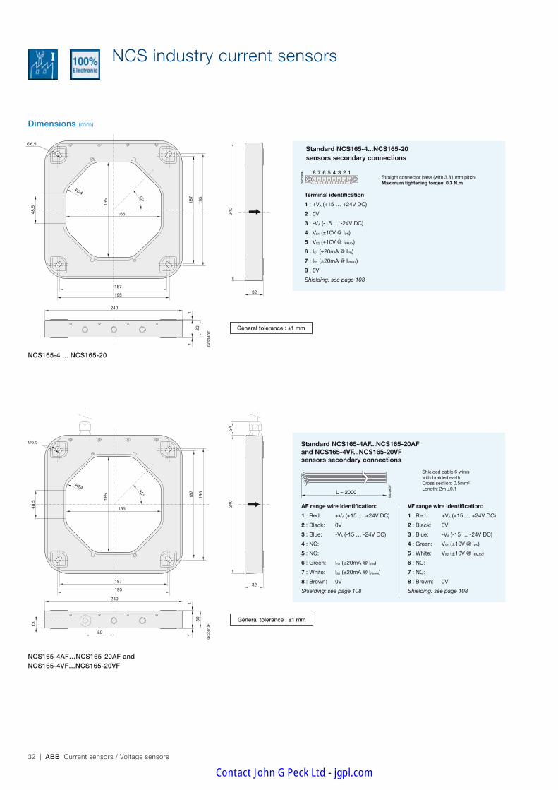
NCS165-4 ... NCS165-20
L = 2000
G02
28D
F
ES2000 05/10/05
Standard NCS165-4AF...NCS165-20AFand NCS165-4VF...NCS165-20VFsensors secondary connections
General tolerance : ±1 mm
Standard NCS165-4...NCS165-20 sensors secondary connections
G02
29D
F 8 7 6 5 4 3 2 1
connecteur verrouillable 05/10/05
Straight connector base (with 3.81 mm pitch)Maximum tightening torque: 0.3 N.m
Terminal identification
1 : +VA (+15 … +24V DC)
2 : 0V
3 : -VA (-15 … -24V DC)
4 : VS1 (±10V @ IPN)
5 : VS2 (±10V @ IPMAX)
6 : IS1 (±20mA @ IPN)
7 : IS2 (±20mA @ IPMAX)
8 : 0V
Shielding: see page 108
AF range wire identification:
1 : Red: +VA (+15 … +24V DC)
2 : Black: 0V
3 : Blue: -VA (-15 … -24V DC)
4 : NC:
5 : NC:
6 : Green: IS1 (±20mA @ IPN)
7 : White: IS2 (±20mA @ IPMAX)
8 : Brown: 0V
Shielding: see page 108
VF range wire identification:
1 : Red: +VA (+15 … +24V DC)
2 : Black: 0V
3 : Blue: -VA (-15 … -24V DC)
4 : Green: VS1 (±10V @ IPN)
5 : White: VS2 (±10V @ IPMAX)
6 : NC:
7 : NC:
8 : Brown: 0V
Shielding: see page 108
Shielded cable 6 wireswith braided earth:Cross section: 0.5mm2 Length: 2m ±0.1
General tolerance : ±1 mm
NCS165-4AF…NCS165-20AF andNCS165-4VF…NCS165-20VF
G02
37D
F
FT_NCS 165_câble 19/10/05
R24
24
13
50
187
195
187
195
165
16548,5
240
30
11
240
45°
Ø6,5
32
NCS industry current sensors
Contact John G Peck Ltd - jgpl.com

Ind
ustr
y se
nso
rs
ABB Current sensors / Voltage sensors | 33
Dimensions and arrangement of right angle brackets (mm)
axis
72
2005
5
Ø6,5
6,5
6,5
Ø6,5
62
90
Ø6,3
240
132
165
152
113
90142
122
102
10
10
10
49,5
92
46
80
36
2 screws 3x122 screws M6x50
240
...
252
(sta
ndar
d)
300
Max
i
180
Max
i
G02
33D
G
Kit 165_1 20/10/05
axis
72
2005
5
Ø6,5
6,5
6,5
Ø6,5
62
90
Ø6,3
240
132
165
152
113
90
142
122
10210
10
10
49,5
92
46
80
36
2 screws 3x122 screws M6x50
240
...
252
(sta
ndar
d)
300
Max
i
180
Max
i
G02
33D
G
Kit 165_1 20/10/05
axis
72
2005
5
Ø6,5
6,5
6,5
Ø6,5
62
90
Ø6,3
240
132
165
152
113
90
142
122
102
10
10
10
49,5
92
46
8036
2 screws 3x122 screws M6x50
240
...
252
(sta
ndar
d)
300
Max
i
180
Max
i
G02
33D
G
Kit 165_1 20/10/05
axis
72
2005
5
Ø6,5
6,5
6,5
Ø6,5
62
90
Ø6,3
240
132
165
152
113
90
142
122
102
10
10
10
49,5
92
46
80
36
2 screws 3x122 screws M6x50
240
...
252
(sta
ndar
d)
300
Max
i
180
Max
i
G02
33D
G
Kit 165_1 20/10/05
50% 60%
12
2
6
5
4
4
4
5
6
3
1
Kit165_1E_p29 et p63 26/10/05
12
2
6
5
4
4
4
5
6
3
G02
44D
F
1
12
2
6
5
4
4
4
5
6
3
1
Right angle brackets mounting on NCS165 sensors
General tolerance : ±1 mm
1 - Side plate: x22 - Standard positioning screw: x2 (3x12)3 - Side plate screw M6: x2 (6x50)4 - Flat washer: x45 - Spring washer: x26 - Locknut: x27 - Not used: •SideplatescrewM6:x4(6x30) •Flatwasher:x4 •Springwasher:x2 •Locknut:x2
NCS industry current sensors
Contact John G Peck Ltd - jgpl.com

34 | ABB Current sensors / Voltage sensors
Dimensions and arrangement of right angle brackets (mm)
165
165
16 21
Ø6,3Ø6,5
8
31
62
8 m
ini
154
Max
i
380
Max
i
102
122162 24
0G
0234
DF
Kit 165_2 20/10/05
240
200
90
16516
516 21
Ø6,3Ø6,5
8
31
62
8 m
ini
154
Max
i
380
Max
i
102
122162 24
0G
0234
DF
Kit 165_2 20/10/05
240
200
90
165
165
16 21
Ø6,3Ø6,5
8
31
62
8 m
ini
154
Max
i
380
Max
i
102
122162 24
0G
0234
DF
Kit 165_2 20/10/05
240
200
90
40%60%
Kit165_2E_p30 et p64 26/10/05
4
5
6
3
4
1
1
G02
45D
F
A
4
5
6
3
4
1
1
A
4
5
6
3
4
1
1
A
Right angle brackets mounting on NCS165 sensors
General tolerance : ±1 mm
1 - Side plate: x23 - Side plate screw M6: x4 (6x30)4 - Flat washer: x85 - Spring washer: x46 - Locknut: x47 - Not used: •SideplatescrewM6:x2(6x50) •Standardpositioningscrew:x2(3x12)
A - The screws for clamping the side plates to the bar (or cable) are not supplied
NCS industry current sensors
Contact John G Peck Ltd - jgpl.com

Ind
ustr
y se
nso
rs
ABB Current sensors / Voltage sensors | 35
Dimensions and arrangement of right angle brackets (mm)
50%60%
Kit165_3E_p31 et p65 26/10/05
5
4
1
1
6
3
4
G02
46D
F
5
4
1
1
6
3
4
5
4
1
1
6
3
4
Right angle brackets mounting on NCS165 sensors
102
122
142
15249
... 7
2
69 ..
. 92
89 ..
. 112
109
... 1
32
130
... 1
6562
21
360
Max
240
16
90
200
5
31240
Ø6,5 Ø6,5
3 Ø6,33 nut prints H10
G02
35D
G
Kit 165_3 20/10/05
102
122
142
152
49 ..
. 72
69 ..
. 92
89 ..
. 112
109
... 1
32
130
... 1
6562
21
360
Max
240
16
90
200
5
31240
Ø6,5 Ø6,5
3 Ø6,33 nut prints H10
G02
35D
G
Kit 165_3 20/10/05General tolerance : ±1 mm
102
122
142
152
49 ..
. 72
69 ..
. 92
89 ..
. 112
109
... 1
32
130
... 1
6562
21
360
Max
240
16
90
200
5
31240
Ø6,5 Ø6,5
3 Ø6,33 nut prints H10
G02
35D
G
Kit 165_3 20/10/05
1 - Side plate: x23 - Side plate screw M6: x4 (6x30)4 - Flat washer: x85 - Spring washer: x46 - Locknut: x47 - Not used: •SideplatescrewM6:x2(6x30) •Standardpositioningscrew:x2(3x12)
NCS industry current sensors
Contact John G Peck Ltd - jgpl.com
36 | ABB Current sensors / Voltage sensors
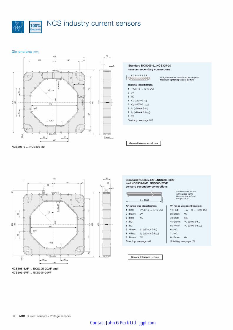
Dimensions (mm)
NCS305-6 ... NCS305-20
L = 2000
G02
28D
F
ES2000 05/10/05
Standard NCS305-6AF...NCS305-20AFand NCS305-6VF...NCS305-20VFsensors secondary connections
General tolerance : ±1 mm
Standard NCS305-6...NCS305-20 sensors secondary connections
G02
29D
F 8 7 6 5 4 3 2 1
connecteur verrouillable 05/10/05
Straight connector base (with 3.81 mm pitch)Maximum tightening torque: 0.3 N.m
Terminal identification
1 : +VA (+15 … +24V DC)
2 : 0V
3 : NC
4 : VS1 (±10V @ IPN)
5 : VS2 (±10V @ IPMAX)
6 : IS1 (±20mA @ IPN)
7 : IS2 (±20mA @ IPMAX)
8 : 0V
Shielding: see page 108
AF range wire identification:
1 : Red: +VA (+15 … +24V DC)
2 : Black: 0V
3 : Blue: NC
4 : NC:
5 : NC:
6 : Green: IS1 (±20mA @ IPN)
7 : White: IS2 (±20mA @ IPMAX)
8 : Brown: 0V
Shielding: see page 108
VF range wire identification:
1 : Red: +VA (+15 … +24V DC)
2 : Black: 0V
3 : Blue: NC
4 : Green: VS1 (±10V @ IPN)
5 : White: VS2 (±10V @ IPMAX)
6 : NC:
7 : NC:
8 : Brown: 0V
Shielding: see page 108
Shielded cable 6 wireswith braided earth:Cross section: 0.5mm2 Length: 2m ±0.1
General tolerance : ±1 mm
NCS305-6AF ... NCS305-20AF andNCS305-6VF ... NCS305-20VF
5050
405
430
190
50
190
50
50
130
1
430
167
167
1017
2
106,5
Ø8,
5
R24
302
302
45°
10
405
68
172
24
Ø4,
8 (x
32)
40
40
70
70
9 Maxi
5050
405
430
190
50
190
50
50
11
430
167
167
1017
2
106,5
Ø8,
5
R24
302
302
45°
10
405
172Ø
4,8
(x32
)
40
40
70
70
NCS industry current sensors
Contact John G Peck Ltd - jgpl.com

Ind
ustr
y se
nso
rs
ABB Current sensors / Voltage sensors | 37
420
350
Ø8,5 Ø8,5 ±0,05
30
82
302 Maxi
302
Max
i
106,5
430
408
80 m
ini
160
Max
i
1
2
1
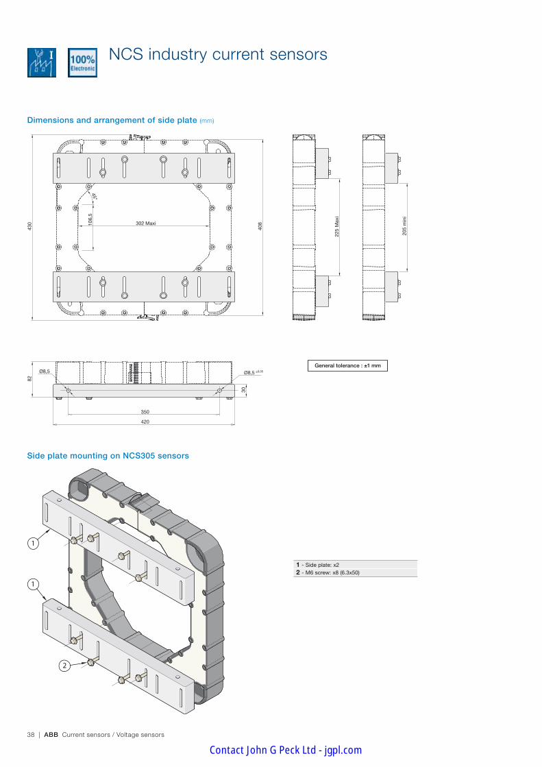
Dimensions and arrangement of side plate (mm)
Side plate mounting on NCS305 sensors
General tolerance : ±1 mm
1 - Side plate: x22 - M6 screw: x8 (6.3x50)
NCS industry current sensors
Contact John G Peck Ltd - jgpl.com
38 | ABB Current sensors / Voltage sensors
106,
5
45°
420
350
Ø8,5 Ø8,5 ±0,05
30
82
302 Maxi
430
408
225
Max
i
205
min
i
1
2
1
Dimensions and arrangement of side plate (mm)
Side plate mounting on NCS305 sensors
General tolerance : ±1 mm
1 - Side plate: x22 - M6 screw: x8 (6.3x50)
NCS industry current sensors
Contact John G Peck Ltd - jgpl.com

Ind
ustr
y se
nso
rs
ABB Current sensors / Voltage sensors | 39
Notes
Contact John G Peck Ltd - jgpl.com
40 | ABB Current sensors / Voltage sensors
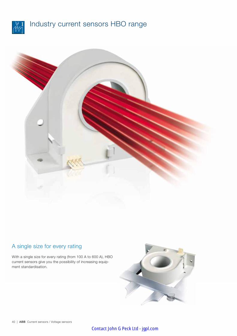
A single size for every rating
With a single size for every rating (from 100 A to 600 A), HBO current sensors give you the possibility of increasing equip-ment standardisation.
Industry current sensors HBO range
Contact John G Peck Ltd - jgpl.com

ABB Current sensors / Voltage sensors | 41
Ind
ustr
y se
nso
rs
LASER–TRIMMED SENSORS, AUTOMATED PRODUCTION
The chief selling-point of HBO sensors is their quality. Compliance of their high-tech electronic design with standard EN 50178 is proof of their ability to comply with the most detailed constraint as well as major demands. The fact that each individual sensor is subjected to rigorous testing is proof of the importance ABB attribute to quality.
ABB have long been concerned with the protection of the environment, as proved by the ISO 14001 certification they received in 1998. This environmental ap-proach is particularly noticeable in the production of the HBO range in the reduction of the number of components, in the use of a low-energy manufacturing procedure and the use of recyclable packing. The products in use are also character-ized by their reduced energy consumption.
Quality that goes beyond standards
ABB have been ISO 9001 certified since 1993 and our stan-dard HBO sensors bear the CE label in Europe. This ongoing striving after quality has always been the hall-mark of a company where excellence and safety are part of the culture, from design right through to production. This culture is the result of continuous research to make tech-nical progress and meet our customers' demands.
A precise response to customer expectations
The HBO sensor has been designed using Open Loop Hall effect technology, thereby adding a whole new type to the various sensor technologies used by ABB. The HBO range enables ABB to offer an additional range of sensors that are suitable for less technically demanding applications and en-sure best cost competitiveness. Customers are therefore free to choose the most suitable solution for their applications.
Vertical or horizontal
Assemblers can choose 2 methods of fastening ABB sensors: horizontally or vertically.
Ecology
Quality
Contact John G Peck Ltd - jgpl.com
42 | ABB Current sensors / Voltage sensors
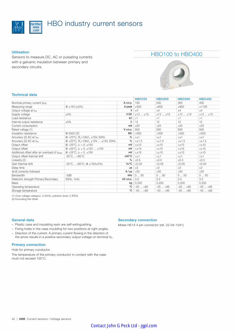
UtilisationSensors to measure DC, AC or pulsating currents with a galvanic insulation between primary and secondary circuits.
HBO100 to HBO400
Technical dataHBO100 HBO200 HBO300 HBO400
Nominal primary current (IPN) A r.m.s. 100 200 300 400Measuring range @ ±15V (±5%) A peak ±300 ±600 ±900 ±1100Output voltage at IPN V ±4 ±4 ±4 ±4Supply voltage ±5% V DC ±12 ... ±15 ±12 ... ±15 ±12 ... ±15 ±12 ... ±15Load resistance kΩ >1 >1 >1 >1Internal output resistance ±5% Ω 12 12 12 12Current consumption mA ≤25 ≤25 ≤25 ≤25Rated voltage (1) V r.m.s. 500 500 500 500Insulation resistance @ 500V DC MΩ >500 >500 >500 >500Accuracy (2) AC at IPN @ +25°C, RL>10kΩ, ±15V, 50Hz % ≤±1 ≤±1 ≤±1 ≤±1Accuracy (2) AC at IPN @ +25°C, RL>10kΩ, ±12V ... ±15V, 50Hz % ≤±1.5 ≤±1.5 ≤±1.5 ≤±1.5Output offset @ +25°C, IP = 0, ±15V mV ≤±10 ≤±10 ≤±10 ≤±10Output offset @ +25°C, IP = 0, ±12V ... ±15V mV ≤±15 ≤±15 ≤±15 ≤±15Additional offset after an overload of IPMAX @ +25°C, IP = 0, ±15V mV ≤±10 ≤±10 ≤±10 ≤±10Output offset thermal drift -25°C… +85°C mV/°C ≤±1 ≤±1 ≤±1 ≤±1Linearity (2) % ≤0.5 ≤0.5 ≤0.5 ≤0.5Gain thermal drift -25°C… +85°C, @ ±15V(±5%) %/°C ≤0.05 ≤0.05 ≤0.05 ≤0.05Delay time µs ≤3 ≤3 ≤3 ≤3di/dt correctly followed A / µs ≤50 ≤50 ≤50 ≤50Bandwidth -3dB kHz 0 ... 50 0 ... 50 0 ... 50 0 ... 50Dielectric strength Primary/Secondary 50Hz, 1min kV r.m.s. 3.5 3.5 3.5 3.5Mass kg 0.200 0.200 0.200 0.200Operating temperature °C -25 ... +85 -25 ... +85 -25 ... +85 -25 ... +85Storage temperature °C -40 ... +85 -40 ... +85 -40 ... +85 -40 ... +85
(1) Over voltage category: 3 (OV3), pollution level: 2 (PD2)(2) Excluding the offset
General data – Plastic case and insulating resin are self-extinguishing. – Fixing holes in the case moulding for two positions at right angles. – Direction of the current: A primary current flowing in the direction of the arrow results in a positive secondary output voltage on terminal VS.
Primary connectionHole for primary conductor.
The temperature of the primary conductor in contact with the case must not exceed 100°C.
HBO industry current sensors
Secondary connectionMolex HE14 4 pin connector (ref. 22-04-1041)
Contact John G Peck Ltd - jgpl.com

ABB Current sensors / Voltage sensors | 43
Ind
ustr
y se
nso
rs
Accessories and optionsFemale Molex connector – ABB order code: 1SBT210000R2001 including 10 housings and 40 crimp socket contacts
– Molex order code: socket housing: 22-01-1044; crimp socket contacts: 08-70-0057
HBO500 to HBO600
Technical dataHBO500 HBO600
Nominal primary current (IPN) A r.m.s. 500 600Measuring range @ ±15V (±5%) A peak ±1200 ±1300Output voltage at IPN V ±4 ±4Supply voltage ±5% V DC ±12 ... ±15 ±12 ... ±15Load resistance kΩ >1 >1Internal output resistance ±5% Ω 12 12Current consumption mA ≤25 ≤25Rated voltage (1) V r.m.s. 500 500Insulation resistance @ 500V DC MΩ >500 >500Accuracy (2) AC at IPN @ +25°C, RL>10kΩ, ±15V, 50Hz % ≤±1 ≤±1Accuracy (2) AC at IPN @ +25°C, RL>10kΩ, ±12V ... ±15V, 50Hz % ≤±1.5 ≤±1.5Output offset @ +25°C, IP = 0, ±15V mV ≤±10 ≤±10Output offset @ +25°C, IP = 0, ±12V ... ±15V mV ≤±15 ≤±15Additional offset after an overload of IPMAX @ +25°C, IP = 0, ±15V mV ≤±10 ≤±10Output offset thermal drift -25°C… +85°C mV/°C ≤±1 ≤±1Linearity (2) % ≤0.5 ≤0.5Gain thermal drift -25°C… +85°C, @ ±15V(±5%) %/°C ≤0.05 ≤0.05Delay time µs ≤3 ≤3di/dt correctly followed A / µs ≤50 ≤50Bandwidth -3dB kHz 0 ... 50 0 ... 50Dielectric strength Primary/Secondary 50Hz, 1min kV r.m.s. 3.5 3.5Mass kg 0.200 0.200Operating temperature °C -25 ... +85 -25 ... +85Storage temperature °C -40 ... +85 -40 ... +85
(1) Over voltage category: 3 (OV3), pollution level: 2 (PD2)(2) Excluding the offset
HBO industry current sensors
ConformityEN50178
Contact John G Peck Ltd - jgpl.com

44 | ABB Current sensors / Voltage sensors
1 4
1 2 3 4
8
25
Ø60
60
6
715
Ø4.6
21
5,5
Ø4,6
1,6
4,6
70 25
Ø32
2,5
3,5
40
70
12,5
78
90
G02
39D
F
FT_HBO 20/10/05
Molex Connector (with 2.50 mm pitch)
HBO100 to HBO600
Standard HBO100 to HBO600 sensors secondary connection
General tolerance : ±1 mm
Terminal 4 : 0VTerminal 3 : VS
Terminal 2 : -VA
Terminal 1 : +VA
G02
27D
F
connecteur 05/10/05
Terminal 4 : 0VTerminal 3 : VS
Terminal 2 : -VA
Terminal 1 : +VA
G02
27D
F
connecteur 05/10/05
Terminal 4 : 0VTerminal 3 : VS
Terminal 2 : -VA
Terminal 1 : +VA
G02
27D
F
connecteur 05/10/05
HBO industry current sensors
Dimensions (mm)
Contact John G Peck Ltd - jgpl.com

ABB Current sensors / Voltage sensors | 45
Ind
ustr
y se
nso
rs
Notes
Contact John G Peck Ltd - jgpl.com

46 | ABB Current sensors / Voltage sensors
Since obtaining ISO 14001 certification in 1998 ABB has integrated an essential concept into its ES current sensors: a determination to anticipate market requirements and genuine concern for the protection of the environment. This fundamen-tal concern is the overwhelming culture that permeates the company. No wonder our competitors are jealous and find our approach an inspiration for their own efforts. With the introduction of recyclable resin, ABB were trailblazers of an innovation that has over the years become a touchstone.
Smaller
As components get smaller but more powerful, installing cur-rent sensors is becoming a real problem. But with ABB's ES range, the whole thing is child's play. By being the first in the field to offer these smaller current sensors that maintain your high-performance objectives, ABB have met the challenge of giving you the space you always needed.
Industry current sensors ES range
It was this concept that enabled ABB to obtain ISO 14001 certification for their concern for the environ-ment. Optimized settings, waste control, minimization of losses, etc. are all factors that again ensure ABB pride of place in the field of current sensors.
The resin concept: a reference that has become a standard
Contact John G Peck Ltd - jgpl.com

ABB Current sensors / Voltage sensors | 47
Ind
ustr
y se
nso
rs
BECAUSE YOUR NEEDS ARE SPECIAL WE FIND YOU THE BEST SOLUTION
Horizontal or vertical mounting
Once again ABB lead the field by giving installers a chance to choose between two ways of fastening sensors: horizontally or vertically. This flexibility means that ES sensors can be installed in any position.This is a major breakthrough that greatly simplifies the task of systems integrators. The ES range is the ideal way of reduc-ing the size of equipment.
Quality that goes beyond standards
ABB have been ISO 9001 certified since 1993 and our ES range of sensors bear the CE label in Europe and the UL or UR labels in the US. This ongoing striving after quality has always been the hall-mark of a company where excellence and safety are part of the culture, from design right through to production. This culture is the result of continuous research to make technical progress and meet our customers' demands.
ABB have long been con-cerned with the protection of the environment, as proved by the ISO 14001 certification they received in 1998. This envi-ronmental approach is particularly noticeable in production of the ES range in the reduction of the number of components, in the use of a low-energy manufacturing procedure and the use of recyclable packing. The products in use are also char-acterized by their reduced energy consumption.
A vast range of possibilities for every type of use
Because ABB are in constant touch with their customers so that they can respond and adapt to the demands of the different sectors, they hold pride of place in their customers' list of partners. ABB are totally at home in the world of power electronics, a world made up of target sectors that range from power converters and auxiliary converters, inverters, wind-power generators, welding, robotics and active harmonic sup-pressors. ABB's power lies in their ability to adapt.
LSL USL
6σ
2 σ 308 537 69.2 %
3 σ 66 807 93.3 %
4 σ 6 210 99.4 %
5 σ 233 99.98 %
6 σ 3.4 99.9996 %
1,5 σ 4,5 σSTSTST
Sigma
Unacceptable
Average
Very good
Outstanding
Defects (PPM) Performance
Unbeatable reliability
Designed using the 6 sigma approach, the ES range is a model of reliability. The choice and number of optimized com-ponents, traceability of subassemblies, individually production tests… nothing is left to chance to guarantee your peace of mind.
The chief selling-point of ES sensors is their quality. Compliance of their high-tech electronic design with standard EN 50178 is proof of their ability to comply with the most detailed constraint as well as major demands.The fact that each individual sensor is subjected to rigorous testing is proof of the importance ABB attribute to quality.
Environment-friendly
Quality
Contact John G Peck Ltd - jgpl.com

48 | ABB Current sensors / Voltage sensors
ES industry current sensors
UtilisationSensors to measure DC, AC or pulsating currents with a galvanic insulation between primary and secondary circuits.
ES100 / ES300 / ES500
Technical dataMolex type HE14 connector ES100C ES300C ES500C ES500-9672
JST connector – ES300S ES500S ES500-9673Cables ES100F ES300F ES500F ES500-9674
Nominal primary current A r.m.s. 100 300 500 500Measuring range @ ±15V (±5%) A peak ±150 ±500 ±800 ±800Measuring range @ ±24V (±5%) A peak ±150 ±500 ±800 ±800Not measurable overload 10ms/hour A peak 300 (1ms/hour) 3000 5000 5000Max. measuring resistance @ IPMAX & ±15V (±5%) Ω 48 20 7 13Max. measuring resistance @ IPMAX & ±24V (±5%) Ω 105 54 60 56Min. measuring resistance @ IPN & ±15V (±5%) Ω 10 0 0 0Min. measuring resistance @ IPN & ±24V (±5%) Ω 82 45 0 14Turn number 1000 2000 5000 4000Secondary current at IPN mA 100 150 100 125Accuracy at IPN @ +25°C % ≤±0.5 ≤±0.5 ≤±0.5 ≤±0.5Accuracy at IPN -5 … +70°C % ≤±1 ≤±1 ≤±1 ≤±1Accuracy at IPN -20 … +70°C % ≤±2.5 ≤±1.5 ≤±1 ≤±1Offset current @ +25°C mA ≤±0.4 ≤±0.25 ≤±0.25 ≤±0.25Linearity % ≤0.1 ≤0.1 ≤0.1 ≤0.1Thermal drift coefficient -5 … +70°C µA/°C ≤10 ≤15 ≤5 ≤6.25Thermal drift coefficient -20 … +70°C µA/°C ≤80 ≤40 ≤16 ≤20Delay time µs ≤1 ≤1 ≤1 ≤1di/dt correctly followed A / µs ≤50 ≤50 ≤100 ≤100Bandwidth -1dB kHz ≤100 ≤100 ≤100 ≤100Max. no-load consumption current @ ±24V (±5%) mA ≤12 ≤12 ≤12 ≤12Secondary resistance @ +70°C Ω ≤30 ≤33 ≤76 ≤53Dielectric strength Primary/Secondary 50 Hz, 1 min kV 3 3 3 3Supply voltage ±5% V DC ±12 … ±24 ±12 … ±24 ±12 … ±24 ±12 … ±24Voltage drop V ≤2.5 ≤1 ≤1 ≤1Mass kg 0.050 0.115 0.210 0.210Operating temperature °C -20 … +70 -20 … +70 -20 … +70 -20 … +70Storage temperature °C -40 … +85 -40 … +85 -40 … +85 -40 … +85
General data – Plastic case and insulating resin are self-extinguishing. – Fixing holes in the case moulding for two positions at right angles. – Direction of the current: A primary current flowing in the direction of the
arrow results in a positive secondary output current from terminal M.
Primary connectionHole for primary conductor.
The temperature of the primary conductor in contact with the case must not exceed 100°C.
Secondary connection – Molex type HE14 connector – JST connector (ref.: B3P-VH) – 3 x 200 mm cables (cross section 0.38 mm²)
Contact John G Peck Ltd - jgpl.com

ABB Current sensors / Voltage sensors | 49
Ind
ustr
y se
nso
rs
ES1000 / ES2000
Technical data Molex type HE14 connector ES1000C ES1000-9678 ES2000C
JST connector ES1000S ES1000-9679 ES2000SCables ES1000F ES1000-9680 ES2000F
Nominal primary current A r.m.s. 1000 1000 2000Measuring range @ ±15V (±5%) A peak ±1500 ±1500 ±2200 (RM=5 Ω)Measuring range @ ±24V (±5%) A peak ±1500 ±1500 ±3000Not measurable overload 10ms/hour A peak 10000 10000 20000Max. measuring resistance @ IPMAX & ±15V (±5%) Ω 4 7 –Max. measuring resistance @ IPMAX & ±24V (±5%) Ω 33 30 11Min. measuring resistance @ IPN & ±15V (±5%) Ω 0 0 0Min. measuring resistance @ IPN & ±24V (±5%) Ω 0 0 0Turn number 5000 4000 5000Secondary current at IPN mA 200 250 400Accuracy at IPN @ +25°C % ≤±0.5 ≤±0.5 ≤±0.5Accuracy at IPN -5 … +70°C % ≤±1 ≤±1 ≤±1Accuracy at IPN -20 … +70°C % ≤±1 ≤±1 ≤±1Offset current @ +25°C mA ≤±0.25 ≤±0.25 ≤±0.25Linearity % ≤0.1 ≤0.1 ≤0.1Thermal drift coefficient -5 … +70°C µA/°C ≤5 ≤6.25 ≤10Thermal drift coefficient -20 … +70°C µA/°C ≤20 ≤20 ≤10Delay time µs ≤1 ≤1 ≤1di/dt correctly followed A / µs ≤100 ≤100 ≤100Bandwidth -1dB kHz ≤100 ≤100 ≤100Max. no-load consumption current @ ±24V (±5%) mA ≤12 ≤12 ≤25Secondary resistance @ +70°C Ω ≤40 ≤28 ≤25Dielectric strength Primary/Secondary 50 Hz, 1 min kV 3 3 4Supply voltage ±5% V DC ±12 … ±24 ±12 … ±24 ±15 … ±24Voltage drop V ≤1 ≤1 ≤1Mass kg 0.460 0.460 1.5Operating temperature °C -20 … +70 -20 … +70 -20 … +70Storage temperature °C -40 … +85 -40 … +85 -40 … +85
ES industry current sensors
Accessories and optionsFemale Molex connector – ABB order code: FPTN440032R0003 including 10 socket housings and 30 crimp socket contacts
– Molex order code: socket housing: 22-01-1034; crimp socket con-tacts: 08-70-0057.
Female JST connector – ABB order code: FPTN440032R0002 including 10 socket housings and 30 crimp socket contacts
– JST order code: socket housing: VHR-3N; crimp socket contacts: SVH-21T-1.1.
For other options, please contact us.
ConformityEN50178
EN61000-6-2, EN61000-6-4
: ES sensors with cables.
File number: E166814 Vol 1
: ES sensors with connectors.
File number: E166814 Vol 2
Contact John G Peck Ltd - jgpl.com

50 | ABB Current sensors / Voltage sensors
34
34
Ø 12
G00
86D
1
34
34
Ø 12
G00
86D
1
21
10.5 maxi1.5
3
41.5
21.5
1.5
G00
86D
2
21
10.5 maxi1.5
3
41.5
21.5
1.5
G00
86D
2
6 x Ø 3.3
40
45
51
9G
0086
D3
6 x Ø 3.3
40
45
51
9G
0086
D3
46
44
4644
Ø 20
R 2.15
G00
87D
1
10.5 maxi26
2 3
56
29
2.5
G00
87D
2
2 x Ø 4.3
54
60
68
12
6
G00
87D
3
57
57Ø 31
G00
88D
1
31 10.5 maxi
2.5 2
70
35
3
G00
88D
2
6 x Ø 4.3
70
77
89
15.510
G00
88D
3
ES100C / ES100F
ES300C / ES300S / ES300F ES500C / ES500S / ES500FES500-9672 / ES500-9673 / ES500-9674
Dimensions (mm)
Standard ES300... and ES500… sensors secondary connection
L = 200
G00
90D
Cable : - Red ................... +VA - Green ................ M - Black ................ -VA
M–
+ G00
92DM
–
+ G00
92D Molex type connector
(with 2.54 mm pitch)
M–
+ G00
91DM
–
+ G00
91D JST connector
(with 3.96 mm pitch)
M–
+ G00
92DM
–
+ G00
92D
L = 200
G00
90D
Standard ES100… sensors secondary connection
Cable : - Red ................... +VA - Green ................ M - Black ................ -VA
Molex type connector (with 2.54 mm pitch)
General tolerance : ±1 mmGeneral tolerance : ±1 mm
General tolerance : ±1 mm
ES industry current sensors
Contact John G Peck Ltd - jgpl.com

ABB Current sensors / Voltage sensors | 51
Ind
ustr
y se
nso
rs
78
78
Ø 40G
0089
D1
47.5
94.5
34
2.5 10.5 maxi
3
G00
89D
2
94
100
110
6 x Ø 5.3
1712
G00
89D
3
102
102
Ø 64
G01
06D
1
102
102
Ø 64
G01
06D
1
135
152
170
8 x Ø 6.5
113
30G
0106
D3
135
152
170
8 x Ø 6.5
113
30G
0106
D3
68.5
136
52
4 10.5 maxi
4
G01
06D
2
68.5
136
52
4 10.5 maxi
4
G01
06D
2
ES2000C / ES2000S / ES2000F
ES1000C / ES1000S / ES1000FES1000-9678 / ES1000-9679 / ES1000-9680
Dimensions (mm)
M–
+ G00
92DM
–
+ G00
92D
M–
+ G00
91DM
–
+ G00
91D
Standard ES1000... and ES2000…
sensors secondary connection
L = 200
G00
90D
Cable : - Red ................... +VA - Green ................ M - Black ................ -VA
Molex type connector (with 2.54 mm pitch)
JST connector (with 3.96 mm pitch)
General tolerance : ±1 mm
General tolerance : ±1 mm
ES industry current sensors
Contact John G Peck Ltd - jgpl.com

52 | ABB Current sensors / Voltage sensors
The resin concept: a reference that has become a standard
Since obtaining ISO 14001 certification in 1998 ABB has integrated an essential concept into its TYA current sensors: a determination to anticipate markets requirements and genuine concern for the protection of the environment. This funda-mental concern is the overwhelming culture that permeates the company. No wonder our competitors are jealous and find our approach an inspiration for their own efforts. With the introduction of recyclable resin, ABB where trailblazers of an innovation that has over the years become a touchstone. It was this concept that enabled ABB to obtain ISO 14001 certification for their concern for the environment. Optimized settings, waste control, minimization of losses, etc. are all factors that again ensure ABB pride of place in the field of current sensors.
A single size for two ratings
With a single size for two ratings (from 300 A to 500 A), TYA current sensors give you the possibility of increasing equipment standardization.
BECAUSE YOU SEARCH FOR PERFORMANCE WE MAKE THE DIFFERENCE
Quality that goes beyond standards
ABB have been ISO 9001 certified since 1993 and our TYA range of sensors bears the CE label in Europe and the ETL label that complies with the UL 508 and CSA C22.2. This out-going striving after quality has always been the hallmark of a company where excellence and safety are part of the culture, from design right through to production. This culture is the result of continuous research to make technical progress and meet our customers' demands.
Industry current sensors TYA range
The chief selling point of TYA sensor is their quality. Compliance of their high-tech electronic design with standard EN 50178 is proof of their ability to comply with the most detailed constraint as well as major demands. The fact that each individual sensor is subjected to rigorous testing is proof of the importance ABB attribute to quality.
ABB have long been concerned with the protection of the environment, as provided by the ISO 14001 certification they received in 1988. This environmental ap-proach is particularly noticeable in production of TYA range in the reduction of the number of components, in the use of a low-energy manufacturing procedure and the use of recy-clable packing. The products in use are also characterized by their reduced energy consumption.
Quality
Ecology
Contact John G Peck Ltd - jgpl.com

ABB Current sensors / Voltage sensors | 53
Ind
ustr
y se
nso
rs
ConformityEN50178, EN61000-6-2, EN61000-6-4
ETL file 4005175
UtilisationSensors to measure DC, AC or pulsating currents with a galvanic insulation between primary and secondary circuits.
General data – Plastic case and insulation resin are self-extinguishing. – Fixing holes in the case moulding for vertical mounting. – Direction of the current: a primary current flowing in the direction of the arrow results in a positive secondary output current from terminal M.
Primary connectionRectangular hole for primary conductor.
The temperature of the primary conductor in contact with the case must not exceed 100°C.
Secondary connectionMolex type HE14 connector
TYA industry current sensors
TYA300 / TYA500
Technical dataTYA300-1521 TYA300-2423 TYA500-1545 TYA500-2447
Nominal primary current A r.m.s. 300 300 400 500Measuring range @ ±15V (±5%) A peak ±600 – ±650 –Measuring range @ ±24V (±5%) A peak – ±450 – ±800Not measurable overload 10 msec/hour A peak ≤ ±3000 ≤ ±3000 ≤ ±5000 ≤ ±5000Max. measuring resistance @IPMAX & ±15V (±5%) Ω 10 – 13 –Max. measuring resistance @IPMAX & ±24V (±5%) Ω – 62 40Min. measuring resistance @IPN & ±15V (±5%) Ω 0 – 0 –Min. measuring resistance @IPN & ±24V (±5%) Ω – 61 – 26Turn number 1/2000 1/2000 1/4000 1/4000Secondary current (IS) at IPN mA 150 150 100 125Accuracy at IPN Without offset % ≤ ±0.5 ≤ ±0.5 ≤ ±0.5 ≤ ±0.5Offset current (ISO) Typical value mA ≤ ±0.5 ≤ ±0.5 ≤ ±0.25 ≤ ±0.25Linearity % ≤ ±0.1 ≤ ±0.1 ≤ ±0.1 ≤ ±0.1Thermal drift coefficient +25°C ... +85°C µA/°C ≤ 11 ≤ 11 ≤ 5 ≤ 5Thermal drift coefficient -40°C ... +25°C µA/°C ≤ 27 ≤ 27 ≤ 14 ≤ 14Delay time µs ≤ 1 ≤ 1 ≤ 1 ≤ 1di/dt correctly followed A/µs ≤ 50 ≤ 50 ≤ 50 ≤ 50Bandwidth -3dB kHz ≤ 50 ≤ 50 ≤ 50 ≤ 50No-load consumption current (IAO) @IP = 0 mA ≤ 25 ≤ 25 ≤ 25 ≤ 25Secondary resistance (RS) @+85°C Ω ≤ 33 ≤ 33 ≤ 67 ≤ 67Dielectric strength Primary/Secondary 50 Hz, 1 min kV r.m.s. 3 3 3 3Supply voltage ±5% V DC ±15 ±24 ±15 ±24Voltage drop (e') V DC ≤ 1 ≤ 1 ≤ 1 ≤ 1Mass kg 0.150 0.150 0.170 0.170Operating temperature °C -40 … +85 -40 … +85 -40 … +85 -40 … +85Storage temperature °C -40 … +90 -40 … +90 -40 … +90 -40 … +90
Contact John G Peck Ltd - jgpl.com
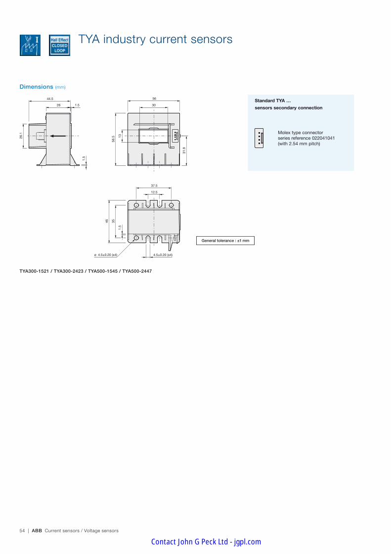
54 | ABB Current sensors / Voltage sensors
Molex type connector series reference 022041041(with 2.54 mm pitch)
TYA300-1521 / TYA300-2423 / TYA500-1545 / TYA500-2447
Standard TYA …
sensors secondary connection
TYA industry current sensors
Dimensions (mm)
General tolerance : ±1 mm
ø 4.5±0.20 (x4)
44.5
26 1.5
1.5
26.
1
56
30
56.
5 13
31.
9
1.5
35
46
12.5
37.5
4.5±0.20 (x4)
Contact John G Peck Ltd - jgpl.com

ABB Current sensors / Voltage sensors | 55
Ind
ustr
y se
nso
rs
Notes
Contact John G Peck Ltd - jgpl.com

56 | ABB Current sensors / Voltage sensors
MP and EL industry current sensors
Utilisation Sensors to measure DC, AC or pulsating currents with a galvanic insulation between primary and secondary circuits.Type MP25P1: the rating (from 5 to 25A) is deter-mined via a combination of the primary connections (see table: "Arrangement of primary terminals and related characteristics").
General dataDirection of the current: – MP25P1 Type: A primary current flowing from pins 1- 5 to pins
6-10 results in a positive secondary output current from terminal M.
– EL Type: A primary current flowing in the direction of the arrow results in a positive secondary output current from terminal M.
FixingBy soldering pins on printed circuit board.
Primary connection – MP25P1 Type: By 10 soldering pins. – EL Type: Hole for primary conductor (the temperature of the
primary conductor in contact with the case must not exceed 100°C)
– EL…BB type: Primary bar included.
MP25P1 EL25P1 to EL100P2EL25P1BB to EL100P2BB
Technical dataWithout primary bus bar – EL25P1 EL50P1 EL55P2 EL100P2
With primary bus bar MP25P1 EL25P1BB EL50P1BB EL55P2BB EL100P2BBNominal primary current A r.m.s. See data
page 5725 50 50 100
Measuring range @ ±15V (±5%) A peak ±55 ±80 ±80 ±145Max. measuring resistance @ IPMAX & ±15V (±5%) Ω 216 142 78 93 29Min. measuring resistance @ IPN & ±15V (±5%) & 70°C Ω 100 100 75 10 20Min. measuring resistance @ IPN & ±12V (±5%) & 70°C Ω 0 0 15 0 0Turn number See data
page 571000 1000 2000 2000
Secondary current at IPN mA 25 50 25 50Rms accuracy at IPN -20 … +70°C, sinus 50Hz % ≤±0.5 ≤±0.5 ≤±0.5 ≤±0.5 ≤±0.5Offset current @ +25°C mA ≤±0.1 ≤±0.2 ≤±0.2 ≤±0.2 ≤±0.2Linearity % ≤0.1 ≤0.1 ≤0.1 ≤0.1 ≤0.1Thermal drift coefficient -20 … +70°C µA/°C 7 7 7 7 7Delay time µs ≤0.1 ≤0.1 ≤0.1 ≤0.1 ≤0.1di/dt correctly followed A / µs ≤100 ≤200 ≤200 ≤150 ≤150Bandwidth -1dB kHz ≤150 ≤200 ≤200 ≤150 ≤150Max. no-load consumption current @ ±15V (±5%) mA ≤18 ≤20 ≤20 ≤20 ≤20Secondary resistance @ +70°C Ω ≤96 ≤63 ≤63 ≤188 ≤126Dielectric strength Primary/Secondary 50 Hz, 1 min kV 2.5 3 3 3 3Supply voltage ±5% V DC ±12 … ±15 ±12 … ±15 ±12 … ±15 ±12 … ±15 ±12 … ±15Voltage drop V ≤3 ≤3 ≤3 ≤3 ≤3Mass (EL type) kg – 0.020 0.020 0.020 0.020Mass (MP and EL…BB types) kg 0.027 0.027 0.027 0.027 0.027Operating temperature °C -20 …+70 -20 …+70 -20 …+70 -20 …+70 -20 …+70Storage temperature °C -25 … +85 -25 … +85 -25 … +85 -25 … +85 -25 … +85
Secondary connection3 soldering pins.
Unit packing – MP25P1 type: 40 per pack. – EL type: 50 per pack. – EL…BB type: 25 per pack.
Contact John G Peck Ltd - jgpl.com

ABB Current sensors / Voltage sensors | 57
Ind
ustr
y se
nso
rs
MP and EL industry current sensors
Dimensions (mm)
MP current sensors EL current sensors
EL…BB current sensors EL…BB: PCB layout
29
26.4
G01
42D
16.5
5
G01
43D
20.32
8.89 ø 1 x 133.5
8.12
4 x
2.54
7.62
7.62
5M
+15
–15
4321
6789
10
G01
44D
G01
49D
4.1
1.6
4.75
9.1 15.5
27.9
G01
52D
8.89 5.08 2 Holes ø 3.6
3 Holes ø 1.02
10.9
22.86
G01
71D
G
23.0
± 0
.2
3.0
r. 0.8x 2 places
4.4
G01
53D
G
40
11.5 12
3.1
25
0.6 x 0.7
27.946
5.08
G01
50D
40
11.5 12
3.1
25
0.6 x 0.7
27.946
5.08
G01
50D
G01
51D
+ - M
G01
45D
ø 10*
* Except EL 25 P1: ø = 7.5
17.5
5.08
40
25
12.5
0.6 x 0.7
6 27.94
G01
46D
GG
0147
D
+ - M
15.5
4.75
4.1
G01
48D
General tolerance : ±1 mm General tolerance : ±1 mm
General tolerance : ±1 mm
MP25P1: Arrangement of primary terminals and related characteristicsNominal primarycurrent
Measuring range @ ±15V (±5%)
Secondary currentat IPN
Turn ratio Primary resistance
Primary pinconnections
A r.m.s. A peak mA NP/NS mΩ
25 ±36 25 1/1000 0.3
out
in
12 ±18 24 2/1000 1.1
out
in
8 ±12 24 3/1000 2.5
out
in
6 ±9 24 4/1000 4.4
out
in
5 ±7 25 5/1000 6.3
out
in
Contact John G Peck Ltd - jgpl.com

58 | ABB Current sensors / Voltage sensors
Nominal primary current
Secondary current IS1 at ±IPN
Secondaryvoltage VS1 at ±IPN
Supply voltage
Secondary connection
Type Order code
A peak mA peak V peak V DC 4000 ±20 – ±24 Shielded cable
6 wires (2m)NCS125T-4AF 1SBT209204R0001
4000 – ±10 ±24 Shielded cable 6 wires (2m)
NCS125T-4VF 1SBT209204R0101
4000 ±20 – ±24 Shielded cable 6 wires (2m)
NCS165T-4AF 1SBT209604R0001
4000 – ±10 ±24 Shielded cable 6 wires (2m)
NCS165T-4VF 1SBT209604R0101
6000 ±20 – ±24 Shielded cable 6 wires (2m)
NCS125T-6AF 1SBT209206R0001
6000 – ±10 ±24 Shielded cable 6 wires (2m)
NCS125T-6VF 1SBT209206R0101
6000 ±20 – ±24 Shielded cable 6 wires (2m)
NCS165T-6AF 1SBT209606R0001
6000 – ±10 ±24 Shielded cable 6 wires (2m)
NCS165T-6VF 1SBT209606R0101
10000 ±20 – ±24 Shielded cable 6 wires (2m)
NCS125T-10AF 1SBT209210R0001
10000 – ±10 ±24 Shielded cable 6 wires (2m)
NCS125T-10VF 1SBT209210R0101
10000 ±20 – ±24 Shielded cable 6 wires (2m)
NCS165T-10AF 1SBT209610R0001
10000 – ±10 ±24 Shielded cable 6 wires (2m)
NCS165T-10VF 1SBT209610R0101
20000 ±20 – ±24 Shielded cable 6 wires (2m)
NCS165T-20AF 1SBT209620R0001
20000 – ±10 ±24 Shielded cable 6 wires (2m)
NCS165T-20VF 1SBT209620R0101NCS165T-4AF to NCS165-20AFNCS165T-4VF to NCS165-20VF
NCS125T-4AF to NCS125T-10AFNCS125T-4VF to NCS125T-10VF
These current sensors are specially designed and manufactured for Traction applications (NCS range for fixed railway applications and CS range for rolling stock). The requirements for these sensors are generally higher than those for Industry applications (larger operating temperature range, higher level of shocks and vibrations...).These sensors can be fixed mechanically, by the case or by the primary bar, depending on the version or option.
Frame mounting
Panorama of traction current sensorsFixed installations only
1SB
C14
6018
F001
4
1SB
C14
6017
F001
4
Contact John G Peck Ltd - jgpl.com
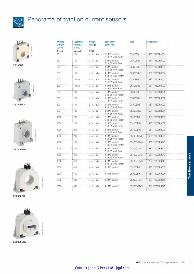
ABB Current sensors / Voltage sensors | 59
Trac
tio
n se
nso
rs
Panorama of traction current sensors
Nominal primary current
Secondary current IS1 at ± IPN
Supply voltage
Secondary connection
Type Order code
A peak mA peak V DC300 150 ±15 … ±24 3 x M5 studs //
3 x 6,35 x 0,8 FastonCS300BR 1SBT170300R0001
300 150 ±15 … ±24 3 x M5 studs // 3 x 6,35 x 0,8 Faston
CS300BRV 1SBT170300R0002
300 150 ±15 … ±24 4 x M5 studs // 4 x 6,35 x 0,8 Faston
CS300BRE 1SBT170300R0003
300 150 ±15 … ±24 4 x M5 studs // 4 x 6,35 x 0,8 Faston
CS300BRVE 1SBT170300R0004
500 142.86 ±15 … ±24 3 x M5 studs // 3 x 6,35 x 0,8 Faston
CS503BR 1SBT170503R0001
500 142.86 ±15 … ±24 4 x M5 studs // 4 x 6,35 x 0,8 Faston
CS503BRE 1SBT170503R0003
500 100 ±15 … ±24 3 x M5 studs // 3 x 6,35 x 0,8 Faston
CS500BR 1SBT170500R0001
500 100 ±15 … ±24 3 x M5 studs // 3 x 6,35 x 0,8 Faston
CS500BRV 1SBT170500R0002
500 100 ±15 … ±24 4 x M5 studs // 4 x 6,35 x 0,8 Faston
CS500BRE 1SBT170500R0003
500 100 ±15 … ±24 4 x M5 studs // 4 x 6,35 x 0,8 Faston
CS500BRVE 1SBT170500R0004
1000 200 ±15 … ±24 3 x M5 studs // 3 x 6,35 x 0,8 Faston
CS1000BR 1SBT171000R0001
1000 200 ±15 … ±24 3 x M5 studs // 3 x 6,35 x 0,8 Faston
CS1000BRV 1SBT171000R0002
1000 200 ±15 … ±24 4 x M5 studs // 4 x 6,35 x 0,8 Faston
CS1000BRE 1SBT171000R0003
1000 200 ±15 … ±24 4 x M5 studs // 4 x 6,35 x 0,8 Faston
CS1000BRVE 1SBT171000R0004
1000 250 ±15 … ±24 3 x M5 studs // 3 x 6,35 x 0,8 Faston
CS1000-9940 1SBT171000R9940
1000 250 ±15 … ±24 3 x M5 studs // 3 x 6,35 x 0,8 Faston
CS1000-9941 1SBT171000R9941
1000 250 ±15 … ±24 4 x M5 studs // 4 x 6,35 x 0,8 Faston
CS1000-9942 1SBT171000R9942
1000 250 ±15 … ±24 4 x M5 studs // 4 x 6,35 x 0,8 Faston
CS1000-9943 1SBT171000R9943
2000 400 ±15 … ±24 4 x M5 studs // CS2000BR 1SBT172000R0003
2000 400 ±15 … ±24 4 x M5 studs // CS2000BRV 1SBT172000R0004
2000 500 ±15 … ±24 4 x M5 studs // CS2000-9944 1SBT172000R9944
2000 500 ±15 … ±24 4 x M5 studs // CS2000-9945 1SBT172000R9945
CS300BR
CS300BRV
CS1000BRV
CS2000BRV
CS2000BR
1SB
C77
9142
F030
1
1SB
C77
9172
F030
1
1SB
C77
9152
F030
1
1SB
C78
9784
F030
21S
BC
7897
74F0
302
Contact John G Peck Ltd - jgpl.com

60 | ABB Current sensors / Voltage sensors
TYA300-T1521
1SB
C14
6024
F000
0
These sensors are designed to be fixed by the case.They may be either horizontally or vertically mounted.The secondary connection is made with a connector molded with the case.For TYA sensors the primary conductor may be a cable or a bar (better).
Frame mounting
Panorama of traction current sensors
Nominalprimary current
Secondarycurrentat IPN
Supplyvoltage
Secondary connection Type Order code
A r.m.s. mA V DC300 150 ±15 Molex serie
ref. 70543-0003TYA300-T1521 1SBT230300R0001
300 150 ±24 Molex serieref. 70543-0003
TYA300-T2423 1SBT230300R0003
400 100 ±15 Molex serieref. 70543-0003
TYA500-T1545 1SBT230500R0005
500 125 ±24 Molex serieref. 70543-0003
TYA500-T2447 1SBT230500R0007
Contact John G Peck Ltd - jgpl.com

ABB Current sensors / Voltage sensors | 61
Trac
tio
n se
nso
rs
Notes
Contact John G Peck Ltd - jgpl.com

62 | ABB Current sensors / Voltage sensors
165
mm
125
mm
Designed to be integrated into every situation
The NCS sensor is entirely symmetrical. Its square shape and strategically positioned oblong holes make it easy to fasten in a choice of 2 positions. As an accessory it comes with a side plate that can be fastened on either side of the sensor giving complete fitting flexibility. It meets the standard design of ABB current sensors. It can be fitted both horizontally and vertical-ly. This flexibility means that NCS sensors can be fitted in any position and simplifies the work of integrators. Additionally the pair of right angle brackets allows the NCS sensor to be fitted to one or several bars at the same time.
Substation current sensors NCS range
Contact John G Peck Ltd - jgpl.com

ABB Current sensors / Voltage sensors | 63
Sub
stat
ion
sens
ors
The chief selling-point of NCS sensors is their quality. Compliance of their high-tech electronic design with standard EN 50155 is proof of their ability to comply with the most detailed constraint as well as major demands. The fact that each individual sensor is subjected to rigorous testing is proof of the importance ABB attribute to quality.
THE NCS MEETS ALL OF YOUR REQUIREMENTS
100% electronic
The main advantage of the NCS range of sensors is that they are designed using a brand-new solution: 100% electronic technology. Unlike other currently available solutions such as shunts and CTs, this approach means that these sensors are very compact. Several patents were necessary to achieve this improvement.
Quality
ABB have long been concerned with the pro-tection of the environment, as proved by the ISO 14001 cer-tification they received in 1998. This environmental approach is particularly noticeable in the production of the NCS range in the reduction of the number of components, in the use of a low-energy manufacturing procedure and the use of recy-clable packing. The products in use are also characterized by their reduced energy consumption.
Quality that goes beyond standards
ABB have been ISO 9001 certified since 1993 and our stan-dard NCS sensors bear the CE label in Europe. This ongoing striving after quality has always been the hall-mark of a company where excellence and safety are part of the culture, from design right through to production. This culture is the result of continuous research to make tech-nical progress and meet our customers' demands.
Considerable energy savings
NCS sensors offer considerable savings in energy. Indeed only a few watts are required to power the NCS sensor in contrast to traditional sensors that require several hundred watts.This reduction in wasted energy means there is no rise in temperature around the sensor.
NCS Substation sensors have been designed to meet the substation standards EN50123-1 and EN50121-5. NCS range sensors also meet the security standard EN 50124-1.
Fixed installations only
Security
Ecology
Contact John G Peck Ltd - jgpl.com

64 | ABB Current sensors / Voltage sensors
General data – Plastic case and insulating resin are self-extinguishing. – Two fixing modes:
- Horizontal or vertical with fixing holes in the case moulding - By bar using the intermediate side plate kit (Refer to Accessories and options on the following page)
– Max tightening torque for M6 screws (side plate mounting): 2 N.m – Direction of the current:
- Output current (IS1 and IS2): A primary current flowing in the direc-tion of the arrow results in a positive secondary output current on terminals IS1 and IS2.
- Output voltage (VS1 and VS2): A primary current flowing in the direc-tion of the arrow results in a positive secondary output voltage on terminals VS1 and VS2.
– Burn-in test in accordance with FPTC 404304 cycle
NCS substation current sensorsFixed installations only
Utilisation Sensors to measure DC, AC or pulsating currents with a galvanic insulation between primary and secondary circuits.
NCS125T 4000 A
Technical dataOutput current shielded cable NCS125T-4AF –Output voltage shielded cable – NCS125T-4VF
Nominal primary current A peak 4000 4000Measuring range A peak 20000 20000Not measured overload 1s/h A peak 80000 80000Secondary current IS1 at IPN mA peak ±20 –Secondary current IS2 at IPMAX mA peak ±20 –Residual current IS10 @ +25°C µA ≤±250 –Residual current IS20 @ +25°C µA ≤±180 –Thermal drift coefficient (outputs IS1, IS2) µA/°C ≤±4 –Measuring resistance (outputs IS1, IS2) Ω 0 ... 350 –Secondary voltage VS1 at IPN V peak – ±10Secondary voltage VS2 at IPMAX V peak – ±10Residual voltage VS10 @ +25°C mV – ≤±100Residual voltage VS20 @ +25°C mV – ≤±50Thermal drift coefficient (outputs VS1, VS2) mV/°C – ≤±2Measuring resistance (outputs VS1, VS2) Ω – 10000 ... ∞Rms accuracy 50Hz (without offset) (1) at IPN @ +25°C % ≤±1 ≤±1Rms accuracy 50Hz (without offset) (1) at IPMAX @ +25°C % ≤±3 ≤±3Gain thermal drift -25°C ... +85°C %/°C ≤0.03 ≤0.03Gain thermal drift -40°C ... -25°C %/°C ≤0.1 ≤0.1Linearity (typical) % ±0.5 ±0.5Delay time (typical) µs ≤3 ≤3di/dt correctly followed A / µs ≤100 ≤100Bandwidth @ -1dB kHz 0 … 10 0 … 10No load consumption current (IA0+) @ -40°C mA ≤180 ≤180No load consumption current (IA0-) mA ≤35 ≤35Dielectric strength Primary/Secondary 50 Hz, 1 min kV r.m.s. 20 20Supply voltage ± 25% V DC ±24 ±24Mass Kg 1.4 1.4Operating temperature °C -40 … +85 -40 … +85Storage/startup temperature °C -50 … +90 -50 … +90
(1) Maximum current IPN generated: 5000 A r.m.s.
Primary connectionHole for primary conductor.
The temperature of the primary conductor in contact with the case must not exceed 100°C.
Secondary connectionShielded cable 6 x 2000 mm (cross section 0.5 mm²)
Contact John G Peck Ltd - jgpl.com
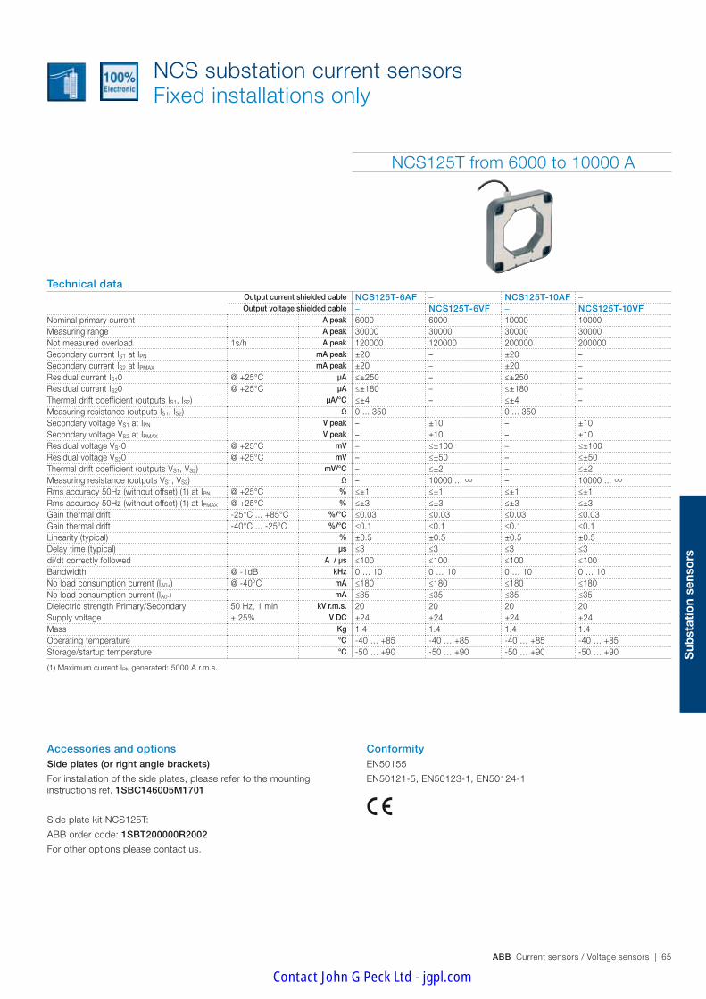
ABB Current sensors / Voltage sensors | 65
Sub
stat
ion
sens
ors
ConformityEN50155
EN50121-5, EN50123-1, EN50124-1
NCS substation current sensorsFixed installations only
Accessories and options Side plates (or right angle brackets)
For installation of the side plates, please refer to the mounting instructions ref. 1SBC146005M1701
Side plate kit NCS125T:
ABB order code: 1SBT200000R2002
For other options please contact us.
NCS125T from 6000 to 10000 A
Technical dataOutput current shielded cable NCS125T-6AF – NCS125T-10AF –Output voltage shielded cable – NCS125T-6VF – NCS125T-10VF
Nominal primary current A peak 6000 6000 10000 10000Measuring range A peak 30000 30000 30000 30000Not measured overload 1s/h A peak 120000 120000 200000 200000Secondary current IS1 at IPN mA peak ±20 – ±20 –Secondary current IS2 at IPMAX mA peak ±20 – ±20 –Residual current IS10 @ +25°C µA ≤±250 – ≤±250 –Residual current IS20 @ +25°C µA ≤±180 – ≤±180 –Thermal drift coefficient (outputs IS1, IS2) µA/°C ≤±4 – ≤±4 –Measuring resistance (outputs IS1, IS2) Ω 0 ... 350 – 0 ... 350 –Secondary voltage VS1 at IPN V peak – ±10 – ±10Secondary voltage VS2 at IPMAX V peak – ±10 – ±10Residual voltage VS10 @ +25°C mV – ≤±100 – ≤±100Residual voltage VS20 @ +25°C mV – ≤±50 – ≤±50Thermal drift coefficient (outputs VS1, VS2) mV/°C – ≤±2 – ≤±2Measuring resistance (outputs VS1, VS2) Ω – 10000 ... ∞ – 10000 ... ∞ Rms accuracy 50Hz (without offset) (1) at IPN @ +25°C % ≤±1 ≤±1 ≤±1 ≤±1Rms accuracy 50Hz (without offset) (1) at IPMAX @ +25°C % ≤±3 ≤±3 ≤±3 ≤±3Gain thermal drift -25°C ... +85°C %/°C ≤0.03 ≤0.03 ≤0.03 ≤0.03Gain thermal drift -40°C ... -25°C %/°C ≤0.1 ≤0.1 ≤0.1 ≤0.1Linearity (typical) % ±0.5 ±0.5 ±0.5 ±0.5Delay time (typical) µs ≤3 ≤3 ≤3 ≤3di/dt correctly followed A / µs ≤100 ≤100 ≤100 ≤100Bandwidth @ -1dB kHz 0 … 10 0 … 10 0 … 10 0 … 10No load consumption current (IA0+) @ -40°C mA ≤180 ≤180 ≤180 ≤180No load consumption current (IA0-) mA ≤35 ≤35 ≤35 ≤35Dielectric strength Primary/Secondary 50 Hz, 1 min kV r.m.s. 20 20 20 20Supply voltage ± 25% V DC ±24 ±24 ±24 ±24Mass Kg 1.4 1.4 1.4 1.4Operating temperature °C -40 … +85 -40 … +85 -40 … +85 -40 … +85Storage/startup temperature °C -50 … +90 -50 … +90 -50 … +90 -50 … +90
(1) Maximum current IPN generated: 5000 A r.m.s.
Contact John G Peck Ltd - jgpl.com
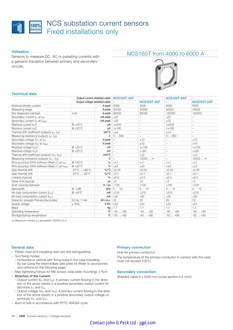
66 | ABB Current sensors / Voltage sensors
General data – Plastic case and insulating resin are self-extinguishing. – Two fixing modes:
- Horizontal or vertical with fixing holes in the case moulding. - By bar using the intermediate side plate kit (Refer to accessories and options on the following page)
– Max tightening torque for M6 screws (side plate mounting): 2 N.m – Direction of the current:
- Output current (IS1 and IS2): A primary current flowing in the direc-tion of the arrow results in a positive secondary output current on terminals IS1 and IS2.
- Output voltage (VS1 and VS2): A primary current flowing in the direc-tion of the arrow results in a positive secondary output voltage on terminals VS1 and VS2.
– Burn-in test in accordance with FPTC 404304 cycle
NCS substation current sensorsFixed installations only
Utilisation Sensors to measure DC, AC or pulsating currents with a galvanic insulation between primary and secondary circuits.
NCS165T from 4000 to 6000 A
Technical dataOutput current shielded cable NCS165T-4AF – NCS165T-6AF –Output voltage shielded cable – NCS165T-4VF – NCS165T-6VF
Nominal primary current A peak 4000 4000 6000 6000Measuring range A peak 20000 20000 30000 30000Not measured overload 1s/h A peak 80000 80000 120000 120000Secondary current IS1 at IPN mA peak ±20 – ±20 –Secondary current IS2 at IPMAX mA peak ±20 – ±20 –Residual current IS10 @ +25°C µA ≤±250 – ≤±250 –Residual current IS20 @ +25°C µA ≤±180 – ≤±180 –Thermal drift coefficient (outputs IS1, IS2) µA/°C ≤±4 – ≤±4 –Measuring resistance (outputs IS1, IS2) Ω 0 ... 350 – 0 ... 350 –Secondary voltage VS1 at IPN V peak – ±10 – ±10Secondary voltage VS2 at IPMAX V peak – ±10 – ±10Residual voltage VS10 @ +25°C mV – ≤±100 – ≤±100Residual voltage VS20 @ +25°C mV – ≤±50 – ≤±50Thermal drift coefficient (outputs VS1, VS2) mV/°C – ≤±2 – ≤±2Measuring resistance (outputs VS1, VS2) Ω – 10000 ... ∞ – 10000 ... ∞ Rms accuracy 50Hz (without offset) (1) at IPN @ +25°C % ≤±1 ≤±1 ≤±1 ≤±1Rms accuracy 50Hz (without offset) (1) at IPMAX @ +25°C % ≤±3 ≤±3 ≤±3 ≤±3Gain thermal drift -25°C ... +85°C %/°C ≤0.03 ≤0.03 ≤0.03 ≤0.03Gain thermal drift -40°C ... -25°C %/°C ≤0.1 ≤0.1 ≤0.1 ≤0.1Linearity (typical) % ±0.5 ±0.5 ±0.5 ±0.5Delay time (typical) µs ≤3 ≤3 ≤3 ≤3di/dt correctly followed A / µs ≤100 ≤100 ≤100 ≤100Bandwidth @ -1dB kHz 0 … 10 0 … 10 0 … 10 0 … 10No load consumption current (IA0+) @ -40°C mA ≤210 ≤210 ≤210 ≤210No load consumption current (IA0-) mA ≤35 ≤35 ≤35 ≤35Dielectric strength Primary/Secondary 50 Hz, 1 min kV r.m.s. 20 20 20 20Supply voltage ± 25% V DC ±24 ±24 ±24 ±24Mass Kg 1.7 1.7 1.7 1.7Operating temperature °C -40 … +85 -40 … +85 -40 … +85 -40 … +85Storage/startup temperature °C -50 … +90 -50 … +90 -50 … +90 -50 … +90
(1) Maximum current IPN generated: 5000A r.m.s.
Primary connectionHole for primary conductor.
The temperature of the primary conductor in contact with the case must not exceed 100°C.
Secondary connectionShielded cable 6 x 2000 mm (cross section 0.5 mm²)
Contact John G Peck Ltd - jgpl.com

ABB Current sensors / Voltage sensors | 67
Sub
stat
ion
sens
ors
NCS substation current sensorsFixed installations only
Accessories and options Side plates (or right angle brackets)
For installation of the side plates, please refer to the mounting instructions ref. 1SBC146004M1701
Side plate kit NCS165T:
ABB order code: 1SBT200000R2001
For other options please contact us.
NCS165T from 10000 to 20000 A
Technical dataOutput current shielded cable NCS165T-10AF – NCS165T-20AF –Output voltage shielded cable – NCS165T-10VF – NCS165T-20VF
Nominal primary current A peak 10000 10000 20000 20000Measuring range A peak 30000 30000 40000 40000Not measured overload 1s/h A peak 200000 200000 200000 200000Secondary current IS1 at IPN mA peak ±20 – ±20 –Secondary current IS2 at IPMAX mA peak ±20 – ±20 –Residual current IS10 @ +25°C µA ≤±250 – ≤±250 –Residual current IS20 @ +25°C µA ≤±180 – ≤±180 –Thermal drift coefficient (outputs IS1, IS2) µA/°C ≤±4 – ≤±4 –Measuring resistance (outputs IS1, IS2) Ω 0 ... 350 – 0 ... 350 –Secondary voltage VS1 at IPN V peak – ±10 – ±10Secondary voltage VS2 at IPMAX V peak – ±10 – ±10Residual voltage VS10 @ +25°C mV – ≤±100 – ≤±100Residual voltage VS20 @ +25°C mV – ≤±50 – ≤±50Thermal drift coefficient (outputs VS1, VS2) mV/°C – ≤±2 – ≤±2Measuring resistance (outputs VS1, VS2) Ω – 10000 ... ∞ – 10000 ... ∞ Rms accuracy 50Hz (without offset)1 at IPN @ +25°C % ≤±1 ≤±1 ≤±1 ≤±1Rms accuracy 50Hz (without offset)1 at IPMAX @ +25°C % ≤±3 ≤±3 ≤±3 ≤±3Gain thermal drift -25°C ... +85°C %/°C ≤0.03 ≤0.03 ≤0.03 ≤0.03Gain thermal drift -40°C ... -25°C %/°C ≤0.1 ≤0.1 ≤0.1 ≤0.1Linearity (typical) % ±0.5 ±0.5 ±0.5 ±0.5Delay time (typical) µs ≤3 ≤3 ≤3 ≤3di/dt correctly followed A / µs ≤100 ≤100 ≤100 ≤100Bandwidth @ -1dB kHz 0 … 10 0 … 10 0 … 10 0 … 10No load consumption current (IA0+) @ -40°C mA ≤210 ≤210 ≤210 ≤210No load consumption current (IA0-) mA ≤35 ≤35 ≤35 ≤35Dielectric strength Primary/Secondary 50 Hz, 1 min kV r.m.s. 20 20 20 20Supply voltage ± 25% V DC ±24 ±24 ±24 ±24Mass Kg 1.7 1.7 1.7 1.7Operating temperature °C -40 … +85 -40 … +85 -40 … +85 -40 … +85Storage/startup temperature °C -50 … +90 -50 … +90 -50 … +90 -50 … +90
(1) Maximum current IPN generated: 5000 A r.m.s.
ConformityEN50155
EN50121-5, EN50123-1, EN50124-1
Contact John G Peck Ltd - jgpl.com
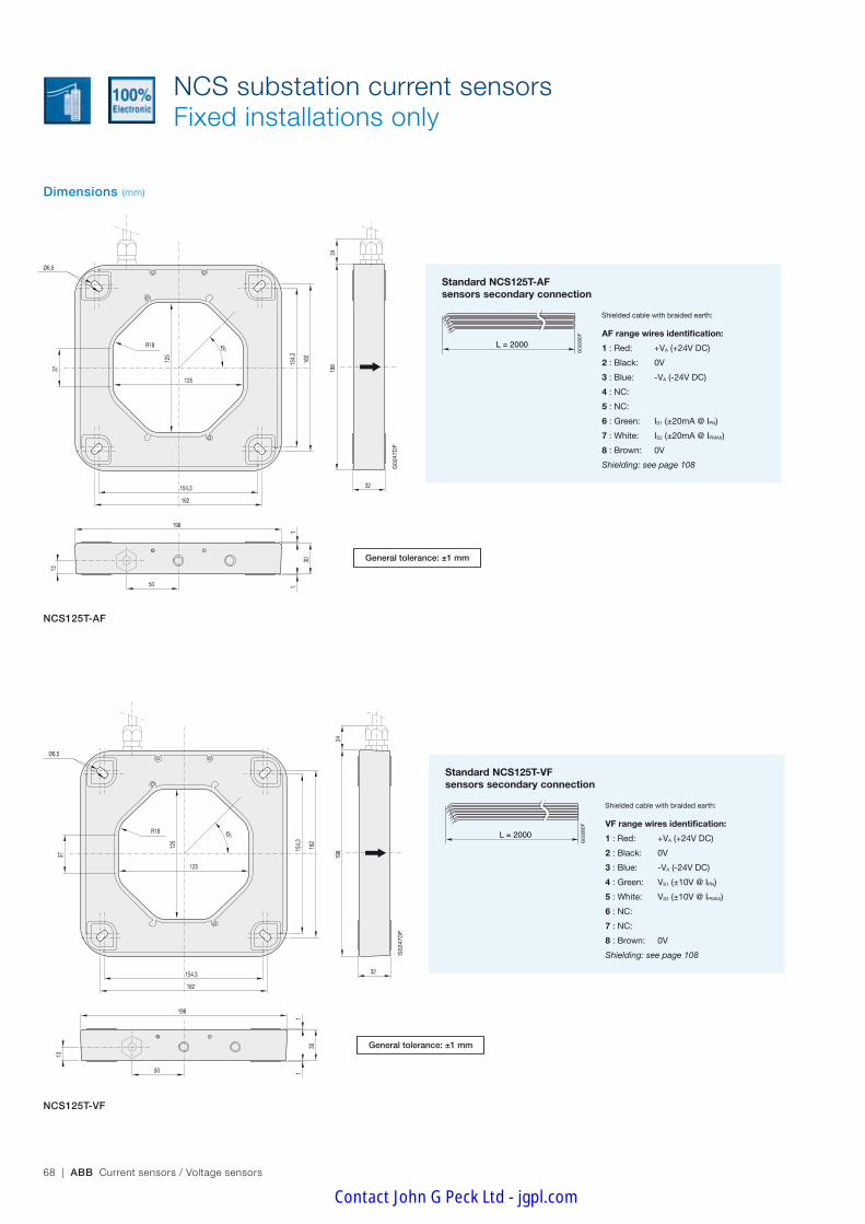
68 | ABB Current sensors / Voltage sensors
NCS substation current sensors Fixed installations only
R18
37
13
50
1
32
45°
24
154,
3
162
154,3
162
Ø6,5
125
125
198
198
30
1
G02
47D
F
FT_NCS 125_câble 11/10/05
R18
37
13
50
1
32
45°
24
154,
3
162
154,3
162
Ø6,5
125
125
198
198
30
1
G02
47D
F
FT_NCS 125_câble 11/10/05NCS125T-AF
General tolerance: ±1 mm
General tolerance: ±1 mm
NCS125T-VF
L = 2000
G02
28D
F
ES2000 05/10/05
Standard NCS125T-AFsensors secondary connection
AF range wires identification:
1 : Red: +VA (+24V DC)
2 : Black: 0V
3 : Blue: -VA (-24V DC)
4 : NC:
5 : NC:
6 : Green: IS1 (±20mA @ IPN)
7 : White: IS2 (±20mA @ IPMAX)
8 : Brown: 0V
Shielding: see page 108
Shielded cable with braided earth:
L = 2000
G02
28D
F
ES2000 05/10/05
Standard NCS125T-VFsensors secondary connection
VF range wires identification:
1 : Red: +VA (+24V DC)
2 : Black: 0V
3 : Blue: -VA (-24V DC)
4 : Green: VS1 (±10V @ IPN)
5 : White: VS2 (±10V @ IPMAX)
6 : NC:
7 : NC:
8 : Brown: 0V
Shielding: see page 108
Shielded cable with braided earth:
Dimensions (mm)
Contact John G Peck Ltd - jgpl.com

ABB Current sensors / Voltage sensors | 69
Sub
stat
ion
sens
ors
NCS substation current sensors Fixed installations only
Dimensions and arrangement of right angle brackets (mm)
104
92
41,5
70
10
2 screws M6x50 2 screws 3x12
200
46
92
80
200
...
204
(sta
ndar
d)
245
Max
i
145
Max
i
axis
62 72
1655
90 56,5
Ø6,5
Ø6,5
2,5
Ø6,3
36
G02
30D
G
Kit 125_1 19/10/05
125
102
122
125
104
92
41,5
70
10
2 screws M6x50 2 screws 3x12
200
46
92
80
200
...
204
(sta
ndar
d)
245
Max
i
145
Max
i
axis
62 72
1655
90 56,5
Ø6,5
Ø6,5
2,5
Ø6,3
36
G02
30D
G
Kit 125_1 19/10/05
125
102
122
125
104
92
41,5
70
10
2 screws M6x50 2 screws 3x12
200
46
92
80
200
...
204
(sta
ndar
d)
245
Max
i
145
Max
i
axis62 72
1655
90 56,5
Ø6,5
Ø6,5
2,5
Ø6,3
36
G02
30D
G
Kit 125_1 19/10/05
125
102
122
125
104
92
41,5
70
10
2 screws M6x50 2 screws 3x12
200
46
92
80
200
...
204
(sta
ndar
d)
245
Max
i
145
Max
i
axis
62 72
1655
90 56,5
Ø6,5
Ø6,5
2,5
Ø6,3
36
G02
30D
G
Kit 125_1 19/10/05
125
102
122
125
Kit125_1E_p25 et p59 26/10/05
4
5
6
2
3
4
1
6
5
4
1
2
G02
41D
F
50 %
60 %
4
5
6
2
3
4
1
6
5
4
1
2
4
5
6
2
3
4
1
6
5
4
1
2
Right angle brackets mounting on NCS125T sensors
General tolerance: ±1 mm
1 - Side plate: x22 - Standard positioning screw: x2 (3x12)3 - Side plate screw M6: x2 (6x50)4 - Flat washer: x45 - Spring washer: x26 - Locknut: x27 - Not used: •SideplatescrewM6:x4(6x30) •Flatwasher:x4 •Springwasher:x2 •Locknut:x2
Contact John G Peck Ltd - jgpl.com

70 | ABB Current sensors / Voltage sensors
NCS substation current sensors Fixed installations only
Dimensions and arrangement of right angle brackets (mm)
102
122
125
125
13,4
min
i
200
31
121
Max
i
315
Max
i
62 8
16 21
Ø6,5 Ø6,3
G02
31D
F
Kit 125_2 19/10/05
165
90
200
102
122
12512
5
13,4
min
i
200
31
121
Max
i
315
Max
i
62 8
16 21
Ø6,5 Ø6,3
G02
31D
F
Kit 125_2 19/10/05
165
90
200
102
122
125
125
13,4
min
i
200
31
121
Max
i
315
Max
i
62 8
16 21
Ø6,5 Ø6,3
G02
31D
F
Kit 125_2 19/10/05
165
90
200
6
5
4
1
1
4
3
A
Kit125_2E_p26 et p60 26/10/05
50%60%
G02
42D
F
6
5
4
1
1
4
3
A
6
5
4
1
1
4
3
A
Right angle brackets mounting on NCS125T sensors
General tolerance: ±1 mm
1 - Side plate: x23 - Side plate screw M6: x4 (6x30)4 - Flat washer: x85 - Spring washer: x46 - Locknut: x47 - Not used: •SideplatescrewM6:x4(6x50) •Standardpositioningscrew:x2(3x12)
A - The screws for clamping the side plates to the bar (or cable) are not supplied
Contact John G Peck Ltd - jgpl.com
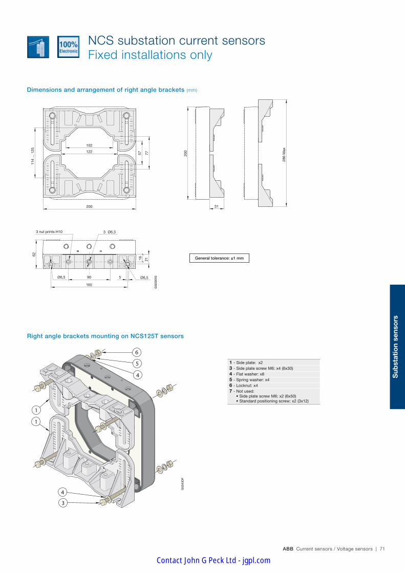
ABB Current sensors / Voltage sensors | 71
Sub
stat
ion
sens
ors
NCS substation current sensors Fixed installations only
Dimensions and arrangement of right angle brackets (mm)
50% 60%
Kit125_3E_p27 et p62 26/10/05
6
5
4
3
4
1
1
G02
43D
F
6
5
4
3
4
1
1
6
5
4
3
4
1
1
Right angle brackets mounting on NCS125T sensors
102
122
200
57
165
77
114
... 1
25
90
200
31
286
Max
Ø6,5 Ø6,5
16 21
62
3 nut prints H10 3 Ø6,3
5
G02
32D
G Kit 125_3 19/10/05
102
122
200
57
165
77
114
... 1
25
90
200
31
286
Max
Ø6,5 Ø6,5
16 21
62
3 nut prints H10 3 Ø6,3
5
G02
32D
G Kit 125_3 19/10/05
General tolerance: ±1 mm
102
122
200
57
165
77
114
... 1
25
90
200
31
286
Max
Ø6,5 Ø6,5
16 21
62
3 nut prints H10 3 Ø6,3
5
G02
32D
G Kit 125_3 19/10/05
1 - Side plate: x23 - Side plate screw M6: x4 (6x30)4 - Flat washer: x85 - Spring washer: x46 - Locknut: x47 - Not used: •SideplatescrewM6:x2(6x50) •Standardpositioningscrew:x2(3x12)
Contact John G Peck Ltd - jgpl.com

72 | ABB Current sensors / Voltage sensors
G02
37D
F
FT_NCS 165_câble 19/10/05
R24
24
13
50
187
195
187
195
165
16548,5
240
30
11
240
45°
Ø6,5
32
NCS substation current sensors Fixed installations only
Dimensions (mm)
G02
37D
F
FT_NCS 165_câble 19/10/05
R24
24
13
50
187
195
187
195
165
16548,5
240
30
11
240
45°
Ø6,5
32
NCS165T-AF
General tolerance: ±1 mm
General tolerance: ±1 mm
L = 2000
G02
28D
F
ES2000 05/10/05
Standard NCS165T-AFsensors secondary connection
AF range wires identification:
1 : Red: +VA (+24V DC)
2 : Black: 0V
3 : Blue: -VA (-24V DC)
4 : NC:
5 : NC:
6 : Green: IS1 (±20mA @ IPN)
7 : White: IS2 (±20mA @ IPMAX)
8 : Brown: 0V
Shielding: see page 108
Shielded cable with braided earth:
L = 2000
G02
28D
F
ES2000 05/10/05
Standard NCS165T-VFsensors secondary connection
VF range wires identification:
1 : Red: +VA (+24V DC)
2 : Black: 0V
3 : Blue: -VA (-24V DC)
4 : Green: VS1 (±10V @ IPN)
5 : White: VS2 (±10V @ IPMAX)
6 : NC:
7 : NC:
8 : Brown: 0V
Shielding: see page 108
Shielded cable with braided earth:
NCS165T-VF
Contact John G Peck Ltd - jgpl.com

ABB Current sensors / Voltage sensors | 73
Sub
stat
ion
sens
ors
NCS substation current sensors Fixed installations only
Dimensions and arrangement of right angle brackets (mm)
50% 60%
12
2
6
5
4
4
4
5
6
3
1
Kit165_1E_p29 et p63 26/10/05
12
2
6
5
4
4
4
5
6
3
G02
44D
F
1
12
2
6
5
4
4
4
5
6
3
1
Right angle brackets mounting on NCS165T sensors
axis
72
2005
5
Ø6,5
6,5
6,5
Ø6,5
62
90
Ø6,3
240
132
165
152
113
90142
122
102
10
10
10
49,5
92
46
80
362 screws 3x122 screws M6x50
240
...
252
(sta
ndar
d)
300
Max
i
180
Max
i
G02
33D
G
Kit 165_1 20/10/05
axis
72
2005
5
Ø6,5
6,5
6,5
Ø6,5
62
90
Ø6,3
240
132
165
152
113
90
142
122
10210
10
10
49,5
92
46
80
36
2 screws 3x122 screws M6x50
240
...
252
(sta
ndar
d)
300
Max
i
180
Max
i
G02
33D
G
Kit 165_1 20/10/05
axis
72
2005
5
Ø6,5
6,5
6,5
Ø6,5
62
90
Ø6,3
240
132
165
152
113
90
142
122
102
10
10
10
49,5
92
46
8036
2 screws 3x122 screws M6x50
240
...
252
(sta
ndar
d)
300
Max
i
180
Max
i
G02
33D
G
Kit 165_1 20/10/05
axis
72
2005
5
Ø6,5
6,5
6,5
Ø6,5
62
90
Ø6,3
240
132
165
152
113
90
142
122
102
10
10
10
49,5
92
46
80
36
2 screws 3x122 screws M6x50
240
...
252
(sta
ndar
d)
300
Max
i
180
Max
i
G02
33D
G
Kit 165_1 20/10/05General tolerance: ±1 mm
1 - Side plate: x22 - Standard positioning screw: x2 (3x12)3 - Side plate screw M6: x2 (6x50)4 - Flat washer: x45 - Spring washer: x26 - Locknut: x27 - Not used: •SideplatescrewM6:x4(6x30) •Flatwasher:x4 •Springwasher:x2 •Locknut:x2
Contact John G Peck Ltd - jgpl.com

74 | ABB Current sensors / Voltage sensors
NCS substation current sensors Fixed installations only
Dimensions and arrangement of right angle brackets (mm)
165
165
16 21
Ø6,3Ø6,5
8
31
62
8 m
ini
154
Max
i
380
Max
i
102
122162 24
0G
0234
DF
Kit 165_2 20/10/05
240
200
90
165
165
16 21
Ø6,3Ø6,5
8
31
62
8 m
ini
154
Max
i
380
Max
i
102
122162 24
0G
0234
DF
Kit 165_2 20/10/05
240
200
90
165
165
16 21
Ø6,3Ø6,5
8
31
62
8 m
ini
154
Max
i
380
Max
i
102
122162 24
0G
0234
DF
Kit 165_2 20/10/05
240
200
90
40%60%
Kit165_2E_p30 et p64 26/10/05
4
5
6
3
4
1
1
G02
45D
F
A
4
5
6
3
4
1
1
A
4
5
6
3
4
1
1
A
Right angle brackets mounting on NCS165T sensors
General tolerance: ±1 mm
1 - Side plate: x23 - Side plate screw M6: x4 (6x30)4 - Flat washer: x85 - Spring washer: x46 - Locknut: x47 - Not used: •SideplatescrewM6:x2(6x50) •Standardpositioningscrew:x2(3x12)
A - The screws for clamping the side plates to the bar (or cable) are not supplied
Contact John G Peck Ltd - jgpl.com

ABB Current sensors / Voltage sensors | 75
Sub
stat
ion
sens
ors
NCS substation current sensors Fixed installations only
Dimensions and arrangement of right angle brackets (mm)
50%60%
Kit165_3E_p31 et p65 26/10/05
5
4
1
1
6
3
4
G02
46D
F
5
4
1
1
6
3
4
5
4
1
1
6
3
4
Right angle brackets mounting on NCS165T sensors
102
122
142
152
49 ..
. 72
69 ..
. 92
89 ..
. 112
109
... 1
32
130
... 1
6562
21
360
Max
240
16
90
200
5
31240
Ø6,5 Ø6,5
3 Ø6,33 nut prints H10
G02
35D
G
Kit 165_3 20/10/05
102
122
142
152
49 ..
. 72
69 ..
. 92
89 ..
. 112
109
... 1
32
130
... 1
6562
21
360
Max
240
16
90
200
5
31240
Ø6,5 Ø6,5
3 Ø6,33 nut prints H10
G02
35D
G
Kit 165_3 20/10/05General tolerance: ±1 mm
102
122
142
15249
... 7
2
69 ..
. 92
89 ..
. 112
109
... 1
32
130
... 1
6562
21
360
Max
240
16
90
200
5
31240
Ø6,5 Ø6,5
3 Ø6,33 nut prints H10
G02
35D
G
Kit 165_3 20/10/05
1 - Side plate: x23 - Side plate screw M6: x4 (6x30)4 - Flat washer: x85 - Spring washer: x46 - Locknut: x47 - Not used: •SideplatescrewM6:x2(6x50) •Standardpositioningscrew:x2(3x12)
Contact John G Peck Ltd - jgpl.com

76 | ABB Current sensors / Voltage sensors
113
mm
100 mm
81 mm
44 mm
The efficient way
Once again ABB have shown that they put all their know-how and talent for innovation into improving efficiency. Whether fitted horizontally or vertically, ABB sensors fit perfectly into your system configurations and the space available. Installa-tion is no longer a problem; in fact inserting sensors is child's play. This choice of fittings is a first in the sensors market. This ability to stay a length ahead makes ABB stand out from their competitors.
The best way up is the way you want
Incomparable modularity
CS current sensors come with a complete range of options and accessories and a wealth of preset variants that have now become standard. As well as being renowned for their in-comparable modularity, CS sensors give their users the edge because they are compact and easy to fit. They also offer a number of connection options, their simplicity and perfor-mance characteristics are unrivalled as are their magnetic im-munity and mechanical resistance. They meet all the exacting demands of sectors as varied as railways, the mining industry and control in difficult environments such as ozone genera-tors. CS current sensors and VS voltage sensors together constitute an offer the railway industry cannot afford to ignore.
Traction current sensors CS range
You simply can't get any smaller!
ABB current sensors contain everything needed to do the job – you don't need anything else. By integrating the philosophy of reduced size into its CS sensors, ABB have brought minia-turization to a point of perfection. This miniaturization also gives great flexibility of installation as well as the best size and performance for money on the market. Small really is beautiful.
Contact John G Peck Ltd - jgpl.com

ABB Current sensors / Voltage sensors | 77
Trac
tio
n se
nso
rs
Unbeatable lifetime
Designed using the 6 sigma approach, the CS range is a model of reliability. The choice and number of optimized com-ponents, traceability of subassemblies, individually production tests… nothing is left to chance to guarantee your peace of mind.
Perfect efficiency in every environment
The CS range has been designed for applications in difficult environments such as on-board railway equipment (power converters, auxiliary converters for heating, ventilation and air conditioning) and the mining industry. Their robust design and excellent performances (e.g. operating range between –40° and +85°C) make CS current sensors ideal for use in other very demanding applications (marine, wind-power, ozone generators, etc.)
Incomparable protection against magnetic fields
CS sensors are conceived, designed and renowned for their unrivalled immunity to ambient magnetic fields. Although they are in continuous proximity of powerful currents capable of distorting their measurements, this does not, in fact, occur. Their accuracy is rock-solid and once set to measure a par-ticular current, that is what they measure – that and nothing else.
BECAUSE YOU WANT RELIABILITY, WE DESIGN FOR LONGEVITY
Quality that goes beyond standards
ABB have been ISO 9001 certified since 1993 and our sen-sors bear the CE label. This ongoing striving after quality has always been the hallmark of a company where excellence and safety are part of the culture, from design right through to production. This culture is the result of continuous research to make technical progress and meet our customers' demands.
CS sensors meet the various security standards in force such as EN 50124-1 for electrical insulation and NFF 16101-NFF 16102 for fire-smoke resistance.
The chief selling-point of CS sensors is their quality. Compliance with EN 50121-X for electromagnetic disturbance and EN 50155 for their high-tech electronic design is proof of their ability to comply with the most detailed constraints as well as major demands. The fact that each indi-vidual sensor is subjected to rigorous testing such as sensor burn-in is proof of the importance ABB attribute to quality.
ABB have long been con-cerned with the protection of the environment, as proved by the ISO 14001 certification they received in 1998. This envi-ronmental approach is particularly noticeable in production of the CS range in the reduction of the number of components, in the use of a low-energy manufacturing procedure and the use of recyclable packing. The products in use are also char-acterized by their reduced energy consumption.
Quality
Security
Environment-friendly
Contact John G Peck Ltd - jgpl.com

78 | ABB Current sensors / Voltage sensors
General data – Plastic case and insulating resin are self-extinguishing. – Fixing holes in the case moulding for horizontal or vertical mounting, with side plates.
– Direction of the current: A primary current flowing in the direction of the arrow results in a positive secondary output current from terminal M.
– Internal electrostatic screen: All CS sensors have an electrostatic screen, this is connected to the screen terminal "E". Depending on the version, when this screen terminal "E" is not provided, the screen is connected to the (–) terminal of the sensor.
UtilisationSensors to measure DC, AC or pulsating currents with a galvanic insulation between primary and secondary circuits.
CS traction current sensorsRolling stock and fixed installations
CS300 / CS503 / CS500
Technical dataHorizontal mounting CS300BR CS503BR CS500BR
Vertical mounting CS300BRV – CS500BRVhorizontal + Screen CS300BRE CS503BRE CS500BRE
vertical + Screen CS300BRVE – CS500BRVENominal primary current A r.m.s. 300 500 500Measuring range @ ±15V (±5%) A peak ±600 – –Measuring range @ ±24V (±5%) A peak ±600 ±750 ±1000Not measurable overload 10ms/hour A peak 3000 5000 5000Max. measuring resistance @ IPMAX & ±15V (±5%) Ω 12 – –Max. measuring resistance @ IPMAX & ±24V (±5%) Ω 40 6 37Min. measuring resistance @ IPN & ±15V (±5%) Ω 0 – –Min. measuring resistance @ IPN & ±24V (±5%) Ω 35 0 0Turn number 2000 3500 5000Secondary current at IPN mA 150 142.86 100Accuracy at IPN @ +25°C % ≤±0.5 ≤±0.5 ≤±0.5Accuracy at IPN -40 … +85°C % ≤±1 ≤±1 ≤±1Offset current @ +25°C & ±24V (±5%) mA ≤±0.5 ≤±0.3 ≤±0.25Linearity % ≤0.1 ≤0.1 ≤0.1Thermal drift coefficient -40 … +85°C µA/°C ≤7.5 ≤7 ≤5Delay time µs ≤1 ≤1 ≤1di/dt correctly followed A / µs ≤100 ≤100 ≤100Bandwidth -1dB kHz ≤100 ≤100 ≤100Max. no-load consumption current @ ±24V (±5%) mA ≤15 ≤15 ≤15Secondary resistance @ +85°C Ω ≤27 ≤88 ≤64Dielectric strength Primary/Secondary (or Primary/(Secondary+Screen) if relevant)
50 Hz, 1 min kV 6.5 6.5 12
Dielectric strength Secondary/Screen (if relevant)
50 Hz, 1 min kV 0.5 0.5 0.5
Supply voltage ±5% V DC ±15 … ±24 ±15 … ±24 ±15 … ±24Voltage drop V ≤2.5 ≤2.5 ≤2.5Mass kg 0.36 0.36 0.78Mass with side plates kg 0.45 0.45 0.95Operating temperature °C -40 …+85 -40 …+85 -40 …+85Storage temperature °C -50 … +90 -50 … +90 -50 … +90
– Protections: - of the measuring circuit against short-circuits. - of the measuring circuit against opening. - of the power supply against polarity reversal.
– Burn-in test in accordance with FPTC 404304 cycle.
Primary connectionHole for primary conductor. The temperature of the primary conductor in contact with the case must not exceed 100°C.
Contact John G Peck Ltd - jgpl.com
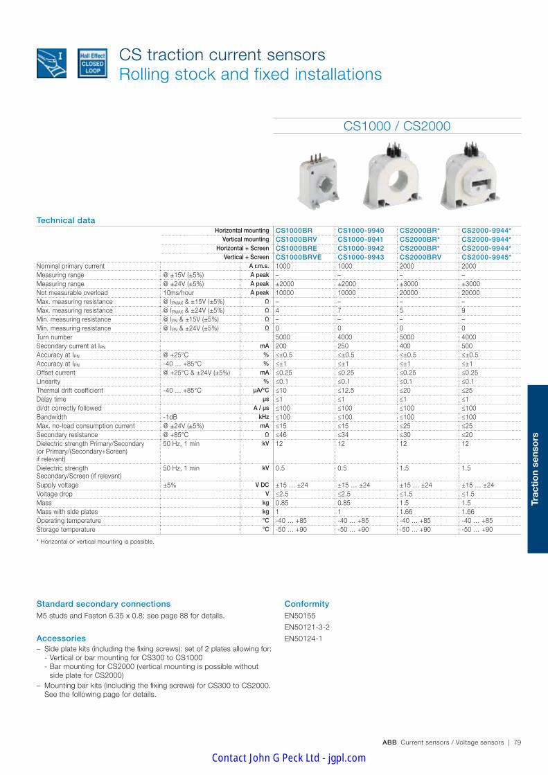
ABB Current sensors / Voltage sensors | 79
Trac
tio
n se
nso
rs
CS1000 / CS2000
Technical dataHorizontal mounting CS1000BR CS1000-9940 CS2000BR* CS2000-9944*
Vertical mounting CS1000BRV CS1000-9941 CS2000BR* CS2000-9944*Horizontal + Screen CS1000BRE CS1000-9942 CS2000BR* CS2000-9944*
Vertical + Screen CS1000BRVE CS1000-9943 CS2000BRV CS2000-9945*Nominal primary current A r.m.s. 1000 1000 2000 2000Measuring range @ ±15V (±5%) A peak – – – –Measuring range @ ±24V (±5%) A peak ±2000 ±2000 ±3000 ±3000Not measurable overload 10ms/hour A peak 10000 10000 20000 20000Max. measuring resistance @ IPMAX & ±15V (±5%) Ω – – – –Max. measuring resistance @ IPMAX & ±24V (±5%) Ω 4 7 5 9Min. measuring resistance @ IPN & ±15V (±5%) Ω – – – –Min. measuring resistance @ IPN & ±24V (±5%) Ω 0 0 0 0Turn number 5000 4000 5000 4000Secondary current at IPN mA 200 250 400 500Accuracy at IPN @ +25°C % ≤±0.5 ≤±0.5 ≤±0.5 ≤±0.5Accuracy at IPN -40 … +85°C % ≤±1 ≤±1 ≤±1 ≤±1Offset current @ +25°C & ±24V (±5%) mA ≤0.25 ≤0.25 ≤0.25 ≤0.25Linearity % ≤0.1 ≤0.1 ≤0.1 ≤0.1Thermal drift coefficient -40 … +85°C µA/°C ≤10 ≤12.5 ≤20 ≤25Delay time µs ≤1 ≤1 ≤1 ≤1di/dt correctly followed A / µs ≤100 ≤100 ≤100 ≤100Bandwidth -1dB kHz ≤100 ≤100 ≤100 ≤100Max. no-load consumption current @ ±24V (±5%) mA ≤15 ≤15 ≤25 ≤25Secondary resistance @ +85°C Ω ≤46 ≤34 ≤30 ≤20Dielectric strength Primary/Secondary (or Primary/(Secondary+Screen)if relevant)
50 Hz, 1 min kV 12 12 12 12
Dielectric strength Secondary/Screen (if relevant)
50 Hz, 1 min kV 0.5 0.5 1.5 1.5
Supply voltage ±5% V DC ±15 … ±24 ±15 … ±24 ±15 … ±24 ±15 … ±24Voltage drop V ≤2.5 ≤2.5 ≤1.5 ≤1.5Mass kg 0.85 0.85 1.5 1.5Mass with side plates kg 1 1 1.66 1.66Operating temperature °C -40 … +85 -40 … +85 -40 … +85 -40 … +85Storage temperature °C -50 … +90 -50 … +90 -50 … +90 -50 … +90
* Horizontal or vertical mounting is possible.
CS traction current sensorsRolling stock and fixed installations
Standard secondary connectionsM5 studs and Faston 6.35 x 0.8: see page 88 for details.
Accessories – Side plate kits (including the fixing screws): set of 2 plates allowing for:
- Vertical or bar mounting for CS300 to CS1000 - Bar mounting for CS2000 (vertical mounting is possible without side plate for CS2000)
– Mounting bar kits (including the fixing screws) for CS300 to CS2000. See the following page for details.
ConformityEN50155
EN50121-3-2
EN50124-1
Contact John G Peck Ltd - jgpl.com

80 | ABB Current sensors / Voltage sensors
Type Sensor concerned Technical description Order code
of the bar
Bar kit CST0 CS300 & CS503 6x25x155 mm², 0.280 kg 1SBT170000R2003
Bar kit CST1-6 CS500 & CS1000 6x40x185 mm², 0.510 kg 1SBT170000R2004
Bar kit CST1-10 CS500 & CS1000 10x40x185 mm², 0.760 kg 1SBT170000R2005
Bar kit CST1 special CS500 & CS1000 10x40x210 mm², 0.8 kg(for compatibility withTA600, TA800 et EA1000 sensors)
1SBT170000R2010
Bar kit CST2 CS2000 20x60x240 mm², 2.5 kg 1SBT170000R2008
Bar kit CST2 special CS2000 20x60x370 mm², 3.8 kg(for compatibility withEA2000 sensors)
1SBT170000R2012
For other bar dimensions: Please contact us for details.
Type Sensor concerned Technical description Order code
Side plate kit CST0 CS300 & CS503 set of 2 plates 1SBT170000R2001
Side plate kit CST1 CS500 & CS1000 set of 2 plates 1SBT170000R2002
Side plate kit CST2 CS2000 set of 2 plates 1SBT170000R2007
AccessoriesSide plates: Side plate kits include all the necessary screws for fixing the plates to the sensor.
OptionsThe main available options are shown below.Other options are possible: Please contact us for details.
Secondary connection:Sensor CS300 & CS503 CS500 & CS1000 CS2000
Secondary connection – – 3 M5 studs
3 M5 inserts 3 M5 inserts 3 M5 inserts
4 M5 inserts 4 M5 inserts 4 M5 inserts
3 pin Lemo connector 3 pin Lemo connector 3 pin Lemo connector
4 pin Lemo connector 4 pin Lemo connector 4 pin Lemo connector
Shielded cable (2 m) Shielded cable (2 m) Shielded cable (2 m)
Number of secondary turns Ns:Sensor CS300 CS503 CS500
Ns 1000 4000 3500
2500 5000
Bar kits:Bar kits include all the necessary screws for mounting the bar on the sensor (the sensor must already be fitted with side plates prior to mounting the bar).
Accessories and options for CS sensors Rolling stock and fixed installations
Contact John G Peck Ltd - jgpl.com

ABB Current sensors / Voltage sensors | 81
Trac
tio
n se
nso
rs
15.215.2
EM+ –
3 x M5
ø 27.5
4 x ø 5.5
6020
12.7
13
84
101
31
33
86
70
3 Faston 6.35 x 0.8 G01
74D
3 x M5
4 x ø 5.5
EM+ –
3 Faston 6.35 x 0.8
19
44
12
100
78
126
113
55
15.2 15.2
78
ø 40.8
G01
76D
40
ø 13
145
185
M6 67
640
ø 13
145
185
M6 67
10
3 x M5
EM+ –
15.2 15.2ø 40
12
40
100 81
70
6.5 6.3 3 Faston6.35 x 0.8
66
65
126
113
55
12
37.5
ø 6.5 ø 6.3
G01
77D
25
ø 13
125
155
ø 5.5ø 6.3
M6 55
6
3 x M5
ø 26
15.215.2
10
2686
64
5852
31
84
101
13
70
5.5 6.3
28.2
46
3 Faston6.35 x 0.8
EM+ –
G01
75D
Size 0 - CS300BRV Bar CST0
Size 1 - CS500BRV and CS1000BRV
The primary bar kit is only available with the vertical mounting versions.Tightening torque for M5 terminal studs (N.m) : 2
Size 0 - CS300BR and CS503BR
Size 1 - CS500BR and CS1000BR
Bar CST1-10
Dimensions (mm)
Horizontal mounting
Horizontal mounting
Bar CST1-6
General tolerance: ±1 mm
General tolerance: ±1 mm
CS traction current sensorsRolling stock and fixed installations
Vertical mounting
Vertical mounting
Contact John G Peck Ltd - jgpl.com

82 | ABB Current sensors / Voltage sensors
CS traction current sensorsRolling stock and fixed installations
20.5
102
37
10
G01
79D
20.6
61
102
20.6
61
20.5
102
37
10
G01
82D
61
102
20.4
3011
135
152
170
3
E –M+
G01
78D
8 x ø 6.5 4 x M5
30
135
88
152
170
E –M+
G01
83D
8 x ø 6.54 x M5 ø 6.5
110
2014
4
136
68.5
4
52
G01
80D
2014
4
136
68.5
4
52
G01
84D
Size 2 - CS2000BR
Size 2 - CS2000BRV
Dimensions (mm)
Horizontal and vertical mounting
Horizontal and vertical mounting60
ø17
190
240
ø8.5 86
20
G02
06D
Bar CST2
60
ø17
190 6060
370
ø8.5 86
20G
0207
D
Bar CST2 special
General tolerance: ±1 mm
General tolerance: ±1 mm
Contact John G Peck Ltd - jgpl.com

ABB Current sensors / Voltage sensors | 83
Trac
tio
n se
nso
rs
Notes
Contact John G Peck Ltd - jgpl.com

84 | ABB Current sensors / Voltage sensors
Traction current sensors TYA range
BECAUSE YOU SEARCH FOR PERFORMANCE WE MAKE THE DIFFERENCE
The resin concept: a reference that has become a standard
Since obtaining ISO 14001 certification in 1998 ABB has integrated an essential concept into its TYA current sensors: a determination to anticipate markets requirements and genuine concern for the protection of the environment. This funda-mental concern is the overwhelming culture that permeates the company. No wonder our competitors are jealous and find our approach an inspiration for their own efforts. With the introduction of recyclable resin, ABB where trailblazers of an innovation that has over the years become a touchstone. It was this concept that enabled ABB to obtain ISO 14001 certification for their concern for the environment. Optimized settings, waste control, minimization of losses, etc. are all factors that again ensure ABB pride of place in the field of current sensors.
A single size for two ratings
With a single size for two ratings (from 300 A to 500 A), TYA current sensors give you the possibility of increasing equip-ment standardization.
Quality that goes beyond standards
ABB have been ISO 9001 certified since 1993 and our TYA range of sensors bears the CE label in Europe. This outgoing striving after quality has always been the hallmark of a com-pany where excellence and safety are part of the culture, from design right through to production. This culture is the result of continuous research to make technical progress and meet our customers' demands.
The chief selling point of TYA sensor is their quality. Compliance with standard EN 50121–X for elec-tromagnetic disturbance and EN 50155 for their high-tech electronic is proof of their ability to comply with the most detailed constraint as well as major demands. The fact that each individual sensor is subjected to rigorous testing is proof of the importance ABB attribute to quality.
ABB have long been concerned with the protection of the environment, as provided by the ISO 14001 certification they received in 1988. This environmental ap-proach is particularly noticeable in production of TYA range in the reduction of the number of components, in the use of a low-energy manufacturing procedure and the use of recy-clable packing. The products in use are also characterized by their reduced energy consumption.
Quality
Ecology
TYA sensors meet the various security stan-dards in force such as EN 50124-1 for electrical insulation and NFF 16101-NFF 16102.
Security
Contact John G Peck Ltd - jgpl.com

ABB Current sensors / Voltage sensors | 85
Trac
tio
n se
nso
rs
TYA traction current sensors
UtilisationSensors to measure DC, AC or pulsating currents with a galvanic insulation between primary and secondary circuits.
ConformityEN50155, EN50124-1, EN50121-3-2
ETL file 4005175
General data – Plastic case and insulation resin are self-extinguishing. – Fixing holes in the case moulding for vertical mounting. – Direction of the current: a primary current flowing in the direction of the arrow results in a positive secondary output current from terminal M.
Primary connectionRectangular hole for primary conductor.
The temperature of the primary conductor in contact with the case must not exceed 100°C.
Secondary connectionMolex type serie ref. 70543-0003
TYA300 / TYA500
Technical dataTYA300-T1521 TYA300-T2423 TYA500-T1545 TYA500-T2447
Nominal primary current A r.m.s. 300 300 400 500Measuring range @ ±15V (±5%) A peak ±600 – ±650 –Measuring range @ ±24V (±5%) A peak – ±450 – ±800Not measurable overload 10msec/hour A peak ≤ ±3000 ≤ ±3000 ≤ ±5000 ≤ ±5000Max. measuring resistance @IPMAX & ±15V (±5%) Ω 10 – 13 –Max. measuring resistance @IPMAX & ±24V (±5%) Ω – 62 40Min. measuring resistance @IPN & ±15V (±5%) Ω 0 – 0 –Min. measuring resistance @IPN & ±24V (±5%) Ω – 61 – 26Turn number 1/2000 1/2000 1/4000 1/4000Secondary current (IS) at IPN mA 150 150 100 125Accuracy at IPN Without offset % ≤ ±0.5 ≤ ±0.5 ≤ ±0.5 ≤ ±0.5Offset current (ISO) Typical value mA ≤ ±0.5 ≤ ±0.5 ≤ ±0.25 ≤ ±0.25Linearity % ≤ ±0.1 ≤ ±0.1 ≤ ±0.1 ≤ ±0.1Thermal drift coefficient +25°C….+85°C µA/°C ≤ 11 ≤ 11 ≤ 5 ≤ 5Thermal drift coefficient -40°C….+25°C µA/°C ≤ 27 ≤ 27 ≤ 14 ≤ 14Delay time µs ≤ 1 ≤ 1 ≤ 1 ≤ 1di/dt correctly followed A/µs ≤ 50 ≤ 50 ≤ 50 ≤ 50Bandwidth -3dB kHz ≤ 50 ≤ 50 ≤ 50 ≤ 50No-load consumption current (IAO) @IP = 0 mA ≤ 25 ≤ 25 ≤ 25 ≤ 25Secondary resistance (RS) @+85°C Ω ≤ 33 ≤ 33 ≤ 67 ≤ 67Dielectric strength Primary/Secondary 50 Hz, 1 min kV r.m.s. 5.5 5.5 3 3Supply voltage ±5% V DC ±15 ±24 ±15 ±24Voltage drop (e') V DC ≤ 1 ≤ 1 ≤ 1 ≤ 1Mass kg 0.150 0.150 0.170 0.170Operating temperature °C -40…+85 -40…+85 -40…+85 -40…+85Storage temperature °C -40…+90 -40…+90 -40…+90 -40…+90
Contact John G Peck Ltd - jgpl.com

86 | ABB Current sensors / Voltage sensors
TYA300-T1521 / TYA300-T2423 / TYA500-T1545 / TYA500-T2447
TYA traction current sensors
Molex type connector series reference 022041041(with 2.54 mm pitch)
Standard TYA …
sensors secondary connection
Dimensions (mm)
General tolerance : ±1 mm
44.5
26 1.5
1.5
26.
1
56
30
56.
5 13
31.
9
1.5
35
46
12.5
37.5
4.5±0.20 (x4)ø 4.5±0.20 (x4)
Contact John G Peck Ltd - jgpl.com

ABB Current sensors / Voltage sensors | 87
Trac
tio
n se
nso
rs
Notes
Contact John G Peck Ltd - jgpl.com
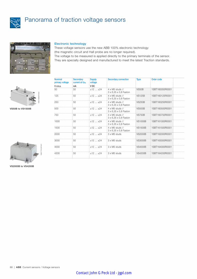
88 | ABB Current sensors / Voltage sensors
VS50B to VS1500B
VS2000B to VS4200B
Nominal primary voltage
Secondary current at UPN
Supply voltage
Secondary connection Type Order code
V r.m.s. mA V DC50 50 ±12 … ±24 4 x M5 studs //
3 x 6,35 x 0,8 FastonVS50B 1SBT160050R0001
125 50 ±12 … ±24 4 x M5 studs // 3 x 6,35 x 0,8 Faston
VS125B 1SBT160125R0001
250 50 ±12 … ±24 4 x M5 studs // 3 x 6,35 x 0,8 Faston
VS250B 1SBT160250R0001
500 50 ±12 … ±24 4 x M5 studs //3 x 6,35 x 0,8 Faston
VS500B 1SBT160500R0001
750 50 ±12 … ±24 4 x M5 studs //3 x 6,35 x 0,8 Faston
VS750B 1SBT160750R0001
1000 50 ±12 … ±24 4 x M5 studs // 3 x 6,35 x 0,8 Faston
VS1000B 1SBT161000R0001
1500 50 ±12 … ±24 4 x M5 studs // 3 x 6,35 x 0,8 Faston
VS1500B 1SBT161500R0001
2000 50 ±12 … ±24 3 x M5 studs VS2000B 1SBT162000R0001
3000 50 ±12 … ±24 3 x M5 studs VS3000B 1SBT163000R0001
4000 50 ±12 … ±24 3 x M5 studs VS4000B 1SBT164000R0001
4200 50 ±12 … ±24 3 x M5 studs VS4200B 1SBT164200R0001
Panorama of traction voltage sensors
These voltage sensors use the new ABB 100% electronic technology(the magnetic circuit and Hall probe are no longer required).The voltage to be measured is applied directly to the primary terminals of the sensor.They are specially designed and manufactured to meet the latest Traction standards.
Electronic technology
1SB
C78
9884
F030
2
1SB
C77
9123
F030
1
Contact John G Peck Ltd - jgpl.com

ABB Current sensors / Voltage sensors | 89
Trac
tio
n se
nso
rs
Panorama of traction voltage sensors
Nominal primary voltage UPN
Secondarycurrent at UPN
Supply voltage
Secondary connection Type Order code
V r.m.s. mA V DC600 50 ±12 … ±24 5 x M5 studs EM010-9239 EM010-9239
750 50 ±12 … ±24 5 x M5 studs EM010-9240 EM010-9240
1000 50 ±12 … ±24 5 x M5 studs EM010-9371 EM010-9371
1500 50 ±12 … ±24 5 x M5 studs EM010-9317 EM010-9317
2000 50 ±12 … ±24 5 x M5 studs EM010-9318 EM010-9318
3000 50 ±12 … ±24 5 x M5 studs EM010-9319 EM010-9319
4200 50 ±12 … ±24 5 x M5 studs EM010-9394 EM010-9394
5000 50 ±12 … ±24 5 x M5 studs EM010-9354 EM010-9354
EM010-9371
Calibrated EM010
Closed loop Hall effect technology also allows for voltage measurement.For calibrated EM010 sensors, the voltage to be measured is applied directly to the primary terminals of the sensor.
Closed loop Hall effect technology1S
BC
7720
43F0
301
Contact John G Peck Ltd - jgpl.com
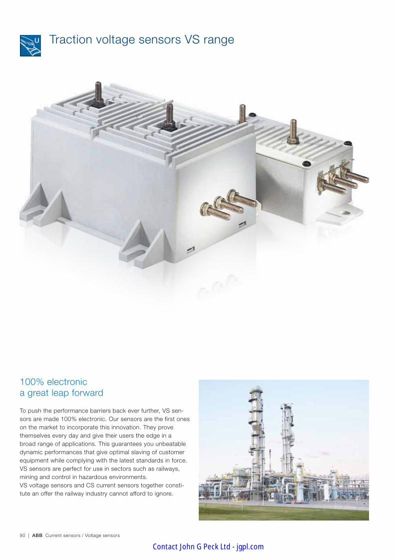
90 | ABB Current sensors / Voltage sensors
Traction voltage sensors VS range
100% electronic a great leap forward
To push the performance barriers back ever further, VS sen-sors are made 100% electronic. Our sensors are the first ones on the market to incorporate this innovation. They prove themselves every day and give their users the edge in a broad range of applications. This guarantees you unbeatable dynamic performances that give optimal slaving of customer equipment while complying with the latest standards in force. VS sensors are perfect for use in sectors such as railways, mining and control in hazardous environments.VS voltage sensors and CS current sensors together consti-tute an offer the railway industry cannot afford to ignore.
Contact John G Peck Ltd - jgpl.com
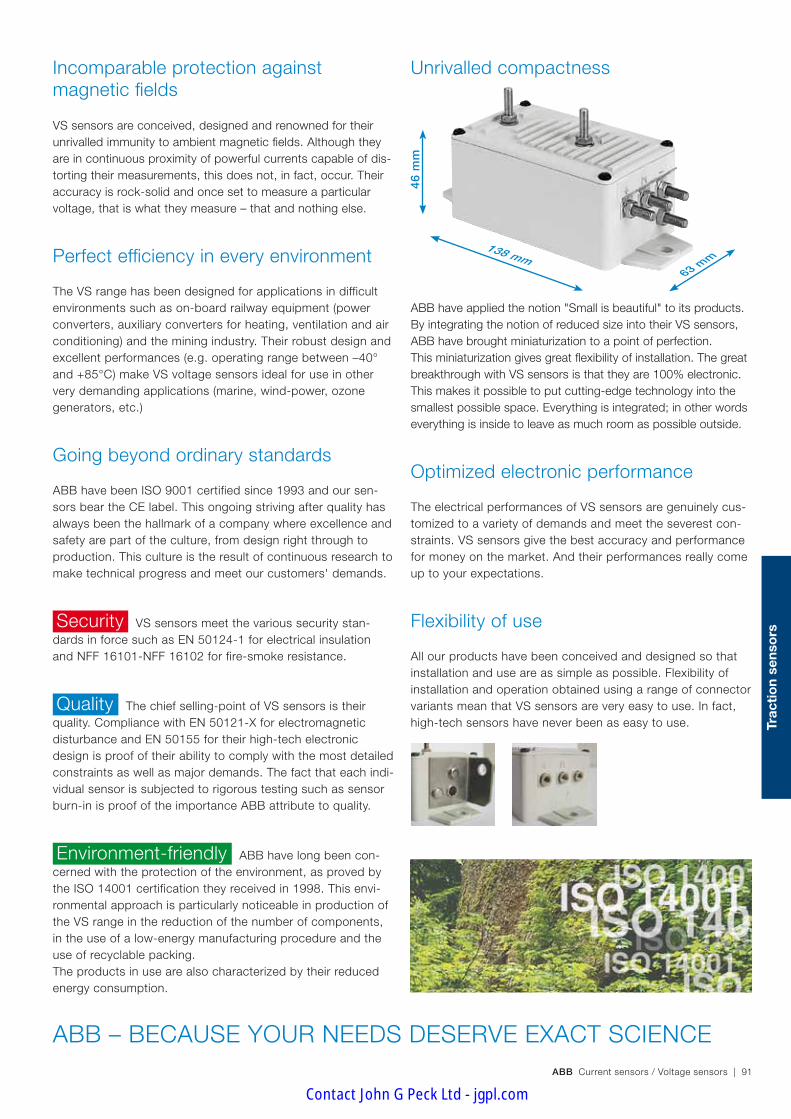
ABB Current sensors / Voltage sensors | 91
Trac
tio
n se
nso
rs
46 m
m
63 mm
138 mm
Going beyond ordinary standards
ABB have been ISO 9001 certified since 1993 and our sen-sors bear the CE label. This ongoing striving after quality has always been the hallmark of a company where excellence and safety are part of the culture, from design right through to production. This culture is the result of continuous research to make technical progress and meet our customers' demands.
VS sensors meet the various security stan-dards in force such as EN 50124-1 for electrical insulation and NFF 16101-NFF 16102 for fire-smoke resistance.
The chief selling-point of VS sensors is their quality. Compliance with EN 50121-X for electromagnetic disturbance and EN 50155 for their high-tech electronic design is proof of their ability to comply with the most detailed constraints as well as major demands. The fact that each indi-vidual sensor is subjected to rigorous testing such as sensor burn-in is proof of the importance ABB attribute to quality.
ABB have long been con-cerned with the protection of the environment, as proved by the ISO 14001 certification they received in 1998. This envi-ronmental approach is particularly noticeable in production of the VS range in the reduction of the number of components, in the use of a low-energy manufacturing procedure and the use of recyclable packing. The products in use are also characterized by their reduced energy consumption.
Incomparable protection against magnetic fields
VS sensors are conceived, designed and renowned for their unrivalled immunity to ambient magnetic fields. Although they are in continuous proximity of powerful currents capable of dis-torting their measurements, this does not, in fact, occur. Their accuracy is rock-solid and once set to measure a particular voltage, that is what they measure – that and nothing else.
Perfect efficiency in every environment
The VS range has been designed for applications in difficult environments such as on-board railway equipment (power converters, auxiliary converters for heating, ventilation and air conditioning) and the mining industry. Their robust design and excellent performances (e.g. operating range between –40° and +85°C) make VS voltage sensors ideal for use in other very demanding applications (marine, wind-power, ozone generators, etc.)
ABB – BECAUSE YOUR NEEDS DESERVE EXACT SCIENCE
ABB have applied the notion "Small is beautiful" to its products. By integrating the notion of reduced size into their VS sensors, ABB have brought miniaturization to a point of perfection.This miniaturization gives great flexibility of installation. The great breakthrough with VS sensors is that they are 100% electronic. This makes it possible to put cutting-edge technology into the smallest possible space. Everything is integrated; in other words everything is inside to leave as much room as possible outside.
Optimized electronic performance
The electrical performances of VS sensors are genuinely cus-tomized to a variety of demands and meet the severest con-straints. VS sensors give the best accuracy and performance for money on the market. And their performances really come up to your expectations.
Flexibility of use
All our products have been conceived and designed so that installation and use are as simple as possible. Flexibility of installation and operation obtained using a range of connector variants mean that VS sensors are very easy to use. In fact, high-tech sensors have never been as easy to use.
Unrivalled compactness
Security
Quality
Environment-friendly
Contact John G Peck Ltd - jgpl.com
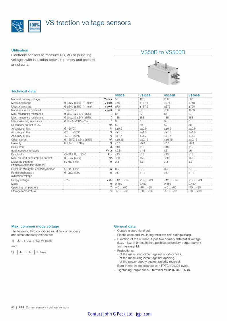
92 | ABB Current sensors / Voltage sensors
VS traction voltage sensors
Max. common mode voltage The following two conditions must be continuously and simultaneously respected:
1) UHT+ + UHT- ≤ 4.2 kV peak
and
2) | UHT+ - UHT- | ≤ UPMAX
UtilisationElectronic sensors to measure DC, AC or pulsating voltages with insulation between primary and second-ary circuits.
VS50B to VS500B
Technical dataVS50B VS125B VS250B VS500B
Nominal primary voltage V r.m.s. 50 125 250 500Measuring range @ ±12V (±5%) / 1 min/h V peak ±75 ±187.5 ±375 ±750Measuring range @ ±24V (±5%) / 1 min/h V peak ±75 ±187.5 ±375 ±750Not measurable overload 1 sec/hour V peak 150 375 750 1500Max. measuring resistance @ UPMAX & ±12V (±5%) Ω 67 67 67 67Max. measuring resistance @ UPMAX & ±24V (±5%) Ω 188 188 188 188Min. measuring resistance @ UPN & ±24V (±5%) Ω 0 0 0 0Secondary current at UPN mA 50 50 50 50Accuracy at UPN @ +25°C % ≤±0.9 ≤±0.9 ≤±0.9 ≤±0.9Accuracy at UPN -25 … +70°C % ≤±1.5 ≤±1.5 ≤±1.5 ≤±1.5Accuracy at UPN -40 … +85°C % ≤±1.7 ≤±1.7 ≤±1.7 ≤±1.7Offset current @ +25°C & ±24V (±5%) mA ≤±0.15 ≤±0.15 ≤±0.15 ≤±0.15Linearity 0.1UPN … 1.5UPN % ≤0.3 ≤0.3 ≤0.3 ≤0.3Delay time µs ≤10 ≤10 ≤10 ≤10dv/dt correctly followed V / µs ≤0.6 ≤1.5 ≤3 ≤6Bandwidth -3 dB & RM = 50 Ω kHz ≤13 ≤13 ≤13 ≤13Max. no-load consumption current @ ±24V (±5%) mA ≤50 ≤50 ≤50 ≤50Dielectric strength Primary/(Secondary+Screen)
50 Hz, 1 min kV 3.3 3.3 3.3 3.3
Dielectric strength Secondary/Screen 50 Hz, 1 min kV 0.5 0.5 0.5 0.5Partial discharges :extinction voltage
@10pC, 50Hz kV ≥1.1 ≥1.1 ≥1.1 ≥1.1
Supply voltage ±5% V DC ±12 … ±24 ±12 … ±24 ±12 … ±24 ±12 … ±24Mass kg 0.450 0.450 0.450 0.450Operating temperature °C -40 …+85 -40 …+85 -40 …+85 -40 …+85Storage temperature °C -50 … +90 -50 … +90 -50 … +90 -50 … +90
General data – Coated electronic circuit. – Plastic case and insulating resin are self-extinguishing. – Direction of the current: A positive primary differential voltage (UHT+ - UHT- > 0) results in a positive secondary output current from terminal M.
– Protections: - of the measuring circuit against short-circuits. - of the measuring circuit against opening. - of the power supply against polarity reversal.
– Burn-in test in accordance with FPTC 404304 cycle. – Tightening torque for M5 terminal studs (N.m): 2 N.m.
Contact John G Peck Ltd - jgpl.com
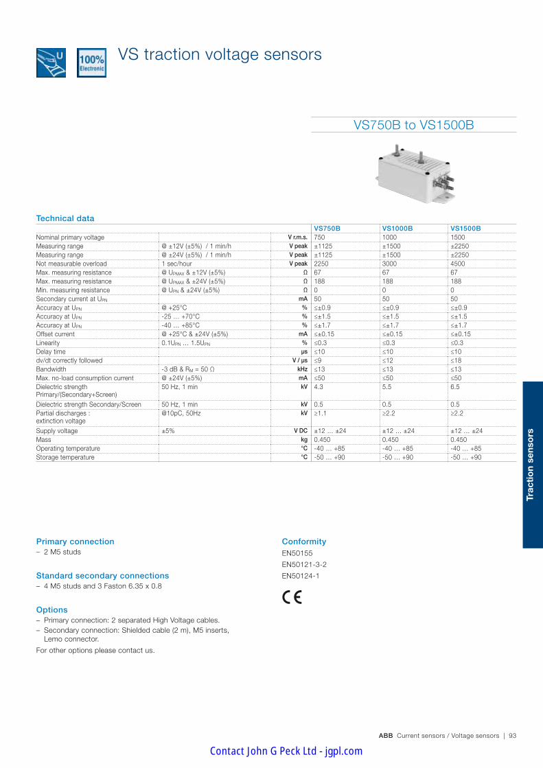
ABB Current sensors / Voltage sensors | 93
Trac
tio
n se
nso
rs
VS traction voltage sensors
VS750B to VS1500B
Technical dataVS750B VS1000B VS1500B
Nominal primary voltage V r.m.s. 750 1000 1500Measuring range @ ±12V (±5%) / 1 min/h V peak ±1125 ±1500 ±2250Measuring range @ ±24V (±5%) / 1 min/h V peak ±1125 ±1500 ±2250Not measurable overload 1 sec/hour V peak 2250 3000 4500Max. measuring resistance @ UPMAX & ±12V (±5%) Ω 67 67 67Max. measuring resistance @ UPMAX & ±24V (±5%) Ω 188 188 188Min. measuring resistance @ UPN & ±24V (±5%) Ω 0 0 0Secondary current at UPN mA 50 50 50Accuracy at UPN @ +25°C % ≤±0.9 ≤±0.9 ≤±0.9Accuracy at UPN -25 … +70°C % ≤±1.5 ≤±1.5 ≤±1.5Accuracy at UPN -40 … +85°C % ≤±1.7 ≤±1.7 ≤±1.7Offset current @ +25°C & ±24V (±5%) mA ≤±0.15 ≤±0.15 ≤±0.15Linearity 0.1UPN … 1.5UPN % ≤0.3 ≤0.3 ≤0.3Delay time µs ≤10 ≤10 ≤10dv/dt correctly followed V / µs ≤9 ≤12 ≤18Bandwidth -3 dB & RM = 50 Ω kHz ≤13 ≤13 ≤13Max. no-load consumption current @ ±24V (±5%) mA ≤50 ≤50 ≤50Dielectric strength Primary/(Secondary+Screen)
50 Hz, 1 min kV 4.3 5.5 6.5
Dielectric strength Secondary/Screen 50 Hz, 1 min kV 0.5 0.5 0.5Partial discharges :extinction voltage
@10pC, 50Hz kV ≥1.1 ≥2.2 ≥2.2
Supply voltage ±5% V DC ±12 … ±24 ±12 … ±24 ±12 … ±24Mass kg 0.450 0.450 0.450Operating temperature °C -40 … +85 -40 … +85 -40 … +85Storage temperature °C -50 … +90 -50 … +90 -50 … +90
Primary connection – 2 M5 studs
Standard secondary connections – 4 M5 studs and 3 Faston 6.35 x 0.8
Options – Primary connection: 2 separated High Voltage cables. – Secondary connection: Shielded cable (2 m), M5 inserts, Lemo connector.
For other options please contact us.
ConformityEN50155
EN50121-3-2
EN50124-1
Contact John G Peck Ltd - jgpl.com
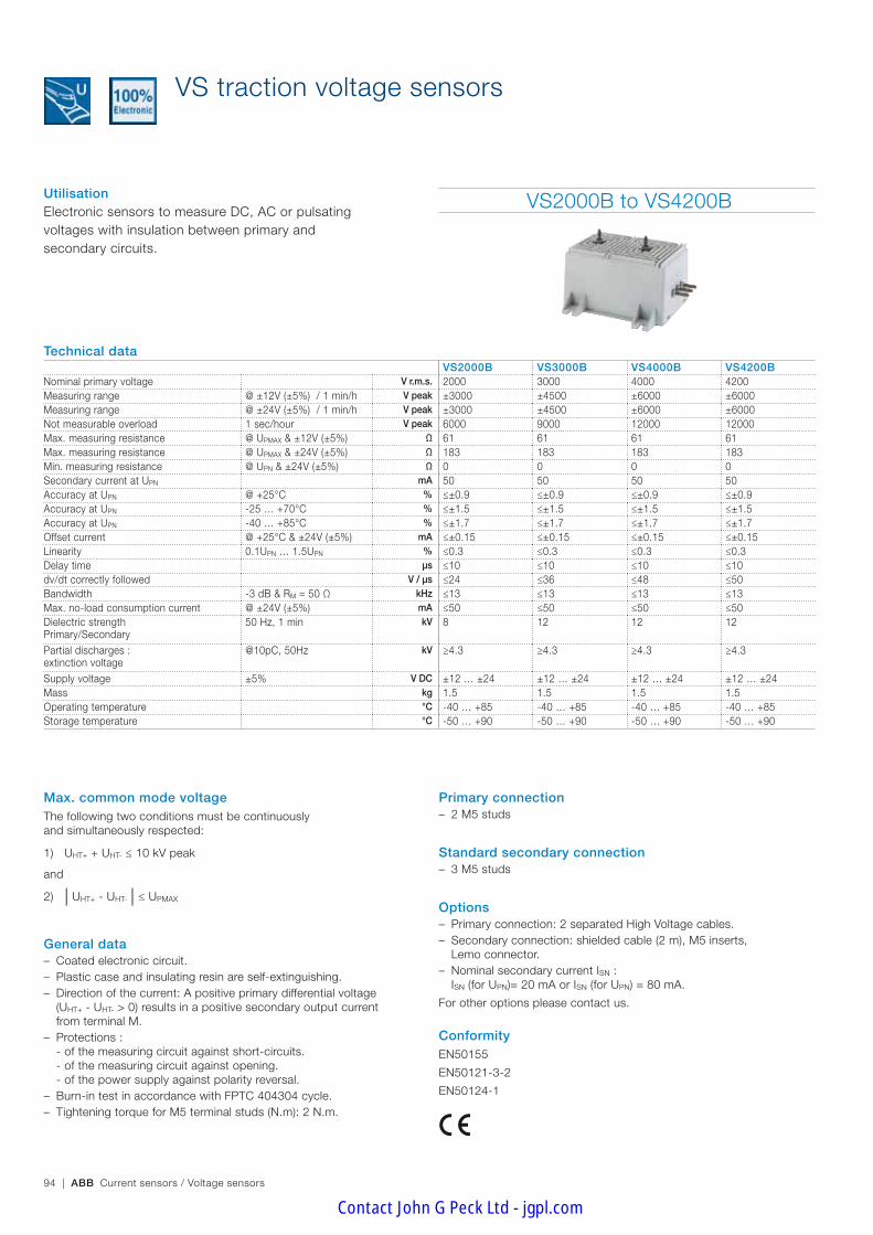
94 | ABB Current sensors / Voltage sensors
VS2000B to VS4200B
Technical dataVS2000B VS3000B VS4000B VS4200B
Nominal primary voltage V r.m.s. 2000 3000 4000 4200Measuring range @ ±12V (±5%) / 1 min/h V peak ±3000 ±4500 ±6000 ±6000Measuring range @ ±24V (±5%) / 1 min/h V peak ±3000 ±4500 ±6000 ±6000Not measurable overload 1 sec/hour V peak 6000 9000 12000 12000Max. measuring resistance @ UPMAX & ±12V (±5%) Ω 61 61 61 61Max. measuring resistance @ UPMAX & ±24V (±5%) Ω 183 183 183 183Min. measuring resistance @ UPN & ±24V (±5%) Ω 0 0 0 0Secondary current at UPN mA 50 50 50 50Accuracy at UPN @ +25°C % ≤±0.9 ≤±0.9 ≤±0.9 ≤±0.9Accuracy at UPN -25 … +70°C % ≤±1.5 ≤±1.5 ≤±1.5 ≤±1.5Accuracy at UPN -40 … +85°C % ≤±1.7 ≤±1.7 ≤±1.7 ≤±1.7Offset current @ +25°C & ±24V (±5%) mA ≤±0.15 ≤±0.15 ≤±0.15 ≤±0.15Linearity 0.1UPN … 1.5UPN % ≤0.3 ≤0.3 ≤0.3 ≤0.3Delay time µs ≤10 ≤10 ≤10 ≤10dv/dt correctly followed V / µs ≤24 ≤36 ≤48 ≤50Bandwidth -3 dB & RM = 50 Ω kHz ≤13 ≤13 ≤13 ≤13Max. no-load consumption current @ ±24V (±5%) mA ≤50 ≤50 ≤50 ≤50Dielectric strength Primary/Secondary
50 Hz, 1 min kV 8 12 12 12
Partial discharges :extinction voltage
@10pC, 50Hz kV ≥4.3 ≥4.3 ≥4.3 ≥4.3
Supply voltage ±5% V DC ±12 … ±24 ±12 … ±24 ±12 … ±24 ±12 … ±24Mass kg 1.5 1.5 1.5 1.5Operating temperature °C -40 … +85 -40 … +85 -40 … +85 -40 … +85Storage temperature °C -50 … +90 -50 … +90 -50 … +90 -50 … +90
VS traction voltage sensors
UtilisationElectronic sensors to measure DC, AC or pulsating voltages with insulation between primary and secondary circuits.
Max. common mode voltage The following two conditions must be continuously and simultaneously respected:
1) UHT+ + UHT- ≤ 10 kV peak
and
2) | UHT+ - UHT- | ≤ UPMAX
General data – Coated electronic circuit. – Plastic case and insulating resin are self-extinguishing. – Direction of the current: A positive primary differential voltage (UHT+ - UHT- > 0) results in a positive secondary output current from terminal M.
– Protections : - of the measuring circuit against short-circuits. - of the measuring circuit against opening. - of the power supply against polarity reversal.
– Burn-in test in accordance with FPTC 404304 cycle. – Tightening torque for M5 terminal studs (N.m): 2 N.m.
Primary connection – 2 M5 studs
Standard secondary connection – 3 M5 studs
Options – Primary connection: 2 separated High Voltage cables. – Secondary connection: shielded cable (2 m), M5 inserts, Lemo connector.
– Nominal secondary current ISN : ISN (for UPN)= 20 mA or ISN (for UPN) = 80 mA.
For other options please contact us.
ConformityEN50155
EN50121-3-2
EN50124-1
Contact John G Peck Ltd - jgpl.com
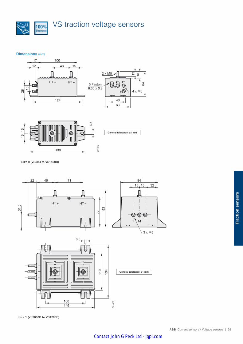
ABB Current sensors / Voltage sensors | 95
Trac
tio
n se
nso
rs
VS traction voltage sensors
M+ –HT + HT –
10017
12 48 15
2 x M5
63
40
4 x M5
3 Faston6.35 x 0.8
1813
64
138
15
6.5
1528
15
124G
0181
D
E
M+ –
HT + HT –
9422 46 71
31.5
77
93
100146
110
134
6.5
321515
3 x M5
G01
67D
Size 1 (VS2000B to VS4200B)
Dimensions (mm)
General tolerance: ±1 mm
General tolerance: ±1 mm
Size 0 (VS50B to VS1500B)
Contact John G Peck Ltd - jgpl.com

96 | ABB Current sensors / Voltage sensors
EM010 from 600 to 1500 V
Technical dataEM010-9239 EM010-9240 EM010-9371 EM010-9317
Nominal primary voltage V r.m.s. 600 750 1000 1500Measuring range 50 s/h @ +70°C V peak ±900 ±1125 ±1500 ±2250Min. measuring resistance @ UPN & ±15V Ω 0 0 0 0Primary turn number 10000 7500 15000 15000Secondary turn number 2000 2000 2000 2000Secondary current at UPN mA 50 50 50 50Accuracy at UPN @ +25°C % ≤±1 ≤±1 ≤±1 ≤±1Offset current @ +25°C mA ≤±0.3 ≤±0.3 ≤±0.3 ≤±0.3Linearity % ≤±0.1 ≤±0.1 ≤±0.1 ≤±0.1Thermal drift coefficient -25 … +70°C µA/°C ≤±5 ≤±5 ≤±5 ≤±5Delay time µs ≤100 ≤100 ≤100 ≤100Max. no-load consumption current @ ±24V mA ≤25 ≤25 ≤25 ≤25Primary resistance @ +25°C k Ω 60 56 150 225Secondary resistance @ +70°C Ω 60 60 60 60Dielectric strength Primary/(Secondary+Screen+Ground)
50 Hz, 1 min kV 6 6 12 12
Dielectric strengthSecondary/(Screen+Ground)
50 Hz, 1 min kV 1 1 1 1
Supply voltage ±10% V DC ±15 … ±24 ±15 … ±24 ±15 … ±24 ±15 … ±24Voltage drop V ≤1.5 ≤1.5 ≤1.5 ≤1.5Mass kg 0.650 0.650 0.650 0.650Operating temperature °C -25 …+70 -25 …+70 -25 …+70 -25 …+70Storage temperature °C -40 …+85 -40 …+85 -40 …+85 40 …+85Primary connections 2 x M5 studs 2 x M5 studs 2 x M5 studs 2 x M5 studsSecondary connections 5 x M5 studs 5 x M5 studs 5 x M5 studs 5 x M5 studs
Calibrated EM010 traction voltage sensors
UtilisationSensors to measure DC or AC voltages with a galvanic insulation between primary and secondary circuits.The input resistor RE is included with calibrated EM010 sensors, the voltage to be measured UP can be applied directly to the primary terminals marked "+HT" and "-HT" (see diagram below).
Diagram
M
+
E
UP
+ HT
– HT
IS
–
R = RE + RP
Calibrated EM010
G01
89D
G
RE
RP
General data – Plastic case and insulating resin are self-extinguishing. – Direction of the current: A positive primary differential voltage (UHT+ - UHT- > 0) results in a positive secondary output current from terminal M.
– The internal electrostatic screen between the primary and secondary is linked to the terminal "E".
– The heatsink for the integrated input resistance RE is connected to the marked earth terminal on the sensor.
– Protection of the power supply against polarity reversal. – Burn-in test in accordance with FPTC 404304 cycle. – Tightening torque for M5 terminal studs (N.m): 2.8 N.m. – The primary resistance R is made up of the integrated input resistance RE in series with the resistance RP of the primary winding: R = RE + RP
Contact John G Peck Ltd - jgpl.com

ABB Current sensors / Voltage sensors | 97
Trac
tio
n se
nso
rs
Calibrated EM010 traction voltage sensors
Options – Other connection types – Other temperature operating ranges.
For other options please contact us.
Conformity
EM010 from 2000 to 5000 V
Technical dataEM010-9318 EM010-9319 EM010-9394 EM010-9354 (1)
Nominal primary voltage V r.m.s. 2000 3000 4200 5000Measuring range 50 s/h @ +70°C V peak ±3000 ±4500 ±8000 (10s/2h) ±8000 (10s/2h)Min. measuring resistance @ UPN & ±15V Ω 0 0 0 0Primary turn number 20000 30000 30000 20000Secondary turn number 2000 2000 1260 1000Secondary current at UPN mA 50 50 50 50Accuracy at UPN @ +25°C % ≤±1 ≤±1 ≤±1 ≤±1Offset current @ +25°C mA ≤±0.3 ≤±0.3 ≤±0.3 ≤±0.3Linearity % ≤±0.1 ≤±0.1 ≤±0.1 ≤±0.1Thermal drift coefficient -25 … +70°C µA/°C ≤±5 ≤±5 ≤±5 ≤±5Delay time µs ≤100 ≤100 ≤100 ≤100Max. no-load consumption current @ ±24V mA ≤25 ≤25 ≤25 ≤25Primary resistance @ +25°C k Ω 400 900 2000 2000Secondary resistance @ +70°C Ω 60 60 25 20Dielectric strength Primary/(Secondary+Screen+Ground)
50 Hz, 1 min kV 12 12 12 12
Dielectric strengthSecondary/(Screen+Ground)
50 Hz, 1 min kV 1 1 1 1
Supply voltage ±10% V DC ±15 … ±24 ±15 … ±24 ±15 … ±24 ±15 … ±24Voltage drop V ≤1.5 ≤1.5 ≤1.5 ≤1.5Mass kg 0.650 0.650 0.650 0.650Operating temperature °C -40 …+75 -40 …+75 -25 …+70 -25 …+70Storage temperature °C -40 …+85 -40 …+85 -45 …+85 -40 …+85Primary connections 2 x M5 studs 2 x M5 studs 2 x M5 studs 2 x M5 studsSecondary connections 5 x M5 studs 5 x M5 studs 5 x M5 studs 5 x M5 studs
(1) No burn-in test applied.
Contact John G Peck Ltd - jgpl.com
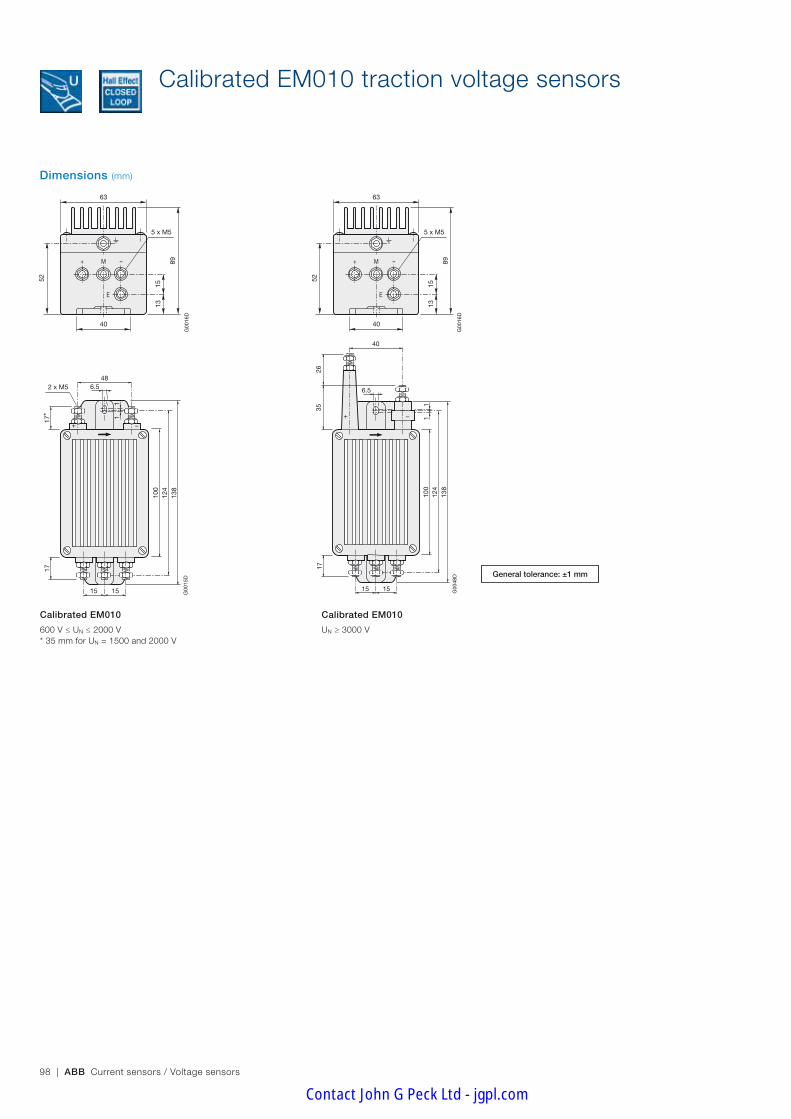
98 | ABB Current sensors / Voltage sensors
Calibrated EM010 traction voltage sensors
Dimensions (mm)
100
124
138
1717
*
6.548
2 x M5
1515
11
+ –
G00
15D
100
124
138
17
6.5
40
1515
11
+ –
2635
G00
48D
Calibrated EM010
600 V ≤ UN ≤ 2000 V* 35 mm for UN = 1500 and 2000 V
Calibrated EM010
UN ≥ 3000 V
89
52
15
40
E
–M+
63
5 x M5
13
G00
16D
89
52
15
40
E
–M+
63
5 x M5
13
G00
16D
General tolerance: ±1 mm
Contact John G Peck Ltd - jgpl.com

ABB Current sensors / Voltage sensors | 99
Trac
tio
n se
nso
rs
Notes
Contact John G Peck Ltd - jgpl.com

100 | ABB Current sensors / Voltage sensors
Maintenance personnel warning: an ABB innovation.
Faced with a current offering with insufficient reliability that doesn't meet the market standards, ABB has innovated with the VD Traction voltage detector. This 100% electronic product allows your maintenance operatives to be aware of the presence of a continuous voltage, before carrying out operations on equipment. When the diode flashes, the voltage is greater than 50V and when it is extinguished, the voltage is below this limit. Provided with a double internal function and
Traction voltage detectors VD range
independent LEDs, the VD Traction voltage detector offers redundant function and a lifetime greater than 1 million hours. Guaranteed for 2 years, it allows reliable decisions to carry out operations to be made and warns personnel from danger-ous high voltages.
Contact John G Peck Ltd - jgpl.com

ABB Current sensors / Voltage sensors | 101
Trac
tio
n se
nso
rs
BECAUSE YOUR SECURITY IS ESSENTIAL
A considered and measured integrated design
Thanks to a 100% electronic technology, ABB has reduced the size of the VD Traction voltage sensor to a minimum. The ultra-compact dimensions allow for simplified installation. Additionally, its self-sufficiency in energy means that it can work without an external power supply.
Quality that goes beyond standards
The new product complies with the standard EN50155 (high technology electronic design and testing) and EMC EN50121-3-2 (electromagnetic compatibility: resistance to electromagnetic interference) and follows a very rigorous manufacturing process.
Certified ISO 9001 and CE labeled, the VD Trac-tion voltage detector complies with the most rigorous stan-dards and requirements.
100% electronic
At the forefront of technological innovation at ABB, the VD Traction voltage detector is 100% electronic. Other than the assurance of providing unbeatable performance, it has reduced dimensions: smaller and more compact, it offers greater installation flexibility.Its 100% electronic technology also provides it with an excel-lent immunity to surrounding magnetic fields: a guarantee for accurate detection of a given voltage.
An answer adapted to market requirements
Guaranteeing optimum reliability, the VD Traction voltage de-tector meets the requirements for difficult environments and is adaptable to the most demanding applications such as: – rolling stock: main converters, auxiliary converters. Based
on the SNCF CF60-100 specification, the whole French railway market imposes the presence of a voltage detector within built redundancy, to meet the drastic requirements of this sector.
– electronic power systems integrating capacitors banks: backups, wind generators, variable speed drives, electroly-sis require voltage detectors of robust design and offer high reliability.
Double lifetime to avoid taking any risks
The VD Traction voltage detector is a voltage detection sys-tem with built in redundancy. It is equipped with two elec-tronic circuits each connected to a light emitting diode (LED). These two parallel and independent systems guarantee a high level of functioning and improve the reliability of the detector.
The VD Traction voltage detector is the only product on the market that complies with rolling stock se-curity standards such as: EN50124-1 (electrical isolation), EN50163 (standardized voltage 1500 V DC).
Reduction of the number of components, low energy manufacturing processes, use of recyclable pack-ing, reduced energy consumption… The VD Traction voltage detector complies with all the requirements of the ISO 14001 environmental standard, in place at ABB since 1998.
Security
Quality
Ecology
Contact John G Peck Ltd - jgpl.com

102 | ABB Current sensors / Voltage sensors
General operation
UOFF : Low limit at which the LEDs extinguish when the equipment is electrically isolated.
UON : High limit at which the LEDs illuminate (flashing frequency ap-proximately 2 Hz) when the equipment power is switched on.
Between these two limits the LEDs maybe extinguished or flashing.
Accessories Product – VD1500-48 order code: 1SBT900000R0007.
LED replacement kit – ABB order code: 1SBT900000R2002 including 5 LEDs with plastic support.
Lens replacement kit (transparent cover) – ABB order code: 1SBT900000R2001 including 10 lenses.
ConformityEN50155, EN50124-1, EN50121-3-2, EN50163
UtilisationElectronic detectors for direct voltages. This device signals the presence of dangerous voltages via the independent flashing of two LEDs (Light emitting diodes). A secondary supply voltage is not necessary.
VD1500
Technical dataVD1500-48
Nominal voltage (UN) V DC 1500Maximum voltage permanent UMAX1 V DC 1800Maximum voltage long duration UMAX2 5 min V DC 1950Maximum voltage overload UMAX3 20 msec/h V DC 2540Insulation voltage rating (1) (UNM) 50 Hz, 10 sec kV 6.5Average current consumption (LED flashing) mA ≤1LED flashing frequency Hz 2Activating voltage UON V DC > 49Activating voltage UOFF V DC < 38Mass Kg ≤0.5Operating temperature °C -25 ... +70Operating and starting temperature °C -40 ... +85Light Emitting Diode (LED) colour redLight Emitting Diode (LED) angle of vision ≤15°
(1) Overload category: 3 (OV3), pollution degree: 2 (PD2)
VD traction voltage detectorsRolling stock and fixed installations
General data – Plastic case and insulating resin are self-extinguishing. – The casing temperature must not exceed 105°C. – Fixing holes in the case moulding for horizontal mounting. – Changing of the 2 LEDs is without tools. – Product mounting according to the document: VD1500 range Mounting Instructions (ref. 1SBC140001M1704).
– Product Use and Maintenance instructions according to the docu-ment: Use of the Voltage Detector - Preventive and Curative Mainte-nance VD1500 Range (ref. 1SBD370058P0004).
– Tightening torque: 2Nm
SecurityOnly qualified and authorised personnel may carry out any operation on the detector; without voltage applied to the terminals of the voltage detector and with the equipment (power converter) electrically isolated.
In order to maintain the high level of lifetime, the 2 LEDs must always be replaced at the same time.
Primary connection – Insert M5x7 for terminals HT1+ and HT2+ – Insert M4x7 for terminals HT1- and HT2-
UOFF UON UN
Udc
38V0V 49V 1500V
LED extinguished LED extinguished or flashing
LED flashing
Contact John G Peck Ltd - jgpl.com

ABB Current sensors / Voltage sensors | 103
Trac
tio
n se
nso
rs
Dimensions (mm)
VD traction voltage detectorsRolling stock and fixed installations
Wiring diagram
General tolerance: ±1 mm
VD1500 05/10/05
HT1+
HT2+
HT1-
HT2-
HT+
HT+
HT-
HT-
UP
UP
Clientequipment
VD1500
LED 1
LED 2
G02
26D
G
VD1500
The two connections HT+ (client equipment side) must be made at different connection points. The two connections HT - (client equipment side) must be made at different connection points.
Contact John G Peck Ltd - jgpl.com

104 | ABB Current sensors / Voltage sensors
IntroductionThese instructions are a non-exhaustive synthesis of the main recommendations for mounting closed loop Hall effect current sensors.
Each application configuration is different, do not hesitate to contact us for advice adapted to your particular case.
Please note that incorrect or non-judicious use of the sensor may lead to deterioration in the performance or operation of the sensor.
1 - Wiring diagram – Direction of the current: A primary current IP flowing in the direction of the arrow results in a positive secondary output current Is from terminal M. – Supply voltage: bipolar voltage -VA… 0V … +VA
Closed loop Hall effect sensors can also operate with a unipolar supply voltage (-VA … 0V or 0V … +VA) under certain conditions.
Please contact your distributor for further details for this application.
1.1 - Sensors without screen terminal
1.2 - Sensors with screen terminal
Recommended wiring Alternative wiring
The screen terminal "E" can be connected to the secondary negative terminal (marked "-") on the sensor. However the best EMC performance is obtained by connecting the screen terminal "E" to ground by a copper braid strap as short as possible.
1.3 - Internal electrostatic screen
During very rapid variations in the primary conductor potential compared to the reference potential (high du/dt), a capacitive coupling effect can be produced between the primary conductor and the secondary winding of the sensor. This coupling can lead to measurement errors. In order to eliminate this capacitive coupling, some current sensors have an internal copper electrostatic screen between the secondary winding and the hole for the primary conductor. This screen is linked internally either to an additional terminal marked "E", or to the sensor negative secondary terminal (marked "-").
2 - Mechanical mounting – All mounting positions are possible: horizontal, vertical, upside down etc. – Recommended fixing: by screws and flat washers. – Installation with a primary bar: in this case, the sensor must be mechanically fixed, either only by the bar, or only by the enclosure, but never by both at the same time (this type of fixing would lead to mechanical stresses that could lead to deterioration of the sensor casing).
3 - Precautions to be taken into account relative to the electromagnetic environmentDue to their operating principle (measure of magnetic field by the Hall effect probe), closed loop Hall effect current sensors can be sensitive to strong external magnetic fields. It is therefore strongly recommended to avoid positioning them too close to high current power cables. The use of a magnetic screen to protect the sensor may be advised for certain configurations with a strong magnetic influence.
The orientation of the sensor is also very important. Please contact your distributor for further information on this subject.
4 - Processing of the sensor's output signalStandard codes of practice advise that, before the signal is processed, a low-pass filter adapted to the bandwidth of the sensor is used. Moreover, in the case of digital processing of the signal, it is also recommended that the sampling frequency is adapted to the bandwidth of both the signal to be measured and the sensor.
In the event of sensor failure, the processing of the output signal should take into account deterioration in performance (e.g. absence of signal or saturated signal) and rapidly and safely shut the system down.
M
+
E
0 V
+ VA
- VA
G01
97D
G
IP
Current sensor Power supply
IS RM
VM-
Closed loop Hall effect current sensorsInstructions for mounting and wiring ES, TYA, MP, EL and CS sensors
M
+IS
IP
–
0 V
+ VA
– VA
G01
96D
G
Current sensor Power supply
RM
VM
M
+
E
–
0 V
+ VA
– VA
G01
98D
GIP
Current sensor Power supply
IS RM
VM
Contact John G Peck Ltd - jgpl.com

ABB Current sensors / Voltage sensors | 105
Co
mm
on
info
rmat
ion
Open loop Hall effect current sensors Instructions for mounting and wiring HBO sensors
IntroductionThese instructions are a non-exhaustive synthesis of the main recommendations for mounting open loop Hall effect current sensors. Each ap-plication configuration is different, please do not hesitate to contact us for advice adapted to your particular case. Please note that incorrect or non-judicious use of the sensor may lead to deterioration in the performance or operation of the sensor.
1 - Wiring diagram – Direction of the current: a primary current IP flowing in the direction of the arrow results in a positive secondary output voltage from the terminal VS. – Supply voltage: bipolar voltage: -VA … 0V … +VA
– Contrary to output current devices, HBO sensors do not need a load resistance but it is possible to use one if required.
2 - Mechanical mounting – All mounting positions are possible: horizontal, vertical, upside down etc. – Recommended fixing: by screws and flat washers.
3 - Precautions to be taken into account relative to the electromagnetic environmentDue to their principle of operation (measure of magnetic field by the Hall effect probe), open loop Hall effect current sensors can be sensitive to strong external magnetic fields. It is therefore strongly recommended to avoid positioning them too close to high current power conductors. The sensor cables (shielded cable recommended) connecting to the equipment should be as short as possible.
These sensors emit almost no electromagnetic radiation but can be sensitive to the effects of external radiation. The sensor is not itself sensitive but the induced voltages, when long cables are used to link the sensor to the connector, can cause interference to the sensor.
In many applications the sensors are mounted in metal housings and have short cable lengths. In these applications, no special precautions are normally required.
In applications that require the sensor is used with long exposed cable lengths, shielded cable must be used, with both ends of the shielding con-nected to ground (see figure below).
4 - Processing of the sensor's output signalStandard codes of practice advise that, before the signal is processed, a low-pass filter adapted to the bandwidth of the sensor is used.
Moreover, in the case of digital processing of the signal, it is also recommended that the sampling frequency is adapted to the bandwidth of both the signal to be measured and the sensor.
In the event of sensor failure, the processing of the output signal should take into account this deterioration in performance (e.g. absence of signal or saturated signal) and rapidly and safely shut the system down.
HBO Instruction de montage et câblage Capteurs - page 93/120
RM
+ VA
Power supplyHBO sensor
G02
17D
G0V
- VA
Is
Vs
0V
- VA
+ VA
Vs
Ip
HBO Instruction de montage et câblage Capteurs - page 93/120
Electronic boardHBO sensor
G02
18D
G
- VA
+ VA
Vs 0 VShielded cable
Ip
- VA
+ VA
0 V 0 V
RM
Contact John G Peck Ltd - jgpl.com
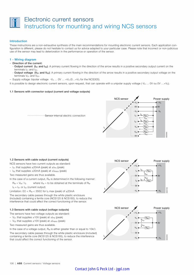
106 | ABB Current sensors / Voltage sensors
IntroductionThese instructions are a non-exhaustive synthesis of the main recommendations for mounting electronic current sensors. Each application con-figuration is different, please do not hesitate to contact us for advice adapted to your particular case. Please note that incorrect or non-judicious use of the sensor may lead to deterioration in the performance or operation of the sensor.
1 - Wiring diagram – Direction of the current:
- Output current (IS1 and IS2): A primary current flowing in the direction of the arrow results in a positive secondary output current on the terminals IS1 and IS2.
- Output voltage (VS1 and VS2): A primary current flowing in the direction of the arrow results in a positive secondary output voltage on the terminals VS1 and VS2.
– Supply voltage: bipolar voltage -VA … 0V … +VA (0…+VA for the NCS305).
It is possible to design electronic current sensors, upon request, that can operate with a unipolar supply voltage (-VA … 0V ou 0V …+VA).
1.1 Sensors with connector output (current and voltage outputs)
Sensor internal electric connection
1.2 Sensors with cable output (current outputs)
NCS sensors have two current outputs as standard: – IS1 that supplies ±20mA (peak) at ±IPN (peak) – IS2 that supplies ±20mA (peak) at ±IPMAX (peak)
Two measured gains are thus available.
In the case of a current output, RM is determined in the following manner:
RM = VM / IS where VM = to be obtained at the terminals of RM
IS = IS1 or IS2 (current output)
Limitation: 0Ω < RM < 350Ω for IS max (peak) of ±20mA
The secondary cable passes through the white plastic enclosure (included) containing a ferrite core (NCS125 & NCS165), to reduce the interference that could affect the correct functioning of the sensor.
1.3 Sensors with cable output (voltage outputs)
The sensors have two voltage outputs as standard: – VS1 that supplies ±10V (peak) at ±IPN (peak) – VS2 that supplies ±10V (peak) at ±IPMAX (peak)
Two measured gains are thus available.
In the case of a voltage output, RM is either greater than or equal to 10kΩ.
The secondary cable passes through the white plastic enclosure (included) containing a ferrite core (NCS125 & NCS165), to reduce the interference that could affect the correct functioning of the sensor.
Electronic current sensorsInstructions for mounting and wiring NCS sensors
NCS - Instruction de montage et câblage Capteurs P94 à 96/120Schéma de câblage NCS_1
Power supplyNCS sensor
G02
20D
GVs2
0V
Is2
Vs1
- VA
Is1
+ VA
0V
IpRM3
RM2
RM1Is1
Is2
- VA
+ VA
0V
VM2
VM1
VM3
RM4
VM4
NCS - Instruction de montage et câblage Capteurs P94 à 96/120Schéma de câblage NCS_2
Power supplyNCS sensor
G02
21D
G
- VA
Is2
0V
Is1
0V
+ VA
Ip
Is1
Is2
+ VA
0V
- VA
RM2
RM1
VM2
VM1
NCS - Instruction de montage et câblage Capteurs P94 à 96/120Schéma de câblage NCS_3
Power supplyNCS sensor
G02
22D
G
- VA
Vs2
0V
Vs1
0V
+ VA
Ip
Vs1
Vs2
+ VA
0V
- VA
RM4
RM3
Contact John G Peck Ltd - jgpl.com

ABB Current sensors / Voltage sensors | 107
Co
mm
on
info
rmat
ion
2 - Mechanical mounting – All mounting positions are possible: horizontal, vertical, upside down etc. – Recommended fixing: by screws and flat washers. Oblong fixing holes in the enclosure moulding provide a large amount of mounting flexibility and allow for fully symmetrical positioning.
– Fixing by the use of side plate kits: - Fixing on one (or several) cable on one (or several) primary bar: in this case, the sensor should only be fixed to the primary conductor mechani-cally by the side plate kit. The sensor must not be mechanically fixed to the primary conductor by the enclosure and the side plate kit at the same time (this type of mounting would lead to mechanical stresses that may deteriorate the enclosure).
- Fixing on a chassis or partition: in this case, the side plate kit offers a large amount of mounting flexibility.
See the particular mounting instructions.
Recommendations for the passage of the primary conductor – The primary conductor may be one (or several) cable or one (or several) bar. – In order to obtain the best measuring performance, the primary conductor must be:
- Centred as much as possible in the opening in the sensor - The biggest possible with respect to the opening in the sensor - Fixed at an angle close to 90° with respect to a plane formed by the sensor - As straight as possible at the sensor in order to minimise local increases in the magnetic field caused by bends in the primary conductor. These local increases may create a saturation of one of the sensor probes and induce measurement errors.
For further information, please refer to the "Dimensions" section of the NCS range in this catalogue (pages 28...38 or pages 68...75) or to the mounting instructions ref. 1SBC146000M1704 (NCS125 & NCS165) or ref. 1SBC146010M1701 (NCS305).
Electronic current sensorsInstructions for mounting and wiring NCS sensors
Contact John G Peck Ltd - jgpl.com

108 | ABB Current sensors / Voltage sensors
3 - Precautions to be taken into account relative to the electromagnetic environmentDue to the continuous reduction in equipment volume and the increase in their power, internal system components are subject to strong electro-magnetic interference. NCS sensors, based on the measure of currents by magnetic fields, (see operating instructions 1SBD370024R1000) must not be interfered by surrounding magnetic fields. They have therefore been designed in order to allow accurate measurement without interference.
Different tests carried out on NCS sensors show the rejection of the sensors to this external magnetic interference in relation to the configuration of the predefined bar arrangement.
During type testing, the sensors were subject to 3 types of tests: – magnetic field circuits: measure the influence of the magnetic fields generated by the primary conductor on the sensor – interference by an external set of bars: measure the influence of the magnetic fields generated by the other conductors different from the pri-mary conductor on the sensor
– coupling of primary bars: measure the influence of the mechanical mounting of the sensor on a primary conductor
During the different tests and in each configuration, the measured results (accuracy) are recorded whilst varying the following elements: - distance between the sensor and the interfering current - rotation of the interfering current around the sensor - the magnitude of the interfering current - the current form (DC or AC) - inclination of the sensor on the primary conductor - centricity of the sensor on the primary bar - different primary bar configurations (rectangular simple or double, round and arrangements in "U", "S" or "L" configurations)
The tests were carried out with the primary bars in "U" configuration, the most restricting condition.
See mounting instructions ref. 1SBC146000M1704 (NCS125 & NCS165) or ref. 1SBC146010M1701 (NCS305) for further information.
3.1 Mounting for improved EMC performance (shielding)
In applications that require the sensor to be used with long cables exposed to interference, it is imperative that shielded cables are used, with the shielding connected to ground at both ends (see figure below).
Standard NCS sensors with cable outputs are supplied in white plastic enclosures containing a ferrite core (NCS125 & NCS165). The secondary cable passes through this white plastic enclosure to reduce the interference caused that could affect the correct functioning of the sensor.
Please contact your distributor for further information on this subject.
4 - Processing of the sensor's output signalStandard codes of practice advise that, before the signal is processed, a low-pass filter adapted to the bandwidth of the sensor is used.
Moreover, in the case of digital processing of the signal, it is also recommended that the sampling frequency is adapted to the bandwidth of both the signal to be measured and the sensor.
In the event of sensor failure, the processing of the output signal should take into account this deterioration in performance (e.g. absence of signal or saturated signal) and rapidly and safely shut the system down.
Electronic current sensorsInstructions for mounting and wiring NCS sensors
Instructions de montage Capteurs NCS et barres primaires - p96/120
G02
23D
F
Barre primaire en “U”
Primary bar in "U"
Instructions de montage Capteurs NCS et barres primaires - p96/120
G02
24D
F
Barre primaire en “S”
Primary bar in "S"
Instructions de montage Capteurs NCS et barres primaires - p96/120
Barre primaire en “L”
G02
25D
F
Primary bar in "L"
Schéma de câblage NCS_4
Electronic boardNCS sensor
G02
19D
G- VA
Is1
Is2 Shielded cable
Ip
+ VA
Vs2
Vs1
+ VA
RM1
RM2
RM3
RM4
- VA0V
0V
0V
Contact John G Peck Ltd - jgpl.com

ABB Current sensors / Voltage sensors | 109
Co
mm
on
info
rmat
ion
Closed loop Hall effect voltage sensorsInstructions for mounting and wiring EM010 sensors
IntroductionThese instructions are a non-exhaustive synthesis of the main recommendations for mounting EM010 voltage sensors. Each application configura-tion is different, do not hesitate to contact us for advice adapted to your particular case.
Please note that incorrect or non-judicious use of sensors may lead to deterioration in the performance or operation of the sensor.
1 - Wiring diagram – Supply voltage: bipolar voltage -VA ... 0V ... +VA EM010 sensors can also operate with a unipolar supply voltage (-VA ... 0V or 0V ... +VA) under certain conditions. Please contact your distributor for further details for this application.
Calibrated EM010 voltage sensors – Direction of the current: A positive primary differential voltage (UP = UHT+ - UHT- > 0) results in a positive secondary output current IS from terminal M.
– The best EMC performance is obtained by connecting the screen terminal "E" to earth by a copper braid strap as short as possible. If the electromagnetic interference is weak the screen terminal "E" can be connected to the sensor negative secondary terminal (marked "-").
2 - Mechanical mounting – Calibrated sensor: Heatsink on the top or on the side, with fins in vertical position. – Not calibrated sensor: All mounting positions are possible: horizontal, vertical, upside down, on edge. – Recommended fixing: 2 M6 screws with flat washers.
3 - Precautions to be taken into account relative to the electromagnetic environment – Best performance is obtained in an environment with low electromagnetic interference. – Electromagnetic interference is generated by the switching of strong currents (e.g.: switch relay), high voltage switchgear (e.g.: semi-conductor choppers), high intensity radio environment (e.g.: radio communication equipment).
– With the aim of minimising the effects of strong electromagnetic interference, please refer to standard rules (current working practice) and especially the following: - It is recommended that the sensor be fixed by its enclosure to a conducting plate that is connected to a stable potential (e.g.: earth ground plate). - It is recommended that the secondary be connected with a shielded cable (with the shielding connected to both cable ends and with a minimum length of wire as possible extending beyond the shielding).
- It is recommended that the screen terminal "E" be connected to earth with a copper braid strap as short as possible (length not to exceed five times its width).
– It is recommended that the primary and secondary cables are separated. – It is recommended that the two primary cables are fixed together (e.g. with cable clamps). – It is strongly recommended that the primary and secondary cables connected to the sensors, are fixed to the earth ground plates or metal frame in order to minimise the interference induced in these cables.
4 - Processing of the sensor's output signal Standard codes of practice advise that, before the signal is processed, a low-pass filter adapted to the bandwidth of the sensor is used.
Moreover, in the case of digital processing of the signal, it is also recommended that the sampling frequency is adapted to the bandwidth of both the signal to be measured and the sensor.
In the event of sensor failure, the processing of the output signal should take into account deterioration in performance (e.g. absence of signal or saturated signal) and rapidly and safely shut the system down.
M
+
UP
HT +
HT -
IS
-
0 V
+ VA
- VA
G01
94D
G
E
RE
RP
Calibrated EM010 Power supply
RM
VM
Contact John G Peck Ltd - jgpl.com

110 | ABB Current sensors / Voltage sensors
Electronic voltage sensors Instructions for mounting and wiring VS sensors
IntroductionThese instructions are a non-exhaustive synthesis of the main recommendations for mounting VS voltage sensors. Each application configuration is different, do not hesitate to contact us for advice adapted to your particular case.
Please note that incorrect or non-judicious use of sensors may lead to deterioration in the performance or operation of the sensor.
Please refer to the mounting instructions ref. 1SBC147000M1702 (VS050 to VS1500) and ref. 1SBC146012M1701 (VS2000 to VS4200) for further information.
1 - Wiring diagram – Direction of the current: A positive primary differential voltage (UP = UHT+ - UHT- > 0) results in a positive secondary output current Is from terminal M. – Supply voltage: bipolar voltage -VA …0V …+VA
VS sensors can also operate with a unipolar supply voltage (-VA …0V ou 0V … +VA) under certain conditions.
Please contact your distributor for further details for this application.
1.1 - VS voltage sensors with screen
The best EMC performance is obtained by connecting the screen terminal "E" to earth by a copper braid strap as short as possible.
If the electromagnetic interference is weak the screen terminal "E" can be connected to the sensor negative secondary terminal (marked "-").
Recommended wiring Alternative wiring
1.2 - VS voltage sensors without screen
2 - Mechanical mountingAll mounting positions are possible: horizontal, vertical, upside down, on edge.
Minimum distance between 2 sensors: 1 cm.
Recommended fixing: 2 M6 screws with flat washers.
M
+
E
UP
HT +
VS sensor Power supply
HT –
IS
–
0 V
+ VA
– VA
G01
91D
G
RM
VM
M
+
E
UP
HT +
VS sensor Power supply
HT –
IS
–
0 V
+ VA
– VA
G01
92D
G
RM
VM
M
+
UP
HT +
HT –
IS
–
0 V
+ VA
– VA
G01
93D
G
VS sensor Power supply
RM
VM
Contact John G Peck Ltd - jgpl.com

ABB Current sensors / Voltage sensors | 111
Co
mm
on
info
rmat
ion
Electronic voltage sensors Instructions for mounting and wiring VS sensors
3 - Precautions to be taken into account, relative to the electromagnetic environment – Best performance is obtained in an environment with low electromagnetic interference. – Electromagnetic interference is generated by the switching of strong currents (e.g.: switch relay), high voltage switchgear (e.g.: semi-conductor choppers), high intensity radio environment (e.g.: radio communication equipment).
– With the aim of minimising the effects of strong electromagnetic interference, please refer to standard rules (current working practice) and especially the following: - It is recommended that the sensor be fixed by its enclosure to a conducting plate that is connected to a stable potential (e.g.: earth ground plate). - It is recommended that the secondary be connected with a shielded cable (with the shielding connected to both cable ends and with a minimum length of wire as possible extending beyond the shielding).
M
+
E
HT +
HT –
–
+ VA
– VA
G01
99D
G
RM
VS sensor Electronic board
Shielded cable
UP
0 V
- It is recommended that the screen terminal "E" be connected to earth with a copper braid strap as short as possible (length not to exceed five times its width).
– It is recommended that the primary and secondary cables are separated. – It is recommended that the two primary cables are fixed together (e.g. with cable clamps). – It is strongly recommended that the primary and secondary cables connected to the sensors, are fixed to the earth ground plates or metal frame in order to minimise the interference induced in these cables.
4 - Processing of the sensor's output signalStandard codes of practice advise that, before the signal is processed, a low-pass filter adapted to the bandwidth of the sensor is used.
Moreover, in the case of digital processing of the signal, it is also recommended that the sampling frequency is adapted to the bandwidth of both the signal to be measured and the sensor.
In the event of sensor failure, the processing of the output signal should take into account deterioration in performance (e.g. absence of signal or saturated signal) and rapidly and safely shut the system down.
Warning: The VS voltage sensor incorporates a switched mode power supply with a chopping frequency set at around 50kHz.
5 - Dedicated technical documentation to VS technologyBecause of the need on more precise technical information on VS sensors, following documentations are available: – 1SBD370318R1001 VS tests in the field. This document approaches the different possibilities to investigate, from basic to complex tests, the good operation of a VS sensor. The EMC subject is also presented.
– 1SBC140000M1701 Signal Treatment. This document presents general hints or recommendations about the way a signal from a current or voltage sensor should be treated. The case of the differential voltage measurement is also documented.
Contact John G Peck Ltd - jgpl.com
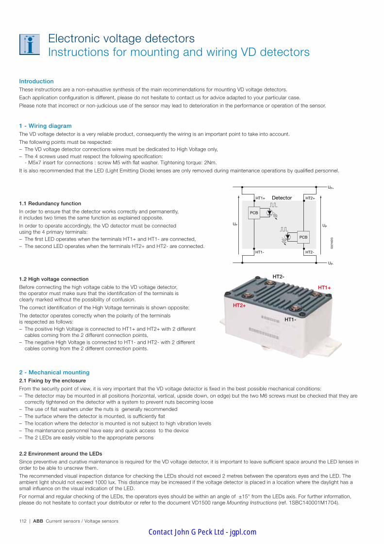
112 | ABB Current sensors / Voltage sensors
IntroductionThese instructions are a non-exhaustive synthesis of the main recommendations for mounting VD voltage detectors.
Each application configuration is different, please do not hesitate to contact us for advice adapted to your particular case.
Please note that incorrect or non-judicious use of the sensor may lead to deterioration in the performance or operation of the sensor.
1 - Wiring diagramThe VD voltage detector is a very reliable product, consequently the wiring is an important point to take into account.
The following points must be respected: – The VD voltage detector connections wires must be dedicated to High Voltage only, – The 4 screws used must respect the following specification:
- M5x7 insert for connections : screw M5 with flat washer. Tightening torque: 2Nm.
It is also recommended that the LED (Light Emitting Diode) lenses are only removed during maintenance operations by qualified personnel.
1.1 Redundancy function
In order to ensure that the detector works correctly and permanently, it includes two times the same function as explained opposite.
In order to operate accordingly, the VD detector must be connected using the 4 primary terminals: – The first LED operates when the terminals HT1+ and HT1- are connected, – The second LED operates when the terminals HT2+ and HT2- are connected.
1.2 High voltage connection
Before connecting the high voltage cable to the VD voltage detector, the operator must make sure that the identification of the terminals is clearly marked without the possibility of confusion.
The correct identification of the High Voltage terminals is shown opposite:
The detector operates correctly when the polarity of the terminals is respected as follows: – The positive High Voltage is connected to HT1+ and HT2+ with 2 different cables coming from the 2 different connection points,
– The negative High Voltage is connected to HT1- and HT2- with 2 different cables coming from the 2 different connection points.
2 - Mechanical mounting2.1 Fixing by the enclosure
From the security point of view, it is very important that the VD voltage detector is fixed in the best possible mechanical conditions: – The detector may be mounted in all positions (horizontal, vertical, upside down, on edge) but the two M6 screws must be checked that they are correctly tightened on the detector with a system to prevent nuts becoming loose
– The use of flat washers under the nuts is generally recommended – The surface where the detector is mounted, is sufficiently flat – The location where the detector is mounted is not subject to high vibration levels – The maintenance personnel have easy and quick access to the device – The 2 LEDs are easily visible to the appropriate persons
2.2 Environment around the LEDs
Since preventive and curative maintenance is required for the VD voltage detector, it is important to leave sufficient space around the LED lenses in order to be able to unscrew them.
The recommended visual inspection distance for checking the LEDs should not exceed 2 metres between the operators eyes and the LED. The ambient light should not exceed 1000 lux. This distance may be increased if the voltage detector is placed in a location where the daylight has a small influence on the visual indication of the LED.
For normal and regular checking of the LEDs, the operators eyes should be within an angle of ±15° from the LEDs axis. For further information, please do not hesitate to contact your distributor or refer to the document VD1500 range Mounting Instructions (ref. 1SBC140001M1704).
Electronic voltage detectors Instructions for mounting and wiring VD detectors
VD - Détecteur de Tension - page 10
G02
16D
G
UP
HT1+
HT1-
UP
HT2+
HT2-
Detector
PCB
UP+
UP-
PCB
HT2-
HT1-
HT1+
HT2+
Contact John G Peck Ltd - jgpl.com

ABB Current sensors / Voltage sensors | 113
Co
mm
on
info
rmat
ion
Electronic voltage detectors Instructions for mounting and wiring VD detectors
3 - 1st switching on of the detectorAfter applying high voltage to the primary terminals of the VD voltage detector, pay attention to the following points: – do not touch the HT terminals (high voltage) of the VD voltage detector – do not try to remove the lenses of the LEDs
3.1 Checking correct functioning
The VD voltage detector LEDs should flash about every 0.5 seconds as soon as the dangerous voltage UON is passed. The LEDs should remain extin-guished below UOFF, (see the detailed characteristics of the VD1500 voltage detector). In the event that LEDs do not work when high voltage is applied: – electrically isolate the system – make sure that no residual voltage is present in the VD voltage detector (voltmeter or other means) – check that the VD voltage detector wiring is correct (this may explain why the LEDs do not work)
If no faults are found in the installation, carry out a complete replacement of the voltage detector.
Please contact your distributor for further information on this subject or refer to the document Voltage Detector usage - Preventive and Curative Maintenance VD1500 Range (ref. 1SBD370058P0004).
4 - Preventive and curative maintenance of the detector4.1 Preventive maintenance – Checking the correct operation of the LEDs
Please refer to the checklist in the annexe of the document Voltage Detector usage - Preventive and Curative Maintenance VD1500 Range (ref. 1SBD370058P0004) for the weekly preventive maintenance operations to be carried out in order to guarantee the correct operation of the VD voltage detector.
– Replacement of the LEDs The VD voltage detector requires replacement of the LEDs, which increases the life of the sensor.
This replacement also implies basic checks in order to assure, from the security point of view, that VD voltage detector operates in good conditions.
LED replacement kit: kit including 5 LEDs mounted on plastic supports (ABB order code: 1SBT900000R2004). - Periodicity of preventive actions The maintenance operation must respect the main recommendations as follows: Operator: maintenance personnel Frequency: every 3 years Checklist: annexe of the document Voltage Detector usage - Preventive and Curative Maintenance VD1500 Range (ref. 1SBD370058P0004) Main actions: change the 2 LEDs.
- Updating of documentation The documentation associated with preventive maintenance must be up to date at every inspection operation.
4.2 Curative maintenance
During regular LEDs inspection or preventive maintenance visits, detector faults may be recorded. In such cases, the replacement of the defective part is imperative. – Definition of the kits 2 repair kits are available for VD voltage detectors:
LEDs replacement kit: ABB order code: 1SBT900000R2002 including 5 LEDs mounted on plastic supports
Lenses replacement kit: ABB order code 1SBT900000R2001 including 10 transparent plastic lenses.
– Replacement of parts and checking The maintenance operation must respect the main recommendations as follows: - Curative maintenance : Operator: maintenance personnel Frequency: immediately after the detection of the fault Checklist: annexe of the document Voltage Detector usage - Preventive and Curative Maintenance VD1500 Range (ref. 1SBD370058P0004) Main actions: change the 2 LEDs or the 2 lenses or the detector.
- Updating of documentation The documentation associated with preventive maintenance must be up to date at every inspection operation.
In all cases, the maintenance operation must be carried out with maximum precaution for the safety of personnel and the system where the detector is mounted must be checked that there is no voltage present. – Complete replacement of a detector In the case of complete replacement of a detector, follow the instructions in the documentation VD1500 range Mounting Instructions (ref. 1SBC140001M1704). - Updating of documentation The documentation associated with preventive maintenance must be up to date at every inspection operation.
LED on plastic support
Contact John G Peck Ltd - jgpl.com

114 | ABB Current sensors / Voltage sensors
QuestionnaireCurrent and voltage sensor selection guide
GeneralThe following questionnaires are used to select sensors according to the client's requirements.
The characteristics shown in the catalogue are given with respect to a defined environment (worst case conditions).
The technical requirements will not always reach these extreme limits, and it is possible, following confirmation by us, to propose higher maximum electrical or thermal values to those published, thanks to a knowledge and detailed analysis of the sensor operating environment.
A technical relationship between the client and ABB will allow the proposal of the best selection of sensors, equally from the viewpoint of perfor-mance and economy.
Two principal areas are considered in the selection of a sensor: – the electrical aspect – the thermal aspect
The sensor performance is based on a combination of electrical and thermal conditions; any values other than those indicated in this catalogue cannot be guaranteed unless validated by us.
The information below is only valid for sensors using closed loop Hall effect technology.
Contact your local supplier for other technologies.
Profile missionDue to the design of converters with integrate more power with less volume, sensors are very constraint; leading to reduce their life time. As a matter of fact, even though the application main conditions are well within the sensors characteristics, these conditions have an impact on the sensor life time.
The main general characteristics that involves the sensors life time are the following: – the ambient temperature above 40°C. It is usually said that every additional 10°C, the life time is reduced by a factor of 2. Of course, this value is a theoretical value and has to be defined in line with the concerned project.
– the ambient temperature variations also impact the sensor life time. Even small variations (like 10°C) can change the life time of the sensor espe-cially on the electronic part.
– the way the sensors are used also impact its duration (numbers of ON/OFF per day, average current or voltage value, power supply value, load resistor value, vibrations levels…)
The above general impacting conditions are well defined in standards like IEC 62380, UTE C 80-810 and must be consider during any new con-verter design.
ABB can provide theoretical reliability calculation based on specific profile mission of your projects.
Electrical characteristicsThe electrical characteristics values mentioned in this catalogue are given for a particular sensor operating point. These values may vary, according to the specific technical requirement, in the following way: – The primary thermal current (voltage) (IPN or UPN) may be increased if:
- the maximum operating temperature is lower than the value shown in the technical data sheet
- the sensor supply voltage (VA) is reduced - the load resistance value (RM) is increased
– The maximum current (voltage) measurable by the sensor may be increased if: - the maximum operating temperature is lower than the value shown in the technical data sheet
- the sensor supply voltage (VA) is increased - the secondary winding resistance value (RS) is reduced (e.g. by using a lower transformation ratio)
- the load resistance value (RM) is reduced
Thermal characteristicsThe operating temperature values mentioned in this catalogue are given for a particular sensor operating point. These values may vary, accord-ing to the specific technical requirement, in the following way: – The maximum operating temperature may be increased if:
- the primary thermal current (voltage) (IPN or UPN) is reduced - the sensor supply voltage (VA) is reduced - the load resistance value (RM) is increased
PS: The minimum operating temperature cannot be lower than that shown in the technical data sheet as this is fixed by the lower temperature limit of the components used in the sensor.
Contact John G Peck Ltd - jgpl.com

ABB Current sensors / Voltage sensors | 115
Co
mm
on
info
rmat
ion
Application1. Application :
– Variable speed drive ................................................................
– UPS .......................................................................................
– Wind generator .......................................................................
– Active harmonic filter ...............................................................
– Welding machines ...................................................................
– Solar ...................................................................................... – Other (description) ......................................................................
2. Quantity per year: ...........................................................................
Mechanical characteristics1. Sensor fixing:
– By soldering to the PCB ..........................................................
– By the enclosure .....................................................................
– By the primary conductor ........................................................
2. Primary conductor: – Cable diameter ................................................................... (mm) – Cable connection size ......................................................... (mm) – Bar size .............................................................................. (mm)
3. Secondary connection:
– By connector ..........................................................................
– By cable without connector .....................................................
– Other ......................................................................................
Sensor environmental conditions1. Minimum operating temperature ................................................ (°C)
2. Maximum operating temperature ............................................... (°C)
3. Presence of strong electromagnetic fields ....................................
4. Max. continuous primary conductor voltage ................................ (V)
5. Main reference standards ................................................................
QuestionnaireIndustry current sensor selection
Electrical characteristics1. Nominal current (IPN) ......................................................... (A r.m.s.)
2. Current type (if possible, show current profile on graph):
– Direct .....................................................................................
– Alternating ..............................................................................
3. Bandwidth to be measured ...................................................... (Hz)
4. Current measuring range: – Minimum current .................................................................... (A) – Maximum current ................................................................... (A) – Duration (of max. current) .................................................... (sec) – Repetition (of max. current) ........................................................ . – Measuring voltage (on RM) at max current .............................. (V)
5. Overload current (not measurable): – Not measurable overload current .......................................... (A) – Duration.............................................................................. (sec) – Repetition ...................................................................................
6. Sensor supply voltage: – Bipolar supply voltage .......................................................... (±V) – Unipolar supply voltage .......................................... (0 +V or 0 -V)
7. Output current – Secondary current at nominal current IPN ............................. (mA)
8. Current output (NCS range only) – Secondary current at maximum current IPMAX ....................... (mA)
9. Voltage output – Secondary voltage at nominal current IPN ............................... (V)
10. Voltage output (NCS range only) – Secondary voltage at maximum current IPMAX ......................... (V)
Company:
Address:
Tel:
Name:
Fax: Email:
Other requirements (description)
This document is used for selecting sensors according to the application and the clients requirements.
Contact John G Peck Ltd - jgpl.com
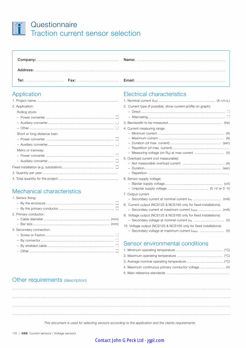
116 | ABB Current sensors / Voltage sensors
QuestionnaireTraction current sensor selection
Company:
Address:
Tel:
Name:
Fax: Email:
Other requirements (description)
This document is used for selecting sensors according to the application and the clients requirements.
Application1. Project name ...................................................................................
2. Application:
Rolling stock:
– Power converter .....................................................................
– Auxiliary converter ...................................................................
– Other ......................................................................................
Short or long distance train:
– Power converter .....................................................................
– Auxiliary converter ...................................................................
Metro or tramway:
– Power converter .....................................................................
– Auxiliary converter ...................................................................
Fixed installation (e.g. substation).....................................................
3. Quantity per year: ............................................................................
4. Total quantity for the project.............................................................
Mechanical characteristics1. Sensor fixing:
– By the enclosure .....................................................................
– By the primary conductor ........................................................
2. Primary conductor: – Cable diameter ................................................................... (mm) – Bar size .............................................................................. (mm)
3. Secondary connection:
– Screw or Faston......................................................................
– By connector ..........................................................................
– By shielded cable ....................................................................
– Other ......................................................................................
Electrical characteristics1. Nominal current (IPN) .......................................................... (A r.m.s.)
2. Current type (if possible, show current profile on graph):
– Direct .....................................................................................
– Alternating ..............................................................................
3. Bandwidth to be measured ....................................................... (Hz)
4. Current measuring range: – Minimum current .................................................................... (A) – Maximum current ................................................................... (A) – Duration (of max. current) .................................................... (sec) – Repetition (of max. current) ......................................................... – Measuring voltage (on RM) at max current .............................. (V)
5. Overload current (not measurable): – Not measurable overload current ........................................... (A) – Duration.............................................................................. (sec) – Repetition ...................................................................................
6. Sensor supply voltage: – Bipolar supply voltage .......................................................... (±V) – Unipolar supply voltage .......................................... (0 +V or 0 -V)
7. Output current – Secondary current at nominal current IPN ............................. (mA)
8. Current output (NCS125 & NCS165 only for fixed installations) – Secondary current at maximum current IPMAX ....................... (mA)
9. Voltage output (NCS125 & NCS165 only for fixed installations) – Secondary voltage at nominal current IPN ............................... (V)
10. Voltage output (NCS125 & NCS165 only for fixed installations) – Secondary voltage at maximum current IPMAX ......................... (V)
Sensor environmental conditions1. Minimum operating temperature ................................................ (°C)
2. Maximum operating temperature ............................................... (°C)
3. Average nominal operating temperature ......................................(°C)
4. Maximum continuous primary conductor voltage .......................... (V)
5. Main reference standards ................................................................
Contact John G Peck Ltd - jgpl.com

ABB Current sensors / Voltage sensors | 117
Co
mm
on
info
rmat
ion
QuestionnaireTraction voltage sensor selection
Company:
Address:
Tel:
Name:
Fax: Email:
Other requirements (description)
This document is used for selecting sensors according to the application and the clients requirements.
Application1. Project name ...................................................................................
2. Application:
Short or long distance train:
– Power converter .....................................................................
– Auxiliary converter ...................................................................
Metro or tramway:
– Power converter .....................................................................
– Auxiliary converter ...................................................................
Fixed installation (e.g. substation) ................................................
3. Quantity per year: ............................................................................
4. Total quantity for the project.............................................................
Mechanical characteristics1. Primary connection:
– By screw ................................................................................
– Other ......................................................................................
2. Secondary connection:
– Screw or Faston......................................................................
– By connector ..........................................................................
– Other ......................................................................................
Electrical characteristics1. Nominal voltage (UPN) ........................................................ (V r.m.s.)
2. Voltage type (if possible, show voltage profile on graph):
– Direct .....................................................................................
– Alternating ..............................................................................
3. Bandwidth to be measured ...................................................... (Hz)
4. Voltage measuring range: – Minimum voltage .................................................................... (V) – Maximum voltage ................................................................... (V) – Duration (at max. voltage) .................................................... (sec) – Repetition (at max. voltage) ......................................................... – Measuring voltage (on RM) at max voltage ............................... (V)
5. Overload voltage (not measurable): – Not measurable overload voltage ............................................ (V) – Duration.............................................................................. (sec) – Repetition ................................................................................... – Category (from OV1 to OV3) ........................................................
6. Sensor supply voltage: – Bipolar supply voltage .......................................................... (±V) – Unipolar supply voltage .......................................... (0 +V or 0 -V)
7. Output current – Secondary current at nominal voltage UPN ............................ (mA)
Sensor environmental conditions1. Minimum operating temperature ................................................ (°C)
2. Maximum operating temperature ............................................... (°C)
3. Average nominal operating temperature .....................................(°C)
4. Main reference standards ................................................................
Contact John G Peck Ltd - jgpl.com

118 | ABB Current sensors / Voltage sensors
QuestionnaireVoltage detector selection
Company:
Address:
Tel:
Name:
Fax: Email:
Other requirements (description)
This document is used for selecting sensors according to the application and the clients requirements.
Application1. Project name ...................................................................................
2. Application:
Short or long distance train:
– Power converter .....................................................................
– Auxiliary converter ...................................................................
Metro or tramway:
– Power converter .....................................................................
– Auxiliary converter ...................................................................
Fixed equipment (e.g. substation) ................................................
3. Quantity per year: ...........................................................................
4. Total quantity for the project.............................................................
Electrical characteristics1. Nominal voltage (UPN) ............................................................ (V DC)
2. Maximum voltage long duration: 5min (UMAX2) ......................... (V DC)
3. Maximum voltage overload: 20ms (UMAX3) ............................... (V DC)
4. Minimum voltage to be detected ................................................. (V)
Sensor environmental conditions1. Minimum operating temperature ................................................ (°C)
2. Maximum operating temperature ............................................... (°C)
3. Average nominal operating temperature ..................................... (°C)
4. Pollution degree ..............................................................................
5. Over voltage category (from OV1 to OV3) ........................................
6. Maximum ambient light level ...................................................... (lux)
7. Main reference standards ................................................................
Contact John G Peck Ltd - jgpl.com

ABB Current sensors / Voltage sensors | 119
Co
mm
on
info
rmat
ion
Notes
Contact John G Peck Ltd - jgpl.com
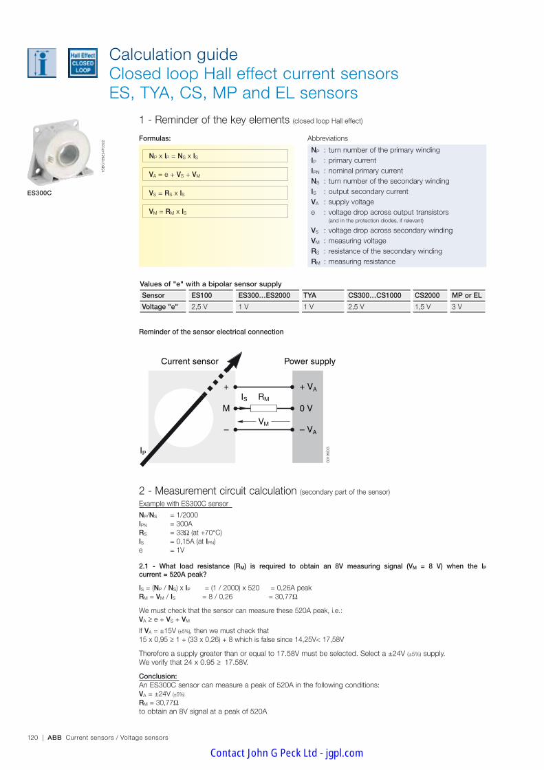
120 | ABB Current sensors / Voltage sensors
Calculation guideClosed loop Hall effect current sensorsES, TYA, CS, MP and EL sensors
1 - Reminder of the key elements (closed loop Hall effect)
Formulas: Abbreviations
M
+IS
IP
–
0 V
+ VA
– VA
G01
96D
G
Current sensor Power supply
RM
VM
ES300C
2 - Measurement circuit calculation (secondary part of the sensor)
Example with ES300C sensor
Np/Ns = 1/2000IpN = 300ARs = 33Ω (at +70°C)Is = 0,15A (at IpN)e = 1V
2.1 - What load resistance (RM) is required to obtain an 8V measuring signal (VM = 8 V) when the IP current = 520A peak?
Is = (Np / Ns) x Ip = (1 / 2000) x 520 = 0,26A peakRm = Vm / Is = 8 / 0,26 = 30,77Ω
We must check that the sensor can measure these 520A peak, i.e.:VA > e + Vs + Vm
If VA = ±15V (±5%), then we must check that15 x 0,95 > 1 + (33 x 0,26) + 8 which is false since 14,25V< 17,58V
Therefore a supply greater than or equal to 17.58V must be selected. Select a ±24V (±5%) supply.We verify that 24 x 0.95 > 17.58V.
Conclusion:An ES300C sensor can measure a peak of 520A in the following conditions:VA = ±24V (±5%)
Rm = 30,77Ωto obtain an 8V signal at a peak of 520A
Np x Ip = NS x Is
VA = e + Vs + Vm
Vs = Rs x Is
Vm = Rm x Is
Values of "e" with a bipolar sensor supply
Sensor ES100 ES300…ES2000 TYA CS300…CS1000 CS2000 MP or EL
Voltage "e" 2,5 V 1 V 1 V 2,5 V 1,5 V 3 V
Reminder of the sensor electrical connection
Np : turn number of the primary windingIp : primary currentIpN : nominal primary currentNs : turn number of the secondary windingIs : output secondary currentVA : supply voltagee : voltage drop across output transistors (and in the protection diodes, if relevant)
Vs : voltage drop across secondary windingVm : measuring voltageRs : resistance of the secondary windingRm : measuring resistance
G01
96D
G
1SB
C78
9824
F030
2
Contact John G Peck Ltd - jgpl.com

ABB Current sensors / Voltage sensors | 121
Co
mm
on
info
rmat
ion
Calculation guideClosed loop Hall effect current sensorsES, TYA, CS, MP and EL sensors
ES300C
2.2 - What are the consequences, if the required signal is only 5V?
Rm = Vm / IS = 5 / 0,26 = 19,23Ω
We must check that the sensor can measure these 520A peak.VA > e + VS + Vm
If VA = ±15V (±5%), then we must check that15 x 0.95 > 1 + (33 x 0.26) + 5 which is false since 14.25V< 14.58V
Therefore a supply greater than or equal to 14.58V must be selected. Select a ±24V (±5%) supply or a ±15V supply with a tighter tolerance, for example ±15V (±2%).(since 15V x 0.98 > 14.58V)
Conclusion :An ES300C sensor can measure a peak of 520A in the following conditions:VA = ±15V (±2%)
Rm = 19,23Ωto obtain a 5V signal at a peak of 520A.In general, the larger the measuring signal required, the larger the load resistance and the higher the sensor supply voltage should be. The thermal aspect of the sensor should be considered.
2.3 - What is the maximum current measurable by an ES300C in specific conditions?For example, the conditions are:VA = ±15V (±5%)
Rm = 15Ω
From the base formulas, we obtain the following formula:ISMAX = (VAMIN - e) / (Rs + Rm) = [(15 x 0,95) – 1] / (33 + 15) = 0,276A peak
Now calculate the equivalent primary current:Ip = (Ns / Np) x Is = (2000 / 1) x 0,276 = 552A peak
Conclusion :An ES300C sensor can measure a peak of 552A in the following conditions:VA = ±15V (±5%)
Rm = 15ΩNote: the 552A peak current must not be a continuous current. For specific requirements, contact your dis-tributor.
2.4 - What influence does the ambient temperature have on the sensor's performance?Taking the conditions from point 2.3 (preceding example). The calculations were made using a maxi-mum default operating temperature of +70°C. If this maximum temperature is +50°C, then the measuring range can be increased as follows:
Rs = 33Ω at +70°C At +50°C, Rs = 30,5Ω then,ISMAX = (VAMIN - e) / (Rs + Rm) = [(15 x 0,95) – 1] / (30,5 + 15) = 0,291A peak
Now calculate the equivalent primary current:Ip = (Ns / Np) x Is = (2000 / 1) x 0,291 = 582A peak
Conclusion :An ES300C sensor can measure a peak of 582A in the following conditions:VA = ±15V (±5%)
Rm = 15ΩMax. operating temperature = +50°CNote: the 582A peak current must not be a continuous current. For specific requirements, contact your distributor. In general, the lower the ambient temperature, the more important the sensor measurable current. The thermal aspect of the sensor should be considered.
1SB
C78
9824
F030
2
Contact John G Peck Ltd - jgpl.com

122 | ABB Current sensors / Voltage sensors
Calculation guideClosed loop Hall effect current sensorsES, TYA, CS, MP and EL sensors
ES300C
2.5 - What influence does the turn ratio have on the sensor's performance?Taking the conditions of point 2.3 again. The calculations were based on a turn ratio of 1/2000. If this ratio is 1/1500 (non standard ratio for a 300A sensor), then the elements are determined as follows:
Is = (Np / Ns) x Ip = (1 / 1500) x 552 = 0,368 peak (Ip = 522A from 2.3 above)
Now calculate the voltage obtained at the terminals of the measuring resistance:
for a turn ratio of 1/2000: Vm = Rm x Is = 15 x 0,276 = 4,14V
for a turn ratio of 1/1500: Vm = Rm x Is = 15 x 0,368 = 5,52V
Conclusion :An ES300C sensor can measure a peak of 552A in the following conditionsVA = ±15V (±5%)
Rm = 15ΩVm = 4.14V with a turn ratio of 1/2000Vm = 5.52V with a turn ratio of 1/1500In general, the lower the turn ratio, the more important the output current and the higher the measuring volt-age. The thermal aspect of the sensor should be considered.
2.6 - What influence does the supply voltage have on the sensor's performance? Taking the conditions in point 2.3 again. The calculations were based on a supply voltage of ±15V (±5%).Reworking the calculations with a supply of ±24V (±5%).
From the base formulas, we obtain the following formula:ISMAX = (VAMIN - e) / (Rs + Rm) = [(24 x 0,95) – 1] / (33 + 15) = 0,454A peak
Now calculate the equivalent primary current:Ip = (Ns / Np) x Is = (2000 / 1) x 0,454 = 908A peak
Conclusion :An ES300C sensor can measure a peak of 908A in the following conditions:VA = ±24V (±5%)
Rm = 15ΩNote: the 908A peak current must not be a continuous current. In general, the higher the supply voltage, the more important the measuring current and the higher the meas-uring voltage. The thermal aspect of the sensor should be considered.
NB: for calculations with unipolar supply (e.g. 0…+24V), contact your distributor.
1SB
C78
9824
F030
2
Contact John G Peck Ltd - jgpl.com

ABB Current sensors / Voltage sensors | 123
Co
mm
on
info
rmat
ion
Calculation guideElectronic technology current sensors NCS sensors
NCS - Instruction de montage et câblage Capteurs P94 à 96/120Schéma de câblage NCS_1
Power supplyNCS sensor
G02
20D
GVs2
0V
Is2
Vs1
- VA
Is1
+ VA
0V
IpRM3
RM2
RM1Is1
Is2
- VA
+ VA
0V
VM2
VM1
VM3
RM4
VM4
NCS125-10
1 - Reminder of the key elements
Formulas: Abbreviations
2 - Measurement circuit calculation (current output)
Example with NCS125-4 sensor
IPN = 4 000A Is1 @ IpN = ±20mAIpmAX = 20 000A Is2 @ IpMAX = ±20mARm = 0 - 350Ω (IS1 & IS2) Vs1 @ IpN = ±10VRm > 10kΩ (VS2 & VS2) Vs2 @ IPMAX = ±10VVA = ±15V ... ±24V
The supply voltage does not have any influence on the output signals.
2.1 - What load resistance (RM) is required to obtain a 5V measuring (VM = 5V) when the current IP = 6000A peak?The measured current is greater than IpN (4000A for a NCS125-4), IS2 is therefore used as the measuring signal. Firstly the output current on IS2 must be calculated when IpN = 6000 A DCIS2 = IPN / IPMAX x ISMAX = 6000 / 20000 x 20 = 6 mA (correct because IS2MAX = ±20 mA DC)Now determine the value of the resistance RM
RM = VM / IS2 = 5 / 0.006 = 833.33 Ω
Conclusion:The NCS125-4 sensor can measure 6000A peak on the signal output IS2 with a resistance of 416.67 Ω (greater than 350 Ω) because the output current is smaller than IsmAX i.e. 20mA DCThe product of Rm x IsmAX must always be smaller than or equal to maximum output of 7V DC
3 - Measurement circuit calculation (voltage output)
No special calculation needs to be made. This NCS sensor range supplies a voltage directly proportional to the primary current Ip between -10V and +10V. A load resistance of a value greater than or equal to 10kΩ adapts the impedance of the measured output (VS1 or VS2) to the acquisition system.
VM1 = RM1 x IS1
VM2 = RM2 x IS2
with 0Ω < RM1 or RM2 < 350Ω
Reminder of the sensor electrical connection
IP : primary currentIPN : nominal primary currentIPMAX : maximum primary currentIS1 : secondary current at IPN
IS2 : secondary current at IPMAX
VS1 : secondary voltage at IPN
VS2 : secondary voltage at IPMAX
VA : supply voltageVM : measuring voltageRM : measuring resistanceRMMIN : minimum measuring resistance RMMAX : maximal measuring resistance
The design of the sensor requires that 2 operating points are respected on the outputs IS1 and IS2:• A maximum measuring voltage of 7V DC (VMMAX ≤ RMMAX x ISMAX)• A maximum output current of ±20mA DC.
1SB
C14
6016
F001
4
Contact John G Peck Ltd - jgpl.com

124 | ABB Current sensors / Voltage sensors
Calculation guideElectronic technology voltage sensors VS sensors
VS1000B
UP : primary voltageUPN : nominal primary voltage IS : secondary currentISN : nominal secondary currentVA : supply voltageVAMIN : VA less lowest supply toleranceVM : measuring voltageRM : measuring resistance
1 - Reminder of the key elementsFormulas: Abbreviations
Vm = Rm x Is and UpN
= Up
IsN Is
Rm = [(0,8 x VAmIN) / Is] – 55 UHT+ + UHT- < 4.2 kV peak and
I UHT+ - UHT- I < UpmAX
VS50 ... VS1500:
Rm = [(0,8 x VAmIN) / Is] – 60 UHT+ + UHT- < 10 kV peak and
I UHT+ - UHT- I < UpmAX
VS2000 ... VS4200 :
Reminder of the sensor electrical connection
M
+
UP
HT +
HT –
IS
–
0 V
+ VA
– VA
G01
93D
G
VS sensor Power supply
RM
VM
2 - Measurement circuit calculation (secondary part of the sensor)
Example with VS1000B sensorUpN = 1000VIsN = 50mAVA = ±24V (±5%)
UpmAX = 1500V
2.1 - What load resistance (RM) is required to obtain a 10V measuring signal (VM = 10V) when the voltage UPMAX = 1500V peak?Is = IsN x UpmAX / UpN = 0,050 x 1500 / 1000 i.e. Is = 75mARm = Vm / Is = 10 / 0,075 i.e. Rm = 133,33Ω
We must check that the sensor can measure this 1500V with a ±24V (±5%) supplyVAmIN = 24 x 0,95 = 22,8VRm = [(0,8 x VAmIN) / Is] – 55 = [(0,8 x 22,8) / 0,075] – 55 i.e. Rm = 188,2Ω
We therefore verify that the sensor can measure this 1500V voltage since the measuring resistance with a ±24V (±5%) supply is 188.2Ω for 133.33Ω required.
Conclusion :A VS1000B sensor can measure a peak of 1500V in the following conditions:VA = ±24V (±5%)
Rm = 133,33Ωto obtain a 10V signal at 1500V peak.
G01
93D
G
1SB
C78
9884
F030
2
Contact John G Peck Ltd - jgpl.com

ABB Current sensors / Voltage sensors | 125
Co
mm
on
info
rmat
ion
VS1000B
Calculation guideElectronic technology voltage sensors VS sensors
2.2 - What are the consequences, if the required signal is only 5V (VM = 5V)? In the same way as for closed loop Hall effect current sensors (see page 120), if the required measuring voltage is reduced, carefully check that the ±15V (±5%) supply used in this example is sufficient to obtain a 5V signal with the conditions used in the preceding point.
Rm = Vm / Is = 5 / 0,075 i.e. Rm = 66,67ΩRm = [(0,8 x VAmIN) / Is] – 55 = [(0,8 x 14,25) / 0,075] – 55 i.e. Rm = 97Ω
We therefore verify that the sensor measures this 1500V voltage since the measuring resistance with a ±15V (±5%) supply is 97Ω for 66.67Ω required.
2.3 - What is the maximum measurable voltage by a VS1000B in specific conditions?An electronic voltage sensor is also sensitive to the thermal aspect.In general, a VS voltage sensor can withstand up to 150% of the nominal primary voltage, but only under certain conditions.In all these cases, we recommend that you contact your distributor in order to obtain detailed information on this subject.
2.4 - What influence does the ambient temperature have on the sensor's performance?The electronic voltage sensor design means that the maximum operating temperature influences the sensor's performance, notably the measurement accuracy. However there is no correlation between a reduction in the ambient temperature and an increase in the voltage to be measured.
2.5 - What influence does the supply voltage have on the sensor performance?In general, the higher the supply voltage, the higher the measuring voltage. The thermal aspect of the sensor should be considered.
NB: for calculations with unipolar supply (e.g. 0…+24V), contact your distributor.
2.6 - What influence does the temperature have on the sensor's life time?From a general point of view, with whatever product, the more the temperature, the less the life time. With the VS sen-sors, the temperature also reduces the life time above 40°C. The factor of reduction is however very much depending on the way the VS sensors are used in the application. Please contact your local supplier for further information.
3 - Sensor primary circuit calculationMaximum common mode voltage:
Can the VS1000B sensor (UPMAX = 1500V peak) be used to measure a differential voltage
Up = UHT+ - UHT- with UHT+ = 3500V DC and UHT- = 2600V DC ?
3.1 - I UHT+ - UHT- I = I 3500 - 2600 I = 900V DC < 1500V peak :
First condition I UHT+ - UHT- I < UpmAX is therefore fulfilled.
3.2 - UHT+ + UHT- = 3500 + 2600 = 6100V DC > 4.2kV peak :
Second condition UHT+ + UHT- < 4.2kV peak is not therefore fulfilled.
Conclusion :The VS1000B sensor cannot therefore be used to measure this 900V DC primary differential voltage (even though this differential voltage is lower than the nominal primary voltage of the VS1000B sensor).
For this application the VS2000B sensor can be used since:
UHT+ + UHT- = 6100V DC < 10kV peak
The condition UHT+ + UHT- < 10kV peak is therefore fulfilled with the VS2000B.
1SB
C78
9884
F030
2
Contact John G Peck Ltd - jgpl.com

126 | ABB Current sensors / Voltage sensors
Europe
Our distributors
GermanyGvA Leistungselektronik GmbHBoehringer Strasse 10-12MannheimD-68307Tel: +49 (0) 621 / 78 99 2-0Fax: +49(0) 621 / 78 99 2-99E-mail: [email protected]
www.gva-leistungselektronik.de
FranceCompelec325, rue Maryse Bastié 69140 Rillieux la PapeTel: +33 (0)4 72 08 80 80Fax: +33 (0)4 72 08 82 15E-mail: [email protected]
SwitzerlandElektron AGRiedhofstrasse 11Au ZHCH-8804Tel: +41 (0) 1 781 02 34Fax: +41 (0) 1 781 06 07E-mail: [email protected]
www.elektron.ch
DenmarkDovitech A/S Midtager 29 2605 BrøndbyTel: +45 70 25 26 50Fax: +45 70 25 26 51E-mail: [email protected]
www.dovitech.dk/
Italy Staer S.r.l.Via Sibilla Alemaro, 420090 Segrate (Milano)Tel: +39 02 2695 2067Fax: +39 02 2692 2849E-mail: [email protected]
www.staermisure.it
Czech RepublicABB S.r.o. ELSYNNHerspicka, 13Brno 619 00Tel: +420 543 145 456Tel: +420 543 243 489E-mail: [email protected]
Benelux KWx B.VChristiaan Huygensstraat 5NL-3261 LR Oud-BeijerlandTel: +31 (0) 186-633602Fax: +31 (0) 186-633605E-mail: [email protected]
www.kwx.nl
TurkeyOHM ElektronikKemeralti Caddesi Ada HanN°87 Kat5 KaraköyIstanbul 80030 TophaneTel: +90 (0) 212 293 95 91Fax: +90 (0) 212 244 27 72E-mail: [email protected]
www.ohm.com.tr
SpainCatelecC/. L'enginys/n, Nave 7Viladecans E-08840Tel: +34 93 638 4622Fax: +34 93 638 4691E-mail: [email protected]
PolandPPH Comel Sp. z o.o. Oddzial Gdyniaul. Orlowska 49 C81-522 GdyniaTel: 058 6610167 Fax: 058 6248573E-mail: [email protected]
www.comel.pl
RussiaABB RussiaAP DivisionObrucheva 30/1, Bld 2117997 Moscow Russian FederationTel: +7 495 960 2200Fax: +7 495 960 2200
www.abb.com.ru
UKJohn G. Peck LimitedUnit B1, Wymeswold Industrial ParkWymeswold Lane,Burton on the WoldsLoughborough, Leicestershire LE12 5TYUnited KingdomsTel: +44 (0) 1509 88 1010Fax: +44 (0) 1509 88 1688E-mail: [email protected]
www.jgpl.com
Contact John G Peck Ltd - jgpl.com

ABB Current sensors / Voltage sensors | 127
Asia
America
You can contact us by e-mail: [email protected]
Other countries
Our distributors
China ABB (China) Ltd.Universal Plaza, 10 Jiuxiangiao LuChaoyang District,Beijing 100015 P.R China.Tel: +86 1084566688E-mail: [email protected]
www.abb.com.cn
IndiaABB LimitedPlot Nos 5 & 6 2nd Phase Peenya industrial AreaPB N°5806 Peenya560058 BangaloreTel: +91 8022948285
www.abb.com.in
TaïwanIndustrade Co., Ltd10F , N°29-1Zhong Zheng East RoadTamsui District, New Taipei City25170 Republic Of ChinaTel: +886 (2) 2809 1251Fax: +886 (2) 2808 4990E-mail: [email protected]
www.industrade.com.tw
JapanChronix Inc.Shinjuku-Monolith 13D,2-3-1 Nishishinjuku Shinjuku-ku Tokyo,163-0913JapanTel(Tokyo): (81)-3-5322-7191Fax(Tokyo): (81)-3-5322-7790E-mail: [email protected]
www.chronix.co.jp
KoreaMilim B214, Biz Center SK Technopark. 190-1,Sangdaewon-Dong, Jungwon-Gu, Seongnam-Si, Gyeonggi-Do 462-120, KOREA.Tel: + 82 31 776 2288~ 91 Fax: + 82 31 776 2292 E-mail: [email protected]
www.milimsys.com
United States 5 S Components, Inc.630 Fifth AvenueEast McKeesport, PA 15035Tel: +1 (412) 967 5858Fax: +1 (412) 967 5868E-mail: [email protected]
www.5scomponents.com
Contact John G Peck Ltd - jgpl.com
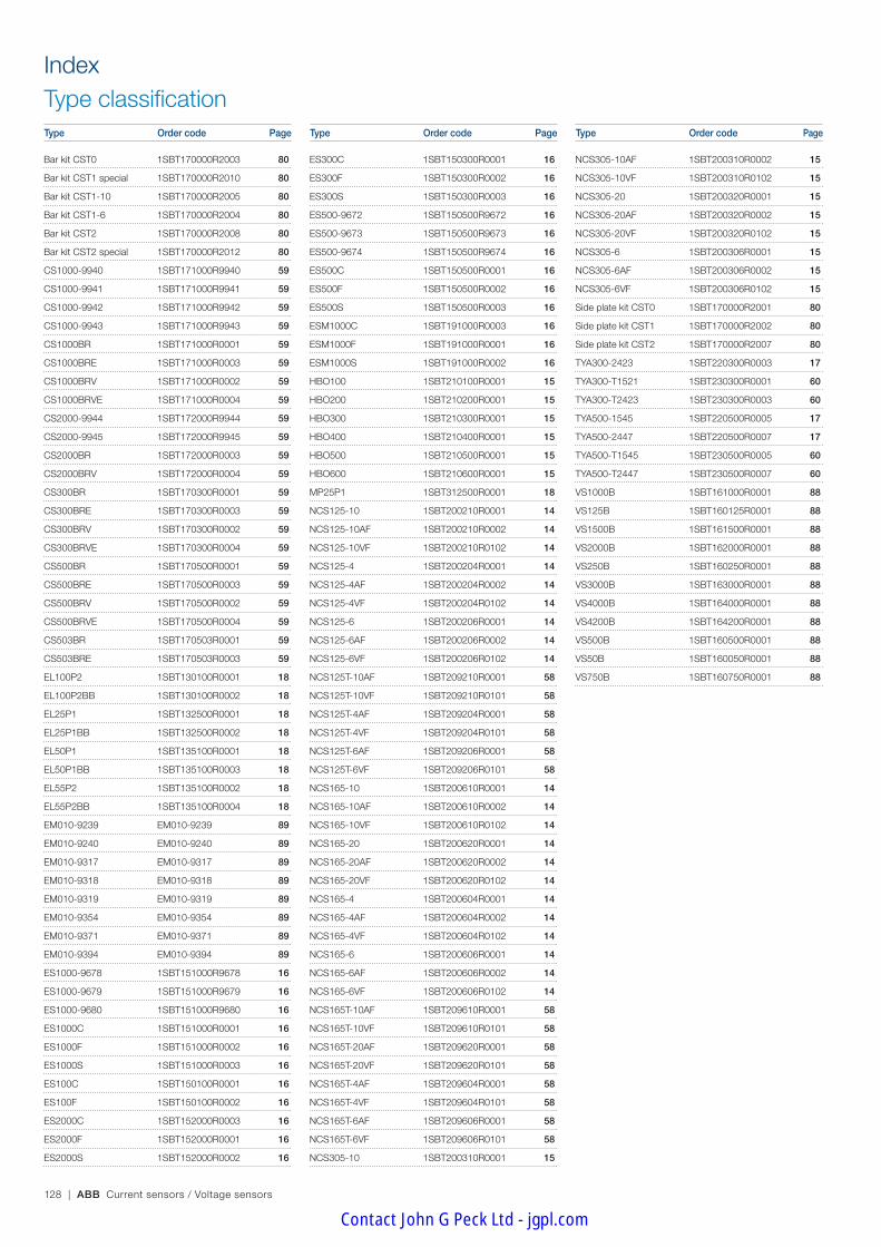
128 | ABB Current sensors / Voltage sensors
IndexType classificationType Order code Page Type Order code Page Type Order code Page
Bar kit CST0 1SBT170000R2003 80
Bar kit CST1 special 1SBT170000R2010 80
Bar kit CST1-10 1SBT170000R2005 80
Bar kit CST1-6 1SBT170000R2004 80
Bar kit CST2 1SBT170000R2008 80
Bar kit CST2 special 1SBT170000R2012 80
CS1000-9940 1SBT171000R9940 59
CS1000-9941 1SBT171000R9941 59
CS1000-9942 1SBT171000R9942 59
CS1000-9943 1SBT171000R9943 59
CS1000BR 1SBT171000R0001 59
CS1000BRE 1SBT171000R0003 59
CS1000BRV 1SBT171000R0002 59
CS1000BRVE 1SBT171000R0004 59
CS2000-9944 1SBT172000R9944 59
CS2000-9945 1SBT172000R9945 59
CS2000BR 1SBT172000R0003 59
CS2000BRV 1SBT172000R0004 59
CS300BR 1SBT170300R0001 59
CS300BRE 1SBT170300R0003 59
CS300BRV 1SBT170300R0002 59
CS300BRVE 1SBT170300R0004 59
CS500BR 1SBT170500R0001 59
CS500BRE 1SBT170500R0003 59
CS500BRV 1SBT170500R0002 59
CS500BRVE 1SBT170500R0004 59
CS503BR 1SBT170503R0001 59
CS503BRE 1SBT170503R0003 59
EL100P2 1SBT130100R0001 18
EL100P2BB 1SBT130100R0002 18
EL25P1 1SBT132500R0001 18
EL25P1BB 1SBT132500R0002 18
EL50P1 1SBT135100R0001 18
EL50P1BB 1SBT135100R0003 18
EL55P2 1SBT135100R0002 18
EL55P2BB 1SBT135100R0004 18
EM010-9239 EM010-9239 89
EM010-9240 EM010-9240 89
EM010-9317 EM010-9317 89
EM010-9318 EM010-9318 89
EM010-9319 EM010-9319 89
EM010-9354 EM010-9354 89
EM010-9371 EM010-9371 89
EM010-9394 EM010-9394 89
ES1000-9678 1SBT151000R9678 16
ES1000-9679 1SBT151000R9679 16
ES1000-9680 1SBT151000R9680 16
ES1000C 1SBT151000R0001 16
ES1000F 1SBT151000R0002 16
ES1000S 1SBT151000R0003 16
ES100C 1SBT150100R0001 16
ES100F 1SBT150100R0002 16
ES2000C 1SBT152000R0003 16
ES2000F 1SBT152000R0001 16
ES2000S 1SBT152000R0002 16
ES300C 1SBT150300R0001 16
ES300F 1SBT150300R0002 16
ES300S 1SBT150300R0003 16
ES500-9672 1SBT150500R9672 16
ES500-9673 1SBT150500R9673 16
ES500-9674 1SBT150500R9674 16
ES500C 1SBT150500R0001 16
ES500F 1SBT150500R0002 16
ES500S 1SBT150500R0003 16
ESM1000C 1SBT191000R0003 16
ESM1000F 1SBT191000R0001 16
ESM1000S 1SBT191000R0002 16
HBO100 1SBT210100R0001 15
HBO200 1SBT210200R0001 15
HBO300 1SBT210300R0001 15
HBO400 1SBT210400R0001 15
HBO500 1SBT210500R0001 15
HBO600 1SBT210600R0001 15
MP25P1 1SBT312500R0001 18
NCS125-10 1SBT200210R0001 14
NCS125-10AF 1SBT200210R0002 14
NCS125-10VF 1SBT200210R0102 14
NCS125-4 1SBT200204R0001 14
NCS125-4AF 1SBT200204R0002 14
NCS125-4VF 1SBT200204R0102 14
NCS125-6 1SBT200206R0001 14
NCS125-6AF 1SBT200206R0002 14
NCS125-6VF 1SBT200206R0102 14
NCS125T-10AF 1SBT209210R0001 58
NCS125T-10VF 1SBT209210R0101 58
NCS125T-4AF 1SBT209204R0001 58
NCS125T-4VF 1SBT209204R0101 58
NCS125T-6AF 1SBT209206R0001 58
NCS125T-6VF 1SBT209206R0101 58
NCS165-10 1SBT200610R0001 14
NCS165-10AF 1SBT200610R0002 14
NCS165-10VF 1SBT200610R0102 14
NCS165-20 1SBT200620R0001 14
NCS165-20AF 1SBT200620R0002 14
NCS165-20VF 1SBT200620R0102 14
NCS165-4 1SBT200604R0001 14
NCS165-4AF 1SBT200604R0002 14
NCS165-4VF 1SBT200604R0102 14
NCS165-6 1SBT200606R0001 14
NCS165-6AF 1SBT200606R0002 14
NCS165-6VF 1SBT200606R0102 14
NCS165T-10AF 1SBT209610R0001 58
NCS165T-10VF 1SBT209610R0101 58
NCS165T-20AF 1SBT209620R0001 58
NCS165T-20VF 1SBT209620R0101 58
NCS165T-4AF 1SBT209604R0001 58
NCS165T-4VF 1SBT209604R0101 58
NCS165T-6AF 1SBT209606R0001 58
NCS165T-6VF 1SBT209606R0101 58
NCS305-10 1SBT200310R0001 15
NCS305-10AF 1SBT200310R0002 15
NCS305-10VF 1SBT200310R0102 15
NCS305-20 1SBT200320R0001 15
NCS305-20AF 1SBT200320R0002 15
NCS305-20VF 1SBT200320R0102 15
NCS305-6 1SBT200306R0001 15
NCS305-6AF 1SBT200306R0002 15
NCS305-6VF 1SBT200306R0102 15
Side plate kit CST0 1SBT170000R2001 80
Side plate kit CST1 1SBT170000R2002 80
Side plate kit CST2 1SBT170000R2007 80
TYA300-2423 1SBT220300R0003 17
TYA300-T1521 1SBT230300R0001 60
TYA300-T2423 1SBT230300R0003 60
TYA500-1545 1SBT220500R0005 17
TYA500-2447 1SBT220500R0007 17
TYA500-T1545 1SBT230500R0005 60
TYA500-T2447 1SBT230500R0007 60
VS1000B 1SBT161000R0001 88
VS125B 1SBT160125R0001 88
VS1500B 1SBT161500R0001 88
VS2000B 1SBT162000R0001 88
VS250B 1SBT160250R0001 88
VS3000B 1SBT163000R0001 88
VS4000B 1SBT164000R0001 88
VS4200B 1SBT164200R0001 88
VS500B 1SBT160500R0001 88
VS50B 1SBT160050R0001 88
VS750B 1SBT160750R0001 88
Contact John G Peck Ltd - jgpl.com

Contact John G Peck Ltd - jgpl.com

ABB FranceLow Voltage Products Division Protection & Control Activity Current & Voltage Sensors Department3, rue Jean PerrinF-69687 Chassieu cedex / FranceTel. : +33 (0)4 7222 1722 Fax : +33 (0)4 7222 1984 E-Mail : [email protected]
1SB
C14
0152
C02
05 -
Prin
ted
in F
ranc
e (Q
t 04
.201
3 C
hira
t)NoteWe reserve the right to make technical changes or modify the contents of this document without prior notice. ABB does not accept any responsibility whatsoever for potential errors or possible lack of information in this document.
We reserve all rights in this document and in the subject matter and illustrations contained therein. Any reproduction, disclosure to third parties or utilization of its contents – in whole or in parts – is forbidden without prior written consent of ABB.
Copyright© 2013 ABB - All rights reserved
Contact us
www.abb.com
Contact John G Peck Ltd - jgpl.com