Embed Size (px)
Citation preview
21.11.20051
Technical Capabilities forFuel and Material Irradiation Testing at
the Halden ReactorT. Tverberg ([email protected]), W. Wiesenack, E. Kolstad, H. Thoresen, K. W. Eriksen, P. Bennett, T. M. Karlsen, N. W. Høgberg, R. Van Nieuwenhove
Institutt for energiteknikkOECD Halden Reactor Project
B. C. Oberländer, H-J Kleemann, H. K. Jenssen
Institutt for energiteknikkWorkshop on Modelling and Quality Control for Advanced and
Innovative Fuel TechnologiesTrieste, Italy, Nov 17 –18 2005
21.11.20052
Contents0. About the Halden Reactor Project and the Halden Reactor
1. Instruments and techniques for flux monitoring / control a. Gamma flux measurementsb. Neutron flux measurementsc. Flux shielding / flux depression
• He-3 coils• Moveable neutron shields

21.11.20053
Contents (contd.)2. Fuel rod instrumentation:
a. Thermocouples• Fuel temperature• Cladding temperature
b. The Linear Voltage Differential Transformer (LVDT)• Fuel stack elongation detector EF• Cladding extensometer EC • Fuel rod pressure transducer PF• Expansion thermometer ET (average fuel centre temperature)
c. Fuel rod gas flow/pressure lines • Radioactive fission gas release, gas flow and overpressure
d. Re-instrumentation techniques

21.11.20054
Contents (contd.)3. Materials testing
a. LWR loop systemsb. Crack growth measurements with potential drop techniquec. Crack initiationd. Clad diameter measurements
• Cladding creep• PWR CRUD
e. Stress relaxation
21.11.20055
Contents (contd.)
4. Instrumentation development for materials studiesa. In-core conductivity cellb. On-line potential drop corrosion monitorc. Controlled distance electrochemistry measurementsd. Electrochemical impedance spectroscopye. ECP reference electrodes
21.11.20056
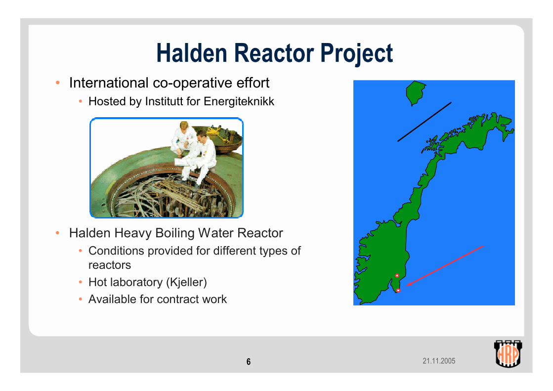
Halden Reactor Project• International co-operative effort
• Hosted by Institutt for Energiteknikk
• Halden Heavy Boiling Water Reactor • Conditions provided for different types of
reactors• Hot laboratory (Kjeller)• Available for contract work
21.11.20057
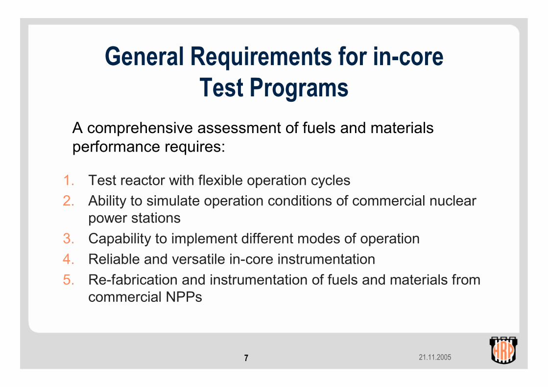
General Requirements for in-coreTest Programs
1. Test reactor with flexible operation cycles2. Ability to simulate operation conditions of commercial nuclear
power stations3. Capability to implement different modes of operation4. Reliable and versatile in-core instrumentation5. Re-fabrication and instrumentation of fuels and materials from
commercial NPPs
A comprehensive assessment of fuels and materials performance requires:
21.11.20058
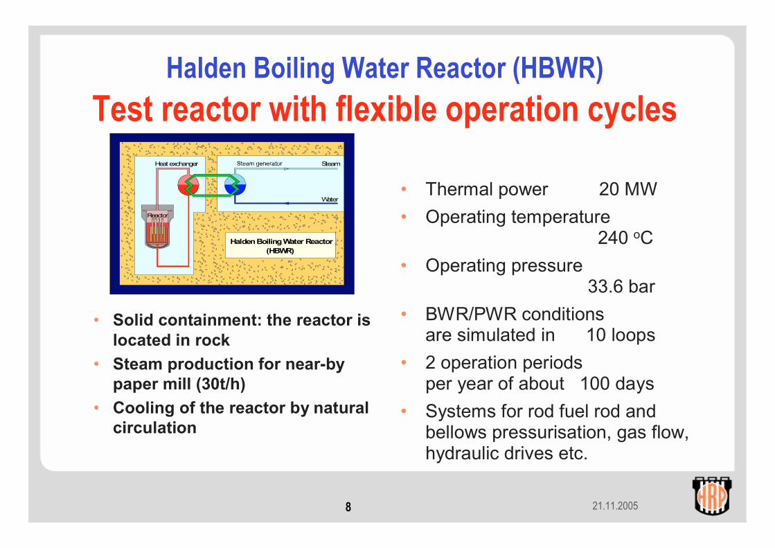
Halden Boiling Water Reactor (HBWR)Test reactor with flexible operation cycles
Heat exchanger Steam
Water
Reactor
Halden Boiling Water Reactor(HBWR)
• Thermal power 20 MW• Operating temperature
240 oC• Operating pressure
33.6 bar• BWR/PWR conditions
are simulated in 10 loops• 2 operation periods
per year of about 100 days• Systems for rod fuel rod and
bellows pressurisation, gas flow, hydraulic drives etc.
• Solid containment: the reactor is located in rock
• Steam production for near-by paper mill (30t/h)
• Cooling of the reactor by natural circulation

21.11.20059
The Halden reactor - invisible in the mountainin operation – producing data and steam

21.11.200510
T2
T1
S61
10
S53
S30 S35 S47 S15
504 S39 S26 16 E06 17 DO4 S65
S60 31 S33 647 32 654 S49 33 S28
515 648 22 E01 E02 23 D01D02
552 S23 21 S45 S38 11 638 603 D10 S36616
642 30 641 S75 S57 D11 12 604 S17 34 S50
35 S52 640 20 602 ECCS 557 25 S32 597 24
S63 39 626 548 15 590 628 S34 E04 645 D09
S54 S51 29 S22 630 14 503 E08 26 E05 S81
S48 S42 S44 28 617 639 27 644 E07 S62 S58
S82 S64 38 S40 636 37 637 D03 36 S21
633 S55 19 S76 S18 18 595 625
13 651 652 S46 S78 D08 S79
S73 S83
S31
D05 610
S56
S77
S27 S84
S80 S59
D06
E03 C04
S37
D07 C03
• More than 300 positions individually accessible
• About 110 positions in central core
• About 30 positions for experimental purposes(any of 110/300)
• Height of active core 80cm• Usable length within moderator
about 160cm• Experimental channel Ø:
- 70mm in HBWR moderator- 35-45mm in pressure flask
• Loop systems for simulation of typical thermal-hydraulic and chemistry conditions
HBWR Core Configuration
21.11.200511
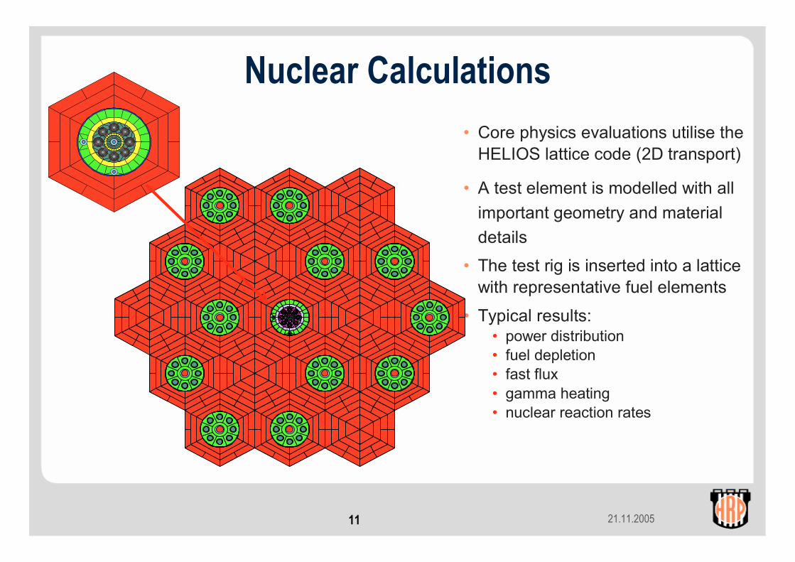
• Core physics evaluations utilise the HELIOS lattice code (2D transport)
• A test element is modelled with all important geometry and material details
• The test rig is inserted into a lattice with representative fuel elements
• Typical results:• power distribution• fuel depletion• fast flux• gamma heating• nuclear reaction rates
Nuclear Calculations

21.11.200512
• Thermal power 20 MW• Heavy water moderated and cooled
(240 oC, 33.6 bar)• Thermal neutron flux
• 1 - 5·1013 n/cm2
• 1.4·1014 in ramp configuration
• Fast neutron flux• 0.5 - 3.0·1013 depending on position
and local power• 4 - 6·1013 in high power booster rigs
0
.02
.04
.06
.08
.1
.12
.14
.16
.18
0.01 0.1 1 10 102 103 104 105 106
standard fuel
booster fuel
empty channel
Neutron Energy (eV)
Frac
tiona
l flu
x sp
ectru
m p
er u
nit l
etha
rgy
HBWR Nuclear Characteristics
21.11.200513
Application of Halden data• Provide data for fuel behaviour model
development, verification and validation• Define starting conditions of transients and to
assess the further developments• Show compliance of fuel performance with design,
operational and safety criteria• Assess safety criteria with respect to available
margins and reasonableness
21.11.200514
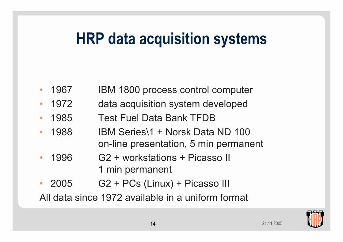
HRP data acquisition systems
• 1967 IBM 1800 process control computer• 1972 data acquisition system developed• 1985 Test Fuel Data Bank TFDB• 1988 IBM Series\1 + Norsk Data ND 100
on-line presentation, 5 min permanent• 1996 G2 + workstations + Picasso II
1 min permanent• 2005 G2 + PCs (Linux) + Picasso IIIAll data since 1972 available in a uniform format
21.11.200515
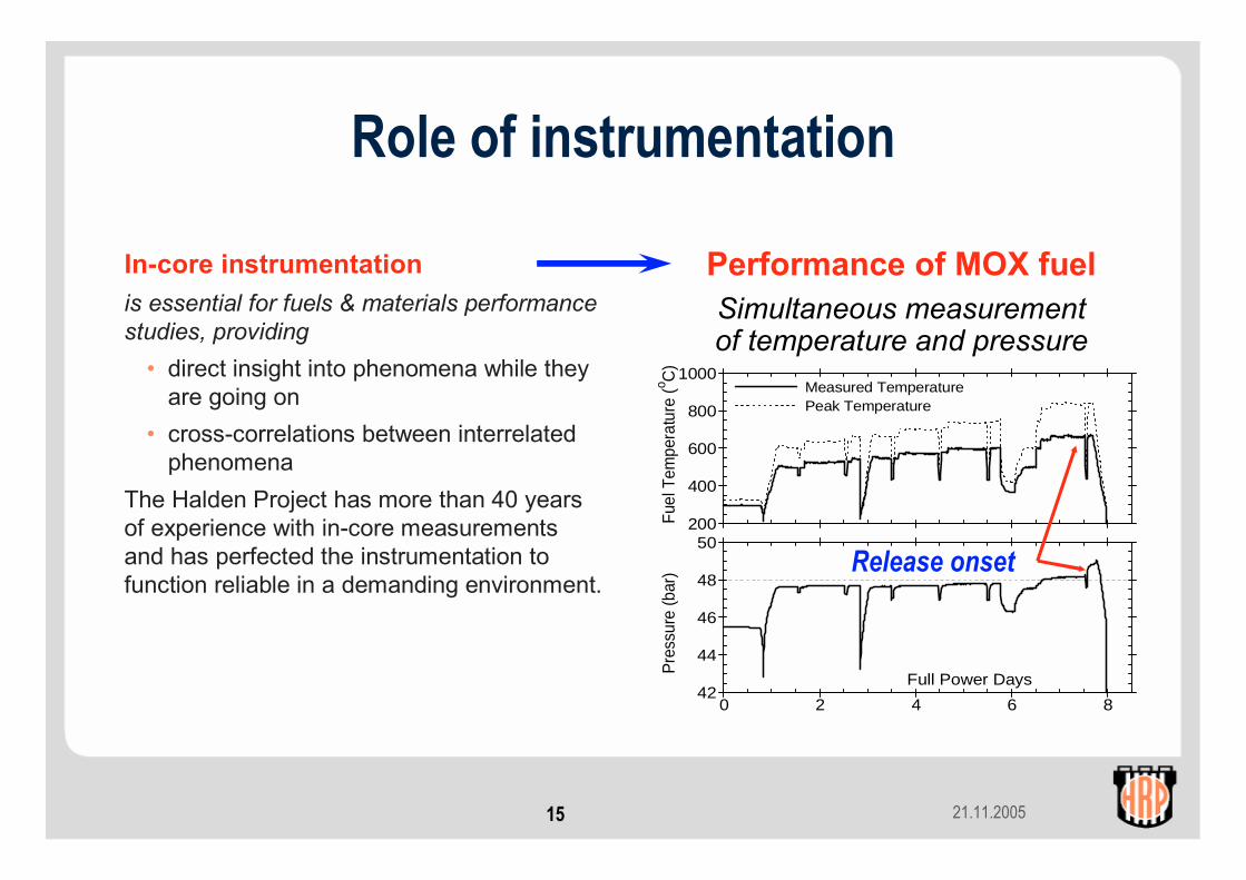
Role of instrumentation
In-core instrumentationis essential for fuels & materials performance studies, providing
• direct insight into phenomena while they are going on
• cross-correlations between interrelated phenomena
The Halden Project has more than 40 years of experience with in-core measurements and has perfected the instrumentation to function reliable in a demanding environment.
0 2 4 6 842
44
46
48
50200
400
600
800
1000
Fuel
Tem
pera
ture
(o C)
Pre
ssur
e (b
ar)
Full Power Days
Measured Temperature Peak Temperature
Performance of MOX fuelSimultaneous measurementof temperature and pressure
Release onset

21.11.200516
Basic in-core measurements, fuelPrimary Measurements• Fuel temperature• Rod pressure (fission gas release)• Fuel stack length change• Clad elongation (PCMI)• Clad diameter• Gap meter (squeezing technique)• Neutron flux / powerSecondary Measurements• Hydraulic diameter• Gamma spectrometry (FGR)
21.11.200517
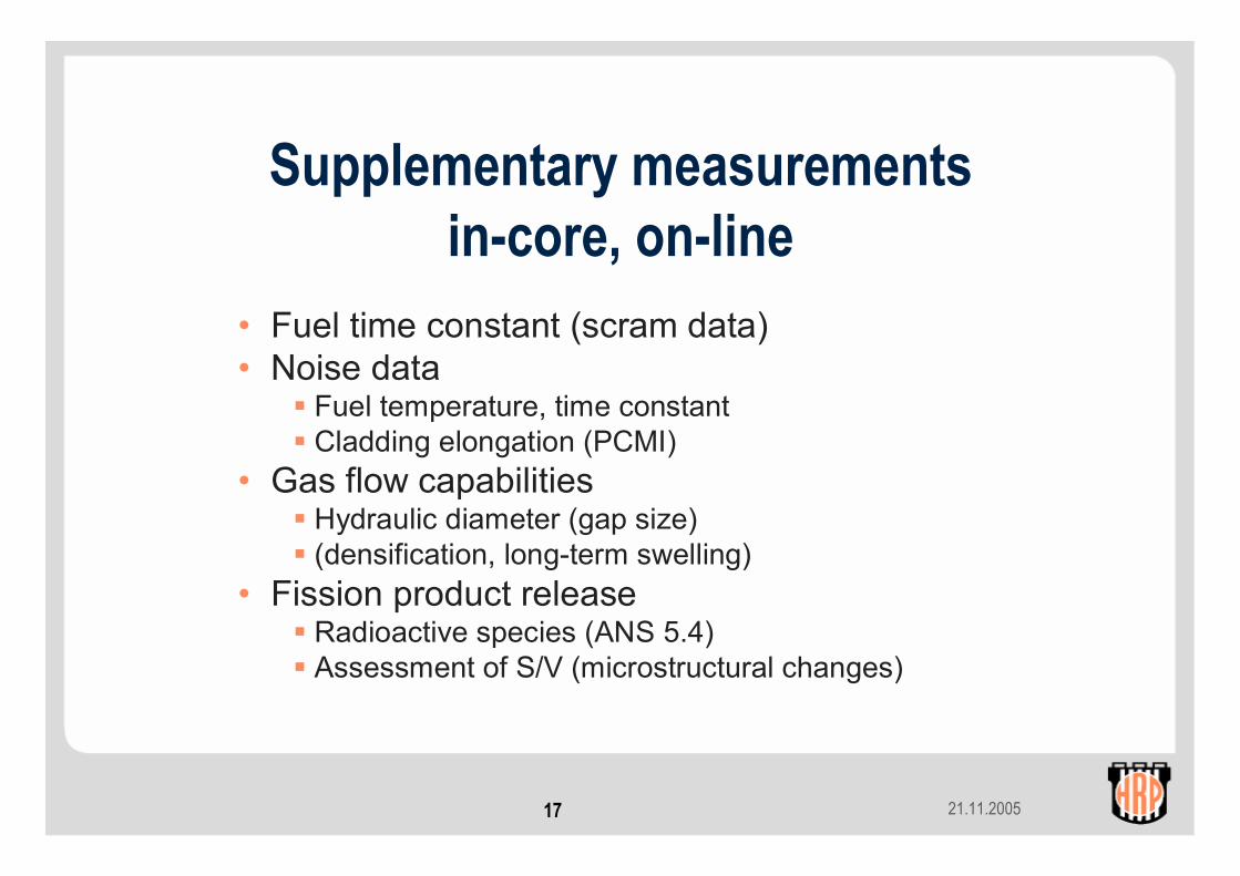
Supplementary measurementsin-core, on-line
• Fuel time constant (scram data)• Noise data
Fuel temperature, time constantCladding elongation (PCMI)
• Gas flow capabilitiesHydraulic diameter (gap size)(densification, long-term swelling)
• Fission product releaseRadioactive species (ANS 5.4)Assessment of S/V (microstructural changes)
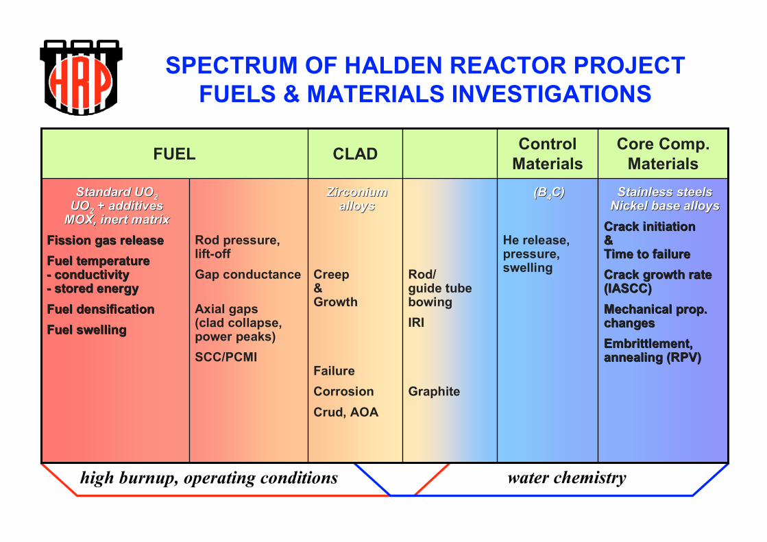
SPECTRUM OF HALDEN REACTOR PROJECT FUELS & MATERIALS INVESTIGATIONS
high burnup, operating conditions water chemistry
StainlessStainless steelssteelsNickelNickel base base alloysalloys
CrackCrack initiationinitiation&&Time to Time to failurefailureCrackCrack growthgrowth rate rate (IASCC)(IASCC)MechanicalMechanical propprop. . changeschangesEmbrittlementEmbrittlement,,annealingannealing (RPV)(RPV)
(B(B44C)C)
He release,pressure,swellingRod/
guide tube bowingIRI
Graphite
ZirconiumZirconiumalloysalloys
Creep&Growth
FailureCorrosionCrud, AOA
Rod pressure,lift-offGap conductance
Axial gaps(clad collapse,power peaks)SCC/PCMI
Standard UOStandard UO22UOUO22 + additives+ additives
MOX, inert MOX, inert matrixmatrixFissionFission gas gas releasereleaseFuelFuel temperaturetemperature-- conductivityconductivity-- storedstored energyenergyFuelFuel densificationdensificationFuelFuel swellingswelling
Core Comp. Materials
ControlMaterialsCLADFUEL
21.11.200519
Contents1. Instruments and techniques for flux monitoring / control
a. Gamma flux measurementsb. Neutron flux measurementsc. Flux shielding / flux depression
• He-3 coils• Moveable neutron shields
21.11.200520
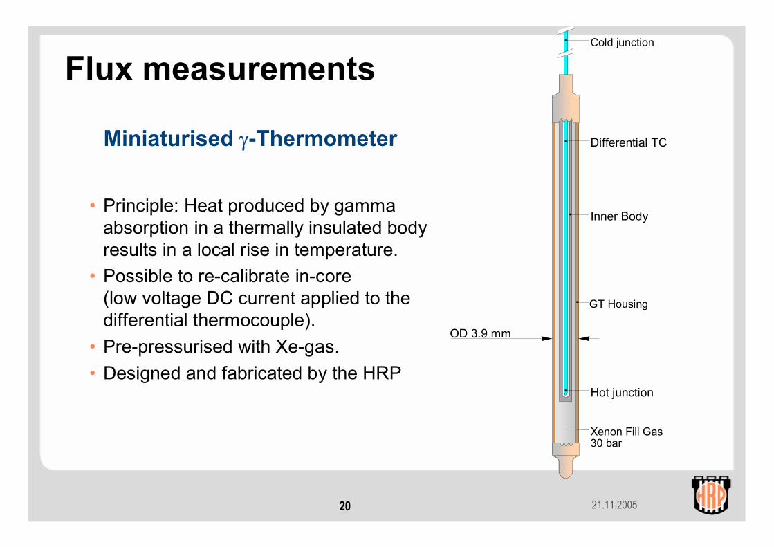
Differential TC
Inner Body
GT Housing
Xenon Fill Gas30 bar
Hot junction
Cold junction
OD 3.9 mm
Miniaturised γ-Thermometer
• Principle: Heat produced by gamma absorption in a thermally insulated body results in a local rise in temperature.
• Possible to re-calibrate in-core (low voltage DC current applied to the differential thermocouple).
• Pre-pressurised with Xe-gas. • Designed and fabricated by the HRP
Flux measurements
21.11.200521
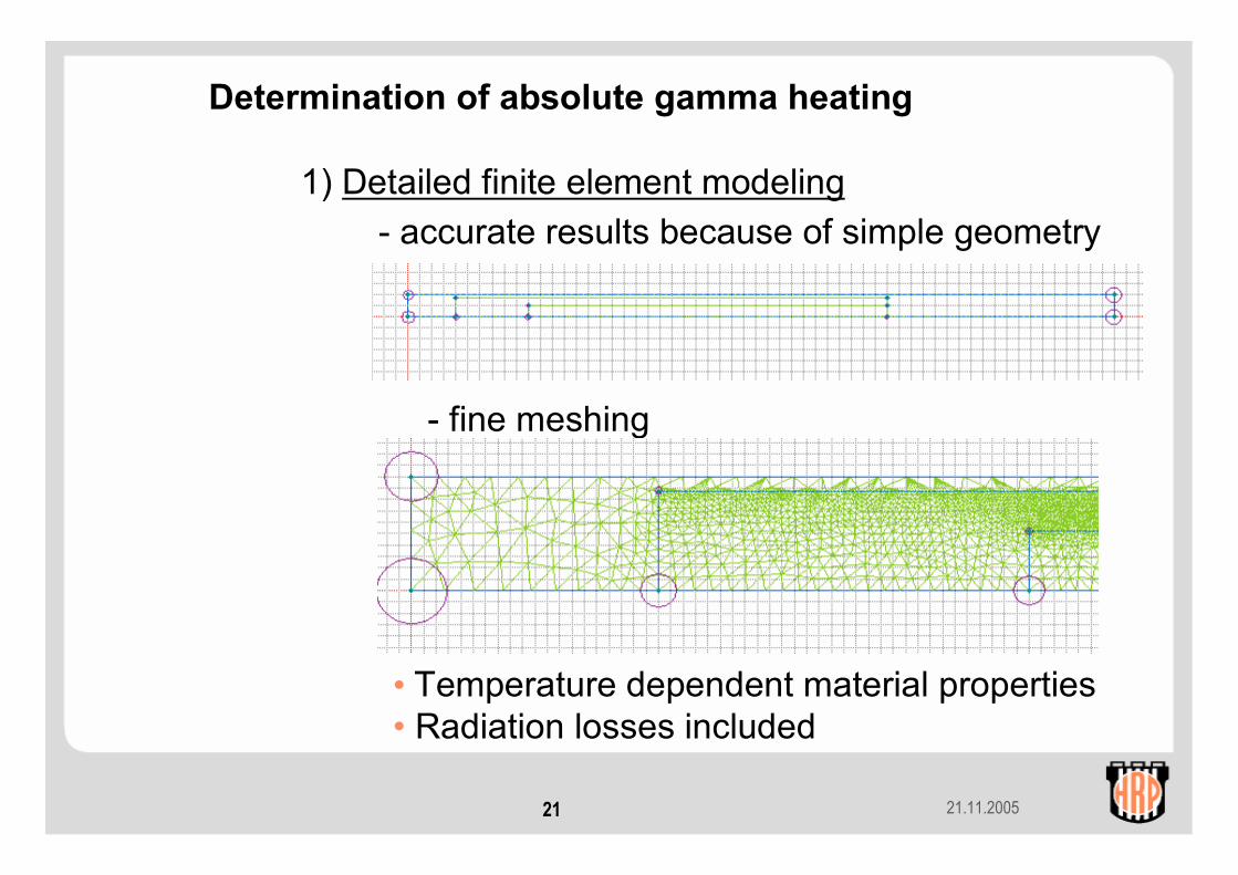
Determination of absolute gamma heating
1) Detailed finite element modeling- accurate results because of simple geometry
- fine meshing
• Temperature dependent material properties• Radiation losses included
21.11.200522
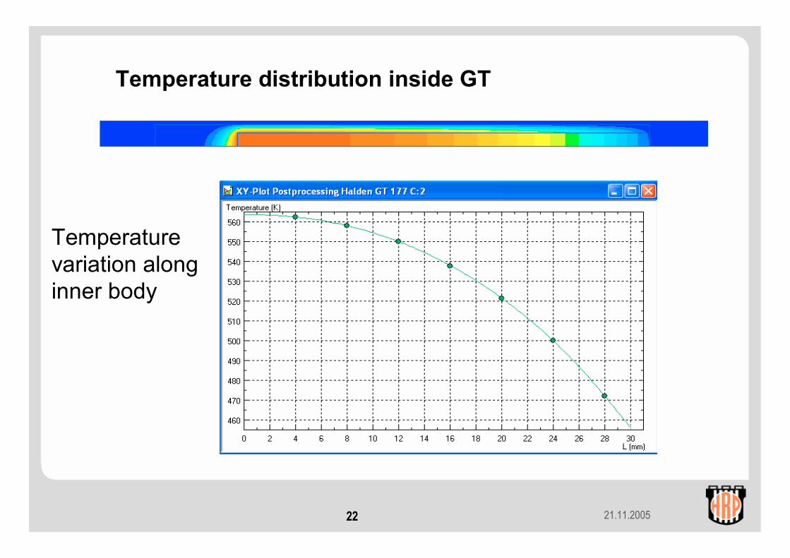
Temperature distribution inside GT
Temperaturevariation along inner body

21.11.200523
2) In-pile calibrations (experimental/theoretical)
How ? - Heat GT inner body by sending a currentthrough the thermocouple
- Switch off heating current- Record the decay of the temperature- Use relation between time constant and
sensitivity (based on theory !)
320
330
340
350
360
370
0 50 100 150 200
Time (s)
Tem
pera
ture
(C)
Decay time = 39.7 s
21.11.200524
Emitter
Al2O3 Powder
Housing
Helium Fill Gas
MI Cable
OD 3.5 mm
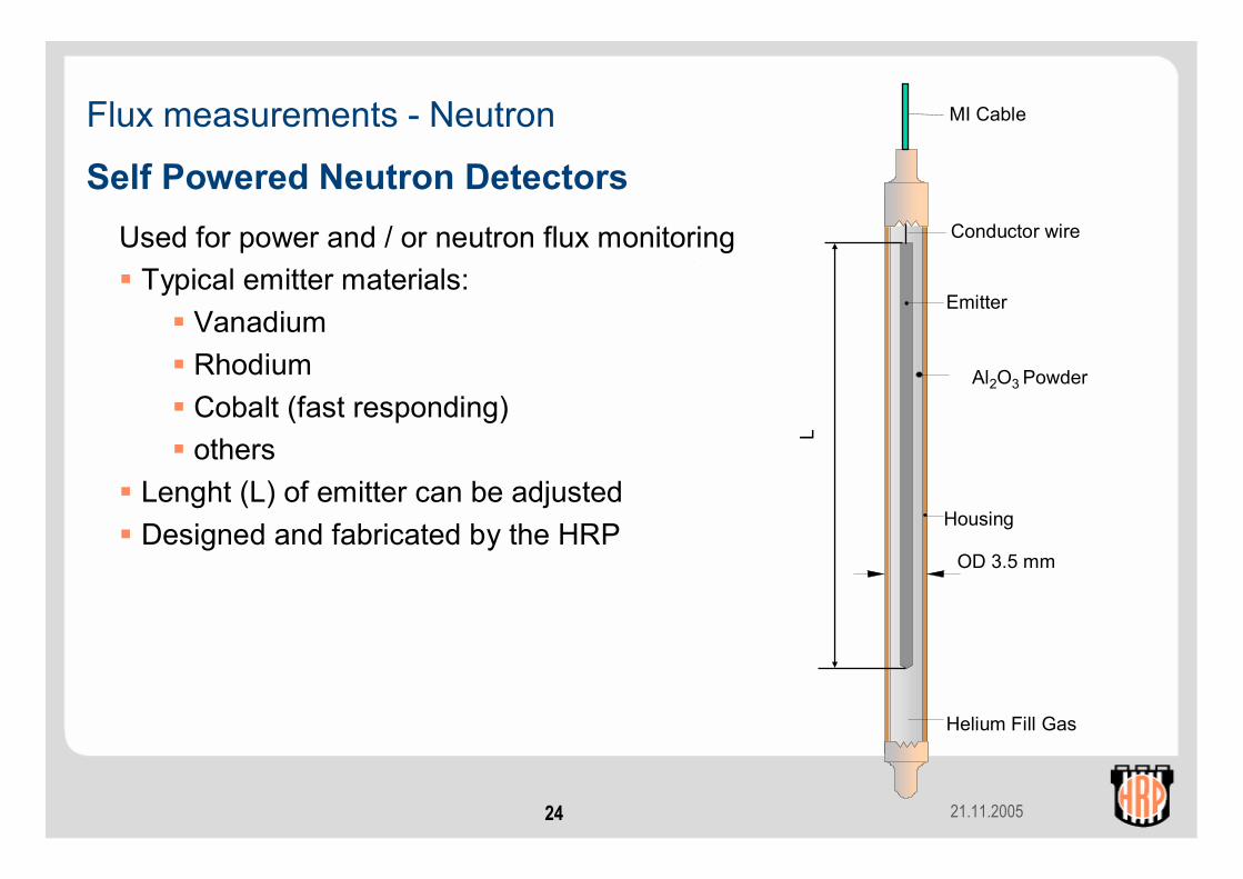
Self Powered Neutron DetectorsUsed for power and / or neutron flux monitoring
Typical emitter materials:Vanadium RhodiumCobalt (fast responding)others
Lenght (L) of emitter can be adjusted Designed and fabricated by the HRP
L
Conductor wire
Flux measurements - Neutron
21.11.200525
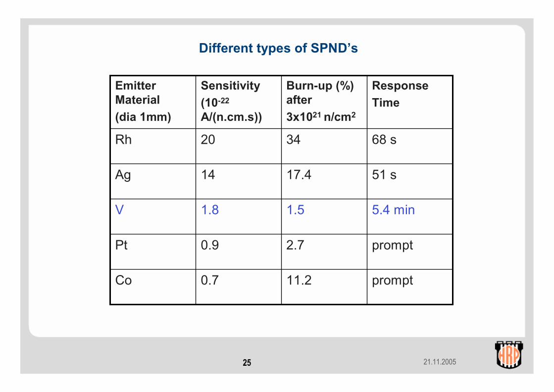
prompt11.20.7Co
prompt2.70.9Pt
5.4 min1.51.8V
51 s17.414Ag
68 s3420Rh
ResponseTime
Burn-up (%) after 3x10²¹ n/cm2
Sensitivity(10-22
A/(n.cm.s))
Emitter Material(dia 1mm)
Different types of SPND’s
21.11.200526
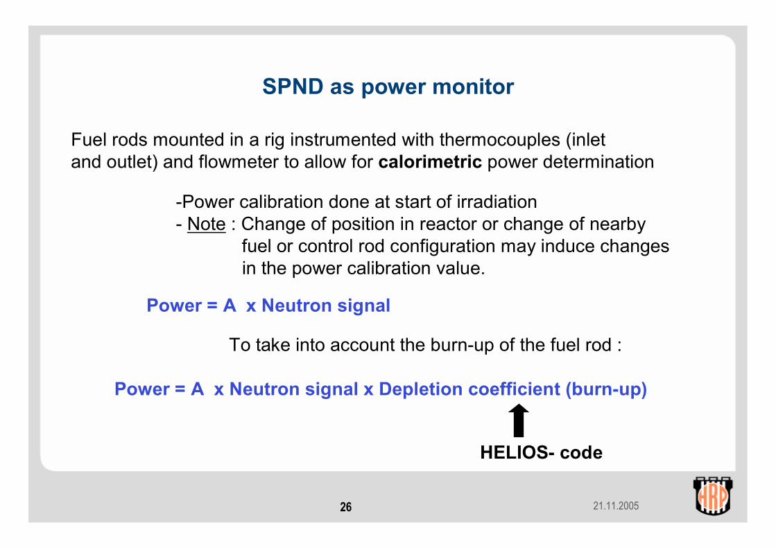
SPND as power monitor
Fuel rods mounted in a rig instrumented with thermocouples (inletand outlet) and flowmeter to allow for calorimetric power determination
Power = A x Neutron signal
-Power calibration done at start of irradiation- Note : Change of position in reactor or change of nearby
fuel or control rod configuration may induce changesin the power calibration value.
To take into account the burn-up of the fuel rod :
Power = A x Neutron signal x Depletion coefficient (burn-up)
HELIOS- code
21.11.200527
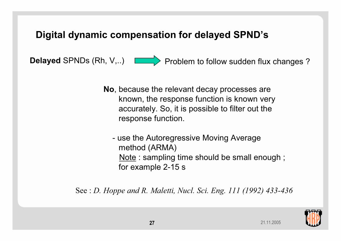
Digital dynamic compensation for delayed SPND’s
Delayed SPNDs (Rh, V,..) Problem to follow sudden flux changes ?
No, because the relevant decay processes are known, the response function is known very accurately. So, it is possible to filter out the response function.
- use the Autoregressive Moving Average method (ARMA)Note : sampling time should be small enough ; for example 2-15 s
See : D. Hoppe and R. Maletti, Nucl. Sci. Eng. 111 (1992) 433-436

21.11.200528
Raw and compensated V SPND signal with sudden flux rise at 0.41 min.With sampling time of 5 s : Response time (95 %) reduced from 16 m to 15 s
Digital compensation of V-SPND
0
0.2
0.4
0.6
0.8
1
1.2
0 0.5 1 1.5 2 2.5 3 3.5 4 4.5 5
Time (min)
Sign
al
I_SPND ARMA
Note : The same procedure can of course be applied also forGamma thermometer !

21.11.200529
Contents (contd.)2. Fuel rod instrumentation:
a. Thermocouples• Fuel temperature• Cladding temperature
b. The Linear Voltage Differential Transformer (LVDT)• Fuel stack elongation detector EF• Cladding extensometer EC • Fuel rod pressure transducer PF• Expansion thermometer ET (average fuel centre temperature)
c. Fuel rod gas flow/pressure lines • Radioactive fission gas release, gas flow and overpressure
d. Re-instrumentation techniques
21.11.200530
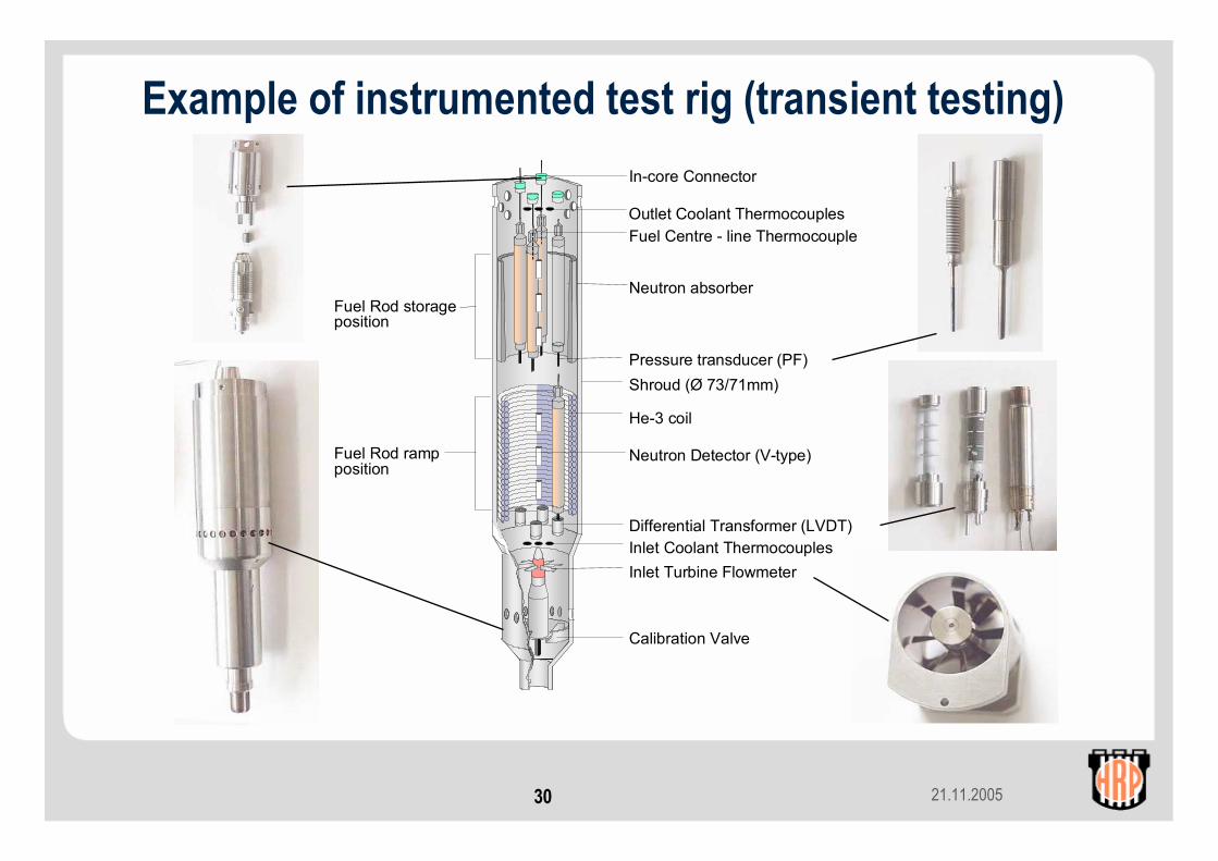
In-core Connector
Outlet Coolant ThermocouplesFuel Centre - line Thermocouple
Neutron absorber
Pressure transducer (PF)
He-3 coil
Neutron Detector (V-type)
Differential Transformer (LVDT)Inlet Coolant ThermocouplesInlet Turbine Flowmeter
Shroud (Ø 73/71mm)
Calibration Valve
Fuel Rod storageposition
Fuel Rod rampposition
Example of instrumented test rig (transient testing)

21.11.200531
Fuel rod instrumentationThermocouples• Fuel T• Cladding TLVDT principle• Temperature• Elongation
• fuel stack elongation • cladding elongation
• Pressure (fission gas)Gas Lines• Adjust rod pressure (e.g. overpressure)• Fuel-clad gap
• hydraulic diameter (swelling)• gap conductance (change gas mixture)
• Radioactive fission gas release
Relevant to fuel performance
Validation of models
21.11.200532
Fuel temperature
• Gap conductance• Gap width• Surface roughness• Eccentricity• Gas composition (FISSION GAS RELEASE)
• Pellet• Densification and swelling (indirect)• Thermal conductivity (degradation)
With fuel thermocouples, fuel centreline temperatures can be measured accurately and reliably for temperatures up to ~1500 - 1600°C. For short-term measurements (hours) temperatures even as high as ~2000 °C have been measured without thermocouple failure.Fuel centreline thermocouples (TF) enable modellers to compare their code predictions with measurements:

21.11.200533
Variation of gap sizeThe gap between fuel and cladding is a design parameter and in addition changes with exposure. Numerous HRP experiments provide an extensive data base for assessing the basic influence of gap size on gap conductance. The general trend is summarised in the graph on the right for Helium and Xenon as fill gas.
Influence of gap on fuel temperature
0 .1 .2 .3 .4 .5400
600
800
1000
1200
1400
1600
As fabricated gap, mm F
uel
cent
re te
mper
atur
e, o
C
Helium20 kW/m
Helium30 kW/m
Xenon 20 kW/m
21.11.200534
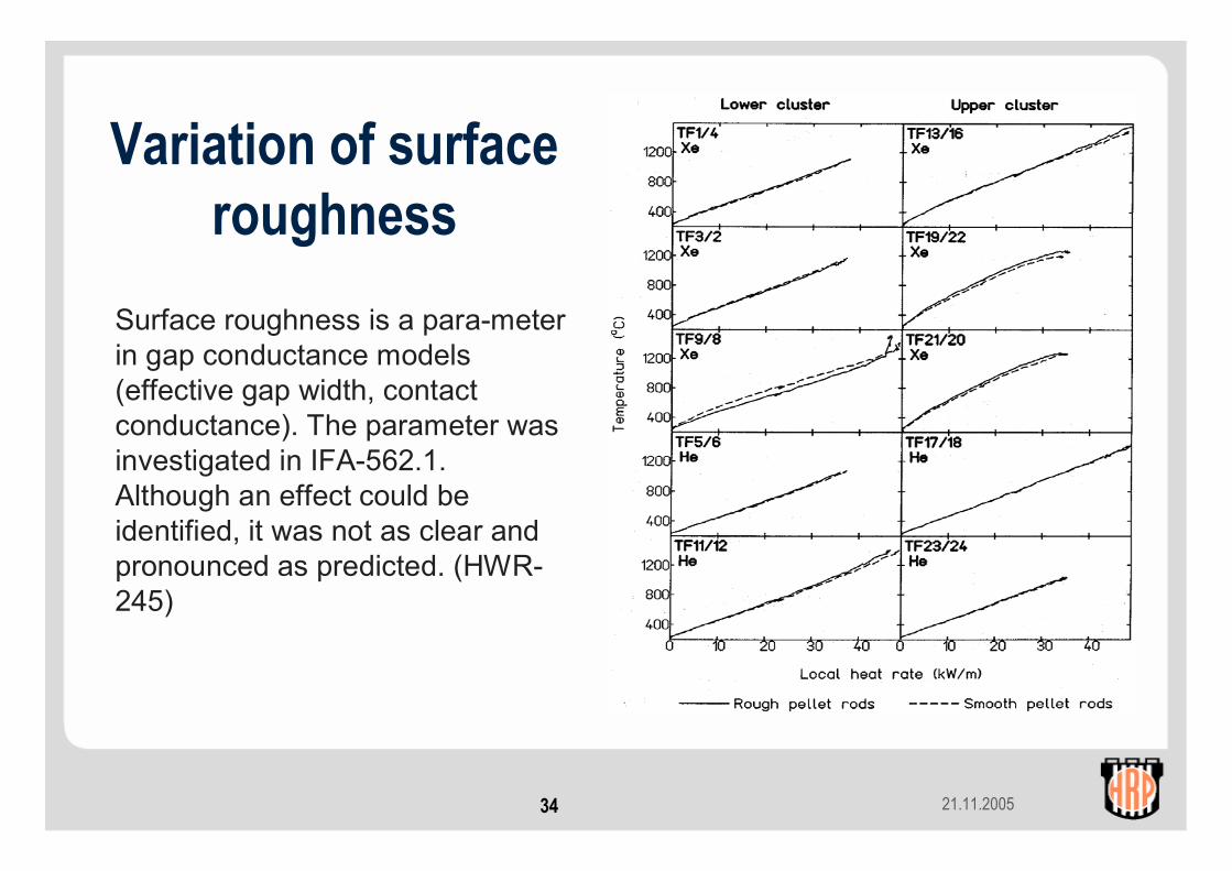
Variation of surface roughness
Surface roughness is a para-meter in gap conductance models (effective gap width, contact conductance). The parameter was investigated in IFA-562.1. Although an effect could be identified, it was not as clear and pronounced as predicted. (HWR-245)
21.11.200535
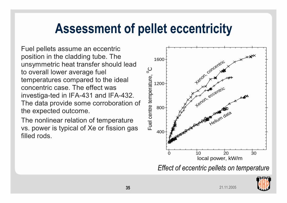
Assessment of pellet eccentricityFuel pellets assume an eccentric position in the cladding tube. The unsymmetric heat transfer should lead to overall lower average fuel temperatures compared to the ideal concentric case. The effect was investiga-ted in IFA-431 and IFA-432. The data provide some corroboration of the expected outcome.The nonlinear relation of temperature vs. power is typical of Xe or fission gas filled rods.
0 10 20 30
400
800
1200
1600
local power, kW/m
Fuel
cen
tre te
mpe
ratu
re, o C
Xenon
, conce
ntric
Xenon, eccentric
Helium data
Effect of eccentric pellets on temperature

21.11.200536
Fill gas type and compositionThe initial fuel rod helium fill gas is diluted by released fission gas resulting in decreased gap con-ductance. The effect and the feedback on temperatures and further gas release needs accurate modelling. A number of experiments were conducted in the past where xenon or argon were added to simulate various degrees of fission gas release. The results from several IFAs are summarised in the figure.
Influence of fill gas on fuel temperature
0 25 50 75 100400
800
1200
1600
2000
initial Xenon content, % Fu
el c
entre
tem
pera
ture
, o C
30 kW/m
20 kW/m
21.11.200537
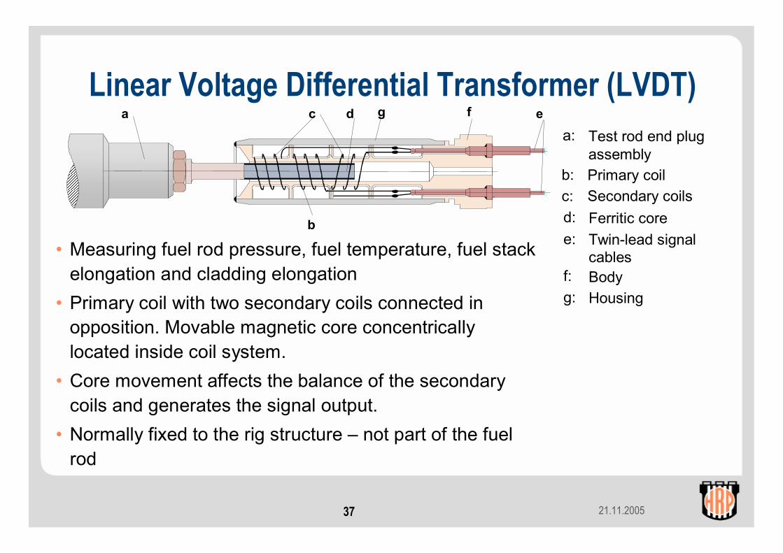
Linear Voltage Differential Transformer (LVDT)
• Measuring fuel rod pressure, fuel temperature, fuel stack elongation and cladding elongation
• Primary coil with two secondary coils connected in opposition. Movable magnetic core concentrically located inside coil system.
• Core movement affects the balance of the secondary coils and generates the signal output.
• Normally fixed to the rig structure – not part of the fuel rod
a c d
b
eg f
Test rod end plug assemblyPrimary coilSecondary coilsFerritic coreTwin-lead signalcablesBodyHousing
a:
b:c:d:e:
f:g:

21.11.200538
Linear Voltage Differential Transformer (LVDT)
21.11.200539
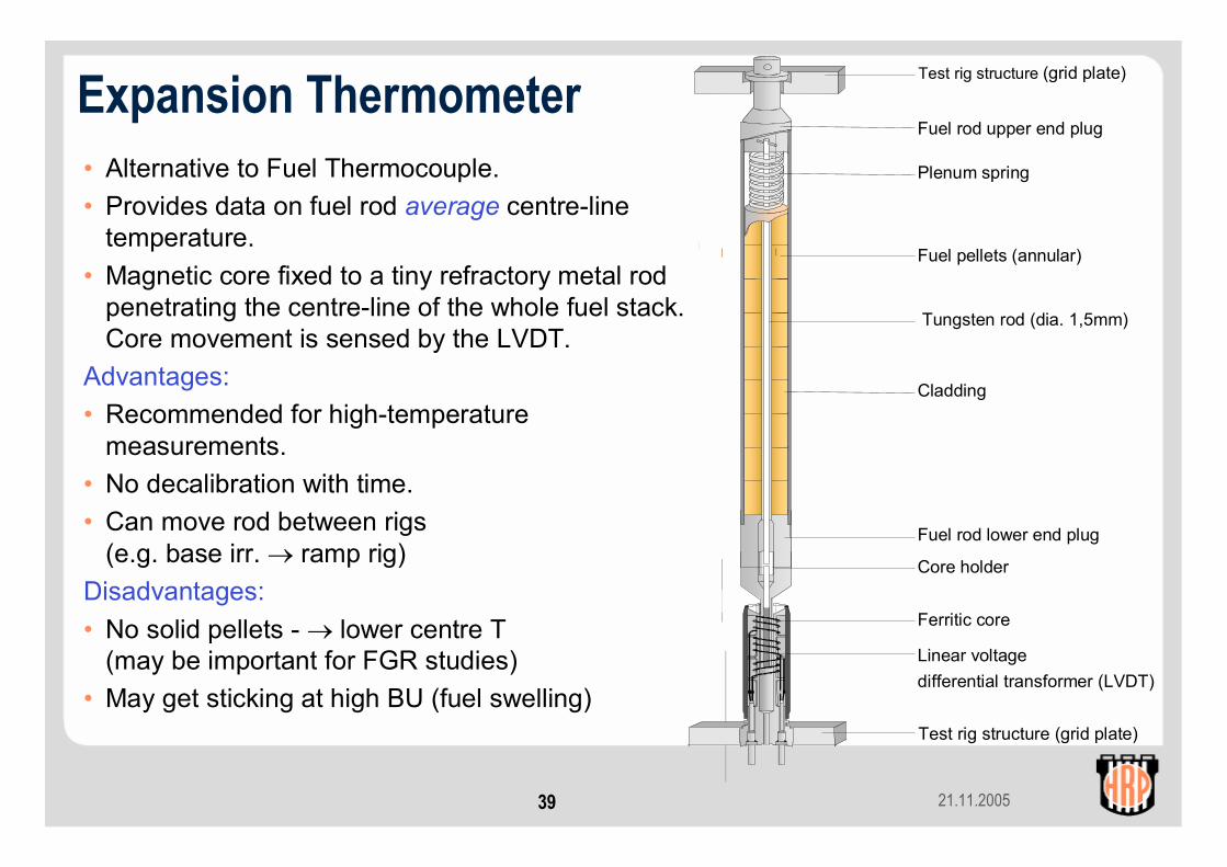
Expansion Thermometer• Alternative to Fuel Thermocouple.• Provides data on fuel rod average centre-line
temperature.• Magnetic core fixed to a tiny refractory metal rod
penetrating the centre-line of the whole fuel stack. Core movement is sensed by the LVDT.
Advantages:• Recommended for high-temperature
measurements.• No decalibration with time.• Can move rod between rigs
(e.g. base irr. → ramp rig)Disadvantages:• No solid pellets - → lower centre T
(may be important for FGR studies)• May get sticking at high BU (fuel swelling)
Test rig structure (grid plate)
Fuel rod upper end plug
Plenum spring
Fuel pellets (annular)
Tungsten rod (dia. 1,5mm)
Cladding
Fuel rod lower end plug
Core holder
Ferritic core
Linear voltagedifferential transformer (LVDT)
Test rig structure (grid plate)
21.11.200540
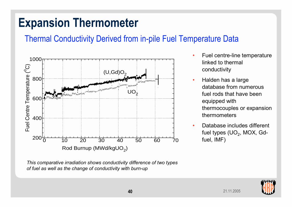
Thermal Conductivity Derived from in-pile Fuel Temperature Data• Fuel centre-line temperature
linked to thermal conductivity
• Halden has a large database from numerous fuel rods that have been equipped with thermocouples or expansion thermometers
• Database includes different fuel types (UO2, MOX, Gd-fuel, IMF)0 10 20 30 40 50 60 70200
400
600
800
1000
Rod Burnup (MWd/kgUO2)
Fuel
Cen
tre T
empe
ratu
re (o C
)
UO2
(U,Gd)O2
This comparative irradiation shows conductivity difference of two types of fuel as well as the change of conductivity with burn-up
Expansion Thermometer
21.11.200541
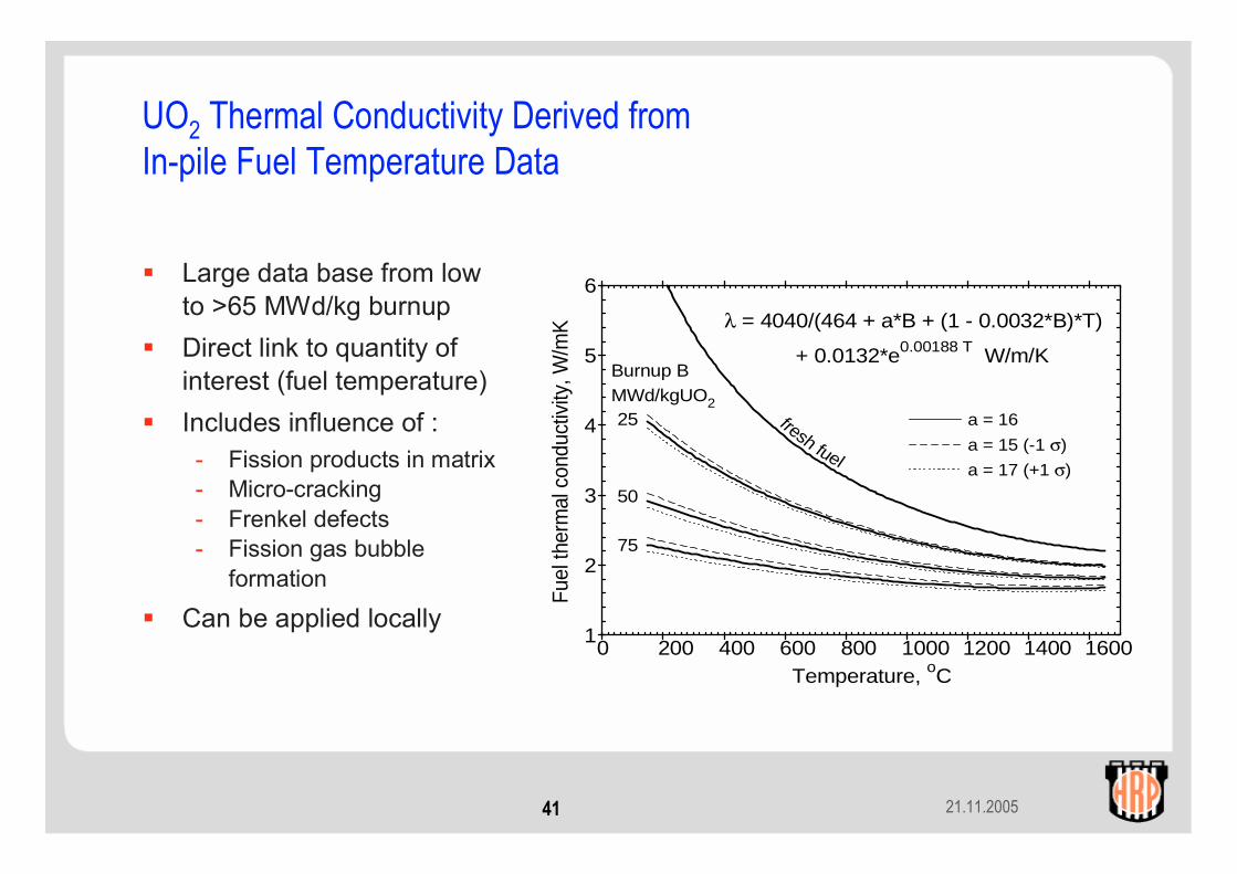
UO2 Thermal Conductivity Derived fromIn-pile Fuel Temperature Data
Large data base from low to >65 MWd/kg burnupDirect link to quantity of interest (fuel temperature)Includes influence of :- Fission products in matrix- Micro-cracking- Frenkel defects- Fission gas bubble
formation
Can be applied locally0 200 400 600 800 1000 1200 1400 1600
1
2
3
4
5
6
λ = 4040/(464 + a*B + (1 - 0.0032*B)*T)
+ 0.0132*e0.00188 T W/m/K
Temperature, oC
Fuel
ther
mal
con
duct
ivity
, W/m
K
a = 16
a = 15 (-1 σ)
a = 17 (+1 σ)
Burnup B MWd/kgUO2
fresh fuel
25
50
75

21.11.200542
Linear voltagedifferentialtransformer (LVDT)
Magnetic core
Support formagnetic coreEnd plug
Spring
Fuel stack
Fuel Stack Elongation Detector (EF)
• Provides densification and swelling data in terms of axial expansion of the fuel stack.
• Magnetic core spring loaded against the fuel column end pellet in the rod plenum.
• Core movement measured by LVDT.
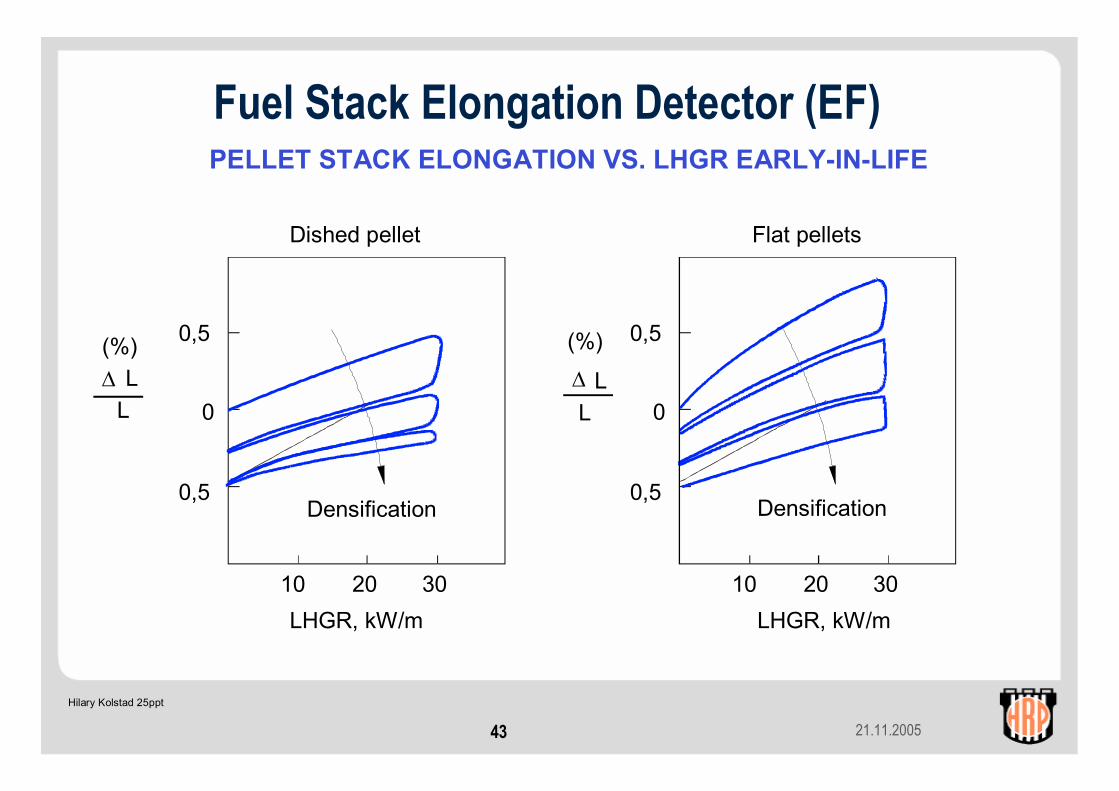
21.11.200543
PELLET STACK ELONGATION VS. LHGR EARLY-IN-LIFE
Hilary Kolstad 25ppt
(%)∆
0,5
0
0,5
10 20 30
0,5
0
0,5
10 20 30
Densification Densification
LHGR, kW/mLHGR, kW/m
(%)∆ LL
LL
Dished pellet Flat pellets
Fuel Stack Elongation Detector (EF)
21.11.200544
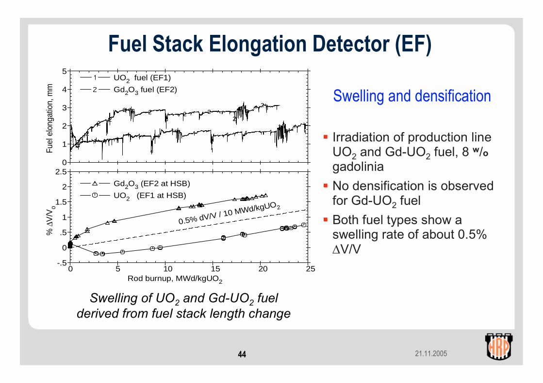
Swelling and densification
Irradiation of production line UO2 and Gd-UO2 fuel, 8 w/ogadoliniaNo densification is observed for Gd-UO2 fuelBoth fuel types show a swelling rate of about 0.5% ∆V/V
Swelling of UO2 and Gd-UO2 fuel derived from fuel stack length change
0 5 10 15 20 25-.5
0
.5
1
1.5
2
2.50
1
2
3
4
5
Rod burnup, MWd/kgUO2
% ∆
V/V
o Fu
el e
long
atio
n, m
m UO2 fuel (EF1)
Gd2O3 fuel (EF2)
Gd2O3 (EF2 at HSB)
UO2 (EF1 at HSB)
0.5% dV/V / 10 MWd/kgUO2
Fuel Stack Elongation Detector (EF)

21.11.200545
Cladding Extensometer (EC)• Provides data on pellet-cladding
interaction (PCMI) and axial deformation of the cladding.
• Movement of a magnetic core (fixed to the fuel rod end) measured by a LVDT.
• Can also be used as a point of dry-out detector or for measuring oxide layer and crud build-up(assumes no PCMI).
Test rig structure (grid plate)
Fuel rod upper end plug
Plenum spring
Fuel pellets
Cladding
Fuel rod lower end plug
Core holder
Ferritic core
Linear voltagedifferential transformer (LVDT)
Test rig structure (grid plate)
21.11.200546
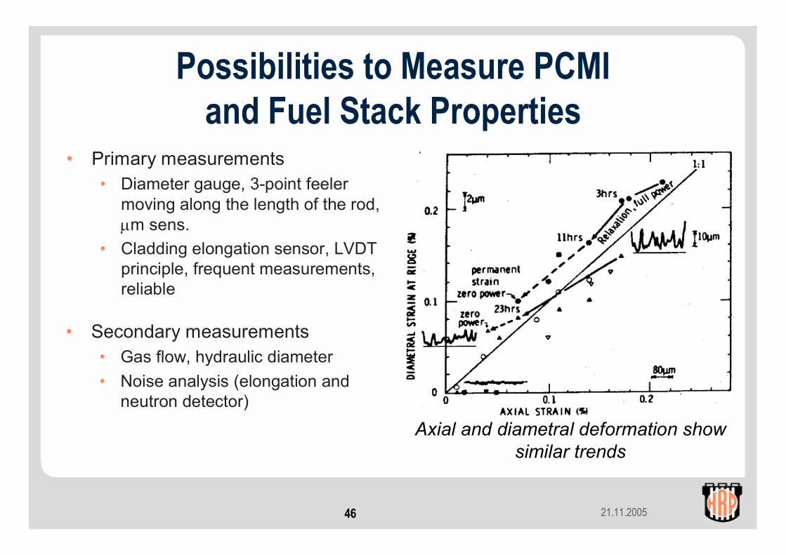
Possibilities to Measure PCMIand Fuel Stack Properties
• Primary measurements• Diameter gauge, 3-point feeler
moving along the length of the rod, µm sens.
• Cladding elongation sensor, LVDT principle, frequent measurements, reliable
Axial and diametral deformation show similar trends
• Secondary measurements• Gas flow, hydraulic diameter• Noise analysis (elongation and
neutron detector)

21.11.200547
Development of Onset of Interaction– Fresh Fuel –
Features of early-in-life PCMI• First power ramp: very early
onset of interaction• Following power ramps: shift of
PCMI onset to higher power• Relaxation of axial strain during
power holds• Immediate continuation of
elongation when power increases (strong contact)
21.11.200548
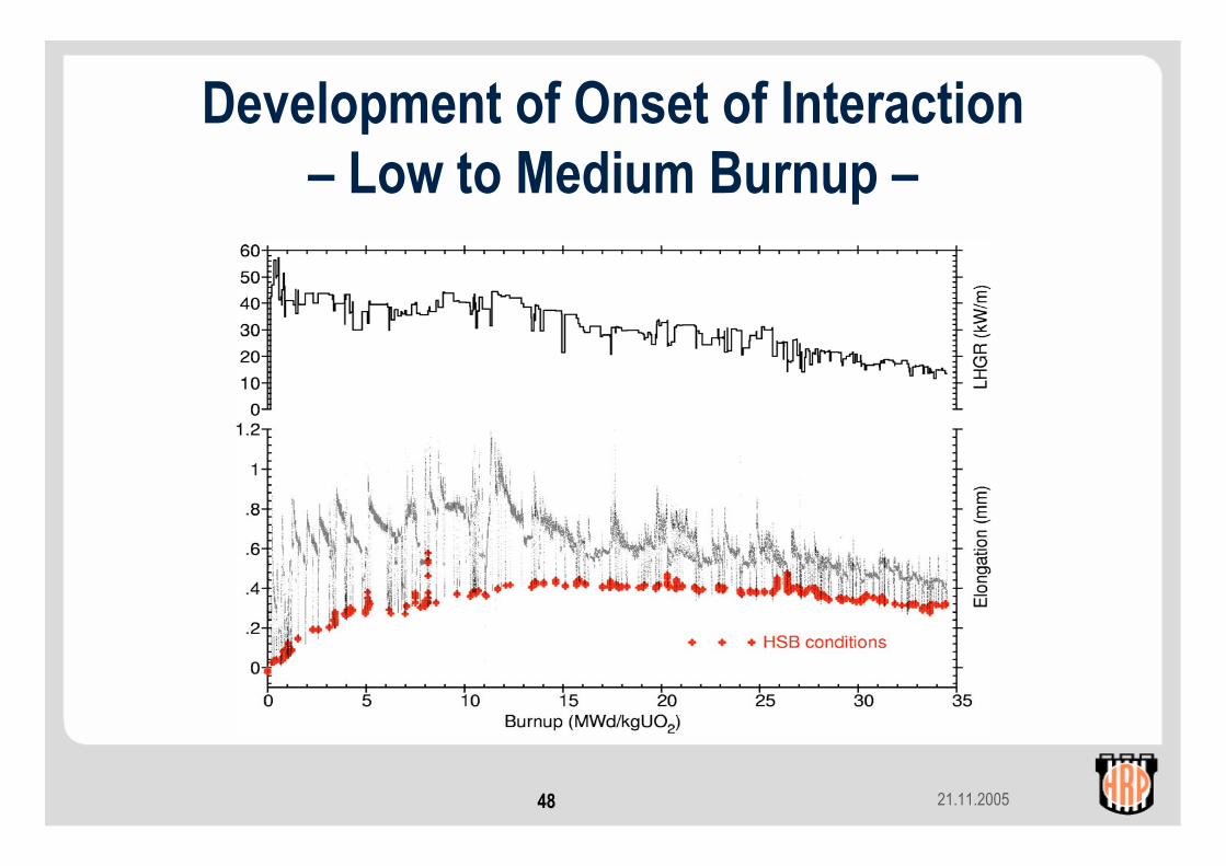
Development of Onset of Interaction– Low to Medium Burnup –
21.11.200549
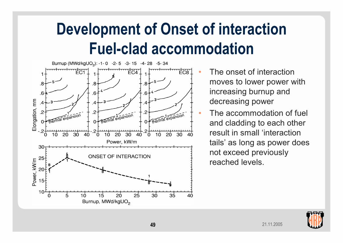
Development of Onset of interaction Fuel-clad accommodation
• The onset of interaction moves to lower power with increasing burnup and decreasing power
• The accommodation of fuel and cladding to each other result in small ‘interaction tails’ as long as power does not exceed previously reached levels.
21.11.200550
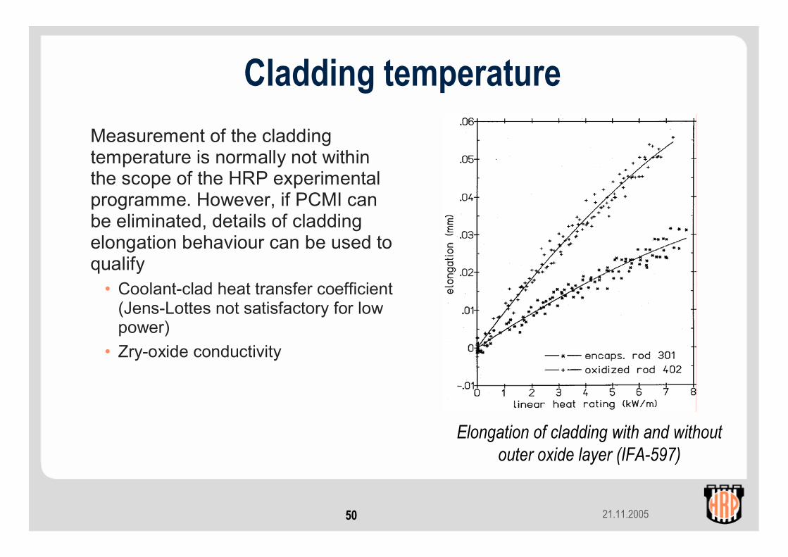
Cladding temperatureMeasurement of the cladding temperature is normally not within the scope of the HRP experimental programme. However, if PCMI can be eliminated, details of cladding elongation behaviour can be used to qualify
• Coolant-clad heat transfer coefficient (Jens-Lottes not satisfactory for low power)
• Zry-oxide conductivity
Elongation of cladding with and without outer oxide layer (IFA-597)

21.11.200551
Gas flow lines:Hydraulic diameter measurements
The hydraulic diameter reflects the free volume in the fuel column. Normal changes are:
- initial pellet cracking and fragment relocation
- solid fission product fuel swelling- development of a minimal HD as
fuel and cladding accommodate to each other
0 10 20 30 40 50 600
50
100
150
200
250
Burnup (MWd/kg UO2) Hyd
raul
ic d
iam
eter
(µm
) initial gap
gap closure with 0.7 ∆V/Vswelling per 10 MWd/kgU
Change of hydraulic diameter(free fuel column volume)
21.11.200552
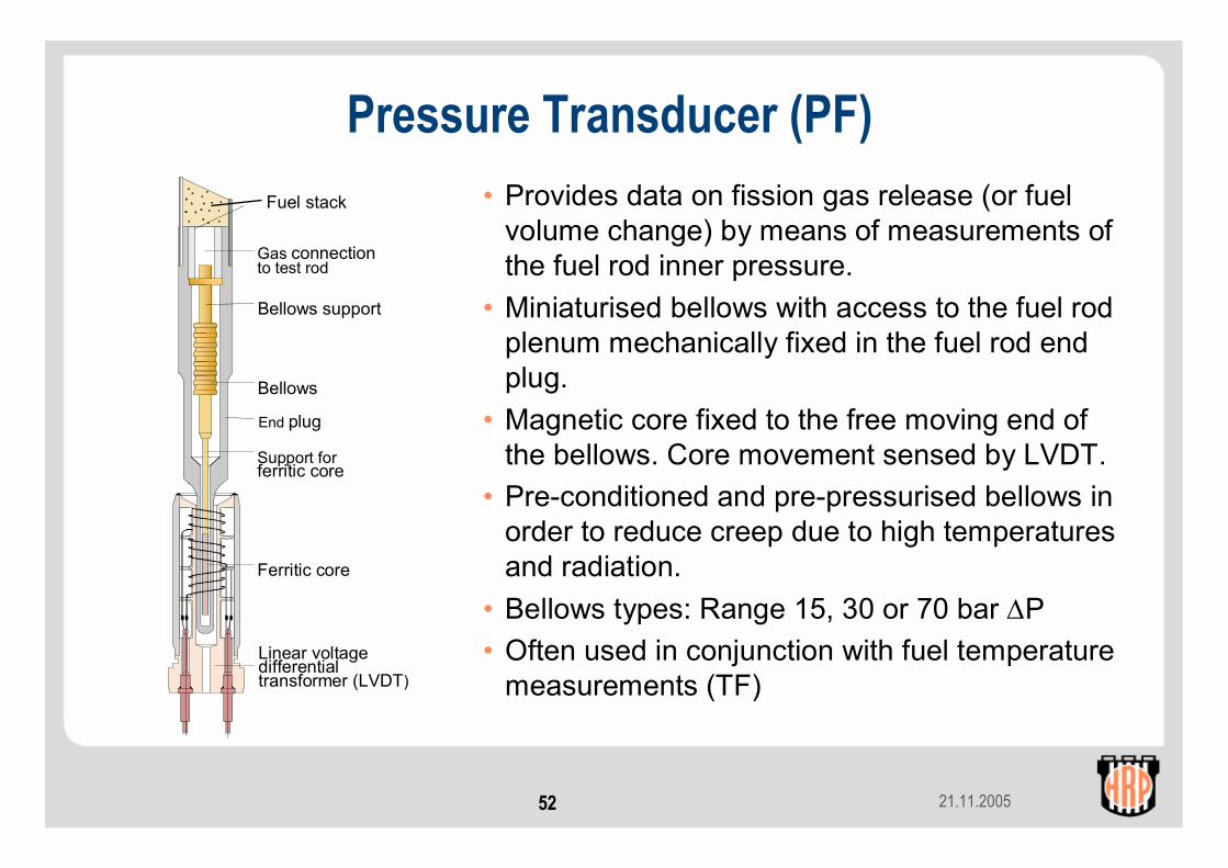
Pressure Transducer (PF)
Linear voltagedifferentialtransformer (LVDT)
Ferritic core
Support forferritic core
End plug
Bellows
Gas connectionto test rod
Bellows support
• Provides data on fission gas release (or fuel volume change) by means of measurements of the fuel rod inner pressure.
• Miniaturised bellows with access to the fuel rod plenum mechanically fixed in the fuel rod end plug.
• Magnetic core fixed to the free moving end of the bellows. Core movement sensed by LVDT.
• Pre-conditioned and pre-pressurised bellows in order to reduce creep due to high temperatures and radiation.
• Bellows types: Range 15, 30 or 70 bar ∆P• Often used in conjunction with fuel temperature
measurements (TF)
Fuel stack
21.11.200553
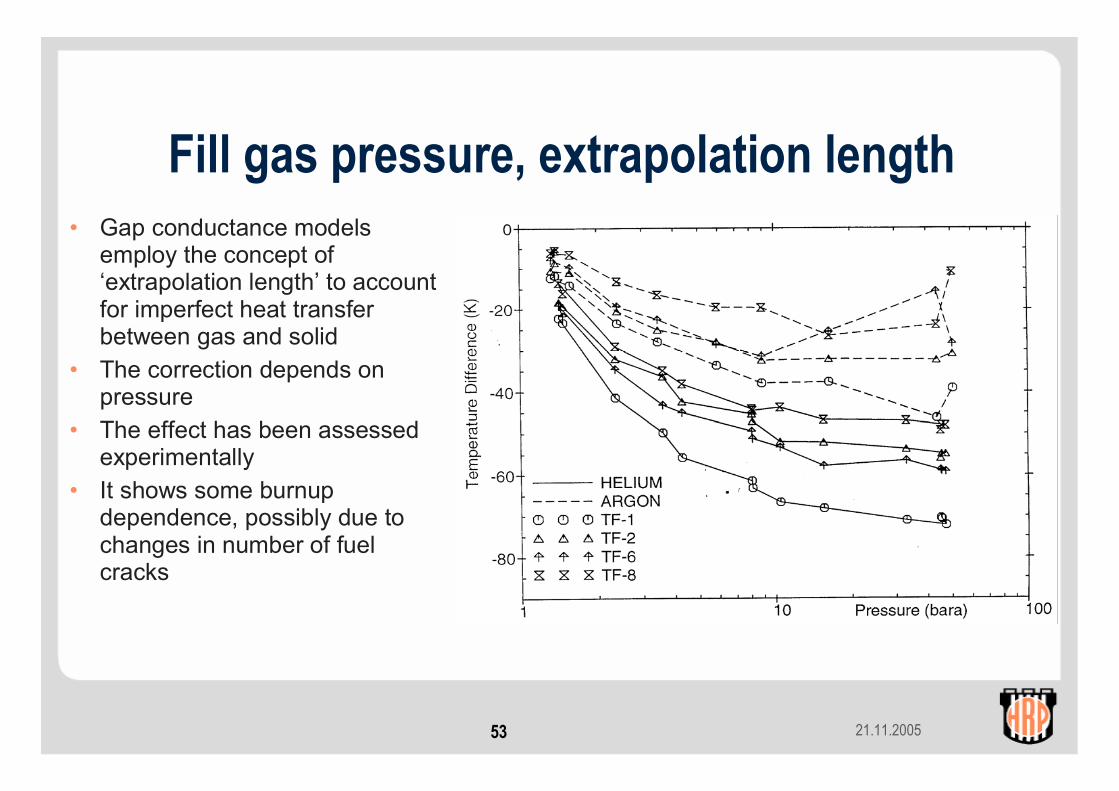
Fill gas pressure, extrapolation length• Gap conductance models
employ the concept of ‘extrapolation length’ to account for imperfect heat transfer between gas and solid
• The correction depends on pressure
• The effect has been assessed experimentally
• It shows some burnup dependence, possibly due to changes in number of fuel cracks
21.11.200554
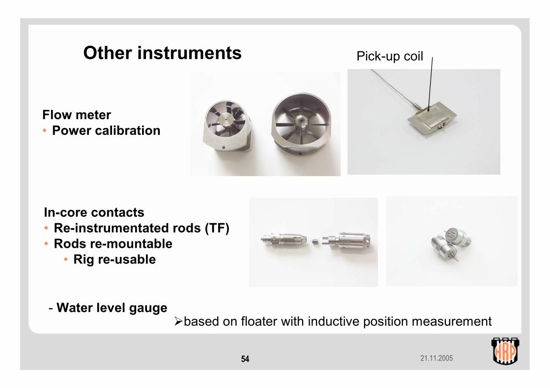
Flow meter• Power calibration
Pick-up coil
In-core contacts• Re-instrumentated rods (TF)• Rods re-mountable
• Rig re-usable
- Water level gaugebased on floater with inductive position measurement
Other instruments
21.11.200555
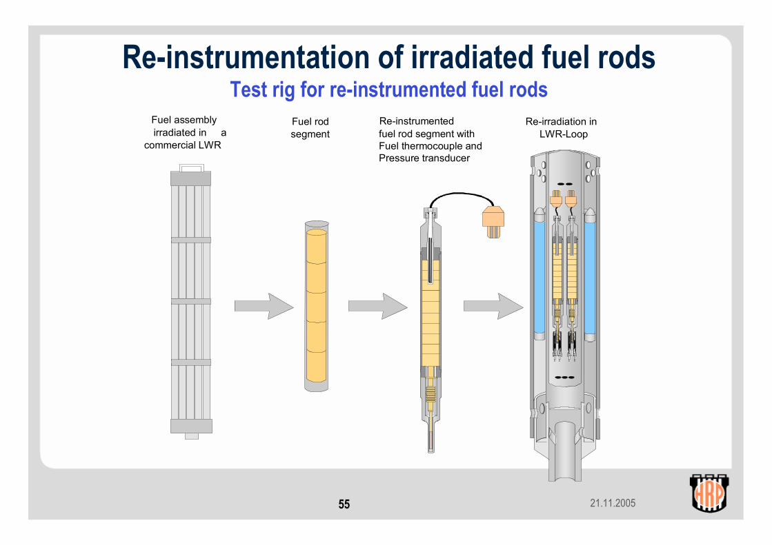
Re-instrumentation of irradiated fuel rods Test rig for re-instrumented fuel rods
Fuel assemblyirradiated in a
commercial LWR
Fuel rodsegment
Re-instrumentedfuel rod segment withFuel thermocouple andPressure transducer
Re-irradiation inLWR-Loop
21.11.200556
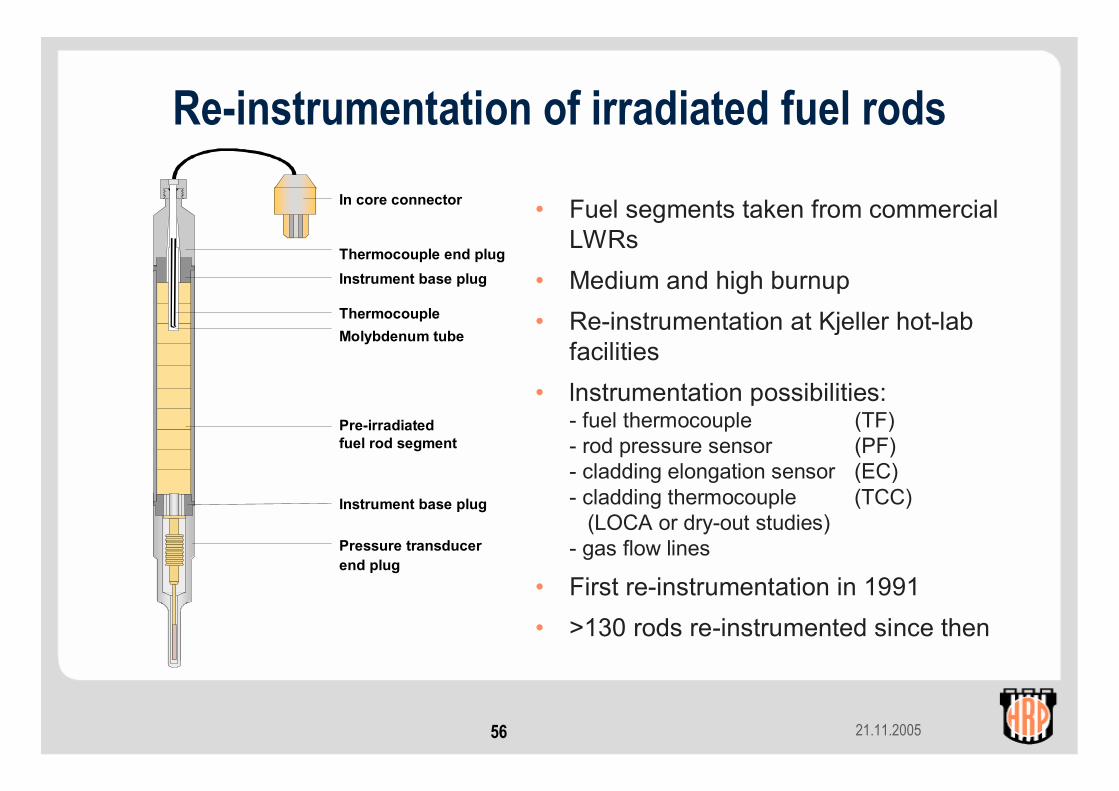
In core connector
Thermocouple end plugInstrument base plug
Pre-irradiatedfuel rod segment
Instrument base plug
Pressure transducerend plug
ThermocoupleMolybdenum tube
• Fuel segments taken from commercial LWRs
• Medium and high burnup• Re-instrumentation at Kjeller hot-lab
facilities• lnstrumentation possibilities:
- fuel thermocouple (TF)- rod pressure sensor (PF)- cladding elongation sensor (EC)- cladding thermocouple (TCC)
(LOCA or dry-out studies)- gas flow lines
• First re-instrumentation in 1991• >130 rods re-instrumented since then
Re-instrumentation of irradiated fuel rods
21.11.200557
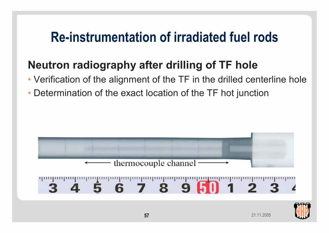
Re-instrumentation of irradiated fuel rods
Neutron radiography after drilling of TF hole• Verification of the alignment of the TF in the drilled centerline hole• Determination of the exact location of the TF hot junction
21.11.200558
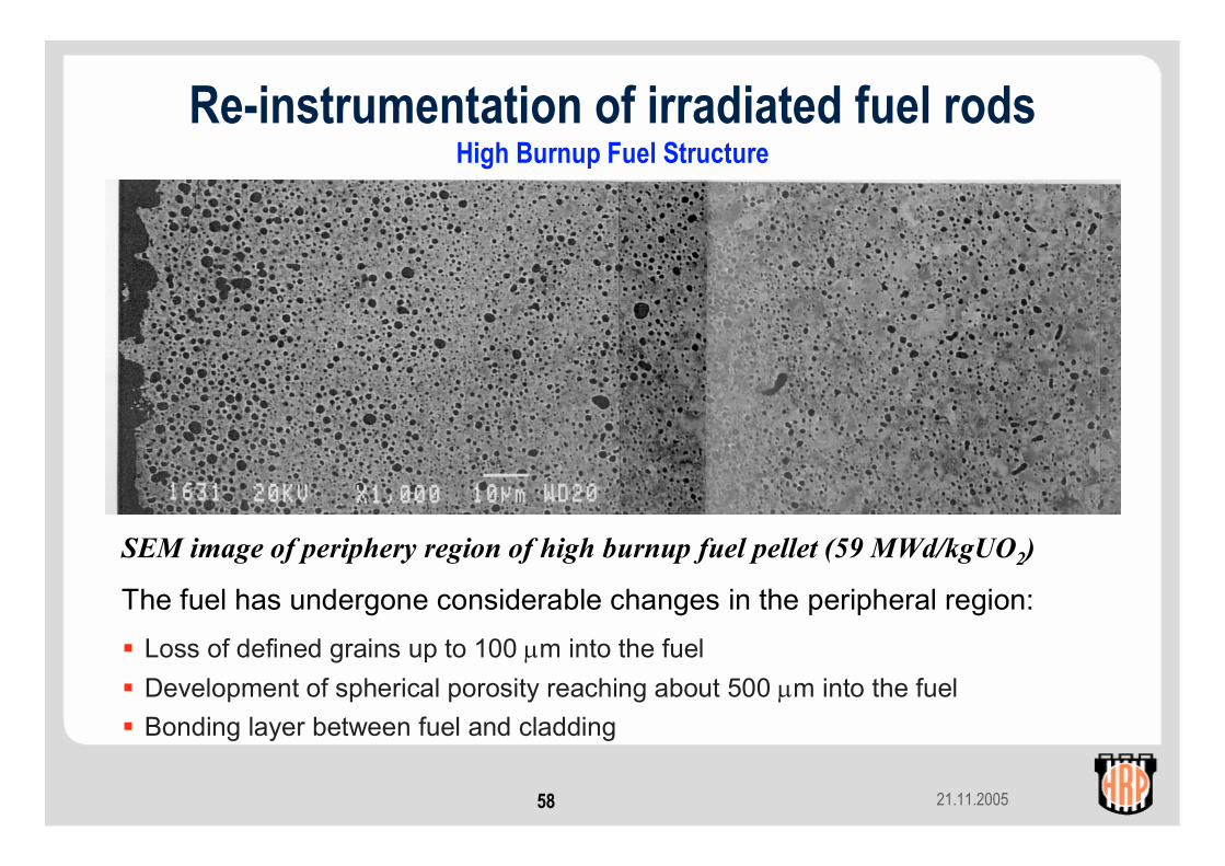
Loss of defined grains up to 100 µm into the fuelDevelopment of spherical porosity reaching about 500 µm into the fuelBonding layer between fuel and cladding
SEM image of periphery region of high burnup fuel pellet (59 MWd/kgUO2)
The fuel has undergone considerable changes in the peripheral region:
Re-instrumentation of irradiated fuel rodsHigh Burnup Fuel Structure
21.11.200559
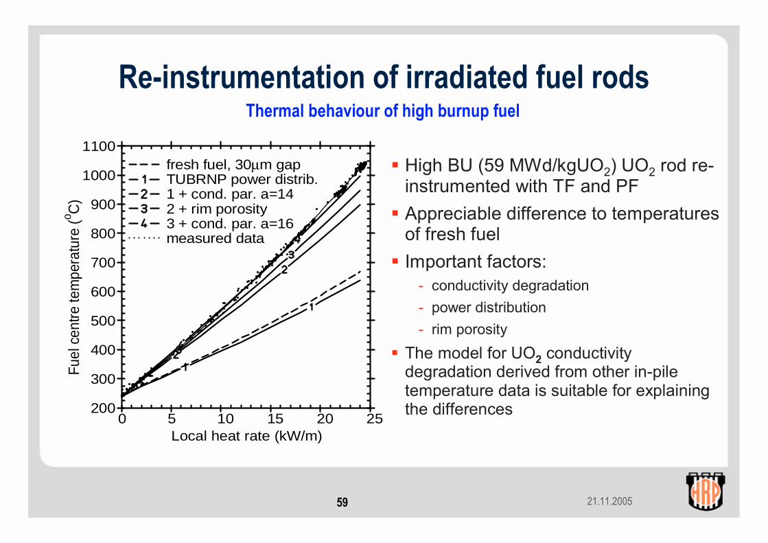
Thermal behaviour of high burnup fuel
High BU (59 MWd/kgUO2) UO2 rod re-instrumented with TF and PFAppreciable difference to temperatures of fresh fuelImportant factors:
- conductivity degradation- power distribution- rim porosity
The model for UO2 conductivity degradation derived from other in-pile temperature data is suitable for explaining the differences
0 5 10 15 20 25200
300
400
500
600
700
800
900
1000
1100
Local heat rate (kW/m)
Fuel
cen
tre te
mpe
ratu
re (o C
)
fresh fuel, 30µm gap TUBRNP power distrib. 1 + cond. par. a=14 2 + rim porosity 3 + cond. par. a=16 measured data
Re-instrumentation of irradiated fuel rods

21.11.200560
Gap conductance, high burnup fuel
Experimental rigs with gas lines provide for a change of fill gas during in-core service. This feature allows to assess the dependence of gap conductance on fill gas composition. For high burnup fuel, the temperature response to fill gas change (Ar < > He) is small.
A similar behaviour is seen when a burst release of fission gas occurs during a power decrease. This is the consequence of the tightly closed fuel - clad gap.
0 2 4 6 8 10 12 14 16 18300
400
500
600
700
800
Local Heat Rate (kW/m)
Fuel
Tem
pera
ture
(o C)
Helium
Argon
Temperature response to fill gas change (He <> Ar), IFA-610
Re-instrumentation of irradiated fuel rods

21.11.200561
Re-instrumented PWR fuel: PCMI: Initial
• PWR UO2 fuel (52 MWd/kgUO2)
• Re-instrumented with EC• No appreciable PCMI for the
first ramp since the conditioning power of 20 kW/m is not exceeded
• Linear elongation part is more than calculated for thermal expansion
• Some re-conditioning during 2.5 MWd/kg burnup increment between second and last ramp
21.11.200562
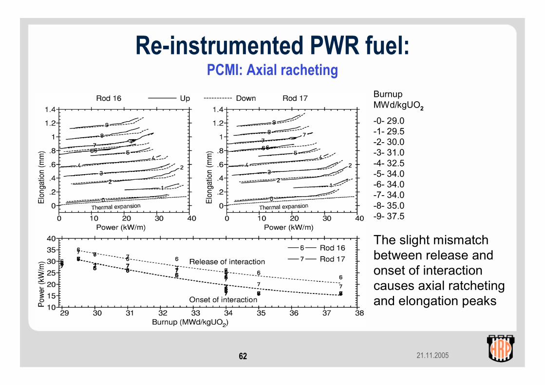
Re-instrumented PWR fuel: PCMI: Axial racheting
BurnupMWd/kgUO2
-0- 29.0-1- 29.5-2- 30.0-3- 31.0-4- 32.5-5- 34.0-6- 34.0-7- 34.0-8- 35.0-9- 37.5
The slight mismatch between release and onset of interaction causes axial ratcheting and elongation peaks
21.11.200563
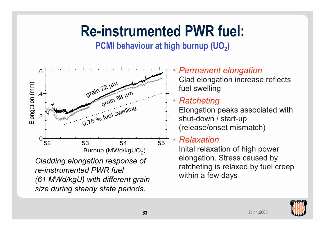
Re-instrumented PWR fuel:PCMI behaviour at high burnup (UO2)
• Permanent elongationClad elongation increase reflects fuel swelling
• RatchetingElongation peaks associated with shut-down / start-up(release/onset mismatch)
• RelaxationInital relaxation of high powerelongation. Stress caused by ratcheting is relaxed by fuel creep within a few days
Cladding elongation response ofre-instrumented PWR fuel(61 MWd/kgU) with different grain size during steady state periods.
52 53 54 550
.2
.4
.6
Elo
ngat
ion
(mm
)
Burnup (MWd/kgUO2)
grain 38 µm grain 22 µm
0.75 % fuel swelling

21.11.200564
• PWR MOX rod (~46 MWd/kgOxide)
• Re-instrumented: TF + EC• Permanent elongation
Clad elongation increase reflects fuel swelling
• RelaxationStronger relaxation than for UO2fuel at similar burnup
• Increased fuel creep?
Re-instrumented PWR fuel:PCMI behaviour at high burnup (MOX)
21.11.200565
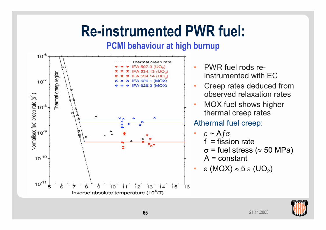
Re-instrumented PWR fuel:PCMI behaviour at high burnup
• PWR fuel rods re-instrumented with EC
• Creep rates deduced from observed relaxation rates
• MOX fuel shows higher thermal creep rates
Athermal fuel creep:• ε ~ Aƒσ
f = fission rateσ = fuel stress (≈ 50 MPa)A = constant
• ε (MOX) ≈ 5 ε (UO2)

21.11.200566
• PWR UO2 rod re-instrumetedwith TF, EC and gas line
• Rod overpressure(>130 bar above system pressure) causes clad lift-off and a measurable temperature increase
• Clad lift-off causes the hydraulic diameter to increase.
• Noise analysis (power –elongation) indicates continued contact between fuel and cladding
0 5 10 15 2010
15
20
25
30
35
40
rod power, kW/m hydr
aulic
dia
met
er, µ
m
before pressurisation
after 2300 fph
0 800 1600 2400650
675
700
725
750
.3
.4
.5
.6
.7
.8
.9
1
full power hours fuel
tem
pera
ture
, o C
cohe
renc
e N
D -
EC
ooo
xxx
Hilary Kolstad 25ppt
Re-instrumented PWR fuel:PCMI and rod overpressure – noise analysis
21.11.200567
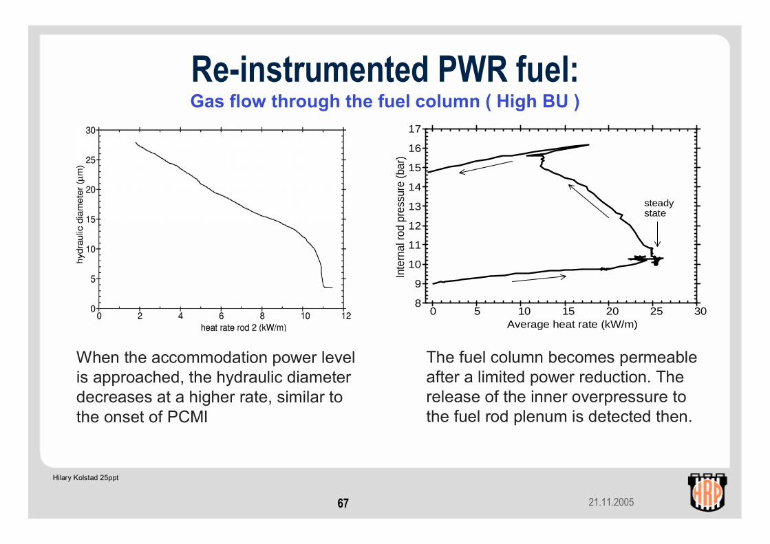
The fuel column becomes permeable after a limited power reduction. The release of the inner overpressure to the fuel rod plenum is detected then.
When the accommodation power level is approached, the hydraulic diameter decreases at a higher rate, similar to the onset of PCMI
0 5 10 15 20 25 308
9
10
11
12
13
14
15
16
17
Average heat rate (kW/m)
Inte
rnal
rod
pres
sure
(bar
)
steadystate
Hilary Kolstad 25ppt
Re-instrumented PWR fuel:Gas flow through the fuel column ( High BU )

21.11.200568
• PWR MOX rod (~46 MWd/kgOxide)
• Re-instrumented: TF + PF• Stepwise power / temperature
increase to establish onset of fission gas release
• For high burnup fuel, power dips are necessary in order to obtain communication with the plenum and PF instrument (tight fuel column)
• Envelope of release curve indicates diffusion controlled releaseTemperature and FGR history
Re-instrumented PWR fuel:Fission gas release onset
21.11.200569
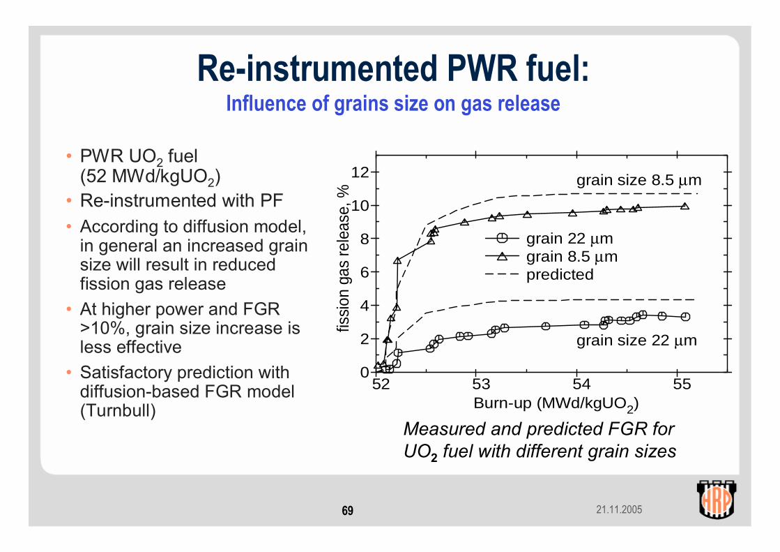
Re-instrumented PWR fuel: Influence of grains size on gas release
• PWR UO2 fuel (52 MWd/kgUO2)
• Re-instrumented with PF• According to diffusion model,
in general an increased grain size will result in reduced fission gas release
• At higher power and FGR>10%, grain size increase is less effective
• Satisfactory prediction with diffusion-based FGR model (Turnbull)
Measured and predicted FGR for UO2 fuel with different grain sizes
52 53 54 550
2
4
6
8
10
12
Burn-up (MWd/kgUO2)
fissi
on g
as re
leas
e, %
grain size 22 µm
grain size 8.5 µm
grain 22 µm grain 8.5 µm predicted
21.11.200570
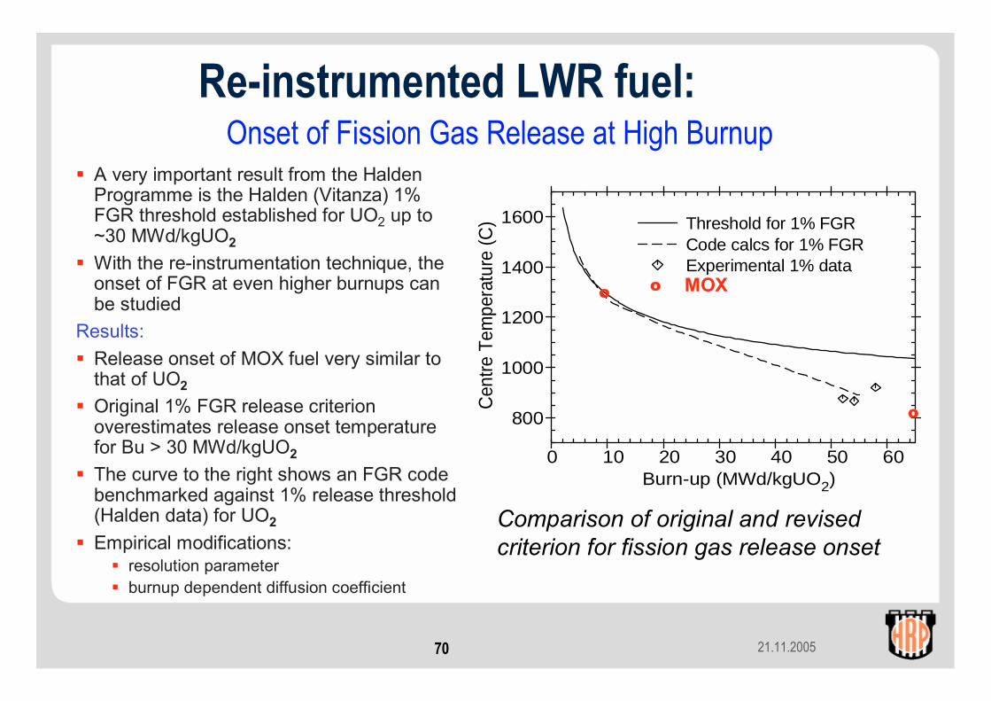
Onset of Fission Gas Release at High BurnupA very important result from the Halden Programme is the Halden (Vitanza) 1% FGR threshold established for UO2 up to ~30 MWd/kgUO2With the re-instrumentation technique, the onset of FGR at even higher burnups can be studied
Results:Release onset of MOX fuel very similar to that of UO2Original 1% FGR release criterion overestimates release onset temperature for Bu > 30 MWd/kgUO2The curve to the right shows an FGR code benchmarked against 1% release threshold (Halden data) for UO2
Empirical modifications:resolution parameterburnup dependent diffusion coefficient
Comparison of original and revised criterion for fission gas release onset
Re-instrumented LWR fuel:
0 10 20 30 40 50 60
800
1000
1200
1400
1600
Burn-up (MWd/kgUO2) C
entre
Tem
pera
ture
(C) Threshold for 1% FGR
Code calcs for 1% FGR Experimental 1% data
o
o MOXo
21.11.200571
Contents (contd.)3. Materials testing
a. LWR loop systemsb. Crack growth measurements with potential drop techniquec. Crack initiationd. Clad diameter measurements
• Cladding creep• PWR CRUD
e. Stress relaxation
21.11.200572
LWR loops• Allow testing of fuel clad and materials under simulated
BWR, PWR or CANDU conditions:• Coolant pressure• Coolant temperature• Water chemistry
21.11.200573
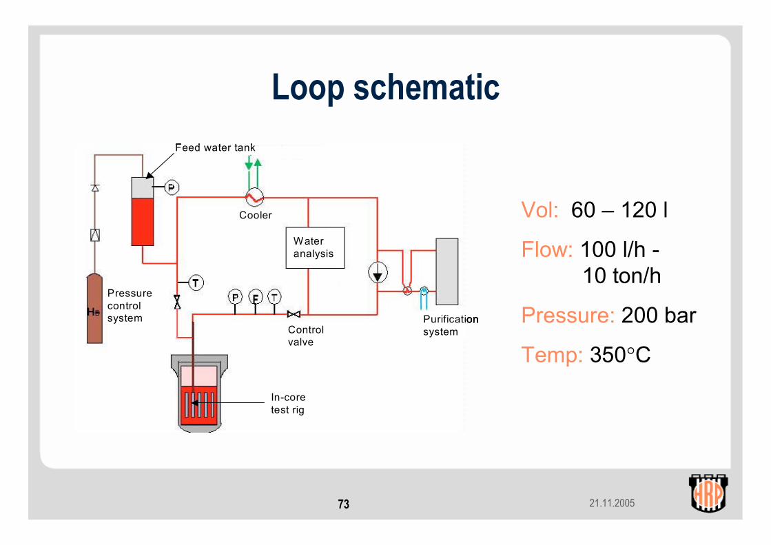
Loop schematic
Cooler
Wateranalysis
Purificationsystem
Pressurecontrolsystem
Controlvalve
In-coretest rig
Feed water tank
Cooler
Wateranalysis
Purificationsystem
Pressurecontrolsystem
Controlvalve
In-coretest rig
Feed water tank
Cooler
Wateranalysis
Purificationsystem
Pressurecontrolsystem
Controlvalve
In-coretest rig
Cooler
Wateranalysis
Purificationsystem
Pressurecontrolsystem
Controlvalve
In-coretest rig
Feed water tank
Vol: 60 – 120 l
Flow: 100 l/h -10 ton/h
Pressure: 200 bar
Temp: 350°C
21.11.200574
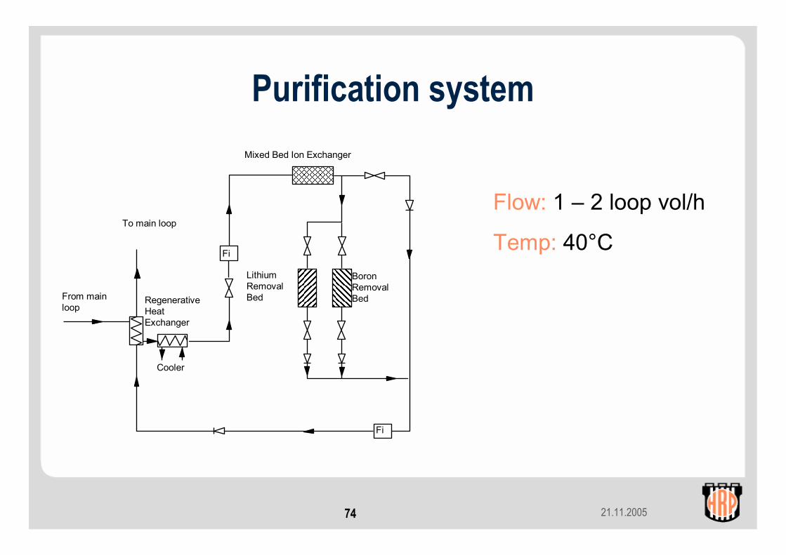
Purification systemMixed Bed Ion Exchanger
Cooler
LithiumRemovalBedRegenerative
HeatExchanger
BoronRemovalBed
Fi
Fi
From main loop
To main loop
Flow: 1 – 2 loop vol/h
Temp: 40°C
21.11.200575
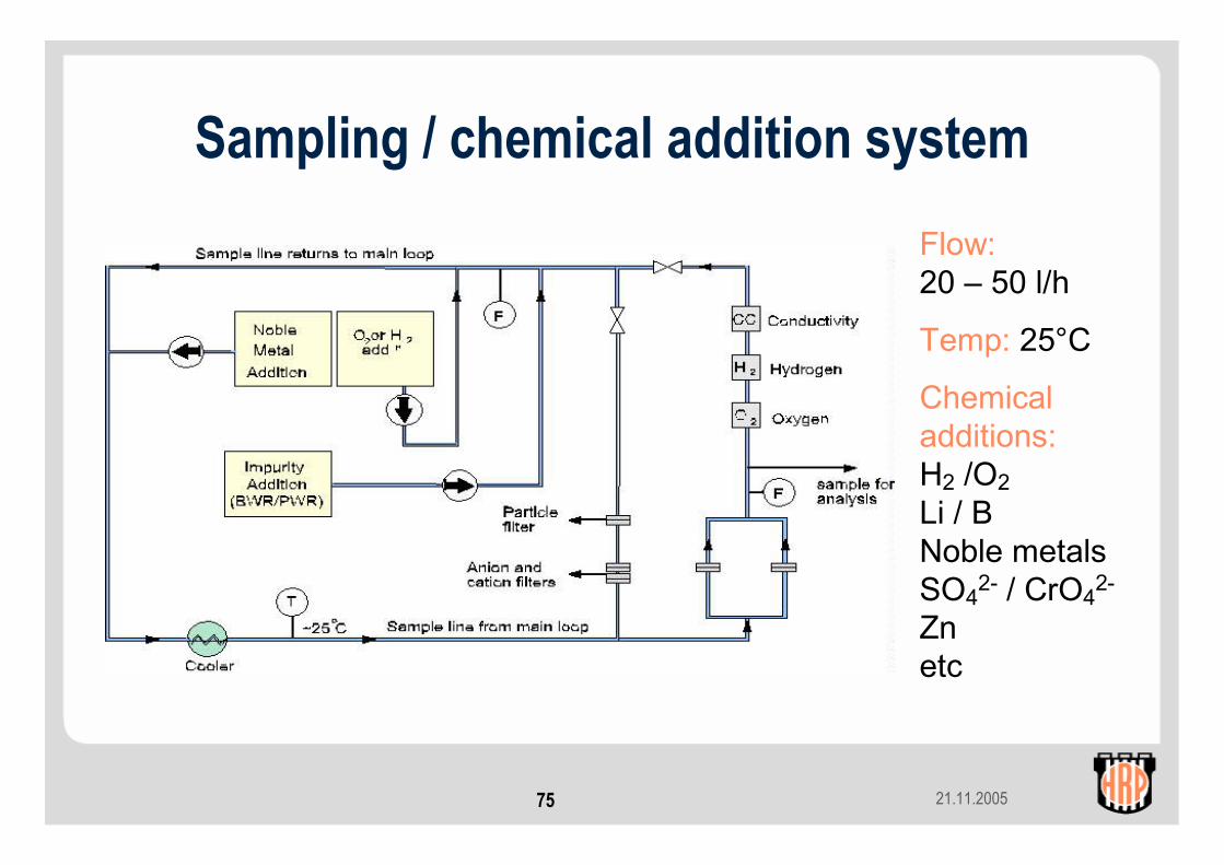
Sampling / chemical addition systemFlow:20 – 50 l/h
Temp: 25°C
Chemical additions:H2 /O2Li / BNoble metalsSO4
2- / CrO42-
Znetc

21.11.200576
Water analyses – grab samples
• Atomic absorption spectrometry (Li)• Mannitol titration (B)• ICP-MS (dissolved transition metals)• Capillary Electrophoresis (dissolved anions)• pH, total organic caron (TOC)
21.11.200577
Water analyses – filter samples(integrated sampling)
• Coolant passed through filter packs (particle filters and ion exchange membranes) for approx 3 hours
• X-ray flourescence spectrometry (soluble and insoluble corrosion products)
• Gamma spectrometry (soluble and insoluble active nuclides – Co-58, Co-60, Fe-59, Mn-54, Cr-51 etc)
21.11.200578
Typical conditions – BWR loops
• Coolant pressure 75 bar• Inlet water temperature 270 – 288°C• Addition of H2 or O2 to simulate HWC or NWC• (eg) SO4 2- addition for conductivity control• In-core: suppressed boiling or boiling along a specific
section of fuel rods

21.11.200579
Typical conditions – PWR loops
• Coolant pressure 155 - 165 bar• Inlet water temperature 290 – 320°C• Sub-cooled nucleate boiling control• Addition of 2 – 5 ppm H2
• Addition of LiOH, boric acid (pH control)
21.11.200580
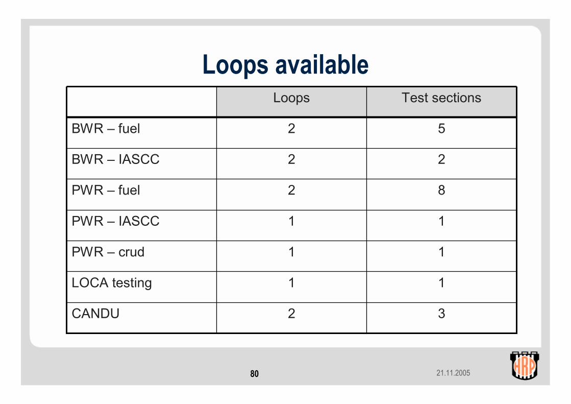
Loops available
32CANDU
11LOCA testing
11PWR – crud
11PWR – IASCC
82PWR – fuel
22BWR – IASCC
52BWR – fuel
Test sectionsLoops
21.11.200581
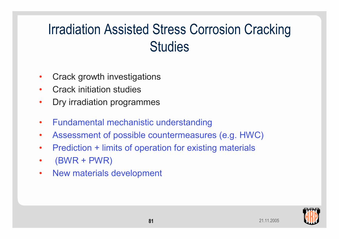
Irradiation Assisted Stress Corrosion Cracking Studies
• Crack growth investigations• Crack initiation studies• Dry irradiation programmes
• Fundamental mechanistic understanding• Assessment of possible countermeasures (e.g. HWC) • Prediction + limits of operation for existing materials • (BWR + PWR) • New materials development
21.11.200582
Core Structural Component Material StudiesCrack Growth Tests
• Early studies aimed at developing suitable specimen geometries, instrumentation for monitoring crack growth + loading methods enabling on-line variation of applied stress levels
• Current investigations focus on generating crack growth rate data for irradiated materials retrieved from commercial plants
21.11.200583
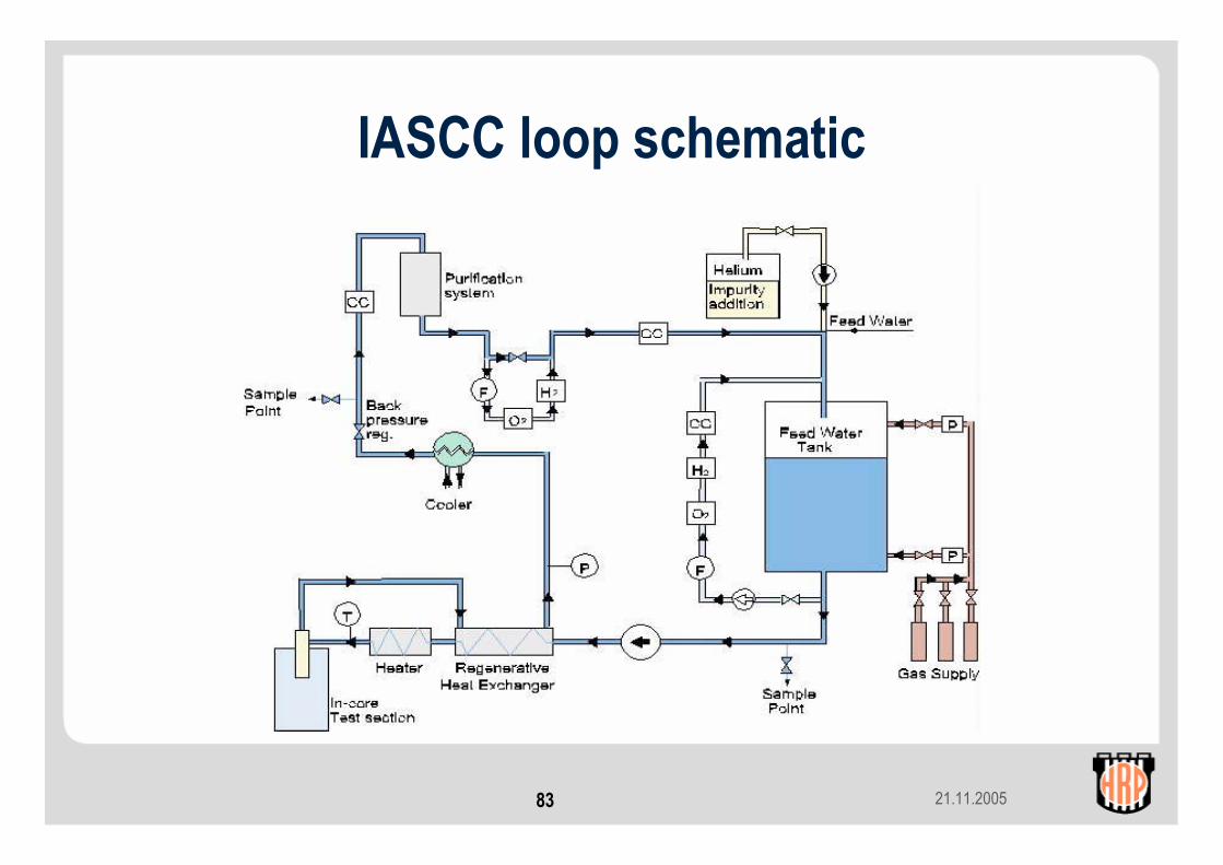
IASCC loop schematic
21.11.200584
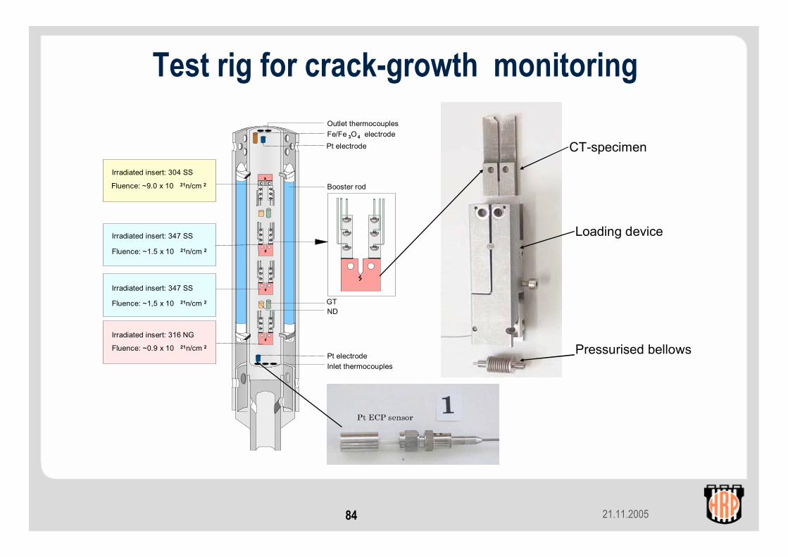
Inlet thermocouples
Outlet thermocouplesFe/Fe 3O4 electrode
NDGT
Pt electrode
Booster rod
Irradiated insert: 304 SS
Fluence: ~9.0 x 10 21n/cm 2
Irradiated insert: 347 SS
Fluence: ~1.5 x 10 21n/cm 2
Irradiated insert: 316 NG
Fluence: ~0.9 x 10 21n/cm 2
Pt electrode
Irradiated insert: 347 SS
Fluence: ~1,5 x 10 21n/cm 2
Test rig for crack-growth monitoring
CT-specimen
Loading device
Pressurised bellows
21.11.200585
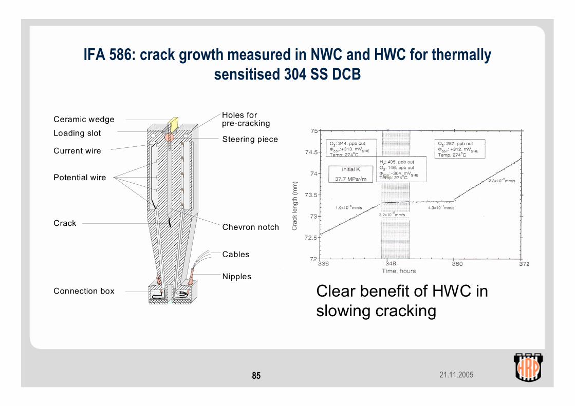
IFA 586: crack growth measured in NWC and HWC for thermally sensitised 304 SS DCB
Ceramic wedge
Loading slot
Holes forpre-cracking
Crack
Steering pieceCurrent wire
Potential wire
Connection box
Chevron notch
Cables
Nipples
Clear benefit of HWC in slowing cracking
21.11.200586
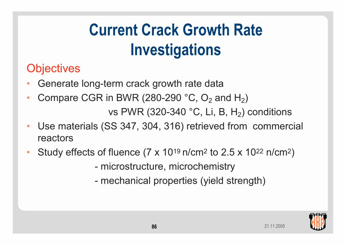
Objectives• Generate long-term crack growth rate data• Compare CGR in BWR (280-290 °C, O2 and H2)
vs PWR (320-340 °C, Li, B, H2) conditions• Use materials (SS 347, 304, 316) retrieved from commercial
reactors • Study effects of fluence (7 x 10¹⁹ n/cm2 to 2.5 x 10²² n/cm2)
- microstructure, microchemistry- mechanical properties (yield strength)
Current Crack Growth Rate Investigations
21.11.200587
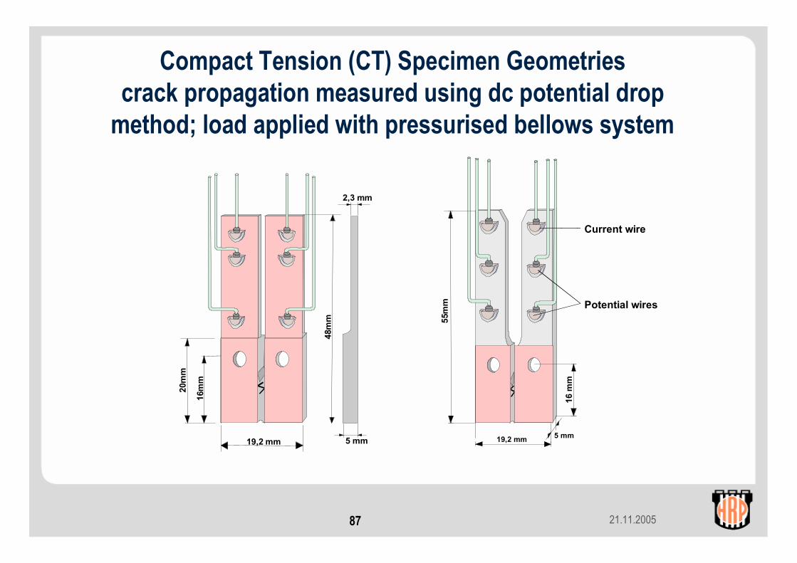
Compact Tension (CT) Specimen Geometriescrack propagation measured using dc potential drop
method; load applied with pressurised bellows system
19,2 mm
16 m
m
19,2 mm 5 mm55
mm
Current wire
Potential wires
48m
m
2,3 mm
5 mm
16m
m
20m
m
21.11.200588
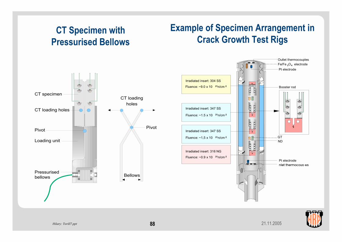
CT specimen
CT loading holes
Pivot
Loading unit
Pressurised bellows
Hilary: Torill7.ppt
Outlet thermocouplesFe/Fe 3O4 electrode
NDGT
Pt electrode
Booster rod
Irradiated insert: 304 SS
Fluence: ~9.0 x 10 21n/cm 2
Irradiated insert: 347 SS
Fluence: ~1.5 x 10 21n/cm 2
Irradiated insert: 316 NG
Fluence: ~0.9 x 10 21n/cm 2
Pt electrode
Irradiated insert: 347 SS
Fluence: ~1,5 x 10 21n/cm 2
CT loading
holes
Pivot
Bellows
CT Specimen with Pressurised Bellows
Example of Specimen Arrangement in Crack Growth Test Rigs
21.11.200589
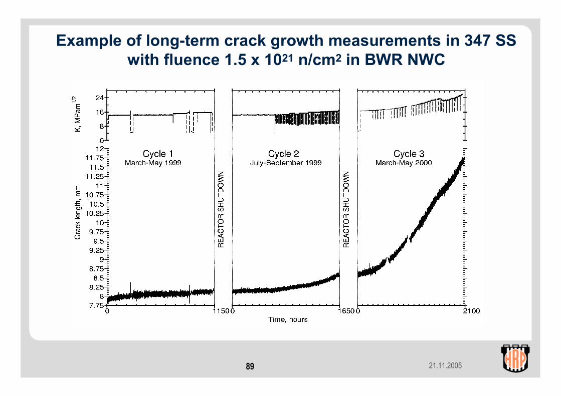
Example of long-term crack growth measurements in 347 SS with fluence 1.5 x 10²¹ n/cm2 in BWR NWC

21.11.200590
Lower fluence material – beneficial effect of BWR HWC
21.11.200591
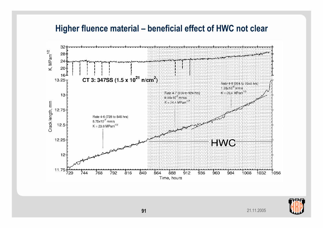
Higher fluence material – beneficial effect of HWC not clear

21.11.200592
Example of crack growth rates measured for CT in PWR Conditions
21.11.200593
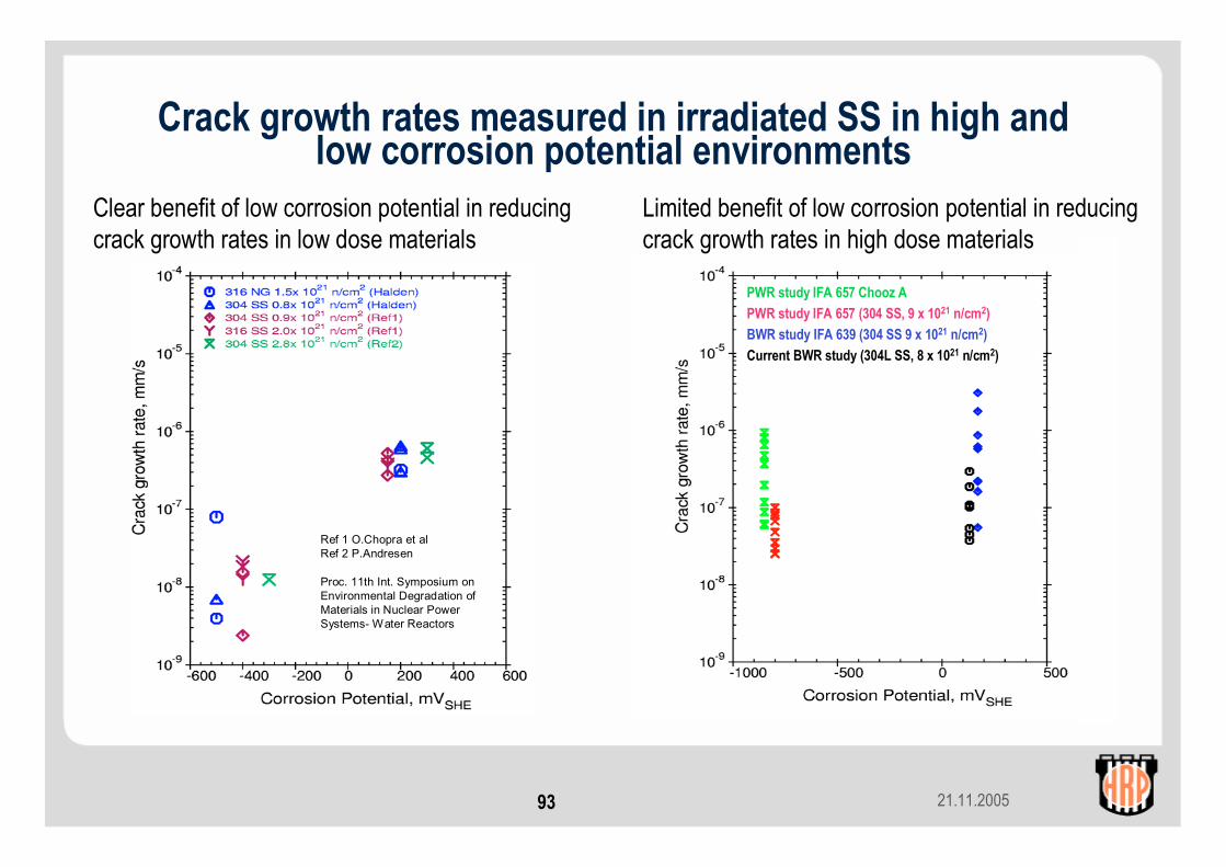
Crack growth rates measured in irradiated SS in high and low corrosion potential environments
PWR study IFA 657 Chooz APWR study IFA 657 (304 SS, 9 x 10²¹ n/cm2)BWR study IFA 639 (304 SS 9 x 10²¹ n/cm2)Current BWR study (304L SS, 8 x 10²¹ n/cm2)
Clear benefit of low corrosion potential in reducing crack growth rates in low dose materials
Limited benefit of low corrosion potential in reducing crack growth rates in high dose materials
Ref 1 O.Chopra et alRef 2 P.Andresen
Proc. 11th Int. Symposium on Environmental Degradation of Materials in Nuclear Power Systems- Water Reactors

21.11.200594
CGR vs yield strength(cold worked and irradiated materials)
Higher CGRs in irradiated material:
RIS + increased YS
IFA-639 crack growth rates normalised:
CGRcalc
=CGRmeas*(27/Kmeas)2
21.11.200595
Crack initiation studies
• Use of pressurised tubes to study• effects of material, stress + fluence on crack initiation
• Use of tensile specimens for integrated time-to-failure (crack initiation, propagation, final failure) tests • effects of water chemistry on susceptibility to crack initiation
• Both investigations with on-line instrumentation (LVDTs)
21.11.200596
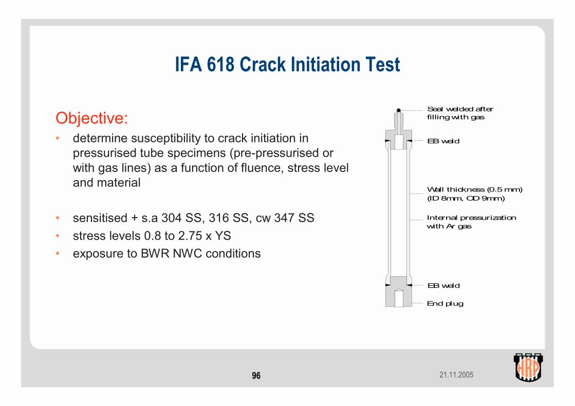
IFA 618 Crack Initiation Test
Objective:• determine susceptibility to crack initiation in
pressurised tube specimens (pre-pressurised or with gas lines) as a function of fluence, stress level and material
• sensitised + s.a 304 SS, 316 SS, cw 347 SS• stress levels 0.8 to 2.75 x YS• exposure to BWR NWC conditions
Internal pressurizationwith Ar gas
EB weld
End plug
Wall thickness (0.5 mm)(ID 8mm, OD 9mm)
EB weld
Seal welded afterfilling with gas
21.11.200597
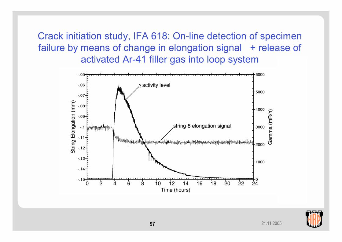
Crack initiation study, IFA 618: On-line detection of specimen failure by means of change in elongation signal + release of
activated Ar-41 filler gas into loop system

21.11.200598
Objective• Determine effectiveness of HWC in reducing susceptibility to the
initiation of cracks in irradiated material
Experimental• 30 miniature tensile specimens prepared from 304L SS
(8x10²¹ n/cm2, YS 718 MPa)• Load (77- 86 % of YS) applied by means of bellows• On-line monitoring of specimen failures (LVDTs)
BWR Crack Initiation (Integrated Time-to-Failure) Study IFA-660
21.11.200599
Experimental contd
1st loading:Expose 30 specimens to ”NWC” (5 ppm O2) for several cycles; record no. of failures2nd loading:Expose replacement set of specimens to ”HWC” (2 ppm H2) for
several cycles; record no. of failures
Comparison → effectiveness of HWC
BWR Crack Initiation (Integrated Time-to-Failure) Study IFA-660
21.11.2005100
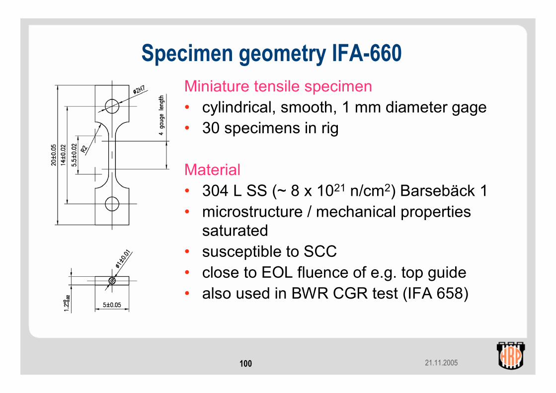
Miniature tensile specimen• cylindrical, smooth, 1 mm diameter gage• 30 specimens in rig
Material• 304 L SS (~ 8 x 10²¹ n/cm2) Barsebäck 1 • microstructure / mechanical properties
saturated• susceptible to SCC• close to EOL fluence of e.g. top guide• also used in BWR CGR test (IFA 658)
Specimen geometry IFA-660
21.11.2005101
LVDT
1. Always fixed
2. Always fixed
3. Moves up if upper specimen fails
4. Moves up if upper specimen fails
Step A
Both specimens intact
Step B
Upper specimen breaks
Step C
Lower specimen breaks
4. Moves up if lower specimen fails
Magnetic core
LVDT
1. Always fixed
2. Always fixed
3. Moves up if upper specimen fails
4. Moves up if upper specimen fails
Step A
Both specimens intact
Step B
Upper specimen breaks
Step C
Lower specimen breaks
4. Moves up if lower specimen fails
Magnetic core
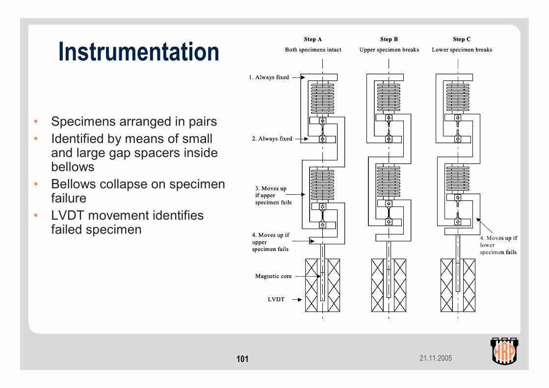
• Specimens arranged in pairs• Identified by means of small
and large gap spacers inside bellows
• Bellows collapse on specimen failure
• LVDT movement identifies failed specimen
Instrumentation
21.11.2005102
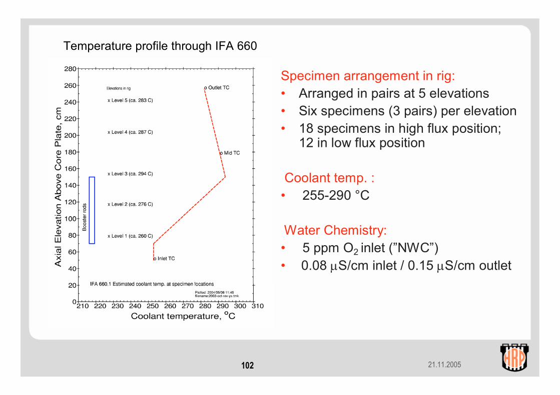
Temperature profile through IFA 660
Specimen arrangement in rig:• Arranged in pairs at 5 elevations• Six specimens (3 pairs) per elevation• 18 specimens in high flux position;
12 in low flux position
Coolant temp. :• 255-290 °C
Water Chemistry:• 5 ppm O2 inlet (”NWC”)• 0.08 µS/cm inlet / 0.15 µS/cm outlet
21.11.2005103
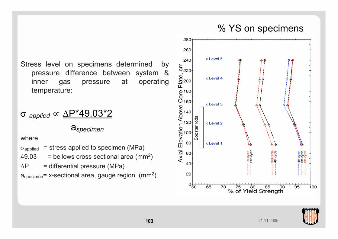
Stress level on specimens determined by pressure difference between system & inner gas pressure at operating temperature:
σ applied ∝ ∆P*49.03*2aspecimen
whereσapplied = stress applied to specimen (MPa)49.03 = bellows cross sectional area (mm2)∆P = differential pressure (MPa)aspecimen= x-sectional area, gauge region (mm2)
% YS on specimens

21.11.2005104
Example of Specimen Failure (Specimen No. 24 from Unit 12)(failed at 6070 fph (> 2MW), ~50 hrs after stress level increased from ~77 to 83
% YS)
Change in LVDT signal as specimen fails
21.11.2005105
Diameter Gauge (DG)b a a b c
e
gf
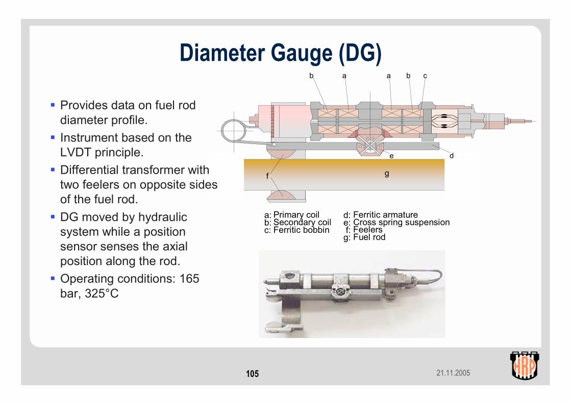
Primary coilSecondary coilFerritic bobbin
Ferritic armatureCross spring suspensionFeelersFuel rod
a:b:c:
d:e:f:g:
d
Provides data on fuel rod diameter profile.Instrument based on the LVDT principle.Differential transformer with two feelers on opposite sides of the fuel rod.DG moved by hydraulic system while a position sensor senses the axial position along the rod.Operating conditions: 165 bar, 325°C

21.11.2005106
Creep and growth of Zr-based materials
Provide engineering data on creep and growth of zirconium alloys caused by various operating conditions:
clad creep-down (compressive, BOL)
clad creep-out (tensile, MOL to EOL)
guide tube creep and growth (bilateral)(axially compressive)
In-core diameter measurements provide direct data on primary and secondary creep behaviour.

21.11.2005107
Cladding Creep Test Rig Design• Pressure flask with high enrichment
booster fuel connected to a PWR loop
• 2 internally gas pressurised closed-end cladding tubes
• 4 segments in-flux: VVER, ZIRLO, M5 and BWR (GE)
• 1 seg. out-of-flux BWR (GE)• 2 scanning contact diameter gauges
for OD changesPressure flaskcoolant valve
Outer shroud
Hydraulic drive unit+ position indicator
Diameter gauge
Thermal shield
Outer ring of booster rods(12 rods, D O2 forced circulation)
Outer shroud
Thermal shield
Steam annulus
Pressure flask
Gas line for pressure control
Outlet thermocouples
Inletthermocouples
Pressure flask
Diameter gauge
Neutron detector
Neutron detector
21.11.2005108
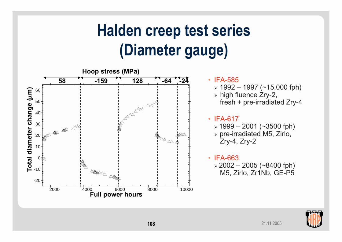
Halden creep test series(Diameter gauge)
2000 4000 6000 8000 10000
-20
-10
0
10
20
30
40
50
60
Tota
l dia
met
er c
hang
e(µ
m)
Full power hours
Hoop stress (MPa)58 -159 128 -64 -24 • IFA-585
1992 – 1997 (~15,000 fph)high fluence Zry-2, fresh + pre-irradiated Zry-4
• IFA-6171999 – 2001 (~3500 fph)pre-irradiated M5, Zirlo,Zry-4, Zry-2
• IFA-6632002 – 2005 (~8400 fph) M5, Zirlo, Zr1Nb, GE-P5
21.11.2005109
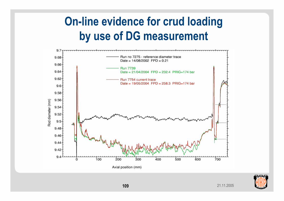
On-line evidence for crud loading by use of DG measurement
21.11.2005110
Stress Relaxation Test IFA-669Objectives• Establish the technical feasibility of on-line stress
relaxation measurements during irradiation
• Measure the irradiation stress relaxation of materials used in PWR and BWR plants
• Benchmark irradiation stress relaxation data to irradiation creep data
• Evaluate the applicability of the Halden stress relaxation data to other reactors (EBR II + commercial PWRs)
21.11.2005111
Specimens• 30 tensile specimens (~2.5 mm, gauge length ~50 mm)
12 samples in instrumented units18 samples in uninstrumented units
Materials• CW 316, CW 316LN, CW 316N, SA 304 SS; Aged Alloy 718
Test Conditions• Stress Levels 70-345 MPa • Temperatures 290, 330 and 370 °C• Fluences 0.4, 1.6 + 2.0 dpa
Irradiation Arrangement• Irradiation in inert (dry) irradiation conditions• Maximum dose level 2 dpa (~1.4 x 10²¹ n/cm2)
Stress Relaxation Test IFA-669

21.11.2005112
12 instrumented specimens
Tensile specimen
Filler body (removed for visibility of specimen)
Load pin
Gas gap for temperature control
Outlet gas-line
Thermocouple
bellows loading device
Pressure line
Linear voltage differential transformer (LVDT)
Inlet gas-line
Inner capsule
Outer capsule
Signal cables
Tensile specimen
Filler body (removed for visibility of specimen)
Load pin
Gas gap for temperature control
Outlet gas-line
Thermocouple
bellows loading device
Pressure line
Linear voltage differential transformer (LVDT)
Inlet gas-line
Inner capsule
Outer capsule
Signal cables
• gas lines for on-line temperature control alter He-Ar gas mixture• LVDTs monitor sample elongation• stress applied with bellows• constant displacement maintained by reducingapplied stress on-line by bellows pressure• 2 instrumented samples operated in “creep-mode”(stress constant + displacement measured continuously)

21.11.2005113
Test Matrix Instrumented Specimens IFA-669Material No. Temp. Stress Dose Comment
(°C) (MPa) (dpa)
CW 316 1 +2* 330 345 2.0 Replacement baffle bolt + split pin matl
CW 316 1 330 275 2.0 * 2 specimens operated in creep mode
CW 316 1 330 205 2.0CW 316 1 330 ---- 2.0 Qualification sample
CW 316 LN 1 330 345 2.0 Low irradiation creep matl
CW 316 N lot 1 370 345 2.0 EBR II irradiation creep test archive
SA 304 L 1 290 90 2.0 EBR II irradiation creep test archive
SA 304 L 1 290 72 2.0
Alloy 718 2 330 345 2.0 PWR irradiation stress relaxation data

21.11.2005114
Test Matrix, Uninstrumented Specimens IFA-669
Material No. Temp. Stress Dose Comment(°C) (MPa) (dpa)
CW 316 2 330 275 0.4 Second phase ppt densification data
CW 316 2 330 275 1.6CW 316 2 330 275 2.0
SA 304 2 290 90 0.4 Baffle former plate material
SA 304 2 290 90 1.6SA 304 2 290 90 2.0
Alloy 718 2 330 345 0.4 Second phase ppt densification data
Alloy 718 2 330 345 1.6Alloy 718 2 330 345 2.0
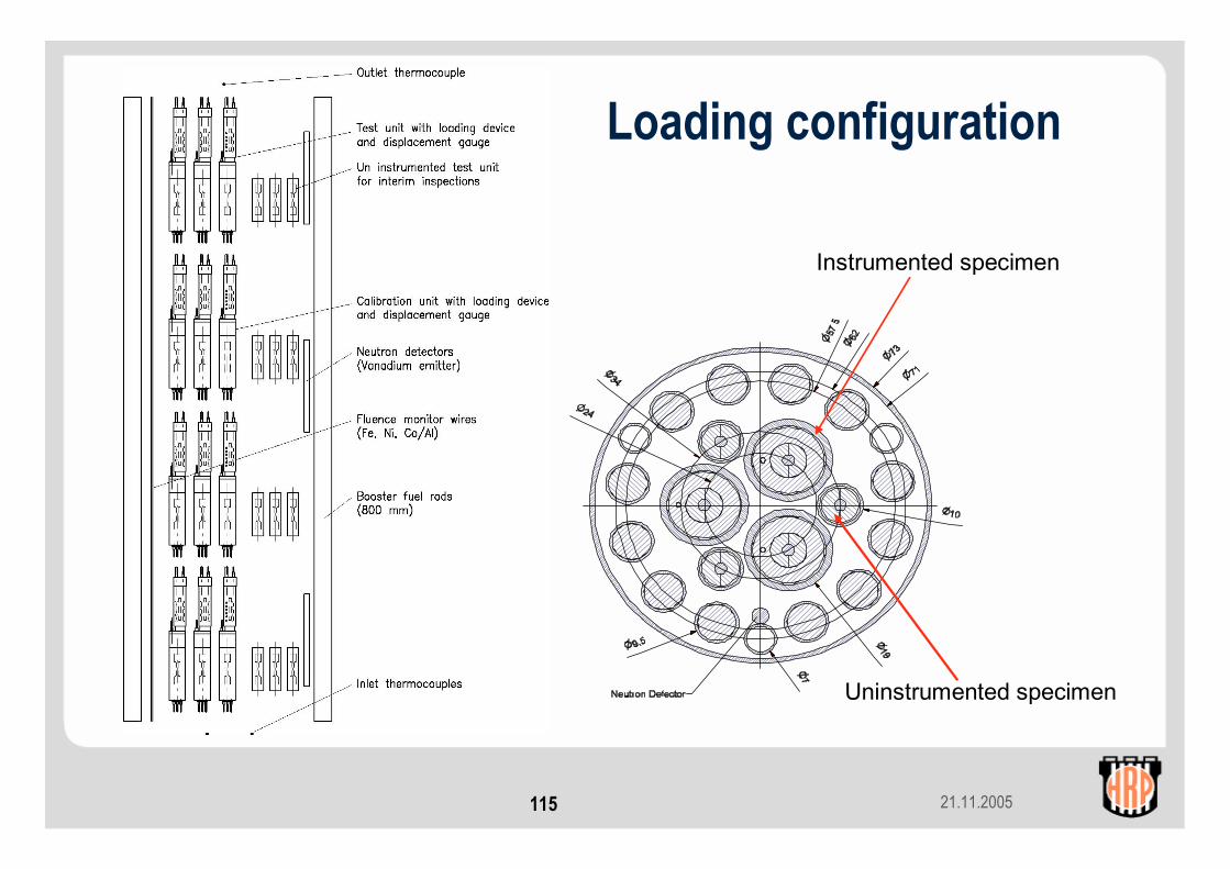
21.11.2005115
Loading configuration
Instrumented specimen
Uninstrumented specimen
21.11.2005116
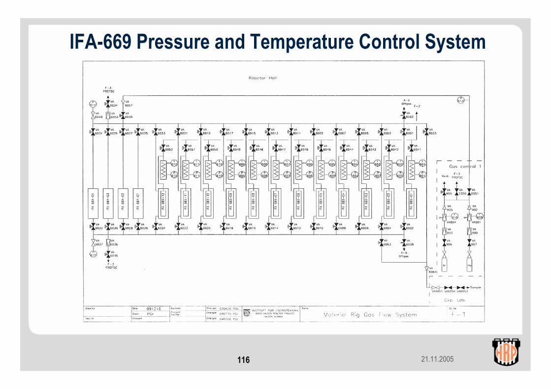
IFA-669 Pressure and Temperature Control System
21.11.2005117
Contents (contd.)
4. Instrumentation development for materials studiesa. In-core conductivity cellb. On-line potential drop corrosion monitorc. Controlled distance electrochemistry measurementsd. Electrochemical impedance spectroscopye. ECP reference electrodes
21.11.2005118
Overview of instrumentation development for materials studies
• In-core conductivity cell• On-line potential drop corrosion monitor• Controlled distance electrochemistry measurements• Electrochemical impedance spectroscopy• ECP reference electrodes

21.11.2005119
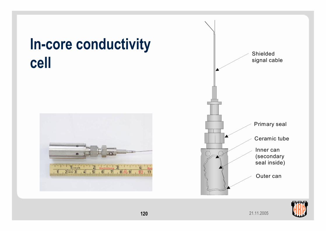
In-core conductivity cell• Based on Halden Pt in-core ECP reference electrode• Pt sensing element surrounded by a second Pt cylinder.
Additional signal cable fitted• Apply current and determine conductivity from voltage
difference between the 2 Pt cylinders• Prototype sensors tested under PWR conditions, both in
the Joint Programme (PWR IASCC test, IFA-657) and under bilateral projects
• Plans are to evaluate the sensor under BWR conditions• Low conductivity electrolyte
21.11.2005120
In-core conductivity cell
Inner can(secondaryseal inside)
Shielded signal cable
Primary seal
Ceramic tube
Outer can
21.11.2005121
On-line potential drop corrosion monitor• In-core corrosion of fuel cladding traditionally monitored by
taking measurements during reactor shutdowns• Can only determine average corrosion rates• On-line corrosion monitor based on dc potential drop method
developed for on-line crack growth measurements• Attach current and potential wires to the end plugs of the fuel
rod• Apply current and measure resulting potential drop at different
positions on the end plugs• Relate potential drop to clad thickness through out-of-core
calibration• Accuracy ±2 µm• A monitor is planned to be included in the new PWR clad
corrosion test

21.11.2005122
Schematic of monitor
21.11.2005123
Controlled distance electrochemical techniques (CDE)
• Conventional electrochemical techniques have sample and counter electrode separated by a few mm / cm
• Conductivity of BWR coolant is too low for a current to flow
• CDE: reduce electrode separation to below 100 µm• Development work performed by VTT: a bellows system
has been developed to control electrode separation
• In-core testing to be performed at Halden
21.11.2005124
CDE - measurements
• Depending on electrode separation and applied electrical conditions (ac, dc), can investigate:• Electronic properties of oxide films• Oxidation / reduction kinetics• Release rate of soluble corrosion products
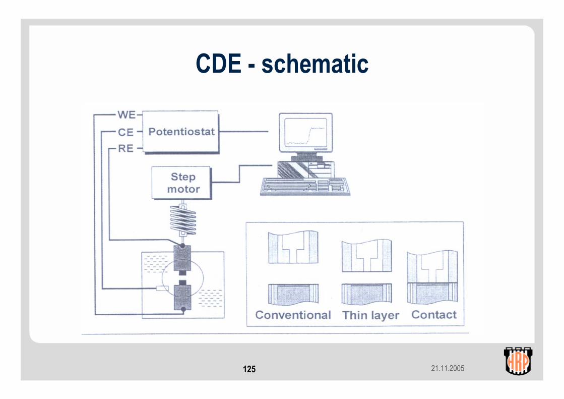
21.11.2005125
CDE - schematic
21.11.2005126
Electrochemical impedance spectroscopy (EIS)
• Used for on-line monitoring of oxide growth on Zircaloy fuel cladding or other reactor materials
• Apply a variable ac voltage to the sample and measure impedance with frequency of applied voltage
• Advantages of the technique:• Low pertubation signals that do not disturb system• Can be used in low conductivity media• Non destructive
• Calculate oxide thickness from an equivalent electrical circuit (capacitor with plate separation equal to oxide thickness)
21.11.2005127
EIS - development
• In the Joint programme, development work carried out by University of Gothenburg
• Work showed that long signal cables should not prevent data acquisition
• Test geometries: two-electrode configuration, with Zircaloy test and counter electrodes• Test electrode placed inside a concentric counter electrode• Identical electrodes placed alongside one another
21.11.2005128
EIS – development (contd.)
• Bilateral studies have shown that a more traditional three-electrode configuration gives better results:• Platinum mesh counter electrode, surrounding test electrode• Platinum reference electrode
• Length of signal cables minimised, by locating potentiostats and computers to run the tests in the reactor hall
• Measurements can be controlled by remote access to these computers

21.11.2005129
ECP reference electrode development• Electrochemical corrosion potential (ECP) is the potential
difference between a sample and the standard hydrogen electrode (SHE).
• ECP is an indirect measurement of the potential across the metal-solution boundary, and thus of the driving force for corrosion.
• ECP measured mainly in BWRs:• SCC of sensitised stainless steel significantly reduced below –
230 mVSHE⇒ hydrogen water chemistry, noble metal addition
• In-core ECP measurements allow link-up with R&D work
21.11.2005130
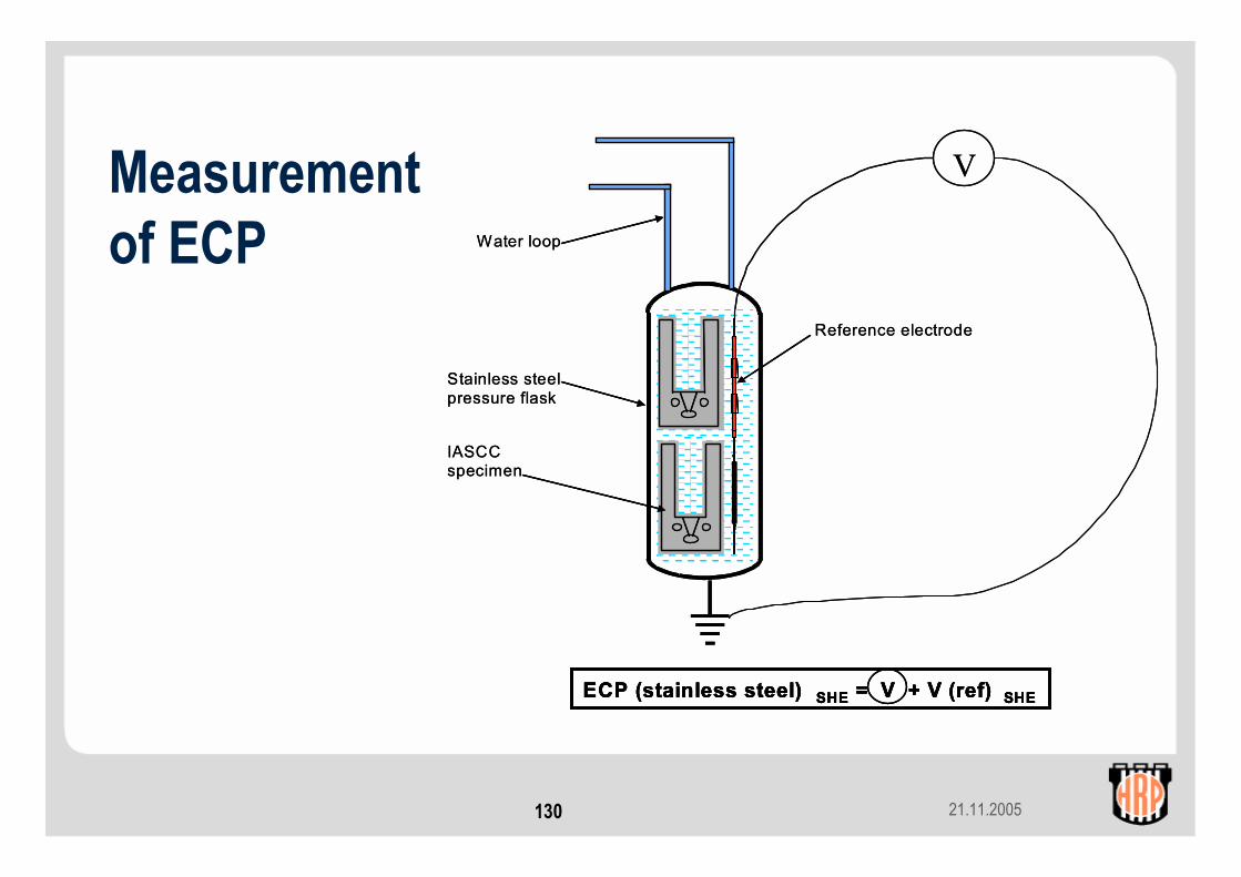
Measurement of ECP
Stainless steel pressure flask
Water loop
V
Reference electrode
IASCC specimen
ECP (stainless steel) SHE = V + V (ref) SHE
Stainless steel pressure flask
Water loop
V
Reference electrode
IASCC specimen
ECP (stainless steel) SHE = V + V (ref) SHEECP (stainless steel) SHE = V + V (ref) SHEECP (stainless steel) SHE = V + V (ref) SHE
21.11.2005131
ECP reference electrodes: development• Halden platinum electrode is reliable, but Pt electrodes do not
give SHE values in oxygenated water• Palladium electrode shows promise for use in oxygenated
water (IFA-658). Further testing and calibration is required.• For reliable ECP measurements, two different reference
electrode types should be used. Fe/Fe3O4 electrodes can be used in both hydrogenated and oxygenated water.
• A prototype Fe/Fe3O4 electrode has been constructed and tested. The electrode seal was leaktight during 3 temperature cycles.
• In-core testing planned in the BWR IASCC experiment, IFA-670
21.11.2005132
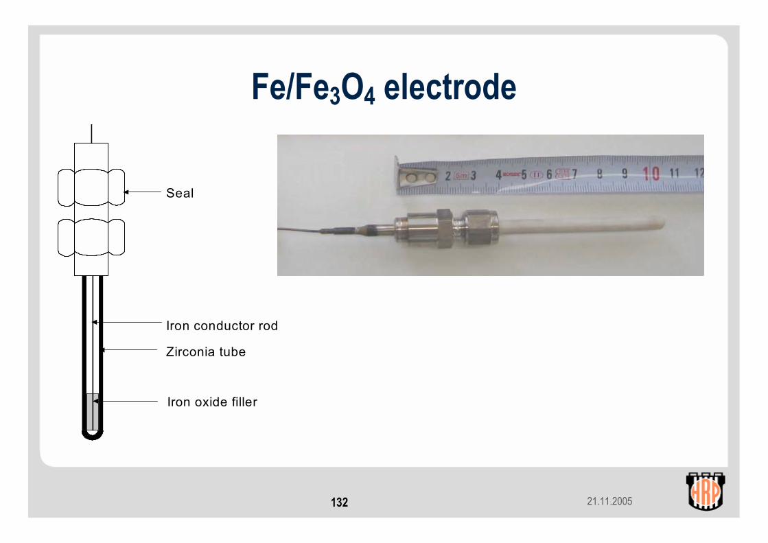
Fe/Fe3O4 electrode
Seal
Iron conductor rod
Zirconia tube
Iron oxide filler
21.11.2005133
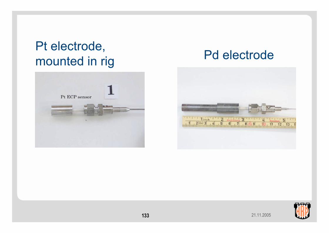
Pt electrode,mounted in rig Pd electrode
21.11.2005134
SummaryWell-qualified in-core measurement data from test reactors are valuable and:
• supplement LTA programmes ( and PIE campaigns)
• supplement out-of-pile studies ( on separate effects)
• enhance the understanding of basic mechanismsaffecting fuel & materials behaviour
• provide basis for detailed modelling of steady stateand transient behaviour of LWR fuel

21.11.2005135
That’s all we had time for, folks! THE END


![LAMMPS Features and Capabilities - Indico [Home]indico.ictp.it/event/a13190/session/11/contribution/61/material/0/... · LAMMPS Features and Capabilities Steve Plimpton Sandia National](https://img.dokumen.tips/doc/110x75/5b8c0a7209d3f21d638c5313/lammps-features-and-capabilities-indico-home-lammps-features-and-capabilities.jpg)