Embed Size (px)
Citation preview

Technical Bulletin
AA–304 1996 Audi of America, Inc.
Subject:
Model(s):
Group:
Number:
Date:
Central Locking System
m.y. 97 �
0196–11Nov. 29, 1996Cabriolet
The following Repair Manual pages are newand will be integrated with the next RepairManual update.

1
Remote unit for central lockingoperation, coding and erasing
Memory addresses, coding
On vehicles with remote-control central locking, every new or non-encoded remote unit must first be re-coded for the central lockingcontrol module.
– Switch ignition on; leave key in ignition.
– Mechanically lock vehicle at left front door, using second key.
– On remote unit, press “Open” button once. A short horn signalwill sound.
Note:♦ The “Open” button is pressed once for programming the first, or
a single, remote unit.♦ When programming additional remote units for the second, third
or fourth memory addresses, press the “Open” button two,three or four times, in one-second intervals.
♦ Example: press the “Open” button once, wait 1 second, thenpress once again to program the second remote unit.
– After 6 seconds, press “Open” button once to activate the codingprocess.

2
The remote unit will now be coded, and it can be used to unlock thecentral locking system.
– Switch ignition off.
Note:The key must be removed from ignition before the remote unit canbe used to lock the vehicle.
The coding process can be repeated up to 4 times for additional re-mote units. In between each remote unit coding, the ignition mustbe switched off.

3
Memory addresses, erasing
Note:It is possible to erase the memory, e.g. if the customer has lost aremote unit. Proceed as follows.
– Switch ignition on with key.
– Mechanically lock vehicle at left front door, using second key.
– On remote unit, press “Open” button 5 times in one-second in-tervals. A short horn signal will sound.
– Then after 6 seconds, press “Open” button once to activatememory erasing process.
Memory is now erased, and the central locking system can no long-er be operated by the remote unit.
– Switch ignition off.
As many as 4 new remote units can now be coded ⇒ page 1.
4
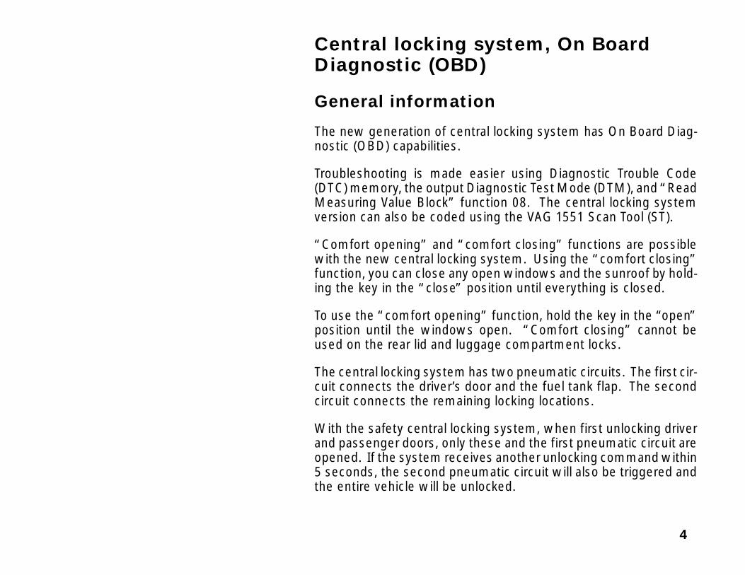
Central locking system, On BoardDiagnostic (OBD)
General information
The new generation of central locking system has On Board Diag-nostic (OBD) capabilities.
Troubleshooting is made easier using Diagnostic Trouble Code(DTC) memory, the output Diagnostic Test Mode (DTM), and “ReadMeasuring Value Block” function 08. The central locking systemversion can also be coded using the VAG 1551 Scan Tool (ST).
“Comfort opening” and “comfort closing” functions are possiblewith the new central locking system. Using the “comfort closing”function, you can close any open windows and the sunroof by hold-ing the key in the “close” position until everything is closed.
To use the “comfort opening” function, hold the key in the “open”position until the windows open. “Comfort closing” cannot beused on the rear lid and luggage compartment locks.
The central locking system has two pneumatic circuits. The first cir-cuit connects the driver’s door and the fuel tank flap. The secondcircuit connects the remaining locking locations.
With the safety central locking system, when first unlocking driverand passenger doors, only these and the first pneumatic circuit areopened. If the system receives another unlocking command within5 seconds, the second pneumatic circuit will also be triggered andthe entire vehicle will be unlocked.

5
If the rear lock is operated only once, the driver and passenger doorsremain locked. After approx. 5 seconds the rear lid and/or luggagecompartment flaps are re-locked automatically.
The interior lighting is brightened or dimmed within approx. 1.5 se-conds. Luggage compartment illumination is controlled by the cen-tral locking pump using the rear lid or luggage compartment contactswitches. When the rear lid is open, the illumination is switched offafter a speed threshold is exceeded (approx. 5 km/h or 3 mph).
Remote-control system changes, m.y. 1997 ➤
♦ The radio-frequency operated receiver is now a part of the centrallocking/alarm system/interior light delay control module -V94-, in-tegrated with the central locking pump. The separate centrallocking system control module for remote control operation isdiscontinued.
♦ The antenna of the radio-frequency operated remote control is in-tegrated into the wiring harness.
6
If no door or lid is opened within 60 seconds after the central lockingsystem is opened using a radio-frequency operated remote unit,the central locking system locks again.
If the anti-theft warning system is set, the central locking systemcan not be opened using the interior switch.
Confirmation can be set to trigger a short tone of the anti-theft warn-ing system horn or brief operation of the 4-way flashers. The centrallocking can also be coded in such a way that there is no confirma-tion.
Confirmation of radio-frequency operated remote control can bedisplayed by triggering the 4-way flashers.

7
Central locking system, On BoardDiagnostic (OBD)
Test requirements
♦ Fuses OK (check using appropriate wiring diagram)
♦ VAG 1551 Scan Tool (ST) connected ⇒ page 41.
Notes:♦ If the display is blank, check voltage supply to VAG 1551 scan tool
using the wiring diagram.♦ Additional operating instructions can be obtained by using the
HELP button on the Scan Tool.♦ Press the → button to advance the program sequence.
♦ Incorrect input can be cancelled using the -C- button.
♦ “Automatic Test Sequence” address word 00 can be carried outin “Rapid data transfer” operating mode 1. In this program, DTCmemory of all of the vehicle’s control modules are automaticallychecked.
– Switch printer on by pressing the Print button, indicator light inbutton lights up.
– Press button -1- for “Rapid data transfer” operating mode 1.
Indicated on displayRapid data transfer HELP
Insert address word XX

8
Address word 35: Central Locking
– Press buttons -3- and -5- to insert “Central Locking” addressword 35.
Indicated on display
– Press -Q-button to confirm input.
Indicated on display (after approx. 5 sec.):
Example:
♦ 8L0862257B: Control module identification
♦ CV-Pump, Alarm, RC: Component designation
♦ D04: Software version
♦ Coding 11932: Control module coding
♦ WSC 06812: Dealership code
– Press → button to advance through program sequence.
Rapid data transfer Q
8L0862257B CV-Pump, Alarm, RC D04 →Coding 11932 WSC 06812

9
If one of these messages is indicated on the display:
Troubleshooting wiring connections for Data Link Connector (DLC)⇒ Electrical Wiring Diagrams, Troubleshooting & Component Loca-tions binder
Indicated on display
– Press HELP button to print out list of possible functions.
– Press → button to advance program sequence.
Rapid data transfer HELP
Control module does not answer
Rapid data transfer HELP
Error in communication link
Rapid data transfer HELP
K wire not switching to Ground
Rapid data transfer HELP
K wire not switching to B+
Rapid data transfer HELP
Select function XX

10
On Board Diagnostic functions Page
02 - Check DTC Memory 11
03 - Output Diagnostic Test Mode (DTM) 21
05 - Erase DTC Memory 25
06 - End Output 27
07 - Code Control Module 28
08 - Read Measuring Value Block 36

11
Check DTC memory (function 02)
Note:The malfunction information displayed is not updated continuously,only when On Board Diagnostic (OBD) program is initiated or with“Erase DTC memory” function 05.
– Press print button to switch printer on, indicator light in the buttonlights up.
Indicated on display
– Press buttons -0- and -2 to select “Check DTC Memory” function02.
Indicated on display
– Press -Q- button to confirm input.
Indicated on display (number of malfunctions stored)
The stored malfunctions are displayed in sequence and printedout.
– Go to the DTC table with malfunctions printed out and repair asneeded ⇒ page 13.
Rapid data transfer HELP
Select function XX
Rapid data transfer Q
02 – Check DTC memory
X DTC recognized →

12
If “No DTC recognized” the program goes back to the starting posi-tion after pressing the → button.
Indicated on display
If something else is indicated on the display:⇒ Operating instructions for scan tool
– Press buttons -0- and -6- to select “End Output” function 06 ⇒page 27.
– Switch ignition off and disconnect scan tool from Data Link Con-nector (DLC).
No DTC recognized →
Rapid data transfer HELP
Select function XX
13
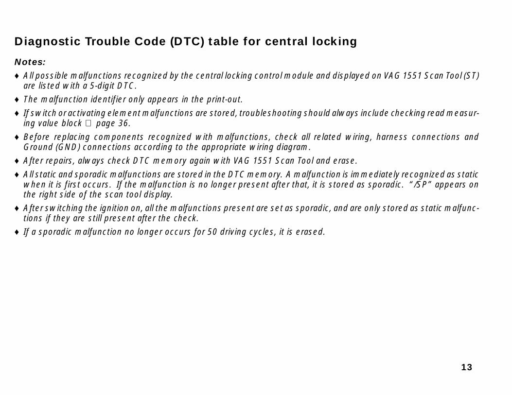
Diagnostic Trouble Code (DTC) table for central locking
Notes:♦ All possible malfunctions recognized by the central locking control module and displayed on VAG 1551 Scan Tool (ST)
are listed with a 5-digit DTC.♦ The malfunction identifier only appears in the print-out.
♦ If switch or activating element malfunctions are stored, troubleshooting should always include checking read measur-ing value block ⇒ page 36.
♦ Before replacing components recognized with malfunctions, check all related wiring, harness connections andGround (GND) connections according to the appropriate wiring diagram.
♦ After repairs, always check DTC memory again with VAG 1551 Scan Tool and erase.
♦ All static and sporadic malfunctions are stored in the DTC memory. A malfunction is immediately recognized as staticwhen it is first occurs. If the malfunction is no longer present after that, it is stored as sporadic. “/SP” appears onthe right side of the scan tool display.
♦ After switching the ignition on, all the malfunctions present are set as sporadic, and are only stored as static malfunc-tions if they are still present after the check.
♦ If a sporadic malfunction no longer occurs for 50 driving cycles, it is erased.

14
Output on printerof VAG 1551
Possible Malfunction Cause Malfunction Elimination
01360
Open ATW switch
♦ Short circuit toGround
♦ Short circuit to Ground (GND) in wiringconnection 1)
– Repair according to wiring diagram⇒ Electrical Wiring Diagrams, Trouble-
shooting & Component Locations binder
♦ Door contact switch–driver’s side -F2-faulty
– Check switch and replace if necessary
01361
Close ATW switch
♦ Short circuit toGround
♦ Short circuit to Ground (GND) in wiringconnection 1)
– Repair according to wiring diagram⇒ Electrical Wiring Diagrams, Trouble-
shooting & Component Locations binder
♦ Door contact switch–passenger’s side-F3- faulty
– Check switch and replace if necessary
1) The malfunction is stored if there is Ground (GND) connection for longer than 1 min., e.g. because of incorrect op-eration of the central locking. Carry out malfunction repairs only when there are complaints, otherwise just erasethe DTC memory ⇒ page 25.

15
Output on printerof VAG 1551
Malfunction EliminationPossible Malfunction Cause
01362
Close Switch for Tail-gate–F124
♦ Short circuit toGround
♦ Short circuit to Ground (GND) in wiringconnection 1)
– Repair according to wiring diagram⇒ Electrical Wiring Diagrams, Trouble-
shooting & Component Locations binder
♦ Trunk lock alarm/central locking switch-F124- faulty
– Check switch -F124- and replace if neces-sary
01363
Switch for CL; DriversDoor–F59
♦ Incorrect signal ♦ This display can appear, depending onthe system. There is no malfunction inthe driver’s door central locking systemswitch -F59-. 2)
– Ignore malfunction display and eraseDTC memory ⇒ page 25
1) The malfunction is stored if there is Ground (GND) connection for longer than 1 min., e.g. because of incorrect op-eration of the central locking. Carry out malfunction repairs only when there are complaints, otherwise just erasethe DTC memory ⇒ page 25.
2) The malfunction is stored if the input status of the central locking pump has not changed before/after the closing/opening of central locking system.
16
Output on printerof VAG 1551
Malfunction EliminationPossible Malfunction Cause
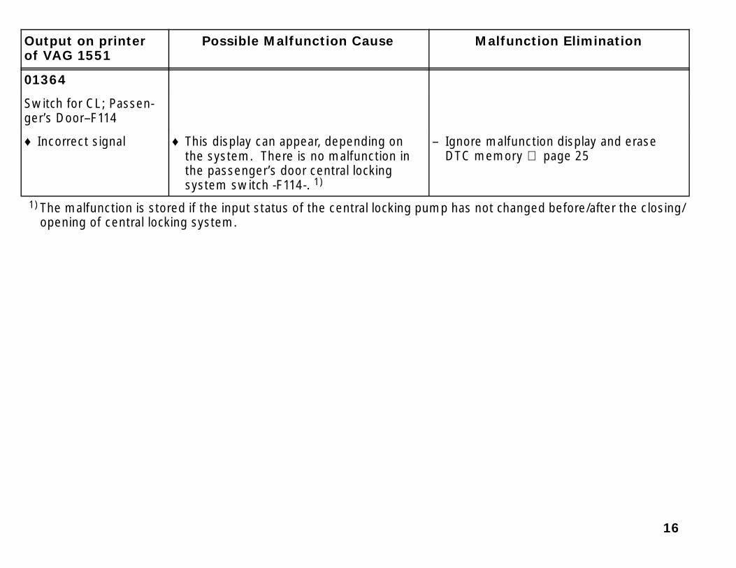
01364
Switch for CL; Passen-ger’s Door–F114
♦ Incorrect signal ♦ This display can appear, depending onthe system. There is no malfunction inthe passenger’s door central lockingsystem switch -F114-. 1)
– Ignore malfunction display and eraseDTC memory ⇒ page 25
1) The malfunction is stored if the input status of the central locking pump has not changed before/after the closing/opening of central locking system.

17
Output on printerof VAG 1551
Malfunction EliminationPossible Malfunction Cause
01365
Lock/Unlock Switch But-ton Int.
♦ Short circuit toGround
♦ Short circuit to Ground (GND) in wiringconnection 1)
– Repair according to wiring diagram⇒ Electrical Wiring Diagrams, Trouble-
shooting & Component Locations binder
♦ Switch for interior lock, driver side -E150-faulty
– Check switch -E150- and replace if nec-essary
♦ Short circuit to B+ ♦ Short circuit in wiring connection – Repair according to wiring diagram⇒ Electrical Wiring Diagrams, Trouble-
shooting & Component Locations binder
♦ Switch for interior lock, driver side -E150-faulty
– Check switch -E150- and replace if nec-essary
1) The malfunction is stored if there is Ground (GND) or positive (B+) connection for longer than 1 min., e.g. becauseof incorrect operation of the central locking. Carry out malfunction repairs only when there are complaints, other-wise just erase the DTC memory ⇒ page 25.

18
Output on printerof VAG 1551
Malfunction EliminationPossible Malfunction Cause
01366
Opened Via CrashSignal
♦ Carry out output diagnostic test mode onairbag control module -J234-
♦ Airbag control module -J234- hastriggered
– Erase DTC memory ⇒ page 25
01367
Switch on Via CL Pump ♦ Pressure in pneumatic lines too low♦ Central locking-pump faulty
– Check pneumatic lines for leaks– Check central locking pump– Check all actuating components of cen-
tral locking and replace if necessary
01368
Alarm Via LuggageCompartment Switch
♦ Anti-theft alarm activated byunauthorized opening of rear lid
– Erase DTC memory ⇒ page 25
♦ Trunk lid alarm switch -F123- is faulty – Replace contact switch -F123-

19
Output on printerof VAG 1551
Malfunction EliminationPossible Malfunction Cause
01369
Alarm Via BonnetSwitch
♦ Anti-theft alarm activated byunauthorized opening of engine hood
– Erase DTC memory ⇒ page 25
♦ Hood alarm switch -F120- is faulty – Replace contact switch -F120-
01370
Alarm Via Interior Scan-ning
♦ Output test carried out on controlmodule for ultra-sound sensors -J347-
– Erase DTC memory ⇒ page 25
♦ Anti-theft warning system triggered bytriggering of ultrasonic interior monitoring
– Erase DTC memory ⇒ page 25
♦ Malfunction on ultrasonic interior monitor – Repair using diagnosis of interior moni-toring
⇒ Repair Manual, Electrical Equipment, Re-pair Group 96

20
Output on printerof VAG 1551
Malfunction EliminationPossible Malfunction Cause
01371
Alarm Via Door ContactSwitch Driv. Side
♦ Anti-theft alarm activated byunauthorized opening of driver’s door
– Erase DTC memory ⇒ page 25
♦ Door contact switch–driver’s side -F2-faulty
– Replace contact switch -F2-
01372
Alarm Via Door ContactSwitch Rear PS
♦ Anti-theft warning system triggered byunauthorized opening of passenger’sdoor and/or rear doors
– Erase DTC memory ⇒ page 25
♦ Door contact switches -F3-, -F10-, -F11-faulty
– Replace contact switches -F3-, -F10-,-F11-
01373
Alarm Via Radio GroundTerminal
♦ Anti-theft warning triggered byunauthorized removal of radio
– Erase DTC memory ⇒ page 25
♦ Interruption in Ground (GND) connectionfor anti-theft warning system
– Connect Ground (GND) connection

21
Output on printerof VAG 1551
Malfunction EliminationPossible Malfunction Cause
01374
Alarm Via Terminal 15 ♦ Anti-theft system triggered byunauthorized starting (short circuit)
– Erase DTC memory ⇒ page 25
♦ Short circuit between terminal 30 andterminal 15
– Repair according to wiring diagram⇒ Electrical Wiring Diagrams, Trouble-
shooting & Component Locations binder
01389
Tailgate Open Switch -F124-
♦ Short circuit toGround
♦ Short circuit to Ground (GND) in thewiring connection
– Repair according to wiring diagram⇒ Electrical Wiring Diagrams, Trouble-
shooting & Component Locations binder
♦ Trunk lock alarm/central locking switch-F124- faulty
– Check switch -F124- and replace if neces-sary
22
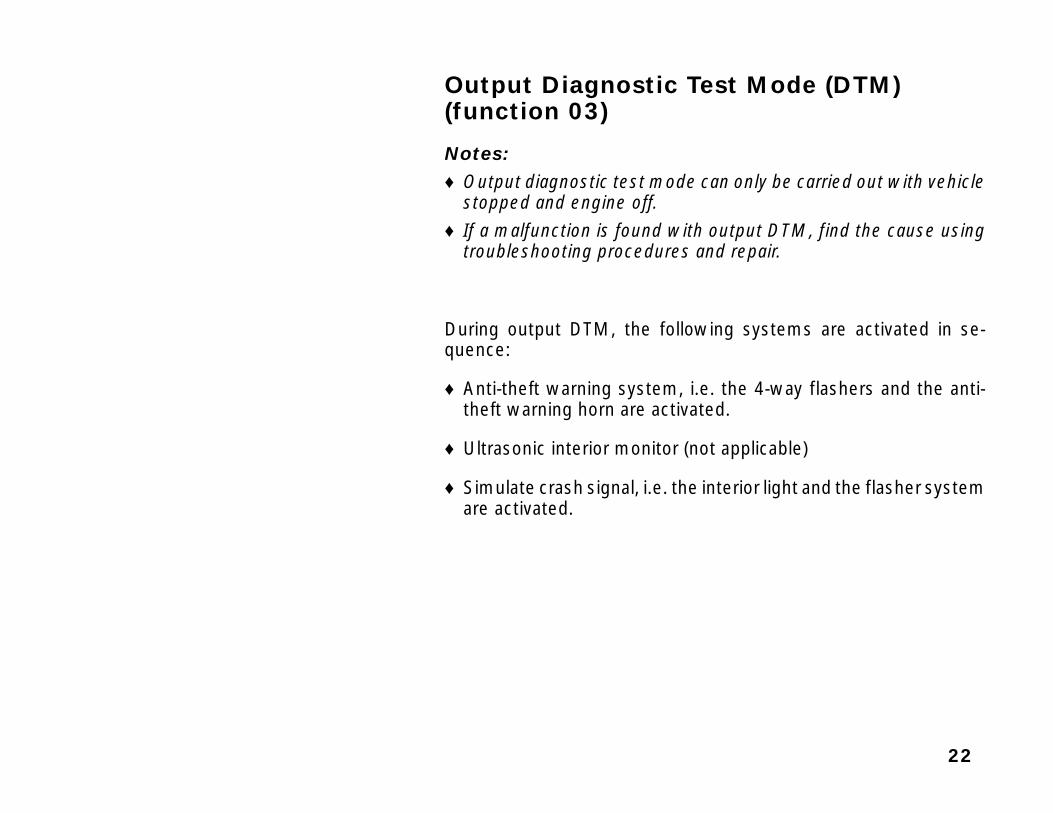
Output Diagnostic Test Mode (DTM) (function 03)
Notes:♦ Output diagnostic test mode can only be carried out with vehicle
stopped and engine off.♦ If a malfunction is found with output DTM, find the cause using
troubleshooting procedures and repair.
During output DTM, the following systems are activated in se-quence:
♦ Anti-theft warning system, i.e. the 4-way flashers and the anti-theft warning horn are activated.
♦ Ultrasonic interior monitor (not applicable)
♦ Simulate crash signal, i.e. the interior light and the flasher systemare activated.

23
Initiating output DTM
– Press buttons -0- and -3- to select “Output Diagnostic Test Mode”function 03.
Indicated on display
– Press -Q- button to confirm input.
Output DTM for ultrasonic interior monitor starts.
Indicated on display
The 4-way flashers and the anti-theft warning horn are triggered bythe anti-theft warning system.
– Press → button and alarm is shut off.
Indicated on display
– Press → button.
Rapid data transfer Q
03 – Output Diagnostic Test Mode
Output Diagnostic Test Mode →Create Active Alarm
Output Diagnostic Test Mode →Next Final Ctrl: Operate →

24
Indicated on display
– Press → button.
Indicated on display
– Press → button.
Indicated on display
The flasher system and the interior illumination are triggered.
– Press → button.
Indicated on display
– Press → button to end output DTM.
The VAG 1551 scan tool returns to “Select function” mode.
Indicated on display
Function is unknown or
cannot be carried out at the moment
Output Diagnostic Test Mode →Next Final Ctrl: Operate →
Output Diagnostic Test Mode →Simulate Crash Signal
Output Diagnostic Test Mode →END
Rapid data transfer HELP
Select function XX

25
Erase DTC Memory (function 05)
Note:In “Erase DTC Memory” function 05, any malfunctions stored inDTC memory are automatically output. If DTC memory cannot beerased, check DTC memory again and repair malfunctions.
Requirements
Check DTC memory ⇒ page 11.
All malfunctions eliminated.
After checking DTC memory
Indicated on display
– Press buttons -0- and -5- to select “Erase DTC Memory” function05.
Indicated on display
– Press -Q- button to confirm input.
Indicated on display
This means the DTC memory is erased.
– Press → button.
Rapid data transfer HELP
Select function XX
Rapid data transfer Q
05 – Erase DTC Memory
Rapid data transfer →DTC Memory is erased

26
Indicated on display (VAG 1551 scan tool returns to “Select func-tion” mode)
Note:If either of these messages are indicated on the display, the testprocedure is not complete.
– Follow the test sequence exactly.
– Check DTC memory first, and eliminate malfunctions as neces-sary. Then erase DTC memory.
Rapid data transfer HELP
Select function XX
Attention!
DTC Memory is not erased
Rapid data transfer →DTC Memory is not interrogated
27
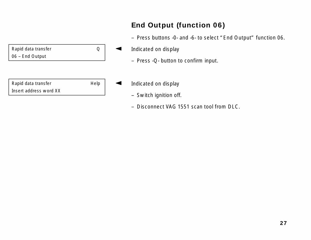
End Output (function 06)
– Press buttons -0- and -6- to select “End Output” function 06.
Indicated on display
– Press -Q- button to confirm input.
Indicated on display
– Switch ignition off.
– Disconnect VAG 1551 scan tool from DLC.
Rapid data transfer Q
06 – End Output
Rapid data transfer Help
Insert address word XX
28
Code Control Module (function 07)
The two central locking system variations can be coded accordingto the possible function/equipment variations.
Central locking system variations:
♦ Central locking with anti-theft warning system
♦ Central locking with radio-frequency operated remote control andanti-theft warning system
Notes:♦ Basic functions of the central locking system variations are listed
in the standard coding table ⇒ page 29.
♦ If a customer requests a special, individual coding of the centrallocking system, use the questions ⇒ page 30 to determine thecorrect system coding.
29
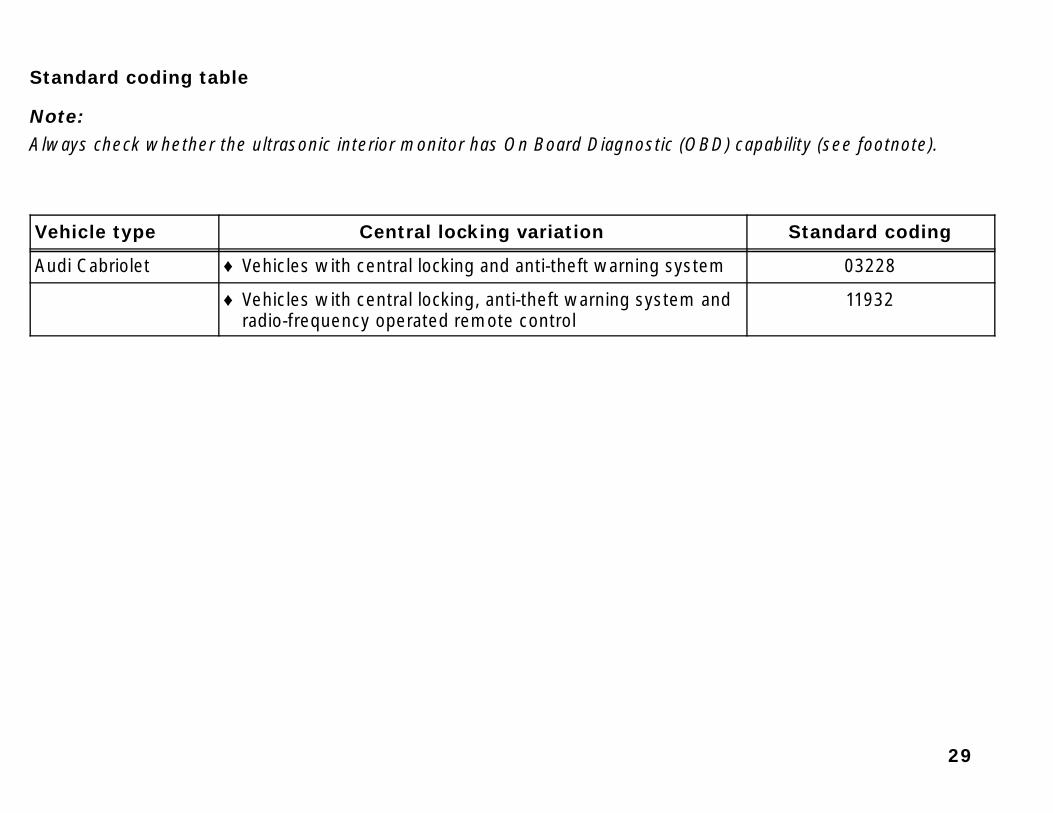
Standard coding table
Note:Always check whether the ultrasonic interior monitor has On Board Diagnostic (OBD) capability (see footnote).
Vehicle type Central locking variation Standard coding
Audi Cabriolet ♦ Vehicles with central locking and anti-theft warning system 03228
♦ Vehicles with central locking, anti-theft warning system andradio-frequency operated remote control
11932

30
Coding questions for individual central locking functions
Notes:♦ First determine which central locking version this vehicle has (e.g. what central locking and anti-theft warning sys-
tem).♦ Please make a copy of the applicable table for the current vehicle.
♦ Answer all questions in the table with “yes” or “no”. In the last column, enter your copy of the number of answers.
♦ If in doubt, please ask the customer what central locking functions are desired.
♦ Please total all the results from top to bottom. The total gives the valid control module coding. Add the figures upagain as a check.
♦ Examples of coding calculations ⇒ page 33.

31
Table I: vehicles with central locking and anti-theft warning system
Vehicles with central locking and anti-theft warning system: Answer
1. Is the vehicle an Cabriolet? No = 0 Yes = 16 16
2. Will the vehicle have a single door opening and a rear lid subsequentlocking (safety central locking)?
No = 0 Yes = 4
3. Will the power windows be shut off with driver’s door open and igni-tion off (USA door locking logic)? (USA = yes)
No = 0 Yes = 2048 2048
4. Is an anti-theft warning system installed in the vehicle? No = 0 Yes = 8
5. Will the anti-theft warning system setting be confirmed triggering the4-way flashers? 1)
No = 0 Yes = 4096
6. Will the anti-theft warning system setting be confirmed triggering theanti-theft warning horn? 1)
No = 0 Yes = 1024
7. Does the vehicle have ultrasonic interior monitor? (Cabriolet = no) No = 128 Yes = 0 128
Total (coding):1) Only one of questions 5 and 6 can be answered with “yes”, but both can be answered with “no”.

32
Table II: vehicles with central locking and anti-theft warning system
Vehicles with central locking, radio-frequency operatedremote control and anti-theft warning system:
Answer
1. Is the vehicle an Cabriolet? No = 0 Yes = 16 16
2. Will the vehicle have a single door opening and a rear lid subsequentlocking (safety central locking)?
No = 0 Yes = 4
3. Will the power windows be shut off with driver’s door open and igni-tion off (USA door locking logic)? (USA = yes)
No = 0 Yes = 2048 2048
4. Will the anti-theft warning system be activated? No = 0 Yes = 8
5. Will the anti-theft warning system setting be confirmed triggeringthe 4-way flashers? 1)
No = 0 Yes = 4096
6. Will the anti-theft warning system setting be confirmed triggeringthe anti-theft warning horn? 1)
No = 0 Yes = 1024
7. Does the vehicle have ultrasonic interior monitor? (Cabriolet = no)
No = 128 Yes = 0 128
8. Will the radio-frequency operated remote control be activated? No = 0 Yes = 8192
9. Will the locking/unlocking of central locking system be confirmedwith remote control by triggering 4-way flashers?
No = 0 Yes = 512
10. Will a single door opening and the rear lid subsequent locking (safe-ty central locking) also be possible with the radio-frequencyoperated remote control?
No = 16384 Yes = 0
Total (coding):1) Only one of questions 5 and 6 can be answered with “yes”, but both can be answered with “no”.

33
Example of a special central locking codingThis is a case of an Cabriolet with central locking and anti-theft warning system. A safety central locking system isdesired and setting the anti-theft warning system will be confirmed by triggering the 4-way flashers.
Vehicles with central locking and anti-theft warningsystem:
Answer
1. Is the vehicle an Cabriolet? No = 0 Yes = 16 Yes = 16
2. Will the vehicle have a single door opening and a rear lid subse-quent locking (safety central locking)?
No = 0 Yes = 4 Yes = 4
3. Will the power windows be shut off with driver’s door open andignition “off” (USA door locking logic)? (USA = yes)
No = 0 Yes = 2048 Yes = 2048
4. Will the anti-theft warning system be activated? No = 0 Yes = 8 Yes = 8
5. Will setting the anti-theft warning system setting be confirmed bytriggering the 4-way flashers? 1)
No = 0 Yes = 4096 Yes = 4096
6. Will setting the anti-theft warning system setting be confirmed bytriggering the anti-theft warning horn? 1)
No = 0 Yes = 1024 No = 0
7. Does vehicle have ultrasonic interior monitor? (Cabriolet = no) No = 128 Yes = 0 No = 128
Total (coding): 63001) Only one of questions 5 and 6 can be answered with “yes”, but both can be answered with “no”.

34
Initiating central locking system coding
Indicated on display
– Press buttons -0- and -7- to select “Code Control Module” func-tion 07.
– Press -Q- button to confirm input.
Indicated on display
– Enter a valid 5-digit code using buttons (for example 03228).
Note:Determine the valid coding for the current central locking pump us-ing the standard coding table ⇒ page 29 or the answers for individ-ual coding ⇒ page 30.
– Indicated on display
– Press -Q- button to confirm input.
Indicated on display
– End coding procedure by pressing the → button.
Rapid data transfer HELP
Select function XX
Code control module
Enter code number XXXXX (0–32000)
Code control module Q
Input code number 03228 (0–32000)
8L0862257A CV-Pump, Alarm →Coding 03228 WSC 06812

35
Indicated on display
– Press buttons -0- and -6- to select “End Output” function 06.
Indicated on display
– Press -Q- button to confirm input.
Note:“Read Measuring Value Block” function 08 can be used to checkthe central locking pump coding in display group 004 ⇒ page 40.
Rapid data transfer HELP
Select function XX
Rapid data transfer Q
06 – End Output

36
Read Measuring Value Block (function 08)
Initiating read measuring value block
Indicated on display
– Press buttons -0- and -8- to select “Read Measured Value Block”function 08.
Indicated on display
– Press -Q- button to confirm input.
Indicated on display
– Input display group number (for example 001) by pressing the but-tons and confirm by pressing the -Q- button.
The selected display group is displayed in standardized form.
Rapid data transfer Help
Select function XX
Rapid data transfer Q
08 – Read measured value block
Read measured value block Help
Input display group number XXX

37
Display group 001
Read measuring value block 01 → � Indicated on display
0 1 0 0 1 0 0 0 0 0 0 0 0 0 0
X X X
X
• Rear lid: 1 = open, 0 = closed• Luggage compartment light: 1 = light on, 0 = light off• Switch for rear lid unlocking (not applicable):
1 = activated, 0 = not activated• Motor for rear lid unlocking (not applicable):
1 = motor running, 0 = motor not running
XX
XX
• Actuator switch and/or interior switch on passenger’s door: 00 = not activated, 01 = locking, 10 = unlocking, 11 = not permitted
• Actuator switch and/or interior switch on driver’s door:00 = not activated, 01 = locking, 10 = unlocking, 11 = not permitted
X X X
• Passenger’s and back door: 1 = open, 0 = closed (USA: back doors only)• Driver’s door: 1 = open, 0 = closed (USA: driver’s and passenger’s doors)• Engine hood: 1 = open, 0 = closed
X X X X
Key position in the lock cylinders• Driver’s/passenger’s door, unlocking: 1 = key operated, 0 = key in center position• Driver’s/passenger’s door, locking: 1 = key operated, 0 = key in center position• Rear lid, unlocking: 1 = key operated, 0 = key in center position• Rear lid, locking; 1 = key operated, 0 = key in center position

38
Display group 002
Read measuring value block 02 → � Indicated on display
0 1 0 0 0 1 0 0 0 0 0
X X X
• Terminal 15: 1 = ignition on, 0 = ignition off• S-Contact: 1 = S-Contact on, 0 = S-Contact off• Ground signal from radio: 1 = radio installed, 0 = radio removed
X
X
X
X
• Radio-frequency operated remote unit “Open” button: 1 = activated, 0 = not activated
• Radio-frequency operated remote unit “Close” button: 1 = activated, 0 = not activated
• Radio-frequency operated remote unit “Rear lid” open button: 1 = activated, 0 = not activated (not applicable)
• Radio-frequency operated remote unit “Panic” button (USA only): 1 = activated, 0 = not activated
X X
X X
• Interior light control: 1 = interior light on, 0 = interior light off• Control wire for power window/sunroof:
1 = terminal 87 (holding the voltage supply), 0 = ground• “Comfort closing”: 1 = comfort closing activated, 0 = not activated• “Comfort opening” function: 1 = comfort opening activated, 0 = not activated
39
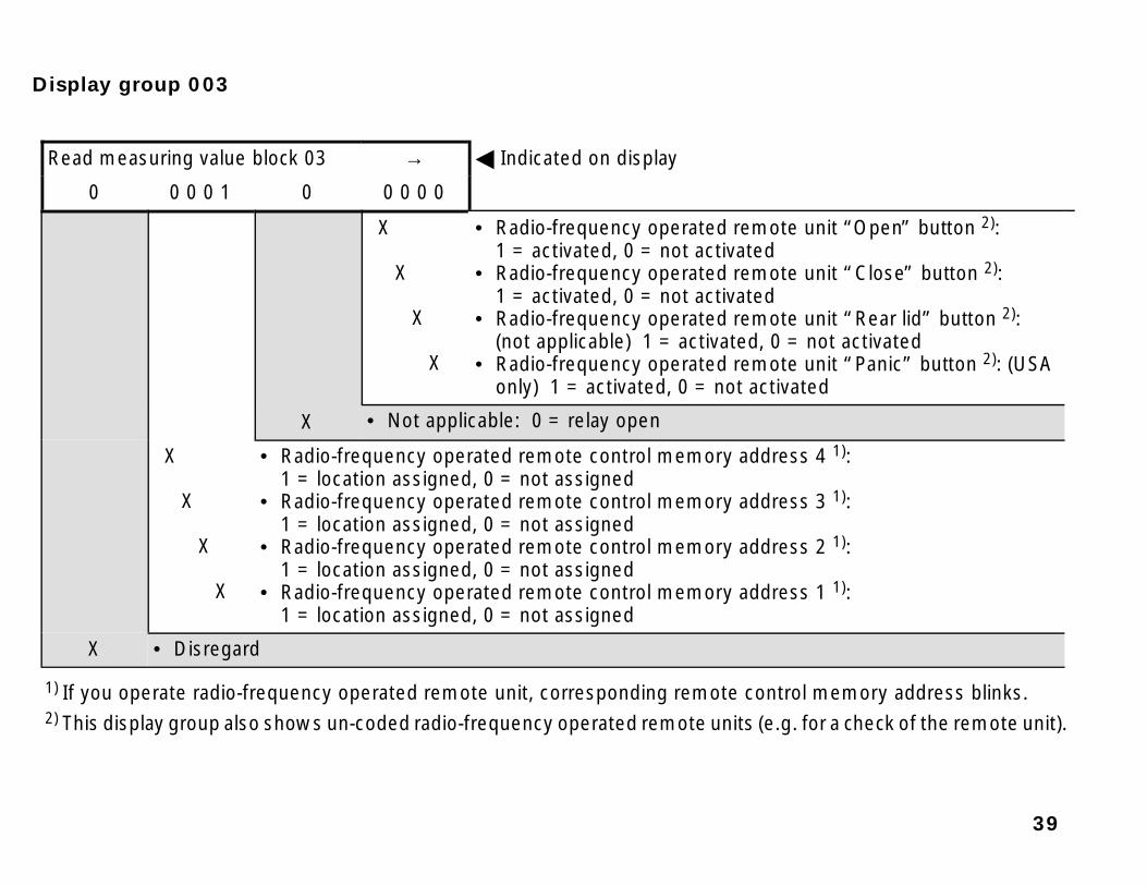
Display group 003
Read measuring value block 03 → � Indicated on display
0 0 0 0 1 0 0 0 0 0
X
X
X
X
• Radio-frequency operated remote unit “Open” button 2):1 = activated, 0 = not activated
• Radio-frequency operated remote unit “Close” button 2):1 = activated, 0 = not activated
• Radio-frequency operated remote unit “Rear lid” button 2):(not applicable) 1 = activated, 0 = not activated
• Radio-frequency operated remote unit “Panic” button 2): (USAonly) 1 = activated, 0 = not activated
X • Not applicable: 0 = relay open
X
X
X
X
• Radio-frequency operated remote control memory address 4 1): 1 = location assigned, 0 = not assigned
• Radio-frequency operated remote control memory address 3 1): 1 = location assigned, 0 = not assigned
• Radio-frequency operated remote control memory address 2 1): 1 = location assigned, 0 = not assigned
• Radio-frequency operated remote control memory address 1 1): 1 = location assigned, 0 = not assigned
X • Disregard
1) If you operate radio-frequency operated remote unit, corresponding remote control memory address blinks.2) This display group also shows un-coded radio-frequency operated remote units (e.g. for a check of the remote unit).

40
Display group 004
Read measuring value block 04 → � Indicated on display
0 1 0 1 0 0 1 0 0 0 0 0 0 0 0
X X X X
• Anti-theft warning system activated: 0 = no, 1 = yes• Safety central locking activated: 0 = no, 1 = yes• Disregard: Coding always 0• Disregard: Coding always 0
X X X X
• Disregard: Coding always 0• Disregard: Coding always 1• Disregard: Coding always 0• Vehicle is a Cabrio: 0 = no, 1 = yes
X X
X
X
• USA door logic coding 1): 0 = no, 1 = yes• Confirmation of the anti-theft warning system by way of the 4-way flashers:
0 = no, 1 = yes• Confirmation of anti-theft warning system by way of anti-theft warning horn:
0 = no, 1 = yes• Confirmation of the radio-frequency operated remote control by way of the 4-way
flashers: 0 = no, 1 = yes
X X
X
• Radio-frequency operated remote control activated: 0 = no, 1 = yes• Operation of safety central locking also possible with radio-frequency operated remote control: 1
= no, 0 = yes• Disregard: Coding always 0
1) Power window operation is disabled with ignition switched off and driver’s door open

A24-012524A-0125
A24-0125
V.A.G 1551/3
V.A.G 1551
1 34
25 6
7 8 90C Q
–
–
––
41
VAG 1551 Scan Tool (ST), connecting
Note:VAG 1552 can be used instead of VAG 1551. However no print-outcan be made with VAG 1552.
Test conditions
Battery voltage (B+) at least 11 volts
Ground (GND) connections on engine and transmission OK
Fuse OK
– Connect VAG 1551 (VAG 1552) scan tool to 16-pin Data Link Con-nector (DLC) to the left of steering column using adapter cableVAG 1551/3.
Indicated on display 1)
1) Both operating modes are displayed alternately.
Note:If display is blank, check voltage supply according to ⇒ “ElectricalWiring Diagrams, Troubleshooting & Component Locations” bind-er.
V.A.G. On Board Diagnostic HELP
1-Rapid data transfer
2-Blink code output

42
– Switch ignition on.
– Press PRINT button to turn printer on (indicator light in buttonlights up).
– Press button -1- for “Rapid data transfer” operating mode 1.
– Indicated on display
Note:After inserting “Automatic Test Sequence” address word 00 andconfirming with the -Q- button, VAG 1551 carries out a test se-quence automatically (checking DTC memory for all systems withrapid data transfer) and switches on the printer.
Rapid data transfer HELP
Insert address word XX

43

44


![[Distillation] - Towers Malfunctions (Kister)](https://img.dokumen.tips/doc/110x75/55cf9d79550346d033adc79f/distillation-towers-malfunctions-kister.jpg)