Embed Size (px)
Citation preview

Technical
& Testing
Equipment Revision 0 – 06/11/2015
This document contains proprietary information & is advanced subject to return upon demand. It is
issued on the expressed condition that it will not be used directly or indirectly in any way detrimental
to the interests of any companies within the O’Hara Group.
This document may not be reproduced in any way without the written permission of the QEHS
management or directorship of O’Hara Engineering Services Ltd.

Technical & testing
Equipment
TP Rev 00
Issue date:
01.02.15 Page 2 of 26
Contents Introduction .................................................................................................................................................................................. 3
Short Circuit, Protection & Discrimination Studies .................................................................................................................. 4
Power Quality Analysis ................................................................................................................................................................ 6
Earthing Testing ............................................................................................................................................................................ 8
Earthing & Ground Resistance Testing ................................................................................................................................ 8
Step & Touch Voltage ............................................................................................................................................................ 9
Transformer Testing & Maintenance ........................................................................................................................................ 2
Insulation Power Factor/Dissipation Factor Testing ........................................................................................................... 2
Capacitance Tests ................................................................................................................................................................. 2
Excitation Current Test ........................................................................................................................................................... 2
(Sweep) Frequency Response Analysis (SFRA/FRA) ......................................................................................................... 3
Transformer Turns Ratio .......................................................................................................................................................... 3
Phase Angle Deviation .......................................................................................................................................................... 4
Winding Resistance ................................................................................................................................................................ 4
Temperature Probes ............................................................................................................................................................... 4
Dry type Transformers ............................................................................................................................................................. 4
Oil Testing & Treatment .............................................................................................................................................................. 5
Oil Dielectric Strength Testing ............................................................................................................................................... 5
Oil Treatment ........................................................................................................................................................................... 5
Circuit Breaker Testing and Timing ....................................................................................................................................... 6
Primary & High Current Testing & Injection ............................................................................................................................. 8
Secondary Injection Protection Relay Testing & Calibration .............................................................................................. 9
A.C & D.C. High Voltage Testing ............................................................................................................................................ 11
D.C. High Voltage Testing ................................................................................................................................................... 11
A.C. High Voltage Testing ................................................................................................................................................... 11
Instrument Transformer Testing & Maintenance .................................................................................................................. 12
Current Transformer Analysis ............................................................................................................................................... 12
Voltage Transformer Turns Ratio ......................................................................................................................................... 12
Sulphur Hexafluoride Testing ............................................................................................................................................... 13
Partial Discharge Testing .......................................................................................................................................................... 14
Cable Identification and Fault Finding .................................................................................................................................. 15
Battery Discharge Testing .................................................................................................................................................... 16
General Testing .......................................................................................................................................................................... 17
Standard Testing ................................................................................................................................................................... 17
Structured Cable Testing ..................................................................................................................................................... 17
Training Course .......................................................................................................................................................................... 18
ISO Certification ......................................................................................................................................................................... 18

Technical & testing
Equipment
TP Rev 00
Issue date:
01.02.15 Page 3 of 26
Introduction
The integrity of any electrical installation once established, cannot simply be taken for granted.
Every electrical system, no matter how good the initial design and installation, undergoes changes
and deterioration throughout its lifetime. In normal circumstances, the requirements of the user also
change over time, and additions and alterations to the original system are inevitable. In many cases
these changes are not formally planned and managed, and their cumulative effect on the overall
installation can give rise to problems of power quality and overloading.
In addition to that, the protection initially afforded to the installation may become ineffective due to
developments in the distribution system, and may require further investigation and adjustment. This in
turn highlights a further problem, in that the operating times of many older protection devices are
unreliable, and those devices may require thorough testing to establish real operating parameters.
Transformers also require attention throughout their lifetime. The range of problems here spans a
spectrum from contamination by moisture and foreign particles, to coil deformation caused by
system faults or lightning. With these and several other problems in mind, O’HARA ENGINEERING
SERVICES Ltd. have developed a high level of expertise in the investigation and testing of new and
existing electrical installations. The company carries an exhaustive inventory of state of the art test
equipment, operated by fully trained and qualified staff. This brochure outlines the range of testing
and commissioning services available, together with details of the test equipment used. In short, if
there is a particular problem with your electrical installation we have the equipment and the trained
personnel to isolate and identify the source. A pre-requisite of this service is the timely production of
comprehensive reports and documentation. The latest generation of test equipment used by
O’Hara Engineering Services facilitates this, and ensures that clients and customers are provided with
an accurate assessment of the condition of their installations in the shortest possible time. This service
and our corporate commitment to our customers is now complimented by way of our Engineers
Ireland accredited training course which is available to consultants, contractors and industry.
So should you have a requirement for high quality testing and validation or should your staff require
electrical operation training we are on hand to help.

Technical & testing
Equipment
TP Rev 00
Issue date:
01.02.15 Page 4 of 26
Short Circuit, Protection & Discrimination Studies In order to fully evaluate the results of tests carried out under the current ETCI and CENELEC requirements it is
necessary to be able to establish both phase to phase and phase to earth faults at any point in an installation,
right down to the final sub circuit. In order to provide this, O'Hara Engineering Services Ltd use Amtech Power-
Net and Protect software.
Amtech Powernet Screen Shot
PowerNet Software has the following features:
Calculates Current & Voltage Distribution throughout the network during a fault.
Any Voltage can be entered. Voltages are automatically assigned to elements from the nodes to
which they are connected.
Supports 50Hz or 60Hz frequencies.
Database of resistance, reactance & zero impedance of cables is included.
Peak, Max & Min 3 Phase, 2 Phase to Earth Short Circuits can all be calculated.
Network Elements.
Utility- Network Supplies.
Generators- In Standby or Synchronous Mode.
Induction Motors.
Transformers- Any Voltage Ratio or Rating including Neutral Earthing.
Current- Limiting Reactors.
Cables.
Overhead Lines & Busbars.
Undefined Impedance- To represent any Impedance value.
Circuit breakers, Switches, Switch Fuses and Bus-Couplers.

Technical & testing
Equipment
TP Rev 00
Issue date:
01.02.15 Page 5 of 26
With Amtech Protect software, protective devices are selected from the comprehensive manufacturer's
database. This includes low voltage switchgear as well as the most sophisticated IDMT relays. LV & HV devices
are reflected to a Common Voltage Base. Protect also has the following features:-
A Single Line Diagram of the system can be displayed. This diagram is interactive and can be used to select
various elements of the system. Transformer Rated Current, Max LV Three Phase Fault Level, Transformer
Damage Point and LV Phase Earth Fault. These can all be calculated and displayed on screen. Adjustment of
devices on screen in 'real time' - allows instant observation of the differences between various trip units and
device settings. Device performance is much easier to understand than by inspection of technical catalogues
Amtech Powernet Screen Shot

Technical & testing
Equipment
TP Rev 00
Issue date:
01.02.15 Page 6 of 26
Power Quality Analysis Voltage, loads and harmonics in a network change over time. To detect a problem in a network it is necessary
to be able to monitor these changes in a reliable way. To do this we use various pieces of equipment including
Unilyzers, VIP & Fluke meters.
Unipower 812 Unilyzer
The Unipower 812 Unilyzer has eight channels with transducers for measuring
voltage and current .The system calculates true root mean square values for
voltage and current and it also calculate the active and reactive power,
apparent power and power factor. During measurement, an oscilloscope
picture of the signal for waveform Analysis is displayed. Harmonics can also
be measured and displayed in bar diagram or table format.
The Instrument software carries out analysis of the measured data against
international standards such as EN50160.
The Unilyzer measurers and records the following: -
Load analysis, V, A, W, VA, Var., kWh, kVArh, PF, cos (phi), IFL, PST and
PLT measurements.
Disturbance analysis (transients, drop-outs etc.).
Harmonic analysis, IEC 1000-4-7.
Flicker analysis, IEC 868.
Unbalance measurements.
Voltage quality monitoring.
Start sequences / in-rush current studies.
General purpose measurements (4-20 mA transducers).
Real time measurements can be performed. When measured, waveforms,
energy parameters (V,A, W, VA,VAr, kWh, kVArh, °C etc.) and harmonics are
displayed in real time. It is also possible to start a logging sequence from real
time mode. All measurement values are stored in a file on a PC. The
measured data can be analysed and documented later.
With our disturbance analysis equipment it is possible to capture transients,
short dropouts (outages), sags, surges and deviating voltage levels etc. For
example, by selecting a nominal voltage level and maximum deviation
allowed, the equipment then monitors the waveforms of the three phases.
When a disturbance occurs the equipment immediately captures, stores and
displays the disturbed waveform. When used in the oscilloscope mode, this
allows the simultaneous viewing of the waveforms of voltages and currents
etc. In the phasor diagram we can study the phase relationship between
each phase of voltage or current. This can be extremely useful in checking
the operation of directional relays, impedance relays etc.
Fluke 99 Scope Meter & Fluke 41B Harmonic Analyser
The Unilyzer and VIP Energy Analyser is complemented with the
use of a Flukescope Digital 50MHz Storage Oscilloscope, and
Fluke 41B which can be used to carry out in-dept investigation
to Power Quality Problems.

Technical & testing
Equipment
TP Rev 00
Issue date:
01.02.15 Page 7 of 26
Unipower 902 Unilyzer
The Unilyzer 902 measurers :-
RMS Voltage,
RMS current,
Power (kW, kVAr,kVA),
Energy (kWh, kWhr),
PF,
COSfi,
Harmonics (IEC 1000-4-7),
THD, flicker (IEC 1000-4-15),
Frequency,
Unbalance.
Unilyzer 902 measure all periods without time gaps to ensure highest possible accuracy. The Unilyzer 902 has also
a built-in hardware PLL (Phase-Locked-Loop) locking to the fundamental. Unilyzer 902 measures simultaneously
voltage, current, power, energy and all power quality parameters. Connecting Unilyzer 902 to a (portable) PC
and you have the ultimate real time instrument including eight channels oscilloscope and harmonics graphs.
Disturbances:
Four independent channels capturing sags, swells, event capturing, fast
transients (1us), interruptions, frequency & deviations simultaneously.
Two software programs for evaluation of measured data are used –
PowerProfile and Unipower Report. Power-Profile gives all information about
the measured
parameters in graphical form. Unipower Report evaluates a measurement
according to recognized standards such as the EN 50 160 and automatically
produce a report.
Another possibility to evaluate measure data is to import the data to a
standard spreadsheet such as Microsoft Excel etc.
We also use the VIP System 3 Energy Analyzer. This widely known and
dependable instrument is used mainly for Load Analysis. Used with a laptop
computer, this instrument can log voltage and current at a minimum of 20-
sec intervals. It can also record up to 81 parameters

Technical & testing
Equipment
TP Rev 00
Issue date:
01.02.15 Page 8 of 26
Earthing Testing In any facility that requires an earthing system, one or more of the following must be carefully considered:
Limits voltage to which the system-to-earth insulation is subjected, thereby more definitely fixing the
insulation rating.
Limits the system-to-ground or system-to-frame voltage to values safe for personnel.
Provides a relatively stable system with a minimum of transient over-voltages.
Permits any system fault to ground to be quickly isolated.
For these reasons all electrical installations requires an effect earthing system. A proper earthing system benefits
both people and their facilities. It lessens the chance of injury and reduces the likelihood of damage from
lightning strikes and induced voltages. Lightning Strikes and large fault currents can cause degradation while
changing environmental influences can cause the soil resistivity to change over time.
It is for these reasons testing and checking of the earthing systems, particularly where there is an installation over
1000V is important.
It is recommended that earth resistivity testing be carried out every three years and Step & Touch Voltage
checks be carried out more regularly.
To this end O’Hara Engineering have several pieces of specialist equipment specifically for the purpose.
Earthing & Ground Resistance Testing
This popular 4-terminal ground testing instrument is essentially used to carry
out both the “Wenner” method earth resistivity test and the “Fall of Potential”
Test. The test set is also capable of stake-less ground testing method using two
earthing clamps.
It features:
2, 3 and 4 point testing
Stakeless (clamp-on) testing capability
ART (Attached Rod Technique) capability
Multiple, user selectable test frequencies
Resistance measurement range to 200,000Ω
Warning indicators prevent test failure
This Clamp instrument is ideal for parallel earth networks, earth clamp is ultra-
fast and safe; it not only tests earth loops quickly but also measures leakage
current discharging into the earth.
It Features:
Resistance: 0.10Ω to 1,200Ω (7 cal.)
RMS leakage current: 1mA to 30.00A (3 cal.)
Alarm function (Programming of the alarm threshold in Ω
99-measurement memory capacity: recording and read-off)
Clamping diameter: 32mm

Technical & testing
Equipment
TP Rev 00
Issue date:
01.02.15 Page 9 of 26
Step & Touch Voltage
"Step voltage" is the voltage between the feet of a person standing near an energized grounded object. It is
equal to the difference in voltage, given by the voltage distribution curve, between two points at different
distances from the "electrode". A person could be at risk of injury during a fault simply by standing near the
grounding point.
"Touch voltage" is the voltage between the energized object and the feet of a person in contact with the
object. It is equal to the difference in voltage between the object and a point some distance away. The touch
potential could be nearly the full voltage across the grounded object if that object is grounded at a point
remote from the place where the person is in contact with it. For example, a crane that was grounded to the
system neutral and that contacted an energized line would expose any person in contact with the crane or its
uninsulated load line to a touch potential nearly equal to the full fault voltage.
To carry out efficient Step – Contact - Voltage Measurement O’Hara Engineering have a purpose high current
built test set.
The test set can be used for testing and verification of protective earthing of power stations, substation and
other power systems.
Measurement of step voltage
Measurement of contact voltage
Measurement of earthing resistance with
resolution of 1 mΩ. or Measurement of specific
earth resistance.
It also features:
High accuracy
Excellent immunity even against changing earth currents.
Autonomous Step Voltage meter:
High safety

Technical & testing
Equipment
TP Rev 00
Issue date:
01.02.15 Page 2 of 26
Transformer Testing & Maintenance The company offers a complete Transformer Maintenance Service from Power Factor Testing to Oil Treatment.
The company uses specific testing and diagnostic techniques and tools to assess the condition of oil-filled and
dry power transformers. These processes are often above and beyond the routine maintenance work required
to keep the transformer operational.
Insulation Power Factor/Dissipation Factor Testing
The purpose of this test is to determine whether or not there is contamination of the windings and the insulation
system, and to determine a power factor for the overall insulation, including bushings, oil, and windings. It is a
measure of the ratio of the power (I squared R) losses to the volt-amperes applied during the test. The power
factor obtained is a measure of watts lost in the total transformer insulation system including the bushings. The
power factor should not exceed 0.5% at 20degrees C. Correction of test results can be done automatically on
the test set. The watts loss should not exceed one-half of one percent of the total power input (volt-amps) from
the test. The values obtained at each test are compared to previous tests and baseline factory tests, and a
trend can be established as the insulation system ages. It should be remembered that power factor or
dissipation factor is a measure of insulation dielectric power loss, and is not a direct measure of dielectric
strength. Conditions which cause abnormal power loss usually also cause reduction of dielectric strength. The
power-factor values are independent of insulation area or thickness, and increase only with an increase of
contamination by moisture, other foreign matter or ionisation, and therefore are easier to interpret than
insulation resistance values, which additionally depend on insulation area and thickness.
Delta 3000 Test Set
Capacitance Tests
This test measures and records the capacitance (including bushings) between the high and low voltage
windings, between the high voltage winding and the tank (ground), and between the low voltage winding and
the tank (ground). Changes in these values as the transformer ages and other events occur, (such as nearby
lightning strikes or through faults), indicate winding deformation and structural problems such as displaced
wedging and winding supports.
Excitation Current Test
The purpose of this test is to detect short-circuited turns, poor electrical connections, core de-laminations, core
lamination shorts, tap changer problems, and other possible core and winding problems. On three-phase
transformers, results are also compared between phases. This test measures the current needed to magnetize
the core and generate the magnetic field in the windings.
For bushings having a potential tap, both the capacitance between the top of the bushing and the bottom
tap (normally called C1) and the capacitance between the tap and ground (normally called C2) are
measured. To determine bushing losses, power factor tests are also performed. Bushings without a potential tap
are normally tested from the bushing top conductor to ground. These test results are compared with factory
tests and/or prior tests to determine deterioration. About 90% of bushing failures may be attributed to moisture
ingress evidenced by an increasing power factor.

Technical & testing
Equipment
TP Rev 00
Issue date:
01.02.15 Page 3 of 26
(Sweep) Frequency Response Analysis (SFRA/FRA)
For (S)FRA the company uses an Omicron FRAnalyzer, the FRAnalyzer is a sweep frequency response analyzer
for power transformer core and winding diagnosis. Its concept – universal hardware controlled by software
running on a computer – makes the FRAnalyzer an efficient and flexible solution for the diagnosis of power
transformer windings and magnetic cores. The FRAnalyzer evaluates the frequency response of the transformer
windings by using the sweep frequency response analysis (SFRA) in the frequency domain. A sinusoidal voltage
with constant amplitude and variable discrete frequencies is applied to the winding under test and the
frequency of the input signal is successively increased. The amplitude and phase of the output signal is
measured against the frequency and the output-to input amplitude ratio and the phase shift between the
output and input signals are evaluated.
Omicron Frequency Response Analysis (FRA) Kit & Screenshot
The FRAnalyzer measures the frequency response of the transformer windings in a wide frequency range and
compares it with that in a healthy condition. From the frequency response deviations, many different types of
defects in the transformer winding and magnetic core can be diagnosed.
These include:
Coil deformation – axial and radial
Faulty core grounds
Partial winding collapse
Hoop buckling
Broken or loose clamps
Shorted turns and open windings
Core deformation
Transformer Turns Ratio
Transformer Turns Ratio is the ratio of the number of turns in the high voltage
winding to that in the low voltage winding. Our TTR300 Series of three-phase
transformer turns ratio test set is designed to measure the turns ratio of power,
instrument, and distribution transformers in a substation or manufacturing
environment. The instruments are ideal for use by power transformer
manufacturers. Their unique testing procedures and storage capability allows
an operator to set up and test difficult three-phase transformers in a fraction
of the time than it used to take with other TTRs.
TTR300 Turns Ratio Test Set

Technical & testing
Equipment
TP Rev 00
Issue date:
01.02.15 Page 4 of 26
Phase Angle Deviation
The phase angle deviation is the relationship between the voltage signal applied to the high voltage winding
and the voltage signal extracted from the low voltage winding. The phase deviation between the high and low
side of a transformer is generally very small. However, the phase deviation can change significantly if there is
deterioration or damage in the transformer core. Our test equipment can measure this phase relationship with
the resolution necessary to detect a problem.
Winding Resistance
Measuring the DC resistance of transformer windings with a High current
micro-Ohm Meter will aid in identifying problems such as shorted or open
windings, as well as loose connections. Our test equipment can measure the
DC resistance of both single phase and three phase transformer windings.
High Current Ohm Meter
Temperature Probes
The Hart Scientific 9140 Mid-Range Field Calibrator may be used as a portable instrument or bench
top temperature calibrator for calibrating thermocouple and RTD temperature probes. The 9140 is small enough
to use in the field, and accurate enough to use in the lab.
The temperature is accurately controlled by Hart’s hybrid analog/digital controller. The controller uses a
precision platinum RTD as a sensor and controls the well temperature with a solid state relay (triac) driven
heater. The LED front panel continuously shows the current well temperature. The temperature may be easily set
with the control buttons to any desired temperature Within the specified range.
Dry type Transformers
The increase in the popularity of dry type transformers in recent years means that is no longer possible to use
traditional Dissolved Gas Analysis to monitor the condition of these transformers on site or to assess their
condition after a major fault or lightning strike on the system. However, our state of the art test equipment allows
the condition monitoring of dry type transformers comparable to that of oil filled transformers.

Technical & testing
Equipment
TP Rev 00
Issue date:
01.02.15 Page 5 of 26
Oil Testing & Treatment Our technicians, using a portable test kit, can visit your facility to carry out an on-site assessment of insulating oil
quality. The test results are an important deciding factor in ascertaining whether to retain or replace the oil in
switchgear, transformers, oil filled cables and other electrical equipment.
Oil Dielectric Strength Testing
The test kit used (Megger OTS 60PB) is pre-programmed to carry out tests to the following specifications:
British BS148, BS5730a (Automatic proof testing), BS5874.
International IEC 156.
Australian AS 1767.
American ASTM D877, ASTM D1816.
French NFC 27.
Institute of Petroleum IP295.
German VOE 0370.
Italian CEI 10-1.
Oil Treatment
The company utilizes the Enervac EHV-2000 Vacuum Oil Purifier
for dehydration and degasification of insulating oil. Oil at
ambient or elevated temperature is introduced into the vacuum
chamber, whereby vacuum distillation, water, dissolved air,
gases and other low boiling range volatile contaminants are
removed. Special chemically inert fibre-glass cartridges in the
vacuum chamber are employed to serve the following
functions:-
Dehydration: At minimum oil temperature of 26O C, de-
hydration is from 100 PPM to less than 10 PPM or from 50 PPM to
less than 5 PPM.
Degasification: The process reduces soluble air content in a
single pass from full saturation of approximately 12% to less than
0.25%. Other gases in solution with the oil, including combustibles,
are also removed.
Particle Matter: The fibre glass cartridges provide the removal of
particulate matter to a nominal 5 microns. The downstream filters
remove particulate mater to sub micron size.
The cartridge design structures allow free water to be rapidly
separated from the oil even before it reaches evaporation
stage. Millions of glass fibres (3-10 micrometer diameter) provide
a large total surface for exposure of a thin oil film to the vacuum.
Sharp points on the glass fibres promote fast release of gases
and vapours from the oil. The elements act as fine filters
removing solid contaminants.

Technical & testing
Equipment
TP Rev 00
Issue date:
01.02.15 Page 6 of 26
Circuit Breaker Testing and Timing
The most carefully set protection is pointless unless the circuit breaker operating times are established. Even the
most carefully planned discrimination can fail due to the poor operation of circuit breakers. Our experience
shows that many older circuit breakers far exceed their stated opening times and in extreme cases we have
found circuit breakers operating in excess of twice the stated opening times.
The PME-500-TR is an extraordinary forward step in the concept of circuit breaker test equipment, due to its
simple and easy control method. The equipment saves time and improves testing productivity.
The PME-500-TR
Applications:
Simultaneous measurement for the 3 main contacts (open/closed) and 2 auxiliary contacts, including
pre-insertion resistors (if present in the circuit breaker).
Evaluates the synchronism between the circuit breaker poles.
Determines the maximum currents, opening and closing times, simultaneously in both coils.
Evaluates the state of the substation’s auxiliary batteries by graphically showing the coil consumption.
Immediately displays and prints test results, both numerically and graphically.
Automatically calculates the contact resistance in the three chambers.
Travel, speed & acceleration analysis with the optional PME-TCE plug-in module.
The ABB TS3 Trip Test Set is a test device which performs functionality tests on
ABB SACE Low Voltage Electronic Trip units. Tests have to be realised with the
circuit breaker out of service, in a safety condition with the trip unit removed.
The device is operated with microprocessor digital technology and it utilizes
the on board LCD Screen and Membrane Keyboard. This device allows full
diagnostics of the circuit breakers that it connects to including Auto
protection testing, Alarm test, Timing tests, operation parameters and settings.
This device also allows us to look at the operation of the breaker i.e. number
of operations/trips etc. To our knowledge this is the only ABB TS3 test kit in
Ireland.
ABB TS3 Trip Test Set

Technical & testing
Equipment
TP Rev 00
Issue date:
01.02.15 Page 7 of 26
The measurement of the main contact resistance of circuit breakers gives reliable information on the condition
of such devices particularly after clearing a major fault .The measurement of contact resistance at
commissioning stage for fingerprinting purposes gives valuable information for monitoring the device during
service. To carry out these measurements we use highly accurate micro-ohm meters.
←High Current micro-OHM Meter.
Low Current micro-OHM Meter →
Examples of other test sets used by O’Hara Engineering Services for Circuit Breaker testing
Mitsubishi ABB Merlin Gerin

Technical & testing
Equipment
TP Rev 00
Issue date:
01.02.15 Page 8 of 26
Primary & High Current Testing & Injection Primary current injection tests can be carried using our Programma Primary Current Injection Test Kits.
ODEN AT can be used in a number of applications where high current is required the unit can produce several
thousand amps of test current for testing:
Primary current injection testing of protective systems
Circuit Breaker testing
Testing current transformer
Heat runs
Examples of test objects are joints, circuit breakers and disconnectors.
Testing of safety-ground devices
Personal safety grounds must be tested at rated current, a task for
which the `ODEN AT is well suited!
Testing integrity of ground grids
One way to make this test is by injecting current between a Reference
ground and the ground to be tested, and measuring the Voltage drop and
the percentage of current flowing through the Earth grid.

Technical & testing
Equipment
TP Rev 00
Issue date:
01.02.15 Page 9 of 26
Secondary Injection Protection Relay Testing & Calibration Relay testing is carried out using the Meggar/AVO Computerized Pulsar Multi-Amp Universal Protective Relay
Test System, the KoCos ARTES 440, KoCos Artes 460 Programma Sverker 650 and the Omicron CMC 356 which
represent the most up to date Protective Relay Test Systems.
With the Meggar/AVO Pulsar, general-purpose test routines can quickly and easily create customized,
automatic relay test programs for virtually any type of protective relay, of whatever manufacturer. Pulsar allows
for testing simple or complex, single- or three-phase, electromechanical, solid-state and microprocessor- based
relays. It is not necessary to change the way relays are tested. Usually Pulsar can substitute for manual test
procedures or can easily create new test procedures where previously none existed. This holds for even the
most complex relays. After a test program has been created for a specific relay type, it can be stored for recall
and repetitive use. Pulsar can perform steady state, dynamic and transient testing. It is possible automatically to
change voltage, current, phase angle and frequency (Including harmonics), ramp outputs and pulse outputs.
Using the AVO International Pulsar Protection Relay Test Unit together with AVTS, (Advanced Visual Test
Software), is the culmination of over 16 years of automatic relay testing experience. It is a totally new concept
in relay testing software. AVTS is a new Microsoft Windows XP software program designed to manage all
aspects of protective relay testing.
Meggar/AVO Pulsar
The Meggar/Programma Sverker 650 is intended primarily for secondary
injection testing of protection relay equipment. The Sverker is capable of
testing almost all types of single phase protection. This equipment is also
capable of testing three phase protection one phase at a time including
phase shifting and auto-reclose systems. This is however only the beginning of
this universal test equipment arsenal. It is also capable of plotting excitation
curves, carrying out both current and voltage transformer ratio tests,
measuring the impedance and burden of protection relay test equipment as
well as efficiency and polarity tests.
Technical & testing
Equipment
TP Rev 00
Issue date:
01.02.15 Page 10 of 26
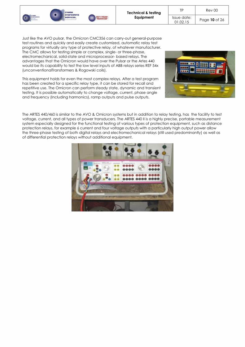
Just like the AVO pulsar, the Omicron CMC356 can carry-out general-purpose
test routines and quickly and easily create customized, automatic relay test
programs for virtually any type of protective relay, of whatever manufacturer.
The CMC allows for testing simple or complex, single- or three-phase,
electromechanical, solid-state and microprocessor- based relays. The
advantages that the Omicron would have over the Pulsar or the Artes 440
would be its capability to test the low level inputs of ABB relays series REF 54x
(unconventionalTransformers & Rogowski coils).
This equipment holds for even the most complex relays. After a test program
has been created for a specific relay type, it can be stored for recall and
repetitive use. The Omicron can perform steady state, dynamic and transient
testing. It is possible automatically to change voltage, current, phase angle
and frequency (Including harmonics), ramp outputs and pulse outputs.
The ARTES 440/460 is similar to the AVO & Omicron systems but in addition to relay testing, has the facility to test
voltage, current, and all types of power transducers. The ARTES 440 II is a highly precise, portable measurement
system especially designed for the functional testing of various types of protection equipment, such as distance
protection relays, for example 6 current and four voltage outputs with a particularly high output power allow
the three-phase testing of both digital relays and electromechanical relays (still used predominantly) as well as
of differential protection relays without additional equipment.

Technical & testing
Equipment
TP Rev 00
Issue date:
01.02.15 Page 11 of 26
A.C & D.C. High Voltage Testing International standards specify that all electrical distribution equipment be tested before connection to the
supply system. To meet this requirement, O'Hara Engineering Services Ltd uses a variety of equipment.
D.C. High Voltage Testing
The Biddle 160Kv D.C. Test Set provides a portable High Voltage source for
testing Cable, Switchgear, Insulators, Capacitors, and Transformers etc. The
Unit is suitable for Proof Testing, Step Voltage Testing and, as the unit has
micro ampere sensitivity, to test Insulation Resistance.
The Biccotest 60 kV DC test set T109 can be used to give 60 kV core-to-core.
A.C. High Voltage Testing
30 kV Power Frequency Test Set is a high powered, high voltage AC test
system designed for insulation testing. This system is equally suited to both
development and routine testing of electrical insulation systems and plant.
110 kV Power Frequency Test Set is a high voltage AC test system designed for
insulation testing. This system is suitable for routine testing of electrical Medium
and High voltage Switchgear and Plant, where high A.C. test voltages are
required.

Technical & testing
Equipment
TP Rev 00
Issue date:
01.02.15 Page 12 of 26
Instrument Transformer Testing & Maintenance Instrument transformers for protection purposes supply protection relays and must also function accurately at a
multiple of the nominal current. A regular inspection should ensure that instrument transformers, together with
the connected relays, react quickly and correctly in the event of a fault and guarantee the highest possible
security of supply. The importance of transformer tests is often underestimated. Risks such as confusing
instrument transformers for metering and protection, or mixing up connections can be reduced significantly by
testing before initial use. At the same time, damages to the interior of an instrument transformer, caused for
example during shipping, can be recognized easily. Also changes in an instrument transformer, caused for
example by aging insulation, can be identified at an early stage.
Current Transformer Analysis
O’Hara Engineering OMICRON’s CT Analyzer is a unique lightweight instrument designed to meet the highest
standards for performing excitation, ratio, polarity and winding resistance tests on current transformers (CTs) as
well as burden-impedance measurement as well as for testing protection transformers, including those with
transient behavior. It can also be used to calibrate instrument transformers due to its high level of accuracy. You
can test all essential parameters (ALF/FS, dimensioning factor Ktd, knee point VB) within minutes with just one
test cycle.
OMICRON’s CT Analyzer
Voltage Transformer Turns Ratio
Transformer Turns Ratio is the ratio of the number of turns in the high voltage winding to that in the low voltage
winding. An Instrument transformer turns ratio test set can directly measure the ratio of single phase instrument
transformers. Transformer ratio can change due to several factors, including physical damage from faults,
deteriorating insulation, contamination and hipping damage. If a transformer ratio deviates more than 0.5
percent from the rated voltage ratio, it may not operate reliably. To measure small ratio changes such as this,
the accuracy of the test equipment is of the highest importance.
TTR 100 Hand Held Turns Ratio Meter

Technical & testing
Equipment
TP Rev 00
Issue date:
01.02.15 Page 13 of 26
Sulphur Hexafluoride Testing
With the vast majority of switchgear manufacturers using air or Sulphur Hexifloride (SF6) as their insulating
medium in both the bus-bar chambers and circuit breakers it is of the upmost importance to note and record
the degradation of the insulating medium for various reasons. One very important reason is that SF6 whilst it is an
excellent insulating medium can extremely damaging to the environment and the health of the people
surrounding it’s use. SF6 pressure is recorded at switchgear commissioning time so that should there be an
abnormal level of gas released between FAT testing and the completion site it can be noted investigated and
corrected prior to handover. It is also important that the quality of gas is recorded so that the insulating medium
is up to the levels required by the switchgear design.
The EiUK – PGS40 is a test calibration pump used to generate pressure and a vacuum for checking, adjusting
and calibrating mechanical & electrical instrument by way of comparative measurements.
The Visala DM70 is designed to sample and test the dew point of SF6 Gas.
The device has many capabilities and offers a fast response time measurement result in less than 10 minutes.
Measurements are made on site via the various attachments. There are also various measurement parameters –
Td (Dew-point Temperature), Td calculated from gas pressure to atmospheric pressure, PPMw, & PPMv, &
Temperature, all of which can be logged and reported to PC.

Technical & testing
Equipment
TP Rev 00
Issue date:
01.02.15 Page 14 of 26
Partial Discharge Testing A partial discharge (PD) is an electrical discharge or spark that bridges a small portion of the insulation between
two conducting electrodes. Partial discharge can occur at any point in the insulation system, where the electric
field strength exceeds the breakdown strength of that portion of the insulating material. Partial discharge can
occur in voids within solid insulation, across the surface of insulating material due to contaminants or
irregularities, within gas bubbles in liquid insulation or around an electrode in gas (corona activity). Partial
Discharge activity provides clear evidence that an asset is deteriorating in a way that is likely to lead to failure.
The process of deterioration can propagate and develop, until the insulation is unable to withstand the
electrical stress, leading to flashover. The ultimate failure of HV/MV assets is often sudden and catastrophic,
producing major damage and network outages. We carry a range of equipment to enable our technicians to
identify installations where partial discharge is taking place.
The EA Technology Ultra TEV is the world's first combined ultrasonic and
transient earth voltage (TEV) hand-held detection instrument, capable of
detecting both surface and internal discharges in electrical switchgear from
3.3kV- 38kV. Our technicians can quickly scan for signs of partial discharge.
The Ultra TEV hand-held instrument combines ultrasonic sensors to pick up
early signs of surface discharge, with transient earth voltage (TEV) sensors to
detect internal discharges. The key to the Ultra TEV's accuracy is the threshold
levels to which the condition indicators have been set. These have been
derived by EA Technology from measurements of partial discharge taken in
6,000 substations and involving nearly 50, 000 switches.
The Mini TEV detects partial discharge, giving a reading of both decibel level
and pulse frequency. This allows a graded indication of discharge level.
Transient Earth Voltages(TEVs)
Measuring TEV emissions is a highly effective way of detecting, quantifying
and locating PD activity in live assets. The importance of TEV effects
(discharges of radio energy associated with PD activity) was first identified by
EA Technology in the 1970s EV sensors are employed in all of the above
instruments. This makes them far superior to products that only measure
ultrasonic emissions.
Ultrasonics
PD activity creates emissions in both the audible and ultrasonic ranges. The
latter is by far the most valuable for early detection and measurement. The
Ultra TVE and the Ultra TVE Plus employ ultrasonic sensors, in addition to TEV
sensors. Most importantly, the trigger points on instruments are precisely set to
indicate critical PD activity, which is immediately alerts to the user, regardless
of their level of expertise.

Technical & testing
Equipment
TP Rev 00
Issue date:
01.02.15 Page 15 of 26
Cable Identification and Fault Finding In the recent past it has become evident that fault location in power cabling by the "Thumping" method can
result in a much reduced cable life. It is now accepted that "Thumping" should be avoided if at all possible. In
order to overcome this, Time Domain Reflectometers have been developed suitable for locating faults on
power cables without the risk of damage to the cable under test.
The Fault Wizard system is based on automated arc-reflection technology
(AART) developed by IUP. The display shows the distance in feet or meters to
the fault location. The display also shows the fault type (open or short), the
battery voltage, the velocity of propagation setting, the charge voltage, and
whether the system is armed for waveform storage for retrieval and viewing
on a computer (desktop or laptop) by utilizing the Fault Wizard Software.
However, as stated before, viewing of the waveforms is not required since the
Fault Wizard gives an automatic readout of distance to the fault location.
Since the system is battery operated, it can be used in remote locations.
The Fault Wizard will locate faults up to 10,000 feet. The impulse voltage is
variable, which allows low-voltage pulsing and minimum damage to cables.
The system has a cycle mode for use in pinpointing the fault with a headset
listening device. However, the Fault Wizard has sufficient power to often be
felt and heard above ground.
We use Ridgid Seek Tech SR-20 for locating underground cables .This unit
differs from conventional Cat and Genny locators as the SeekTech provides
four distinct independent locate readings on the mapping display from 4
separate antenna to give confidence that the location is accurate. The
mapping display shows: Real time line direction and depth, directional
changes as they occur directional arrows that guide the user to the target
line and signal strength as well as a proximity number to get closer to the
target line. At the same time the user is receiving these visual indications, an
audible signal indicates if the user is right or left of the target line, and a
distinct audible signal indicates when the user is over the target.
The company can provide a cable identification and safety spiking service for all types of power cables.

Technical & testing
Equipment
TP Rev 00
Issue date:
01.02.15 Page 16 of 26
Battery Discharge Testing
Standby batteries must provide the equipment they serve with standby power in the event of a power failure.
However, the capacity of such batteries can drop significantly for a number of reasons before their calculated
life expectancy is reached. This is why it is important to check batteries at regular intervals. The only reliable way
of measuring battery capacity is to conduct a discharge test.
O’Hara Engineering use the Programma TORKEL for battery systems discharge testing ranging from 12 to 250 V.
Discharging can take place at up to 120 A, depending on battery voltage,. Tests can be conducted at
constant current, constant power, constant resistance or in accordance with a pre-selected load profile.

Technical & testing
Equipment
TP Rev 00
Issue date:
01.02.15 Page 17 of 26
General Testing
Standard Testing
We offer a complete range of standard tests required for compliance with ETCI rules, including:
Insulation resistance testing.
Continuity testing.
Earth Loop Impedance.
RCB testing.
Null balance.
Phase rotation.
Illumination levels.
Mains mapping.
Potable Appliance Testing
Structured Cable Testing
Our company has a full range of structured cable test equipment from mapping equipment, oscillators, to full
Cat 6 testing

Technical & testing
Equipment
TP Rev 00
Issue date:
01.02.15 Page 18 of 26
Training Course Currently there are two standards that apply to High Voltage Installations in his Country EN 50110-1-2014 &
EN61936 EN 50110-1 applies to all Voltages and it deals with the operation of Electrical Installations, EN61936 is a
conventional standard applying to voltages in excess of 1000 Volts AC and 1500 Volts DC. While EN50110-1
applies to all electrical installations it has its origins in “Safe Systems of Working” used by electrical utility
companies thought out the world for working on Distribution and Transmission systems.
This standard is applicable to all operation of and work activity on, with, or near electrical installations. These
installations operate at voltage levels from and including extra-low voltage up to and including high voltage.
This latter term includes those levels referred to as medium and extra-high voltage. This standard sets out the
requirements for the safe operation of and work activity on, with, or near electrical installations.
These requirements apply to operational, working and maintenance procedures. It applies to all electrical work
activities as well as non-electrical work activities such as building work near to overhead lines or underground
cables. This standard does not apply to ordinary persons when using installations and equipment, provided that
the installations and equipment are designed and installed for use by ordinary persons and they comply with
relevant standards.
The course covers the following topics and the procedures in relation to them:
Introduction
Intent and scope
Regulations.
Operation of Switchgear
Communication
Organizational Structure and Operational
Control Procedure
Documentation Generation
Switching Plans,
Disconnection for Work on Apparatus
Where to disconnect
Apparatus that can be made live from two
points
How to disconnect,
Checks on Disconnections,
Requests for disconnection
Proof of disconnection
Proof of Readiness
Verifications,
System Earthing
Hold off notices ,
Lock & Keys,
Definitions,
Live Working,
The course can be held in either your training centre or at our offices, and the costs remain same.
Class size is limited to a maximum of 6. The class duration is three full days. Only candidates with the relevant
experience should be considered for the course.
The Course is certified by O'Hara Engineering and is accredited by Engineers Ireland as a CPD course
ISO Certification All of our companies are now ISO accredited for Quality, Environmental Health & Safety.