Embed Size (px)
Citation preview

The engineer’s choice
tech.mag 01/2012
N E W I D E A S A T A G L A N C E

Dear customers, partners and friends of
ebm-papst,
The efficient use of energy and resources
is a declared global objective for the
decades ahead. In Europe, the first tier
of the ErP Directive is set to come into
effect at the start of 2013. In the USA,
standards have been laid down in
EEBA and ASHRAE and in China, effi-
ciency targets are defined in the
current five-year plan. The tasks
facing the research and develop -
ment depart ments of the ebm-papst
Group are thus clearly stated: com-
petitive products which are energy-
efficient in operation and resource-
saving in production.
Only the integrated consideration of
the efficiency chain from the motor
through the aerodynamics of the fan to
the optimal installation in the customer’s
appliance can lead to efficient operating
characteristics. Our GreenTech EC tech -
nology permits air performance to be called
up according to requirements using either
standard or customised interfaces. The special
motor drive guarantees high levels of running
smoothness at efficiencies of up to 90 percent. Our
use of composite materials for axial, diagonal and cen-
trifugal blowers with a diameter approaching one meter
is truly groundbreaking. Here, we have exploited the advan -
tage of design to innovatively increase efficiency by around
one third. At the same time, we have reduced noise emissions
by up to 6 dB. One example is our new RadiCal line of centri -
fugal fans. At this year’s Mostra Convegno and Chillventa exhi-
bitions, we will present a trendsetting innovation for axial
applications. We also offer our customers technically com -
petent support in the aerodynamic and acoustic optimisation
of their final applications, including in the use of our products.
With our GreenTech label, we confirm energy efficiency in ope-
ration. The efficiency of our EC products already exceeds the
stipulations of the second tier of the European ErP Directive
2015. The first step towards the resource-saving manu -
facturing of products has been taken with the start of series
production of the ESM fan, whose housing is made of a com -
posite material using renewable raw materials. We shall con -
tinue to systematically pursue this goal – independence from
conventional materials.
Offering the customer cost benefits in his assembly, no losses
due to efficiency and no increases in noise due to malad just -
ment of the motor-impeller-vent combination – that is what our
modu lar range offers. Practical electrical connections and
straightforward integration into the control system of the cus-
tomer’s application of interfaces that enable air performance
to be called up in accordance with what is actually required
make efficient operation possible. Moreover, more than 3000
indi vidual approvals in accordance with UL, CSA, CCC, GOST,
VDE as well as the standard CE Declaration of Conformity for
Europe permit our customers to use our products all around
the world. May I wish you many sustainable impressions when
reading this issue of tech.mag.
Dr. Bruno Lindl
Managing Director Research and Development
ebm-papst Group
“ebm-papst – innovativeand customer oriented”
2
Editorial

3
Efficiency in energy consumption, material usage, design and
installation: Development trends in fan technology
Cost savings through efficient components:
Energy-efficient centrifugal fans in fan coil units
Statistical failures for fans are being calculated differently: Laboratory
practices and computational theory for service life comparisons
Efficient GreenTech EC fans adapt to the application conditions:
Not just hot air
Page:
04 – 09
10 – 14
15 – 20
21 – 24
Content

Efficiency in energy consumption, material usage, design and installation:
4
Development trends in fan technology
© istockphoto.com

The much-used term of the day “efficiency”
describes the ratio of output to the input
needed to generate it. This is by no means
restricted to energy efficiency. In fan tech-
nology, the focus is certainly on maxi -
mum efficiency, not least in order to
satisfy the ever stricter future direc -
tives. Energy-efficient EC technology
is increasingly the technology of
choice. However, just as important in
fan development is material effi -
ciency. The buzzwords in this con -
text are bioplastics and material-
saving design elements that perform
several functions, reducing the total
number of components and manu-
facturing steps. Easy-to-install plug-
and-play solutions instead of many
individual parts also boost efficiency.
In practical use, they make it substan-
tially easier for the user to work with
the technology.
Fan efficiency has become a central issue
in ventilation and air-conditioning tech no -
logy. This is encouraged not only by the
statutory basis created with the Energy Conser-
vation Directive, but also by increased environ -
mental and cost awareness on the part of the user.
Against this background, it is no surprise that energy-
efficient EC technology is increasingly being employed in
all areas of application. And yet today, “asynchronous
motors” are still state of the art as fan drives in ventilation and
air-conditioning applications. And they are so because the tried
and tested AC motors are compact and straightforward in their
design as they are powered directly from the AC or three-
phase current supply. Neither mechanical collectors nor elec-
tronics are needed to power the rotor. They are robust and
reliable. However, EC motors achieve a much higher degree of
efficiency than AC motors, and this will be essential in the near
future with an eye on the requirements of the Energy Con -
servation Directive. That makes it important to allow the user
to change over to EC technology easily. The latest develop -
ments in ventilation technology reflect this.
Straightforward changeover to EC technology
For example, the motor and fan specialist ebm-papst
Mulfingen has developed a new generation of GreenTech EC
motors featuring integrated commutation and drive elec -
tronics, and which are just as compact as conventional AC
motors. On both axial and centrifugal fans, the original AC motors
can now simply be mechanically exchanged for a new EC
design (see figure 1). The exceptionally high efficiency of
GreenTech EC motors – up to 90 % – can be enjoyed without
having to make design modifications to the customer’s appli-
cation (see figure 2, page 6). Operating costs are reduced and
5
Figure 1: Despite the integrated commutation and drive electronics, the new GreenTechEC motors (right) are just as compact as conventional AC motors (left), making a simplemechanical exchange possible. (photo: ebm-papst)
“The new generation ofGreenTech EC motors are justas compact as conventionalAC motors”

Efficiency in energy consumption, material usage, design and installation:
Development trends in fan technology
the low energy consumption reduces the
impact on the environment. At the same time,
the drives impress with their quiet running,
which is especially beneficial for equip -
ment used in domestic appliances. The
key to this is an especially low-noise
com mutation which is precisely adap -
ted to the EC motor.
EC motors are by principle synchro-
nous motors actuated by permanent
magnets. The magnetic rotor syn-
chronously follows an electronically
generated rotating field. This allows
any random operating speeds to be
realised, regardless of the power
frequency used. However, this deve-
lopment represented a great tech -
nical challenge to accommodate the
electronics needed by GreenTech EC
motors in the limited space available.
Apart from the miniaturisation and opti-
misation of the electronics, mechanical
compatibility was also a necessity. This
includes, for example, modifying the com -
plete motor design in line with the AC motors
and adopting the mounting flange.
Optimisation potential in material usage and
manufacturing
When designing the new GreenTech EC motors, great
value was attached to sustainability and to resource-con-
serving manufacturing. There are several details that con -
tribute to this. The single-piece rotor with pressed-in shaft
reduced the number of manufacturing steps. Multifunction
components mean fewer individual parts are needed. Specific
heat elimi nation and comparably short bundles of laminations
in the motor help to reduce material. The smaller amount of
material used saves energy during manufacturing.
The sealing of the electronics also plays an important role here.
Instead of the flange solutions that used to be common,
featuring various O-rings, the electronics case has been given
an elastic sealing component. The housing flange comprises
two separate plastic components. The hard component (alumi-
nium) boosts stability, provides a receptacle for the motor and
helps to cool the motor, plus it also acts as a cover to protect
the integrated electronics. The soft, injection moulded
elastomer component provides for sealing compliant with IP55.
The terminal connector is already integrated. This reduces the
number of parts and at the same time guarantees long-term
protection for the electronics. The complete motor is robust,
insensitive to shock and impresses with its reliability and long
service life.
6
Figure 2: EC motors achieve efficiency of up to 90 %. (photo: ebm-papst)
Effic
ienc
y [%
]
Shaft power [W]
— EC motor— Three-phase asynchronous motor— AC capacitor motor— Shaded-pole motor
“GreenTech EC motors im -press with their quiet running”
Efficiency in energy consumption, material usage, design and installation:
Development trends in fan technology
Plastics and composite materials
There is also optimisation potential to be
exploited with respect to boosting the effi-
ciency of the fan blades. This relates firstly
to the fluid mechanics, and secondly to
the choice of materials. The large blades
made of steel or aluminium sheet or
die-cast aluminium that are most
commonly used for large axial fans
place narrow constraints on design
engineers. Naturally, the monolithic
blades with uniform plate thickness
limit design options. Moreover,
sheet steel has to be coated to
provide appropriate corrosion pro-
tection for outdoor applications. In
addition, costs for raw materials, in
particular for aluminium, are rising,
making a responsible and con ser -
vative use of raw material resources
necessary. Robust plastic materials
thus offer numerous benefits for fan
blades: While sheet metal parts can only
be punched, bent or stamped, it is easy to
create three-dimensional profiles with
plastics. Winglets, familiar from the aviation
field, can also be used here. These reduce
unwanted air flow between the circumferential
blade and housing. That improves efficiency and
noise behaviour. At the same time, the good damping
behaviour of the plastic helps to reduce noise and weight.
Depending on what is needed with respect to strength and
application, different materials can be used for the fan blades.
A typical example of this is the HyBlade® fan blade (see figure 3),
which substantially improves noise and efficiency on large
axial fans. Here, an aluminium inlet can withstand the
mechanical forces during operation and ensures a durable
connection to the rotor, while the plastic encapsulates the
carrier structure, giving the blade its optimised aerodynamic
shape.
Biomaterials reduce environmental impact
An equally important issue in fan development today is the use
of natural raw materials. For example, by 2015 ebm-papst will
have replaced 15 % of all the plastics it uses in its products
with sustainable materials. Work on this is progressing with
great success. The first “bio-fan”, on which the wall ring is made
of a wood/plastic composite, has already been built. Properties
such as durability and temperature stability are equally well
“By using plastic materials it is easy to createthree-dimensional profiles”
7
Figure 3: Basic structure of the HyBlade® blades: a carrier of high-strength, corrosion-resistant aluminium alloy is sprayed with a jacket of a special, fibreglass-reinforcedplastic. (photo: ebm-papst)

Efficiency in energy consumption, material usage, design and installation:
Development trends in fan technology
“The ‘bio-fan’ from Mulfingen started seriesproduction at the beginning of 2012”
8
fulfilled as compliance with all current technical specifications.
Corrosion is not a worry with this material combination and the
damping properties are exceptionally good. Among users, the
idea of biomaterials is met with a positive resonance and the
“bio-fan” from Mulfingen started series production at the be -
ginning of 2012 (see figure 4). In the future, other sus tainable
materials are sure to be used in fan technology.
System solutions not individual components
Extremely specific boosts in efficiency are realised by a
completely different development focus: complete system
solutions, plug-and-play appliances which, in contrast to
many individual components, are easy and practical to
install. One example of these are the EC mo -
tors described above, which are avai -
lable as complete solutions with
impellers and housings for
specific applications. The
user thus has a ready-to-
install fan solu tion (see
figure 5, page 9). Apart
from the installation
and logis tical benefits,
this also has substan -
tially bet ter efficiency
as all the individual com -
po nents are optimally con -
figured to one another (mo -
tor, electronics, impeller).
Multifunctionality for high flexibility
in assembly
A textbook example of a practical system
solution is the so-called filter fan. These
are well suited for economically dissipa ting heat loads from
switch cabinets or electronics enclosures. The patented
mechanical design of these specially developed diagonal fans
impresses with many details: their housing comprises two
multifunctional shells. In one half of the housing are the inlet
vents, guard grille and spacers for the filter mat. In the other
half is the rear guard grille and the motor support. Between
the two parts is the connector terminal with integrated wire
ducting. A bayonet coupling allows the fan and the filter
housing to be joined in four different positions. This allows a
different cable outlet positioned every 90 °. No extra tool is
needed for this. The same thing applies to changes in the
direction of air flow. Here, all the user has to do is to release
the bayonet coupling on the diagonal fan, turn
the fan unit through 180 ° and lock into
place again (see figure 6, page 9).
These examples show that
many different aspects
have to be taken into
account in modern pro-
duct development. Be -
sides energy efficiency,
which really ought to
be a matter of course
by now, material effi-
ciency and function play
key roles. At the same time,
it is increasingly impor tant to
design the best possible product
the user and his appli cation, and to
make a practical system solution avai -
lable, preferably a plug-and-play appli -
ance.
Figure 4: The fan with a “biomaterial” wall ring com-plies with all current technical specifications. (photo:ebm-papst)

Efficiency in energy consumption, material usage, design and installation:
Development trends in fan technology
Dipl.-Ing. (FH) Gunter Streng
Development Manager for Product Area A
ebm-papst Mulfingen GmbH & Co. KG
“The direction of air flow can be changedsimply by turning the fan unit”
9
Figure 5: Ready-to-install complete system in GreenTech EC technology. (photo: ebm-papst)
Figure 6: Mechanical details on the fan housing make assembly easier. For example, thedirection of air flow can be changed simply by turning the fan unit. No extra tools areneeded to do this (photo: Rittal)

Cost savings through efficient components:
10
Energy-efficient centrifugalfans in fan coil units
© Kampmann

Hear nothing. Feel nothing. See nothing. A good
climate control system is one that the guest
doesn’t even notice. It should work quietly
and without causing draughts. Its controls
should be self-explanatory and straight-
forward. Yet in practice it is often a diffe-
rent story. Even in high-class hotels
unacceptable climate control systems
are installed. And yet good air condi-
tioning is an important feel-good
factor for guests. And choosing the
right product can save you real
money!
Trouble-free and cost-effective ope-
ration is an important requirement
for a climate control system. Yet there
is often a droning sound behind the
panelling. This is no longer state of
the art. The climate control system
lives a lonely life. Nobody’s interested
in it so long as it’s working reasonably
well. The problem often starts with the
very installation. The investor or proprietor
of the hotel is responsible for procuring the
air conditioning equipment. But as a rule he
will only consider the procurement costs in his
calculation. Follow-up costs are irrelevant. That is
a problem for the operator. A dilemma!
Here, it is worthwhile for the hotel operator to insist in the
contract that he doesn’t have any “energy guzzlers” forced
upon him. The lion’s share of the costs do not come from pro-
curement, but rather from operation. Then there is the fact that
a climate control system is an important parameter for guest
satisfaction.
Important constituent components of a climate control system
are the fan coil units (see figure 1). Here, the motor and fan
manufacturer ebm-papst has developed a solution that sets
new standards with respect to cost efficiency. The broad
product range of nine different fan models has been conceived
to provide a model for all commonly used blower convectors
and for practically all room sizes. These new fans employ
GreenTech EC technology, are energy-efficient and quiet-
running. As a rule, upgrading will pay for itself within eighteen
months to two and a half years.
The right equipment will save you money
Rising energy costs and stricter legal regulations contribute to
the fact that the comprehensive consideration of buildings in
terms of their efficiency is playing an ever more important role.
Figure 1: Example of a fan coil unit (photo: GEA Air Treatment)
11
“A climate control system isan important parameter forguest satisfaction”

In particular in new buildings, but also in renovation work,
energy efficiency and “life cycle costs” (LCC) are increasingly
impor tant in the decision-making process when
choosing appli ances and components. High
energy savings potential can be
attained if the right technology is
used in ventilation and air-con-
ditioning techno logy, such as
climate con trol sys tems,
where the fans run almost
around the clock.
Fan coil units are part of
a central air conditioning
sys tem and have the task of
cooling or heating the air
using the air-recirculation pro ce -
dure. They belong to the group of
air-to-water air conditioning units, and
their principle function is easy to under-
stand. Depending on requirements, hea -
ted or cold water flows through the built-in heat exchanger.
Using the fan, air is guided past the heat exchanger, which
provides heating or cooling of the room air (see figure 2). Fan
coils are usually located close to where people are. That means
strict requirements with respect to comfort. Low-noise perfor-
mance across the entire operating range is a key criterion in
decision making. Today, this is achieved using intelligently
arranged and aerodynamically optimised fans. ebm-papst has
developed different types of quiet and energy-efficient fans for
fan coil applications. These fans in GreenTech EC technology
deliver air volumes up to 2,200 m³/h in the power range
between 40 and 250 watts (see figure 3a + b). All versions are
specially designed for low-noise operation. They are very
compact and are easy to install as a plug-and-play solution.
The fan is mounted on the exhaust flange and connected using
a plug system. The plastic materials used are light, yet
durable and sound absorbent.
No vibrations – quiet operation
Besides the noise of the air, the
noise generated by the motor
plays an important role,
especially at low speeds
(partial-load range), i. e.
with smaller air volumes.
For this reason, it is essen -
tial for this component to be
optimised. This is done by
enhancing the decoupling of
the motor and housing, or better
still with a sophisticated motor con -
cept which eliminates vibrations by its
very principle, preventing it from exciting
vibrations in its immediate surrounds.
Cost savings through efficient components:
Energy-efficient centrifugal fans in fan coil units
“Fan coils from ebm-papst: low-noise, compact and easy to install as a plug-and-play solution”
12
Figure 3a: Energy-efficient GreenTech EC fans for usein fan coils (photo: ebm-papst)
Figure 2: Using the fan, air is guided past the heat exchanger, which provides heating orcooling of the room air. (photo: Fa. Chiller)

Cost savings through efficient components:
Energy-efficient centrifugal fans in fan coil units
Motors with this property include, for example,
so-called EC motors (EC stands for “electro-
nically commutated”). In principle, EC motors
run synchronously, have no slip and so no
slip loss – an advantage over con ven -
tional asynchronous motor systems
with voltage or frequency control.
Asynchronous motors driven by a fre-
quency inverter, particularly under
partial load, produce resonance
noise that results in the typical
unpleasant motor hum.
Because EC motors also work with
great efficiency, they also consume
substantially less energy than con-
ventional AC drives. These potential
energy savings are not only realised
when the motor is operated under full
load, but also primarily when it is ope-
rated under a partial load, i. e. when the
speed is controlled accor ding to current
temperature requirements. EC motors then
lose far less efficiency than asynchronous
motors with the same output. The payback
period for the fans with more efficient drive
can be easily calculated by making a
comparison between EC and AC fans running at
the same operating point, with an assumed
operating time of 5000 h/a and energy costs of
0.15 euro/kWh for a period of 10 years. The graph in
Figure 4 illustrates the total (accumulated) operating costs of
an AC fan (red line) running with a standard speed control.
The intersection of the two lines shows when the GreenTech
EC solution (green line) has paid for its own procurement.
Ideal for renovations
Efficient centrifugal fans from ebm-papst in fan coil units
provide for greater comfort by controlling the air volume
precisely according to requirements. They work very quietly,
especially at low speeds, and make substantial energy savings
with the high efficiency of the EC motor. Even for existing
installations, fans that are already installed can easily be
exchanged for new energy saving GreenTech EC fans due to
the simple plug-and-play solution. So state-of-the-art tech -
13
Figure 3b: Energy-efficient GreenTech EC fans for use in fan coils (photo: ebm-papst)
Figure 4: Accumulated cost development – “pay-off“ time (photo: ebm-papst)
€
year
“The GreenTech EC solutionpays off after a short time”
— AC fan— EC fan
Cost savings through efficient components:
Energy-efficient centrifugal fans in fan coil units
14
nology proves once more to be simply the better choice – in
terms of energy savings as well as for comfort.
Further information under www.hotel.ebmpapst.com
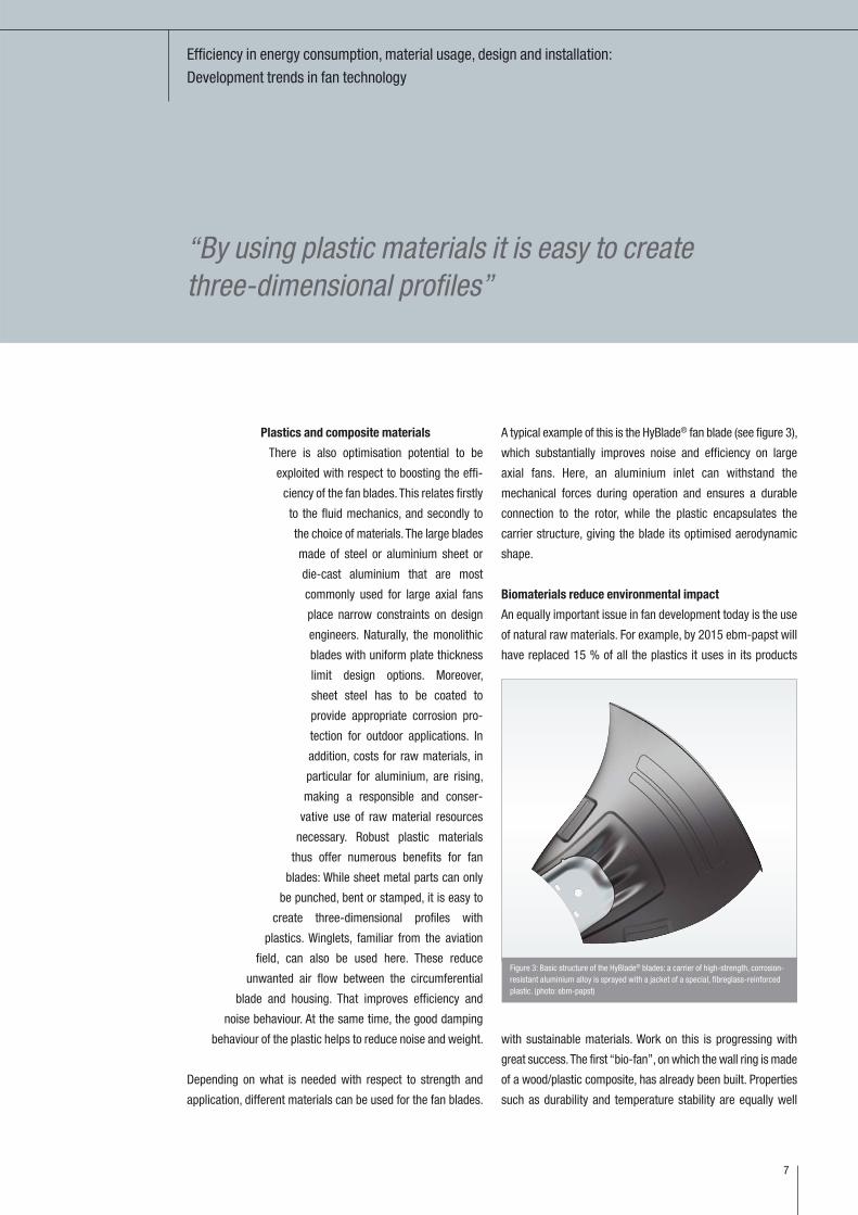
Dipl.-Ing. (FH) Uwe Sigloch
Head of Market Management,
Ventilation and Air-Conditioning Technology
ebm-papst Mulfingen GmbH & Co. KG

Statistical failures for fans are being calculated differently:
15
Laboratory practices and computational theory for service life comparisons
© fotolia

Service life is one of the most important cha-
racteristics for a product. This is particularly
true for electromechanical components like
fans. However, the manufacturers of such
devices use very different specifications
for specific numeric values for service
life. Even if the same terminology is
used, one statement is not necessarily
comparable with another depending
on the calculation techniques that
are used.
For long-lasting products such as
fans for cooling electronic compo-
nents (see figure 1), a realistic eva-
luation of service life of those elec-
tromechanical components is an
im portant deciding factor for users.
However, manufacturers cannot test
for decades before the customer re -
ceives the product. This is why the fan
specialists from ebm-papst St. Georgen
in Germany’s Black Forest region rely on
combining a theo-
retical approach,
where empirical
val ues have a
large influence,
and prac tical
val ues measured
in its own endurance
test laboratory. Other
manu facturers use different com-
putational and test procedures.
Since the results are not directly comparable, such specifi -
cations must be evaluated properly. Also it must be known
what statements are really hidden behind the numeric values.
Test practices in the laboratory
A theory is only worthwhile if its predictions are confirmed in
real-world applications. For this reason, a test lab is an
important support for the entire computational concept. In the
Black Forest test lab (see figure 2, page 17), the respective test
proce dures and cycles for various applications are run in dust
and salt spray chambers by Weiss Umwelttechnik; environ -
mental tests are carried out in temperature and climate-
controlled cabinets made by Vötsch and CTS. In addition, there
are also test cabinets and a temperature chamber for normal
long-term tests under thermal load and equipment for vibra -
tion tests. Tests that at first glance appear extreme for fans,
like the salt spray test, are important for example to reliably
predict the service life in applications such as tele communi -
cations on a sea coast (e. g. transmission module cooling).
Heat tests emulate use in deserts or very warm industrial
environments. A test for temperature durability goes through
a pre-defined number of hours in cold and hot profiles, which
were also defined in advance. Without failing, a fan also
needs to be able to cope with days of intense solar
radiation and nights with cold equalizing winds
with nega tive tempe ra -
tures. For the ther mal
shock resis tance test,
Statistical failures for fans are being calculated differently:
Laboratory practices and computational theory for service life comparisons
“A test lab is an importantsupport for the entire com-putational concept”
16
Figure 1: A wide range of centrifugal and axial fans fulfil highest requirements – also regarding service life. (photo: ebm-papst)

a specific drive, for example, must prove its
endurance by passing the tests including
electrical function testing in increments of
5 °C from -40 °C to +120 °C. Depending
on the application, it may be very hot and
splashes of water can cause abrupt
cooling. This is simulated by a tempe-
rature shock induced with a gush of
water. The drive is heated to 110 °C
and cooled with a gush of water at
0 °C in 3 seconds. This is repeated
approximately one hundred times.
Afterwards, the housing, seals and
function must all conform to require -
ments.
Meaningful results
Long-term fatigue tests last many
years. The so-called “marathon fans”
are test specimens, a portion of which
have been running in a temperature
cabinet since the early 80s, interrupted
only by being moved. The data extracted
from more than 30 years of continuous
operation are combined with data from other
tests for the current life span calculations. The
independent Austrian Centre of Competence for
Tribology (AC²T) also examined some of the conti-
nuously operating units that are still working. A type
7650 fan with a 201,900 h run-time (23 years) and a
4850 N fan (figure 3a, 3b) with 170,500 h (19.5 years)
were examined, each of which ran at 40 °C. An 8412-GL
example with 125,600 h (14.3 years) at 70 °C was also
included. The analysis findings confirmed the in-house service
life evaluation. Together with the influences from new manu -
facturing processes, new materials and lubricants as well as
Statistical failures for fans are being calculated differently:
Laboratory practices and computational theory for service life comparisons
“Drives are tested in long-term fatigue tests – someare running almost 30 years in continuous operation”
17
Figure 3a, b: Almost 20 years of continuous operation and no measurable wear, 3a (top)sleeve bearing in a cross-section and 3b (bottom) fan impeller shaft (photo: ebm-papst)
Figure 2: Test candidates in the test lab; they undergo the endurance test at 40 °C and70 °C until they break down. (photo: ebm-papst)

other components, a complete concept results,
which replicates actual conditions during a
fan’s lifetime with exacting precision.
Theory needs practical relevance
Service life and reliability (see text box,
page 20) are two common values, which
in general cannot be converted into
each other. The reason for this is the
weighting of classic failure perfor-
mance for components. This perfor-
mance means that a relatively large
number of components could fail at
the start due to faulty parts or instal-
lation errors. This part of the failure
probability can be reduced dras -
tically by testing and “burning in”
(test running) the new parts before
delivery. In the subsequent period, the
devices that pass the test endure long
operating times with only a few, ran -
dom failures. Towards the end of service
life, wear then becomes noticeable and
the failure rate increases again. This failure
rate can be shown quite well graphically
using a so-called Weibull evaluation and a
bath tub curve (see figure 4). The steep drop-off
of the early failure rate is followed by the long,
stable phase of random failures, which slowly tran-
sitions to the steeply increasing phase of wear-related
failures towards the end. Additional influences such as in -
creased temperature, vibration or shock and chemical reac -
tions (cleaning agents or disinfectants, dust, salt, dust, steam,
etc.) influence the failure rate and the shape of the curve as well.
In order to limit the testing period, often a larger number of
devices are operated for a short time (typically 6 months to a
year). Then the service life is extrapolated from the result using
different methods. However, this result provides incorrect
Statistical failures for fans are being calculated differently:
Laboratory practices and computational theory for service life comparisons
“External influences can heavily impact the service life of devices”
18
Figure 4: The bathtub curve (bottom) and Weibull evaluation (top) provide a quick over-view of service life and reliability. (photo: ebm-papst)
Failu
re p
roba
bilit
y F
(t) /
%
Service life t/h
Grad
ient
b
L10 from test with wear
L10 from test without wear
Random failure Wear
Failu
re ra
te �
(t)
Operating time t
Error typePremature
failure Random failureWear failure

Statistical failures for fans are being calculated differently:
Laboratory practices and computational theory for service life comparisons
results for fans, since service life can be deter-
mined only if the test already includes cases
of wear as well. Otherwise, the values for
failure will normally be too high and the
service life information that is obtained is
too optimistic.
Since external influences heavily
impact service life, these can be used
to generate premature ageing, for
example by running tests with in -
creased temperatures or tempe ra -
ture changes or temperature shocks.
This shortens the actual testing
period drastically. The disadvantage
of such an approach compared to an
actual long-term fatigue test is the
effects of the temperature influ -
ence – which are often impossible to
measure realistically – and retroactive
projection of that influence to normal
operating temperatures. Thus, a tem -
perature drop of 10 to 15 Kelvin is
assumed to result in a doubling of service
life for many computational models. If this
“extrapolation” is applied multiple times (e. g.
with a test at 70 °C or higher and specifications
of service life at less than 40 °C), then unrealistic
service life values approaching absurdity will soon
result. Despite similar results in an accelerated service
life test, the service life information of various manu -
facturers can differ by a large factor. Thus, a conservative
estimate of all influencing factors is essential for realistic spe-
cifications. However, long-term experience and constantly
opti mised arithmetic operations are absolutely necessary for
such practical evaluations (see figure 5).
The Black Forest region fan experts take these variations into
account during evaluation by providing three different specifi-
cations for service life in the catalogue. The first two values
are related to an in-house measuring standard, which is im -
proved constantly by intensive, long-term service life tests in
ebm-papst’s own test lab. For this, the test fans are operated
at various temperatures until they fail. Thus, demonstrable
service life values for both L10 (40 °C) and L10 (Tmax, usually
70 °C) result, which very closely reflect failure performance in
real-world applications. In order to offer the user a simpler
“Long-term experience are absolutely necessary for such practical evaluations”
19
Figure 5: Influence of acceleration factors used by various manufacturers on the calcu-lated expected service life (photo: ebm-papst)
Life
exp
ecta
ncy
Operating temperature (°C)
1.65/10 K
1.5/10 K
2/10 K
L10� = 2/15 K
ebm-papst standard
Statistical failures for fans are being calculated differently:
Laboratory practices and computational theory for service life comparisons
comparison, a third value is used: expected service life. This
value, identified as L10Δ, is based on the calculation methods
frequently used throughout the fan market in general.
Fundamental data supported by statistical evaluation must be
verified continuously through long-term tests. Manufacturers
with traceable testing operations, which have accompanied
production for years, can gain an advantage by providing
realistic values. In this case, even individual tests for stringent
requirements under the assumed conditions are often not a
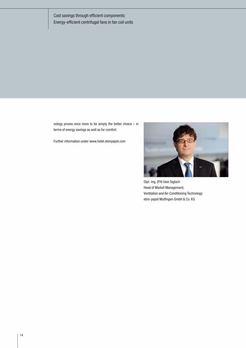
problem. Dr. Lutz Ramonat
Bearing Technology and Reliability,
Central Research and Development
ebm-papst St. Georgen GmbH & Co. KG
20
Service life or reliability
Service life and reliability are two terms that are often used
and equally easy to mix up. Service life, often abbreviated to
L10, specifies a period in hours during which up to 10
percent of the devices will have failed. A L10 of 100,000 h,
for example, means that 90 % of tested devices have
reached this run-time. In contrast, reliability is specified
with the value Mean Time Between Failure (MTBF). Since
fans normally cannot be repaired, a more apt designation
would actually be MTTF (Mean Time To Failure). Despite
this, MTBF has become the expression that is most
commonly used. Statements regarding MTBF values only
apply during the planned period of validity (e. g. usable
service life). The failure rate can increase significantly after
that due to signs of wear. A MTBF value of 1,000,000 h
(more than 110 years) means that if 1,000 devices were
running at the same time, one of them would fail every
thousand hours, i. e. every 42 days (1000 h * 1,000 =
1,000,000 h).

Efficient GreenTech EC fans adapt to the application conditions:
21
Not just hot air
© Kollektorfabrik

Efficient GreenTech EC fans adapt to the application conditions:
Not just hot air
Today, solar air collectors working with vacuum
tubes are a particularly practical solution
when it comes to the efficient exploitation
of solar energy. Their basic structure is
comparable to a thermos flask filled with
air. In contrast to conventional systems
which use liquids to collect and trans -
fer the heat, air does not freeze, it is
available everywhere, and it cannot
leak out, causing damage to the col-
lector circuit or the building. For
domestic hot water and central hea-
ting support employing vacuum
tube solar air collectors, a fan draws
the heated air through a heat ex -
changer. The design of the centri -
fugal fans has been modified to take
account of the fact that the instal -
lation space required for this appli -
cation is somewhat tight on account of
the design of the collectors, plus the
fact that site of operation can be ex -
posed to very high temperatures, depen -
ding on the amount of solar radiation it
receives and on the heating requirements of
the system. That allowed innovative GreenTech
EC technology to be integrated, guaran teeing an
energy-efficient and quiet operation of the appli-
cation.
Kollektorfabrik GmbH & Co. KG, based in March-Buch -
heim, Germany, does not employ liquids as the heat transfer
medium in its “Sun-Storm” range of solar air collec tors, but
rather air in its vacuum tubes. Such a vacuum tube (see figure 1)
consists of two glass tube, one inside the other and joined at
one end. At the other end, the tubes are closed. Between the
tube is a vacuum. This design has numerous benefits for the
application.
The vacuum tube and its benefits
The good insulating properties of the vacuum allows the solar
collector to work with great efficiency, as very little heat is
emitted to the surroundings. The vacuum tube is easy to touch.
Its outside temperature is a pleasant 45 °C, even though the
interior temperature can be as hot as about 230 °C. This
property is especially beneficial in the winter. At very low
ambient temperatures, the good insulation allows tempera -
tures of over 100 °C to be reached inside the “Sun-Storm”
collector. Cold air is introduced through a thin aluminium
injector pipe. This is heated up on the absorber surfaces inside
the “thermos flask”. That guarantees reliable and highly effi -
cient heat transfer. This is beneficial in many different
applications, e. g. in processes that directly require warm air.
These include for example air pre-heaters in controlled
ventilation systems, air heating, for example in industrial halls,
22
Figure 1: Structure of a vacuum tube (photo: Kollektorfabrik)
Direct solar radiation
Diffuse radiation
Thermal losses
Double-walledglass vacuumtube
Absorber
Injection tube
“GreenTech EC technologyguarantees an energy-efficientand quiet operation”

Efficient GreenTech EC fans adapt to the application conditions:
Not just hot air
sports halls, leisure parks, hot air generation for saunas or
paintshops, and numerous industrial drying processes and
solar cooling systems with open ventilation circuits.
The “Sun-Storm” collector can also be coupled to an air/water
heat exchanger to heat up fluids to over 120 °C (see figure 2),
making it eminently suitable for domestic hot water heating
systems with central heating support. The fact that the “Sun-
Storm” collector is recognised as eligible for subsidies in many
different schemes such as the “Renewable Energies” program
of the KfW and for the market incentive program of the BAFA is
a further argument for its use. Different variants with different
dimensions ranging from 9 to 30 m² and the option of com -
bining several systems together to create a total area excee -
ding 1000 m² mean that the collectors are equally suitable for
detached houses and multi-family homes (see figure 3) as they
are for schools, office buildings, swimming pools, fuel stations,
sports halls and industrial halls, to name just a few.
Tailor-made fan for the heat exchanger box
To ensure that the heat exchanger and fan harmoniously fit into
the design of the vacuum tube solar air collectors, the Sun-
Storm design engineers have developed a so-called liquid-air
box (see figure 4), which despite its compact dimensions
accommodates both heat exchanger and fan. This places
“The Sun-Storm collector is suitable for domestic hotwater heating systems with central heating support”
23
Figure 2: Schematic illustration of a domestic hot water system with central heatingsupport (photo: Kollektorfabrik)
Figure 3: Sun-Storm collector on the flat roof of a single-family home (photo: Kollektorfabrik)
Figure 4: The liquid air box (viewed from the rear) with heat exchanger and fan impres-ses with its compact dimensions. (photo: Kollektorfabrik)
Collector
Sola
r circ
uit
retu
rn fl
ow
Liquid air box
Sola
r circ
uit
inle
t flo
w
SystemTap water heating, Heating support

Efficient GreenTech EC fans adapt to the application conditions:
Not just hot air
special demands above all on the fan. These could only be
resolved with a specially modified design. Not only were com -
pact dimensions required. The electronics of the GreenTech EC
fans also had to be protected against the high temperatures
encountered at the heat exchanger.
Not least for that reason was a centrifugal fan from the motor
and fan specialist ebm-papst selected. As a pioneer in the field
of modern GreenTech EC technology, the engineers from Mul-
fingen have the necessary expertise for customer-specific
solutions that can be integrated into just about every appli -
cation. For the liquid-air box application, the impeller was not
mounted directly on the rotor in the usual manner, but rather
on the extended shaft (see figure 5). This protects the motor
against the high temperatures encountered inside the box.
That enables the benefits of energy-efficient EC tech nology to
be used in this application
Energy efficiency and intelligence
In contrast to AC technology, an EC motor is used to drive the
EC fan. This is equipped with an electronic control device, the
so-called commutation electronics. In prin ciple,
these motors run synchro nously, have
no slip and so no slip loss – an
advantage over conventional
asynchronous motor systems
with voltage or frequency con-
trol. Because EC motors also
work with great effi ciency, they also
consume sub stantially less energy than
con ven tional AC drives. These potential
energy savings are not only realised
when the motor is operated under full
load, but also primarily when it is ope-
rated under a partial load, i. e. when the speed is controlled
according to current heat require ments. EC motors then lose far
less efficiency than asynchronous motors with the same output.
Simple to control and quiet in operation
The EC motors that power fans feature an integrated electronic
control system that allows the speed of the fan to be adapted
precisely to what is actually required. In the application des -
cribed, actuation for requirement-orientated operation is rea -
lised with either an analogue 0...10 V signal or a PWM signal.
The fact that the motors can thus work hand in hand with all
the other standard control systems that are normally found in
solar technology is also appreciated by the “Sun-Storm” col-
lectors. To allow the motor and fan to be monitored, an
additional pulse is emitted every revolution at the tach output.
Also extremely important in association with solar collectors is
noise development, as the units are installed directly on the
roof. Residents and neighbours are not to suffer from noise
disturbance. Not in the house, nor on the patio or balcony. Here
too, EC drives are the better choice, be cause the motors pro -
duce practically no noise (see figure 6, page 25). In con trast,
asynchronous motors driven by a fre quency in -
verter, parti cu larly under partial load, pro -
duce reso nance noise that results in
the typical un pleasant motor hum.
This would cer tainly not pro -
vide a pleasant living envi-
ronment. Users of the
solar collectors have
nothing to fear
here. The solar sys -
tems equipped with
GreenTech EC fans
24
Figure 5: Innovative GreenTech EC technology adapts itself to the application. On thiscentrifugal fan, the impeller is not mounted directly on the rotor in the usual manner, butrather on the extended shaft. (photo: ebm-papst)
“The engineers from ebm-papst have the necessaryexpertise for customer-specific solutions”

Efficient GreenTech EC fans adapt to the application conditions:
Not just hot air
are pleasantly quiet in their operation, producing practically no
noise either in the house or on the patio or balcony.
Dipl.-Ing. (FH) Andreas Salig
Project Engineer in Sales, Germany
ebm-papst Mulfingen GmbH & Co. KG
25
Figure 6: GreenTech EC fans also score with respect to noise development. They aremuch quieter than AC solutions with the same output. (photo: ebm-papst)
Legend:— ebm-papst EC control— Frequency inverter with sine filter— Phase-angle control without sine filter— Phase-angle control with sine filter— Transformer

26

27

ebm-papst
Mulfingen GmbH & Co. KG
Bachmühle 2
D-74673 Mulfingen
Phone +49 (0) 7938 / 81-0
Fax +49 (0) 7938 / 81-110
www.ebmpapst.com
Art.-Nr. 40034-7-8811- SC-04/12-2,0’
Printed in Germany
ebm-papst
St. Georgen GmbH & Co. KG
Hermann-Papst-Straße1
D-78112 St. Georgen
Phone +49 (0) 7724-81-0
Fax +49 (0) 7724-81-1309
ebm-papst
Landshut GmbH
Hofmark-Aich-Straße 25
D-84030 Landshut
Phone +49 (0) 871-707-0
Fax +49 (0) 871-707-465


![DESIGN VERIFICATION TEST REPORT...3.15 . Comparison Push vs. Pull ebm-papst 412H 3.16 Résumé ebm-papst 412 ebm-papst 412H Pull cooling Push cooling Pull cooling Push cooling [m³/h]](https://img.dokumen.tips/doc/110x75/5f0989a47e708231d4274d86/design-verification-test-report-315-comparison-push-vs-pull-ebm-papst-412h.jpg)