Embed Size (px)
Citation preview

THIS GUIDE AND TECHNOTE APPLY ONLY TO STYROFOAM BRAND XPS.MEASUREMENTS, PERFORMANCE AND DATA NOTED USED , DOES NOT APPLY TO ANY OTHER BRAND INSULATION.
Tech Solutions 508.3 Ballast Design Guide for PMR Systems
Installation Information
INTRODUCTION
This document has been developed for those who design, specify, or install protected membrane roof (PMR) systems to assist in the selection of job-specific stone and/or paver ballast design. PMR assemblies place DuPont™ Styrofoam™ Brand Extruded Polystyrene Insulation above the roofing membrane, protecting it from UV degradation, physical abuse, freeze-thaw cycling and the stress of temperature extremes. The application of roof ballast in accordance with this guide will protect the underlying filter fabric and insulation from displacement during wind and rain storms. PMR systems should be installed in accordance with the recommendations of this guide, those of DuPont’s Protected Membrane Roofing Installation Guidelines and good roofing practice. The recommendations in this Guide have been derived from an extensive series of wind tunnel testing of ballasted roofing systems at the National Research Council of Canada and from relevant sections of ANSI/SPRI RP-4 “Wind Design Standard for Ballasted Singly-Ply Roofing Systems”. This document first presents some General Design Considerations, then a series of tables from which the proper ballast design can be selected. The final section describes the requirements and alternatives of four recommended ballast designs. It is the responsibility of the design professional, and/or installer to ensure that the PMR system is appropriately designed for each building.
General Design Considerations:The following factors should be considered when designing a ballasted PMR system:
Roof StructureThe building structure be appropriately designed to support all anticipated present and future loads on the roof.
SlopeThe roof slope shall not exceed 2-inch vertical rise per horizontal foot (2” in 12”)
Wind SpeedDetermination of the design wind speed for buildings in Canada should reference Figure 1 (km/h) or from the Authority Having Jurisdiction (AHJ). The 3-sec gust wind speed can be determined by applying a multiplying factor of 1.32 factor to the Figure 1 map speeds.
Determination of factored design wind speed for buildings in the USA will depend on the Exposure and Risk Category assigned to the project building and the version of ASCE-7 wind map selected by the designer or mandated by the AHJ. It is imperative that the designer confirm the factored design wind speed in order to determine the correct the ballast system. Figures 2 to 5 depict ASCE-7 Exposure C, Risk Categories I to IV Ultimate wind speeds for the USA and is shown for reference only. If the building is specified as Exposure B the designer must refer to the appropriate Exposure B ultimate design wind speed maps in ASCE 7-16. In any Risk or Exposue the map ultimate wind speeds need to be factored down by 0.774 to the working load.
Roof HeightA building may include numerous roof sections of different elevations. The height of each roof section is defined as the distance between ground level for that building section and the top of the ballast for that roof assembly.
Parapet HeightFor the purpose of determining the appropriate ballast design, the parapet height shall be defined as the distance from the top of the ballast to the top of the parapet. If the height varies, the shortest parapet height should be used. For special cases, contact your DuPont sales representative 1-866-583-2583.
Gravel StopIf a gravel stop is used at the building perimeter, its height above the ballast should be a minimum of 2” (50 mm) to contain the ballast.
Roof Areas Requiring Extra BallastRoof perimeters, corner areas, and large roof penetrations require additional ballast to reduce potential displacement of ballast and/or insulation during high wind loads or intense rainfalls. The weight and dimensions of those increased ballast zones are specific to the type of Ballast System recommended. Tables A and, B shall be used to determine the required Ballast System. The specifications for each Ballast System are outlined further in this document.

THIS GUIDE AND TECHNOTE APPLY ONLY TO STYROFOAM BRAND XPS.MEASUREMENTS, PERFORMANCE AND DATA NOTED USED , DOES NOT APPLY TO ANY OTHER BRAND INSULATION.
Building ExposureThe surrounding terrain has an effect on the overall wind exposure of the building. The exposure categories used for PMR systems are defined pursuant to ASCE-7 criteria; as either “B” or “C”. Buildings in a “B” exposure are typically in urban areas with numerous, closely spaced obstructions having the size of a single family dwelling or larger. Buildings in a “C” exposure are open terrain with scattered obstructions, including surface undulations or other irregularities, having heights generally less than 30 ft. This category includes flat open country, grasslands, and all water surfaces in hurricane prone regions.
Concrete PaversConcrete pavers shall be manufactured from minimum 3,000 psi (20 MPa) concrete and whose minimum weight shall be determined by the Requirements of PMR Ballast Designs listed further in this document.
Paver VentingIf paver ballast is to be used and will cover over 10 percent of the insulated area paver venting is needed. This can be provided with paver pedestals, a 1” (25mm) layer of clean pea gravel, rubber tabs, ribbed or footed concrete pavers, or top surface ribbed insulation. In locations with HDD (heating degree day) values less than 3000 ⁰F-days (1670 °C-days) paver venting is not required if the pavers are covering only a limited area, such as corners of the roof or narrow roof walkways.
Paver StrappingStrapping of pavers shall be accomplished with minimum 22 gauge, 3” wide x 12’ long galvanized or stainless steel straps. Strapping shall be mechanically fastened to each paver with minimum 1/4” x 1-1/4” corrosion-resistant metal anchors, installed in predrilled holes. Zamac Nailin #2814 by Powers Fasteners, Inc. and TRUFAST Zamac Nailin by TRUFAST Corporation or similar fasteners are acceptable.
Filter FabricStone ballast shall be installed over an approved filter fabric. Fabric prevents the migration of fine particles to the membrane level and prevent dislodgement of insulation boards in the event of roof flooding and floatation. The use of a filter fabric under paver ballast is not necessary.
Some acceptable fabrics include:
PGI - FABRENE VIE
AHI - Stone Filter Fabric
INT’L PAPER - CONFIL 689H
THRACE - GTF-200S
PHILLIPS FIBERS - RUFON P3B
For more information on filter fabrics contact the DuPont Contact Center at 866-583-2583 or your sales representative.
Controlled-Flow Drain Systems and Blue Roof (Water Retention) DesignsBlue Roof Systems and Control Flow Drain Roof Systems are roofing system designs that restrict the drainage of rainwater, slowing its release rate into sewer systems mitigating the impact of water runoff. Depending on the intensity of rainfall, roof slope, drain flow characteristics, insulation thickness and ballast weight, the insulation may float once a threshold depth of water above the membrane is reached. As a guide, Table 1 shows the ballast required to prevent the insulation from floating when the ballast is not submerged or is fully submerged. The latter results in loss in effective ballast because of water’s buoyancy effect on the submerged stone ballast. The recommended ballast takes this into account.
Caution: The additional load from heavy ballast and/or deep water retention over the roof structure needs to be taken into account at the structural design stage. Water retention roofs and control flow drain systems should be designed to allow evacuation of retained water within 48 hours of maximum accumulation.
TABLE 1: Ballast Requirement to Prevent Flotation
Insulation thickness inches (mm)
Ballast (non-submerged)
lb/ft2 (kg/m2)
Ballast (fully submerged)
lb/ft2 (kg/m2)
2.0 (50) 12 (49) 15 (74)
3.0 (75) 15 (74) 23 (110)
3.5 (90) 18 (86) 26 (129)
4.0 (100) 20 (98) 30 (147)
4.5 (115) 23 (110) 34 (165)
5.0 (125) 25 (123) 38 (184)
5.5 (140) 28 (135) 41 (202)
6.0 (150) 30 (147) 45 (221)
7.0 (175) 35 (172) 53 (257)
8.0 (200) 40 (196) 60 (294)
9.0 (225) 45 (221) 68 (331)
THIS GUIDE AND TECHNOTE APPLY ONLY TO STYROFOAM BRAND XPS.MEASUREMENTS, PERFORMANCE AND DATA NOTED USED , DOES NOT APPLY TO ANY OTHER BRAND INSULATION.
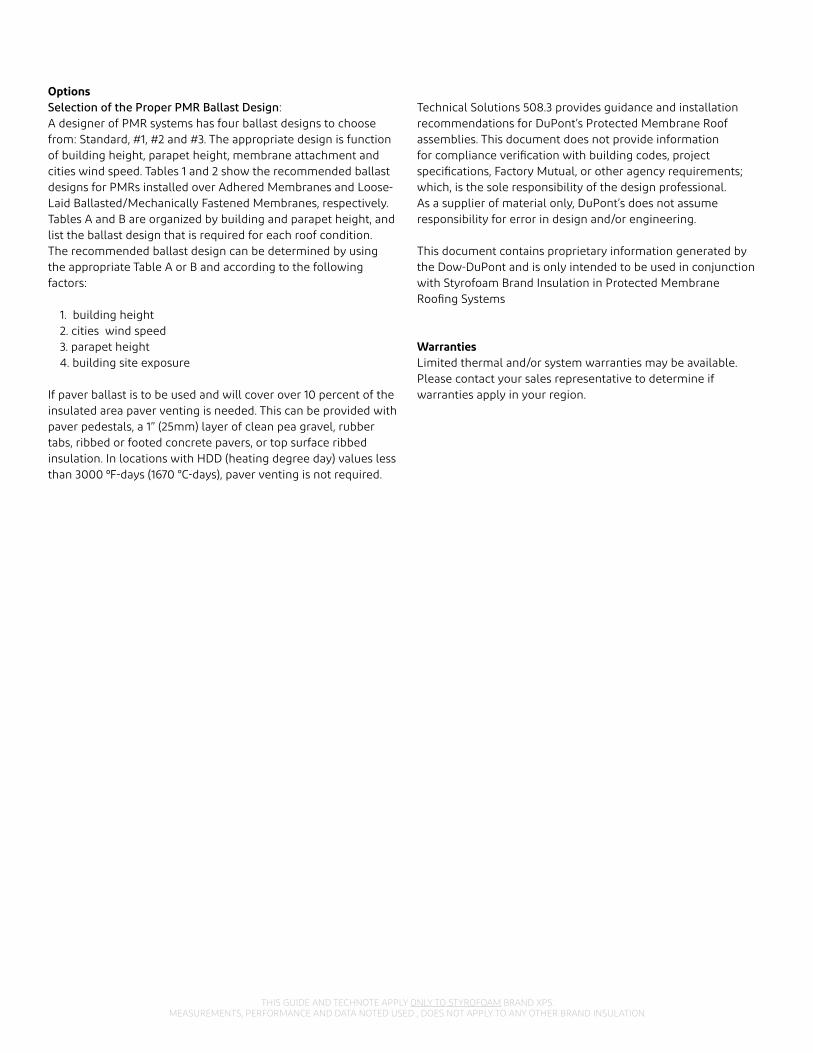
OptionsSelection of the Proper PMR Ballast Design:A designer of PMR systems has four ballast designs to choose from: Standard, #1, #2 and #3. The appropriate design is function of building height, parapet height, membrane attachment and cities wind speed. Tables 1 and 2 show the recommended ballast designs for PMRs installed over Adhered Membranes and Loose-Laid Ballasted/Mechanically Fastened Membranes, respectively. Tables A and B are organized by building and parapet height, and list the ballast design that is required for each roof condition. The recommended ballast design can be determined by using the appropriate Table A or B and according to the following factors:
1. building height2. cities wind speed3. parapet height4. building site exposure
If paver ballast is to be used and will cover over 10 percent of the insulated area paver venting is needed. This can be provided with paver pedestals, a 1” (25mm) layer of clean pea gravel, rubber tabs, ribbed or footed concrete pavers, or top surface ribbed insulation. In locations with HDD (heating degree day) values less than 3000 ⁰F-days (1670 °C-days), paver venting is not required.
Technical Solutions 508.3 provides guidance and installation recommendations for DuPont’s Protected Membrane Roof assemblies. This document does not provide information for compliance verification with building codes, project specifications, Factory Mutual, or other agency requirements; which, is the sole responsibility of the design professional. As a supplier of material only, DuPont’s does not assume responsibility for error in design and/or engineering.
This document contains proprietary information generated by the Dow-DuPont and is only intended to be used in conjunction with Styrofoam Brand Insulation in Protected Membrane Roofing Systems
WarrantiesLimited thermal and/or system warranties may be available. Please contact your sales representative to determine if warranties apply in your region.

THIS GUIDE AND TECHNOTE APPLY ONLY TO STYROFOAM BRAND XPS.MEASUREMENTS, PERFORMANCE AND DATA NOTED USED , DOES NOT APPLY TO ANY OTHER BRAND INSULATION.
Parapet heights 2” (.05m) gravel stops to 36” (0.90m) high parapets
Design Wind Speed (Figure 1 )Canada - Wind Speed on 50 yr. return period – 3-sec gust – km/h (m/s)
90 (40)
100 (45)
110 (49)
120 (54)
130 & 140 (58 & 63)
Design Wind Speed (Figures 2 to 5)USA Wind Speeds based on 700 yr. return period – 3-sec gust - mph (m/s)
115 (51)
130 (58)
140 63
155 (69)
270 & 290 (120 & 129)
Site Exposure C&B C&B C&B C&B C&B
Ballast design Standard 1 1 1 1
Parapet heights > 36” (0.9m)
Design Wind Speed (Figure 1)Canada - Wind Speed on 50 yr. return period – 3-sec gust – km/h (m/s)
90 (40)
100 (45)
110 (49)
120 (54)
130 & 140 (58 & 63)
Design Wind Speed (Figutres 2 to 5)USA Wind Speeds based on 700 yr. return period – 3-sec gust - mph (m/s)
115 (40)
130 (45)
140 (63)
155 (69)
270 & 290 (120 & 129)
Site Exposure C&B C&B C&B C&B C&B
Ballast design Standard Standard Standard Standard Standard
Table A: Ballast System for Adhered Membranes A1 – Roof Heights: 12’ (3.7m) to 45’ (13.7m)
Parapet heights 6” (.15m) gravel stops to 36” (0.90m) parapet heights
Design Wind Speed (Figure 1)Canada - Wind Speed on 50 yr. return period – 3-sec gust – km/h (m/s)
90 (40)
100 (45)
110 (49)
120 (54)
130 & 140 (58 & 63)
Design Wind Speed (Figures 2 to 5)Equivalent ASCE 7-10 Basic Wind Speeds based on 700 yr. return period – 3-sec gust - mph (m/s)
115 (51)
130 (58)
140 63
155 (69)
270 & 290 (120 & 129))
Site Exposure C&B C&B C&B C&B C&B
Ballast design Standard 1 1 1 1
Parapet heights > 36” (0.9m)
Design Wind Speed (Figure 1)Canada - Wind Speed on 50 yr. return period – 3-sec gust – km/h (m/s)
90 (40)
100 (45)
110 (49)
120 (54)
130 & 140 (58 & 63)
Design Wind Speed(Figures 2 to 5)
USA Wind Speeds based on 700 yr. return period – 3-sec gust - mph (m/s)
115 (51)
130 (58)
140 63
155 (69)
270 & 290 (120 & 129)
Site Exposure C&B C&B C&B C&B C&B
Ballast design Standard Standard Standard Standard Standard
A2 – Roof Heights: 45’ (13.7m) to 70’ (21.3m)
Parapets heights 18" (.46 m) to 36" (.91m)
Design Wind Speed (Figure 1)Canada - Wind Speed on 50 yr. return period – 3-sec gust – km/h (m/s)
90 (40)
100 (45)
110 (48)
120 (54)
130 & 140 (58 & 63)
Design Wind Speed (Figures 2 to 5)USA Wind Speeds based on 700 yr. return period – 3-sec gust - mph (m/s)
115 (51)
130 (58)
140 63
155 (69)
270 & 290 (120 & 129)
Site Exposure C&B C&B C&B C&B C&B
Ballast design, feet (m) > 70’ – 100 ft’ (> 21.3m – 31m)
1 1 2 2 2
> 100’ - 200’ (31m - 61m)
1 1 2 2 3
>200’ - 300’ (> 61m - 92m)
1 2 2 3 3
> 300’ - 400’ (> 92m - 122m)
1 2 2 3 NR
> 400’ - 500’ (> 122m - 152m)
1 2 2 3 NR
A3 – Roof Heights: 70’ (21.3m) to 500’ (152.5m)
NOTE: For roofs above 500 ft (152 m) contact DuPont at 1-866-583-2583NR = Not Recommended

THIS GUIDE AND TECHNOTE APPLY ONLY TO STYROFOAM BRAND XPS.MEASUREMENTS, PERFORMANCE AND DATA NOTED USED , DOES NOT APPLY TO ANY OTHER BRAND INSULATION.
Table B: Ballast System for Loose-Laid Ballasted or Mechanically Attached Membranes Roof Heights: Up to150 ft (46 m) max
Parapet heights (.05m) gravel stops to 5.9” (0.15m) Parapet heights (.05m) gravel stops to 5.9” (0.15m)
Design Wind Speed (Figure 1)
Canada - Wind Speed on 50 yr. return period – 3-sec gust – km/h (m/s)
90 (40)
100 (45)
110 (48)
120 (54)
130 (58)
140 (63)
Design Wind Speed (Figures 2 to 5)
USA Wind Speeds based on 700 yr. return period – 3-sec gust - mph (m/s)
115 (51)
130 (58)
140 63
155 (69)
270 (120)
290 (129)
Site Exposure C B C B C B C B C B C B
Ballast design, feet (m)Ballast design, feet (m)
0 – 15 (0 – 4.6) S S 1 S 1 1 1 1 2 2 NR 3
>15 – 30 ( >4.6 – 9.1) S S 1 S 1 1 1 1 2 2 NR 3
>30 – 60 ( >9.1 – 18.3) 1 1 1 1 2 2 2 2 3 3 NR NR
>60 – 90 ( >8.3 – 27.4) 2 2 2 2 2 2 3 3 NR NR NR NR
>90 – 120 ( >27.4 – 36.6) 2 2 2 2 3 3 NR NR NR NR NR NR
>120 – 150 ( >36.6 – 46) 2 2 2 2 3 3 NR NR NR NR NR NR
NOTE: For roofs above 500 ft (152 m) contact DuPont at 1-866-583-2583NR = Not Recommended
Parapet heights from 6” (0.015 m) to 11.9” (0.30 m)
Design Wind Speed (Figure 1)
Canada - Wind Speed on 50 yr. return period – 3-sec gust – km/h (m/s)
90 (40)
100 (45)
110 (48)
120 (54)
130 (58)
140 (63)
Design Wind Speed(Figures 2 to 5)
USA Wind Speeds based on 700 yr. return period – 3-sec gust - mph (m/s)
115 (51)
130 (58)
140 63
155 (69)
270 (120)
290 (129)
Site Exposure C B C B C B C B C B C B
Ballast design, feet (m)Ballast design, feet (m)
0 – 15 (0 – 4.6) S S 1 S 1 1 1 1 2 2 3 3
>15 – 30 ( >4.6 – 9.1) S S 1 S 1 1 1 1 2 2 3 3
>30 – 60 ( >9.1 – 18.3) 1 1 1 1 1 1 2 2 3 3 NR 3
>60 – 90 ( >8.3 – 27.4) 2 2 2 2 2 2 3 3 NR NR NR NR
>90 – 120 ( >27.4 – 36.6) 2 2 2 2 3 3 NR NR NR NR NR NR
>120 – 150 ( >36.6 – 46) 2 2 2 2 3 3 NR NR NR NR NR NR
Parapet heights > 36” (0.9m)
Design Wind Speed (Figure 1)Canada - Wind Speed on 50 yr. return period – 3-sec gust – km/h (m/s)
90 (40)
100 (45)
110 (49)
120 (54)
130 & 140 (58 & 63)
Design Wind Speed (Figures 2 to 5)
USA Wind Speeds based on 700 yr. return period – 3-sec gust - mph (m/s)
115 (51)
130 (58)
140 63
155 (69)
270 & 290 (120 & 129)
Site Exposure C&B C&B C&B C&B C&B
Ballast design, feet (m)llast design, feet (m) > 70’ – 100 ft’ (> 21.3m – 31m)
Standard 1 1 1 1
> 100’ - 200’ (31m - 61m)
Standard 1 1 1 2
>200’ - 300’ (> 61m - 92m)
1 1 1 1 2
> 300’ - 400’ (> 92m - 122m)
1 1 1 2 2
> 400’ - 500’ (> 122m - 152m)
1 1 1 2 2
A4 – Roof Heights: 70’ (21.3m) to 500’ (152.5m)

THIS GUIDE AND TECHNOTE APPLY ONLY TO STYROFOAM BRAND XPS.MEASUREMENTS, PERFORMANCE AND DATA NOTED USED , DOES NOT APPLY TO ANY OTHER BRAND INSULATION.
Parapet heights from 12” (0.30 m) to 17.9” (0.45 m)
Design Wind Speed (Figure 1)
Canada - Wind Speed on 50 yr. return period – 3-sec gust – km/h (m/s)
90 (40)
100 (45)
110 (48)
120 (54)
130 (58)
140 (63)
Design Wind Speed (Figures 2 to 5)
USA Wind Speeds based on 700 yr. return period – 3-sec gust - mph (m/s)
115 (51)
130 (58)
140 63
155 (69)
270 (120)
290 (129)
Site Exposure C B C B C B C B C B C B
Ballast design, feet (m)
0 – 15 (0 – 4.6) S S 1 S 1 1 1 1 2 2 3 3
>15 – 30 ( >4.6 – 9.1) S S 1 S 1 1 1 1 2 2 3 3
>30 – 60 ( >9.1 – 18.3) 1 1 1 1 1 1 2 2 3 3 NR 3
>60 – 90 ( >8.3 – 27.4) 2 2 2 2 2 2 3 3 NR NR NR NR
>90 – 120 ( >27.4 – 36.6) 2 2 2 2 3 3 NR NR NR NR NR NR
>120 – 150 ( >36.6 – 46) 2 2 2 2 3 3 NR NR NR NR NR NR
Parapet heights from 18” (0.45 m) to 23.9” (0.60 m)
Design Wind Speed (Figure 1 )
Canada - Wind Speed on 50 yr. return period – 3-sec gust – km/h (m/s)
90 (40)
100 (45)
110 (48)
120 (54)
130 (58)
140 (63)
Design Wind Speed (Figures 2 to 5)
USA Wind Speeds based on 700 yr. return period – 3-sec gust - mph (m/s)
115 (51)
130 (58)
140 63
155 (69)
270 (120)
290 (129)
Site Exposure C B C B C B C B C B C B
Ballast design, feet (m)
0 – 15 (0 – 4.6) S S S S S S 1 1 3 3 3 3
>15 – 30 ( >4.6 – 9.1) S S S S S S 1 1 3 3 3 3
>30 – 60 ( >9.1 – 18.3) 1 S 1 1 1 1 2 2 3 3 3 3
>60 – 90 ( >8.3 – 27.4) 1 1 1 1 1 1 3 3 NR 3 NR NR
>90 – 120 ( >27.4 – 36.6) 1 1 2 2 2 2 NR NR NR NR NR NR
>120 – 150 ( >36.6 – 46) 2 2 2 2 3 3 NR NR NR NR NR NR
Parapet heights from 24” (0.60 m) t0 35.9” (0.91 m)
Design Wind Speed (Figure 1)
Canada - Wind Speed on 50 yr. return period – 3-sec gust – km/h (m/s)
90 (40)
100 (45)
110 (48)
120 (54)
130 (58)
140 (63)
Design Wind Speed (Figures 2 to 5)
USA Wind Speeds based on 700 yr. return period – 3-sec gust - mph (m/s)
115 (51)
130 (58)
140 63
155 (69)
270 (120)
290 (129)
Site Exposure C B C B C B C B C B C B
Ballast design, feet (m)
0 – 15 (0 – 4.6) S S S S S S 1 1 3 3 3 3
>15 – 30 ( >4.6 – 9.1) S S S S S S 1 1 3 3 3 3
>30 – 60 ( >9.1 – 18.3) 1 S 1 S 1 S 1 1 3 3 3 3
>60 – 90 ( >8.3 – 27.4) 1 1 1 1 1 1 2 2 3 3 3 3
>90 – 120 ( >27.4 – 36.6) 1 1 1 1 2 2 3 3 3 3 3 3
>120 – 150 ( >36.6 – 46) 2 2 2 1 3 3 3 3 3 3 NR NR
NOTE: For roofs above 150 ft (46 m) contact DuPont at 1-866-583-2583NR = Not Recommended

THIS GUIDE AND TECHNOTE APPLY ONLY TO STYROFOAM BRAND XPS.MEASUREMENTS, PERFORMANCE AND DATA NOTED USED , DOES NOT APPLY TO ANY OTHER BRAND INSULATION.
Parapet heights from 72” (1.83 m) to 96” (2.44 m)
Design Wind Speed (Figure 1)
Canada - Wind Speed on 50 yr. return period – 3-sec gust – km/h (m/s)
90 (40)
100 (45)
110 (48)
120 (54)
130 (58)
140 (63)
Design Wind Speed (Figures 2 to 5)
USA Wind Speeds based on 700 yr. return period – 3-sec gust - mph (m/s)
115 (51)
130 (58)
140 (63)
155 (69)
270 (120)
290 (129)
Site Exposure C B C B C B C B C B C B
Ballast design, feet (m)
0 – 15 (0 – 4.6) S S S S S S 1 1 3 3 3 3
>15 – 30 ( >4.6 – 9.1) S S S S S S 1 1 3 3 3 3
>30 – 60 ( >9.1 – 18.3) S S 1 S 1 S 1 1 3 3 3 3
>60 – 90 ( >8.3 – 27.4) S S 1 1 1 1 1 1 3 3 3 3
>90 – 120 ( >27.4 – 36.6) 1 1 1 1 1 1 1 1 3 3 3 3
>120 – 150 ( >36.6 – 46) 1 1 2 2 2 2 2 2 3 3 3 3
NR -= Not Recommended
NOTES:· For roofs above 150’ (46m) contact at 1-866-583-BLUE (2583) or 1-800-363-6210 (French)· Table B assumes that proper provisions have been specified for sealing off openings in the roof deck and any perimeter blocking, to prevent air intrusion immediately below the roofing membrane and exerting “billowing” forces on the membrane.
Requirements of PMR Ballast Designs
Stone BallastAll references to stone ballast herein are references to ASTM D448. Nominal ballast sizes, numbers, and associated sieve analyses are outlined below:
Weight Percent Finer Than Sieve Openings
Aggregate Size / # 3" 2-1/2" 2" 1-1/2" 1" 3/4" 1/2" 3/8"
(1.5” – 2-1/2”) / # 2 100 90 to 100 35 to 70 0 to 10 – 0 to 5 – –
(3/4” - 1-1/2”) / # 4 – 100 90 to 100 20 to 55 0 to 15 – 0 to 5
(1/2” - 1”) / # 5 – – – 100 90 - to 00 20 to 55 0 to 10 0 to 5
ASTM D448: Standard Size of Coarse Aggregate
Parapet heights from 36” (0.91 m) to 71.9” (1.83 m)
Design Wind Speed (Figure 1)
Canada - Wind Speed on 50 yr. return period – 3-sec gust – km/h (m/s)
90 (40)
100 (45)
110 (48)
120 (54)
130 (58)
140 (63)
Design Wind Speed (Figures 2 to 5)
USA Wind Speeds based on 700 yr. return period – 3-sec gust - mph (m/s)
115 (51)
130 (58)
140 (63)
155 (69)
270 (120)
290 (129)
Site Exposure C B C B C B C B C B C B
Ballast design, feet (m)
0 – 15 (0 – 4.6) S S S S S S 1 1 3 3 3 3
>15 – 30 ( >4.6 – 9.1) S S S S S S 1 1 3 3 3 3
>30 – 60 ( >9.1 – 18.3) S S 1 S 1 S 1 1 3 3 3 3
>60 – 90 ( >8.3 – 27.4) S S 1 1 1 1 1 1 3 3 3 3
>90 – 120 ( >27.4 – 36.6) 1 1 1 1 1 2 1 1 3 3 3 3
>120 – 150 ( >36.6 – 46) 1 1 2 1 2 1 3 3 3 3 NR 3

THIS GUIDE AND TECHNOTE APPLY ONLY TO STYROFOAM BRAND XPS.MEASUREMENTS, PERFORMANCE AND DATA NOTED USED , DOES NOT APPLY TO ANY OTHER BRAND INSULATION.
The following describe the requirements for each of the four PMR ballast designs identified in Tables A and B, including alternate designs and the corner paver array. Roof penetrations, perimeters, and corners requiring additional ballast are defined as follows:
Corner Zones: The corner zone is defined as the corner roof section where the perimeter zones intersect at a minimum dimension of 8 feet x 8 feet.
Field Zone: The field zone is defined as the portion of the roof which is not included in the corner, perimeter, or penetration zones.
Perimeter Zones: The perimeter zone is defined as the roof section parallel to the exterior roof edge with a minimum width of 4 feet.
Penetrations: Penetrations are defined as any object projecting above the horizontal roof plane such as, but not limited to skylights, curbs, equipment platforms, and expansion joints that measure 4-feet or more on any side. The enhanced ballast area shall extend a minimum of 4-feet from all sides of the penetration, inclusive of any side that may not have a 4-foot dimension.
PMR Ballast Design: Standard*
FieldInstall 10 lb/ft2 of #5 aggregate (1” stone). It may be crushed stone or rounded river bottom stone.
Perimeter Install 15 lb/ft2 of #5 aggregate. If the Styrofoam™ Brand insulation is 3” or more in thickness, install 20 lb/ft2. As an alternate to either the 15 or 20 lb/ft2 of stone ballast, 2 rows of 2’x2’x2” concrete pavers may be installed along the perimeter.
PenetrationsInstall 15 lb/ft2 of #5 aggregate. If the Styrofoam™ Brand insulation is 3” or more in thickness, install 20 lb/ft2. Alternately you may install 2'x2'x2" pavers for ballast around penetrations.
CornersAn 8’x8’ area of 15 lb/ft2 of #5 stone (20 lbs/ft2 if insulation > 3” thick) or pavers.
Options to above A minimum of 18 lb/ft2 of concrete pavers may be installed over the entire roof. OR A minimum of 11 lb/ft2 of proprietary interlocking concrete pavers (warranted by others) may be installed over the entire roof pursuant to the paver manufacturer's specifications.
PMR Ballast Design: #1*
FieldInstall 12 lb/ft2 of #5 aggregate (1” stone). It may be crushed stone or rounded river bottom stone.
Perimeter Install 15 lb/ft2 of #4 aggregate. If the Styrofoam™ Brand insulation is 3” or more in thickness, install 20 lb/ft2. As an alternate to either the 15 or 20 lb/ft2 of stone ballast, 2 rows of 2’x2’x2”, concrete pavers may be installed along the perimeter.
PenetrationsInstall 15 lb/ft2 of #4 aggregate. If the Styrofoam™ Brand insulation is 3” or more in thickness, install 20 lb/ft2. Alternately you may install 2'x2'x2" pavers for ballast around penetrations.
CornersAn 8’x8’ area of 15 lb/ft2 of #4 stone (20 lbs/ft2 if insulation > 3” thick) or pavers.
Options to above A minimum of 22 lb/ft2 of concrete pavers may be installed over the entire roof. OR A minimum of 11 lb/ft2 of proprietary interlocking concrete pavers (warranted by others) may be installed over the entire roof pursuant to the paver manufacturer's specifications.
PMR Ballast Design: #2*
FieldInstall 13 lb/ft2 of #2 aggregate (2-1/2” stone). It may be crushed stone or rounded river bottom stone.
Perimeter Install 15 lb/ft2 of #2 aggregate. If the Styrofoam™ Brand insulation is 3” or more in thickness, install 20 lb/ft2.
As an alternate to either the 15 or 20 lb/ft2 of stone ballast, 3 rows of 2’x2’x2” concrete pavers may be installed along the perimeter with the first row of perimeter edge pavers strapped with straps running parallel to the parapet wall
PenetrationsInstall 15 lb/ft2 of #2 aggregate. If the Styrofoam™ Brand insulation is 3” or more in thickness, install 20 lb/ft2. Alternately you may install 2'x2'x2" pavers for ballast around penetrations.
Corners Paver array #1 (Figure 8)
Options to above A minimum of 22 lb/ft2 of concrete pavers may be installed over the entire roof, with the first two rows of perimeter edge pavers strapped together, straps running parallel to the parapets. OR A minimum of 11 lb/ft2 of proprietary interlocking concrete pavers (warranted by others) may be installed over the entire roof pursuant to the paver manufacturer's specifications.
PMR Ballast Design: #3*
FieldInstall 13 lb/ft2 of #2 aggregate (2-1/2” stone) It may be crushed stone or rounded river bottom stone.
Perimeter If applicable, adhere the membrane to the roof deck 4’ from the parapets. Install four rows of 2’x2’x2” (8‘) concrete pavers along the perimeter edge of the insulation and strap the first two rows together, straps running parallel to the parapets.
Penetrations
Install 15 lb/ft2 of #2 aggregate. If the Styrofoam™ Brand insulation is 3” or more in thickness, install 20 lb/ft2. Alternately you may install 2'x2'x2" pavers for ballast around penetrations.
Corners Paver array #2 (Figure 9)
Options to above Minimum of 22 lb/ft2 of concrete pavers may be installed over the entire roof, with the two rows of pavers nearest vwthe parapets strapped together, straps running parallel to the parapets. OR Minimum of 11 lb/ft2 of proprietary interlocking concrete pavers (warranted by others) may be installed over the entire roof pursuant to the paver manufacturer's specifications.
* Any ballast, stone, pavers or otherwise must be installed on a DuPont-approved filter fabric. For a list of acceptable fabrics please contact your DuPont Sales representative.

THIS GUIDE AND TECHNOTE APPLY ONLY TO STYROFOAM BRAND XPS.MEASUREMENTS, PERFORMANCE AND DATA NOTED USED , DOES NOT APPLY TO ANY OTHER BRAND INSULATION.
Source: CSA Standard C22.3 No. 1-01The values shown are hourly mean wind speeds in mph at 10 m (32.8') above ground for terrain roughness category B.Mean 3-sec gust wind speeds can be obtained by multiplying hourly mean wind speed by 1.32.
Figure 1

THIS GUIDE AND TECHNOTE APPLY ONLY TO STYROFOAM BRAND XPS.MEASUREMENTS, PERFORMANCE AND DATA NOTED USED , DOES NOT APPLY TO ANY OTHER BRAND INSULATION.
Figure 2. Basic Wind Speed – ASCE 7-16 – Exposure C - Category I
Figure 3. Basic Wind Speed – ASCE 7-16 – Exposure C - Category II

THIS GUIDE AND TECHNOTE APPLY ONLY TO STYROFOAM BRAND XPS.MEASUREMENTS, PERFORMANCE AND DATA NOTED USED , DOES NOT APPLY TO ANY OTHER BRAND INSULATION.
Figure 4. Basic Wind Speed – ASCE 7-16 – Exposure C - Category III
Figure 5.. Basic Wind Speed – ASCE 7-16 – Exposure C - Category IV

Figure 6. Standard Ballast Design
For more information visit us at building.dupont.com or call 1-866-583-2583
NOTICE: No freedom from any patent owned by DuPont or others is to be inferred. Because use conditions and applicable laws may differ from one location to another and may change with time, Customer is responsible for determining whether products and the information in this document are appropriate for Customer’s use and for ensuring that Customer’s workplace and disposal practices are in compliance with applicable laws and other government enactments. The product shown in this literature may not be available for sale and/or available in all geographies where DuPont is represented. The claims made may not have been approved for use in all countries or regions. DuPont assumes no obligation or liability for the information in this document. References to “DuPont” or the “Company” mean the DuPont legal entity selling the products to Customer unless otherwise expressly noted. NO EXPRESS WARRANTIES ARE GIVEN EXCEPT FOR ANY APPLICABLE WRITTEN WARRANTIES SPECIFICALLY PROVIDED BY DUPONT. ALL IMPLIED WARRANTIES INCLUDING THOSE OF MERCHANTABILITY AND FITNESS FOR A PARTICULAR PURPOSE ARE EXPRESSLY EXCLUDED. The buyer assumes all risks as to the use of the material. Buyer’s exclusive remedy or any claim (including without limitations, negligence, strict liability, or tort) shall be limited to the refund of the purchase price of the material. Failure to strictly adhere to any recommended procedures shall release DuPont Specialty Products USA, LLC or its affiliates, of all liability with respect to the materials or the use thereof. The information herein is not intended for use by non-professional designers, applicators or other persons who do not purchase or utilize this product in the normal course of their business.
CAUTION: When cured, these products are combustible and will burn if exposed to open flame or sparks from high-energy sources. Do not expose to temperatures above 240ºF (116ºC). For more information, consult (Material) Safety Data Sheet ((M)SDS), call DuPont at 1-866-583-2583 or contact your local building inspector. In an emergency, call 1-989-636-4400 in the U.S. or 1-519-339-3711 in Canada. The blowing agent contained within this product can exhibit vapor flame limits under the right conditions. If specific operating conditions are such that concentrations of the blowing agent above the lower flammable limit can accumulate in areas with high relative humidity and in the presence of high-energy electrical discharges or other ignition sources, additional measures such as increased ventilation or coded electrical equipment (class one, division two) may be warranted.DO NOT SMOKE DURING USE. DO NOT USE NEAR ANY OPEN FLAME OR ELECTRICAL SOURCE.OUTDOOR USE ONLY. INDOOR USE INCREASES LIKELIHOOD OF IGNITABLE CONDITIONS.Insta Stik™ Quik Set Commercial Roofing Adhesive contains isocyanate and a blowing agent. Read the label and (Material) Safety Data Sheet ((M)SDS) carefully before use. Wear gloves, and goggles or safety glasses. Provide adequate ventilation or wear proper respiratory protection. Contents under pressure. For outside use only. Building and/or construction practices unrelated to insulation could greatly affect moisture and the potential for mold formation. No material supplier including DuPont can give assurance that mold will not develop in any specific system.
DuPont™, the DuPont Oval Logo, and all trademarks and service marks denoted with ™, SM or ® are owned by affiliates of DuPont de Nemours, Inc. unless otherwise noted. © 2019 DuPont. 43-D100241-enUS-1019 CDP
Figure 7. Ballast Design 1
Figure 8. Ballast Design 2 Figure 9. Ballast Design 3