Embed Size (px)
Citation preview

1
Team 18F06 SumoBot
Final Proposal Report
Saud Alabhoul
Mohammad Albaghli
Jasim Albenali
Rashed Alfadhli
Abdulaziz Kandari
2018-2019
Project Sponsor: Northern Arizona University
Faculty Advisor: Dr. Sarah Oman

DISCLAIMER
This report was prepared by students as part of a university course requirement. While considerable effort
has been put into the project, it is not the work of licensed engineers and has not undergone the extensive
verification that is common in the profession. The information, data, conclusions, and content of this
report should not be relied on or utilized without thorough, independent testing and verification.
University faculty members may have been associated with this project as advisors, sponsors, or course
instructors, but as such they are not responsible for the accuracy of results or conclusions.

EXECUTIVE SUMMARY
The major purpose of this report is to document the progress of the design and manufacturing of a remote
controlled SumoBot that is able to participate in the SumoBot competitions. The purpose of this project is
to make the participants able to participate in RoboGames by use of SumoBots that are highly effective
and operational such that in the end they emerge to be winners.
Before the start of the project, we checked the rules on the competition's website to get the customer
requirements that should be incorporated. Some of the customer requirements highlighted include: a
device that is light in weight(3kg), durable, portable, easy to operate, has pausing capabilities, remote
controlled, safe to other SumoBots, and of low cost. A House of Quality was used to determine the
significance of each customer and engineering requirement. The team conducted a research on existing
designs to get an idea on how SumoBot operates. A black box model and a functional model had been
used to determine how the SumoBot works in details. During the brainstorming the team came up with 10
different designs based on the various customer and engineering requirements. A Pugh chart had been
used to narrow down the designs into four. Then the decision matrix is used to determine the most
appropriate design which meets the engineering requirements. The overall cost of this device is less than
$1350. After several iterations of the design, the team was able to come up with the final device which
was able to meet the given customer and engineering requirements.
Already existing designs were used as benchmarks to design an effective SumoBot that meets the
engineering requirements.
After reviewing many designs and many control methods, the team has decided to build a SumoBot with
pyramid design controlled wirelessly by Bluetooth that can be controlled using any mobile phone that has
a Bluetooth connection. Control signals are sent to Arduino Uno Controller that controls the motors on the
robot.
So far, all the requirements have been fully met, and there are no foreseen issues, and hence the project is
regarded as a success.

ACKNOWLEDGMENTS
The team would like to give a vote of thanks to the entire crew of the engineering department in the
Northern Arizona University for their ultimate support. The team also takes this chance to thank the
fellow students who assisted them during the project. Moreover, the team would like to thank the
instructor for providing the old designs of SumoBots which were a great source. Besides, a lot of
appreciation goes to NAU our sponsor.
Table of Contents DISCLAIMER ................................................................................................................................................ EXECUTIVE SUMMARY ............................................................................................................................. ACKNOWLEDGMENTS .............................................................................................................................. 1 BACKGROUND .................................................................................................................................... 1
1.1 Introduction .............................................................................................................................. 1 1.2 Project Description ................................................................................................................... 1 1.3 Original System ........................................................................................................................ 1
2 REQUIREMENTS ............................................................................................................................. 2 2.1 Customer Requirements (CRs) ................................................................................................. 2 2.2 Engineering Requirements (ERs) ............................................................................................. 3 2.3 Testing Procedures (TPs) .......................................................................................................... 5 2.4 Design Links (DLs) .................................................................................................................. 6 2.5 House of Quality (HoQ) ........................................................................................................... 7
3 EXISTING DESIGNS ........................................................................................................................ 9 3.1 Design Research ....................................................................................................................... 9 3.2 System Level ............................................................................................................................ 9
3.2.1 Existing Design #1: Sand Flea .................................................................................... 9 3.2.2 Existing Design #2: Bluetooth Powered SumoBot ................................................... 10 3.2.3 Existing Design #3: Parallax SumoBot ..................................................................... 11
3.3 Functional Decomposition ...................................................................................................... 11 3.3.1 Black Box Model ...................................................................................................... 12 3.3.2 Functional Model/Work-Process Diagram/Hierarchical Task Analysis ................... 13
3.4 Subsystem Level ..................................................................................................................... 14 3.4.1 Subsystem #1: Motor ................................................................................................. 14
3.4.1.1 Existing Design #1: Brushed Maxon DC Motors ........................................ 14 3.4.1.2 Existing Design #2: Stepper Motor .............................................................. 15 3.4.1.3 Existing Design #3: Servo Motor ................................................................. 15
3.4.2 Subsystem #2: Batteries ............................................................................................ 16 3.4.2.1 Existing Design #1: Cylindrical18650” batteries ......................................... 16 3.4.2.2 Existing Design #2: Pouch Li-Poly battery .................................................. 16 3.4.2.3 Existing Design #3: Prismatic NiMH battery ....................................... 17
3.4.3 Subsystem #3: Remote Control ................................................................................. 17 3.4.3.1 Existing Design #1: Ultrasonic remote control ............................................ 17 3.4.3.2 Existing Design #2: Infrared remote control ................................................ 18 3.4.3.3 Existing Design #3: Radio remote control ................................................... 18
3.4.4 Subsystem #4: Microcontroller ................................................................................. 19 3.4.4.1 Existing Design #1: Arduino Uno R3 USB Microcontroller ....................... 19 3.4.4.2 Existing Design #1: Arduino Uno R3 USB Microcontroller ....................... 19 3.4.4.3 Existing Design #1: 16-bit Digital Signal Controller (DSC) ....................... 20
3.4.5 Subsystem #4: Wheels ............................................................................................... 20 3.4.5.1 Existing Design #1: Omni Wheel................................................................. 20 3.4.5.2 Existing Design #2: Rubber Wheel .............................................................. 21
4 DESIGNS CONSIDERED ...................................................................................................................... 22 4.1 Design #1: Pyramid design ................................................................................................. 22 4.2 Design #2: Tank bot ................................................................................................................ 22 4.3 Design #3: Gripper ................................................................................................................. 23 4.4 Design #3: Seoi Nage ............................................................................................................. 23
5 DESIGN SELECTED – First Semester ............................................................................................ 24 5.1 Rationale for Design Selection ............................................................................................... 24

5.2 Design Description ................................................................................................................. 25 6 PROPOSED DESIGN – First Semester ........................................................................................... 26
6.1 Intended construction of the design ........................................................................................ 27 6.2 Proposed Materials ................................................................................................................. 27 6.3 Proposed Budget ..................................................................................................................... 27 6.4 Schedule ................................................................................................................................. 28
7 IMPLEMENTATION – Second Semester ............................................................................................... 29 7.1 Manufacturing ............................................................................................................................. 29
7.1.1. Exterior Body: .............................................................................................................. 30 7.1.2 Control wooden frame: .................................................................................................. 31
7.2 Design Changes .......................................................................................................................... 32 7.2.1 Design change #1 ........................................................................................................... 32 7.2.2 Design change #2 ........................................................................................................... 32 7.2.3 Design change #3 ........................................................................................................... 33
7.3 Final Budget ........................................................................................................................... 33 7.4 Schedule ................................................................................................................................. 34 7.5 Final Bill of Materials............................................................................................................. 34
8 TESTING .......................................................................................................................................... 35 9 CONCLUSIONS .............................................................................................................................. 37
9.1 Contributors to Project Success ................................................................................... 37 9.2 Opportunities/areas for improvement ..................................................................................... 38
10 REFERENCES ................................................................................................................................. 39 11 APPENDICES .................................................................................................................................. 40
11.1 Appendix A: Designs considered ....................................................................................... 40 11.2 Appendix B: Gantt chart .................................................................................................... 43 11.3 Appendix C: Calculations .................................................................................................. 44
11.3.1 Exterior Body Material Calculations .................................................................... 44 11.3.2 Gears Calculations ................................................................................................ 45

1
1 BACKGROUND
1.1 Introduction
In this project, the team is required to participate and compete in a SumoBot competition held by
RoboGames. This competition has similar rules to the traditional Japanese sumo sport which mainly aims
to push the opponent outside the ring. Two robots are competing instead of humans. The ring is circular
and has varying dimensions depending on the class, and each robot starts in a set line called shikari lines
inside the ring. Each match has three rounds, and the team wins a round when the opponent’s SumoBot
touches the outside ring of the arena. The teams follow the rules and regulation set by RoboGames which
states that it is not allowed to damage or flip the opponent Bot.
The sponsor of this project is Northern Arizona University’s mechanical engineering department, and
RoboGames may be considered as one of our stakeholders. This project provides expertise in problem-
solving and building from scratch for the team. Besides, this project is an excellent way for the team to
use their skills and problem-solving capabilities. Moreover, this project provides the team with electrical
circuits experience and coding.
1.2 Project Description
The following is the original project description provided by RoboGames website: “Two robots compete in a head-to-head match following the basic system of traditional human
sumo matches. Robots are allowed no weapons and are not allowed to flip each other. The sole
purpose is a pushing match between the two robots to force the other from the arena. Multiple
weight classes and control systems are allowed (autonomous compete against autonomous and
R/C against R/C - they are separate classes and do not compete against each other.)”. [2]
1.3 Original System
This project involved the design of a completely new SumoBot. There was no original system when this
project began.

2 REQUIREMENTS
This chapter will discuss the requirements of the project including customer and engineering
requirements. These requirements will be implemented in the final design system to ensure that the device
operates in an effective manner. However, they are weighted against each other in the House of Quality to
determine how important each requirement is.
2.1 Customer Requirements (CRs)
Customer requirements are considered as the various forms of requests in which the clients and the users
consider how the device can be designed to suit their needs. The customer requirements were obtained
from RoboGames website [2]. The gathered customer requirements are weighted on a scale of 1-5 where
1 means least significant while 5 is the most significant. The customer requirements are presented in the
table below:
Table 1: Customer Requirements for RC SumoBot
Customer requirement Weight
Reliable 4
Durable 3
Portable 4
Competitive 2
Pausing capabilities 2
RC controlled 3
Safe to other SumoBots 5
Low cost 4
Light in Weight 3
1. Reliable A robot with poor reliability leads to many problems: unsafe conditions, inconvenience so robot should
be designed in such a way that any single failure will not lead to a robot's hazardous motion.
2. Durable The device should last for a long period and at the same time should be able to withstand the roughness
and toughness associated with the game.
3. Portable The device should be easy to carry which will enable the users to carry it from one position to another
with ease. On a similar note, the device should have a few assembly procedures so that less time can be
taken to prepare it for the competitions and follows the size limit of 20x20 cm.
4. Competitive The design must be competitive enough in the competition and has great defensive and offensive
capabilities to ensure being competitive in the competition. Moreover, the team aimed to have great
maneuver to have the ability to counter attack.

5. Pausing capabilities Sometimes there is a need to stop a bit during the game so as to set some rules or to correct an error. In
this instance the ability of the device to have a pausing capability is crucial since it will ensure that the
device stops when requires and resumes play when needed to do so.
6. RC controlled The SumoBot will be controlled by a remote control since the players are supposed to be far away from
the competition field. With a better remote-control system, maneuvers in the field will be easy and this
will increase winning chances.
7. Safe to other SumoBots The device should ensure that it does not damage or destroy opponent SumoBot. In this regard, it should
not have sharp edges or protruding components which may inflict damage on the opponent SumoBot.
Otherwise, the team is going to be disqualified.
8. Low cost The budget for making the SumoBot should be pocket friendly and at the same time the team should
ensure that the quality of the device is not comprised. The team should focus on not exceeding the budget
limit of $1500.
9. Light in weight Weight is one of the major requirements that must be fulfilled. The design should ensure that the laid
down regulations on weight have been met. It will facilitate movement of the device while it is in
operation. The weight must not exceed 3kg to fulfill the class the team participating in.
2.2 Engineering Requirements (ERs)
From the customer requirements the team formulated engineering requirements. The engineering
requirements are specific and measurable hence making it easy for later analysis and interpretation. When
all the engineering requirements are fully met, the device will operate in an efficient manner. The
engineering requirements are presented in in Table 2 below.
Table 2: Engineering Requirements for RC SumoBot
Engineering Requirements Target
Maintenance Once per competition
Effective from all sides All sides are equally powerful
Size 20x20cm
Competitive Fast enough to maneuver in
attack and defense.
Remote Controlled Fully controlled and easy to
operate.
No Autonomous Features Does not have any sensors or
autonomous codes.
Safety Does not damage other
SumoBots.
Cost Efficient <$1500
Weight <3kg

1. Maintenance In order for the device to be reliable it should not require much maintenance. Some of robot parts which
require maintenance are the moving parts. These parts should be lubricated appropriately to ensure that
they move with ease. Worn out parts and batteries should be replaced promptly, parts maintenance should
be once per competition just to check the proper functionality of the parts.
2. Effective from all sides.
The team aimed to have the design effective from all sides, unlike most other sumobots which only
focused on one side only. As a result, these sumobots have a lot of weak points, and bad defensive
capabilities from the sides.
3. Size The device should have a standard size of 20 cm x 20 cm, for the device must be able to fit inside a 20 cm
x 20 cm box to be able to participate and the robot height is not a restriction, but 15 cm height is suitable
for robot stability.
4. Competitive
The design must have a great competitive abilities to be able to win in the competition. Since the team
aimed to have great defensive and offensive from all sides this will help to achieve this requirement.
5. Remote Controlled
Having fully remote controlled SumoBot, and the SumoBot controls must be easy and simple for anyone
to use.
6. No Autonomous Features
Having fully controlled SumoBot is crucial in this competition since having any kind of autonomous will
result in disqualifying.
7. Safety
One of rules of the competition is to not inflict any damage to other sumobots or flip them otherwise the
team will get disqualified.
8. Cost efficient The cost of the device should be minimized such that the amount of money spent building the final robot,
prototype and the various parts is within the set budget limit of $1500. In addition, the team should try to
use as much as they can from the previous capstone project designs if possible.
9. Weight The device should have a maximum weight of 3000 grams. This is crucial since this is a requirement to be
able to participate in the competition.
2.3 Testing Procedures (TPs)
After having the full design, the team will have a chain of tests to make sure that the sumobot functions
properly. These testing procedures will ensure that the sumobot is functional and follows the rules and
regulations of the competition.
1. Maintenance The device will be disassembled to check whether the moving parts such as wheels are working properly,
and all the bolts and nuts are fastened. Moreover, the maintenance should be done one time only before
each competition. This will be checked using how long it takes to fully assemble the sumobot which will
be discussed in the next point.
2. Assembly time In order to determine that the assembly of the device does not exceed 60 minutes, the actual assembly of
the device should be conducted to ensure that it remains within that time limit. The team will make sure to
use a timer watch before assembling the sumobot to ensure it does not take a long time.
3. Cost efficient The prices of all the components and services used in Robot building will be summed and they must not
exceed the budget of $1500.
4. Weight The weight of the device must be measured to determine that it does not exceed 3kg.
5. Size The length, width and height of the device will be measured by use of a ruler calibrated in centimeters.
The result must follow the rules and regulation which are 20x20 cm maximum base size and the height is
unlimited.
6. Motor Motor will be tested and make sure that it easily transmits its power through the wheels and provides its
max power and to avoid using gears to avoid power loss.
7. Pushing Capabilities
The instructor provided the team with the old sumobots which will help to test the pushing capabilities to
make sure that the motors are providing enough power.
8. Battery Life
The team will keep the sumobot running with timer watch while monitoring the performance level of the
device to evaluate the time that the sumobot has full power. This will help to know when the team need to
change the batteries during the competition.
9. Remote Control
All commands of the remote control must be tested and make sure that it perform as expected.

2.4 Design Links (DLs)
1. Easy Maintenance
The Pyramid design provide an easy access to each of the components in the robot which provide fast and
easy maintenance and we moved the controller and the power source to the upper side of the robot to be
easy accessed.
2. Assembly Time
All parts in our SumoBot have been fixed using bolts and nuts to be easily and fast assembled together.
3. Cost Efficient
Total prices of components and services used in our robot did not exceed the 1300$ budget.
4. Weight
Robot weight is about 2 kg which meets the determined weight, however, the team will try to increase the
weight as much as possible.
5. Size
Robot dimensions are 20 cm x 20 cm x 15 cm which is within the determined dimensions and which will
provide the required stability.
6. Motor
Motors used in the robot are of 8.8 kg/cm torque which will provide the required torque to push the
opponent robot.

2.5 House of Quality (HoQ)
This section discusses the House of Quality for the RC SumoBot, and its major aim is to determine the
most important engineering requirements for this project. The customer requirements are listed on the left
and weighted in order of their significance on a scale of 1 to 5. 1 is the least important whereas 5 is the
most important. In the table
3 below, values 1, 3, and 9 are used to represent a weak, medium and strong correlation respectively
between the customer requirements to the engineering requirements. Then the factor of weight is
multiplied by the correlation value. The value obtained is then summed up at the bottom so as to obtain
the absolute technical importance (ATI). The engineering requirement that will have the largest ATI
number will be placed first in Relative Technical Importance (RTI) and the process will continue until the
lowest ATI s obtained at last. The House of Quality is presented in table 3 below.
Table 3: House of Quality for the RC SumoBot
Customer
Requirement
Wei
gh
t
En
gin
eeri
ng
Req
uir
emen
t
Main
ten
an
ce
Eff
ecti
ve
from
all
sid
es
Siz
e
Com
pet
itiv
e
Rem
ote
Con
troll
ed
No
Au
ton
om
ou
s
Safe
ty
Cost
Eff
icie
nt
Wei
gh
t
Reliable 4 9 3 3 9 3 1 3 3
Durable 3 9 3 9 3 1 3 3
Portable 4 9 9 3 3 9 1 9
Competetive 2 3 9 3 9 9 3 9 3 9
Pausing Capabilities 2 3 1 3 9 9 9 3 3
RC Controlled 3 9 3 9 3 9 9 3 3 3
Safety 5 3 3 3 9 9 1 9 3 1
Low cost 4 3 3 1 3 3 3
Light in Weight 3 1 9 9 3 1 3 3 9
Absolute Technical
Importance (ATI)
156 83 144 174 145 66 165 61 134
Relative Technical
Importance (RTI)
(Rank)
3 7 5 1 4 8 2 9 6
Target unit of
measurement
Per
competitio
n
No
unit
Cm Mhz No unit No
unit
USD Kg
Target ER values 1 20*20
*20
75 1500 3
Tolerances of ERs 1 <<20*
20*20
<75 <1500 <3

According to the House of Quality the most crucial engineering requirements that the team had to lay
more emphasis on include competitive, safety and Maintenance. Being competitive is the key to be able to
win and compete during the competition. Safety is a major thing in the competition as it is one of the rules
and regulations and failing meeting this requirement will lead to elimination from the competition.
Maintenance is very crucial since it ensures that the device is able to operate in an efficient manner and
for a longer period of time. Also, the weight has to be limited to facilitate movement. Since these
requirements had such a large correlation, both the customer and engineering requirements were strongly
considered in the designing of the device.

3 EXISTING DESIGNS
In this chapter, the details of research of existing designs related to this project will be discussed. The
team focused on designs which meet various customer requirements.
3.1 Design Research
There are a variety of RC SumoBot designs which have been created ever since the first SumoBot was
made. As years pass by customer requirements change and as a result designers and engineers make
improvements so as to make the designs fulfill the user’s needs. In order to ensure that the team came up
with the most appropriate designs they first checked on the already existing designs which had
specifications which were almost similar to the customer's requirements. They analyzed the designs by
focusing on their pros and cons. The major resources that were used in this project include conducting
web searches particularly on the RoboGames website. Also, benchmarking was conducted through
observations of SumoBot games on the YouTube channel. In addition, there were interviews which were
conducted to people who have participated in the sumo matches before.
3.2 System Level
The following section describes existing designs which have requirements which are of relevance to the
RC SumoBot design. Three designs which were selected have been discussed by focusing on their pros
and cons.
3.2.1 Existing Design #1: Sand Flea
The Newest Generation SumoBot “Sand Flea” was created by Boston dynamics [3] and is appropriate
benchmarking design in relation to the project. This is because it has some specifications that can be
applied in the current device that is being designed. Its specifications include: Battery and propane
powered; has a weight of 5Kg, a height of 15cm, and 5 joints. It is able to make jumps of up to 10m and
25 bounces per charge. These specifications are appropriate for the device in our project. For instance, the
battery used in the SumoBot Sand Flea can be incorporated into our design. The device does not have
protruding edges and hence it is safe to the opponent SumoBots. It also has an appropriate size which is
within the range of 20x20cm hence making it easy to store and transport from one point to another. In
addition is made up of high-quality materials which are strong hence making it to be highly durable. The
only problem of this device in respect to the device which is to be made in our project is that it exceeds
the weight of 3kgs since it weighs 5Kgs.
Figure 1: Sand Flea [3]

3.2.2 Existing Design #2: Bluetooth Powered SumoBot
The Bluetooth Powered SumoBot is a recent technology which enables the users to operate it using
Bluetooth. The design has some specifications which are beneficial to our design such as a low cost of
90$. This is because it is made up of a few components which are cheap. Also, the device has a few
linkages and hence this specification can be incorporated in our device so as to reduce the time taken for
assembly. The few linkages translate into a few components which makes the device to be light in weight
hence can be carried from one point to another with ease [4]. The fact that it is Bluetooth controlled
makes it to qualify as a device which is RC controlled. That is why it has been given the name Bluetooth
Powered SumoBot. The microprocessor which have been applied to facilitate its effectiveness in use of
Bluetooth can be incorporated in our SumoBot device. However, its cons are that it is not hardy enough
since it is made up of materials which are light in weight and not of low quality. In this manner the device
is not able to last for a long period of time. In addition, the sharp edges which are on its sides make the
device to be highly hazardous.
Figure 2: Bluetooth Powered SumoBot [4]

3.2.3 Existing Design #3: Parallax SumoBot
Parallax SumoBot is manufactured by Trossen Robotics and has specifications which are useful to our
design. The SumoBot is controlled by use of a remote control, a 4AA power pack and servo motors. The
4AA power pack ensures that the device is supplied with the right amount of power to facilitate effective
operation. In addition, it has 2 module and infrared sensors to detect your opponent and the edge of the
Sumo Ring. As a result, it enables the player to detect when opponent is ready to strike and hence prepare
in advance how to make an appropriate move or counter attack. The device has high levels of safety since
it has sensor inputs [5]. The major cons are that the device is made up of numerous components hence
making its assembly to be too complicated. This also makes the device to have a lot of linkages hence
making its assembly to be difficult. The device is not hardy and hence it cannot last for a long period of
time.
Figure 3: Parallax SumoBot by Trossen Robotics [5]
3.3 Functional Decomposition
In this section, there is a description of the black box model and the functional model. The black box
gives a simplified analysis of the functioning of the SumoBot in terms of inputs and outputs while the
functional model gives details of the various steps which are involved in various components to ensure
that the SumoBot operates in an efficient manner.

3.3.1 Black Box Model
Black Box model entails a general overview of how the SumoBot functions. At the centralized box the
general functioning of the device is given. On the left-hand side, inputs were indicated whereas on the
right-hand side the outputs were indicated. The thin line and the dotted line represents energy and signals
respectively. After using the black box model, the team were able to learn that all materials that enter, exit
the system, hence, there are no materials that stay in the system. The black box model also enabled the
team to focus on the fundamental elements and make sure that the device addresses the requirements in a
successful manner.
Figure 4: Black Box Model
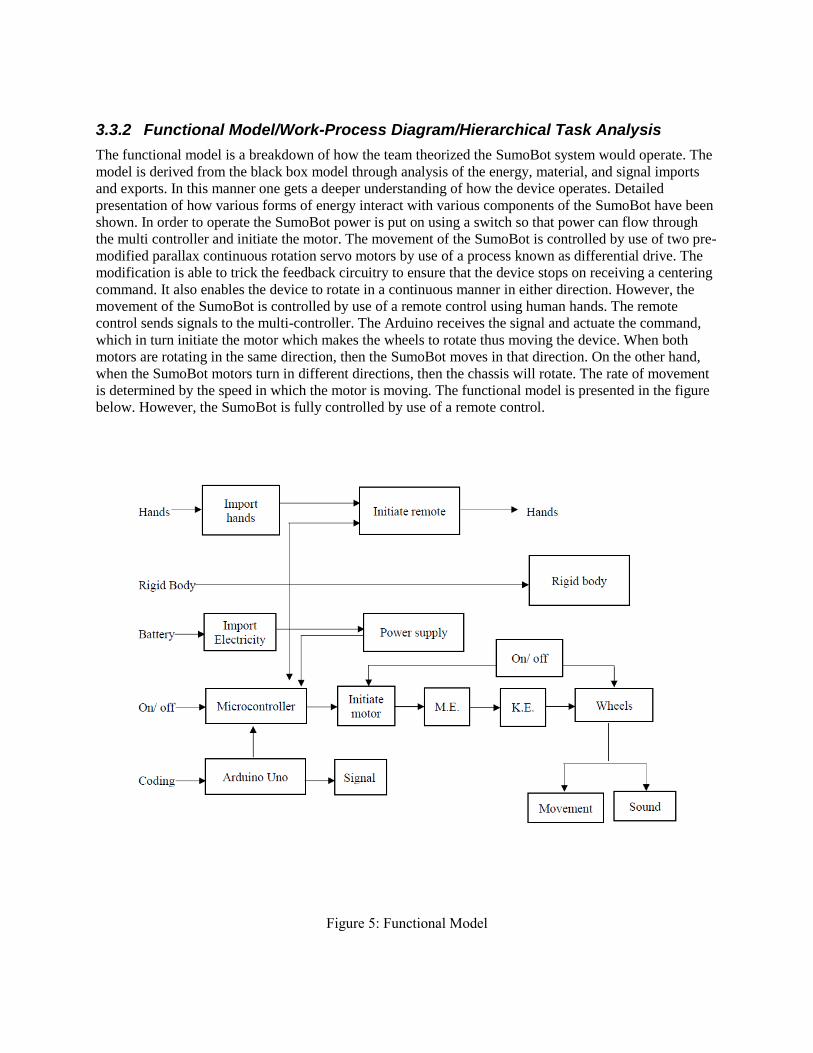
3.3.2 Functional Model/Work-Process Diagram/Hierarchical Task Analysis
The functional model is a breakdown of how the team theorized the SumoBot system would operate. The
model is derived from the black box model through analysis of the energy, material, and signal imports
and exports. In this manner one gets a deeper understanding of how the device operates. Detailed
presentation of how various forms of energy interact with various components of the SumoBot have been
shown. In order to operate the SumoBot power is put on using a switch so that power can flow through
the multi controller and initiate the motor. The movement of the SumoBot is controlled by use of two pre-
modified parallax continuous rotation servo motors by use of a process known as differential drive. The
modification is able to trick the feedback circuitry to ensure that the device stops on receiving a centering
command. It also enables the device to rotate in a continuous manner in either direction. However, the
movement of the SumoBot is controlled by use of a remote control using human hands. The remote
control sends signals to the multi-controller. The Arduino receives the signal and actuate the command,
which in turn initiate the motor which makes the wheels to rotate thus moving the device. When both
motors are rotating in the same direction, then the SumoBot moves in that direction. On the other hand,
when the SumoBot motors turn in different directions, then the chassis will rotate. The rate of movement
is determined by the speed in which the motor is moving. The functional model is presented in the figure
below. However, the SumoBot is fully controlled by use of a remote control.
Figure 5: Functional Model

3.4 Subsystem Level
The main function of this project is to create an RC SumoBot that capable of participating in the
SumoBot competition that include two R/C bots to compete against each other to win the battle. In order
to power the SumoBot it must have a battery which is placed in a certain compartment. The motors
facilitate movement of the robot by use of wheels fixed on the sides. The movements of the SumoBot are
controlled by use of a remote control. The content of the section below will be discussing the existing
designs for (1) motors, (2) batteries, (3) remote control system and (4) microprocessor system.
3.4.1 Subsystem #1: Motor
Motors are crucial in the SumoBots since they facilitate effectiveness in movements within the device.
Motors in the device also helps in improving the quality use as the SumoBot is able to move freely while
being operated.
3.4.1.1 Existing Design #1: Brushed Maxon DC Motors
Brushed Maxon DC motors are high-quality DC motors and are comprised of powerful permanent
magnets. The motor is made using the ironless rotor cutting-edge technology which ensure that the motor
has powerful drives and low inertia. In addition, it has a high rate of acceleration, motor is relevant to the
required function as it has high rate of acceleration and speed and relatively high torque which is highly
required in the robot. [6].
Figure 6: Brushed Maxon DC Motors [6]

3.4.1.2 Existing Design #2: Stepper Motor
This is a kind of motor which makes the shaft to rotate in a few degrees and then stop. In order to ensure
that there is a continuous rotation, the stepper motors make use of numerous notched electromagnets
which are arranged around a central equipment. Stepper motor may not be suitable for our robot as it is
used tasks that required high accuracy in movement but in our design we do not need this type of
accuracy as much as we need high speed and torque. [7].
Figure 7: Stepper Motors [7]
3.4.1.3 Existing Design #3: Servo Motor
This is a kind of motor that is used for accurate positioning of the SumoBot. It combines a continuous DC
motor with a “feedback loop” to facilitate accurate positioning. This motor is designed for specific tasks
where a motor position requires to be clear like moving various parts of the SumoBot and in our robot we
do not need this kind of accuracy as much as we need speed and torque so servo motor may not be
relevant to our robot. [8].
Figure 8: Servo Motor [8]

3.4.2 Subsystem #2: Batteries
Batteries are very crucial in SumoBot device since they provide energy that is needed to power the
device. There are a number of existing battery designs such as Cylindrical18650” batteries, Pouch Li-Poly
battery, and Prismatic NiMH battery which are as discussed below.
3.4.2.1 Existing Design #1: Cylindrical18650” batteries
These batteries are crucial since they provide a maximum voltage of 4.7 volts. The cells have an 18mm
diameter and are 65mm long. There are some which have a flat “+” terminal which makes it ready for
welding cells in a group to form battery packs. Others have a raised “+” terminal for easy insertion and
removal from a battery holder [9].
Figure 9: Cylindrical18650” batteries [9]
3.4.2.2 Existing Design #2: Pouch Li-Poly battery
These are batteries which are produced in form of thin, elastic slices that are stacked and inserted into the
pouches instead of being can-rolled. Lack of metal packaging makes them light and hence crucial for the
device as they will not add a lot of weight. Their slim nature makes them to be easily fitted into the device
[9].
Figure 10: Li-Poly — lithium polymer battery [8]

3.4.2.3 Existing Design #3: Prismatic NiMH battery This battery is enclosed in a metal can hence making it to be strong and free from explosion. The
enclosure makes the battery to be a bit heavier hence can add onto the weight of the device. However, it is
weather resistant due to the coating [9]
Figure 10: Prismatic NiMH battery [9]
3.4.3 Subsystem #3: Remote Control
A remote-control system is crucial in the SumoBot as it facilitates easy control by the operator when they
are at a distance. The remote control systems discussed include voice remote control, infra-red remote
control and radio remote control.
3.4.3.1 Existing Design #1: Ultrasonic remote control
This remote control system makes use of voice control. It is complicated and only requires a light tap, a
whistle or a voice input [10].
Figure 11: Ultrasonic remote control [10]

3.4.3.2 Existing Design #2: Infrared remote control
Infrared remote control makes use of light in order to operate a device. It also requires a line of sight to
operate the device and hence there is need to aim to the direction of receiver. However, it is cheap and
easy to encode with a multi-function remote control [10].
Figure 12: Infrared remote control [10]
3.4.3.3 Existing Design #3: Radio remote control
Radio remote control is used to control distant objects by use of radio signals which are transmitted using
the remote-control device. This kind of remote control has a complex circuit; is expensive but has the best
performance since it has farthest control distance and strong penetration ability [10].
Figure 13: Radio remote control [10]

3.4.4 Subsystem #4: Microcontroller
A microcontroller system is crucial in the SumoBot as it translate the signal to the motors. As a result, it
enables easier and efficient operation of the device.
3.4.4.1 Existing Design #1: Arduino Uno R3 USB Microcontroller
This microcontroller is of significant in this device since it has some specifications which are appropriate.
It has a wide variety of accessory "Shields" which are available. It also has a variety of I/O pins including
analog and digital. It also has an USB connection which facilitate connection to other devices [11].
Figure 14: Arduino Uno R3 USB Microcontroller [11].
3.4.4.2 Existing Design #1: Arduino Uno R3 USB Microcontroller
This design is characterized by a versatile, programmable robot tank kit, a complete Arduino board built-
in Arduino Uno, and is compatible with a variety of shields. Also, it has a Dual H-bridge and onboard
voltage regulator and hence there is only one battery which is required. In addition, it has an onboard
LiPo battery charger and solder prototyping area hence there is no need of soldering [11].

Figure 15: Arduino Uno R3 USB Microcontroller [11]
3.4.4.3 Existing Design #1: 16-bit Digital Signal Controller (DSC)
This design is crucial since it provides seamless operation while at the same time reducing power
consumption. It is also characterized by a self-contained system with memory, a processor and
peripherals. This design is highly appropriate in motor control, sensor processing and power conversion
applications [12].
Figure 16: 16-bit Digital Signal Controller (DSC) [12]
3.4.5 Subsystem #4: Wheels
A Wheel system is crucial in the SumoBot as it translates the rotational motion of the motors into robot
movement so the wheels should have high surface friction to be able to push opponents.
3.4.5.1 Existing Design #1: Omni Wheel
This Omni wheel provides 360° movement with rotational and sideways maneuverability and will make
the robot able to rotate 360° but it is not relevant to our design as it require a totally different motors
position design.

Figure 17: Omni Wheel
3.4.5.2 Existing Design #2: Rubber Wheel
This rubber wheel has high friction which makes it relevant to our robot.
Figure 18: Rubber Wheel
4 DESIGNS CONSIDERED
The team generated a total of 10 different designs during the brainstorming process based on the various
customer and engineering requirements. The first four designs which were considered are as discussed
below and the rest are presented in the appendix
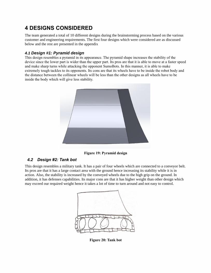
4.1 Design #1: Pyramid design This design resembles a pyramid in its appearance. The pyramid shape increases the stability of the
device since the lower part is wider than the upper part. Its pros are that it is able to move at a faster speed
and make sharp turns while attacking the opponent SumoBots. In this manner, it is able to make
extremely tough tackles to its opponents. Its cons are that its wheels have to be inside the robot body and
the distance between the collinear wheels will be less than the other designs as all wheels have to be
inside the body which will give less stability.
Figure 19: Pyramid design
4.2 Design #2: Tank bot
This design resembles a military tank. It has a pair of four wheels which are connected to a conveyor belt.
Its pros are that it has a large contact area with the ground hence increasing its stability while it is in
action. Also, the stability is increased by the conveyed wheels due to the high grip on the ground. In
addition, it has defenses capabilities. Its major cons are that it has higher weight than other design which
may exceed our required weight hence it takes a lot of time to turn around and not easy to control.
Figure 20: Tank bot

4.3 Design #3: Gripper
The design is made in such a manner that it has a magnetic field which results into a firm grip. Its major
pros are a strong magnetic field and big tires on the side to prevent getting flipped. This ensures that the
device is stable on the ground and it does not slide easily when attacked by an opponent SumoBot. Its
major cons are that it has tires which can break easily and an opponent SumoBot may not be gripped
easily and the team founds out that flipping is against the rules which makes this design useless.
Figure 21: Gripper
4.4 Design #3: Seoi Nage
This design comprised of rear and front protrusions for attacking the enemy bot. The components are
controlled by use of hydraulic springs. Its major pros are that it has a rear stick which acts as a stabilizer.
In this manner, the device is able to have a lot of stability while attacking or being attacked by an
opponent SumoBot. Its major con is that the hydraulic springs tend to make the device to be highly
bouncy while it is in real operations. Also, its big size makes it hard to operate especially when it is made
to turn.
Figure 22: Seoi Nage The rest of the 10 designs which were considered are presented in Appendix A

5 DESIGN SELECTED – First Semester
This section gives the explanation of the rationale that was used to select the most appropriate design for
the SumoBot that met the customer and engineering requirements. The design was carefully selected after
evaluations of the designs using a Pugh chart and a decision matrix.
5.1 Rationale for Design Selection
The first rationale which was used in the process of design process was use of a Pugh Chart, which
enabled the team to narrow the number of designs down to four which are represented below. Then from
the four designs a selection was made to get the design which meets most of the customer requirements.
The customer requirements which were considered in this selection process include a design that is: light
in weight; reliable; durable; portable; easy to operate; has pausing capabilities; remote controlled; safe to
other SumoBots and has low cost. The design which met a majority of the customer and engineering
requirements in all scenarios was set as the datum. In this case the design which was selected as the
DATUM is the Trapezoid design. In case a certain design exceeded the datum in a customer requirement,
it was given a plus (+), whereas the design which did not exceed the datum in a customer requirement
was given a minus (–). For designs which had a similarity in customer requirement were given an “S”.
Then, a summation of the pluses, minuses and “S” was done below each design. After using the Pugh
chart, the four designs which were selected so that they could be analyzed further in the decision matrix
include: tank bot, pyramid, dome, and umbrella designs. The Pugh chart which was used in narrowing
down the ten designs into four is represented in the table below.
A decision matrix was used in order to decide on the most appropriate design after being narrowed down
by the Pugh chart. In the table, the customer requirements are listed on the left and weighted in terms of
importance on a scale of 1 to 5. In this case, 1 is the least important whereas 5 is the most important. The

same scale is used in rating the designs in respect to the customer requirements. For instance, 1 is
awarded to the design which least fulfills the intended customer requirement; 3 is for the one which
averagely fulfills whereas 5 is for the one which fully fulfills the respective customer requirement. Then,
each rating on every design is multiplied by the customer requirement weighting and added together so as
to get the total score. After using the decision matrix, the pyramid design emerged the best with a score of
62 and hence was selected since it had met most of the customer and engineering requirements.
5.2 Design Description
The design which emerged the best in the project is the Pyramid design. The design resembles a pyramid
in its appearance. The lower section is 20 cm square while the upper part is 10 cm square. The pyramid
shape increases the stability of the device and hence it is able to make quick and stable maneuvers as it
pushes its opponent. The design has four wheels which are made up of rubber and this is crucial since it
helps to increase the grip of the device. The outer casing of the device is made up of aluminum 6061
hence making it to be strong and highly durable.
In order to operate the device; it is first of all powered on by using a switch. This powers the motors
hence making it ready for movement. Commands for moving the device are sent by use of mobile phone
with Bluetooth connection. The signal is received by Arduino which then actuates the command. The
remote control fully controls the SumoBot without any autonomous controls.

Figure 23: CAD Draft of the pyramid SumoBot
Figure 24: Multiple view CAD of the pyramid SumoBot
6 PROPOSED DESIGN – First Semester
The implementation and fabrication of the SumoBot has been described in this section.

6.1 Intended construction of the design
After selecting the pyramid design which have been discussed in section 5.2, the team made a decision of
printing a 3D prototype for a proof of concept. The team hopes to discover possible problems in the
designed from the prototype. This will help team to fix any problem and resketch if needed before starting
to manufacture the design. This will help to make the manufacturing process much easier and reliable.
This was to help in easy maintenance of the device in case some part failed or there was need of
improvement. After prototyping, the team will look forward to full incorporation. Lastly, prototyping is a
really important process since it confirms that everything works as intended and gives an idea of
improvements and changes needed.
6.2 Proposed Materials
In this project, it was crucial to select the appropriate materials that could be used in the making of the
pyramid SumoBot. The components which were selected were to be of high quality, strong, light in
weight, and durable. The strength of the materials was crucial since it ensured that the device was able to
withstand strong forces from the opponent SumoBots. Moreover, it facilitated easy operation and
movement of the device while it is in operation. Durability will enable the device to sustain numerous
tackles without breaking. The major materials that will be used in making the device include: Arduino
Uno; battery; motor, wheels; motor driver; transmitter and receiver; and the frame will be made of
aluminum 6061. The bill of materials which is presented in table below was made depending on the
materials that were selected. However, the prices that have been indicated are the relative prices which are
currently in the market.
Table 6: Proposed Design Bill of Materials
6.3 Proposed Budget
The estimated total cost for the project so far is $1309.27, and this covers everything needed to build the
sumobot from scratch. However, the price could be as low as $341.78 if the team were able to recycle the
old sumobots provided by the instructor. If the team were able to recycle all the parts, they would only
need to buy the frame material, machining, Arduino Uno, batteries, and wheels. The following table
shows the cost breakdown of the initial prototype.

6.4 Schedule
In order to make sure that the team meets the deadlines of the project, other team set up a Gantt chart.in
this manner, the team was able to organize themselves on significant milestones and deadlines. The Gantt
chart that was used is presented in table 8 Appendix B.

7 IMPLEMENTATION – Second Semester
Final design was changed to fit the manufacturing processes and assembly processes which was done to
the design, so the complete final design of the robot has changed as follow after replacing some of the
parts and after building the exterior body. The figure below shows the result of the changes with a CAD
model and details will be discussed in this chapter.
Figure 25: Final CAD draft of SumoBot
7.1 Manufacturing
Most of the SumoBot will be assembled of many components that was bought but the exterior body and
the second layer to be manufactured based on the design and each was based on calculations that was
done to make sure the best material were used. The process of manufacturing started during winter break
between the semesters which gave the team a better machines to use in the Kuwait Scientific Club.

7.1.1. Exterior Body:
The exterior body was made of aluminum sheet metal which was cut using Laser cutting machine
available in the Kuwait Scientific Club based on the designed flatten sheet metal as seen below. The
aluminum 6061 was used as the body material after comparing it to Mild Steel and Brass. The aluminum
had enough strength to with stand impacts with lighter weight. The Calculations are presented in
Appendix C.
Figure 27: Flatten exterior body aluminum sheet After cutting the aluminum sheet using the laser cutting machine a hydraulic sheet metal bending machine
was used to bend the sides of the cut aluminum sheet which was also available in the Kuwait Scientific
Club to make the pyramid shape as seen below.

Figure 28: Exterior aluminum body after bending
7.1.2 Control wooden frame:
Wooden Frame will be used to carry the electronic parts in the upper side of the sumobot and we chose to
use wood as it helps to control the heat generated from the electronic parts. Moreover, the wood was used
as it does not conduct the heat generated by the motors inside the design. The wood was bought from
Home Depot and the manufacturing process was done in Ace Hardware workshop. The frame was cut
based on the design below.
Figure 29: Wooden frame parts After Cutting off the wooden frame the wooden parts will be assembled using bolts and nuts to form the
wooden frame as the figure shows below.
Figure 29: Wooden frame after assembly
7.2 Design Changes
The design went through some changes after the first semester which helped improving the design and
achieving the goals of the design. The changes focused in having the best possible power from the motors
by avoiding the use of gears and to control the heat inside the design.
7.2.1 Design change #1
Based on the calculations the team did about the gears, the team found out that some of the speed will be
lost from the gears with a lot more space required to mount them properly. As a result, the team tried their
best to find a relative solution to avoid using gears. This changed to plan to fix 2 motors on the robot: one
motor on the rear left wheel and the other on the right front wheel and to leave the other 2 wheels idle,
which gave the team a problem in fixing the idle wheels while maintaining the robot balance as in the
design each wheel has to be fixed separately. The calculations are presented in Appendix C.
So to fix the idle wheel we had to manufacture some sort of support using wood and a ball bearing but it
failed to maintain balance of the robot because we manufactured this support manually.
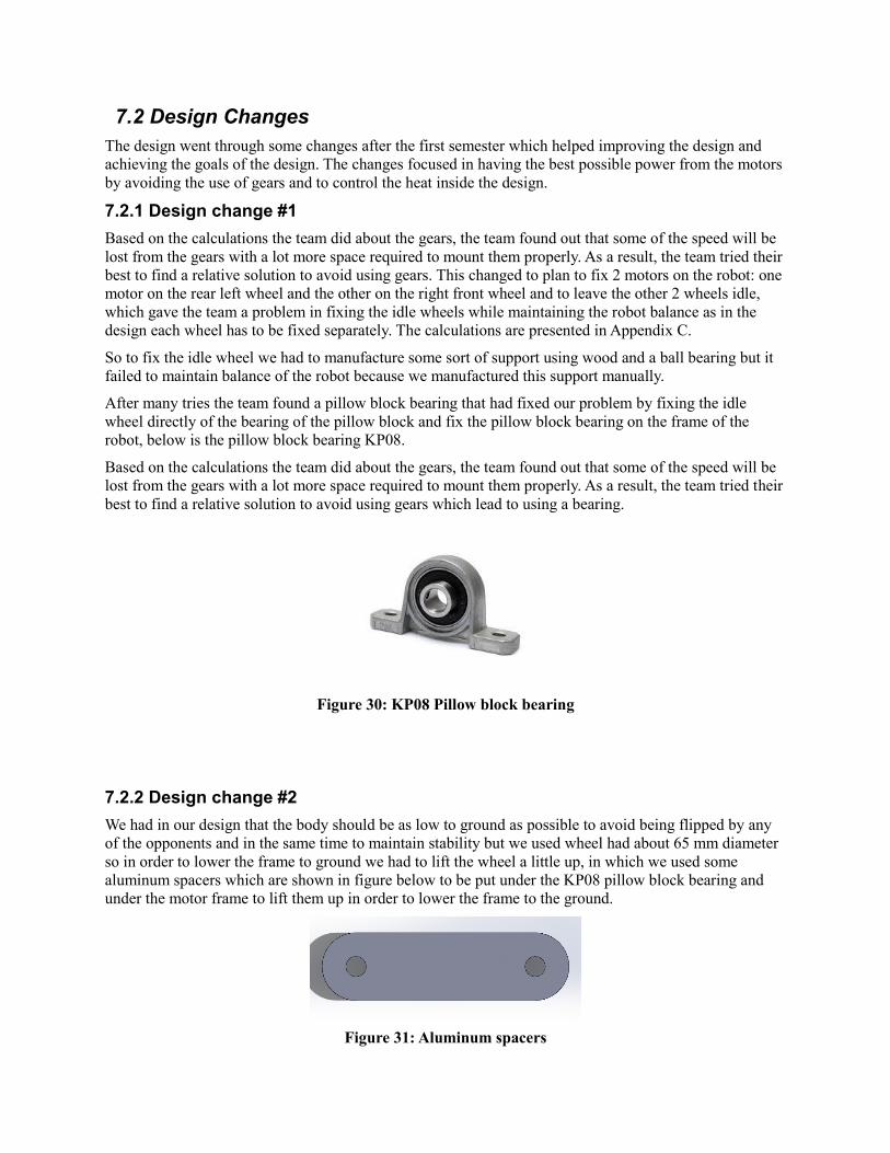
After many tries the team found a pillow block bearing that had fixed our problem by fixing the idle
wheel directly of the bearing of the pillow block and fix the pillow block bearing on the frame of the
robot, below is the pillow block bearing KP08.
Based on the calculations the team did about the gears, the team found out that some of the speed will be
lost from the gears with a lot more space required to mount them properly. As a result, the team tried their
best to find a relative solution to avoid using gears which lead to using a bearing.
Figure 30: KP08 Pillow block bearing
7.2.2 Design change #2
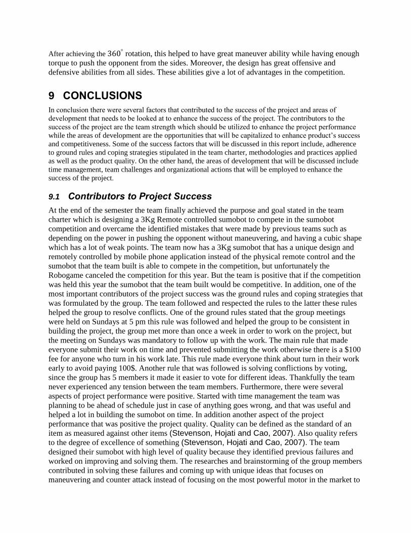
We had in our design that the body should be as low to ground as possible to avoid being flipped by any
of the opponents and in the same time to maintain stability but we used wheel had about 65 mm diameter
so in order to lower the frame to ground we had to lift the wheel a little up, in which we used some
aluminum spacers which are shown in figure below to be put under the KP08 pillow block bearing and
under the motor frame to lift them up in order to lower the frame to the ground.
Figure 31: Aluminum spacers

7.2.3 Design change #3
In our first design we had a flat aluminum second floor to hold the control parts. However, considering
the heat caused by the parts while operating the team decided to change the material to wood. In addition,
each component will be separate with wooden walls to make sure the heat is controlled and does not
cause any problems.
Figure 32: Wooden frame of the 2nd floor.
7.3 Final Budget
The estimated total cost of the project was actually lower than estimated in the first semester. It went
down to $1226 from $1309.27. This was a result of changing some of the parts. The team was not able to
salvage any parts from the old sumobots provided by the instructor. The following Table shows the total
cost breakdown.
Table 7: Budget
Part Quantity Price
Li-po Battery 2 $137
Hc-05 Bluetooth module 2 $21
Arduino uno 2 $40
Breadboard 1 $3
Rubber Wheels 6 $35
Motors 2 $400
Battery Charger 1 $69
Monstershield Motor Driver 2 $86
Power Bank 1 $15
Bearings 4 $20
Manufacturing - $85
Screws and nuts - $10
Wires - $5
Laser Cutting - $20
Shipping - $270
Wooden board 1 $10
Total Cost $1226

7.4 Schedule
In order to make sure that the team meets the deadlines of the project, other team set up a Gantt chart.in
this manner, the team was able to organize themselves on significant milestones and deadlines. The Gantt
chart that was used is presented in Appendix B for both ME 476C and ME 486C.
7.5 Final Bill of Materials
The proposed Bill of materials was changed after changing the design because of unavailability of the
parts and to fit the manufacturing processes and assembly processes of some parts. Below is the table of
the components used in the final design.
Part No. Part Name Qty. Description
1 Arduino UNO 1 Microcontroller
2 Battery 1 LIPO battery 1100 mAh
3 Motor 2 Motor 250 rpm and 8.8 kg/cm torque
4 Wheel 4 Rubber Wheel
5 Driver 1 Monster motor shield VNH2SP30
6 Bluetooth Module 1 HC05 Bluetooth Module
7 Aluminum Body 1 Metal Body
8 Power Bank 1 2000 mAh power bank
9 Block bearing 2 KP08 housing pillow block bearing
10 Wooden Frame 1 Controlling electronic parts on top of the device
11 Coupler 4 Connect the tires to the bearings and motors.
12 Motor fixation 2 Holds the motors in place.
13 Control Fixation 4 Holds the wooden frame in place.
14 Shaft 2 Shafts are connected from the bearing to the
tires through the couplers.
15 Spacers 2 A spacer beneath each bearing to hold in place
and to keep it high enough.
Table 10: Current Bill of Materials

Final Design exploded view:
Figure 26: Final exploded CAD draft of SumoBot
8 TESTING
After the full design was manufactured the team went through a testing procedure to make sure
all the engineering requirement went as intended. This will help the team to figure out any
changes needed for the design to get the best possible final product.
Table 8: Testing procedure and results
Testing Procedure Result
Assembly Time ~55mins
Tough Exterior Body Strong and withstood impacts.
Dimensions
Length 20cm
Width 20cm
Height 15cm
Battery Life 10 mins and 15 seconds of full performance.
Weight 2.5kg
Remote Control Fully remote controlled and easy to operate.
Pushing Capabilities Had enough speed and torque to easily push
old sumobots.

Safe to other SumoBots Did not inflict any damages to other sumbots
during testing.
Pausing Capabilities Completely stops when needed.
Cost $1226
Competitive Great Maneuver abilities and effective from
all sides.
1. Assembly time During the manufacturing process the team had to disassemble and reassemble the design from scratch
multiple times. Each time the team made sure to have a timer watch to check how long it takes to fully
assemble the sumobot, and each time it takes around 55 minutes.
2. Tough Exterior Body
The team tested the sumobot against the old sumobots provided by the team instructor. The sumobot was
able to withstand all the impacts during the testing without any deformations.
3.Dimensions
The length, width and height of the device were measured by using a measure tape in centimeters. The
results of the SumoBot size was 20 cm x 20 cm x 15 cm.
4.Battery Life
The team managed to check how long the sumobot have the performance possible before starting to lose
power gradually. The team found out it takes 10 mins and 15 seconds before the sumobot starts to lose
full performance. This will help the team know when to change the batteries during the competition.
3. Cost efficient The prices of all the components and services used in Robot building were summed up and they did not
exceed the budget of $1500.
4. Weight The weight of the device was determined, and it was 2.5kg which does not exceed the limit of 3kg.
5. Remote Control
After the team completed the codes, the team tested all the commands to check that everything worked as
intended. Moreover, the team made sure that the sumo bot is easy to control and achieved 360°
rotation.
6.Pushing Capabilities By using the old sumobots provided by the instructor, the team were able to test out the pushing
capabilities to make sure that the sumobot has enough torque and speed as intended. The test was
successful as the sumobot managed to easily push the old sumobots.
7. Safe to Other Sumobots
During the pushing capabilities testing the team made sure to check if there was any damage inflicted to
the old sumobots, for this is against the rules and regulations of the competition. Moreover, the sumobot
did not flip the sumobots or damage the floor which are also in the rules.
8.Pausing Capabilities
Whenever the team stops sending commands the sumobot comes to an immediate stop while still
connected to the remote control. This meets the requirement as having the ability of pausing and resuming
since the judge can stop the match anytime needed and resume it.
9. Cost efficient The prices of all the components and services used in Robot building were summed up and they did not
exceed the budget of $1500. In fact, the team was able to be $274 below the budget as the cost was
$1226.
10. Competitive
After achieving the 360° rotation, this helped to have great maneuver ability while having enough
torque to push the opponent from the sides. Moreover, the design has great offensive and
defensive abilities from all sides. These abilities give a lot of advantages in the competition.
9 CONCLUSIONS
In conclusion there were several factors that contributed to the success of the project and areas of
development that needs to be looked at to enhance the success of the project. The contributors to the
success of the project are the team strength which should be utilized to enhance the project performance
while the areas of development are the opportunities that will be capitalized to enhance product’s success
and competitiveness. Some of the success factors that will be discussed in this report include, adherence
to ground rules and coping strategies stipulated in the team charter, methodologies and practices applied
as well as the product quality. On the other hand, the areas of development that will be discussed include
time management, team challenges and organizational actions that will be employed to enhance the
success of the project.
9.1 Contributors to Project Success
At the end of the semester the team finally achieved the purpose and goal stated in the team
charter which is designing a 3Kg Remote controlled sumobot to compete in the sumobot
competition and overcame the identified mistakes that were made by previous teams such as
depending on the power in pushing the opponent without maneuvering, and having a cubic shape
which has a lot of weak points. The team now has a 3Kg sumobot that has a unique design and
remotely controlled by mobile phone application instead of the physical remote control and the
sumobot that the team built is able to compete in the competition, but unfortunately the
Robogame canceled the competition for this year. But the team is positive that if the competition
was held this year the sumobot that the team built would be competitive. In addition, one of the
most important contributors of the project success was the ground rules and coping strategies that
was formulated by the group. The team followed and respected the rules to the latter these rules
helped the group to resolve conflicts. One of the ground rules stated that the group meetings
were held on Sundays at 5 pm this rule was followed and helped the group to be consistent in
building the project, the group met more than once a week in order to work on the project, but
the meeting on Sundays was mandatory to follow up with the work. The main rule that made
everyone submit their work on time and prevented submitting the work otherwise there is a $100
fee for anyone who turn in his work late. This rule made everyone think about turn in their work
early to avoid paying 100$. Another rule that was followed is solving conflictions by voting,
since the group has 5 members it made it easier to vote for different ideas. Thankfully the team
never experienced any tension between the team members. Furthermore, there were several
aspects of project performance were positive. Started with time management the team was
planning to be ahead of schedule just in case of anything goes wrong, and that was useful and
helped a lot in building the sumobot on time. In addition another aspect of the project
performance that was positive the project quality. Quality can be defined as the standard of an
item as measured against other items (Stevenson, Hojati and Cao, 2007). Also quality refers
to the degree of excellence of something (Stevenson, Hojati and Cao, 2007). The team
designed their sumobot with high level of quality because they identified previous failures and
worked on improving and solving them. The researches and brainstorming of the group members
contributed in solving these failures and coming up with unique ideas that focuses on
maneuvering and counter attack instead of focusing on the most powerful motor in the market to
meet the engineering requirements of cost efficient and weight. The success of this project can be
attributed to the tools used in the design phase, and the different team member’s team member’s
skills. Solid works played a big role in the designing phase of the project. Since solid works
gives the opportunity to easily edit on the design and makes the manufacturing process easier.
Additionally to the solid works the team members were skilled differently, so every person in the
group played an important role in contributing to the success of the device. One of the group
members was responsible for group meeting and dividing the work equally, another team
member is expert in Solid Works his abilities helped to improve the design and solve the design
problems before even building the device by analyzing the design through solid works. The team
hired one of the team as a financial advisor, his main role was to control the budget and make it
cost effective. However, the team was very flexible on changing the tasks between themselves,
so technically every member of the group was able to perform every task in the project. Team
work was the main methodology that helped in designing a competitive sumobot, keeps the
budget down and keeps the members of the group motivated and finished the building process on
time.
9.2 Opportunities/areas for improvement
Despite all the positive aspects mentioned above the project had few negative aspects that the
group faced, such as coding the group took long time and did many tests to improve their coding
for the device, but that was expected since no one in the group have a basic knowledge for
coding. Especially that the group wanted a 360 degrees rotational movement and that was not
easy to code. The team did their best to overcome the problem with great determination. This
issue was not avoidable since the group members assigned coding to two student only, but the
team was flexible to help anytime with the coding. Finally the problem was solved and the team
members were able to successfully code the device and the project was built on scheduled time.
In addition the team planned to reuse some of the previous team’s parts, but unfortunately this
was waste of time because most of the parts were difficult to take off from the devices and some
of them were not able to reuse due to permanent wear. Furthermore the previous devices has
common cubic shape which made it more impossible to the group members to test different
shapes of the devices to make their decision. Despite all of this the team was able to build a
competitive device. Ensuring that the tasks are well divided between the team members, sometimes
equal dividing is not effective but assigning each task to the quality strength of the team member will
ensure that the task will be delivered with quality. Furthermore, collaborating and working as a team and
sharing ideas and thoughts, as well as researching definitely will improve the performance of team.
Moreover, scheduling ahead of time and monitoring the schedule planned is the key to success. The key
for every successful team is respect and collaboration between team members. Far from the respect
between the team members the team learned multiple skills during this project. None of the team
members had any experience in manufacturing, coding or setting up electronic parts. But, with research
and communicating with experts the team gained the skills to build the device properly. For example in
manufacturing the team had the advantage to work in Kuwait during the winter break, which gave the
team the opportunity to use machines that may not be available or hard to find in university machine shop
such as laser cutting machine and hydraulic bending machine, these two machines are the main reason to
achieve the unique design of pyramid. For coding and setting up the electronic parts the team never had a
chance before to perform those kind of skills, but with research and practicing the team was able to
success in those tasks.

10 REFERENCES
[1] "MINDSTORMS SUMO BOT COMPETITION RULES", Tnvalleyfair.org, 2016. [Online].
Available: https://www.tnvalleyfair.org/assets/sumo-bot-rules-tennessee-valley-fair-2018.pdf. [Accessed:
21- Nov- 2018].
[2] Robogames.net. (2018). Unified Sumo Robot Rules. [Online] Available at:
http://robogames.net/rules/all-sumo.php [Accessed 15 Oct. 2018].
[3] AE Dimensions Pvt Ltd. (2017). 'SAND FLEA' THE JUMPING ROBOT - AE Dimensions Pvt Ltd.
[online] Available at: http://blog.aedimensions.com/sand-flea-the-jumping-robot/ [Accessed 15 Sep.
2018].
[4] M. », "DIY RC Android SumoBot (Sumo Robot)", Instructables.com, 2018. [Online].
Available: https://www.instructables.com/id/Android-Controlled-Bluetooth-SumoBot-Ultimate-DIY-/.
[Accessed: 15- Sep- 2018].
[5] Robot, S. (2018). SumoBot Robot. [Online] Trossenrobotics.com. Available at:
https://www.trossenrobotics.com/parallax-SumoBot-robot.aspx [Accessed 15 Oct. 2018].
[6] Maxonmotor.com. (2018). DC motors and drive systems by maxon motor. [Online] Available at:
https://www.maxonmotor.com/maxon/view/content/index [Accessed 15 Oct. 2018].
[7] "Difference between DC Motor, Servo Motor and Stepper Motor", ElProCus - Electronic Projects for
Engineering Students, 2018. [Online]. Available: https://www.elprocus.com/difference-dc-motor-servo-
motor-stepper-motor/. [Accessed: 21- Nov- 2018].
[8] "Choosing a Motor: DC, Stepper, or Servo - Free How-to Robot Construction Article", Robotoid.com,
2018. [Online]. Available: http://www.robotoid.com/howto/choosing-a-motor-type.html. [Accessed: 19-
Nov- 2018].
[9] Jarema, R. (2018). Batteries — choose the right power source for your robot. [Online] Medium.
Available at: https://medium.com/husarion-blog/batteries-choose-the-right-power-source-for-your-robot-
5417a3ec19ca [Accessed 15 Oct. 2018].
[10] Windsor, S. (2018). 3 main types of remote control and their applications | GearBest Blog. [Online]
GearBest. Available at: https://www.gearbest.com/blog/how-to/3-main-types-of-remote-control-and-their-
applications-2769 [Accessed 28 Jun. 2018].
[11] "Microcontrollers", 2018. [Online]. Available: https://www.robotshop.com/en/microcontrollers.html.
[Accessed: 19- Nov- 2018].
[12] "Microcontrollers Online Store | Future Electronics", Futureelectronics.com, 2018. [Online].
Available: https://www.futureelectronics.com/c/semiconductors/microcontrollers. [Accessed: 21- Nov-
2018]
[13] Nau.edu. (2018). Print Logos - School of Forestry - Northern Arizona University. [Online] Available
at: https://www.nau.edu/CEFNS/Forestry/Student-Resources/Information-Technology/Print-Logos/
[Accessed 16 Oct. 2018]
[14]"Metals and Alloys - Densities", Engineeringtoolbox.com, 2018. [Online]. Available:
https://www.engineeringtoolbox.com/metal-alloys-densities-d_50.html.
[15]"ASM Material Data Sheet", Asm.matweb.com, 2018. [Online]. Available:
http://asm.matweb.com/search/SpecificMaterial.asp?bassnum=ma6061t6
[16] Stevenson, W. J., Hojati, M., & Cao, J. (2007). Operations management (Vol. 8). Boston: McGraw-
Hill/Irwin.

11 APPENDICES
11.1 Appendix A: Designs considered
Trapezoid design This design resembles a trapezoid. Its major pros are that it has a strong wheel base, and a crane in the
front to lift the opponent to make it easier to push them outside the ring. However, the cons were that the
crane could be useless since most SumoBots were very low in the front and made it hard to utilize the
crane.
Figure 23: Trapezoid design
Dome design This design mimics a dome on its upper part. On the lower section it is wide to facilitate stability. Its pros
are that it is has higher levels of safety, durable, and its unflappable. Its cons are that it is hard to create it
within the weight limit. In addition, the team found out its not allowed to flip the opponents which makes
this design impractical which makes the team avoid thinking about how to counter getting flipped.
Figure 24: Dome design

Crescent design This design resembles the crescents moon on one side where there is a magnetic attraction. The design
has several pros including having sharp and very low blade to be able to lift the opponent easily. In
addition, it has a magnetic field in the body to hold the opponent after lifting them. On the other hand, its
cons were having lower than average defensive capabilities since it’s hard to get enough weight with this
design.
Figure 25: Crescent design
Cuboid design This design is composed of a cuboid with four wheels. While the upper part has a curved arm, which has
a magnetic edge. The pros associate with the device is that it has a high level of stability. However, the
cons were that it was hard to fit this design in the required size. Moreover, it was hard to find a strong
enough magnet to be able to lift the opponents from above.
Figure 26: Cuboid design

Shovel design The major pros in this design that it has two stances which were from utilizing the shovel shape. For
attacking the shovel will lean forward and act as the design blade to push the opponent. In addition, the
shovel is also used in a defensive way as the shovel will lean back to act as a drag mechanism to make it
hard for the opponent to push the design. The cons for this design were begin light weight and having
only two wheels which makes it unstable.
Figure 27: Umbrella design
Scissors design This design utilizes a unique mechanism to counter being lifted. The front blades will be able to move
sideways as a defensive technique which helps getting recovered after getting lifted from the opponent.
However, the cons of this design are the weight limit in the competition since the design will get a lot of
weight to accomplish this idea.
Figure 28: Scissors design

11.2 Appendix B: Gantt chart
Table 8: Gantt chart
Table 9: 2nd -semester Gantt chart

11.3 Appendix C: Calculations
11.3.1 Exterior Body Material Calculations
ASSUMPTIONS
Table 1: Variables used Variable Units Value
Mass Kilograms (kg) 3
Time Seconds (s) 2
Acceleration a (m/s2) 0.05
Length L Meters (m) 0.2
Width w Meters (m) 0.2
Thickness b Meters (m) 0.003
Impact Area A (m2) 0.002
Density ρ (kg/m3) 2700
The volume of the pyramid assuming a uniform sheet thickness of 3mm with an open top is given by:
𝑣 =𝑙𝑤ℎ
3=
𝑙1𝑤1ℎ1
3−
𝑙2𝑤2ℎ2
3=
0.2𝑥0.2𝑥0.1
3−
0.194𝑥0.194𝑥0.097
3= 3.49𝑥 10−4𝑚3
Table 2: Masses of different frame materials of the same volume [14] Material Density kg/m3 Mass kg
Mild steel 7850 2.74
Aluminum 2720 0.94
Brass 8470 2.96
A. Impact Resistance
𝐸𝑘 =1
2𝑚𝑣0
2 =1
2𝑥 3 𝑥 0.12 = 0.015𝐽
Impact resistance is the amount of energy that the frame could absorb on impact without permanent
deformation.
The amount of energy absorbed by the frame on impact (U) is a factor of the yield stress σ, Area
A, thickness b, and elastic modulus E as given by [15]:
𝑈 =𝜎2𝐴𝑏
2𝐸=
(276 𝑥 106)2 𝑥 0.002 𝑥 0.003
2 𝑥 69 𝑥 109= 3.312 𝐽
Since the impact energy is much higher than the kinetic energy on impact, the design would be able
to withstand the impact.
B. Yield Strength The force imparted on the sumobot when the opponent robot moving at an initial velocity 𝑣0
collides with it is given by:
𝐹 = 𝑚𝑎 = 3 𝑥 0.05 = 0.15𝑁 The normal stress of the material after collision due to a force F on impact cross sectional area A is
given by:
𝑆𝑡𝑟𝑒𝑠𝑠, 𝜎 =𝐹
𝐴=
0.15
0.002= 75 𝑁/𝑚2
The normal strain of the material after collision measures the deformation of the frame due to
impact.
𝐹 = 𝜎𝐴 = 240 𝑥 106𝑁
𝑚2𝑥 0.002 𝑚2 = 480,000𝑁

The safety factor is the ratio between the frame ultimate strength and the force applied to the body.
𝑆𝑎𝑓𝑒𝑡𝑦 𝑓𝑎𝑐𝑡𝑜𝑟 =480 𝑥 106
75= 6.4 𝑥 106
RESULTS
The frame of the robot meets the specifications required for the competition including the weight
and safety. The structure is sturdy enough to withstand impact on collisions and offers high maneuverability.
The opponent robot of 3kg with an acceleration of 0.05m/s2 imparts a stress of 75 Pa. Since the yield
strength of aluminum is 276 MPa [15], this design is safe from yield due to impacts in the competition. This
makes the robot efficient in competing and winning against other sumobots of the same class.
11.3.2 Gears Calculations
The team have used a motor with 8.8 kg.cm torque which will produce a force and speed of:
𝑇𝑜𝑟𝑞𝑢𝑒 = 𝑓𝑜𝑟𝑐𝑒 ∗ 𝑟𝑎𝑑𝑖𝑢𝑠 8.8𝐾𝑔. 𝑐𝑚 = 𝑓𝑜𝑟𝑐𝑒 ∗ 2.7 𝑐𝑚
𝑓𝑜𝑟𝑐𝑒 =8.8 𝐾𝑔. 𝑐𝑚
2.7𝑐𝑚
𝑓𝑜𝑟𝑐𝑒 = 3.25 𝐾𝑔 𝐿𝑖𝑛𝑒𝑎𝑟 𝑠𝑝𝑒𝑒𝑑 = 𝑀𝑜𝑡𝑜𝑟 𝑟𝑝𝑚 ∗ 𝑐𝑖𝑟𝑐𝑢𝑚𝑓𝑒𝑟𝑒𝑛𝑐𝑒 𝑜𝑓 𝑡ℎ𝑒 𝑤ℎ𝑒𝑒𝑙
𝑆𝑝𝑒𝑒𝑑 = 250 ∗ (2 ∗ 𝜋 ∗ 2.7) 𝑆𝑝𝑒𝑒𝑑 = 4242 𝑐𝑚/ min = 70.6 𝑐𝑚/𝑠 = 0.706 𝑚/𝑠
If gears were used with our motor we would have two options for our gears:
1. Gears have a 1:1 ratio which would only transmit the torque and speed as they are from
the motor to the wheels
2. Gears with a 2:1 ratio as the gears on the wheels would be limited to 30 mm diameter due
to wheel shaft height from the base which cannot be increased.
In case of 1:1 gear ratios: 𝐷1
𝐷2=
𝑇1
𝑇2=
𝑁2
𝑁1= 1
30
30=
8.8
8.8=
250
250= 1
But we must consider the gears efficiency in our calculations, so we can assume a 10% gears efficiency
which would result in about (0.9*8.8=7.9 kg.cm) which will lower our torque which is a disadvantage for
our robot in the competition.
In case of 2:1 gear ratios: 𝐷1
𝐷2=
𝑇1
𝑇2=
𝑁2
𝑁1= 1
60
30=
17.6
8.8=
125
250= 2
𝐿𝑖𝑛𝑒𝑎𝑟 𝑠𝑝𝑒𝑒𝑑 = 𝑔𝑒𝑎𝑟𝑠 𝑟𝑝𝑚 ∗ 𝑐𝑖𝑟𝑐𝑢𝑚𝑓𝑒𝑟𝑒𝑛𝑐𝑒 𝑜𝑓 𝑡ℎ𝑒 𝑤ℎ𝑒𝑒𝑙 𝑆𝑝𝑒𝑒𝑑 = 125 ∗ (2 ∗ 𝜋 ∗ 2.7) 𝑆𝑝𝑒𝑒𝑑 = 2121 𝑐𝑚/ min = 35.3 𝑐𝑚/𝑠 = 0.353 𝑚/𝑠
But we must consider the gears efficiency in our calculations, so we can assume a 10% gears efficiency
which would result in about (0.9*17.6=15.8 kg.cm), this will give us a significant advantage with the
increase of torque but it lowered the speed to the half, and the speed is an important thing.