Embed Size (px)
Citation preview

Manual Revision: 4.0 Firmware version 1.18.00 and Above Date Released: 2021-04-01 ©2020 DynaGen Technologies Inc.
TE600A User Manual

TOUGHSeries PRO
1
Table of Contents
TE600A User Manual ...................................................................................................... 0
Table of Contents ............................................................................................................ 1
Table of Figures .............................................................................................................. 5
Introduction ..................................................................................................................... 6
Overview ...................................................................................................................... 6
Features and Functions ...................................................................................................... 6
Displays .............................................................................................................................. 6
Specifications .................................................................................................................. 7
Testing Specification .................................................................................................... 7
Battery Supply .................................................................................................................... 8
Display ................................................................................................................................ 8
I/O ....................................................................................................................................... 8
Speed Sensing ................................................................................................................... 9
Communication Ports .......................................................................................................... 9
Mechanical .......................................................................................................................... 9
Other Features and Specifications ...................................................................................... 9
Installation ..................................................................................................................... 10
General Wiring Notes ................................................................................................. 12
Terminal Descriptions ................................................................................................ 14
Typical Wiring ................................................................................................................ 17
Speed Sensing ........................................................................................................... 17
CANBUS (J1939) and MODBUS (RS485) Connection .............................................. 17
AC Current (CTs) ....................................................................................................... 17
Sensors and I/O ......................................................................................................... 18
Wiring Considerations ................................................................................................ 20
Emergency Stop Wiring ............................................................................................. 20
Auxiliary Sensors ....................................................................................................... 21
CAN Bus Wiring ......................................................................................................... 22
Modbus Wiring ........................................................................................................... 23

TOUGHSeries PRO
2
ECM Wiring ................................................................................................................ 24
Current Transformers ................................................................................................. 25
Using the Controller....................................................................................................... 26
Front Panel and Buttons ............................................................................................ 26
Using the Menu System ............................................................................................. 27
Modes, Starting and Stopping .................................................................................... 30
Cranking Behaviour ................................................................................................... 31
Using Warmup Mode ................................................................................................. 32
Using Cooldown Mode ............................................................................................... 32
Configuration ................................................................................................................. 35
Options ...................................................................................................................... 35
Load Factory Defaults ........................................................................................................35
Controller Password ...........................................................................................................35
User ID & Settings Name ...................................................................................................35
Operator Setup .......................................................................................................... 36
Display Configuration .................................................................................................... 37
Quick Menu – Generic Start/Stop Page ..................................................................... 39
Programmable Logic ..................................................................................................... 40
Switched Inputs ............................................................................................................. 44
Switched Outputs .......................................................................................................... 46
Switched Output-Warnings ........................................................................................ 46
Switched Output-Failures ........................................................................................... 48
Switched Output - Other Functions ............................................................................ 50
Programmable Output ................................................................................................ 52
Event Log ................................................................................................................... 35
Engine Speed ................................................................................................................ 53
Speed Settings ........................................................................................................... 53
Engine Speed Setpoints ............................................................................................ 54
ECM Speed Control Modes ....................................................................................... 54
Manual Start ......................................................................................................................54
Remote Start ......................................................................................................................55
TSC1 Speed Settings ........................................................................................................56
TOUGHSeries PRO
3
Auto Ramping Setup ..........................................................................................................57
Front Panel Speed Control .................................................................................................57
Closed Loop Control .................................................................................................. 58
Sensors ......................................................................................................................... 60
System Battery ........................................................................................................... 60
Engine Temperature .................................................................................................. 61
Oil Pressure ............................................................................................................... 62
Fuel Level .................................................................................................................. 63
Auxiliary Sensors ....................................................................................................... 64
Temperature Fault Monitoring Example .............................................................................67
Virtual Auxiliary Sensors ............................................................................................ 68
Timers & Scheduler ....................................................................................................... 70
Engine Timer Logic .................................................................................................... 70
Idle .....................................................................................................................................72
Preheat Mode ....................................................................................................................73
OFF Key Function ..............................................................................................................73
Schedulers ................................................................................................................. 74
Exercise Scheduler ............................................................................................................74
Weekly Scheduler ..............................................................................................................75
Engine Maintenance Schedule ...........................................................................................75
AC Monitoring ............................................................................................................... 77
Genset Voltage .......................................................................................................... 77
Voltage Setpoints ...............................................................................................................77
AC Voltage Select ..............................................................................................................78
Frequency Setpoints ..........................................................................................................79
Genset Current .......................................................................................................... 80
Protections .........................................................................................................................81
Genset Power ............................................................................................................ 83
Power Setpoints .................................................................................................................84
Setting ...............................................................................................................................84
Range ................................................................................................................................84
Description .........................................................................................................................84
Current Transformers Involving Power Factor ....................................................................84

TOUGHSeries PRO
4
Communications ........................................................................................................... 86
J1939 CAN Bus ......................................................................................................... 86
MOD Bus (RS485) ..................................................................................................... 88
Remote Inputs ............................................................................................................ 89
Miscellaneous ............................................................................................................... 90
Password ................................................................................................................... 90
Thomson Actuator ...................................................................................................... 90
Fuel Select ................................................................................................................. 92
Troubleshooting ............................................................................................................ 93
Contact Information ....................................................................................................... 94

TOUGHSeries PRO
5
Table of Figures
Figure 1: Mounting Cut-Out .......................................................................................................11
Figure 2: Controller Dimensions ................................................................................................13
Figure 3: Main Connector - J1 (AMPSEAL 35-pin) ....................................................................14
Figure 4: Auxiliary Connector - J2 (AMPSEAL 35-pin) ..............................................................15
Figure 5: Typical Wiring Diagram ..............................................................................................19
Figure 6: Emergency Stop Wiring Diagram ...............................................................................20
Figure 7: Universal Sensor Wiring Example ..............................................................................21
Figure 8: Communications Wiring .............................................................................................22
Figure 9: ECM Wiring ................................................................................................................24
Figure 10: CT Wiring .................................................................................................................25
Figure 11:Controller Button Descriptions ...................................................................................26
Figure 12: LCD Screen Button Descriptions ..............................................................................27
Figure 13: Passcode .................................................................................................................29
Figure 14: Home Screen ...........................................................................................................29
Figure 15: Cooldown Functionality ............................................................................................33
Figure 16: Flow of Active State .................................................................................................34
Figure 17: Quick Menu ..............................................................................................................39
Figure 18: Failure State .............................................................................................................48
Figure 19: Battery Recharge Functionality ................................................................................61
Figure 20: Engine Temperature Warnings and Failures ............................................................67
Figure 21: Exerciser Functionality .............................................................................................74

TOUGHSeries PRO
6
Introduction
Overview
The TOUGHSeries Pro controller is the next generation of DynaGen’s tried and true engine control solutions. TOUGHSeries controllers are designed to provide complete control, protection, AC metering, and engine instrumentation for both standard and electronic engines. The module is easily configured using either the front panel buttons or our RapidCore Configuration software. TOUGHSeries controllers are ideally suited for severe duty and variable speed applications, where reliability is critical such as mobile/stationary generators, Irrigation pumps, sewage lift stations, etc.
Features and Functions - 5 Year Warranty protection - SAE J1939 CAN Bus Protocol - RPM via J1939, Magnetic Pickup,
or Generator - Speed control offset for electronic
engines - AutoStart on low battery and other
sensors - Trim feature for AC monitoring and
sensors - Maintenance counter - Exerciser Clock - 150 Event Log
- IP65+ sealed against water ingress - Four threaded mounting holes with
screws for simple installation - Passcode protected - Automatic shutdowns and warnings - Manual and remote start options · - Momentary Start / Stop inputs - Pre-heat and many other
configurable timers - Accepts common senders (VDO,
Datcon, S&W) - Custom senders configurable with
RapidCore Configurator software
Displays
· Engine Temperature · Engine Speed · Real Time Clock · Oil Pressure · AC Metering · Engine Hours · Fuel Level · Battery Voltage · Time to Maintenance · J1939 DTCs + Custom Text · Custom Sensors · Warnings and Failures · J1939 Parameters · Auxiliary Sensors

TOUGHSeries PRO
7
Specifications
The TOUGHSeries Pro controller was rigorously tested to ensure durability, reliability, and functionality. With the operator and equipment in mind, precautions were taken in the design process to ensure minimization of unavoidable risks associated with both environmental and operational hazards. The following specifications are a brief summary of the general functionality and the standards to which the controller has been tested. For complete details on the testing performed please contact DynaGen.
Testing Specification
DC Transients:
A. Meets SAE J1113 Pulse 1(B/C) B. Meets SAE J1113 Pulse 2A C. Meets SAE J1113 Pulse 2B D. Meets SAE J1113 Pulse 3A and 3B E. Meets SAE J1113 Pulse 4 F. Meets SAE J1113 Pulse 5A
ESD SAE J1113:
A. Direct Discharge (Powered) - Meets SAE J1113-13, Figure B1, Severity Level 4 B. Direct Discharge (Un-Powered) - Meets SAE J1113-13, Figure B1, Severity Level 4 C. Air Gap Discharge (Powered) - Meets SAE J1113-13, Figure B1, Severity Level 4 D. Air Gap Discharge (Un-Powered) - Meets SAE J1113-13, Figure B1, Severity Level 4
Environmental:
A. Thermal Cycling (SAE J1455)
Mechanical (SAE J1455):
A. Impact B. Harness Swing, SAE J1455 C. Unpackaged Drop, SAE
Vibration Exceeds the SAE J1455 Profile:
A. Sine on random, 20grms, Range: 30Hz – 2000Hz

TOUGHSeries PRO
8
Battery Supply Parameter Specification Range 5.5VDC – 38VDC
Cranking Dropout to 0VDC 50ms
Reverse Battery Protection Yes
Power Consumption 0.92W (0% backlight) – 1.8W (100% backlight)
Display Parameter Specification Number of buttons 11
Backlight Yes
Operating Temperature (with backlight) -40 to +185 °F (-40 to +70 °C )
I/O Parameter Specification Switched Inputs
Number of Switched Inputs 12
Software Configurable Yes - Switch to GND, Switch to VBAT, Switch Open and Switch Close
Minimum Trigger Delay <100ms
Analog Inputs
Number of Analog Inputs 10
Software Configurable Yes – 0-5VDC, 4-20mA, Resistive sensor
Transient Protection Up to 60VDC
Starter Battery Measurement Yes
Accuracy +/-2%
AC Voltage Inputs
Number of Inputs 3 Voltage Inputs + Neutral
Sensing Able to sense 3-phase with and without a neutral
Maximum Voltage 600VRMS
Accuracy 1% Full Scale (600V)
Configurations Single-phase 2 and 3 wire Three-phase 3 and 4 wire Delta 4 wire
AC Current
Number of Inputs 3 Line Current Inputs + CT Common
CT Type 5A Secondary
Accuracy 2% Full Scale
Switched Outputs
Number of Switched Outputs 10
Type High Side Switches
Max. Current per Channel 1A
Logic Level Drive Capable Yes

TOUGHSeries PRO
9
Speed Sensing Options Specification J1939 Bus Protocol over CAN for Electronic Engines
Magnetic Pickup 50 – 15000 Hz
Generator Voltage 600VAC MAX. 5 – 500 Hz
Tachometer 5 – 400 Hz
Communication Ports Parameter Specification CAN Bus
Number of Ports 1
Software Configurable Internal Resistor Yes - 120Ω
RS485
Number of Ports 1
Software Configurable Internal Resistor Yes - 120Ω
USB
Number of Ports 1
Mechanical Parameter Specification Dimensions 7.52"(191mm) x 5.20"(132mm)
Cut-out Size 6.18"(157mm) x 3.78"(96mm)
Sealed Enclosure Yes - IP65+
Sealed to Panel Yes - IP65+
Connectors 2 x 35 Pin AMPSEAL
Other Features and Specifications Parameter Specifications Real-time Clock Yes - with 5 year backup battery
Protected 5V Supply Output Yes - 400mA
Custom Branding Yes - Gasket colour and custom label under LCD
Operating Temperature -40 to +185 °F (-40 to +70 °C )

TOUGHSeries PRO
10
Installation
Generator systems contain high voltage circuitry and precautions to protect against electrical shock should be taken. Failing to power down and lock out equipment can cause damage, injury, or death.
WARNING: Wiring of this controller should be performed by qualified electricians and technicians only.
The following general electrical safety precautions should be followed:
· Do a thorough inspection of the area before performing any maintenance. · Keep fluids away from electrical equipment. · Unplug connectors by pulling on the plug and not the cord. · Use fuses where appropriate. · Ensure all equipment is properly grounded. · Provide support to wires to prevent stress on terminals.
To ensure proper and safe operation, caution must be taken at the installation site to make sure it is free from excessive moisture, fluctuating temperature, dust, and corrosive materials. Choose a mounting surface with the least amount of vibration from 1/16” (1.6mm) to 1/4” (6.35mm) thick. The Mounting surface should not be anymore than 1/4” (6.35mm) thick.
1) Choose a suitable mounting location based on the criteria above.
2) Create a rectangular cut-out in the panel measuring 3.78" (96mm) high and 6.18" (157mm)
wide. Drill holes around this cut-out corresponding with the 6-32 UNC threaded mounting screw holes in the rectangular 105mm x 170mm pattern on the controller, as can be seen in Figure 1.
3) Place the controller into the panel cut-out so that the LCD screen and buttons are facing out.
4) Place the mounting screws into the designated holes in the controller, and tighten until firmly in
place against the panel. Do not over tighten. Recommended torque is 5in-lbs.
5) The Maximum length of screw is 7/16”.
On the following page, Figure 1 illustrates the dimensions and an application example of the mounting cut-out for the TOUGHSeries Pro.

TOUGHSeries PRO
11
Figure 1: Mounting Cut-Out

TOUGHSeries PRO
12
General Wiring Notes
The following important wiring guidelines should be followed: 1. Use a minimum of 18AWG wire for all connections. 2. Battery Positive and Battery Negative connections on the controller should be run directly to the positive and negative terminals on the battery to prevent voltage drops from negatively impacting the controller. 3. Limit the wire length to 60ft (18.3m) to any I/O on the controller (e.g. Switched Input, Switched Outputs, AC Sensing, and Analog Inputs). 4. It is good practice to run the AC voltage sensing wiring to the controller in a separate conduit from the AC current sensing wiring. If the AC voltage is especially noisy (e.g. variable frequency drives) then they MUST be run separately. 5. The TOUGHSeries Pro contains a TVS to protect the I/O and internals from a transient on the main battery (the battery the controller is powered from). If you have I/O connected to other batteries or power supplies those I/O must contain their own voltage transient protection. Otherwise the I/O and/or controller can be damaged if the transient exceeds the maximum rated voltage of the I/O. A device that provides this kind of protection is known as a TVS or a varistor. 6. Fusing
a. A fuse should be placed inline with the battery positive wire going to the controller power. A 10A fuse is suggested. b. The AC Voltage A, B, and C lines should be fused near the source of AC voltage with a 1A fuse.
7. For noisy environments some guidelines are: a. Replace speed sensing wires with twisted pair from the sensor to the controller.
b. Consider using isolated sensors (i.e. two terminal) and use twisted pair wiring to connect from engine to controller.
When possible, the following enclosure guidelines should be followed: 1. It is recommended to use vibration mounts.
See Figure 5 for an illustration of a typical wiring configuration. This is a guide only; individual applications
will differ.

TOUGHSeries PRO
13
Figure 2: Controller Dimensions

TOUGHSeries PRO
14
Terminal Descriptions
Figure 3: Main Connector - J1 (AMPSEAL 35-pin)
Terminal Name Description J1-1 Battery Positive Provides power to the controller from the battery
J1-2 Battery Positive Provides power to the controller from the battery
J1-3 Switched Output 1 High side switch. Outputs +Battery voltage when active (1A)
J1-4 Switched Output 3 High side switch. Outputs +Battery voltage when active (1A)
J1-5 Switched Output 2 High side switch. Outputs +Battery voltage when active (1A)
J1-6 Switched Input 1 Configurable digital tri-stating input. Logic high range from 3VDC -
VBAT, logic low range from 0VDC - 3VDC
J1-7 Switched Input 2 Configurable digital tri-stating input. Logic high range from 3VDC -
VBAT, logic low range from 0VDC - 3VDC
J1-8 Switched Input 6 Configurable digital tri-stating input. Logic high range from 3VDC -
VBAT, logic low range from 0VDC - 3VDC
J1-9 Sensor Input 1 High Impedance sensor input (0 - 7.5kΩ, 0 - 5 VDC, 4 - 20mA)
J1-10 Sensor Input 2 High Impedance sensor input (0 - 7.5kΩ, 0 - 5 VDC, 4 - 20mA)
J1-11 CANL Communications line for CAN Bus (J1939), with internal software selectable 120Ω
J1-12 CANH Communications line for CAN Bus (J1939), with internal software selectable 120Ω
J1-13 No Connection N/A
J1-14 Switched Output 4 High side switch. Outputs +Battery voltage when active (1A)
J1-15 Switched Output 5 High side switch. Outputs +Battery voltage when active (1A)
J1-16 Switched Output 7 High side switch. Outputs +Battery voltage when active (1A)
J1-17 Switched Input 5 Configurable digital tri-stating input. Logic high range from 3VDC -
VBAT, logic low range from 0VDC - 3VDC
J1-18 Switched Input 3 Configurable digital tri-stating input. Logic high range from 3VDC -
VBAT, logic low range from 0VDC - 3VDC
J1-19 Sensor Input 3 Low Impedance sensor input (0 - 750Ω, 0 - 5 VDC, 4 - 20mA)
J1-20 Sensor Input 4 Low Impedance sensor input (0 - 750Ω, 0 - 5 VDC, 4 - 20mA)
J1-21 Sensor Input 5 High Impedance sensor input (0 - 7.5kΩ, 0 - 5 VDC, 4 - 20mA)
J1-22 Sensor Input 6 High Impedance sensor input (0 - 7.5kΩ, 0 - 5 VDC, 4 - 20mA)
J1-23 Sensor Input 7 High Impedance sensor input (0 - 7.5kΩ, 0 - 5 VDC, 4 - 20mA)
J1-24 Ground Battery negative - provides a path to ground for the controller
J1-25 Ground Battery negative - provides a path to ground for the controller

TOUGHSeries PRO
15
Terminal Name Description J1-26 Switched Output 8 High side switch. Outputs +Battery voltage when active (1A)
J1-27 Switched Output 6 High side switch. Outputs +Battery voltage when active (1A)
J1-28 Switched Input 4 Configurable digital tri-stating input. Logic high range from 3VDC -
VBAT, logic low range from 0VDC - 3VDC
J1-29 Switched Input 9 Configurable digital tri-stating input. Logic high range from 3VDC -
VBAT, logic low range from 0VDC - 3VDC
J1-30 Switched Input 8 Configurable digital tri-stating input. Logic high range from 3VDC -
VBAT, logic low range from 0VDC - 3VDC
J1-31 Switched Input 7 Configurable digital tri-stating input. Logic high range from 3VDC -
VBAT, logic low range from 0VDC - 3VDC
J1-32 Sensor Input 8 High Impedance sensor input (0 – 7.5kΩ, 0 - 5 VDC, 4 - 20mA)
J1-33 Sensor Input 9 Low Impedance sensor input (0 - 750Ω, 0 - 5 VDC, 4 - 20mA)
J1-34 Speed Input 1 Connect to a magnetic pickup, tachometer, or a flywheel alternator. Not polarity sensitive and not required if using AC voltage terminals for speed sensing. One side of the magnetic pickup also has to be connected to ground in addition to the controller.
J1-35 Speed Input 2 Connect to a magnetic pickup, tachometer, or a flywheel alternator. Not polarity sensitive and not required if using AC voltage terminals for speed sensing. One side of the magnetic pickup also has to be connected to ground in addition to the controller.
Figure 4: Auxiliary Connector - J2 (AMPSEAL 35-pin)
Terminal Name Description J2-1 RS485 Positive (B) Inverting communications line for Modbus (RS485)
J2-2 RS485 Negative (A) Non-inverting communications line for Modbus (RS485)
J2-3 RS485 Common Modbus Ground
J2-4 No connection N/A
J2-5 No connection N/A
J2-6 No connection N/A
J2-7 Sensor Input 10 Low Impedance sensor input (0 - 750Ω, 0 - 5 VDC, 4 - 20mA)
J2-8 No connection N/A

TOUGHSeries PRO
16
Terminal Name Description J2-9 AC Neutral AC neutral input
J2-10 AC Voltage Phase A AC Voltage Phase A input
J2-11 AC Voltage Phase B AC Voltage Phase B input
J2-12 AC Voltage Phase C AC Voltage Phase C input
J2-13 Switched Output 9 High side switch. Outputs +Battery voltage when active (500mA)
J2-14 Switched Output 10 High side switch. Outputs +Battery voltage when active (500mA)
J2-15 Switched Input 10 Configurable digital tri-stating input. Logic high range from 3VDC -
VBAT, logic low range from 0VDC - 3VDC
J2-16 Switched Input 11 Configurable digital tri-stating input. Logic high range from 3VDC -
VBAT, logic low range from 0VDC - 3VDC
J2-17 Switched Input 12 Configurable digital tri-stating input. Logic high range from 3VDC -
VBAT, logic low range from 0VDC - 3VDC
J2-18 No connection N/A J2-19 No connection N/A
J2-20 No connection N/A
J2-21 No connection N/A
J2-22 No connection N/A
J2-23 No connection N/A
J2-24 No connection N/A
J2-25 USB D- USB D- input
J2-26 USB D+ USB D+ input
J2-27 USB Ground USB ground (internally connected to Battery Negative)
J2-28 5V Protected Output 5V protected output
J2-29 Ground Battery negative - provides a path to ground for the controller
J2-30 No connection N/A
J2-31 CT Common CT common input
J2-32 CT Common CT common input
J2-33 AC Current Phase A AC current Phase A input
J2-34 AC Current Phase B AC current Phase B input
J2-35 AC Current Phase C AC current Phase C input

TOUGHSeries PRO
17
Typical Wiring
Figure 5 represents a typical wiring scenario for the TOUGHSeries Pro controller. The following considerations apply:
Speed Sensing
(1) Use pins J1-34 and J1-35 for engine speed inputs 1 and 2, respectively.
(2) Input is to be used for a magnetic pickup (MPU) sensor, alternator, or tachometer output.
(3) Not required if using AC Voltage for speed sensing.
(4) The polarity of the inputs does not matter.
(5) Use twisted pair shielded cable. Leave one side of shield unterminated.
(6) If using an MPU:
(a) A shielded MPU is recommended.
(b) One side of the magnetic pickup also has to be connected to ground in addition to the controller.
CANBUS (J1939) and MODBUS (RS485) Connection
(1) A 120 Ohm impedance twisted pair cable is required.
(a) Examples are Belden 9841 (single twisted pair) and Belden 7895A (two twisted pair).
(2) RS485 requires an extra wire or twisted pair in the cable for RS485 common.
(3) To prevent noise affecting controller operations bring the shielded cable within at least 6 inches of the terminal. Closer to 3 inches is recommended.
(4) Terminate the bus on each end with a 120Ohm resistor. For the controller side, the internal resistor can be used instead by enabling it in RapidCore software or the front panel menu.
(5) Ground the shield on one end. Leave the other end unconnected.
AC Current (CTs)
(1) If current readings are unstable, attempt connecting the CT Common's to ground. Ensure the connecting wire is as short as possible.

TOUGHSeries PRO
18
Sensors and I/O
(1) If using non-isolated (one-wire) sensors connect sensor common to battery negative. Make connection at the same point the main ground connection is made.
(2) If sensor readings are unstable it may be necessary to provide a dedicated ground path from the ground node of an individual sensor to the controller ground.
(3) Ensure correct relay selection for system, i.e. 12V coils for a 12V system, and 24V coils for a 24V system.

TOUGHSeries PRO
19
Figure 5: Typical Wiring Diagram

TOUGHSeries PRO
20
Wiring Considerations
The following sections are meant to describe certain wiring configurations and are for illustrative purposes
only. Not all applications are the same. Please ensure you modify these examples to fit your unique
system requirements.
Emergency Stop Wiring
If Emergency Stop functionality is required, it should be an external mushroom style switch wired in series
with the fuel or ignition supply to ensure reliable and immediate shutdown upon activation.
Shown below is an example wiring diagram of a double pole, single throw switch being used to activate
the e-stop input and cut power to the fuel solenoid. In this configuration, the e-stop is activated when
there is an open circuit to the switched input and inactive when the input detects Battery positive voltage.
Figure 6: Emergency Stop Wiring Diagram

TOUGHSeries PRO
21
Auxiliary Sensors
Auxiliary Sensors can be configured for different sensor types (0 - 750Ohm, 0 - 7500Ohm, 0 - 5 VDC, 4-
20mA).
Auxiliary Sensors 3,4,9, and 10 are low Impedance senders. (0 - 750Ohm)
Auxiliary Sensors 1,2,5,6,7, and 8 are high Impedance senders. (0 - 7500Ohm)
NOTE: Custom Sensor tables are required for the auxiliary sender to work with these examples. See the
Custom Sender Table section for more information.
Example: Sometimes it is required to measure voltages outside the 0-5V range allowed by the controller.
To do this you must use a voltage divider with appropriate scaling resistors. The equation to calculate the
resistor values is as follows:
VOUT = (R1/(R1+R2)) ×VIN Where: VOUT = 5V
VIN = Maximum Voltage to Read
R1 = Common Resistor Value > 10kΩ
R2 = Calculated Resistor Value (Select closest common resistor value)
The following diagram shows the typical wiring of a voltage divider. The resistors' values have been
selected to allow the controller to read up to 36V from an external battery bank.
Figure 7: Universal Sensor Wiring Example
NOTE: A TVS (i.e. varistor) is required if the battery is different than the battery the
controller is powered from. The controller's TVS cannot protect the sensor input from
transients in this case.

TOUGHSeries PRO
22
CAN Bus Wiring
The following table outlines some items that must be taken into consideration when connecting to a CAN
bus engine.
Consideration Description Bus Termination Each end of the bus must be terminated from CAN H to CAN L with 120Ω
+/- 10Ω resistors. The resistor must be able to handle at least 400mW of power dissipation. With the TOUGHSeries Pro, this can be accomplished with an external resistor termination at the controller, or by simply enabling the internal resistor in the menu. Menu > Advanced Setting > Communications > J1939 CAN BUS – Internal 120Ohm Resistor> Enable
Cable Selection A twisted pair 120Ω impedance cable is required for communications. For better protection a shielded twisted pair cable is recommended. Examples are: 1. Belden 9841 - Shielded cable with one twisted pair, 24AWG 2. Belden 7895A - Shielded cable with two twisted pair, 20AWG For short runs of 5 feet or less regular 18AWG wiring can often be run.
Shielding If using a shielded cable, the shield must be connected to ground on one end of the bus only. This prevents loss of data from electromagnetic interference.
Termination at the Controller
The twisted pair cable must terminate no farther than six inches from the controller's CAN (J1939) connector. Three inches is ideal.
For detailed information about J1939 settings and functions please use the J1939 Reference Manual. The
manual can be found at www.dynagen.ca/support.
Figure 8: Communications Wiring

TOUGHSeries PRO
23
Modbus Wiring
The following table outlines some items that must be taken into consideration when connecting a Modbus
system.
Consideration Description Bus Termination Each end of the bus must be terminated from A to B with 120Ω +/- 10Ω
resistors. The resistor must be able to handle at least 400mW of power dissipation. With the TOUGHSeries Pro, this can be accomplished with an external resistor termination at the controller, or by simply enabling the internal resistor in the menu. Menu > Advanced Setting > Communications > Modbus Network > Modbus Internal 120Ohm Enable > Enable
Cable Selection Shielded twisted pair 120Ω impedance cable is required for
communications. Shield drain wire is NOT be used for the RS485 common. The cable must have one twisted pair for A and B and a separate wire or twisted pair for common. An example is Belden 7895A, a two twisted pair, 20AWG, where the second pair can be used for the RS485 common.
Distance (Power and Ground)
If running power and ground from the battery of your system to a remote device, use the following guidelines for the gauge of the power and ground wires. 1. Up to 450ft (137.2m) - 22AWG 2. Up to 700ft (213.4m) - 20AWG 3. Up to 1125ft (342.9m) - 18AWG 4. Up to 1800ft (548.6m) - 16AWG 5. Up to 2800ft (853.4m) - 14AWG
Termination at the Controller
The above cable must terminate no farther than six inches from the controller's RS485 (Modbus) connector. Three inches is ideal.
For detailed information about the Modbus registers and their interpretations please use the Modbus
Reference Manual. The manual can be found at www.dynagen.ca/support.

TOUGHSeries PRO
24
ECM Wiring
It is common practice to use the fuel output to trigger the ECM key input to enable the ECM before
cranking. See the image below for an example of wiring this configuration. For some ECMs to function,
they must be powered/enabled for a certain period before cranking to allow time for the ECM to boot up.
There are two ways to provide this time:
1) Set a preheat time or increase the preheat time to allow a longer time for the ECM to boot up before
cranking. The fuel output turns on at the start of preheat.
2) Enabling the Auto Power ECM setting in the Communications > CAN Bus (J1939) menu will cause the
fuel output to turn on in Auto mode and stay on.
Figure 9: ECM Wiring

TOUGHSeries PRO
25
Current Transformers
When wiring current transformers (CT’s) into the system you must follow these considerations: 1. The maximum amperage allowed on the secondary winding is 5A. An X:5A ratio CT should be used where X is the maximum primary winding amperage rating (e.g. 200A). 2. The CT power rating should be a minimum of 1VA. 3. The CT of each phase must be facing the same direction. See below. 4. The CT Common connection must be connected to the black wire on each current transformer. 5. The wires from the current transformers to the controller should be as short as possible. 6. It is recommended to use twisted pairs of wire. 7. The CT wires should be run in a separate conduit from the AC voltage wires.
Figure 10: CT Wiring
NOTE: If readings are unstable with the configuration shown in Figure 10 above, attempt connecting the CT Common's black wire to the negative terminal of the battery. Ensure the connecting wire is as short as possible.

TOUGHSeries PRO
26
Using the Controller
The TOUGHSeries PRO controller’s LCD display is the primary source of information from the controller. It allows the user to view and monitor the status of sensors and other engine peripherals. This automotive-grade display adheres to the TOUGHSeries rugged standards by maintaining functionality to -20°C throughout use and -40°C with the back light active. The following table illustrates the controls used to navigate and change the on-screen information and subsequently use the controller.
Front Panel and Buttons
Figure 11:Controller Button Descriptions
Fine Speed Control – Engine Speed Increment
Fine Speed Control – Engine Speed Decrement
Pager – Press to page scroll or hold to request
DM2 message
Run – Manually Start Engine
Auto Mode – Set Controller into Auto Mode
Off – Stop the Engine/Exit Auto Mode.

TOUGHSeries PRO
27
Using the Menu System
Navigation/Input:
The user is able to navigate the interface through using the five buttons located directly below the LCD
screen. The buttons themselves do not have any physical description. A small row at the bottom of the
LCD screen describes each button.
Pictured below is a description of the default button descriptions:
1 2 3 4 5
Figure 12: LCD Screen Button Descriptions
1. Back - Allows the user to return to the previous screen/ acts as a cancel button in menu.
Allows the user to view the DM1 list.
2. Navigational Down - Allows the user to scroll down.
3. Menu/Navigational – In Off Mode it allows the user to enter the menu system. In each
setting it will scroll to the next setting. In Run Mode it allows the user to change the
display page on the left side of the controller screen.
4. Navigational Up - Allows the user to scroll up.
5. Select - Allows the user to confirm selection/enter sub menus.
The following table describes the menu structure and selections at the front panel of the controller. All of
the settings and configuration options can be observed in depth in the Configuration section of this
manual.
Option Subheadings Description System Information About This Device This option provides easy
access to information regarding: -Hardware -Firmware -Model -Serial Number -User ID -Settings Name -Engine Hour -Hour to Service
Events Log Provides access to a log of controller events and notifications.

TOUGHSeries PRO
28
Option Subheadings Description Operator Setup Page Scroll
Message Delay LCD Backlight Backlight Timeout OFF Start Pressure Unit Temperature Unit Fluid Level Unit Fluid Rate Unit Date *Only available via front panel access. * Time *Only available via front panel access. * Daylight Savings
Allows configuration of basic parameters. Examples of units, measurement, and time.
Advanced Setting Time and Scheduler Engine Speed Common Sensors Sensor Inputs Genset AC Signals Communications Switched Input Switched Output Miscellaneous
Allows configuration of advanced parameters. See Configuration section for more information.
Programmable Logic Remote Start/Stop Switch Inputs Events Advanced Logic 1 Advanced Logic 2 Advanced Logic 3 Advanced Logic 4
Allows configuration of application specific parameters. See Configuration section for more information.
The TOUGHSeries Pro is a generic engine controller that will adapt to various engine applications. Each application will have its own configuration, with easy access to generic settings under the centralized “Programmable Logic” and "Advanced Settings" items. Configuring the device requires choosing generic engine settings in correlation with choosing application specific settings. For example, navigating to the “Programmable Logic” item and pressing the Select button will open the corresponding menu, under which the operator can proceed to select Aux Sensors and Switched Inputs control process options.
When selecting these menu options, a pass code prompt will ask the user to input a four-digit pass code. Scroll up and down to select a digit between 0 and 9 and press the Select button to confirm each digit. Press the Back button to return to the previous menu. The default passcode is 0000. This is illustrated in Figure 13.

TOUGHSeries PRO
29
Figure 13: Passcode
If the user enters an incorrect pass code three consecutive times, the menu will be inaccessible for ten minutes, although the controller can still operate with the settings as they were prior to the incorrect pass code attempts. Figure 14 below shows the controller in AUTO mode at the home screen.
Figure 14: Home Screen

TOUGHSeries PRO
30
Modes, Starting and Stopping
The controller operates using modes that dictate and are dictated by engine behaviour in order to communicate status and conditions. The following table describes the operating modes of the controller:
Mode/State Description
OFF When in the OFF mode, the user can access the menu mode.
Auto When in the Auto mode, the engine waits to receive a start command or manual start.
Running When in Running mode, the controller monitors engine parameters and waits to receive a stop command or manual stop.
Failure When in Failure mode, the controller shuts the engine down and displays the reason for failure. The unit must be reset using the front panel OFF button or by sending a command over MODBUS.
Menu When in the menu mode, settings can be changed and the event history may be viewed.
Unless using the Manual Run or Run from Off settings to start the controller, the controller must be in AUTO mode in order to start an engine. The following table describes the different methods for engine starting using a controller.
Methods Description Manual Run Pressing the Run button will start the engine. You
must press the OFF button to shut down the engine.
Start / Stop Switched Input When this input is active the engine will start. When the input becomes inactive the engine will shut down. Pressing off will also cause a shut down.
Momentary Switched Inputs
Switched inputs Momentary Start and Momentary Stop can be used for starting and stopping of the engine. Unlike other inputs, they only have to be activated for a short period of time.
Key Switch Start Input If this input is active in Auto or Off mode the engine will start. The engine will continue to run if the switched input is inactive.
Battery Recharge When the battery voltage drops below the chosen voltage the engine will start and run for a predetermined amount of time. It is necessary to be in AUTO for weekly scheduler to start.
Exerciser When the scheduled exerciser interval occurs the engine will start and run for a predetermined amount of time. It is necessary to be in AUTO for the exerciser to start.

TOUGHSeries PRO
31
Methods Description Weekly Scheduler When a scheduled event occurs the engine will
start and run for a predetermined amount of time. It is necessary to be in AUTO for weekly scheduler to start
Auxiliary Sensors When a properly configured Auxiliary Sensor falls below/rises above a certain point the engine will start as determined by the Auxiliary Sensors -> Mode Select settings
Modbus Start When a certain command is sent to the controller over Modbus the engine will start. See the Modbus Reference Manual for more information
J1939 Start Start/stop commands send through the J1939 CAN bus. For example from the TR100 or a remote telemetry device. The controller will display either "J1939 Run" or "J1939 Remote" as the reason for starting.
ECM Power On This is not a starting mode like the others. In AUTO mode if the Auto button is held for 3s the fuel output is turned on for 1 hour. "ECM Power On" will be displayed on the screen. Pressing and holding again within the hour will refresh for another hour. This feature can be used to turn on or activate equipment powered by the fuel output. Often this is used by a tech to power the ECM on an electronic engine so a diagnostic tool can obtain information from the ECM.
WARNING: See “Using Cooldown Mode” section for more information on how it
affects starting and stopping.
Cranking Behaviour
Crank disconnect is monitored throughout cranking. If the controller is programmed to use CAN J1939 or a magnetic pickup the controller will also monitor AC Voltage Phase A line for frequency as a backup or secondary means of crank disconnect. The oil pressure is not used as a means of crank disconnect.

TOUGHSeries PRO
32
Using Warmup Mode
Warmup Mode is used to protect the engine from heating up too quickly.
After successful cranking, the engine delays this amount of time before turning on the Warmup output.
This allows the engine to warm up before applying any load to it. The output will turn off when the
controller enters the Cooldown Delay.
Using Cooldown Mode
When configured to use Cooldown Mode (See Engine Timer Logic section) for the engine, there is some
special functionality that must be considered.
The cooldown period is special in that during this time, it will accept a Start command. This means if the
engine is cooling down and a start command is received, the controller will be placed back into a running
mode and will not shut down.
The following is an example of how the cooldown functionality works.
1. Remote Start contacts close
2. Engine starts and is in the running mode
3. Remote Start contacts open
4. Engine starts cooldown period
5. User presses RUN button on the front panel
6. Engine moves back into running mode and does not shut down
7. Engine can now only be shut down by using the OFF button or Emergency Stop input.

TOUGHSeries PRO
33
Figure 15: Cooldown Functionality

TOUGHSeries PRO
34
START
Preheat
Delay to Start
Warmup
Crank Success
Cranking
System Engage
Cooldown
Remote
Running/Manual
Running
Normal Running
AUTO or OFF
System Engage indicates the period of
time between START being initiated, and
a successful cranking of the engine.
The length of this period will depend on
the configuration being used and the
delay times within, which are be
application specific.
Normal Running indicates that the engine
is post crank success and is either in a
warmup state (as defined by the
operator) or is running at its
specifications and generating/supplying
power.
When the engine enters its configured
Cooldown period, it leaves Normal
Running mode and prepares for
shutdown. If the operator presses RUN
during Cooldown, the engine can resume
running from this state.
Typically, after Cooldown occurs the
controller will proceed to AUTO mode. It
will then advance to OFF if the user
presses the OFF button during RUN
mode.
Figure 16: Flow of Active State

TOUGHSeries PRO
35
Configuration
Options
Load Factory Defaults
In RapidCore select the “start” button found under the Load Factory Defaults heading. This will result in
the settings file for the unit to be reconfigured to the default settings.
Controller Password
If the checkbox is selected to Enable Password via RapidCore Configuration Software, the operator must
enter the front panel password when using the configuration software to read and store settings as well
as updating firmware.
Under this heading there is also a drop box selection labeled Number of Password Tries, this allows the
operator to customize the attempts of entering the password.
User ID & Settings Name
When storing settings from the RapidCore Configuration Software a custom name can be entered to
allow users to determine the settings that are stored in the controller. This custom name, called
"Configuration Name" (ID in the controller) is found under Options in the settings tab of the Configuration
Software. There is no controller menu to set this ID. It can be up to 12 characters long. The Configuration
Name can be viewed on the controller in Off mode > System Information > About This Device.
Event Log
Every time a significant event occurs, the time and date as well as a description of the event is placed as
an entry in the Events History. Examples of events are: 'Controller Power On', 'System Enter Cooldown'
or 'Engine Fail to Stop.'
To view the Events History:
1. Place the controller in OFF mode.
2. Press the down button to select System Information, press Enter.
3. Select Events Log, press Enter.

TOUGHSeries PRO
36
4. Press the Up or Down buttons to browse through the events.
5. Press the Back button (first button on the left below the LCD) to exit out of the Events History.
From this menu you can scroll up to 160 events using the up and down arrows. Keep in mind the events
are recorded in order so Event 1 is the most recent event and Event 160 is the oldest event.
Operator Setup
Setting Range Description Page Scroll Delay 1 – 10s (Default 3s) Amount of time between each
auto scroll of the parameter pages.
Message Delay 1 – 10s (Default 2s) Amount of time each message is displayed on the screen before displaying next message in the buffer.
LCD Brightness 5 – 100% (Default 50%) Level of LCD brightness for visibility in different conditions.
Backlight Timeout 10 – 600s (Default 600s) Disable
Amount of time the LCD Backlight stays on after button activity stops.
Start from OFF Mode Enable (Default) Disable
When enabled, allows a user to start the engine using the run button while in the OFF mode. When disabled the controller must be placed in AUTO mode before the run button can start the engine.
Pressure Unit PSI (Default) kPa
Selects the oil pressure display format.
Temperature Unit Fahrenheit (Default) Celsius
Selects the temperature unit display format.
Fluid Level Unit Feet (Default) Meters
Selects the fluid level display format.
Fluid Rate Unit Gph L/h (Default)
Selects the fluid rate display format.
Daylight Savings Enable (Default) Disable
Turns Daylight Savings Time on or off. This applies to North America only. Disable for other locations.

TOUGHSeries PRO
37
Display Configuration
Setting Name Options Description Default Main Display Speed (Default)
Four Line Page 1 (Run Page 1) Four Line Page 2 (Run Page 2) Four Line Page 3 (Run Page 3) Four Line Page 4 (Run Page 4) Voltage Current Voltage and Current Single Phase 3-Wire Volts and Amps Single Phase 2-Wire Volts and Amps
Customizable lines for default main display page.
User Screens Big Screen – Speed Four Line Page 1 (Run Page 1) Four Line Page 2 (Run Page 2) Four Line Page 3 (Run Page 3) Four Line Page 4 (Run Page 4) Voltage Current Voltage and Current Single Phase 3-Wire Volts and Amps Single Phase 2-Wire Volts and Amps Right Screen – Line 1, Line 2, and Line 3 (both offer the selections used below for Default Main Display and Run Page options)
Customizable lines for User Screens. Access by pressing front panel pager button. (Default state does not have user screens defined)
Auto Display Page Line 1 Auto Display Page Line 2 Auto Display Page Line 3 Auto Display Page Line 4
Engine Temperature Fuel Level Oil Pressure Battery Voltage (Default Line 3) Engine Hours (Default Line 4) Engine Speed Auxiliary Sensor 1 Auxiliary Sensor 2 Auxiliary Sensor 3 Auxiliary Sensor 4 Auxiliary Sensor 5 Auxiliary Sensor 6 Auxiliary Sensor 7 Auxiliary Sensor 8 Auxiliary Sensor 9 Auxiliary Sensor 10 PCB Temperature (Default Line 1) Last Run Time (Default Line 2)
Four customizable lines for AUTO mode page display.
Run Page 1 – Line 1 Run Page 1 – Line 2 Run Page 1 – Line 3 Run Page 1 – Line 4
Blank Line (Default for all lines of Run Page’s 2-4) Engine Temperature (Default Run Page 1 – Line 2) Fuel Level Oil Pressure
(Configurable using RapidCore software only) Four of the RUN modes scrolling pages can be customized. Up to four Run Page 2 – Line 1
Run Page 2 – Line 2

TOUGHSeries PRO
38
Setting Name Options Description Run Page 2 – Line 3 Run Page 2 – Line 4
Engine Frequency Battery Voltage (Default Run Page 1 – Line 3) Engine Hours (Default Run Page 1 – Line 1) Current Run Time Engine Speed (Default Run Page 1 – Line 4) AC Voltage – Phase A AC Voltage – Phase B AC Voltage – Phase C AC Current – Phase A AC Current – Phase B AC Current – Phase C Auxiliary Sensor 1 Auxiliary Sensor 2 Auxiliary Sensor 3 Auxiliary Sensor 4 Auxiliary Sensor 5 Auxiliary Sensor 6 Auxiliary Sensor 7 Auxiliary Sensor 8 Auxiliary Sensor 9 Auxiliary Sensor 10 PCB Temperature Last Run Time J1939 Oil Temperature J1939 DPF Soot Load J1939 DPF Ash Load J1939 Time Since Last Regeneration J1939 Exhaust Gas Temperature J1939 DEF Tank Level J1939 DEF Tank Temperature J1939 Engine Torque J1939 DPF Gas Temperature J1939 Engine Load J1939 Ambient Air Temperature J1939 Engine Fuel Rate AC Apparent Power AC Real Power AC Reactive Power AC Power Factor
parameters (lines) per page can be shown. If "Blank Line" is set for two consecutive lines then those two lines are removed and all subsequent lines are moved up. If only one page is desired then set all lines to "Blank Line" and that page will not be shown.
Run Page 3 – Line 1 Run Page 3 – Line 2 Run Page 3 – Line 3 Run Page 3 – Line 4
Run Page 4 – Line 1 Run Page 4 – Line 2 Run Page 4 – Line 3 Run Page 4 – Line 4

TOUGHSeries PRO
39
Quick Menu – Generic Start/Stop Page
The quick menu is an Auxiliary Sensor start/stop threshold that is configurable through the front panel
without entering the main menu. The user must use the Rapidcore Configuration Software to select the
Auxiliary Sensor controlling the start/stop threshold for the quick menu.
Setting Range Description Quick Menu Disable (Default)
Enable Determines access to the quick menu through the front panel of the controller.
Auxiliary Sensor Auxiliary Sensors 1 – 10 (Default Auxiliary Sensor 5)
Selection for the Auxiliary Sensor to control the start/stop threshold.
Title Custom Text (Default Quick Menu)
User defined name for quick menu.
Item Label 1 Custom Text (Default Aux 5 Start)
User defined name for Auxiliary Start.
Item Label 2 Custom Text (Default Aux 5 Stop)
User defined name for Auxiliary Stop.
Menu Timeout Disable 1 – 60000s (Default 180s)
Configurable time that the quick menu page will stay open if the operator does not manually exit.
Figure 17 illustrates what the operator will see after enabling the quick menu.
- Enable Quick Menu in Rapidcore, store the settings to the controller.
- Press the Auto button to enter Auto state.
- Press the Menu button to open the Quick Menu, the center button below the LCD.
Figure 17: Quick Menu

TOUGHSeries PRO
40
Programmable Logic
Programmable Switched Input
The controller has configurable switched inputs used to create a custom start/stop, as well as warnings
and failures.
Settings Range Description Switched Input Start Name: Custom Text (Default)
If switched input on: Disable (Default) Port 1-12 Is Equal to: Battery Positive (Default) Ground Battery Positive/Ground Open For more than: 0.1 - 30s (Default 3 seconds) Run Duration: 0 - 900 min (Default 60 min)
User configurable engine start control based on logic relating to switched input parameters and comparison.
Switched Input Active/Stop Name: Custom Text (Default) If switched input on: Disable (Default) Port 1-12 Is Equal to: Battery Positive (Default) Ground Battery Positive/Ground Open For more than: 0.1 - 30s (Default 3 seconds) Trigger: Disable (Default) Shut Down Start Inhibit Hold Cooldown *See below table for trigger explanations. *
User configurable engine stop control based on logic relating to switched input parameters and comparison.
Switched Inputs Events Name: Custom Text (Default) If switched input on: Disable (Default) Port 1-12 Is Equal to: Battery Positive (Defaut) Ground Battery Positive/Ground Open For more than: 0.1 - 30s (Default 3 seconds) Trigger Event: Disable (Default) Warning Failure Trigger Signal: Disable (Default) Events 1-8 Bypass Delay: 1 – 90s (Default 5 seconds)
User configurable system events control based on logic relating to switched input parameters and comparison.

TOUGHSeries PRO
41
Settings Range Description Event Active State: OFF State AUTO State System Engage Warm-Up Normal Running Cooldown
* Start Inhibit: If active and the controller is in Off or Auto mode it will prevent the engine from starting. If
Active and the controller is in the Engage, Running or Cooldown states, the controller will shutdown and
enter Auto mode bypassing the cooldown state. *
* Hold Cooldown: If active while in the cooldown state, the controller will not shutdown under normal
operation. Activating start inhibit, emergency stop, or a failure will cause the engine to stop. *

TOUGHSeries PRO
42
Programmable Advanced Logic
The controller has configurable advanced logic which is used to set a trigger signal on/off. The logic is
triggered by various applications.
Settings Range Description Name Custom Text (Default) User defined name for logic
function.
Trigger Signal Disable (Default) Event’s 1-8
Selection for event that logic function is triggered upon. The state of the input determining if it is active or inactive.
Active Time Disable (Default) 1-900 min
Configurable time for logic function to be active.
Active Recover 1-900 min (Default 450 min)
Configurable time for recovery after logic function completes Active Time, before reactivation.
Conditions
If Parameter: Disable (Default) Engine RPM Battery Voltage J1939 Torque % J1939 Ambient Temp Phase A Current Fluid Level Engine Temp Auxiliary Sensor 1 Auxiliary Sensor 2 Auxiliary Sensor 3 Auxiliary Sensor 4 Auxiliary Sensor 5 Auxiliary Sensor 6 Auxiliary Sensor 7 Auxiliary Sensor 8 Auxiliary Sensor 9 Auxiliary Sensor 10 Is: Greater Than Less Than (Default) Constant: 0.1 – 4000s (Default 100s) For more than: 0.1-60s (Default 5 seconds) Then Set Signal: On Off (Default)
These configurable sections contain the settings defining the conditions necessary to meet in order to activate the logic function in question. Four conditions can be added to one Advanced Logic. Conditions offers a less than/ greater than comparison, while Logic Active Conditions offers the use of True and False conditions. Two logic conditions can be added to one Advanced Logic. Without an OFF logic condition the condition will always stay on until the unit is turned off, and that is assuming that the control running state excludes the AUTO or OFF states, otherwise it will simply remain on all the time.
Logic Active Conditions If: Disable (Default) Fuel Crank Pull Coil Energize to Stop After Warmup Voltage Regulator Idle Battle Mode Low Battery During Crank

TOUGHSeries PRO
43
Settings Range Description OFF Mode AUTO Mode Delay to Start Preheat Warmup Cooldown Normal Running Exerciser Battery Recharge Auto Idle Dummy Load Genset Disable AC Breaker Trip TSC1 Inc Speed TSC1 Dec Speed Force Regeneration Regen Inhibit DEF Pump Transducer Power Common Warning System OK Not in Auto Events 1 – 8 Common OR 1 – 4 Common AND 1 – 4 Aux Sensor 1 – 10 Low Warning Aux Sensor 1 – 10 High Warning Aux Sensor 1 – 10 Low Failure Aux Sensor 1 – 10 High Failure Aux Sensor 1 – 10 Trigger Remote Inputs 1 – 8 Is: False True (Default) Then Set Signal: On Off (Default)
Control Running State OFF State AUTO State System Engage Warm-Up Normal Running Cooldown Shutdown Failure
Used to define under which states a given function can occur.
TOUGHSeries PRO
44
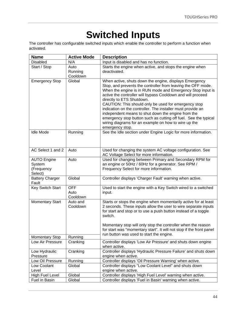
Switched Inputs The controller has configurable switched inputs which enable the controller to perform a function when
activated.
Name Active Mode Description Disabled N/A Input is disabled and has no function.
Start / Stop Auto Running Cooldown
Starts the engine when active, and stops the engine when deactivated.
Emergency Stop Global When active, shuts down the engine, displays Emergency Stop, and prevents the controller from leaving the OFF mode. When the engine is in RUN mode and Emergency Stop input is active the controller will bypass Cooldown and will proceed directly to ETS Shutdown. CAUTION: This should only be used for emergency stop indication on the controller. The installer must provide an independent means to shut down the engine from the emergency stop button such as cutting off fuel. See the typical wiring diagrams for an example on how to wire up the emergency stop.
Idle Mode Running See the Idle section under Engine Logic for more information.
AC Select 1 and 2 Auto Used for changing the system AC voltage configuration. See AC Voltage Select for more information.
AUTO Engine System (Frequency Select)
Auto Used for changing between Primary and Secondary RPM for an engine or 50Hz / 60Hz for a generator. See RPM / Frequency Select for more information.
Battery Charger Fault
Global Controller displays 'Charger Fault' warning when active.
Key Switch Start OFF Auto Cooldown
Used to start the engine with a Key Switch wired to a switched input.
Momentary Start Auto and Cooldown
Starts or stops the engine when momentarily active for at least 2 seconds. These inputs allow the user to wire separate inputs for start and stop or to use a push button instead of a toggle switch. Momentary stop will only stop the controller when the reason for start was "momentary start". It will not stop if the front panel run button was used to start the engine.
Momentary Stop Running
Low Air Pressure Cranking Controller displays 'Low Air Pressure' and shuts down engine when active.
Low Hydraulic Pressure
Cranking Controller displays 'Hydraulic Pressure Failure' and shuts down engine when active.
Low Oil Pressure Running Controller displays 'Oil Pressure Warning' when active.
Low Coolant Level
Global Controller displays "Low Coolant Level" and shuts down engine when active.
High Fuel Level Global Controller displays 'High Fuel Level' warning when active.
Fuel in Basin Global Controller displays 'Fuel in Basin' warning when active.

TOUGHSeries PRO
45
Name Active Mode Description Battle Mode After Cranking Controller ignores all warnings and failures when active.
Displays 'Battle Running' when active. If a failure occurs during Battle Mode it is 'latched' and the engine will shutdown on failure when the controller leaves Battle Mode.
Start Inhibit Global Controller ignores all start commands and the engine cannot start when active. Once Start Inhibit becomes inactive, starting is enabled again. If the engine is running, activating this input will shut down the engine.
Speed Increment Auto Running
Allows the operator to increment the engine speed.
Speed Decrement Auto Running
Allows the operator to decrement the engine speed.
Remote Reset Global Allows the controller to be reset from a failure mode. - Momentary action for 3. - 5s in FAILURE mode will place the controller in OFF mode. - Momentary action for 3. - 5s in OFF mode will place the controller in AUTO mode. - Momentary action for 3. - 5s in RUN mode will place the controller in AUTO mode. Cool-down is skipped.
ECM Preheat (ECM Preheat Signal)
Cranking (during the Preheat countdown only)
Controls preheating using a switched input. See switched Input in the Preheat Mode section.

TOUGHSeries PRO
46
Switched Outputs
The controller is equipped with switched outputs that can be configured to activate under certain
conditions. When activated, the switched outputs are switched to battery voltage to drive the associated
loads when active. The following items are the available functions for switched outputs.
Engine Control
Setting Active Mode Description Fuel Cranking
Running Active during cranking and running to supply fuel to engine.
Crank Cranking Active during cranking to start the engine.
Pull Coil Cranking See Pull and Hold Coil section for more information.
ETS Shutdown ETS Timer Active during Energize to Stop timer.
After Warmup Running Active following warmup period.
Voltage Regulator Running Active when engine is starting/running and is not in Idle Mode.
System in Idle Idle Mode Active when Idle Mode switched input is active.
System in Battle Battle Mode Active when Battle Mode switched input is active.
Programmable Output Global Active when selected event is active.
System Running
Setting Active Mode Description System in Off Off Mode Active when the controller is in OFF mode.
System in Auto Auto Mode Active when the controller is in AUTO mode.
Delay to Start Delay to Start Timer Active when the Delay to Start timer is active.
System in Preheat Preheat Active when system is in Preheat condition.
System in Warmup Warmup Timer Active when system is in Warmup condition.
System in Cooldown Cooldown Timer Active when system is in Cooldown condition.
Normal Run Running Active when system is in Normal Running conditions.
Exerciser Run Exercise Timer Active during the engine exercising cycle.
Low Battery Recharging Run
Battery Recharge Timer Active during the Battery Recharge cycle.
Maintenance Required Global Active when Maintenance timer has expired. If the timer has expired when the controller is in the RUN mode the output does not turn on until the controller enters the OFF or AUTO mode. See the Maintenance section.
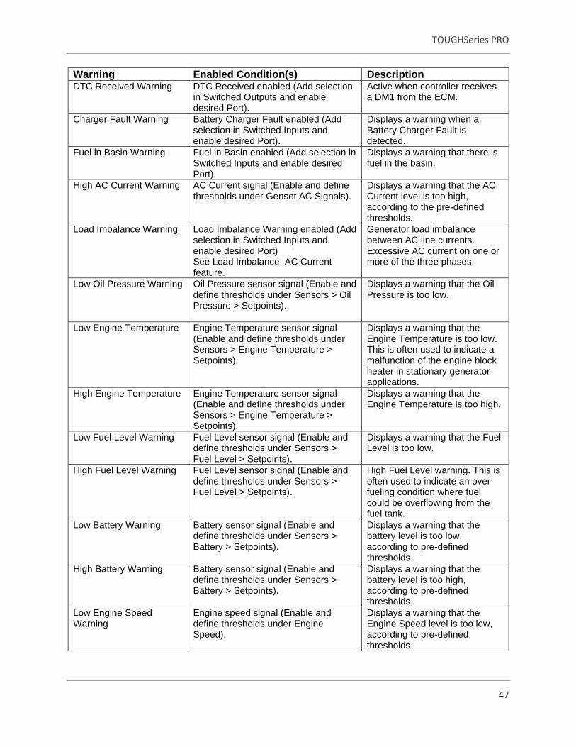
Switched Output-Warnings
Warnings, and consequently failures, occur when certain parameters (fuel level, oil pressure, etc.) are
outside of specified limits. These settings can be configured and observed using the front panel or the
RapidCore Software Configurator.
All warnings and failures are recorded in the Event Log section of the menu.
TOUGHSeries PRO
47
Warning Enabled Condition(s) Description DTC Received Warning DTC Received enabled (Add selection
in Switched Outputs and enable desired Port).
Active when controller receives a DM1 from the ECM.
Charger Fault Warning Battery Charger Fault enabled (Add selection in Switched Inputs and enable desired Port).
Displays a warning when a Battery Charger Fault is detected.
Fuel in Basin Warning Fuel in Basin enabled (Add selection in Switched Inputs and enable desired Port).
Displays a warning that there is fuel in the basin.
High AC Current Warning AC Current signal (Enable and define thresholds under Genset AC Signals).
Displays a warning that the AC Current level is too high, according to the pre-defined thresholds.
Load Imbalance Warning Load Imbalance Warning enabled (Add selection in Switched Inputs and enable desired Port) See Load Imbalance. AC Current feature.
Generator load imbalance between AC line currents. Excessive AC current on one or more of the three phases.
Low Oil Pressure Warning Oil Pressure sensor signal (Enable and define thresholds under Sensors > Oil Pressure > Setpoints).
Displays a warning that the Oil Pressure is too low.
Low Engine Temperature Engine Temperature sensor signal (Enable and define thresholds under Sensors > Engine Temperature > Setpoints).
Displays a warning that the Engine Temperature is too low. This is often used to indicate a malfunction of the engine block heater in stationary generator applications.
High Engine Temperature Engine Temperature sensor signal (Enable and define thresholds under Sensors > Engine Temperature > Setpoints).
Displays a warning that the Engine Temperature is too high.
Low Fuel Level Warning Fuel Level sensor signal (Enable and define thresholds under Sensors > Fuel Level > Setpoints).
Displays a warning that the Fuel Level is too low.
High Fuel Level Warning Fuel Level sensor signal (Enable and define thresholds under Sensors > Fuel Level > Setpoints).
High Fuel Level warning. This is often used to indicate an over fueling condition where fuel could be overflowing from the fuel tank.
Low Battery Warning Battery sensor signal (Enable and define thresholds under Sensors > Battery > Setpoints).
Displays a warning that the battery level is too low, according to pre-defined thresholds.
High Battery Warning Battery sensor signal (Enable and define thresholds under Sensors > Battery > Setpoints).
Displays a warning that the battery level is too high, according to pre-defined thresholds.
Low Engine Speed Warning
Engine speed signal (Enable and define thresholds under Engine Speed).
Displays a warning that the Engine Speed level is too low, according to pre-defined thresholds.

TOUGHSeries PRO
48
Warning Enabled Condition(s) Description High Engine Speed Warning
Engine speed signal (Enable and define thresholds under Engine Speed).
Displays a warning that the Engine Speed level is too high, according to pre-defined thresholds.
Low Frequency Warning Frequency signal (Enable and define thresholds under Genset AC Signal).
Displays a warning that the AC frequency level is too low, according to pre-defined thresholds.
High Frequency Warning Frequency signal (Enable and define thresholds under Genset AC Signal).
Displays a warning that the AC frequency level is too high, according to pre-defined thresholds.
Low AC Voltage Warning AC Voltage signal (Enable and define thresholds under Genset AC Signal).
Displays a warning that the AC Voltage level is too low, according to pre-defined thresholds.
High AC Voltage Warning AC Voltage signal (Enable and define thresholds under Genset AC Signal).
Displays a warning that the AC Voltage level is too high, according to pre-defined thresholds.
Switched Output-Failures
Failures are conditions that cause the controller to shutdown to prevent damage to the engine or generator, or harm to operators. These are conditions that can be enabled or disabled when the operator configures the various settings in the controller.
Figure 18 illustrates what the operator will see from a failure state.
Figure 18: Failure State
TOUGHSeries PRO
49
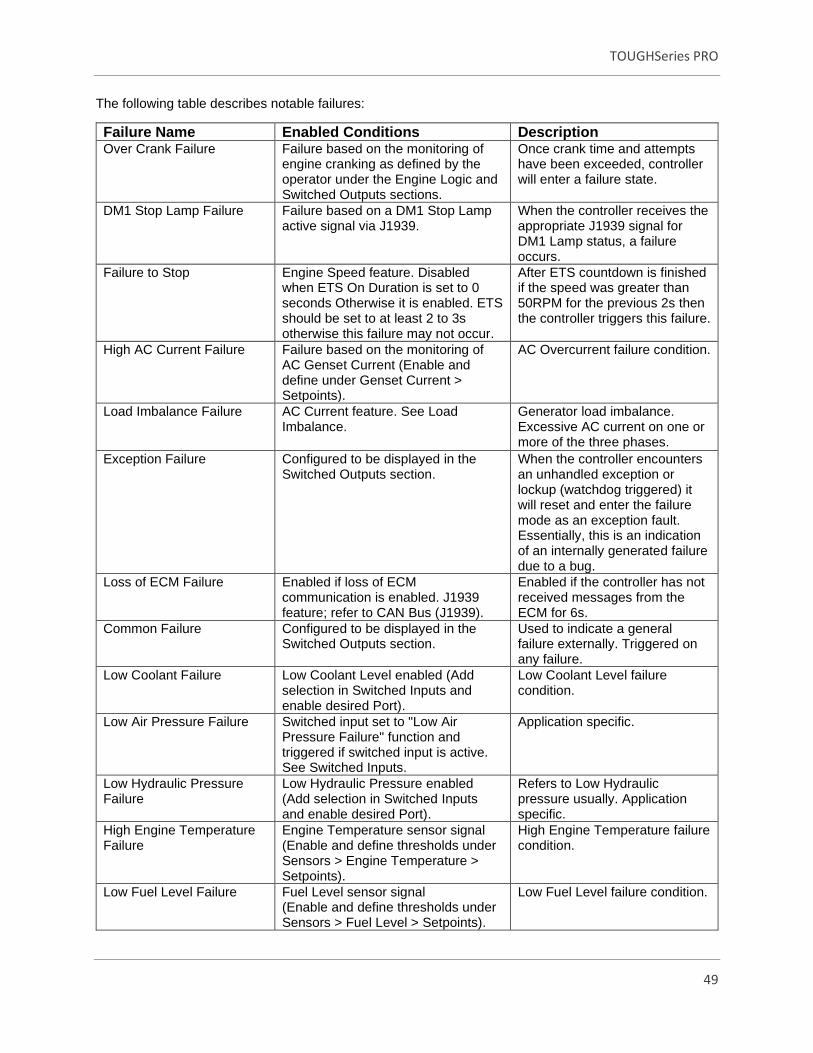
The following table describes notable failures:
Failure Name Enabled Conditions Description Over Crank Failure Failure based on the monitoring of
engine cranking as defined by the operator under the Engine Logic and Switched Outputs sections.
Once crank time and attempts have been exceeded, controller will enter a failure state.
DM1 Stop Lamp Failure Failure based on a DM1 Stop Lamp active signal via J1939.
When the controller receives the appropriate J1939 signal for DM1 Lamp status, a failure occurs.
Failure to Stop Engine Speed feature. Disabled when ETS On Duration is set to 0 seconds Otherwise it is enabled. ETS should be set to at least 2 to 3s otherwise this failure may not occur.
After ETS countdown is finished if the speed was greater than 50RPM for the previous 2s then the controller triggers this failure.
High AC Current Failure Failure based on the monitoring of AC Genset Current (Enable and define under Genset Current > Setpoints).
AC Overcurrent failure condition.
Load Imbalance Failure AC Current feature. See Load Imbalance.
Generator load imbalance. Excessive AC current on one or more of the three phases.
Exception Failure Configured to be displayed in the Switched Outputs section.
When the controller encounters an unhandled exception or lockup (watchdog triggered) it will reset and enter the failure mode as an exception fault. Essentially, this is an indication of an internally generated failure due to a bug.
Loss of ECM Failure Enabled if loss of ECM communication is enabled. J1939 feature; refer to CAN Bus (J1939).
Enabled if the controller has not received messages from the ECM for 6s.
Common Failure Configured to be displayed in the Switched Outputs section.
Used to indicate a general failure externally. Triggered on any failure.
Low Coolant Failure Low Coolant Level enabled (Add selection in Switched Inputs and enable desired Port).
Low Coolant Level failure condition.
Low Air Pressure Failure Switched input set to "Low Air Pressure Failure" function and triggered if switched input is active. See Switched Inputs.
Application specific.
Low Hydraulic Pressure Failure
Low Hydraulic Pressure enabled (Add selection in Switched Inputs and enable desired Port).
Refers to Low Hydraulic pressure usually. Application specific.
High Engine Temperature Failure
Engine Temperature sensor signal (Enable and define thresholds under Sensors > Engine Temperature > Setpoints).
High Engine Temperature failure condition.
Low Fuel Level Failure Fuel Level sensor signal (Enable and define thresholds under Sensors > Fuel Level > Setpoints).
Low Fuel Level failure condition.

TOUGHSeries PRO
50
Failure Name Enabled Conditions Description Low Oil Pressure Failure Oil Pressure sensor signal
(Enable and define thresholds under Sensors > Oil Pressure > Setpoints).
Low Oil Pressure failure condition.
Low Battery Voltage Failure Battery sensor signal (Enable and define under Sensors > Battery > Setpoints).
High Battery failure condition.
High Battery Voltage Failure
Battery sensor signal (Enable and define under Sensors > Battery > Setpoints).
High Battery failure condition.
Low Speed Failure Speed sensor signal (Enable and define thresholds under Sensors > Engine Speed > Speed Settings and Setpoints).
Under Speed failure condition.
High Speed Failure Speed sensor signal (Enable and define thresholds under Sensors > Engine Speed > Speed Settings and Setpoints).
Over Speed failure condition.
Low Frequency Failure Failure based on the monitoring of AC Genset Frequency (Enable and define under Genset Frequency > Setpoints).
Under Frequency failure condition.
High Frequency Failure Failure based on the monitoring of AC Genset Frequency (Enable and define under Genset Frequency > Setpoints).
Over Frequency failure condition.
Low AC Voltage Failure Failure based on the monitoring of AC Genset Voltage (Enable and define under Genset Voltage > Setpoints).
AC Under Voltage failure condition.
High AC Voltage Failure Failure based on the monitoring of AC Genset Voltage (Enable and define under Genset Voltage > Setpoints).
AC Over Voltage failure condition.
Switched Output - Other Functions
Other Functions Condition Description Auto Idle Warm-up, Cooldown Active when the warm-up or
cooldown idle is active. See Warm-up Idle and Cooldown Idle in Engine Logic. This does to react to the Idle switched input.
Dummy Load Running Output is controlled by the dummy load feature.

TOUGHSeries PRO
51
Other Functions Condition Description Genset Disable Global Disables the generator during a
stationary Regen on Kubota engines (see Aftertreatment in the J1939 User Manual) or also during an engine IDLE condition from the IDLE switched input. Automatic idle is ignored. If the generator voltage is not below the under voltage setpoint in 10s, the controller will shut down the engine on "Generator Disable Failure."
Current Breaker Trip Running Output is controlled by the Over Current Failure or IDMT features and by the Load Imbalance feature.
TSC1 Speed Increment Running The controller communicates with the ECM of an electronic engine to adjust its speed by broadcasting the TSC1 command. Refer to the J1939 Manual for more information.
TSC1 Speed Decrement Running
Force Regeneration User Controlled When user triggers a Force Regeneration, output is active for 20 seconds then switches off.
Regeneration Inhibit User Controlled When user triggers a Regeneration Inhibit, output is active for 20 seconds then switches off.
DEF Fluid Pump Running Active when DEF Fluid Level falls below the DEF Low Level and stays active until the level rises above the DEF High Level. See CAN Bus (J1939) section for more information.
Transducer Power Global This is the "Start" and "Stop" transducer setting
User Defined Signals Condition Description Defined Event 1 - 8 Global Application specific, the operator
defines the event as a trigger signal during customizing various Switched Input Events.
Auxiliary Sensor 1 – 10 Trigger
Global Application specific, the operator selects a trigger signal after customizing the Auxiliary Sensor Trigger.
Virtual Auxiliary Sensor 1 – 5 Trigger
Global Application specific, the operator selects a trigger signal after customizing the Virtual Auxiliary Sensor Trigger.

TOUGHSeries PRO
52
User Defined Signals Condition Description Remote Input 1 - 8 Global Writing a single register through
Modbus will activate the Remote Input which will then activate the assigned Switched Output port.
Logic Defined Signals Condition Description OR Signal 1 – 4 Global Common events defined by logic
assigned to engine conditions. AND Signal 1 - 4 Global
*Common AND Signal: All events must be active for the Switched Output to respond and indicate activity.
*Common OR Signal: Either one of the events, NOT all must be active for the Switched Output to
respond.
Programmable Output
The Programmable Output is a Switched Output that is configurable for certain applications.
Setting Active Mode Description Low Battery During Cranking Cranking Active when low battery voltage
threshold is met during cranking.
Fuel Type Global Active when Fuel Type 2 is selected.

TOUGHSeries PRO
53
Engine Speed
Use the following settings' configurations to allow the controller to read and interpret speed sensing data.
Setting Range Description System 50Hz
60Hz (Default) Auto Selection
Used for changing between Primary and Secondary rpm for an engine or 50Hz / 60Hz for a generator.
Signal Source J1939 Bus Magnetic Pickup Generator Voltage (Default) TACH Signal
Source selection for the engine speed signal. J1939 -- Engine speed is obtained over the engine CAN communication bus. Genset Voltage -- The AC Voltage connector phase A is used for engine speed. Magnetic Pickup/TACH Signal -- A magnetic pickup, alternator output, function generator, tachometer or the distributor signal can be used to sense speed. Must use J1 pins 34 and 35. If using a distributer, a filter is often required. Contact DynaGen for more information on using a distributor signal.
Speed Settings
Use the following settings' configurations to allow the controller to read and interpret RPM, and flywheel
teeth.
Setting Range Description Rated RPM 500 - 4000rpm
(Default 1800rpm) Speed at which the engine runs under normal operating conditions. Warning and failure setpoints are calculated from this setting.
Idle RPM 500 - 4000rpm (Default 900rpm)
Speed at which the engine runs when it is idling.
Tooth Count 0.1– 600 (Default 110)
Applies when Signal Source is set to Magnetic Pickup or TACH Signal. Number of teeth on the flywheel. If the number of teeth is unknown the following formula can be used. A multimeter must be used to measure the AC frequency in Hertz (ƒ below) from the magnetic pickup. The speed in rpm’s (v below) must be known.
Tooth Count = (f * 60) / v
When selecting TACH signal, convert the number of teeth according to the distributor poles.

TOUGHSeries PRO
54
Engine Speed Setpoints
Use the following settings' configurations to select the desired speed warnings and failures, this will
prevent possible damage to the engine or generator.
Setting Range Description Under Speed Warning 500 - 4000rpm (Default
1700rpm) Reading at which a warning occurs.
Under Speed Failure 500 - 4000rpm (Default 1600rpm)
Reading at which a failure occurs.
Over Speed Warning 500 - 4000rpm (Default 1900rpm)
Reading at which a warning occurs.
Over Speed Failure
500 - 4000rpm (Default 2000rpm)
A over speed failure is triggered if the speed is above this threshold for 4 seconds
ECM Speed Control Modes
Manual Start
When the user starts the engine from the front panel run button or key switch start input the controller will
refer to the settings defined under this profile.
Setting Range Description Initial RPM Set Rated Speed (Default)
Idle Speed Aux Speed Auto Ramping
The speed profile or set point the controller will go to upon start-up.
• Rated Speed: The controller will go to the set rated speed.
• Idle Speed: The controller will go to the set idle speed.
• Aux Speed: The controller will look at the designated Aux sensor as outlined in TSC1 speed settings (default is Aux 1) and go to whatever speed it is presently reading from that aux if setup.
• Auto Ramping: Upon start-up the unit will go through the defined ramping profile as set in Auto Ramping Setup.
RPM Adjust Source Disable (Default) Local Remote Both Loop Aux
The RPM can be adjusted when selected by the following.
• Local: User can increase/decrease speed from front panel rabbit/turtle buttons.
• Remote: User can use switched inputs, Modbus for remote speed control.
• Both: User can use both front panel and remote speed inputs for speed control.

TOUGHSeries PRO
55
Setting Range Description
• Loop: Speed will automatically adjust based off the settings defined in closed loop control.
• Aux: Speed control will be based off the desired Aux input (default Aux 1) Users must be aware of the position/output signal of their throttle control device upon start-up.
Limit Modes Min/Max Speed (Default) Speed Bias (+/-)
The speed control rpm thresholds.
• Min/Max Speed: As defined in the MAX and MIN RPM settings under TSC1 Speed Settings.
• Speed Bias: As defined in the Speed Bias settings under TSC1 and the Rated RPM under Speed Settings.
Remote Start
When the user starts the engine from a remote start contact or auto-start condition. The parameters
defining this control profile are the same as those defining Manual Start.
Setting Range Description Initial RPM Set Rated Speed (Default)
Idle Speed Aux Speed Auto Ramping
The speed profile or set point the controller will go to upon start-up.
• Rated Speed: The controller will go to the set rated speed.
• Idle Speed: The controller will go to the set idle speed.
• Aux Speed: The controller will look at the designated Aux sensor as outlined in TSC1 speed settings (default is Aux 1) and go to whatever speed it is presently reading from that aux if setup.
• Auto Ramping: Upon start-up the unit will go through the defined ramping profile as set in AUTO Ramping Setup.
RPM Adjust Source Disable (Default) Local Remote Both Loop Aux
The RPM can be adjusted when selected by the following.
• Local: User can increase/decrease speed from front panel rabbit/turtle buttons.
• Remote: User can use switched inputs, Modbus, or J1939 for remote speed control.
• Both: User can use both front panel and remote speed inputs for speed control.
• Loop: Speed will automatically adjust based off the settings defined in closed loop control.

TOUGHSeries PRO
56
Setting Range Description
• Aux: Speed control will be based off the desired Aux input (default aux 1) *Users must be aware of the position/output signal of their throttle control device upon start-up. *
Limit Modes Min/Max Speed (Default) Speed Bias (+/-)
The speed control rpm thresholds.
• Min/Max Speed: As defined in the MAX and MIN RPM settings under TSC1 Speed Settings.
• Speed Bias: As defined in the Speed Bias settings under TSC1 and the Rated RPM under Speed Settings.
TSC1 Speed Settings
The settings below affect Torque Speed Control and the J1939 message, as well as the active actuator
position. TSC1 can be monitored by using a software compatible with J1939 communication.
Setting Range Description Aux Speed Aux 1-10 (Default Aux 1) Auxiliary sensor selection. Only active when
selected as RPM Adjustment Source and/or Initial RPM set in ECM Speed Control Modes > Remote or Manual Start.
Speed Bias (+/-) 5rpm – 600rpm (Default 100rpm)
The minimum or maximum rpm that the engine speed can be adjusted around the rated rpm. Example: Rated rpm is 1800 and Speed Bias is 150. The minimum rpm will be 1650 and maximum rpm will be 1950. Only valid when the correct limit method is chosen.
Bump Speed 1rpm – 500rpm (Default 300rpm)
The RPM change per increment/decrement request signal.
RPM/Sec 10rpm/s – 300rpm/s (Default 200rpm/s)
Refer to the J1939 Reference Manual for information about this setting.
MIN RPM
500rpm – 4000rpm (Default 600rpm)
The minimum rpm that can be set using speed control. Only valid when the correct Limit Method is chosen.
MAX RPM 500rpm – 4000rpm (Default 4000rpm)
The maximum RPM that can be set using speed control. Only valid when the correct Limit Method is chosen.

TOUGHSeries PRO
57
Auto Ramping Setup
Use the following settings' configurations to allow the controller to read and interpret Auto Ramping
Setup. It is only active when selected under Initial RPM Set in ECM Speed Control Modes > Remote or
Manual Start.
Setting Range Description Ramping Goal 500rpm – 4000rpm
(Default 1800rpm) Defines the final RPM that the engine will be ramping to reach.
Intermediate 500rpm – 4000rpm (Default 1200rpm)
Defines the intermediate RPM that the engine will reach before continuing to the goal.
Idle to Intermediate Time
1s - 300s (Default 60s) Defines the amount of time that the engine will take to ramp from the idle speed to intermediate speed.
Intermediate Time 1s - 300s (Default 100s) Defines the amount of time that the engine will remain at intermediate speed during ramping.
Intermediate to Goal Time
1s - 300s (Default 100s) Defines the amount of time that the engine will take to ramp from the intermediate speed to goal speed.
Goal to Idle Time 1s - 300s (Default 60s) Defines the amount of time that the engine will take to ramp from the goal speed back to idle speed.
NOTE: When using J1939 or Genset Voltage as a signal source, connections to the speed sensing
terminals are not required.
NOTE: Speed is monitored at the start of cranking. If there is speed detected above the crank disconnect
setting then cranking and idle is skipped. The speed is not monitored during delay-to-start or preheat as
this provides some degree of protection against false signals due to noise. The fuel input is turned on at
the start of preheat and often powers external equipment that can cause noise.
Front Panel Speed Control
The operator is able to adjust the speed of the engine by using the controller's front panel. This section
describes the methods available for implementing speed control, the settings and parameters to be used,
as well as the necessary instructions allowing the operator to control the speed.
Setting Description Front Panel Speed Control using J1939 TSC1
The controller can instruct the ECM of an electronic engine to adjust its speed by broadcasting the TSC1 command. Refer to the J1939 Manual for more information

TOUGHSeries PRO
58
Setting Description Front Panel Speed Control using Switched Outputs Advanced Setting > Switch Output > Other Functions > Press Menu button until Tsc1 Speed Increment/decrement settings appear.
The controller can instruct the ECM of an electronic engine to adjust its speed by using the TSC1 speed increment/decrement switched outputs, on the controller set to rpm increment and rpm decrement to interface with digital inputs on the ECM. When the speed is changed, the corresponding switched output will be on for one second each time increment or decrement is pressed. This function also has Electronic Governor systems with increment/decrement contacts such as the Woodward L series Governors. See the rest of this section for more information.
Aux Speed Control The auxiliary sensor is used to determine setpoint speed. The speed is adjusted with the TSC1 J1939 command. Refer to the J1939 Manual for more information.
Speed Increment/Decrement Front Panel Buttons (Rabbit/Turtle)
The controller features a speed increment and a speed decrement button, with industry standard rabbit and turtle symbols, respectively. To Configure via the controller, enter Engine Speed > System Speed Mode > Manual Start.
Closed Loop Control
The Process Control feature has two different control methods: Maintain In and Maintain Out. The
Maintain In option maintains a reservoir level by controlling the flow of fluid into the reservoir. The
Maintain Out option maintains a reservoir level by controlling the flow of fluid from the reservoir. It does
this by regulation the speed of the engine over the J1939 CAN bus.
The controller reads the sensor value from selected Auxiliary Sensor input, compares the input value set-
point, and then, based on an algorithm, increments or decrements the speed (RPM) by an amount
proportional to the difference between the setpoint and actual level to maintain the desired set-point
outside of the dead-band area. Control pauses inside the dead-band area. If the sensor input goes
beyond a minimum or maximum value, the RPM will be maintained at a minimum or maximum value.
The algorithm is a fuzzy logic type control with a dead band and a minimum / maximum saturation. The
user sets the aggressiveness of the control with the Gain setting and the response time of the control with
the Delay setting.
Setting Range Description Control Type Disable (Default)
Maintain In Maintain Out
Maintain In controls the level when pumping fluid into a reservoir. Maintain Out controls the level while pumping fluid out of the reservoir.
Signal Source Auxiliary Sensor 1 – 10 (Default Auxiliary Sensor 1)
The Auxiliary Sensor Input function that is providing feedback on the reservoir level.
Delay 0.1s - 30s (Default 5s) The sampling time of the control algorithm.

TOUGHSeries PRO
59
Setting Range Description Gain 1 – 30 (Default 19) The amount to increment or decrement the
RPM proportionate to the sensed value outside of the dead-band.
Setpoints Maintain In 1 – 900 (Default 300) The level set-point to attempt to maintain. Only
applies if System is set to In-Keep.
Maintain Out 1 – 900 (Default 500) The level set-point to attempt to maintain. Only applies if System is set to Out-Keep.
High Deadband 1 – 30 (Default 3) The high limit of the dead-band.
Low Deadband 1 – 30 (Default 3) The low limit of the dead-band.
Thresholds High Limit 1 – 900 (Default 700) The high saturation. The maximum level at
which the rpm control is fixed.
Low Limit 1 – 900 (Default 100) The low saturation. The minimum level at which the rpm control is fixed.
Setting Range Description
Max Limit RPM 500rpm – 4000rpm (Default 3200rpm)
The fixed rpm that should be used when the level rises above the High Limit.
Low Limit RPM 500rpm – 4000rpm (Default 1000rpm)
The fixed rpm that should be used when the level falls below the Low Limit.

TOUGHSeries PRO
60
Sensors
The TOUGHseries PRO has 10 sensor inputs which can be connected to a variety of different
sensors/switches depending on the input. See the Terminal Descriptions section for more information
regarding the sensor types supported.
To configure the behaviour of these sensor inputs the user assigns the sensor input to one of the
following:
· Engine Temperature
· Oil Pressure
· Fuel Level
· Auxiliary Sensor 1 - 10
The Engine Temperature, Oil Pressure, and Fuel Level functions are fixed in functionality but assigned by
the operator. The Auxiliary sensors can be configured to perform specific shutdowns or special functions
(Example: Starting engine on low temperature).
System Battery
Use the following settings' configurations to allow the controller to read and interpret the battery voltage
level. Figure 19 illustrates the logic flow for the recharge functionality.
Setting Range Description Auto-Start Level Disable (Default)
5V - 50V Voltage level at which the controller starts the engine to recharge the battery.
Recharge Pre-Alarm 1 – 30min (Default 5 min)
Amount of time to display a warning before starting the engine.
Recharge Run Duration 10 – 900min (Default 30 min)
Amount of time to run the engine.
Setpoints
Setting Range Description Low Warning Disable
5V – 50V (Default 9V) Reading at which a warning occurs.
Low Failure Disable 5V – 50V (Default 8V)
Reading at which a failure occurs.
High Warning Disable 5V – 50V (Default 27V)
Reading at which a warning occurs.
High Failure Disable (Default) 5V – 50V (Default 28V)
Reading at which a failure occurs.
Low Battery During Cranking
5V – 50V (Default 9V) Screen displays a 'Low Voltage During Cranking' warning if voltage drops below this level during cranking.

TOUGHSeries PRO
61
NOTE: When the engine is running, the battery voltage will equal the alternator charging voltage. The
actual open circuit battery voltage may be lower than displayed.
Figure 19: Battery Recharge Functionality
Engine Temperature
Use the following settings' configurations to allow the controller to read and interpret data from the engine
temperature sensor or switch.
Setting Range Description Signal Source Sensor Input 1 (Default)
Disable Sensor Input 1 – 10 J1939 Bus
The sensor input pin where the engine temperature switch or sender is attached. *Engine temperature is obtained from the engine controller (ECM) using the CANbus communication port and J1939 protocol.
Sensor Type DAT DAH* (Default) VDO 250F* Custom sender**
Select the sender that is connected to the Signal Source above. If using a switch, select the action that should occur when the switch is active. *These are preprogrammed into the controller and cannot be changed. - DAT DAH supports all Datcon type DAH (high range) temperature sensors such as 02022-00. - VDO 250F supports the VDO 323-420 or equivalent temperature sensor. **A custom table can be created using the RapidCore Configuration Software. The text (custom sender) will be replaced with the custom text you choose when creating the sender.

TOUGHSeries PRO
62
Setting Range Description Trim Offset -50.0 ~ 50.0 °F
(Default 0 °F) Calibrate a sensor by using the offset to correct errors. Only applies if Sensor Type has been set to a sender.
Engine Temp. Custom Sender Table
Name: Custom Text Input Type: Resistance Voltage 4-20mA Unit Type: Temperature Sender: Custom Table
Custom Sender configuration options. The user can create a sender table that applies to the application.
Setpoints Bypass Time 1 ~ 30 seconds
(Default 10s) Amount of time to bypass warnings and failures after engine has started.
Low Warning Disabled 5 ~ 399°F (Default 50°F) (-15 ~ 204°C)
Reading at which a "Low Engine Temp" warning occurs. Displays 'Low Engine Temp' on the screen. Only applies if Sensor Type has been set to a sender. Monitored globally including OFF and AUTO.
High Warning Disabled 5 ~ 399°F (Default 200°F) (-15 ~ 204°C)
Reading at which a "High Engine Temp" warning occurs. Only applies if Sensor Type has been set to a sender. Only monitored in the RUN mode.
High Failure Disabled 5 ~ 399°F (Default 220°F) (-15 ~ 204°C)
Reading at which a "High Engine Temp" failure occurs. Only applies if Sensor Type has been set to a sender. Only monitored in the RUN mode.
Oil Pressure
Use the following settings' configurations to allow the controller to read and interpret data from the oil
pressure sensor or switch.
Setting Range Description Signal Source Sensor Input 3 (Default)
Disable Sensor Input 1 – 10 J1939 Bus
The sensor input pin where the oil pressure switch or sender is attached. *Oil pressure is obtained from the engine controller (ECM) using the CANbus communication port and J1939 protocol.
Sensor Type DAT 100P/R240* (Default) VDO 150P/R180* Custom sender**
Select the sender that is connected to the Signal Source above. If using a switch, select the action that should occur when the switch is active. *These are preprogrammed into the controller and cannot be changed. - DAT 100P/R240 supports the Stewart - Warner 279B-F and Datcon 2505-00 sender tables. - VDO 150P/R180 supports the VDO 360-004 oil pressure sender. **A custom table created using the RapidCore Configuration Software. The text (custom

TOUGHSeries PRO
63
Setting Range Description sender) will be replaced with the custom text you choose when creating the sender.
Trim Offset -50.0 ~ 50.0 psi (Default 0 psi) (-344.7 ~ 344.7kPa)
Calibrate a sensor by using the offset to correct errors. Only applies if Sensor Type has been set to a sender.
Oil Pressure Custom Sender
Name: Custom Text Input Type: Resistance Voltage 4-20mA Unit Type: Pressure Sender: Custom Table
Custom Sender configuration options. The user can create a sender table that applies to the application.
Setpoints
Settings Range Description Bypass Time 1 ~ 30 seconds (Default 10s) Amount of time to bypass warnings and failures
after engine has started.
Low Warning Disabled 1 ~ 699.9 psi (Default 20 psi) (7 ~ 4826.3301 kPa)
Reading at which a "Low Oil Pressure" warning occurs. Only applies if Sensor Type has been set to a sender.
Low Failure Disabled 1 ~ 699.9 psi (Default 15 psi) (7 ~ 4826.3301 kPa)
Reading at which a "Low Oil Pressure" failure occurs. Only applies if Sensor Type has been set to a sender.
Fuel Level
Use the following settings' configurations to allow the controller to read and interpret data from the fuel
level sensor.
Setting Range Description Signal Source Sensor Input 4 (Default)
Disable Sensor Input 1 – 10
The sensor input pin where the fuel level switch or sender is attached.
Sensor Type DAT R/33-240* (Default) VDO R/0-180* Custom sender**
Select the sender that is connected to the Signal Source above. If using a switch, select the action that should occur when the switch is active. *These are preprogrammed into the controller and cannot be changed. - DAT R33-240 supports a DATCON fuel level sensor of the range 33 Ohms to 180 Ohms - VDO R/0-180 supports a VDO fuel level sensor of the range 0 Ohms to 180 Ohms **A custom table created using the RapidCore Configuration Software. The text (custom sender) will be replaced with the custom text you choose when creating the sender.

TOUGHSeries PRO
64
Setting Range Description Trim Offset -50.0 ~ 50.0% (Default 0%) Calibrate a sensor by using the offset to correct
errors. Only applies if Sensor Type has been set to a sender.
Fuel Level Custom Sender
Name: Custom Text Input Type: Resistance Voltage 4-20mA Unit Type: Level Sender: Custom Table
Custom Sender configuration options. The user can create a sender table that applies to the application.
Setpoints Bypass Time 1 ~ 30 seconds (Default 10s) Amount of time to bypass warnings and failures
after engine has started.
Low Warning Disabled 1 ~ 100% (Default 20%)
Reading at which a "Low Fuel Level" warning occurs. Only applies if Sensor Type has been set to a sender. Only monitored in the RUN mode.
Low Failure Disabled 1 ~ 100% (Default 15%)
Reading at which a "Low Fuel Level" failure occurs. Only applies if Sensor Type has been set to a sender. Only monitored in the RUN mode.
High Warning Disabled 1 ~ 100% (Default 96%)
Reading at which a "High Fuel Level" warning occurs. Displays 'High Fuel Level' on the screen. Only applies if Sensor Type has been set to a sender. Monitored globally including OFF and AUTO.
Auxiliary Sensors
The TOUGHSeries Pro has ten auxiliary sensor inputs that are used for supporting custom sensors and
triggering actions based on the sensor values.
You must use the RapidCore Configuration Software to program a custom sender table to the controller
for the auxiliary sensor(s) that will be used. Otherwise, an undefined sensor will appear in the front panel
menu system. Once a sender table is programmed to the controller all the other settings can be adjusted
from the front panel of the controller.
Scroll through each Auxiliary Configuration by pressing the menu/navigational button below the LCD.
Setting Range Description Display Disable (Default)
Hidden Auto Engage Running
Determines when the sensor’s value is displayed on the screen, during either auto mode, engage or running.
Name Custom Text Defines the sensor name to be displayed.
Sender Table Type
Custom Table (Default) Datcon DAH VDO 250F
The sender resistance / value curve must be programmed from the RapidCore Configuration Software even if the port is being

TOUGHSeries PRO
65
Setting Range Description Datcon 100P/R240 VDO 150P/R180 Datcon R/33-240 VDO R/0-180 TF1 115F/R240 TF2 231F/R240 TP1 200P/R240 TP2 100P/R240
overloaded. This tells the controller how to interpret the signal from the port. No front panel configuration is allowed until the sender curve is programmed to the controller.
Trim Offset -500 ~ 500 units. (Default 0) The units depend on the unit type of the programmed sender table -- 0F, psi, %, V, A.
This displays a fixed offset to the actual sensor reading. The operator can calibrate a sensor by using the offset to correct errors.
Bypass Time 0.1 – 30s (Default 5s).
The period of time a sensor will be ignored after entering the active state, according to the configured sensor.
Auxiliary Sensor Custom Sender
Name: Custom Text Input Type: Resistance Voltage 4-20mA Unit Type: Temperature Level Pressure Voltage Current Length Speed Sender: Custom Table
Custom Sender configuration options. The user can create a sender table that applies to the application.
Auxiliary Sensor Configuration
Start Configuration
Name: Custom Text Is: Greater Than Less Than (Default) Constant: Disable (Default)
0.1 – 6000 More Than: 0.1 – 3600s (Default 3s) Run Duration: 1 – 900min (Default 60min)
User configurable engine start control based on logic relating to sensor parameters and comparison.
“More than” is the period of time that a sensor is greater than or less than a given set point for it to trigger a Start command. “More Than” time will not begin until the Auxiliary Sensor “ByPass Time” has completed.
Stop Configuration
Name: Custom Text Is: Greater Than Less Than Constant: Disable (Default)
0.1 – 6000 More Than: 0.1 – 3600s (Default 3s)
User configurable engine stop control based on logic relating to sensor parameters and comparison. “More than” is the period of time that a sensor is greater than or less than a given set point for it to trigger a Stop command. “More Than” time will not begin until the Auxiliary Sensor “ByPass Time” has completed.
Warning Configuration
Warning Delay: 0.1 – 3600s (Default 3s) Low Warning Name: Custom Text Value: Disable (Default)
User configurable warning based on the logic relating to sensor parameters and comparison. Warning Delay is the period of time a sensor must be active before the configured warning

TOUGHSeries PRO
66
Setting Range Description 0.1 – 6000
High Warning Name: Custom Text Value: Disable (Default)
0.1 – 6000 Active Modes: OFF AUTO Engage Running Cooldown Shutdown
is activated. The Warning Delay time will not begin until the Auxiliary Sensor “ByPass Time” has completed. Active Modes refer to the engine states in which the configured warning condition can occur.
Failure Configuration
Failure Delay: 0.1 – 3600s (Default 3s) Low Failure Name: Custom Text Value: Disable (Default)
0.1 – 6000 High Failure Name: Custom Text Value: Disable (Default)
0.1 – 6000 Active Modes: OFF AUTO Engage Running Cooldown Shutdown Failure
User configurable failure based on the logic relating to sensor parameters and comparison. Failure Delay is the period of time a sensor must be active before the configured failure is activated. The Failure Delay time will not begin until the Auxiliary Sensor “ByPass Time” has completed. Active Modes refer to the engine states in which the configured failure condition can occur.
Trigger Configuration
Name: Custom Text If: Greater than Less Than (Default) Constant: Disable (Default)
0.1 – 6000 More Than: 0.1 – 3600s (Default 3s) Hysteresis: Disable (Default) 0.1 – 6000 *Special: Inhibit Start Hold Cooldown Active Modes: OFF AUTO Engage Running Cooldown Shutdown
User configurable trigger based on the logic relating to sensor parameters and comparison. “More than” is the period of time that a sensor is greater than or less than a given set point for it to trigger the “Special” or signal command. “More Than” time will not begin until the Auxiliary Sensor “ByPass Time” has completed.
* Inhibit Start: If active and the controller is in Off or Auto mode it will prevent the engine from starting. If
Active and the controller is in the Engage, Running or Cooldown states, the controller will shutdown and
enter Auto mode bypassing the cooldown state. *
* Hold Cooldown: If active while in the cooldown state, the controller will not shutdown under normal
operation. Activating start inhibit, emergency stop, or a failure will cause the engine to stop. *

TOUGHSeries PRO
67
Temperature Fault Monitoring Example
In this example, a sensor is monitoring the temperature of an engine block. After the Auxiliary Sensor is
programmed in the TOUGHseries Pro unit the user can choose either an Auxiliary warning or failure. The
Auxiliary Configuration allows the user the option to program the warning or failure for greater than or less
than applications. The Auxiliary Trigger Signal 1-10 can be selected as well for the indication using a
switched output.
Figure 20 shows the connection between engine temperature and time. At approximately 13 minutes run
time, the temperature rises above the 275°F warning threshold, activating the warning display. The
engine will continue to run because it has not reached the 350°F failure threshold. At 20 minutes run time,
the temperatures fall below the warning threshold and the warning disappears. The failure will not be
activated until the temperature reaches above 350°F.
Figure 20: Engine Temperature Warnings and Failures

TOUGHSeries PRO
68
Virtual Auxiliary Sensors
The TOUGHSeries Pro has five virtual auxiliary sensor inputs that are assigned to auxiliary sensors for
triggering actions. The Virtual Auxiliary Sensor value is based off of the assigned Auxiliary Sensor value.
Example of a Virtual Auxiliary Sensor:
- Virtual Sensor 1 is sourced to Auxiliary Sensor 1.
- The warning, failure, and trigger values for Virtual Sensor 1 are triggered through the Auxiliary
Sensor 1 value.
Setting Range Description Virtual Auxiliary Sensor Source: Disable (Default)
Auxiliary Sensor 1 – 10 Bypass Time: 0.1 - 30 (Default 5s)
The auxiliary sensor selected will determine the base value for the virtual sensor.
Warning Configuration Warning Delay: 0.1 – 3600s (Default 3s) Low Warning Name: Custom Text Low Warning Value: Disable (Default)
0.1 – 6000 High Warning Name: Custom Text High Warning Value: Disable (Default)
0.1 – 6000 Active Modes: OFF AUTO Engage Running Cooldown Shutdown
User configurable warning. The warning is activated when the assigned auxiliary sensor value drops below/exceeds the configurable value for the virtual sensor. Warning Delay is the period of time a sensor must be active before the configured warning is activated. The Warning Delay time will not begin until the Auxiliary Sensor “ByPass Time” has completed. Active Modes refer to the engine states in which the configured warning condition can occur.
Failure Configuration Failure Delay: 0.1 – 3600s Low Failure Name: Custom Text Value: Disable (Default)
0.1 – 6000 High Failure Name: Custom Text Value: Disable (Default)
0.1 – 6000 Active Modes: OFF AUTO Engage Running Cooldown Shutdown Failure
User configurable failure. The failure is activated when the assigned auxiliary sensor value drops below/exceeds the configurable value for the virtual sensor. Failure Delay is the period of time a sensor must be active before the configured failure is activated. The Failure Delay time will not begin until the Auxiliary Sensor “ByPass Time” has completed. Active Modes refer to the engine states in which the configured failure condition can occur.

TOUGHSeries PRO
69
Setting Range Description Trigger Configuration If: Greater Than
Less Than Constant: Disable (Default) 0.1 – 6000 More Than: Disable (Default)
0.1 – 3600s Hysteresis: Disable (Default)
0.1 – 6000 *Special: Inhibit Start Hold Cooldown Active Modes: OFF AUTO Engage Running Cooldown Shutdown
User configurable trigger. The trigger is activated when the assigned auxiliary sensor value drops below/exceeds the configurable value for the virtual sensor. “More than” is the period of time that a sensor is greater than or less than a given set point for it to trigger the “Special” or signal command. “More Than” time will not begin until the Auxiliary Sensor “ByPass Time” has completed.
* Inhibit Start: If active and the controller is in Off or Auto mode it will prevent the engine from starting. If
Active and the controller is in the Engage, Running or Cooldown states, the controller will shutdown and
enter Auto mode bypassing the cooldown state. *
* Hold Cooldown: If active while in the cooldown state, the controller will not shutdown under normal
operation. Activating start inhibit, emergency stop, or a failure will cause the engine to stop. *

TOUGHSeries PRO
70
Timers & Scheduler
The controller has an internal clock which is used not only to keep time, but to ensure programed events
happen at the correct times. The following sections are used to configure settings associated with timing
functions.
NOTE: The controller has an on-board backup battery to keep time even when main power is not
supplied to the unit. This battery has an unpowered (no main power) lifetime of approximately five years.
Engine Timer Logic
The following settings determine how the controller starts and stops the engine. It gives the user the
functionality to add delays and timers to the sequences. Most of the settings have a switched output
associated with them that must be set in the Switched Outputs settings.
Setting Range Description Delay to Start Disable
1 - 90s (Default 6s) Amount of time to delay the starting of the engine after receiving a command to start.
Delay to Start on Manual Run
Enable (Default) Disable
Determines if the Delay to Start timer is used when the front panel RUN button is used to start the engine.
Preheat Signal Source Preheat Timer (Default) Switched Input J1939
Determines the method used to control enabling the glow plug output. See the Preheat Mode section for more information
Preheat Time Disable 1 - 1200s (Default 8s)
Amount of time the glow plug output is active before cranking the engine. Used on diesel engines to warm the engine before cranking.
Midheat Time Disable (Default) 1 - 90s
Keeps glow plug output turned on while cranking but not during crank rest. Output will turn off upon crank failure, crank success or midheat time expiration.
Postheat Time Disable (Default) 1 - 90s
Amount of time the glow plug output remains on after crank success and the engine is running.
Crank Time 3 - 30s (Default 3s) Amount of time the Crank output is active before going to crank rest. This timer immediately expires upon successful cranking.
Crank Rest Time 3 - 60s (Default 5s) Amount of time to delay between each attempt to start the engine.
Crank Attempts 1 – 12 (Default 3) Number of attempts to start the engine before going to an over crank failure.
Fuel ON While Resting Fuel ON (Default) Fuel OFF
Determines if the fuel output stays on during the crank rest time.
Crank Success RPM 100 – 2000 rpm (Default 660rpm)
Speed at which controller determines the engine has started successfully and turns off the Crank output.
False Start Restart Enable Disable (Default)
Enable false start (engine stall) detection. Determines if the controller will monitor for false starts and attempt a restart. Controller will only

TOUGHSeries PRO
71
Setting Range Description attempt restarting the engine as many times as determined by Crank Attempts.
False Detect Time 3 – 30 Seconds (Default 10s)
If False Start Reset is enabled it will enable this feature. It is the amount of time after crank success to monitor for a false start.
Stall Detection Enable (Default) Disable
When enabled the controller detects when the engine is stalling. A message will appear on the controller indicating a stalling state.
Warmup Time Disable 1 - 1200s (Default 30s)
After successful cranking, engine delays this amount of time before turning on the Warmup output. This allows the engine to warm up before applying any load to it. The output will turn off when the controller enters the Cooldown Delay.
OFF Key Function Cooldown (Default) Shutdown Force Cooldown
The function the OFF key on the front panel performs while engine is running. See the Off-Key Function section for more information.
Cooldown Time Disable 5 - 6000s (Default 30s)
Amount of time to cool down the engine after a stop command has been received. During this time the Warmup output turns off and the Cooldown output turns on. If another start command is received during cool down, the controller will return to running mode.
Energize to Stop Duration
Disable 3 - 300s (Default 3s)
Amount of time the Energize to Stop output is on after the engine has shut down. If controller still detects speed (rpm) after this time expires, it goes to a 'Failed to Stop' failure. Time must be greater than 0 seconds for the Energize to Stop function to work.
Failed to Stop Disable 100-1000 rpm (Default 500rpm)
Rpm over which the controller will consider the engine to have failed to stop.
Warm-up Idle Disable (Default) Warm-up Timer Oil Temperature Engine Temperature
Configurable parameter for warm-up idle. The warmup idle is used to run the engine at a reduced speed at engine start. Can be configured to idle for a set period of time, based on achieving a target oil temperature, or engine temperature in order to warm-up the engine as desired by the operator.
Idle Settings
Setting Range Description Idle Limit 1 - 10s (Default 10s) Idle time limit (for use with Oil Temperature or
Engine Temperature warm-up conditions).
Idle Low Setpoint Temperature
10 - 399°F (Default 32°F)
Low temperature threshold for warm-up idle parameters (for use with Oil Temperature or Engine Temperature warm-up conditions).
Idle High Setpoint Temperature
10 - 399°F (Default 50°F)
High temperature threshold for warm-up idle parameters (for use with Oil Temperature or Engine Temperature warm-up conditions).
Idle Cooldown Enable Disable (Default)
Idle during cooldown conditions.

TOUGHSeries PRO
72
Setting Range Description Start/Stop Switch Input Inhibit
Enable Disable (Default)
Prevent the remote start switch input from starting the engine when the idle switch is active.
Aux Start Idle Inhibit Enable Disable (Default)
Prevent the auxiliary start switch input from starting the engine when the idle switch is active.
Switch Start Idle Inhibit Enable Disable (Default)
Prevent the start switch on a switched input from starting the engine when the idle switch is active.
Idle
The controller ignores under speed, voltage and frequency warnings and failures when active. If using
J1939, the controller will broadcast TSC1 as the Idle Speed parameter found in the Engine Speed
section.
This section explains the general idle functionality.
There are three ways to use idle:
1. Idle Warmup - Automatically enter the idle mode during warmup for a period of time before
going to rated speed. See Warmup Idle.
2. Cool down Idle - Idle automatically during cool down.
3. Idle Switched Input - Idle whenever this switched input is active. See the Idle Mode function
under Switched Inputs.
If the engine is in the IDLE mode because of the Warmup Idle feature, the remote start (start/stop) and
auxiliary sensors AutoStart can still start the engine.
This prevents starting when the Idle switch is active in the AUTO mode. This will also shutdown the
engine if the idle switched input is activated when the controller is in the delay-to-start, preheat, cranking,
and crank reset states. The main purpose is to prevent a remote start if the idle switch was accidentally
left on.

TOUGHSeries PRO
73
Preheat Mode
The controller has the ability to control the length of the preheat time through 3 different methods. The
table below describes each method.
Mode Description
Preheat Timer This mode uses the Preheat Time setting in the Engine Logic menu.
Switched Input This mode uses a switched input set to 'ECM Preheat' to determine when to exit preheat. The preheat time (in Engine Logic) must be set to a minimum of 5 seconds for this input to work. If the switched input is or becomes active when the preheat timer is counting down the controller displays 'ECM Preheating' on the screen after the preheat counter has finished its countdown. Cranking begins when the 'ECM Preheat' switched input is no longer active.
J1939 This mode uses commands sent from the ECM over J1939 to decide when to exit preheat.
OFF Key Function
The OFF button on the front panel of the controller can be configured to function in 3 different ways while
the engine is running. This can be done using the “OFF Key Function” dropdown menu in the Engine
Timer Logic menu of RapidCore Configurator. The table below describes each of these functions.
Function Description Cooldown This function causes the controller to go into
cooldown. Pressing the OFF button for the second time will cause the engine to shut down.
Shutdown This function bypasses Cooldown and causes the engine to shut down.
Force Cooldown This function causes the controller to activate the cooldown process. Pressing the OFF button will have no affect as the controller is forcing the engine to perform a full cool down.
WARNING: If the controller receives a command to start from the remote start, front panel
run button, CAN or MOD bus, or Aux Start while in Cooldown, it will leave the Cooldown
mode and go back to Running mode.

TOUGHSeries PRO
74
Schedulers
Exercise Scheduler
The Exerciser function is used to start and run the engine periodically. When waiting for the Exercise
Scheduler to start the controller MUST be in Auto mode. The following settings configure the Exerciser
function. Figure 22 illustrates this functionality.
Setting Range Description Start Time 12:00AM - 11:45PM Start time for exerciser function.
Pre-alarm 1 – 20 minutes Amount of time to display a warning before starting the engine.
Duration 15 minutes – 15 hours
Amount of time to run the engine.
Stop Time 12:00AM – 11:45PM Stop Time for exerciser function.
Schedule: Daily/Weekly Sunday – Saturday
Configurable frequency of exerciser. Number of days/weeks between each exerciser cycle. This setting is applied to all subsequent exerciser starts after the first start.
Start Date Configurable calendar start date for exerciser runs.
Figure 21: Exerciser Functionality
If the controller is in the OFF mode, if the emergency stop is activated, or if the start inhibit is active then
the exerciser will not run. The event, "Bypass Exerciser", will be logged in the event log and the exerciser
will run again at the next scheduled time as determined by the "Repeat Days" setting.

TOUGHSeries PRO
75
Weekly Scheduler
The weekly scheduler allows multiple unique weekly exercise times to be created.
Setting Range Description Start Time 12:00AM – 11:45PM When the exercise should start on a given day.
At the selected time a one-minute pre-alarm is displayed on the LCD screen. The controller starts after this one-minute period.
Duration 15 minutes - 15 hours Duration of exercise run. Will auto-fill if Stop Time is selected first.
Stop Time 12:00AM – 11:45PM When the exercise should stop on a given day. Will auto-fill if duration is selected first.
Daily/Weekly Sunday - Saturday The day of the week the exercise will take place on.
It is recommended to use the RapidCore Configuration Software to enter the times as this provides a
much more convenient interface especially if daily exercise times are wanted.
Engine Maintenance Schedule
The controller has the ability to count down the time between scheduled maintenance events. Once
maintenance is required, the controller will alert the operator via a warning on the LCD screen and a
switched output (if enabled) wired to a lamp / horn / buzzer. The following settings are used to configure
the maintenance timer.
The Long Time Run counter can be used to shutdown the controller after a very long period of time. This
is useful for remote primary power applications where the user wants to divide run time between two
generators, or when a finite run time is desired without the need for an operator to return for shutdown.
When the countdown expires the controller will shutdown.
Setting Range Description Enable Counter Enable
Disable (Default) Enables or disables the maintenance function. Accessible through the front panel access.
Count Interval 10 – 9000 hours (Default 1000)
Determines the number of hours between required maintenance. A switched output can be configured to turn on once the count interval expires. Accessible through the front panel access.
Long Term Run Enable Disable (Default)
Allows operator to configure their system to use long term run if it applies for the application. Accessible through the Rapidcore Configurator Software.
Run Duration 1 – 5000 hours (Default 60 hours)
The amount of time to run before shutting down. Accessible through the Rapidcore Configurator Software.

TOUGHSeries PRO
76
To determine the amount of time until the next scheduled maintenance, follow these menu steps:
Advanced Setting > Time and Scheduler > Engine Maintenance > Counter Hour
To reset the counter, follow these menu steps:
Advanced Setting > Time and Scheduler > Engine Maintenance > Reset Counter
Maintenance counter is disabled if '----' is displayed. A negative number indicates the amount of time
since maintenance timer expired.
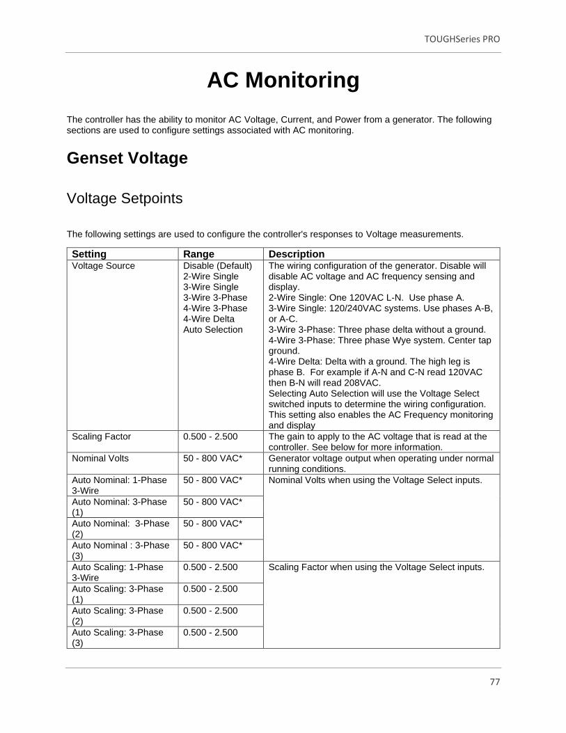
TOUGHSeries PRO
77
AC Monitoring
The controller has the ability to monitor AC Voltage, Current, and Power from a generator. The following sections are used to configure settings associated with AC monitoring.
Genset Voltage
Voltage Setpoints
The following settings are used to configure the controller's responses to Voltage measurements.
Setting Range Description Voltage Source Disable (Default)
2-Wire Single 3-Wire Single 3-Wire 3-Phase 4-Wire 3-Phase 4-Wire Delta Auto Selection
The wiring configuration of the generator. Disable will disable AC voltage and AC frequency sensing and display. 2-Wire Single: One 120VAC L-N. Use phase A. 3-Wire Single: 120/240VAC systems. Use phases A-B, or A-C. 3-Wire 3-Phase: Three phase delta without a ground. 4-Wire 3-Phase: Three phase Wye system. Center tap ground. 4-Wire Delta: Delta with a ground. The high leg is phase B. For example if A-N and C-N read 120VAC then B-N will read 208VAC. Selecting Auto Selection will use the Voltage Select switched inputs to determine the wiring configuration. This setting also enables the AC Frequency monitoring and display
Scaling Factor 0.500 - 2.500 The gain to apply to the AC voltage that is read at the controller. See below for more information.
Nominal Volts 50 - 800 VAC* Generator voltage output when operating under normal running conditions.
Auto Nominal: 1-Phase 3-Wire
50 - 800 VAC* Nominal Volts when using the Voltage Select inputs.
Auto Nominal: 3-Phase (1)
50 - 800 VAC*
Auto Nominal: 3-Phase (2)
50 - 800 VAC*
Auto Nominal : 3-Phase (3)
50 - 800 VAC*
Auto Scaling: 1-Phase 3-Wire
0.500 - 2.500 Scaling Factor when using the Voltage Select inputs.
Auto Scaling: 3-Phase (1)
0.500 - 2.500
Auto Scaling: 3-Phase (2)
0.500 - 2.500
Auto Scaling: 3-Phase (3)
0.500 - 2.500

TOUGHSeries PRO
78
Setting Range Description Single Phase Voltage Sensing
A-C Phase A-B Phase
Configuration setting for 2-wire or 3-wire single phase voltage sensing.
Voltage Setpoints
Setting Range Description AC Under Voltage Warning
Disable 20 - 99% (Default 90%)
Voltage level at which a low voltage warning occurs.
AC Under Voltage Failure
Disable 20 - 99% (Default 85%)
Voltage level at which a low voltage failure occurs.
AC Over Voltage Warning
Disable 101 - 150% (Default 110%)
Voltage level at which a high voltage warning occurs.
AC Over Voltage Failure Disable 101 - 150% (Default 115%)
Voltage level at which a high voltage failure occurs.
*NOTE: 800 VAC applies to software logic only. Do not exceed 600 VAC on the AC Voltage terminals including during over voltage warning and failure conditions. Application Note: The scaling factor setting can be used to calibrate the AC voltage if there are discrepancies between the reading and the actual value. It can also be used if transformers are used to step up / down the voltage. The scaling factor applies to all phases in a system. Example: The voltage source is a 3-Wire 3-Phase system with a nominal voltage of 208 VAC. The controller is reading 206.3 VAC but a calibrated multimeter gives 208.3 VAC. Use the formula below to determine the scaling factor.
1. Scaling Factor = Multimeter Reading / Controller Reading 2. Scaling Factor = 208.4 VAC / 206.3 VAC 3. Scaling Factor = 1.010
AC Voltage Select
The controller has the ability to automatically change its AC sensing (voltage and current) and display
configuration through the use of switched inputs. When using voltage select, the controller will continue to
monitor the inputs for 10 seconds after crank success. Once that time expires, the controller will then
display the selected voltage configuration.
The following must be set:
1. Two of the available switched inputs (Applications Settings > Switched Inputs > Add > AC Select 1 and
2) must be set to the Volt Select 1 and Volt Select 2 functions.
2. Genset AC Signals > Genset Voltage > Voltage Source must be set to Auto Selection.
The table below shows the relation between the switched inputs status and the voltage configuration.

TOUGHSeries PRO
79
AC Voltage Select 1 Input AC Voltage Select 2 Input Voltage Configuration
Inactive Inactive 3-Wire Single Phase
Active Inactive 3-Phase (1)
Inactive Active 3-Phase (2)
Active Active 3-Phase (3)
The below settings must be set. All except "Single Phase Voltage Sensing" are menus that contain four
settings corresponding to the Volt Select 1 / Volt Select 2 inputs above.
Setting AC Select 2 Input
Genset Voltage > Single Phase Voltage Sensing
Only applies when voltage source is set to 1-Phase 3-Wire. This determines which phases the single phase voltage is read from: A-C or A-B.
Genset Voltage > Auto Nominal These settings corresponds to the "Nominal Volts" setting under the Genset AC Signals > Genset Voltage menu.
Genset Voltage > Auto Scaling Factor
These settings corresponds to the "Scaling Factor" setting under the Genset AC Signals > Genset Voltage menu.
Genset Current > Auto Rated These settings corresponds to the "Rated Amps" setting under the Genset AC Signals > Genset Current menu.
Genset Current > Auto Scaling Factor
These settings corresponds to the "Scaling Factor" setting under the Genset AC Signals > Genset Current menu.
Frequency Setpoints
Generator AC frequency display on the controller is enabled when the Voltage Source is not set to
Disable.
The following settings are used to configure the controller's responses to Frequency measurements.
Setting Range Description Under Frequency Warning
Disable 20 - 99% (Default 90%)
Frequency level at which a low frequency warning occurs.
Under Frequency Failure Disable 20 - 99% (Default 85%)
Frequency level at which a low frequency failure occurs.
Over Frequency Warning Disable 101 - 150% (Default 110%)
Frequency level at which a high frequency warning occurs.
Over Frequency Failure Disable 101 - 150% (Default 115%)
Frequency level at which a high frequency failure occurs.
RPM / Frequency Select
The controller has the ability to change between Primary RPM / 60Hz and Secondary RPM / 50Hz
through the use of a switched input called Auto Engine System (Frequency Select).
The following settings must be set in order for this feature to function:

TOUGHSeries PRO
80
· Switched Inputs > “Add” > Auto Engine System (Frequency Select). The switched input is only
monitored before a start signal has been received. Once a start signal has been received changing the
status of the switched input will have no effect.
· Engine Speed > System > Auto Selection
· Engine Speed > Auto RPM Nominal > Primary RPM or 60Hz
· Engine Speed > Auto RPM Nominal > Secondary RPM or 50Hz
The table below shows the correspondence between the switched input status and the RPM / Frequency.
Switched Input Speed / Frequency
Inactive Primary RPM / 60Hz
Active Secondary RPM / 50Hz
Genset Current
The following settings are used to configure the controller response to Current measurements.
Setting Range Description Current Source Enable
Disable (Default) Enables or disables current metering.
CT Turns Ratio (X: 5A) 5 - 5000A: 5A (Default 100A)
The turns ratio of the current transformers.
Scaling Factor .50 - 2.5 (Default 1)
Scaling factor at which the voltage is read into the controller. See below for more information.
Rated Amps 5 - 5000AAC (Default 100AAC)
Maximum current the generator can provide when operating under normal running conditions.
Auto Rated Amps
Single Phase 3 - Wire 5 – 5000A (Default 100AAC)
Rated Current for Single Phase Three Wire. Selected when Volt Select 1 and 2 are inactive.
Three Phase (1) 5 – 5000A (Default 100AAC)
Rated Current for Three Phase Four Wire. Selected when Volt Select 1 is inactive and Volt Select 2 is active.
Three Phase (2) 5 – 5000A (Default 100AAC)
Rated Current for Three Phase Four Wire. Selected when Volt Select 1 is active and Volt Select 2 is inactive.
Three Phase (3) 5 – 5000A (Default 100AAC)
Rated Current for Three Phase Four Wire. Selected when Volt Select 1 and 2 are active.
Auto Scaling Factor Single Phase 3 - Wire 0.500 – 2.250
(Default 1) Gain for Single Phase Three Wire. Selected when Volt Select 1 and 2 are inactive.
Three Phase (1) 0.500 – 2.250 (Default 1)
Rated gain for Three Phase Four Wire. Selected when Volt Select 1 is inactive and Volt Select 2 is active.
Three Phase (2) 0.500 – 2.250 (Default 1)
Rated gain for Three Phase Four Wire. Selected when Volt Select 1 is active and Volt Select 2 inactive.

TOUGHSeries PRO
81
Setting Range Description Three Phase (3) 0.500 – 2.250
(Default 1) Rated gain for Three Phase Four Wire. Selected when Volt Select 1 and 2 are active.
Protections
Basic Alarms
The controller can give a warning and/or shutdown when an over Current is detected (Genset AC Signals
> Protections > Basic Alarms). If IDMT is enabled then it overrides the High Failure shutdown but the
warning is still active.
Setting Range Description
Breaker Trip Failure Disable (Default) Enable
Shuts down the generator if the generator circuit breaker fails to trip. If the Breaker Trip switched output is active - due to IDMT or Load Imbalance - and if after 10s the measured generator current is still above 10% of the Rated Current the generator will shut down.
Over Current Warning Disable 1 - 200%* (Default 110%)
Reading at which a warning occurs.
Over Current Failure Disable 1 - 200%* (Default 115%)
Reading at which a failure occurs.
*Percentages are based on the Rated Amps setting. The warning and failure setpoints apply to each
phase separately and not to the sum of the phases. *
Dummy Load
The dummy load feature can be enabled to prevent wet stacking (Genset AC Signals > Genset Current >
Dummy Load).
Name Range Description Bypass Disabled
1 - 120 seconds (Default 5s)
The amount of time to delay before applying the dummy load.
Load On Disabled (Default) 1 - 200AAC
The threshold below which the dummy load is applied. There is a 4s debounce time. The bypass time must expire before the load is applied. All phases must drop below this threshold to trigger dummy load.
Load Off Disabled (Default) 1 - 200AAC
The threshold above which the dummy load is removed. Dummy load is turned off if one phase rises above this threshold.

TOUGHSeries PRO
82
Using Rapidcore Software Configurator program Dummy Load to a Switched Output in the Switched
Output Settings.
These settings turn on the Dummy Load Switched Output to control an external load to ensure minimum
load on the engine to prevent unburned fuel passing on into the exhaust system (wet stacking).
IDMT
Sets an inverse time trip curve for Over Current (Genset AC Signals > Genset Current > IDMT Settings).
When set, this overrides the Over Current Failure.
Name Range Description IDMT Mode Disable (Default)
Breaker Trip Shutdown Trip
Disable: Disables the IMDT feature. Breaker Trip: If IDMT is active the Breaker Trip switched output is activated to switch off the main generator breaker. This is a latching feature. The operator must press the up and down keys to reset the feature. Shutdown Trip: shuts down the engine.
Time Dial Setting 0.1 – 30 (Default 0.3)
Sets the slope of the IDMT curve. This controls the sensitivity of the trip to over current.
Reset Time 0 - 600 seconds (Default 200s)
How long the current must drop and stay below the rated current to reset the IDMT.
The equation for the IDMT is given as:
(𝑡𝑟)𝑚 = 𝑇𝐷𝑆 ∗ 13.5
𝐼
𝐼𝑆 −1
TDS is the time dial setting
Is - The Rated Current (A)
I - The actual current measured by the controller (A)
(tr)m - The trip time in seconds
For example, with a Rated Current of 100A and a TDS of 0.1 the IDMT will trigger in:
0.15s if the actual generator current is 1000A
1.35s if the actual generator current is 200A
6.75s if the actual generator current is 120A

TOUGHSeries PRO
83
Load Imbalance Settings
Load imbalance provides protection against differences in phase currents (Genset AC Signals >
Protections > Load Imbalance Settings).
Name Range Description Load Imbalance Mode Disable (Default)
Breaker Trip Shutdown Trip
Disable: Disables the Load Imbalance feature. Breaker Trip: If Load Imbalance is active the Breaker Trip switched output is activated to switch off the main generator breaker. This is a latching feature. The operator must press the up and down keys to reset the latch. Shutdown Trip: shuts down the engine.
Load Imbalance % 1 - 100% (Default 10%)
The percentage of rated current that any phase must exceed the other phases by to trigger a load imbalance.
Load Imbalance Delay 0 - 600 seconds (Default 10s)
The length of time to allow an imbalance before triggering (trip, shutdown).
The load imbalance formula is given as:
For three-phase:
max|𝐼𝐴 − 𝐼𝐵| , |𝐼𝐴 − 𝐼𝐶| , |𝐼𝐵 − 𝐼𝐶| > 𝑅𝑎𝑡𝑒𝑑 𝐴𝑚𝑝𝑠 × 𝑃ℎ𝑎𝑠𝑒 𝐼𝑚𝑏𝑎𝑙𝑎𝑛𝑐𝑒 𝑇ℎ𝑟𝑒𝑠ℎ𝑜𝑙𝑑 (%)
For single-phase:
|𝐼1 − 𝐼2| > 𝑅𝑎𝑡𝑒𝑑 𝐴𝑚𝑝𝑠 × 𝑃ℎ𝑎𝑠𝑒 𝐼𝑚𝑏𝑎𝑙𝑎𝑛𝑐𝑒 𝑇ℎ𝑟𝑒𝑠ℎ𝑜𝑙𝑑 (%)
Where:
IA, IB and IC are the actual current measured by the controller.
Note: Phase Imbalance is the same as load imbalance.
Genset Power
The user can enable or disable the display of Genset Power. Each Power measurement will display on
the controller for monitoring. Once Genset Power is enabled and the controller is in Run Mode it will
display the following: Apparent Power (kVA), Real Power (kW), Reactive Power (kVAR), and Power
Factor.
Typical Power Equations:
* Most generators are rated for a power factor of 0.8 *

TOUGHSeries PRO
84
W = V x A x Power Factor
kVAR = V x Reactive Amps (capacitive and inductive load)
VA = V x A (resistive load)
PF = kW / kVA
Power Setpoints
The following settings are used to configure the controller response to Power measurements.
Setting Range Description Right Display Enable
Disable (Default) Enables or Disables AC Power metering.
Rated Power 1 - 5000kW (Default 10kW)
Amount of rated Power the generator or engine will produce.
Power Overload
Setting Range Description
High Power Warning Disable 1 - 125% (Default 101%)
Power percentage at which a High-Power Warning occurs.
High Power Failure Disable 1 - 125% (Default 105%)
Power percentage at which a High-Power Failure occurs.
* Before setting the Rated Power (kW) on the controller, observe the Rated Power with respect to the
generator specifications. *
*If the power exceeds above the percentage selected for a power overload warning, immediately a
message on the bottom right of the LCD will appear in yellow font. Indicating that there is a power
overload warning. *
*If the power exceeds above the percentage selected for a power overload failure, immediately a
message on the bottom right of the LCD will appear in red font. This will force the controller into a
shutdown state. *
Current Transformers Involving Power Factor
CT Polarity
Be cautious when observing the correct polarity of the CT’s. Incorrect positioning of the CT will cause
negative kW readings when the generator is providing power. To test the position of the CT, run the

TOUGHSeries PRO
85
generator, not in parallel with any other supply. Load the generator to 10-15% of the generator rating.
Make certain that the controller shows positive kW for all three phase readings.
CT Phasing
Take caution that the CT’s are connected to the correct phases. Incorrect connection of phases will result
in incorrect power factor measurements. This will cause incorrect wattage values.

TOUGHSeries PRO
86
Communications
The TOUGHseries PRO has the ability to communicate with other systems over communication buses.
The following sections relate to settings associated with communications.
J1939 CAN Bus
For detailed information about J1939 settings and functions please use the J1939 Reference Manual. The
manual can be found at www.dynagen.ca/support.
Setting Range Description
J1939 Bus Internal 120Ohm enable Enable
Disable (Default) Allows the use of an internal terminating resistor for J1939 communications lines.
ECM Communication Failure
Enable Disable (Default)
If no CAN messages are received for more than 6 seconds, the controller shuts down the engine.
Controller Address Default (Default) 1 - 251
Allows selection of the controller address. Default is 108.
AUTO Mode Fuel ON Disable (Default) 5 – 60 seconds
When enabled, the fuel relay is enabled in Auto mode so that the ECM is already booted up and initialized before the user decides to start the engine. When the engine shuts down, the controller waits for the time specified before turning on the fuel relay. This prevents unwanted start ups due to the engine not being completely shut down.
Manual Fuel On (Hold AUTO) ECM Power
Disable (Default) 5 – 60 minutes
When activated the user can press and hold the AUTO button for three seconds to turn the fuel output (ignition) signal on for the specified period of time while the controller is in AUTO mode without running the engine.
Broadcast Over J1939 Warnings and Failures Enable
Disable (Default) Enable condition to broadcast parameter over J1939. All settings must be enabled to utilize remote monitoring and control products such as the TL3600 (TOUGH-LINK) or local remote TR100 devices. As well as other third party J1939 monitoring devices.
AC Sensing Enable Disable (Default)
Fuel Level Enable Disable (Default)
Battery Voltage Enable Disable (Default)
Engine Speed Enable Disable (Default)
Engine Temperature Enable Disable (Default)
Oil Pressure Enable Disable (Default)
Engine Hours Enable
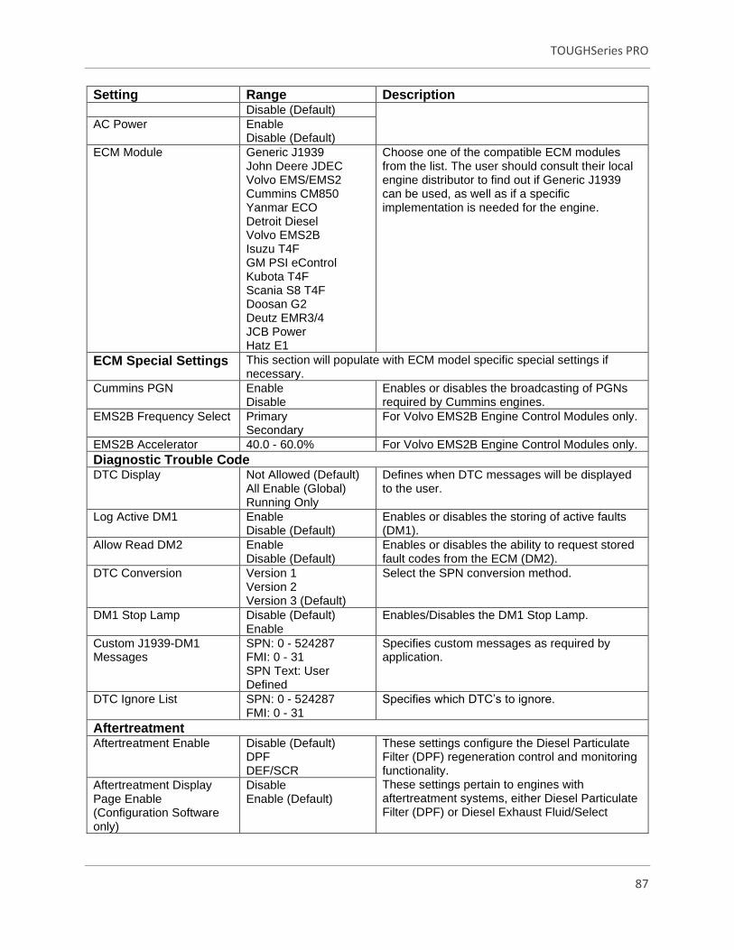
TOUGHSeries PRO
87
Setting Range Description Disable (Default)
AC Power Enable Disable (Default)
ECM Module Generic J1939 John Deere JDEC Volvo EMS/EMS2 Cummins CM850 Yanmar ECO Detroit Diesel Volvo EMS2B Isuzu T4F GM PSI eControl Kubota T4F Scania S8 T4F Doosan G2 Deutz EMR3/4 JCB Power Hatz E1
Choose one of the compatible ECM modules from the list. The user should consult their local engine distributor to find out if Generic J1939 can be used, as well as if a specific implementation is needed for the engine.
ECM Special Settings This section will populate with ECM model specific special settings if necessary.
Cummins PGN Enable Disable
Enables or disables the broadcasting of PGNs required by Cummins engines.
EMS2B Frequency Select Primary Secondary
For Volvo EMS2B Engine Control Modules only.
EMS2B Accelerator 40.0 - 60.0% For Volvo EMS2B Engine Control Modules only.
Diagnostic Trouble Code DTC Display Not Allowed (Default)
All Enable (Global) Running Only
Defines when DTC messages will be displayed to the user.
Log Active DM1 Enable Disable (Default)
Enables or disables the storing of active faults (DM1).
Allow Read DM2 Enable Disable (Default)
Enables or disables the ability to request stored fault codes from the ECM (DM2).
DTC Conversion Version 1 Version 2 Version 3 (Default)
Select the SPN conversion method.
DM1 Stop Lamp Disable (Default) Enable
Enables/Disables the DM1 Stop Lamp.
Custom J1939-DM1 Messages
SPN: 0 - 524287 FMI: 0 - 31 SPN Text: User Defined
Specifies custom messages as required by application.
DTC Ignore List SPN: 0 - 524287 FMI: 0 - 31
Specifies which DTC’s to ignore.
Aftertreatment Aftertreatment Enable Disable (Default)
DPF DEF/SCR
These settings configure the Diesel Particulate Filter (DPF) regeneration control and monitoring functionality. These settings pertain to engines with aftertreatment systems, either Diesel Particulate Filter (DPF) or Diesel Exhaust Fluid/Select
Aftertreatment Display Page Enable (Configuration Software only)
Disable Enable (Default)

TOUGHSeries PRO
88
Setting Range Description Aftertreatment Mode Inhibit
Auto (Default) Last Running
Catalytic Reduction (DEF/SCR), via user configured related settings and display options.
Soot % Display Enable Disable (Default)
Ash % Display Enable Disable (Default)
Time Since Last Regen Display
Enable Disable (Default)
Exhaust Temperature Display
Enable Disable (Default)
DPF Gas Temperature Display
Enable Disable (Default)
DEF/SCR Tank Level Display
Enable Disable (Default)
DEF/SCR Fluid Temperature
Enable Disable (Default)
Password Enable Disable (Default)
Settings Range Description Custom Priority/Address PGN List
Priority: 0-7 PGN: 0 – 65535 Source Address 0 - 255
Select a Custom Priority, PGN, and Source Address through the Rapidcore Software Configurator.
Actual Engine % Torque Enable Disable (Default)
Enables the display of the Actual Engine % Torque parameter from the bus. This is not available for all ECMs.
Percent Engine Load Enable Disable (Default)
Enables the display of the percent Engine Load parameter from the bus. This is not available for all ECMs.
Air Intake Temperature Enable Disable (Default)
Enables the display of the Ambient Air Temperature parameter from the bus. This is not available for all ECMs.
Engine Fuel Rate Enable Disable (Default)
Enables the display of the Engine Fuel Rate parameter from the bus. This is not available for all ECMs.
MOD Bus (RS485)
The MODbus functionality on the controller provides interface ability to PLCs, SCADA and building
management systems.
For detailed information about the MODbus registers and their interpretations please use the MODbus
Reference Manual. The manual can be found at www.dynagen.ca/support.
Setting Range / Values Description
Internal 120Ohm enable Enable Disable (Default)
Allows the use of an internal terminating resistor for RS485 communications lines.

TOUGHSeries PRO
89
Setting Range / Values Description MODbus Enable Enable (Default)
Disable Enable or Disable the use of MODbus communications
Device Address 1 - 247 (Default 1)
The device address of the controller.
Baud Rate (BPS) 9600 (Default) 19200 38400 57400
The speed at which the controller (slave) communicates with the master.
Remote Inputs
The controller has eight Remote Inputs. The operator can write to the controller through MODbus
communication which will trigger designated switched outputs.
Settings Range Descriptions Remote Input 1-8 Label: Remote Input 1 - 8
Output Port: Disable (Default) Port 1 – 10 Active Modes: OFF AUTO Engage Running Cooldown Shutdown Failure
User selectable remote input communication based on switched output and controller state.

TOUGHSeries PRO
90
Miscellaneous
Password
The default password to change settings is "0000". The Password menu is used to create a password for
entering System Settings. (Miscellaneous > Password).
Setting Range Description Bypass Disable (Default)
Enable If enabled a password is not required to change settings.
Timeout 10 - 120 minutes (Default 10 min.)
How long after the password is entered before the user is required to enter it again. The timeout is implemented as a simple countdown timer. The following apply: · If the bypass time is changed this new bypass time will not be loaded until the countdown timer has expired and the user enters the password. · The countdown timer is stored in non-volatile memory and is "paused" when the controller is powered off. The counter will resume when the controller is powered on again. · Any button press in the menu will reset the timer.
Passcode 0000 - 9999 (Default = 0000)
The four numeric digits that make up the password.
Thomson Actuator
The Thomson Actuator can be used for automatic speed control on mechanical engines, with full control
through the TOUGHseries PRO Controller. (Miscellaneous > Thomson Actuator).
Use the following settings configuration to calibrate the Thomson Actuator.
Settings Range Description Actuator Enable Disable (Default)
Enable Enables full control of the Actuator to complete calibration.
Tracking 10 – 50 RPM (Default 30 RPM) The RPM on the Tracking Range allows the engine to proceed over and under the desired RPM. If the load increases or decreases the

TOUGHSeries PRO
91
Settings Range Description RPM past the Tracking Range value, the actuator is calibrated to guide the engine RPM back to the desired RPM in the Tracking Range.
Calibration Active * Disable (Default) 1000 - 3000
The Calibration Active number is programmed specifically for the Actuator. This will enable the Actuator Calibration, allowing the controller to posses full control over the Thomson Actuator. The Calibration number is 2039.
Manual Adjust* 0% - 100% (Default 100%) Setting a value to the Manual Adjust will precisely guide the actuator to the desired location before start up. 100% is the maximum distance that the actuator can extend. Decreasing the percent downward by the value of one will cause the Actuator to decline in exact decrements.
Idle Position* 5% or 95% (Default 95%) The Idle position percentage is the miniature amount of the Actuator stroke that is locked and can not proceed below or above the specific percentage. If the Actuator is pushing then the Idle Position should be set to 5%. The Actuator stroke will not go below 5%. If the Actuator is pulling then the Idle Position should be set to 95%. The Actuator Stroke will not go above 95%.
*Calibration Active, Manual Adjust, and Idle Position are only accessible through the settings in the
controller. These three settings are not accessible through the Rapidcore Configuration Software.
*Adjust the throttle cable so when the Actuator stroke is set to 5% or 95% it approximately gives the user
the Idle speed.
Follow the steps below to complete the Actuator Calibration Run:
• Exit menu settings > Enter Auto mode > Press the Run button to begin the Calibration Run.
*A message will appear on the controller screen saying “Actuator Calibration… Wait for Position Adjust”
• Press the “Pager” button directly to the right of the Auto button, refer to Figure 11: Controller
Button Description.

TOUGHSeries PRO
92
*Once that is complete “Calibration All Done!” message will appear on the screen of the controller.
• Press the Off button to return to Off mode.
Fuel Select
The Fuel Select is an operator facing option which allows the user to configure two fuel types.
Setting Range Description Fuel Type Enable: Fuel 1 (Default)
Fuel 2 When Fuel 2 is selected it will activate the assigned switched output. When Fuel 1 is selected it does not activate the switched output, this gives the user the ability to acknowledge which fuel type is selected.
Fuel Indication Disable (Default) Enable
This allows the user to enable or disable the fuel type indication message. When enabled the indication message will appear on the screen of the controller.
Remote Set Fuel Disable (Default) Enable
Not available.
Fuel 1 Text
Custom Text (Default) The user can select the desired name for fuel type 1.
Fuel 2 Text Custom Text (Default) The user can select the desired name for fuel type 2.
Refer to Switched Outputs > Programmable Output for more information on programming the Fuel Type
Switched Output.

TOUGHSeries PRO
93
Troubleshooting
If you are having issues with your controller, please refer to the table below for a solution before
contacting technical support.
NOTE: Always check the DynaGen website for the latest software, firmware and user
manuals
Issue Solution Engine starts but the crank output does not turn off
Controller is not receiving a speed signal. 1. Verify the Sensors > Engine Speed > Signal Source setting is set correctly. 2. Verify the Timers > Engine Logic > RPM Disconnect setting is set correctly. 3. Ensure the correct wiring to the controller. For magnetic pickup, Speed Sensing A and B terminals are used. For generator voltage, the AC voltage connections are used.
Sensor always displays its lowest or highest value
The sensor could either be open (not connected) or shorted to ground. Verify your connections and ensure the correct sender table is loaded.
High Engine Temperature Trip
Issue: Engine Temperature is inaccurate or shifting frequently on non isolated (signal terminal) senders. Solution: Check that the ground from the negative of the battery to the sensor is in fine condition. If needed, run a wire (or use sensor ground on the controller) to the sensor body. Do not rely on the engine chassis. Solution: Consider twisted pair wiring to reduce/eliminate the affects of electrical noise.
Can not communicate via CAN bus
Doublecheck addressing using the PGN list in the J1939 reference manual. The manual can be found at www.dynagen.ca/support.
Can not communicate via Modbus
Doublecheck the Modbus command being used to communicate with the controller and the registers that are being read and written using the Modbus reference manual. Also ensure that the bus is terminated with 120Ω resistors. The manual can be found at www.dynagen.ca/support.

TOUGHSeries PRO
94
Contact Information
Contacting DynaGen can be done by any of the methods below. Technical support is offered Monday to Friday, 8:00am - 4:00pm (EST).
Method Information Website www.dynagen.ca/support
Email [email protected]
Phone Number (902) 406-0133
Twitter @DynaGenTech
Address 3 Spectacle Lake Drive, Unit B105 Dartmouth, NS B3B1W8, Canada