Embed Size (px)
Citation preview
TE-10A, TE-10D and TU-20D
ThermoregulatorOperator’s Manual
InsTrUcTIOns fOr UsE
Issue 1510/11
TE-10A, TE-10D AnD TU-20D OpErATOr’s MAnUAl
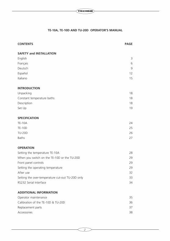
cOnTEnTs pAgE
sAfETY and InsTAllATIOn
English 3
Français 6
Deutsch 9
Español 12
Italiano 15
InTrODUcTIOn
Unpacking 18
Constant temperature baths 18
Description 18
Set Up 19
spEcIfIcATIOn
TE-10A 24
TE-10D 25
TU-20D 26
Baths 27
OpErATIOn
Setting the temperature TE-10A 28
When you switch on the TE-10D or the TU-20D 29
Front panel controls 29
Setting the operating temperature 29
After use 32
Setting the over-temperature cut-out TU-20D only 33
RS232 Serial Interface 34
ADDITIOnAl InfOrMATIOn
Operator maintenance 35
Calibration of the TE-10D & TU-20D 36
Replacement parts 37
Accessories 38
2
sAfETY AnD InsTAllATIOn
Please read all the information in this booklet before using the unit.
WArnIng
HIGH TEMPERATURES ARE DANGEROUS: they can cause serious burns to operators and ignite combustible material.
Techne have taken great care in the design of these units to protect operators from hazards, but operators should pay attention to the following points:
• USE CARE AND WEAR PROTECTIVE GLOVES TO PROTECT HANDS;• DO NOT put hot objects on or near combustible objects;• DO NOT operate the unit close to inflammable liquids or gases;• At all times USE COMMON SENSE.
OpErATOr sAfETY
All operators of Techne equipment must have available the relevant literature needed to ensure their safety. It is important that only suitably trained personnel operate this equipment, in accordance with the instructions contained in this manual and with general safety standards and procedures. If the equipment is used in a manner not specified by Techne the protection provided by the equipment to the operator may be impaired.
All Techne units have been designed to conform to international safety requirements and are fitted with an over-temperature cut-out. On some models, the cut-out is adjustable and should be set to suit the application. On all other models the cut-out is preset to protect the unit.
If a safety problem should be encountered, switch off at the mains socket and remove the plug from the supply.
InsTAllATIOn
1. All Techne units are supplied with a power cable. This may be integral or plug-in.
2. Before connecting the mains supply, check the voltage against the rating plate. The rating plate is on the rear of the unit. Connect the mains cable to a suitable plug according to the table below.
note that the unit must be earthed to ensure proper electrical safety.
Connections 220V-240V 110V-120VLive Brown BlackNeutral Blue WhiteEarth Green/yellow Green
The fused plug supplied with the mains lead for use in the UK is fitted with the following value fuse to protect the cable: 5 AMP for TE-10A and TE-10D; 10AMP for the TU-20D.
3
The fuse in the unit protects the unit and the operator
Note that units marked 230V on the rating plate work at 220V; units marked 120V work at 110V. In both cases, however, the heating rate will degrade by approximately 8%.
3. Plug the mains cable into the socket on the rear of the unit.
4. Do not switch on until the unit is fully installed, see page 19.
5. Note that the following symbols may be next to the indicator lamps on the front panel of the units and have the following meanings:
the power indicator
the heater indicator
the over-temperature indicator
6. Symbols on or near the power switch of the unit have the following meanings:
I mains switch On
O mains switch Off
WOrkIng EnvIrOnMEnT (all units)
The Thermoregulator units are designed to work safely under the following conditions:
Ambient temperature range 5°C to 40°C
Humidity - up to 95% relative humidity, non-condensing
note: The control specifications quoted are for an ambient temperature range of 10°C to 30°C. The specification may deteriorate outside this range but the unit will still work safely.
Radio frequency interference tested and passed to EN50081-1.
Immunity Tested and passed to EN50082-1
gUArAnTEE
The unit is guaranteed against any defect in material or workmanship for the period specified on the enclosed guarantee card. This period is from the date of purchase, and within this period all defective parts will be replaced free of charge provided that the defect is not the result of misuse, accident or negligence. Servicing under this guarantee should be obtained from the supplier.
Notwithstanding the description and specification(s) of the units contained in the operator’s manual, Techne hereby reserves the right to make such changes as it sees fit to the units or to any component of the units.
This manual has been prepared solely for the convenience of Techne customers and nothing in this instruction book shall be taken as a warranty, condition or representation concerning the description, merchantability, fitness for purpose or otherwise of the units or components.
4
OpErATOr MAInTEnAncE
NOTE: THAT THIS EQUIPMENT SHOULD ONLY BE DISMANTLED BY PROPERLY TRAINED PERSONNEL.REMOVING THE SIDE, FRONT OR REAR PANELS EXPOSES POTENTIALLY LETHAL MAINS VOLTAGES.THERE ARE NO OPERATOR MAINTAINABLE PARTS WITHIN THE EQUIPMENT.
In the unlikely event that you experience any problems with your unit which cannot easily be remedied, you should contact your supplier and return the unit if necessary. Please include any details of the fault observed and remember to return the unit in its original packing. Techne accept no responsibility for damage to units which are not properly packed for shipping: if in doubt, contact your supplier. See the Decontamination Certificate supplied with your unit.
1. cleaning
Before cleaning your unit ALWAYS disconnect it from the power supply and allow it to cool below 50°C.
Your unit can be cleaned by wiping with a damp soapy cloth. Care should be exercised to prevent water from running inside the unit. Do not use abrasive cleaners.
2. Over-temperature cut-out
In the event of no heater power, check the mains plug and lead. Repeated operation of the cut-out indicates a serious fault: you may need to return the unit to your supplier for repair.
3. fuses
Your unit is protected by one or two fuses. These should only be changed by suitably qualified personnel. If the fuses blow persistently, a serious fault is indicated and you may need to return the unit to your supplier for repair.
cOnTAcT InfOrMATIOn
For technical, sales or servicing information, contact your local Techne dealer or
Uk and rest of WorldBibby Scientific LtdBeacon Road, Stone,Staffordshire, ST15 0SA, UKTel: +44 (0)1785 812121 Fax: +44 (0)1785 813748e-mail: [email protected]
north and south AmericaTechne Inc.3 Terri Lane, Suite 10,Burlington, NJ, 08016, USAToll free: 800-225-9243Tel: +1 609-589-3560Fax: +1 609-589-2571e-mail: [email protected]
5
InTrODUcTIOn
Veuillez lire attentivement toutes les instructions de ce document avant d’utiliser l’appareil.
AvErTIssEMEnT
DANGER DE TEMPERATURES ELEVEES : les opérateurs peuvent subir de graves brûlures et les matériaux combustibles risquent de prendre feu.
Techne a apporté un soin tout particulier à la conception de ces appareils de façon à assurer une protection maximale des opérateurs, mais il est recommandé aux utilisateurs de porter une attention spéciale aux points suivants :
• PROCEDER AVEC SOIN ET PORTER DES GANTS POUR SE PROTEGER LES MAINS.• NE PAS poser d’objets chauds sur ou près de matériaux combustibles.• NE PAS utiliser l’appareil à proximité de liquides ou de gaz inflammables. • NE PAS verser de liquide directement dans l’appareil. • FAIRE TOUJOURS PREUVE DE BON SENS.
sécUrITé DE l’OpérATEUr
Tous les utilisateurs de produits Techne doivent avoir pris connaissance des manuels et instructions nécessaires à la garantie de leur sécurité.
Important : cet appareil doit impérativement être manipulé par un personnel qualifié et utilisé selon les instructions données dans ce document, en accord avec les normes et procédures de sécurité générales. Dans le cas où cet appareil ne serait pas utilisé selon les consignes précisées par Techne, la protection pour l’utilisateur ne serait alors plus garantie.
Tous les appareils Techne sont conçus pour répondre aux normes de sécurité internationales et sont dotés d’un coupe-circuit en cas d’excès de température. Sur certains modèles, ce coupe-circuit est réglable pour s’adapter à l’application désirée. Sur d’autres modèles, il est pré-réglé en usine pour assurer la protection de l’appareil.
Dans le cas d’un problème de sécurité, coupez l’alimentation électrique au niveau de la prise murale et enlevez la prise connectée à l’appareil.
InsTAllATIOn
1. Tous les appareils Techne sont livrés avec un câble d’alimentation qui peut être intégré à l’appareil ou à raccorder.
2. Avant de brancher l’appareil, vérifiez la tension requise indiquée sur la plaque d’identification. Raccordez le câble électrique à la prise appropriée en vous reportant au tableau ci-dessous. Il est important que l’appareil soit relié à la terre pour assurer la protection électrique requise.
Connexions 220V-240 V 110V-120 V Phase marron noir Neutre bleu blanc Terre vert/jaune vert
Le fusible à l’intérieur de l’appareil est destiné à assurer la protection de l’appareil et de l’opérateur.
6

Remarque : les appareils dont la plaque indique 230 V peuvent fonctionner sur 220 V, et ceux dont la plaque indique 120 V peuvent fonctionner sur 110 V. Dans les deux cas cependant, la capacité de chauffage diminuera d’environ 8 %. La plaque d’identification se trouve à l’arrière de l’appareil.
3. Raccordez le câble d’alimentation à la prise située à l’arrière de l’appareil.
4. Placez l’appareil sur un plan de travail ou surface plane, ou le cas échéant, dans une hotte d’aspiration, en s’assurant que les trous d’aération situés sous l’appareil ne soient pas obstrués.
5. Les symboles ci-dessous situés à côté des témoins lumineux sur la face avant de l’appareil ont la signification suivante :
: témoin d’alimentation : témoin de chauffage : témoin d’excès de température
6. Les symboles situés sur ou à côté de l’interrupteur de l’appareil ont la signification suivante :
O : arrêt l : marche
Après UTIlIsATIOn
Lorsque vous avez fini de chauffer les échantillons, n’oubliez pas que certaines parties de l’appareil - les éprouvettes, leurs supports et autres accessoires - risquent d’être très chaudes. Il est donc recommandé de toujours prendre les précautions citées plus haut.
gArAnTIE
L’appareil est garanti contre tout défaut ou visde fabrication pour la durée figurant sur la carte de garantie, à compter de la date d’achat de l’appareil. Au cours de cette période, toutes les pièces défectueuses seront remplacées gratuitement, dans la mesure où la défaillance n’est pas due à une mauvaise utilisation, un accident ou une négligence. Toute réparation sous garantie sera effectuée par le fournisseur.
Malgré la description et les spécifications de l’appareil données dans le manuel de l’utilisateur, Techne se réserve le droit d’effectuer les changements nécessaires à l’appareil ou à tout élément qui entre dans sa composition.
Ce manuel a été exclusivement rédigé à l’attention des clients de Techne, et aucun élément de ce guide d’instructions ne peut être utilisé comme garantie, condition ou représentation concernant la description, commercialisation, adaptation aux conditions d’utilisation ou autre des appareils ou leurs composants.
7
EnTrETIEn UTIlIsATEUr
IMPORTANT : CET APPAREIL NE PEUT ETRE DEMONTE QUE PAR DU PERSONNEL QUALIFIE.
LORSQUE LES PANNEAUX AVANT, ARRIERE ET LATERAUX SONT DEMONTES, L’OPERATEUR EST EXPOSE A DES TENSIONS QUI PEUVENT ETRE MORTELLES.
CET APPAREIL NE CONTIENT AUCUN ELEMENT QUI DEMANDE UN ENTRETIEN DE LA PART DE L’UTILISATEUR.
Dans le cas peu probable où votre appareil présente un défaut de fonctionnement auquel il est difficile de remédier, il est alors préférable de contacter votre fournisseur et, le cas échéant, de renvoyer le matériel. Veuillez inclure une description détaillée du problème constaté et retourner l’appareil dans son emballage d’origine. Techne ne sera pas tenu responsable des dommages subis par tout appareil dont l’emballage est inadéquat pour le transport. Pour plus de sûreté, contactez votre fournisseur. Voir le certificat de décontamination livré avec le produit.
1. nettoyage
Avant de nettoyer l’appareil, assurez-vous TOUJOURS que le câble d’alimentation est déconnecté et laissez la température redescendre en dessous de 50°C.
Utilisez un chiffon imprégné d’eau savonneuse pour nettoyer l’appareil. Veillez à ne pas introduire d’eau dans l’appareil. N’utilisez pas de produits abrasifs.
2. coupe-circuit d’excès de température
• En l’absence de puissance de chauffe, vérifiez la prise et le câble d’alimentation puis réglez la commande du coupe-circuit (si votre appareil est doté de ce mécanisme).
• Si la sécurité se déclenche trop souvent, il s’agit d’un problème plus sérieux. Nous vous conseillons dans ce cas de prendre contact avec votre fournisseur pour réparation.
3. fusibles
La protection de l’appareil est assurée par un ou deux fusibles dont le remplacement ne peut être effectué que par un personnel qualifié.
Si les fusibles sautent sans arrêt, il s’agit d’un problème sérieux. Nous vous conseillons dans ce cas de prendre contact avec votre fournisseur pour réparation.
8
EInlEITUng
Bitte lesen Sie diese Bedienungsanleitung komplett bevor Sie dieses Gerät benutzen.
WArnUng
HOHE TEMPERATUREN SIND GEFÄHRLICH: sie können dem Bediener ernsthafte Verletzungen zufügen und brennbare Materialien können sich leicht entzünden.
Techne hat bei der Konstruktion dieses Gerätes sehr darauf geachtet, daß der Bediener vor Gefahren geschützt ist. Dennoch sollten Sie auf die folgenden Punkte achten:
• SEIEN SIE VORSICHTIG UND TRAGEN SIE SCHUTZHANDSCHUHE• Legen Sie heiße Gegenstände NICHT auf oder in die Nähe von leicht brennbaren Materialien;
vermeiden Sie Arbeiten in der Nähe von leicht entzündbaren Flüssigkeiten oder Gasen.• Bringen sie KEINE Flüssigkeiten direkt in Ihr Gerät.• Benutzen Sie immer den normalen Menschenverstand
sIchErhEIT DEs AnWEnDErs
Alle Benutzer von Techne Geräten müssen Zugang zu der entsprechenden Literatur haben, um ihre Sicherheit zu gewähren.
Es ist wichtig, daß diese Geräte nur von entsprechend geschultem Personal betrieben werden, das die in dieser Gebrauchsanweisung enthaltenen Maßnahmen und allgemeine Sicherheitsbestimmungen und -vorkehrungen beachtet. Wenn das Gerät anders eingesetzt wird als vom Hersteller empfohlen, kann dies die persönliche Sicherheit des Anwenders beeinträchtigen. Die Geräte von Techne entsprechen den internationalen Sicherheitsbestimmungen und sind mit einem automatischen Übertemperaturabschalter ausgestattet. Bei einigen Modellen ist der Übertemperaturabschalter verstellbar und sollte je nach Anwendung entsprechend eingestellt werden. Bei allen anderen Modellen ist der Temperaturschutz voreingestellt um Schäden am Gerät zu vermeiden. Wenn ein Sicherheitsproblem auftreten sollte, muß das Gerät ausgeschaltet und vom Stromnetz getrennt werden.
InsTAllATIOn
1. Alle Techne Geräte werden mit einem Stromanschlußkabel geliefert. Dieses ist entweder fest mit dem Gerät verbunden oder zum Einstecken.
2. Vergleichen Sie, ob die Spannung Ihrer Stromversorgung mit den Angaben auf dem Typenschild des Geräte übereinstimmen. Verbinden Sie das Stromanschlußkabel mit einer geeigneten Stromversorgung gemäß der nächstehenden Tabelle.
Achtung: Das gerät muß geerdet sein, um die elektrische sicherheit zu gewährleisten!
Verbindungen 220V-240V 110V-120V Stromführend Braun Schwarz Neutral Blau Weiß Erde Grün/Gelb Grün
Geräte, die für 230 Volt ausgelegt sind, können auch bei 220 Volt arbeiten, Geräte für 120 Volt auch bei 110 Volt. In beiden Fällen verringert sich die Aufheizrate um ca. 8%. Das Typenschild befindet sich hinten am Gerät.
9
3. Stecken Sie das Stromkabel in die vorgesehene Buchse hinten am Gerät.
4. Stellen Sie das Gerät auf eine ebene Arbeitsfläche bzw. (falls erforderlich) unter einen Laborabzug. Beachten Sie, daß die Entlüftungsrippen an der Geräteunterseite immer frei zugänglich sind.
5. Wenn die Anzeigenlämpchen an der Vorderseite leuchten, hat dies folgende Bedeutung:
: Gerät ist eingeschaltet
: Gerät heizt
: Übertemperaturschutz ist ausgelöst
6. Die Symbole auf oder neben dem EIN/AUS-Schalter an der Geräterückseite bedeuten:
I : An
O : Aus
nAch DEM gEbrAUch
Vergessen Sie nicht, daß Teile des Gerätes (die Gefäße, die Blöcke und andere Zubehörteile) nach dem Erhitzen von Proben noch sehr heiß sein können. Bitte beachten Sie die oben genannten Vorsichtsmaßnahmen.
gArAnTIE
Die Garantiedauer des Gerätes ist auf der beiliegenden Garantiekarte angegeben und schließt Fehler im Material oder der Verarbeitung ein. Die Garantiedauer beginnt am Tag des Einkaufs. Sämtliche defekte Teile werden innerhalb dieses Zeitraumes kostenlos ersetzt unter der Voraussetzung, daß dem Defekt keine unsachgemäße Handhabung, Fahrlässigkeit oder ein Unfall zugrundeliegt. Der unter diese Garantie fallende Service wird vom Lieferanten geleistet.
Ungeachtet der in dieser Gebrauchsanweisung enthaltenen Beschreibungen und Spezifikationen, behält sich Techne hiermit das Recht vor, Änderungen an den Geräten bzw. an einzelnen Geräteteilen durchzuführen.
Diese Gebrauchsanleitung wurde ausschließlich dazu erstellt, um Kunden die Handhabung der Techne-Geräte zu erleichtern. Nichts in dieser Gebrauchsanleitung darf als Garantie, Bedingung oder Voraussetzung verstanden werden, sei es die Beschreibung, Marktgängigkeit, Zweckdienlichkeit oder sonstiges bezüglich der Geräte oder deren Bestandteile.
WArTUng DUrch DEn bEDIEnEr
BEACHTEN SIE, DASS DIESES GERÄT NUR VON TECHNISCHEN FACHKRÄFTEN GEÖFFNET UND DEMONTIERT WERDEN DARF.
DURCH ENTFERNEN DES GERÄUSES ODER GEHÄUSETEILEN SIND BAUTEILE MIT LEBENGEFÄHRLICHEN SPANNUNGEN FREI ZUGÄNGLICH.
IM INNERN DES GERÄTES BEFINDEN SICH KEINE TEILE, DIE VOM ANWENDER GEWARTET WERDEN MÜSSEN.
Falls Ihr Gerät nicht ordnungsgemäß arbeitet, wenden Sie sich an Ihren Lieferanten oder senden Sie das
10
Gerät wenn nötig zurück. Fügen Sie eine genaue Beschreibung des Defektes bei. Verpacken Sie das Gerät möglichst im Originalkarton. Bitte beachten Sie, daß Techne und thermo-DUX keine Haftung bei Transportschäden aufgrund unzureichender Verpackung übernehmen. Setzen Sie sich im Zweifelsfall mit Ihrem Lieferanten in Verbindung. Bitte beachten Sie die Entgiftungsbescheinigung, die Sie mit dem Gerät erhalten haben.
1. reinigen
Bevor Sie Ihr Gerät reinigen, sollten Sie
• zuerst den Netzstecker ziehen
• das Gerät unter 50°C abkühlen lassen.
Ein feuchtes Tuch mit Seifenlösung reinigt Ihr Gerät am besten. Achten Sie darauf, daß kein Wasser in das Gerät gelangt. Verwenden Sie keine Scheuermittel.
2. Übertemperaturabschalter
• Der Übertemperaturschutz ist ein empfindliches mechanisches Teil. Schon eine Erschütterung kann diesen auslösen.
• Falls die Heizung nicht funktioniert, überprüfen Sie zuerst Netzstecker und Kabel. Setzen Sie dann den Übertemperaturabschalter (an der Rückseite des Gerätes) wieder zurück, indem Sie den roten Knopf einmal bis zum Anschlag drücken.
• Wenn der Übertemperaturabschalter wiederholt auslöst, liegt ein größerer Defekt vor. Das Gerät muß zur Reparatur an Ihren Lieferanten eingesandt werden.
3. sicherungen
Die Stromzuleitung ist durch ein oder zwei Sicherungen geschützt. Diese sollten nur durch qualifiziertes Fachpersonal ausgetauscht werden. Wenn die Sicherung wiederholt durchbrennt, liegt ein größerer Defekt vor. Das Gerät muß zur Reparatur an Ihren Lieferanten eingesandt werden.
11
InTrODUccIón
Le rogamos lea cuidadosamente la información contenida en este folleto antes de manipular el aparato.
AvIsO
LAS TEMPERATURAS ELEVADAS SON PELIGROSAS: pueden causarle graves quemaduras y provocar fuego en materiales combustibles.
Techne ha puesto gran cuidado en el diseño de estos aparatos para proteger al usuario de cualquier peligro; aún así se deberá prestar atención a los siguientes puntos:
• EXTREME LAS PRECAUCIONES Y UTILICE GUANTES PARA PROTEGERSE LAS MANOS;• NO coloque objetos calientes encima o cerca de objetos combustibles;• NO maneje el aparato cerca de líquidos inflamables o gases;• NO introduzca ningún líquido directamente en el aparato;• UTILICE EL SENTIDO COMUN en todo momento.
sEgUrIDAD DEl UsUArIO
Todos los usuarios de equipos Techne deben disponer de la información necesaria para asegurar su seguridad.
De acuerdo con las instrucciones contenidas en este manual y con las normas y procedimientos generales de seguridad, es muy importante que sólo personal debidamente capacitado opere estos aparatos. De no ser así, la protección que el equipo le proporciona al usuario puede verse reducida.
Todos los equipos Techne han sido diseñados para cumplir con los requisitos internacionales de seguridad y traen incorporados un sistema de desconexión en caso de sobretemperatura. En algunos modelos el sistema de desconexión es variable, lo que le permite elegir la temperatura según sus necesidades. En otros, el sistema de desconexión viene ya ajustado para evitar daños en el equipo.
En caso de que surgiera un problema de seguridad, desconecte el equipo de la red.
InsTAlAcIón
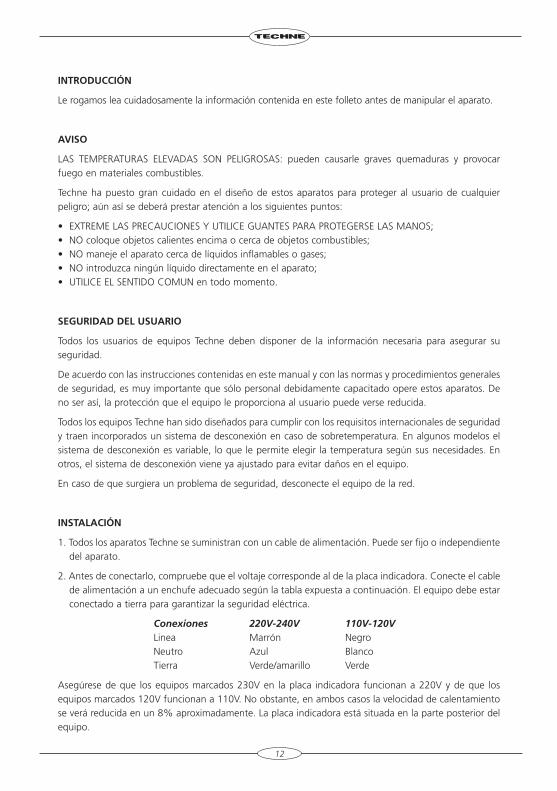
1. Todos los aparatos Techne se suministran con un cable de alimentación. Puede ser fijo o independiente del aparato.
2. Antes de conectarlo, compruebe que el voltaje corresponde al de la placa indicadora. Conecte el cable de alimentación a un enchufe adecuado según la tabla expuesta a continuación. El equipo debe estar conectado a tierra para garantizar la seguridad eléctrica.
Conexiones 220V-240V 110V-120V Linea Marrón Negro Neutro Azul Blanco Tierra Verde/amarillo Verde
Asegúrese de que los equipos marcados 230V en la placa indicadora funcionan a 220V y de que los equipos marcados 120V funcionan a 110V. No obstante, en ambos casos la velocidad de calentamiento se verá reducida en un 8% aproximadamente. La placa indicadora está situada en la parte posterior del equipo.
12
3. Conecte el cable a la toma de tensión en la parte posterior del equipo.
4. Sitúe el aparato en un lugar apropiado tal como una superficie de trabajo plana, o si fuera necesario incluso en una campana con extractor de humos, asegurándose de que las entradas de aire en la parte inferior no queden obstruidas.
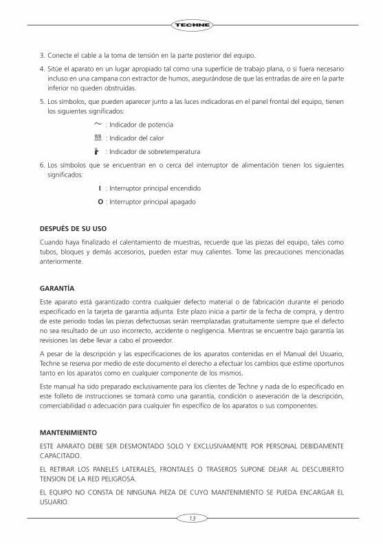
5. Los símbolos, que pueden aparecer junto a las luces indicadoras en el panel frontal del equipo, tienen los siguientes significados:
: Indicador de potencia
: Indicador del calor
: Indicador de sobretemperatura
6. Los símbolos que se encuentran en o cerca del interruptor de alimentación tienen los siguientes significados:
I : Interruptor principal encendido
O : Interruptor principal apagado
DEspUés DE sU UsO
Cuando haya finalizado el calentamiento de muestras, recuerde que las piezas del equipo, tales como tubos, bloques y demás accesorios, pueden estar muy calientes. Tome las precauciones mencionadas anteriormente.
gArAnTíA
Este aparato está garantizado contra cualquier defecto material o de fabricación durante el periodo especificado en la tarjeta de garantía adjunta. Este plazo inicia a partir de la fecha de compra, y dentro de este periodo todas las piezas defectuosas serán reemplazadas gratuitamente siempre que el defecto no sea resultado de un uso incorrecto, accidente o negligencia. Mientras se encuentre bajo garantía las revisiones las debe llevar a cabo el proveedor.
A pesar de la descripción y las especificaciones de los aparatos contenidas en el Manual del Usuario, Techne se reserva por medio de este documento el derecho a efectuar los cambios que estime oportunos tanto en los aparatos como en cualquier componente de los mismos.
Este manual ha sido preparado exclusivamente para los clientes de Techne y nada de lo especificado en este folleto de instrucciones se tomará como una garantía, condición o aseveración de la descripción, comerciabilidad o adecuación para cualquier fin específico de los aparatos o sus componentes.
MAnTEnIMIEnTO
ESTE APARATO DEBE SER DESMONTADO SOLO Y EXCLUSIVAMENTE POR PERSONAL DEBIDAMENTE CAPACITADO.
EL RETIRAR LOS PANELES LATERALES, FRONTALES O TRASEROS SUPONE DEJAR AL DESCUBIERTO TENSION DE LA RED PELIGROSA.
EL EQUIPO NO CONSTA DE NINGUNA PIEZA DE CUYO MANTENIMIENTO SE PUEDA ENCARGAR EL USUARIO.
13
En el caso improbable de que experimentara algún problema con su aparato que no pudiera resolver con facilidad, debería ponerse en contacto con su proveedor y devolverlo si fuera necesario. Indique de forma detallada todos los defectos que haya notado y devuelva el equipo en su embalaje original. Techne no aceptará responsabilidad alguna por daños causados en equipos que no estuvieran debidamente embalados para su envío; si tuviera alguna duda, póngase en contacto con su proveedor. Sírvase consultar el Certificado de Descontaminación suministrado con su aparato.
1. limpieza
Antes de limpiar su aparato, desconéctelo SIEMPRE de la fuente de alimentación y permita que se enfríe por debajo de los 50°C.
Este aparato se puede limpiar pasándole un paño húmedo enjabonado. Hágalo con cuidado parae evitar que caiga agua dentro del mismo. No utilice limpiadores abrasivos.
2. Desconexión en caso de sobretemperaturas
El sistema de desconexión en caso de sobretemperaturas es un dispositivo mecánico sensible (una sacudida mecánica podría desconectarlo).
• Si el calefactor no recibiera alimentación, compruebe el enchufe y el cable de la toma de corriente; a continuación vuelva a ajustar el control del dispositivo (si su equipo lo lleva montado).
• Una desconexión repetida indicaría una avería grave; puede que tenga que devolverle el aparato a su proveedor para su reparación.
3. fusibles
Su aparato está protegido por uno o dos fusibles. Sólo deben cambiarlos personal debidamente capacitado.
Si los fusibles se fundieran repetidamente, esto indicaría una avería grave y puede que tuviera que devolverle el aparato a su proveedor para su reparación.
14
InTrODUzIOnE
Prima di utilizzare l’apparecchio, leggere tutte le informazioni contenute in questo manuale.
ATTEnzIOnE
Le alte temperature sono pericolose: possono causare ustioni gravi all’utilizzatore e possono causare la combustione di materiale infiammabile. La Techne ha posto particolare cura nel progettare questo strumento, al fine di proteggere gli operatori da eventuali pericoli, ma gli utilizzatori devono prestare attenzione ai seguenti punti:
• Utilizzare con attenzione e indossare guanti protettivi; • Non mettere vicini oggetti caldi o oggetti infiammabili; • Non azionare il riscaldatore Techne vicino a liquidi infiammabili o benzine; • Non introdurre nessun liquido all’interno dell’ unità; • In ogni caso Usare Buon Senso.
sIcUrEzzA pEr l’UTIlIzzATOrE
Il personale che utilizza l’apparecchiatura Techne deve avere a disposizione la documentazione necessaria al fine di assicurare la loro incolumità.
È importante che solo personale adeguatamente addestrato utilizzi questo apparecchio, in conformità alle istruzioni contenute in questo manuale e nel rispetto delle normative e procedure generali di sicurezza. Se l’apparecchio è utilizzato in modo non specificato da Techne, la protezione fornita dall’apparecchiatura all’utilizzatore potrebbe essere a rischio.
Tutte le unità Techne sono state progettate in conformità ai requisiti internazionali di sicurezza e sono equipaggiate con un interruttore anti surriscaldamento. Su alcuni modelli, l’interruttore è regolabile e dovrebbe essere impostato secondo l’utilizzo. In tutti gli altri modelli l’interruttore è preregolato per proteggere l’unità.
Se si dovesse verificare qualche problema di sicurezza, disconnettere l’apparecchio dalla rete.
InsTAllAzIOnE
1. Tutti gli apparecchi Techne sono forniti di un cavo di alimentazione. Questo può essere integrato nell’apparecchio o separato.
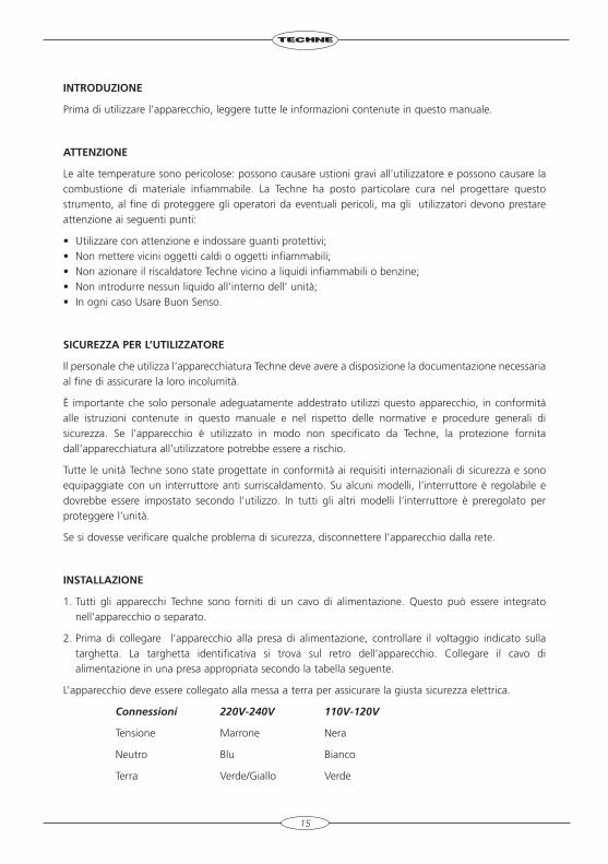
2. Prima di collegare l’apparecchio alla presa di alimentazione, controllare il voltaggio indicato sulla targhetta. La targhetta identificativa si trova sul retro dell’apparecchio. Collegare il cavo di alimentazione in una presa appropriata secondo la tabella seguente.
L’apparecchio deve essere collegato alla messa a terra per assicurare la giusta sicurezza elettrica.
Connessioni 220V-240V 110V-120V
Tensione Marrone Nera
Neutro Blu Bianco
Terra Verde/Giallo Verde
15
Il fusibile all’interno dell’apparecchio protegge l’apparecchiatura e l’utilizzatore.
Tenere presente che gli apparecchi riportanti sulla targhetta 230 V funzionano a 220V. Gli apparecchi riportanti 120V funzionano a 110V. Comunque, in entrambi i casi la velocità di riscaldamento diminuirà approssimativamente dell’8%.
3. Collegare il cavo elettrico alla presa di corrente sul retro dell’unità.
4. Posizionare l’unità su un luogo adeguato, su una superficie di lavoro piana oppure, se necessario, sotto una cappa aspiratrice, assicurandosi che le prese di aria sulla parte inferiore siano libere da ostruzione.
5. I simboli seguenti, che possono essere collocati in prossimità delle luci di indicazione sul pannello anteriore dell’apparecchio, hanno i seguenti significati:
indicatore di potenza
indicatore di riscaldamento
indicatore di surriscaldamento
6. I simboli sopra o vicino l’interruttore di accensione dell’apparecchio hanno i significati seguenti:
I Acceso
O Spento
DOpO l’UsO
Quando avrete terminato di riscaldare i campioni, ricordate che le parti dell’apparecchio – le provette, i loro supporti e gli altri accessori – possono essere bollenti. Seguire le precauzioni elencate in precedenza.
gArAnzIA
L’apparecchio è garantito contro ogni difetto del materiale o fabbricazione per il periodo specificato sul certificato di garanzia accluso. Questo periodo decorre dalla data di acquisto, e durante il quale tutte le parti difettose verranno sostituite gratuitamente purché il difetto non sia causato da un uso non appropriato, da cause non imputabili a difetti di fabbricazione o negligenza. L’assistenza durante questo periodo sarà garantita dal fornitore.
Ferme restando la descrizione e le caratteristiche dell’apparecchio contenute nel Manuale d’uso dell’utilizzatore, la Techne si riserva in ogni caso il diritto di effettuare le modifiche che riterrà necessarie all’apparecchio o ai suoi componenti.
Questo Manuale è stato realizzato esclusivamente a vantaggio dei clienti della Techne e in alcun modo potrà essere utilizzato come garanzia, condizione o rappresentazione concernente la descrizione, commercializzazione, adeguamento alle condizioni di utilizzo o altro degli apparecchi o delle sue componenti.
MAnUTEnzIOnE
Questo apparecchio dovrà essere aperto esclusivamente da Personale adeguatamente addestrato. La rimozione dei pannelli laterali, frontali o posteriori può esporre potenzialmente a voltaggi di corrente letali. All’interno dell’apparecchio non ci sono parti manutenibili da parte dell’utilizzatore.
16
Nell’eventualità che si riscontri un problema con l’apparecchio che non può essere facilmente risolto, si dovrà contattare il proprio fornitore e restituire, se necessario, l’apparecchio. Si prega di specificare nel dettaglio i difetti riscontrati e di ricordare di restituire l’apparecchio nel suo involucro originale. La Techne non si fa carico di alcuna responsabilità per danni subiti dall’apparecchio che non sia stato propriamente imballato per il trasporto; in caso di dubbio, rivolgersi al fornitore. Vedere il Certificato di Decontaminazione fornito con il vostro apparecchio.
1. pulizia
Prima di pulire il vostro apparecchio, disconnettere sempre la presa di alimentazione e lasciare raffreddare sotto i 50°C. Questo apparecchio può essere pulito passando un panno inumidito con sapone. Si deve prestare attenzione onde prevenire l’ingresso dell’acqua all’interno dell’apparecchio. Non utilizzare per la pulizia sostanze abrasive.
2. Disconnessione in caso di surriscaldamento
In caso di non funzionamento dell’apparecchio, controllare la spina elettrica e il relativo cavo collegati alla rete. Ripetute interruzioni del funzionamento dell’apparecchio indicano un serio malfunzionamento: in questo caso restituire l’apparecchio al fornitore per la riparazione.
3. fusibili
L’apparecchio è protetto da uno o due fusibili. Questi dovrebbero essere sostituiti solo da personale qualificato. Se i fusibili si bruciano frequentemente ciò indica un malfunzionamento serio e in questo caso si consiglia di contattare il fornitore per le riparazioni.
Per informazioni tecniche
Per informazioni tecniche di vendita o sull’assistenza contattare l’ agente locale Techne o, direttamente la
Bibby Scientific LtdBeacon Road, Stone,Staffordshire, ST15 0SA, UKTel: +44 (0)1785 812121 Fax: +44 (0)1785 813748e-mail: [email protected]
17
TE-10A, TE-10D AnD TU-20D ThErMOrEgUlATOr
Before using the thermoregulator make sure you have read this manual carefully.
cOnsTAnT TEMpErATUrE bAThsTechne supply a range of liquid baths from 8 to 48 litre which can be fitted with any of the TE-10 or TU-20 thermoregulators. The B-8, B-12, B-18, and B-26 bath inner containers are manufactured from stainless steel for maximum corrosion resistance and are deep drawn with large easy clean corner radii. The B-48 inner is also manufactured from stainless steel but is of welded construction.
UnpAckIngWhen unpacking the unit, check that the following have been removed from the packing: The unit; a Guarantee card; a Decontamination Certificate.
Within the guarantee period, shown on the Guarantee Card, we undertake to supply replacements free of charge for parts which may on examination prove to be defective, provided that the defect is not the result of misuse, accident or negligence. Any instrument requiring service under this guarantee should be sent to the supplier through whom it was purchased, or, in the case of difficulty, it should be carefully packed in its original packing and consigned, carriage paid, to us. Techne takes no responsibility for returned goods damaged in transit.
Returned goods will not be processed without a Returns Authorisation Number. Call +(44) (0)1785 812121 for a number. On all correspondence, please quote the Serial Number in full and/or the Sales Order Number. Please write the Returns Number on the outside of any packing.
DEscrIpTIOnThe thermoregulators are designed to fit all standard laboratory baths, especially Techne baths. They will heat, circulate and safely control the temperature of the liquid in the bath within precise limits. In a suitable bath, the TE-10 or TU-20 will control the temperature of the liquid within the range -40°C to 250°C (see the specifications for details). However, temperatures from -40°C to 5°C above ambient require an additional cooling system such as a Techne Flow Cooler.
The instrument consists of the following main parts:• The pump assembly and base moulding in PPS plastic. The pump can circulate liquid externally under
pressure via its support tubes.
• A heater assembly in 316 Stainless Steel.
• A base plate made from stainless steel to which are mounted the motor, over-temperature cut-out, mains switch, fuse holder and PCB assembly.
• A cover made from Noryl plastic which is fitted over the main controls.
In the TE-10A, bath temperature is monitored and controlled by a thermistor in conjunction with a proportional controller.
In the TE-10D and the TU-20D, bath temperature is monitored and controlled by a PRT in conjunction with a 3 term controller.
Protection in all the units is provided by means of an adjustable over-temperature cut-out. The pump motor and the transformer are also fitted with thermal fuses.
A portable clamp or a bridge piece are available as alternative ways of fixing the thermoregulator to the bath.
18
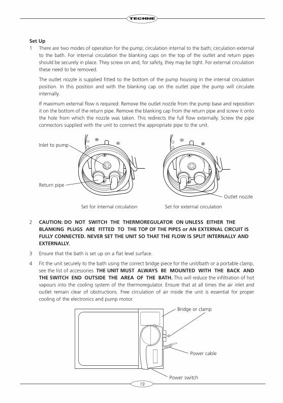
set Up1 There are two modes of operation for the pump; circulation internal to the bath; circulation external
to the bath. For internal circulation the blanking caps on the top of the outlet and return pipes should be securely in place. They screw on and, for safety, they may be tight. For external circulation these need to be removed.
The outlet nozzle is supplied fitted to the bottom of the pump housing in the internal circulation position. In this position and with the blanking cap on the outlet pipe the pump will circulate internally.
If maximum external flow is required: Remove the outlet nozzle from the pump base and reposition it on the bottom of the return pipe. Remove the blanking cap from the return pipe and screw it onto the hole from which the nozzle was taken. This redirects the full flow externally. Screw the pipe connectors supplied with the unit to connect the appropriate pipe to the unit.
Inlet to pump
Return pipe
Outlet nozzle
Set for internal circulation Set for external circulation
2 cAUTIOn: DO nOT sWITch ThE ThErMOrEgUlATOr On UnlEss EIThEr ThE blAnkIng plUgs ArE fITTED TO ThE TOp Of ThE pIpEs or An EXTErnAl cIrcUIT Is fUllY cOnnEcTED. nEvEr sET ThE UnIT sO ThAT ThE flOW Is splIT InTErnAllY AnD EXTErnAllY.
3 Ensure that the bath is set up on a flat level surface.
4 Fit the unit securely to the bath using the correct bridge piece for the unit/bath or a portable clamp, see the list of accessories. ThE UnIT MUsT AlWAYs bE MOUnTED WITh ThE bAck AnD ThE sWITch EnD OUTsIDE ThE ArEA Of ThE bATh. This will reduce the infiltration of hot vapours into the cooling system of the thermoregulator. Ensure that at all times the air inlet and outlet remain clear of obstructions. Free circulation of air inside the unit is essential for proper cooling of the electronics and pump motor.
19
Bridge or clamp
Power cable
Power switch
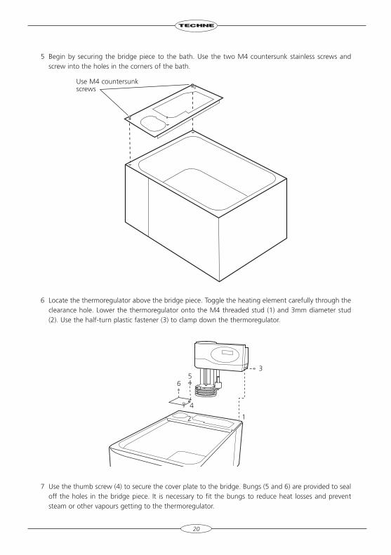
5 Begin by securing the bridge piece to the bath. Use the two M4 countersunk stainless screws and screw into the holes in the corners of the bath.
6 Locate the thermoregulator above the bridge piece. Toggle the heating element carefully through the clearance hole. Lower the thermoregulator onto the M4 threaded stud (1) and 3mm diameter stud (2). Use the half-turn plastic fastener (3) to clamp down the thermoregulator.
7 Use the thumb screw (4) to secure the cover plate to the bridge. Bungs (5 and 6) are provided to seal off the holes in the bridge piece. It is necessary to fit the bungs to reduce heat losses and prevent steam or other vapours getting to the thermoregulator.
20
Use M4 countersunkscrews
3
4
65
12
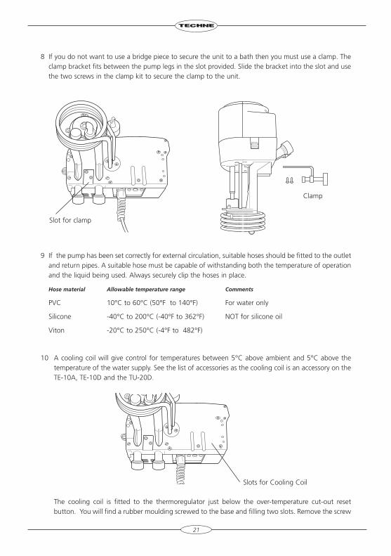
8 If you do not want to use a bridge piece to secure the unit to a bath then you must use a clamp. The clamp bracket fits between the pump legs in the slot provided. Slide the bracket into the slot and use the two screws in the clamp kit to secure the clamp to the unit.
9 If the pump has been set correctly for external circulation, suitable hoses should be fitted to the outlet and return pipes. A suitable hose must be capable of withstanding both the temperature of operation and the liquid being used. Always securely clip the hoses in place.
Hose material Allowable temperature range Comments
PVC 10°C to 60°C (50°F to 140°F) For water only
Silicone -40°C to 200°C (-40°F to 362°F) NOT for silicone oil
Viton -20°C to 250°C (-4°F to 482°F)
10 A cooling coil will give control for temperatures between 5°C above ambient and 5°C above the temperature of the water supply. See the list of accessories as the cooling coil is an accessory on the TE-10A, TE-10D and the TU-20D.
The cooling coil is fitted to the thermoregulator just below the over-temperature cut-out reset button. You will find a rubber moulding screwed to the base and filling two slots. Remove the screw
21
Slots for Cooling Coil
Slot for clamp
Clamp
and moulding and use the screw to fit the cooling coil in the slots. Keep the moulding in a safe place in case you need to replace it. Connect a hose from a tap to one end of the coil and from the other end of the coil to drain. Adjust the water flow to give the required cooling.
11 For lower temperatures, a Dip Cooler such as a Techne RU-200 or RU-500 or a Flow Cooler such as the FC-200 or FC-500 is required. Alternatively you could use either the RB-5A or the RB-12A Techne refrigerated baths, which have integrated fridge coils and no additional cooling mechanism is required.
See the individual instruction manuals for installation information.
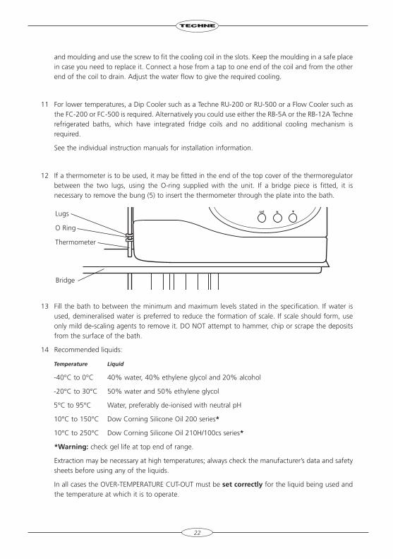
12 If a thermometer is to be used, it may be fitted in the end of the top cover of the thermoregulator between the two lugs, using the O-ring supplied with the unit. If a bridge piece is fitted, it is necessary to remove the bung (5) to insert the thermometer through the plate into the bath.
13 Fill the bath to between the minimum and maximum levels stated in the specification. If water is used, demineralised water is preferred to reduce the formation of scale. If scale should form, use only mild de-scaling agents to remove it. DO NOT attempt to hammer, chip or scrape the deposits from the surface of the bath.
14 Recommended liquids:
Temperature Liquid
-40°C to 0°C 40% water, 40% ethylene glycol and 20% alcohol
-20°C to 30°C 50% water and 50% ethylene glycol
5°C to 95°C Water, preferably de-ionised with neutral pH
10°C to 150°C Dow Corning Silicone Oil 200 series*
10°C to 250°C Dow Corning Silicone Oil 210H/100cs series*
*Warning: check gel life at top end of range.
Extraction may be necessary at high temperatures; always check the manufacturer’s data and safety sheets before using any of the liquids.
In all cases the OVER-TEMPERATURE CUT-OUT must be set correctly for the liquid being used and the temperature at which it is to operate.
22
Lugs
O Ring
Thermometer
Bridge
15 A bath that is fitted with a lid or insulating ball blanket gives the best operating conditions. A lid or ball blanket will prevent vapour loss, heat loss and give better temperature control. If an open bath is used above 80°C (ie where steam or other readily condensing vapours are present) the operation of the unit, particularly the digital display on the TE-10D and the TU-20D, may be affected.
Below about 80°C a cover becomes less important but will still give better temperature control.
16 The symbols next to the indicator lamps on the front panel of the thermoregulators have the following meanings:
: the power indicator
: the heater indicator
: the over-temperature indicator
17 Symbols on the switch have the following meanings:
I : mains switch On
O : mains switch Off
23
spEcIfIcATIOn
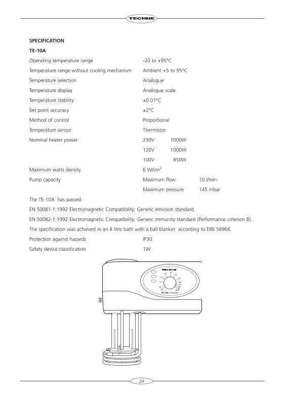
TE-10A
Operating temperature range -20 to +95°C
Temperature range without cooling mechanism Ambient +5 to 95°C
Temperature selection Analogue
Temperature display Analogue scale
Temperature stability ±0.01°C
Set point accuracy ±2°C
Method of control Proportional
Temperature sensor Thermistor
Nominal heater power 230V 1000W
120V 1000W
100V 850W
Maximum watts density 6 W/cm2
Pump capacity Maximum flow 10 l/min
Maximum pressure 145 mbar
The TE-10A has passed:
EN 50081-1:1992 Electromagnetic Compatibility; Generic emission standard.
EN 50082-1:1992 Electromagnetic Compatibility; Generic immunity standard (Performance criterion B).
The specification was achieved in an 8 litre bath with a ball blanket according to DIN 58966.
Protection against hazards IP30
Safety device classification 1W
24
spEcIfIcATIOn
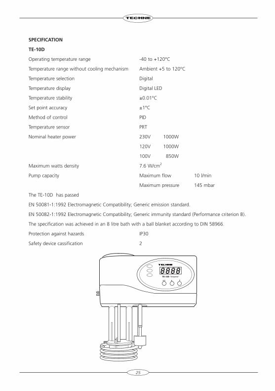
TE-10D
Operating temperature range -40 to +120°C
Temperature range without cooling mechanism Ambient +5 to 120°C
Temperature selection Digital
Temperature display Digital LED
Temperature stability ±0.01°C
Set point accuracy ±1°C
Method of control PID
Temperature sensor PRT
Nominal heater power 230V 1000W
120V 1000W
100V 850W
Maximum watts density 7.6 W/cm2
Pump capacity Maximum flow 10 l/min
Maximum pressure 145 mbar
The TE-10D has passed
EN 50081-1:1992 Electromagnetic Compatibility; Generic emission standard.
EN 50082-1:1992 Electromagnetic Compatibility; Generic immunity standard (Performance criterion B).
The specification was achieved in an 8 litre bath with a ball blanket according to DIN 58966.
Protection against hazards IP30
Safety device cassification 2
25
26
spEcIfIcATIOn
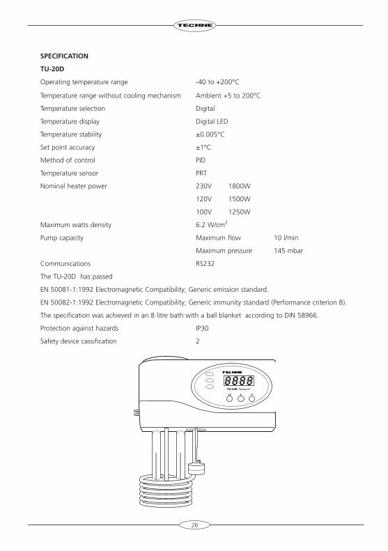
TU-20D
Operating temperature range -40 to +200°C
Temperature range without cooling mechanism Ambient +5 to 200°C
Temperature selection Digital
Temperature display Digital LED
Temperature stability ±0.005°C
Set point accuracy ±1°C
Method of control PID
Temperature sensor PRT
Nominal heater power 230V 1800W
120V 1500W
100V 1250W
Maximum watts density 6.2 W/cm2
Pump capacity Maximum flow 10 l/min
Maximum pressure 145 mbar
Communications RS232
The TU-20D has passed
EN 50081-1:1992 Electromagnetic Compatibility; Generic emission standard.
EN 50082-1:1992 Electromagnetic Compatibility; Generic immunity standard (Performance criterion B).
The specification was achieved in an 8 litre bath with a ball blanket according to DIN 58966.
Protection against hazards IP30
Safety device cassification 2
27
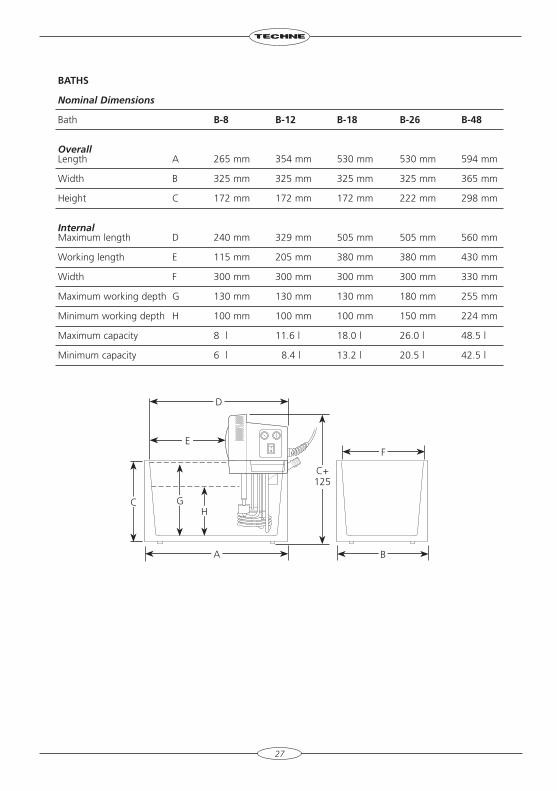
bAThs
Nominal Dimensions
Bath b-8 b-12 b-18 b-26 b-48
OverallLength A 265 mm 354 mm 530 mm 530 mm 594 mm
Width B 325 mm 325 mm 325 mm 325 mm 365 mm
Height C 172 mm 172 mm 172 mm 222 mm 298 mm
InternalMaximum length D 240 mm 329 mm 505 mm 505 mm 560 mm
Working length E 115 mm 205 mm 380 mm 380 mm 430 mm
Width F 300 mm 300 mm 300 mm 300 mm 330 mm
Maximum working depth G 130 mm 130 mm 130 mm 180 mm 255 mm
Minimum working depth H 100 mm 100 mm 100 mm 150 mm 224 mm
Maximum capacity 8 l 11.6 l 18.0 l 26.0 l 48.5 l
Minimum capacity 6 l 8.4 l 13.2 l 20.5 l 42.5 l
F
BA
C GH
E
D
C+ 125
OpErATIOn
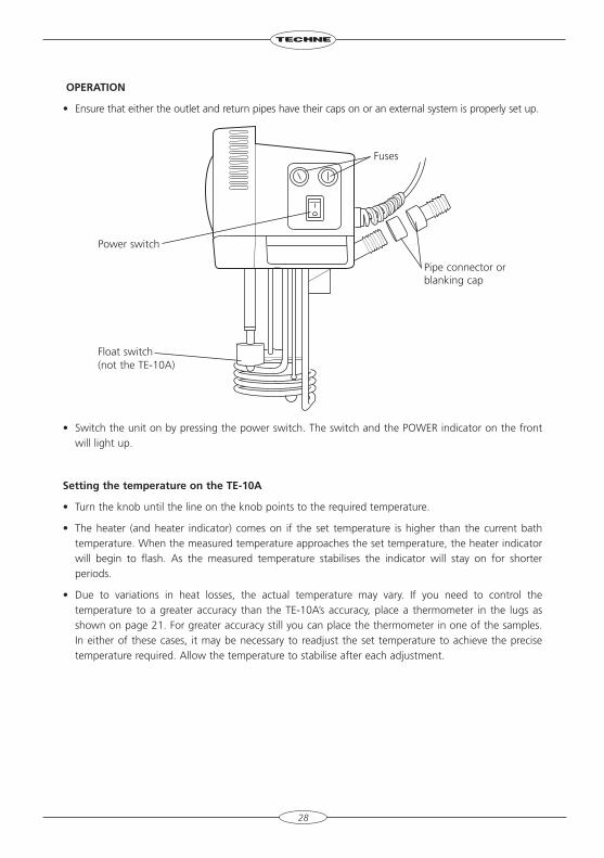
• Ensure that either the outlet and return pipes have their caps on or an external system is properly set up.
• Switch the unit on by pressing the power switch. The switch and the POWER indicator on the front will light up.
setting the temperature on the TE-10A
• Turn the knob until the line on the knob points to the required temperature.
• The heater (and heater indicator) comes on if the set temperature is higher than the current bath temperature. When the measured temperature approaches the set temperature, the heater indicator will begin to flash. As the measured temperature stabilises the indicator will stay on for shorter periods.
• Due to variations in heat losses, the actual temperature may vary. If you need to control the temperature to a greater accuracy than the TE-10A’s accuracy, place a thermometer in the lugs as shown on page 21. For greater accuracy still you can place the thermometer in one of the samples. In either of these cases, it may be necessary to readjust the set temperature to achieve the precise temperature required. Allow the temperature to stabilise after each adjustment.
28
Fuses
Pipe connector or blanking cap
Power switch
Float switch(not the TE-10A)
29
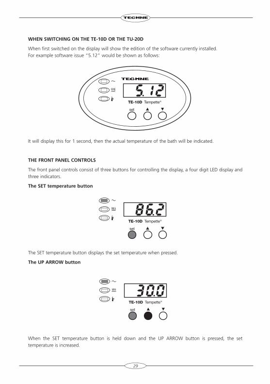
WhEn sWITchIng On ThE TE-10D Or ThE TU-20D
When first switched on the display will show the edition of the software currently installed. For example software issue “5.12” would be shown as follows:
It will display this for 1 second, then the actual temperature of the bath will be indicated.
ThE frOnT pAnEl cOnTrOls
The front panel controls consist of three buttons for controlling the display, a four digit LED display and three indicators.
The sET temperature button
The SET temperature button displays the set temperature when pressed.
The Up ArrOW button
When the SET temperature button is held down and the UP ARROW button is pressed, the set temperature is increased.
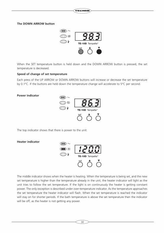
The DOWn ArrOW button
When the SET temperature button is held down and the DOWN ARROW button is pressed, the set temperature is decreased.
speed of change of set temperature
Each press of the UP ARROW or DOWN ARROW buttons will increase or decrease the set temperature by 0.1°C. If the buttons are held down the temperature change will accelerate to 5°C per second.
power indicator
The top indicator shows that there is power to the unit.
heater indicator
The middle indicator shows when the heater is heating. When the temperature is being set, and the new set temperature is higher than the temperature already in the unit, the heater indicator will light as the unit tries to follow the set temperature. If the light is on continuously the heater is getting constant power. The only exception is described under over-temperature indicator. As the temperature approaches the set temperature the heater indicator will flash. When the set temperature is reached the indicator will stay on for shorter periods. If the bath temperature is above the set temperature then the indicator will be off, as the heater is not getting any power.
30
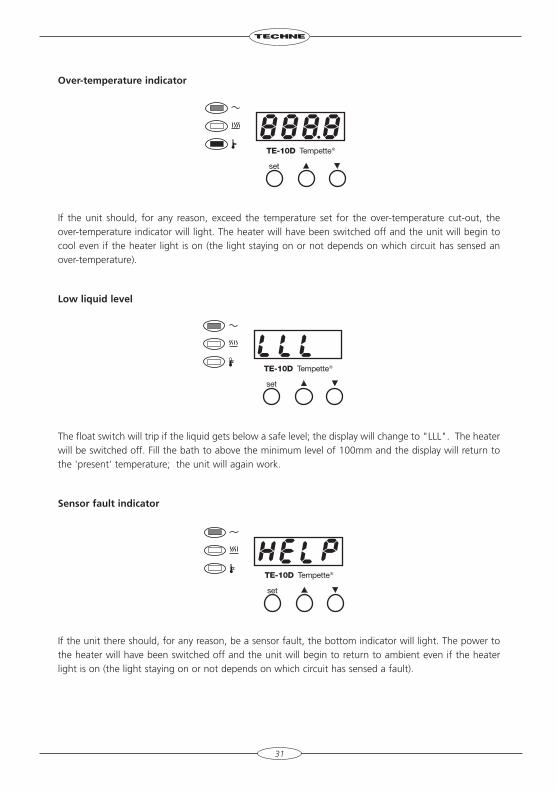
Over-temperature indicator
If the unit should, for any reason, exceed the temperature set for the over-temperature cut-out, the over-temperature indicator will light. The heater will have been switched off and the unit will begin to cool even if the heater light is on (the light staying on or not depends on which circuit has sensed an over-temperature).
low liquid level
The float switch will trip if the liquid gets below a safe level; the display will change to "LLL". The heater will be switched off. Fill the bath to above the minimum level of 100mm and the display will return to the 'present' temperature; the unit will again work.
sensor fault indicator
If the unit there should, for any reason, be a sensor fault, the bottom indicator will light. The power to the heater will have been switched off and the unit will begin to return to ambient even if the heater light is on (the light staying on or not depends on which circuit has sensed a fault).
31
AfTEr UsE
When you have finished heating samples, remember that parts of the unit and the samples may be very hot. Take the precautions listed earlier. We recommend that the samples should be allowed to cool to 50°C before being removed from the bath. They will still have to be handled with care.
Should you want to remove the unit from the bath, it too should be allowed to cool to 50°C before being removed.
Remember the bridge, the lid (if used), the bath and all other parts close to the bath will be hot while it is in use.
32
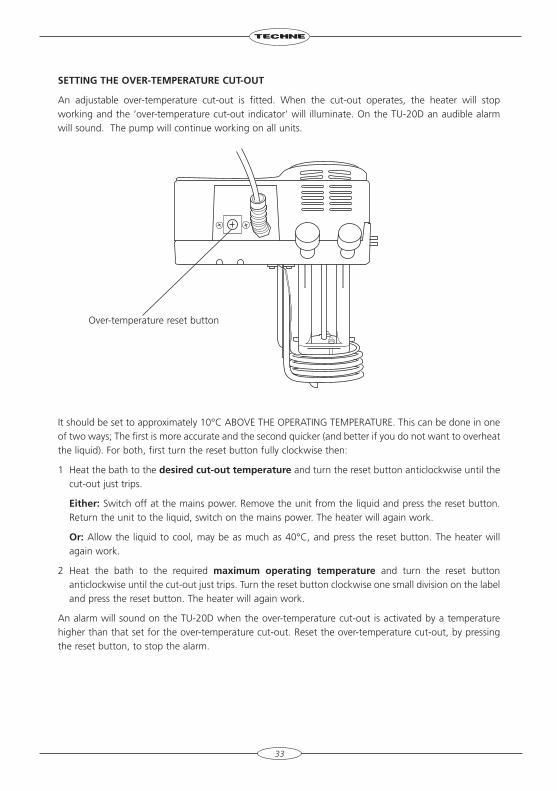
sETTIng ThE OvEr-TEMpErATUrE cUT-OUT
An adjustable over-temperature cut-out is fitted. When the cut-out operates, the heater will stop working and the ‘over-temperature cut-out indicator’ will illuminate. On the TU-20D an audible alarm will sound. The pump will continue working on all units.
It should be set to approximately 10°C ABOVE THE OPERATING TEMPERATURE. This can be done in one of two ways; The first is more accurate and the second quicker (and better if you do not want to overheat the liquid). For both, first turn the reset button fully clockwise then:
1 Heat the bath to the desired cut-out temperature and turn the reset button anticlockwise until the cut-out just trips.
Either: Switch off at the mains power. Remove the unit from the liquid and press the reset button. Return the unit to the liquid, switch on the mains power. The heater will again work.
Or: Allow the liquid to cool, may be as much as 40°C, and press the reset button. The heater will again work.
2 Heat the bath to the required maximum operating temperature and turn the reset button anticlockwise until the cut-out just trips. Turn the reset button clockwise one small division on the label and press the reset button. The heater will again work.
An alarm will sound on the TU-20D when the over-temperature cut-out is activated by a temperature higher than that set for the over-temperature cut-out. Reset the over-temperature cut-out, by pressing the reset button, to stop the alarm.
33
Over-temperature reset button
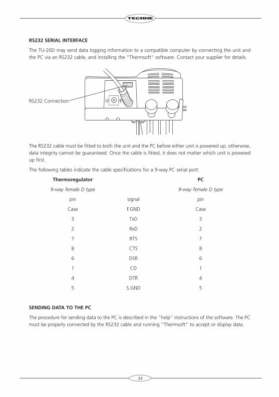
rs232 sErIAl InTErfAcE
The TU-20D may send data logging information to a compatible computer by connecting the unit and the PC via an RS232 cable, and installing the “Thermsoft” software. Contact your supplier for details.
The RS232 cable must be fitted to both the unit and the PC before either unit is powered up, otherwise, data integrity cannot be guaranteed. Once the cable is fitted, it does not matter which unit is powered up first.
The following tables indicate the cable specifications for a 9-way PC serial port:
Thermoregulator pc
9-way female D type 9-way female D type
pin signal pin
Case F.GND Case
3 TxD 3
2 RxD 2
7 RTS 7
8 CTS 8
6 DSR 6
1 CD 1
4 DTR 4
5 S.GND 5
sEnDIng DATA TO ThE pc
The procedure for sending data to the PC is described in the “help” instructions of the software. The PC must be properly connected by the RS232 cable and running “Thermsoft” to accept or display data.
34
RS232 Connection
ADDITIOnAl InfOrMATIOn
NOTE THAT THIS EQUIPMENT SHOULD ONLY BE DISMANTLED BY PROPERLY TRAINED PERSONNEL. rEMOvIng ThE TOp cAsE EXpOsEs pOTEnTIAllY lEThAl MAIns vOlTAgE. THERE ARE NO OPERATOR MAINTAINABLE PARTS WITHIN THE EQUIPMENT.
In the unlikely event that you experience any problems with your Thermoregulator which cannot easily be remedied, you should contact your supplier and return the unit if necessary. Please include any details of the fault observed and remember to return the unit in its original packing. Techne accept no responsibility for damage to units which are not properly packed for shipping: if in doubt, contact your supplier.
OpErATOr MAInTEnAncE
1. cleaning
Before cleaning your unit ALWAYS disconnect from the power supply and allow to cool below 50°C.
Your Thermoregulator can be cleaned by wiping with a damp soapy cloth. Care should be exercised to prevent water from running inside the unit. Do not use abrasive cleaners.
2. Over-temperature cut-out
The over-temperature cut-out is a sensitive mechanical device and mechanical shock can cause it to trip.
• In the event of no heater power, check the mains plug and lead, then reset the cut-out control.
• Repeated operation of the cut-out indicates a serious fault: you may need to return the unit to your supplier for repair.
3. fuses
Your unit is protected by two fuses.
TE-10A & TE-10D 230V 2 x F5A; 120/100V 2 x F10A
TU-20D 230V 2 x F10A; 120/100V 2 x T16A
These should only be changed by suitably qualified personnel.
The fuses must only be replaced by a fuse of the same type and value.
If the fuses blow persistently, a serious fault is indicated and you may need to return the unit to your supplier for repair.
35
cAlIbrATIOn Of ThE TE-10D AnD TU-20D
remember that if you change the calibration from that set at the factory you may change the calibration at all temperatures. You may get different calibration with different baths and/or liquids.
In order to ensure that the calibration you are setting is correct, you will need to use an independent calibrated probe or thermometer.
Set the temperature display to the particular temperature at which you require to control. Measure the actual temperature of the bath liquid using a calibrated probe or thermometer.
If the calibration is not correct then you can follow this procedure.
a Hold down the Up and Down buttons and then press the Set button at the same time for 5 seconds.
b The display will change from the bath temperature to “EEEE”.
c Press the ‘SET’ button and either the ‘UP’ or the ‘DOWN’ button to adjust the display to the same temperature as the measured value.
d Press ’UP’ and ‘DOWN together to confirm the value. The display will return to the bath temperature and the unit will control with the new calibration parameters.
36
replacement parts
Each unit is supplied with an O ring for a thermometer. The following parts may be purchased if replacements or alternatives are required:
Part number Description
6007349 O ring (thermometer)
6103913 Cap seal
6103475 Cap
6103804 Pipe connection seal
6103771 Pipe connection nozzle
6103460 Bottom outlet nozzle
37
AccEssOrIEs
There are many accessories both for the thermoregulators and the baths. These are constantly being updated and details can be found in Techne Sales literature. However they include:
Flat Lids To fit Bath Gabled Lids To fit Bath
FFLAT08 B-8 FGABLE08 B-8
FFLAT12 B-12 FGABLE12 B-12
FFLAT18 B-18 or B-26 FGABLE18 B-18 or B-26
FFLAT48 B-48 FGABLE48 B-48
Clamp
FCLAMP TE clamp
FCLAMP2 TU clamp
Cooling Coil
FCC01 Cooling Coil
Fridge Baths Dip Coolers
FRB5D RB-5A 230V UK FRU2D RU-200 230V UK
FRB5E RB-5A 230V Europe FRU2E RU-200 230V Europe
FRB5P RB-5A 120V FRU2P RU-200 120V
FRB2D RB-12A 230V UK FRU5D RU-500 230V UK
FRB2E RB-12A 230V Europe FRU5E RU-500 230V Europe
FRB2P RB-12A 120V FRU5P RU-500 120V
Flow Coolers
FFC2D FC-200 230V UK
FFC2D FC-200 230V Europe
FFC2P FC-200 120V
FFC5D FC-500 230V UK
FFC5D FC-500 230V Europe
FFC5P FC-500 120V
FTU232 “Thermsoft” kit inc: disc, cable and connector for TU-20D
38
nOTEs
39

bibby scientific ltdBeacon Road Stone Staffordshire ST15 0SAUnited KingdomTel: +44 (0)1785 812121 Fax: +44 (0)1785 810405 e-mail: [email protected]
bibby scientific france sAsZI du Rocher Vert - BP 7977793 Nemours Cedex FranceTel: +33 1 64 45 13 13 Fax: +33 1 64 45 13 00 e-mail: [email protected]
bibby scientific Italia srlVia Alcide de Gasperi 5620077 Riozzo di Cerro al LambroMilano ItaliaTel: +39 (0)2 98230679Fax: +39 (0)2 98230211 e-mail: [email protected]
bibby scientific Us ltd 3 Terri Lane Suite 10 Burlington NJ 08016 USATel: 800-225-9243 Fax: 609-589-2571www.bibby-scientific.com
bibby scientific ltd - singaporePrudential Tower Level 2630 Cecil StreetSingapore 049712Tel: +65 6631 2976Fax: +44 (0)1785 810405e-mail: [email protected]
bibby scientific - Middle EastPO Box 27842Engomi 2433,Nicosia, CyprusTel: +357 22 660 423Fax: +357 22 660 424Email: [email protected]: www.bibby-scientific.com